
Severe Plastic Deformation by Machining …web.ics.purdue.edu/~chandy/MetTransB_msevier.pdf · by...
12
Severe Plastic Deformation by Machining Characterized by Finite Element Simulation M. SEVIER, H.T.Y. YANG, S. LEE, and S. CHANDRASEKAR A finite element model of large strain deformation in machining is presented in the context of using machining as a controlled method for severe plastic deformation (SPD). Various char- acteristics of the large strain deformation field associated with chip formation, including strain, strain distribution, strain rate, and velocity field, are calculated using the model and compared with direct measurements in plane strain machining. Reasonable agreement is found for all cases considered. The versatility and accuracy of the finite element model are demonstrated, especially in the range of highly negative rake angles, wherein the shear plane model of machining is less applicable due to the nature of material flow around the tool cutting edge. The influence of the tool rake angle and friction at the tool-chip interface on the deformation is explored and used to establish correspondences between controllable machining input parameters and deformation parameters. These correspondences indicate that machining is a viable, controlled method of severe plastic deformation. Implications of the results for creation of nanostructured and ultra- fine-grained alloys by machining are briefly highlighted. DOI: 10.1007/s11663-007-9103-9 Ó The Minerals, Metals & Materials Society and ASM International 2007 I. INTRODUCTION A commonly used approach for refinement of micro- structure in metals and alloys is severe plastic deforma- tion (SPD). [1–3] Severe plastic deformation generally refers to a class of processes wherein a material is deformed to large plastic strains (>3) through the use of multiple passes of deformation. The role of severe plastic deformation in microstructure refinement is best highlighted in the pioneering studies of Embury and Fisher [4] on deformation of pearlite, and Langford and Cohen [5] on iron. Langford and Cohen, [5] for example, imposed large plastic strains in iron by repeated passes of wire drawing and found the microstructure of the deformed iron wire to be composed of grains and dislocation substructures with sizes in the sub-microm- eter range. Furthermore, there was a significant increase in the flow stress of the wire. More recently severe plastic deformation has become the preferred route for pro- ducing bulk nanostructured materials. [1,3,6] Two conventional severe plastic deformation proce- dures are equal channel angular pressing (ECAP) [1,3,6] and high pressure torsion (HPT). [1] In equal channel angular, a pressing sample is extruded repeatedly through a rigid die with a bend that imposes shear on the material. The cross sections of the die at the inlet and exit are kept the same so that the sample does not undergo any shape change. The sample material typi- cally experiences a shear strain of 1 to 2 per pass and multiple passes of deformation are used to impose large strains and achieve refinement of the microstructure. In high pressure torsional straining, a thin circular disk is subjected to shear under superimposed normal pressure applied between a die and a rotating shaft. The shear is transmitted to the disk sample by friction as the shaft is rotated with respect to the die, thereby imposing large strains in the material. The resulting strain distribution is quite inhomogeneous through the thickness and along the radius of the sample. While conventional severe plastic deformation studies have provided insights into mechanisms of microstruc- ture refinement in metals and alloys of low initial strength, they do possess some limitations. First, multi- ple stages of deformation are needed to create the large plastic strains. Second, moderate and high-strength metals and alloys are difficult to deform at near-ambient temperatures in this manner due to constraints imposed by the forming equipment, including durability of tools and dies. Last, there are uncertainties pertaining to knowledge and control of deformation field parameters. A potentially attractive route for imposing large plastic strains and strain rates in a single pass of deformation, while overcoming the aforementioned limitations, is the process of chip formation by machin- ing. In contrast to rolling, extrusion, equal channel angular pressing and high pressure torsional straining, machining can impose uniform strains that are suffi- ciently large to realize ultra-fine-grained microstructures in the chip in only one pass. [7–9] Furthermore, machining can be used for severe plastic deformation of metals and alloys of high initial strength at various strain rates ranging from low to high. [8,10] The development of machining as a controlled method of severe plastic M. SEVIER, Graduate Student, and H.T.Y. YANG, Professor, are with the Department of Mechanical Engineering, University of California, Santa Barbara, CA 93106, USA. Contact e-mail: [email protected] S. LEE, Graduate Student, and S. CHANDRASEKAR, Professor, are with the Center for Materials Processing and Tribology, School of Industrial Engineering, Purdue University, West Lafayette, IN 47907-2023, USA. Manuscript submitted March 8, 2007. Article published online November 29, 2007. METALLURGICAL AND MATERIALS TRANSACTIONS B VOLUME 38B, DECEMBER 2007—927
Transcript of Severe Plastic Deformation by Machining …web.ics.purdue.edu/~chandy/MetTransB_msevier.pdf · by...

Severe Plastic Deformation by Machining Characterizedby Finite Element Simulation
M. SEVIER, H.T.Y. YANG, S. LEE, and S. CHANDRASEKAR
A finite element model of large strain deformation in machining is presented in the context ofusing machining as a controlled method for severe plastic deformation (SPD). Various char-acteristics of the large strain deformation field associated with chip formation, including strain,strain distribution, strain rate, and velocity field, are calculated using the model and comparedwith direct measurements in plane strain machining. Reasonable agreement is found for all casesconsidered. The versatility and accuracy of the finite element model are demonstrated, especiallyin the range of highly negative rake angles, wherein the shear plane model of machining is lessapplicable due to the nature of material flow around the tool cutting edge. The influence of thetool rake angle and friction at the tool-chip interface on the deformation is explored and used toestablish correspondences between controllable machining input parameters and deformationparameters. These correspondences indicate that machining is a viable, controlled method ofsevere plastic deformation. Implications of the results for creation of nanostructured and ultra-fine-grained alloys by machining are briefly highlighted.
DOI: 10.1007/s11663-007-9103-9� The Minerals, Metals & Materials Society and ASM International 2007
I. INTRODUCTION
A commonly used approach for refinement of micro-structure in metals and alloys is severe plastic deforma-tion (SPD).[1–3] Severe plastic deformation generallyrefers to a class of processes wherein a material isdeformed to large plastic strains (>3) through the use ofmultiple passes of deformation. The role of severeplastic deformation in microstructure refinement is besthighlighted in the pioneering studies of Embury andFisher[4] on deformation of pearlite, and Langford andCohen[5] on iron. Langford and Cohen,[5] for example,imposed large plastic strains in iron by repeated passesof wire drawing and found the microstructure of thedeformed iron wire to be composed of grains anddislocation substructures with sizes in the sub-microm-eter range. Furthermore, there was a significant increasein the flow stress of the wire. More recently severe plasticdeformation has become the preferred route for pro-ducing bulk nanostructured materials.[1,3,6]
Two conventional severe plastic deformation proce-dures are equal channel angular pressing (ECAP)[1,3,6]
and high pressure torsion (HPT).[1] In equal channelangular, a pressing sample is extruded repeatedlythrough a rigid die with a bend that imposes shear onthe material. The cross sections of the die at the inlet andexit are kept the same so that the sample does not
undergo any shape change. The sample material typi-cally experiences a shear strain of 1 to 2 per pass andmultiple passes of deformation are used to impose largestrains and achieve refinement of the microstructure. Inhigh pressure torsional straining, a thin circular disk issubjected to shear under superimposed normal pressureapplied between a die and a rotating shaft. The shear istransmitted to the disk sample by friction as the shaft isrotated with respect to the die, thereby imposing largestrains in the material. The resulting strain distributionis quite inhomogeneous through the thickness and alongthe radius of the sample.While conventional severe plastic deformation studies
have provided insights into mechanisms of microstruc-ture refinement in metals and alloys of low initialstrength, they do possess some limitations. First, multi-ple stages of deformation are needed to create the largeplastic strains. Second, moderate and high-strengthmetals and alloys are difficult to deform at near-ambienttemperatures in this manner due to constraints imposedby the forming equipment, including durability of toolsand dies. Last, there are uncertainties pertaining toknowledge and control of deformation field parameters.A potentially attractive route for imposing large
plastic strains and strain rates in a single pass ofdeformation, while overcoming the aforementionedlimitations, is the process of chip formation by machin-ing. In contrast to rolling, extrusion, equal channelangular pressing and high pressure torsional straining,machining can impose uniform strains that are suffi-ciently large to realize ultra-fine-grained microstructuresin the chip in only one pass.[7–9] Furthermore, machiningcan be used for severe plastic deformation of metals andalloys of high initial strength at various strain ratesranging from low to high.[8,10] The development ofmachining as a controlled method of severe plastic
M. SEVIER, Graduate Student, and H.T.Y. YANG, Professor, arewith the Department of Mechanical Engineering, University ofCalifornia, Santa Barbara, CA 93106, USA. Contact e-mail:[email protected] S. LEE, Graduate Student, andS. CHANDRASEKAR, Professor, are with the Center for MaterialsProcessing and Tribology, School of Industrial Engineering, PurdueUniversity, West Lafayette, IN 47907-2023, USA.
Manuscript submitted March 8, 2007.Article published online November 29, 2007.
METALLURGICAL AND MATERIALS TRANSACTIONS B VOLUME 38B, DECEMBER 2007—927
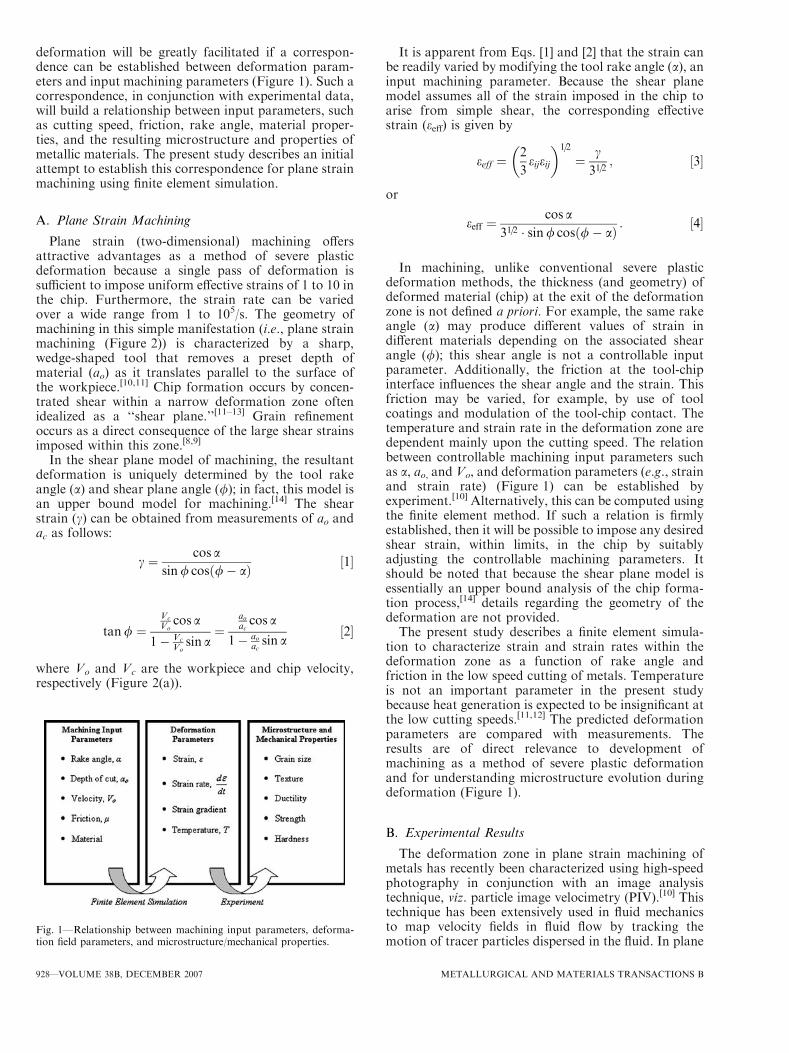
deformation will be greatly facilitated if a correspon-dence can be established between deformation param-eters and input machining parameters (Figure 1). Such acorrespondence, in conjunction with experimental data,will build a relationship between input parameters, suchas cutting speed, friction, rake angle, material proper-ties, and the resulting microstructure and properties ofmetallic materials. The present study describes an initialattempt to establish this correspondence for plane strainmachining using finite element simulation.
A. Plane Strain Machining
Plane strain (two-dimensional) machining offersattractive advantages as a method of severe plasticdeformation because a single pass of deformation issufficient to impose uniform effective strains of 1 to 10 inthe chip. Furthermore, the strain rate can be variedover a wide range from 1 to 105/s. The geometry ofmachining in this simple manifestation (i.e., plane strainmachining (Figure 2)) is characterized by a sharp,wedge-shaped tool that removes a preset depth ofmaterial (ao) as it translates parallel to the surface ofthe workpiece.[10,11] Chip formation occurs by concen-trated shear within a narrow deformation zone oftenidealized as a ‘‘shear plane.’’[11–13] Grain refinementoccurs as a direct consequence of the large shear strainsimposed within this zone.[8,9]
In the shear plane model of machining, the resultantdeformation is uniquely determined by the tool rakeangle (a) and shear plane angle (/); in fact, this model isan upper bound model for machining.[14] The shearstrain (c) can be obtained from measurements of ao andac as follows:
c ¼ cos asin/ cosð/� aÞ ½1�
tan/ ¼Vc
Vocos a
1� Vc
Vosin a
¼aoaccos a
1� aoacsin a
½2�
where Vo and Vc are the workpiece and chip velocity,respectively (Figure 2(a)).
It is apparent from Eqs. [1] and [2] that the strain canbe readily varied by modifying the tool rake angle (a), aninput machining parameter. Because the shear planemodel assumes all of the strain imposed in the chip toarise from simple shear, the corresponding effectivestrain (eeff) is given by
eeff ¼2
3eijeij
� �1=2
¼ c
31=2; ½3�
or
eeff ¼cos a
31=2 � sin/ cosð/� aÞ : ½4�
In machining, unlike conventional severe plasticdeformation methods, the thickness (and geometry) ofdeformed material (chip) at the exit of the deformationzone is not defined a priori. For example, the same rakeangle (a) may produce different values of strain indifferent materials depending on the associated shearangle (/); this shear angle is not a controllable inputparameter. Additionally, the friction at the tool-chipinterface influences the shear angle and the strain. Thisfriction may be varied, for example, by use of toolcoatings and modulation of the tool-chip contact. Thetemperature and strain rate in the deformation zone aredependent mainly upon the cutting speed. The relationbetween controllable machining input parameters suchas a, ao, and Vo, and deformation parameters (e.g., strainand strain rate) (Figure 1) can be established byexperiment.[10] Alternatively, this can be computed usingthe finite element method. If such a relation is firmlyestablished, then it will be possible to impose any desiredshear strain, within limits, in the chip by suitablyadjusting the controllable machining parameters. Itshould be noted that because the shear plane model isessentially an upper bound analysis of the chip forma-tion process,[14] details regarding the geometry of thedeformation are not provided.The present study describes a finite element simula-
tion to characterize strain and strain rates within thedeformation zone as a function of rake angle andfriction in the low speed cutting of metals. Temperatureis not an important parameter in the present studybecause heat generation is expected to be insignificant atthe low cutting speeds.[11,12] The predicted deformationparameters are compared with measurements. Theresults are of direct relevance to development ofmachining as a method of severe plastic deformationand for understanding microstructure evolution duringdeformation (Figure 1).
B. Experimental Results
The deformation zone in plane strain machining ofmetals has recently been characterized using high-speedphotography in conjunction with an image analysistechnique, viz. particle image velocimetry (PIV).[10] Thistechnique has been extensively used in fluid mechanicsto map velocity fields in fluid flow by tracking themotion of tracer particles dispersed in the fluid. In plane
Fig. 1—Relationship between machining input parameters, deforma-tion field parameters, and microstructure/mechanical properties.
928—VOLUME 38B, DECEMBER 2007 METALLURGICAL AND MATERIALS TRANSACTIONS B

strain machining, the function of tracer particles isserved by asperity-like features created on a side of theworkpiece by abrasion or sand blasting (Figure 2(b)),which scatter light significantly different than thesurrounding regions in the metal. By measuring thedisplacement of these features over time using high-speed photography, velocity, strain rate, and strain datain the deformation zone, chip and workpiece subsurfacecan be obtained.[8,10] Experimental details pertaining tothe application of PIV to machining can be found inReferences 8 and 10. Figure 2(c) is an example of strainrate distribution in the deformation zone obtainedusing the PIV analysis in low-speed machining of lead.Because strain rate is a measure of the incremental strainimposed over a finite time-step associated with incre-mental advancement of the tool, the distribution ofstrain rate in Figure 2(c) provides a direct characteriza-tion of the size and extent of the deformation zone. It isseen from this figure that the deformation zone isnonplanar and has finite width. Similar conclusions havebeen arrived at in prior studies using quick-stop and
related observations.[12,13] Furthermore, the PIV analy-sis has shown that the cumulative strain imposed in thechip varies for different materials at the same tool rakeangle. These observations highlight the need for mod-eling of the chip formation process to relate machiningparameters (e.g., rake angle, velocity, and friction) todeformation parameters (e.g., strain, strain rate, andtemperature) (Figure 1).An important consequence of large strains imposed in
the chip is formation of a range of ultra-fine-grain andnanoscale microstructures. This is seen in Figure 3 forpure oxygen free high conductivity (OFHC) coppersubjected to different levels of plastic strain by varyingthe tool rake angle.[9] The nature of the microstructure isseen to be strongly dependent on the strain. In partic-ular, a switchover from elongated subgrain to nanoscaleequiaxed grain structures, with a significant fraction ofhigh-angle grain boundaries, is observed at the higherlevels of strain (Figure 3). This transition, which typi-cally occurs at a critical value of strain, is controllable invarious alloys by varying the deformation conditions.
Fig. 2—(a) Schematic of plane strain machining, (b) asperities on workpiece surface used in PIV analysis, and (c) example of strain rate distribu-tion in plane strain machining obtained by PIV.
METALLURGICAL AND MATERIALS TRANSACTIONS B VOLUME 38B, DECEMBER 2007—929

Again, effective modeling would enable control of chipmicrostructures by predicting the machining parametersrequired to produce predetermined ultra-fine-grainedmorphologies. Such modeling is possible through theuse of the finite element method.
II. FINITE ELEMENT MODELS FORMACHINING
A. Previous Models
The finite element method has been widely used tostudy machining processes. Klamecki�s model[15] waslimited to the incipient cutting stage. Shirakashi andUsui[16] assumed a steady-state chip geometry andadvanced the tool incrementally. Strenkowski andCarroll[17] were the first to model actual chip formationby having the nodes separate along a predefined‘‘parting line.’’ Other researchers have followed in their
path with the nodes ‘‘unhooked’’ according to variouslimiting criteria imposed somewhat arbitrarily (strain,distance from the tool tip, etc.).[18–22] However, insimulating chip formation as tensile rupture rather thanplastic flow as indicated by experiment,[23,24] thesemodels may be somewhat inaccurate in their predictionof deformation parameters. Furthermore, these earlystudies encountered difficulty in simulating cutting withlarge negative rake angles.[25]
In order to effectively model extreme plastic defor-mation involved in chip formation while maintainingmesh continuity, subsequent studies have used adaptivemeshing. Carroll and Strenkowski[26] adapted an Eule-rian reference frame wherein the mesh is held constantwhile a viscoplastic material flows through the givencontrol volume. Through iterative modification theeventual chip geometry could be determined as well asthe forces. Sekhon and Chenot[27] used a similar flowformulation with the addition of automatic remeshing toreflect changes in chip geometry.
Fig. 3—Transmission electron micrographs of chips cut from pure (OFHC) copper with different values of effective strain (eeff).
930—VOLUME 38B, DECEMBER 2007 METALLURGICAL AND MATERIALS TRANSACTIONS B
In 1995, the International Academy of ProductionEngineering (CIRP) established a working group ‘‘Mod-elling of Machining Operations’’ with the goal ofadvancing machining modeling techniques so that theywould be capable for use in industry. Current state ofthe art of modeling in machining has been well-addressed in keynote publications by members of thisgroup.[28,29] One such direction developed by Cerettiet al.[30] applies element deletion to the process of chipformation. In this type of simulation, elements havingreached a critical value of accumulated damage aresubsequently removed from the analysis. Recently, thistechnique has been successfully applied to simulate theformation of serrated or segmented chips, such as whenmachining a heterogeneous material[31] or when using anegative rake angle.[32]
Another direction for finite element development,more pertinent to the model presented in this study,involves Lagrangian mesh formulation with iterativeremeshing.[33,34] To address computational time con-cerns due to the periodic remeshing, researchers haveapplied an arbitrary Lagrangian Eulerian (ALE) for-mulation to the machining process.[35–37] In this type of
analysis, the nodal points of the finite element mesh mayhave degrees of freedom constrained by either materiallocation (Lagrangian), spatial location (Eulerian), or anarbitrary motion defined by the analyst. This methodallows for plastic flow to occur about the cutting tool tipwhile consistently maintaining a satisfactory aspect ratiofor the elements, making this technique particularlyconvenient for simulating a wide range of tool rakeangles.[38] Because machining has long been considered aprocess for making components, prior analyses havefocused mainly on characterizing parameters of theworkpiece surface and machining forces and paid muchless attention to predicting deformation characteristicsof the chip, the focus of this study.
B. Current Finite Element Approach
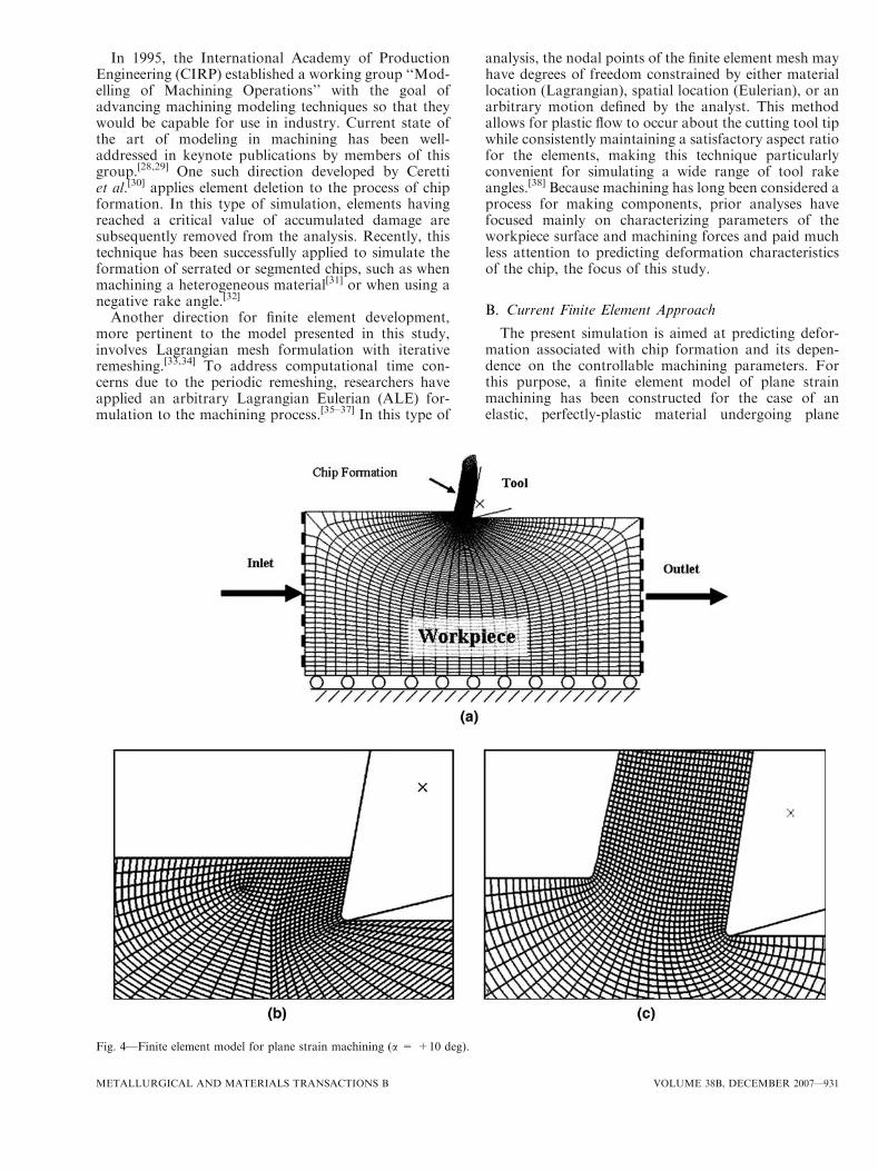
The present simulation is aimed at predicting defor-mation associated with chip formation and its depen-dence on the controllable machining parameters. Forthis purpose, a finite element model of plane strainmachining has been constructed for the case of anelastic, perfectly-plastic material undergoing plane
Fig. 4—Finite element model for plane strain machining (a = +10 deg).
METALLURGICAL AND MATERIALS TRANSACTIONS B VOLUME 38B, DECEMBER 2007—931

strain deformation at low speeds. A constant coefficientof friction (l) is prescribed at the chip-tool interface.Lead is used as the model material system because ofavailability of material properties and experimentalresults pertaining to deformation in machining.ABAQUS/CAE* is used for arrangement of model
elements and nodes (Figure 4). The basic element usedin the simulation is the isoparametric plane strain, 4node, 8 degree of freedom quadrilateral with reducedintegration.[39,40] The relative simplicity of this elementexpedites the computation run time of the simulationwith minimal loss of accuracy, for the class of examplesstudied here.
In order to accommodate the extreme plastic defor-mation encountered, ABAQUS/Explicit** is used to
solve the proposed nonlinear dynamic analysis. Thissolver is based on a central explicit integration ruleimplemented together with diagonal or ‘‘lumped’’ massmatrices.[41,42] Although this method employs a greatnumber of small increments, the simplicity of the matrixcomputation offers reduced simulation run time com-pared to standard finite element solvers.
Further promotion of finite element efficiency inexplicit formulation is achieved through ‘‘mass scaling.’’This procedure allows the minimum stable time incre-ment to be artificially increased through augmentationof the mass density of the material.[40,42] This is commonin finite element simulations where inertial effects arenegligible (usually ‘‘slow’’ processes).[33]
Perhaps the most significant obstacle in finite elementmodeling of machining is preserving the integrity ofthe mesh throughout the chip formation process. Asdescribed earlier, adaptive meshing offers an enticinganswer to this problem. The approach used here is atype of arbitrary Lagrangian Eulerian method describedearlier.[33–37] For the majority of the analysis, themovement of the nodes is tied to the motion of theunderlying material. However, a series of ‘‘remesh’’increments are applied at equal intervals throughout theprimarily Lagrangian simulation. During a remeshincrement, nodes are relocated based on the currentpositions of neighboring nodes and elements to mini-mize distortion and keep the size of neighboringelements similar. The inlet and outlet surfaces of theworkpiece (Figure 4) are designated as Eulerian bound-aries. This means that the nodes lying along theseboundaries, having moved out of place since theirprevious remesh, are realigned according to the imposedconstraints during the ensuing remesh increment.The nodes along all other surfaces are allowed totraverse tangentially along but may not deviate from the
Fig. 5—Experimental friction values at the tool-chip interface.
Fig. 6—Variation of effective strain in chip with rake angle forassumed conditions of dry (l = 0.5) and lubricated (l = 0.2) cutting.
Fig. 7—Variation of effective strain in chip with friction coefficientfor a = +15, 0, and -15 deg.
*ABAQUS/CAE is trademarked under ABAQUS, Inc., Providence,RI.
**ABAQUS/Explicit is trademarked under ABAQUS, Inc.,Providence, RI.
932—VOLUME 38B, DECEMBER 2007 METALLURGICAL AND MATERIALS TRANSACTIONS B

material surface, thereby preserving the deformed chipgeometry.
Solution variables are mapped from the old mesh tothe new mesh following the remesh increment. The
material added at the ‘‘inlet’’ Eulerian boundary atnodal remapping is assumed to be identical to theadjacent material. In order for numerical stability tooccur, the difference between the old and new mesh mustbe small. Each adaptive mesh increment takes approx-imately three to five times the duration of a standardLagrangian increment. In chip formation, these reme-shing increments are only a small fraction of the totalnecessary, so the additional computational time due toadaptive meshing is negligible.
III. RESULTS
Models of plane strain machining such as the shearplane model and finite element formulations assumedeformation is at a steady state (Figure 2(a)).[11–13]
Although the chip length increases proportional to thelength of cut, the deformed chip thickness, precut(undeformed) thickness, and cutting velocity all remainconstant after deformation has reached steady state.Therefore the deformation zone should maintain aconstant size and shape after a certain amount ofincipient deformation. This assumption is incorporatedinto the current finite element model using Eulerian
Fig. 8—Comparison of finite element simulation strain results withexperiment for plane strain machining of lead.
Fig. 9—Distribution of strain across chip thickness for cutting rake angles of (a) +10 and (b) -10 deg shown in contour plots of cumulativeeffective strain.
METALLURGICAL AND MATERIALS TRANSACTIONS B VOLUME 38B, DECEMBER 2007—933

boundaries as the inlet and outlet surfaces (Figure 4),so that material may ‘‘flow through’’ the mesh at aprescribed cutting velocity. The bottom surface
connecting the Eulerian boundaries is fixed verticallyand experiences no deformation. The opposite surfaceforms a chip adjacent to the cutting tool as time
Fig. 10—Effective strain rate distributions for machining lead at different rake angles.
934—VOLUME 38B, DECEMBER 2007 METALLURGICAL AND MATERIALS TRANSACTIONS B

progresses through the simulation. These two surfacesact as material boundaries while allowing nodes to‘‘slide’’ tangentially. The mesh has been formulated tofacilitate easy transition from the uncut workpiece to thefully developed chip.
Plane strain machining at low speeds was simulatedfor rake angles between -30 and +30 deg at 5 degincrements. The workpiece was assigned material prop-erties characteristic of lead: Young�s modulus of13 GPa, Poisson�s ratio of 0.44, and yield strength of10 MPa with no strain hardening. The depth of cut wasset at 100 lm (undeformed chip thickness), which alsodetermines the other relative dimensions of the work-piece. The height (2.5 mm) and width (5 mm) of themodeled workpiece were taken to be much greater thanthe depth of cut so as to not interfere with the plasticdeformation and to ensure a condition of plane strain.The radius of the tool tip was kept sufficiently small(10 lm) to represent a ‘‘sharp tip’’ akin to experimentalconditions.
An important aspect in modeling of machining is theinteraction between tool rake face and chip. The frictionat this interface has a significant effect on chip mor-phology and shear strain associated with chip forma-tion. In some models, a constant coefficient of friction isassumed to prevail along the entire contact length of therake face while in others, the tool-chip contact region isdecomposed into a ‘‘sticking’’ region near the tool tipand a ‘‘sliding’’ region away from the tool tip.[19] For the
sake of simplicity, a constant value was assigned for thefriction coefficient at the chip-tool interface in thepresent simulation. The value of this coefficient offriction was taken to be that measured in plane strainmachining of lead. Figure 5 shows the measured coef-ficient of friction for the machining of lead by a sapphirecutting tool at various rake angles. Except where noted,the coefficient of friction values used in the finite elementsimulation for the different rake angles adhere to thoseshown in Figure 5.It is of interest to initially compare the finite element
simulation results for effective strain in chip withcorresponding values estimated using the upper boundsolution of the shear plane model. This comparison wasdone for two coefficient of friction values, 0.2 and 0.5,representative of lubricated and dry machining, respec-tively. For making this comparison, a representativevalue for the cumulative strain in the chip was estimatedfrom the finite element results by evaluating the averagestrain throughout the central region of the chip thick-ness (so as not to include additional strain from frictionat the tool-chip interface).Figure 6 shows the variation of effective strain with
rake angle thus determined using the finite elementsimulation for the two friction conditions. Correspond-ing values for the effective strain in the shear planemodel were obtained by substituting chip thicknessvalues from the finite element simulation into Eqs. [1]through [4]. This comparison shows that the finiteelement strain results compare well against the shearplane model for positive rake angles but diverge atnegative rake angles (Figure 6). The value of the finiteelement shear strain is seen to increase with decreasingrake angle (i.e., as the rake angle becomes more negativeor less positive) consistent again with the prediction ofthe shear plane model. The effective strain for a givenrake angle is also seen to increase significantly withfriction for a range of assumed friction coefficients(Figure 7). Here again the finite element results divergefrom the shear plane model as the rake angle becomesmore negative and with increasing friction. Figures 6and 7 demonstrate the powerful capability afforded bythe finite element simulation in predicting the deforma-tion (e.g., strain) as a function of the machiningparameters.The finite element simulation results for strain can be
compared directly with strain values estimated from anexperiment using the particle image velocimetry tech-nique,[8] by using the measured coefficient of frictionvalues for the plane strain machining in the simula-tion (Figure 5). In experiments, the friction coefficientdecreases significantly as the rake angle becomes lesspositive (Figure 5). When this information is incorpo-rated into the simulation, the predicted finite elementstrain results are seen to be in close agreement with thestrain values determined from experiment (Figure 8).For comparison, the shear plane model strains for thesame friction conditions are also shown in Figure 8. Theimproved strain prediction at the more negative rakeangles offered by the finite element model may be noted.Figure 9 shows the strain distribution across the
thickness of the chip thickness. From Figure 9(c), it is
Fig. 11—Accumulation of strain as a particle moves from the unde-formed workpiece into the chip (a = 0 deg, -20 deg).
METALLURGICAL AND MATERIALS TRANSACTIONS B VOLUME 38B, DECEMBER 2007—935
clear that the cumulative strain is relatively uniform overmost of the thickness. A significant increase in the strain,however, is observed near the rake face of the tool, ‘‘A.’’This is a consequence of additional straining arisingfrom the friction at the tool-chip interface. Such friction-induced deformation is prevalent in all metal deforma-tion processes, including severe plastic deformationmethods like equal channel angular pressing. While thisis likely to induce some additional refinement of themicrostructure in this region of secondary deformation,the microstructure over the bulk of the thickness of thechip is uniform as established by orientation imagingmicroscopy and transmission electron microscopy.[9]
This is consistent with the relatively uniform distribu-tion of strain in the chip shown in Figure 9. Therefore,the cumulative strain value estimated in the center of thechip may be assumed to be representative of the strain inthe chip as a whole.
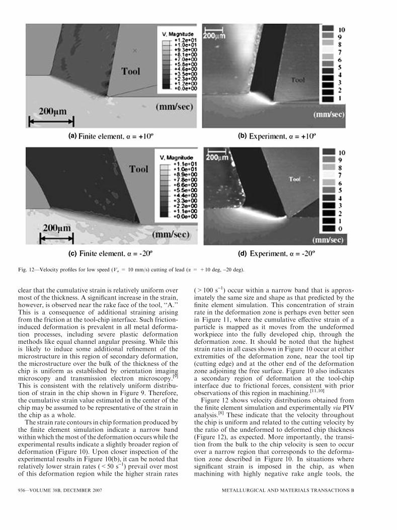
The strain rate contours in chip formation produced bythe finite element simulation indicate a narrow bandwithinwhich themost of the deformation occurs while theexperimental results indicate a slightly broader region ofdeformation (Figure 10). Upon closer inspection of theexperimental results in Figure 10(b), it can be noted thatrelatively lower strain rates (<50 s-1) prevail over mostof this deformation region while the higher strain rates
(>100 s-1) occur within a narrow band that is approx-imately the same size and shape as that predicted by thefinite element simulation. This concentration of strainrate in the deformation zone is perhaps even better seenin Figure 11, where the cumulative effective strain of aparticle is mapped as it moves from the undeformedworkpiece into the fully developed chip, through thedeformation zone. It should be noted that the higheststrain rates in all cases shown in Figure 10 occur at eitherextremities of the deformation zone, near the tool tip(cutting edge) and at the other end of the deformationzone adjoining the free surface. Figure 10 also indicatesa secondary region of deformation at the tool-chipinterface due to frictional forces, consistent with priorobservations of this region in machining.[11,10]
Figure 12 shows velocity distributions obtained fromthe finite element simulation and experimentally via PIVanalysis.[8] These indicate that the velocity throughoutthe chip is uniform and related to the cutting velocity bythe ratio of the undeformed to deformed chip thickness(Figure 12), as expected. More importantly, the transi-tion from the bulk to the chip velocity is seen to occurover a narrow region that corresponds to the deforma-tion zone described in Figure 10. In situations wheresignificant strain is imposed in the chip, as whenmachining with highly negative rake angle tools, the
Fig. 12—Velocity profiles for low speed (Vo = 10 mm/s) cutting of lead (a = +10 deg, -20 deg).
936—VOLUME 38B, DECEMBER 2007 METALLURGICAL AND MATERIALS TRANSACTIONS B

friction forces the chip material adjacent to the tool rakeface to ‘‘stick’’ to this face. For some rake angles, thisstuck material may be seen as a small extension of thetool tip (Figure 12, a = -20 deg), where the adjoiningmaterial bypasses the ‘‘stuck’’ material by plasticallyflowing around it. This stuck region of ‘‘dead metal’’allows material to build up ahead of the tool tip; the deadmetal region is commonly referred to as a built-up edgein machining.[12] Figure 13(a) shows a particularlyextreme example of the formation of a dead metal regionwhen cutting with a -50 deg rake angle tool. The finiteelement simulation predicts infeasibility of continuouschip formation for this condition and instead a pileup ofwork material ahead of the tool tip. This rake angle maybe identified as the critical rake angle below which nochip formation is possible. Such a lack of chip formationhas indeed been observed in plane strain machining oflead under similar conditions (Figure 13(b)).
IV. CONCLUDING REMARKS
The finite element model of machining described hereis a key element in establishing plane strain machining asa controlled method of severe plastic deformation andas a process for making ultra-fine-grained materials. Bycharacterizing the dependence of the shear strains andstrain rates in the deformation zone, on the tool rakeangle and friction at the tool-chip interface, an impor-tant step has been taken in relating the machining inputparameters to the deformation parameters (e.g., strainand strain rate). Such a correlation is necessary for
establishing machining as an experimental framework inwhich to systematically study the manifold and interac-tive effects of large strain deformation (e.g., strain andstrain rate) on microstructure and properties of mate-rials. A comparison of shear strains and their distribu-tions in the deformation zone estimated using the finiteelement model with direct measurements of these strainfields in plane strain machining has shown more thanreasonable agreement, with further validation studies inprogress. The simulation has also shown that the strainfield can be varied over a wide range by appropriatecontrol of machining input parameters. Taken together,these results establish the feasibility of machining as arobust and efficient method of severe plastic deforma-tion even for difficult-to-deform materials at ambienttemperature. Finally, the finite element simulation hasprovided a characterization of some machining condi-tions that inhibit chip formation; this prediction is againfound to be consistent with direct observations of chipformation.Prior studies of microstructure of machining chips
have confirmed the occurrence of nanoscale andultra-fine-grained microstructures and their specificdependence on deformation field parameters. By incor-porating microstructure-based models into our currentmodel of mechanics of large strain deformation in chipformation, it will likely be feasible to predict the rightcombinations of parameters needed to create ultra-fine-grained alloys with desired microstructure and proper-ties. The mechanics of microstructure evolution atdifferent length scales could then also be elucidated.These, together with refinement of our present finiteelement model to include temperature influences, offermuch scope for further study.
ACKNOWLEDGMENTS
We acknowledge NASA GSRP Fellowship No.NND04CR12H and NSF Grant Nos. CMS-0200509,CMMI-0626047 and CMMI-0626541 in support ofthis work. We also thank Dr. Srinivasan Swaminathan,Naval Post Graduate School (Monterrey, CA), previ-ously at Purdue, for his contributions to this work.
REFERENCES1. R.Z. Valiev, A.V. Korznikov, and M.M. Mulyukov: Mater. Sci.
Eng. A, 1993, vol. 168, pp. 141–48.2. F.J. Humphreys, P.B. Prangnell, J.R. Bowen, A. Gholinia, C.
Harris, J. Gil Sevillano, C. Garcia-Rosales, and J. Flaquer-Fuster:Philos. Trans. R. Soc. London, Ser. A, 1999, vol. 357, pp. 1663–81.
3. M. Furukawa, Z. Horita, M. Nemoto, and T.G. Langdon: J.Mater. Sci., 2001, vol. 36, pp. 2835–43.
4. J.D. Embury and R.M. Fisher: Acta Metall., 1966, vol. 14, pp.147–59.
5. G. Langford andM.Cohen:Trans. ASM, 1969, vol. 62, pp. 623–38.6. V.M. Segal, V.I. Reznikov, A.E. Drobyshevskiy, and V. Kopylov:
Russ. Metall., 1981, vol. 1, pp. 99–105.7. T.L. Brown, S. Swaminathan, S. Chandrasekar, W.D. Compton,
A.H. King, and K.P. Trumble: J. Mater. Res., 2002, vol. 17, pp.2484–88.
8. M. Ravi Shankar, B.C. Rao, S. Lee, S. Chandrasekar, A.H. King,and W.D. Compton: Acta Mater., 2006, vol. 54, pp. 3691–3700.
Fig. 13—The buildup of stagnant dead metal at the tool tip fora = -50 deg.
METALLURGICAL AND MATERIALS TRANSACTIONS B VOLUME 38B, DECEMBER 2007—937
9. S. Swaminathan, T.L. Brown, S. Chandrasekar, T.R. McNelley,and W.D. Compton: Scripta Mater., 2007, vol. 56, pp. 1047–50.
10. S. Lee, J. Hwang, M. Ravi Shankar, S. Chandrasekar, and W.D.Compton: Metall. Mater. Trans. A, 2006, vol. 37, pp. 1633–43.
11. M.C. Shaw: Metal Cutting Principles, Oxford University Press,Oxford, United Kingdom, 1984.
12. P.L.B. Oxley: The Mechanics of Machining: An AnalyticalApproach to Assessing Machinability, John Wiley & Sons, NewYork, NY, 1989.
13. S. Kobayashi and E.G. Thomsen: J. Eng. Ind., 1960, vol. 81,pp. 251–62.
14. P.V. Desai and S. Ramalingam: J. Eng. Ind., 1981, vol. 103,pp. 79–80.
15. B.E. Klamecki: Ph.D. Thesis, University of Illinois at Urbana–Champaign, Urbana, IL, 1973.
16. T. Shirakashi and E. Usui: Proc. Int. Congr. Prod. Eng., Tokyo,1974, pp. 535–40.
17. J.S. Strenkowski and J.T. Carroll: J. Eng. Ind., 1985, vol. 107,pp. 349–54.
18. K. Iwata, K. Oskada, and Y. Terasaka: J. Eng. Mater. Technol.,1974, vol. 106, pp. 132–38.
19. A.J.M. Shih, S. Chandrasekar, and H.T.Y. Yang: ASME Pub.PED, 1990, pp. 11–24.
20. K. Komvopoulos and S.A. Erpenbeck: J. Eng. Ind., 1991, vol. 113,pp. 253–67.
21. Z.C. Lin, K.T. Chu, and W.C. Pan: J. Mater. Process. Technol.,1994, vol. 41, pp. 291–310.
22. B. Zhang and A. Bagchi: J. Eng. Ind., 1994, vol. 116, pp. 289–97.23. H. Ernst: Machining of Metals, American Society of Metals,
Cleveland, OH, 1938.24. I. Finnie: Mech. Eng., 1956, vol. 78, pp. 715–21.25. A.J.M. Shih: Int. J. Mech. Sci., 1996, vol. 38, pp. 1–17.26. J.T. Carroll and J.S. Strenkowski: Int. J. Mech. Sci., 1988, vol. 30,
pp. 899–920.27. G.S. Sekhon and J.L. Chenot:Eng. Comp., 1993, vol. 10, pp. 31–48.28. I.S. Jawahir, A.K. Balaji, R. Stevenson, and C.A. van Luttervelt:
Symp. Predictable Modeling in Metal Cutting as Means of
Bridging Gap between Theory and Practice, ManufacturingScience Technology, American Society of Mechanical Engineers(ASME) International Mechanical Engineering Conference andExposition (IMECE), ASME, New York, NY, MED-6-2, 1997,pp. 3–12.
29. C.A. van Luttervelt , T. Childs, I.S. Jawahir, and F. Klocke: Ann.CIRP, 1998, vol. 47, pp. 587–626.
30. E. Ceretti, P. Fallbohmer, W.T. Wu, and T. Altan: J. Mater.Process. Technol, 1996, vol. 59, pp. 169–80.
31. A. Simoneau, E. Ng, and M.A. Elbestawi: Ann. CIRP, 2006,vol. 55, pp. 97–102.
32. E. Uhlmann, M. Graf von der Schulenburg, and R. Zettier: Ann.CIRP, 2007, vol. 56, pp. 61–64.
33. T.D. Marusich and M. Ortiz: Int. J. Num. Meth. Eng., 1995,vol. 38, pp. 3675–94.
34. V. Madhavan, S. Chandrasekar, and T.N. Farris: J. Appl. Mech.,2000, vol. 67, pp. 128–39.
35. J. Hashemi and R. Stefan: Recent Advances in StructuralMechanics, American Society of Mechanical Engineers (ASME),Pressure Vessels and Piping Conference (PVP), ASME, New York,NY, 1994, vol. 295, pp. 113–25.
36. L. Olovsson, L. Nilsson, and K. Simonsson: Comput. Struct.,1999, vol. 72, pp. 497–507.
37. M.R. Movahhedy, M.S. Gadala, and Y. Altintas: Mach. Sci.Technol., 2000, vol. 4, pp. 15–42.
38. M. Sevier, S. Lee, M.R. Shankar, H.T.Y. Yang, S. Chandrasekar,and W.D. Compton: Mater. Sci. Forum, 2006, vols. 503–504,pp. 379–84.
39. I.C. Taig: English Electric Aviation Report, S017, England, 1961.40. D.P. Flanagan and T. Belytschko: Int. J. Num. Meth. Eng., 1981,
vol. 17, pp. 679–706.41. M. Kleiber: Incremental Finite Element Modeling in Non-Linear
Solid Mechanics, John Wiley & Sons, New York, NY, 1989.42. ABAQUS: ABAQUS Theory Manual, Version 6.5, Hibbitt,
Karlsson & Sorenson, Inc, Pawtucket, RI, 2004.43. D.J. Benson: Comp. Meth. Appl. Mech. Eng., 1989, vol. 72,
pp. 305–50.
938—VOLUME 38B, DECEMBER 2007 METALLURGICAL AND MATERIALS TRANSACTIONS B