![Stylus System Changer Set-up Procedures for Zeiss …...[Type text] [Type text] [Type text] Tool Changer Page 1 of 23 Stylus System Changer Set-up Procedures for Zeiss CMMs Table of](https://static.fdocuments.net/doc/165x107/5e6d26f83912ef023b4ec125/stylus-system-changer-set-up-procedures-for-zeiss-type-text-type-text-type.jpg)
Setting Up Your Tool Changer - CNC Controls and CNC Kits … Up Your T… · ·...
14
MachMotion Version 1.0.1 MACHMOTION Setting Up Your Tool Changer Using Automation Direct PLCs 12/18/2010 Everything you need to know to setup a tool changer with your Automation Direct PLC.
Transcript of Setting Up Your Tool Changer - CNC Controls and CNC Kits … Up Your T… · ·...
MachMotion Version 1.0.1
MACHMOTION
Setting Up Your Tool Changer
Using Automation Direct PLCs
12/18/2010
Everything you need to know to setup a tool changer with your Automation Direct PLC.

2 | P a g e
Copyright © 2010, MachMotion.com All rights reserved.
MachMotion.com http://www.machmotion.com 14518 County Road 7240, Newburg, MO 65550 (573) 368-7399 • Fax (573) 341-2672
3 | P a g e
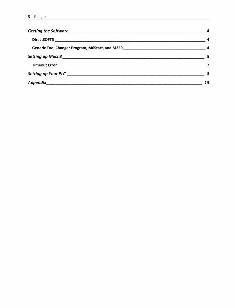
Getting the Software __________________________________________________________ 4
DirectSOFT5 _______________________________________________________________________ 4
Generic Tool Changer Program, M6Start, and M250 _______________________________________ 4
Setting up Mach3 _____________________________________________________________ 5
Timeout Error ______________________________________________________________________ 7
Setting up Your PLC ___________________________________________________________ 8
Appendix ___________________________________________________________________ 13
4 | P a g e
Getting the Software
The following files and software are needed for this tool changer to function properly:
DirectSOFT 5
Generic Tool Changer Program
M6Start and M250
DirectSOFT5 Begin by downloading DirectSOFT 5 from http://ftp.automationdirect.com/pub/DSP_53_SP.exe . You
can also go to www.automationdirect.com and find the software yourself.
This is a free demo which limits your program to 100 rungs. Currently only 37 rungs are used in the PLC
in the example tool changer program. If your tool changer is quite extensive, you may need to consider
purchasing the software directly from Automation Direct.
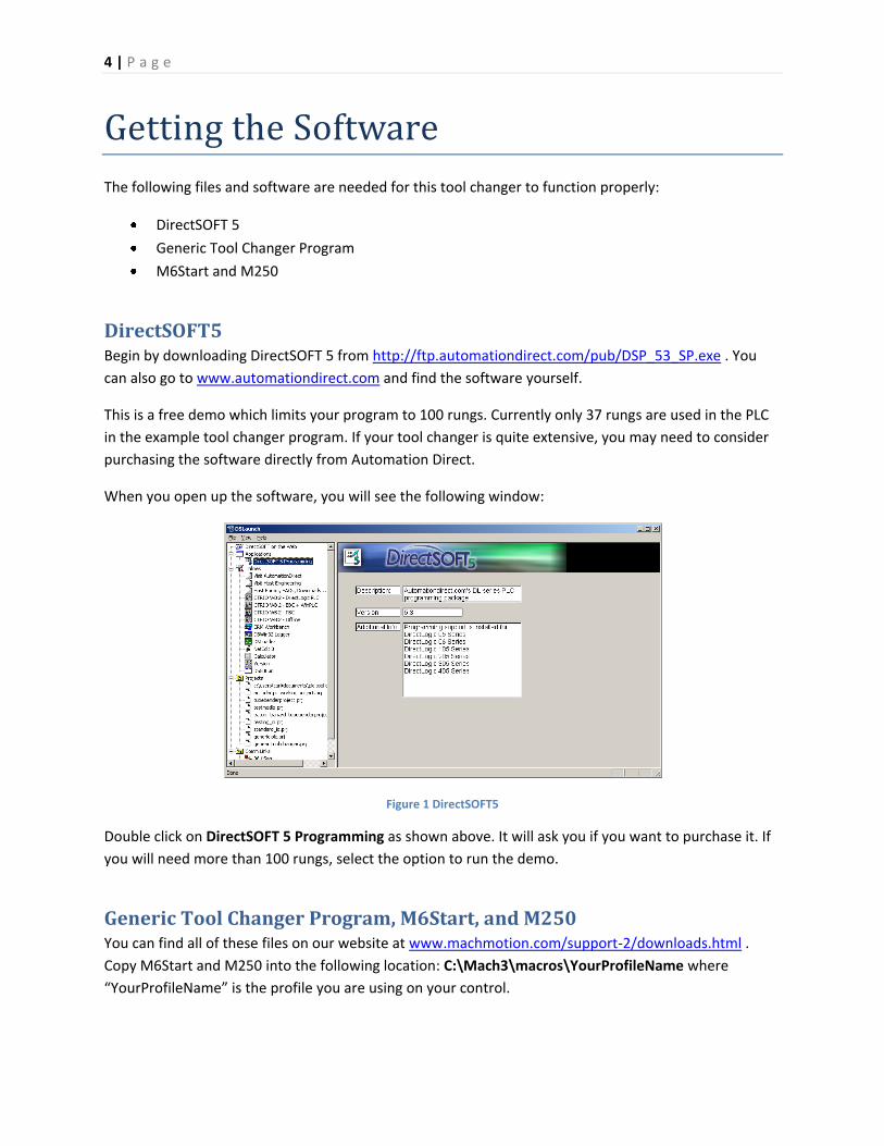
When you open up the software, you will see the following window:
Figure 1 DirectSOFT5
Double click on DirectSOFT 5 Programming as shown above. It will ask you if you want to purchase it. If
you will need more than 100 rungs, select the option to run the demo.
Generic Tool Changer Program, M6Start, and M250 You can find all of these files on our website at www.machmotion.com/support-2/downloads.html .
Copy M6Start and M250 into the following location: C:\Mach3\macros\YourProfileName where
“YourProfileName” is the profile you are using on your control.

5 | P a g e
Setting up Mach3
To setup your tool changer, begin by configuring Mach3.
1. Start the Mach3 software.
2. Open up the the serial modbus control. Select Function Cfg’s from the menu bar and then
click on Setup Serial Modbus Control as shown below.
Figure 2 Setup Serial ModBus
You will see the ModBus Configuration window (Figure 3).
3. The following configuration in the modbus window must be used (Figure 3). Notice that at
least 7 inputs and 6 outputs must be transferred between Mach3 and the PLC. For more
information on addressing in a PLC, see our manual Programmable Logic Controls: Using
ModBus to Interface PLCs with Mach3.
Figure 3 ModBus Configuration

6 | P a g e
4. From the menu bar select Config, then press General Config…
Figure 4 General Config
The following window will appear:
Figure 5 General Logic Configuration
5. Select Auto Tool Changer on the far left of the window.
Figure 6 Auto Tool Changer

7 | P a g e
6. In the Initialization String box, add “,M250” to the current text. This will run the
initialization macro when the control turns on.
Figure 7 Initialization String
7. Then press OK and the General Logic Configuration window will close.
Mach3 is now configured to interface with your PLC.
Timeout Error If the control tells the PLC to change tools and B1200.15 stays on for longer than 20 seconds, the control
will give you the following timeout error: "Tool Change is not Complete."
To change this timeout value, select Operator and then VB Script Editor. Open M6Start which will be
found in C:\Mach3\Macros\YourProfileName.
Change the variable TimeOut to whatever you want.
Figure 8 Change the TimeOut Value

8 | P a g e
Setting up Your PLC
With Mach3 setup, it is time to configure your PLC.
1. Open the Generic Tool Changer project in DirectSOFT 5. Click File on the menu bar and then
select Open Project.
Figure 9 Open Project
You should see the following:
Figure 10 Generic Tool Changer

9 | P a g e
2. Enter in your maximum number of tools. Press the red button called EDIT MODE to be able to
change the program.
Figure 11 Max Number of Tools
The above example only uses 8 tools.
3. Add more initialization rungs for however many tools are needed. The tool changer initialization
that tells your control what tool is currently loaded. Rungs 2-9 load the current tool position into
register V1205. This value is used to reference your control with your tool changer when the
control first turns on.
Figure 12 Find Current Tool
As shown above, depending on what input is active, the PLC knows what position the tool changer is
in. Just copy the existing rungs to add another one. Notice that is routine is only run during the first
scan. From then on, the only way to change the tool position is to receive an actual command from
your control.

10 | P a g e
4. Depending on how many tools are needed, copy the existing example of the of the tool changer
start rungs.
Figure 13 Start Rungs
The V memory location V1405 is the commanded tool from your control. When the M6Start
macro is run in Mach3, it turns on B1400.15 for 500ms. That turns on B1200.15 which tells your
control that the tool changer is currently changing the part. As long as the commanded tool and
the current tool are different and the start command is received (B1400.15), the coil
corresponding to the commanded tool will turn on for one cycle (PD). B1200.15 also starts the
tool changer routine.
To add another tool, copy the rung for tool 8. Change the constant that V1405 is compared with
and the coil that it turns on.
5. Program your specific tool changer. Each tool has a specific coil that is turned on for one PLC
scan. This coil starts your tool changer.
11 | P a g e
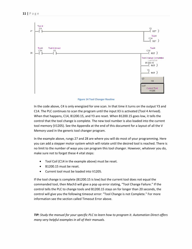
Figure 14 Tool Changer Routine
In the code above, C4 is only energized for one scan. In that time it turns on the output Y3 and
C14. The PLC continues to scan the program until the input X3 is activated (Tool 4 Arrived).
When that happens, C14, B1200.15, and Y3 are reset. When B1200.15 goes low, it tells the
control that the tool change is complete. The new tool number is also loaded into the current
tool memory (V1205). See the Appendix at the end of this document for a layout of all the V
Memory used in the generic tool changer program.
In the example above, rungs 27 and 28 are where you will do most of your programming. Here
you can add a stepper motor system which will rotate until the desired tool is reached. There is
no limit to the number of ways you can program this tool changer. However, whatever you do,
make sure not to forget these 4 vital steps:
Tool Coil (C14 in the example above) must be reset.
B1200.15 must be reset.
Current tool must be loaded into V1205.
If the tool change is complete (B1200.15 is low) but the current tool does not equal the
commanded tool, then Mach3 will give a pop up error stating, “Tool Change Failure.” If the
control tells the PLC to change tools and B1200.15 stays on for longer than 20 seconds, the
control will give you the following timeout error: "Tool Change is not Complete." For more
information see the section called Timeout Error above.
TIP: Study the manual for your specific PLC to learn how to program it. Automation Direct offers
many very helpful examples in all of their manuals.

12 | P a g e
6. Add more tool change routine rungs if more tools are needed. After you have one rung
programmed for your machine, it might be easiest just to copy it multiple times and then make
the changes for each specific tool.
Figure 15 Adding More Routines
Underneath the 8th tool routine, you can add as many tools as you need.
****************************************************************************
WARNING
Your program will not run without an END statement.
****************************************************************************

13 | P a g e
Appendix
These tables show the allocation of V memory V1400-1406 and V1200-V1206.
PLC Inputs PLC Outputs V Memory Function V Memory Function
V1400 Status Register V1200 Status Register
V1401 Reserved for I/O V1201 Reserved for I/O
V1402 Reserved for I/O V1202 Reserved for I/O
V1403 Reserved for I/O V1203 Reserved for I/O
V1404 Reserved for I/O V1204 Reserved for I/O
V1405 Commanded Tool V1205 Current Position
V1406 Unused V1206 Max Number of Tools
Below is the layout of each bit in the output status register V1200.
V1200 Status Register Function Active Low
Bit 0 Communication Check
Bit 1 N.C. Bit 2 N.C.
Bit 3 N.C.
Bit 4 N.C.
Bit 5 N.C.
Bit 6 N.C.
Bit 7 N.C.
Bit 8 N.C.
Bit 9 N.C.
Bit 10 N.C.
Bit 11 N.C.
Bit 12 N.C.
Bit 13 N.C.
Bit 14 N.C.
Bit 15 Finished Moving Low

14 | P a g e
Below is the layout of each bit in the input status register V1400.
V1400 Status Register Function Active Low
Bit 0 Communication Check
Bit 1 Emergency Stop Low
Bit 2 N.C.
Bit 3 N.C.
Bit 4 N.C.
Bit 5 N.C.
Bit 6 N.C.
Bit 7 N.C.
Bit 8 N.C.
Bit 9 N.C.
Bit 10 N.C.
Bit 11 N.C.
Bit 12 N.C.
Bit 13 N.C.
Bit 14 N.C.
Bit 15 Start Moving High


![Stylus System Changer Set-up Procedures for Zeiss CMMs · · 2014-10-29Type text] [Type text] [Type text] Tool Changer Page 5 of 12 4. Open the Automatic Stylus System Changer and](https://static.fdocuments.net/doc/165x107/5b0163557f8b9ad85d8e0e2b/stylus-system-changer-set-up-procedures-for-zeiss-cmms-text-type-text-type-text.jpg)