
Setting Up an MPI Connection with Siemens SIMATIC … Notes...Tech Note 303 Setting Up an MPI...
43
Tech Note 303 Setting Up an MPI Connection with Siemens SIMATIC NET 6.0 Software Using a CP5611 Profibus Card and an S7-400 PLC (CPU 413-1) All Tech Notes and KBCD documents and software are provided "as is" without warranty of any kind. See the Terms of Use for more information. Topic: 001110 Created: March 2003 This Tech Note outlines how to set up an MPI connection with Siemens SIMATIC NET 6.0 software using a CP5611 Profibus Card and an S7-400 PLC (CPU 413-1). Before You Get started, Please Do the Following: 1. Install the Siemens CP5611 adapter card part number (6GK15611AM00 - CP5611 + MPI-cable ) on your pc. The following are part numbers for the CP5611 separately: 6GK1561-1AA00 - SIMATIC NET, PB, CP 5611 PCI CARD (32 BIT) FOR CONNECTION OF A PG OR PC WITH PCI BUS TO PROFIBUS OR MPI 6GK1561-1AM00 - SIMATIC NET, PB, CP 5611-MPI CONS. OF: PCI CARD CP 5611 (32BIT) F. CONN. OF PC/PG WITH PCI BUS TO PROFIBUS OR MPI INCL. MPI CABLE, 5 M 2. Install the Siemens SIMATIC NET 6.0 Software + SP2 or higher. 3. Install the MPI cable (Connect it from the CP5611 adapter card to the MPI port on the CPU of the S7.) Siemens part number (6ES7901-0BF00-0AA0). 4. Install the Wonderware Siemens S7 I/O Server version 7,5,0,11. 5. Make sure that the S7 Plc is connected via the MPI cable to the pc and is in Run mode. Starting a new Project with SIMATIC Manager 1. Click on File/New from the SIMATIC Manager main menu. The following screen appears:
Transcript of Setting Up an MPI Connection with Siemens SIMATIC … Notes...Tech Note 303 Setting Up an MPI...
Tech Note 303
Setting Up an MPI Connection with Siemens SIMATIC NET 6.0 Software
Using a CP5611 Profibus Card and an S7-400 PLC (CPU 413-1)
All Tech Notes and KBCD documents and software are provided "as is" without warranty of any kind. See the Terms of Use
for more information.
Topic: 001110
Created: March 2003
This Tech Note outlines how to set up an MPI connection with Siemens SIMATIC NET 6.0 software
using a CP5611 Profibus Card and an S7-400 PLC (CPU 413-1).
Before You Get started, Please Do the Following:
1. Install the Siemens CP5611 adapter card part number (6GK15611AM00 - CP5611 + MPI-cable )
on your pc.
The following are part numbers for the CP5611 separately:
6GK1561-1AA00 - SIMATIC NET, PB, CP 5611 PCI CARD (32 BIT) FOR CONNECTION OF A PG OR
PC WITH PCI BUS TO PROFIBUS OR MPI
6GK1561-1AM00 - SIMATIC NET, PB, CP 5611-MPI CONS. OF: PCI CARD CP 5611 (32BIT) F.
CONN. OF PC/PG WITH PCI BUS TO PROFIBUS OR MPI INCL. MPI CABLE, 5 M
2. Install the Siemens SIMATIC NET 6.0 Software + SP2 or higher.
3. Install the MPI cable (Connect it from the CP5611 adapter card to the MPI port on the CPU of the
S7.) Siemens part number (6ES7901-0BF00-0AA0).
4. Install the Wonderware Siemens S7 I/O Server version 7,5,0,11.
5. Make sure that the S7 Plc is connected via the MPI cable to the pc and is in Run mode.
Starting a new Project with SIMATIC Manager
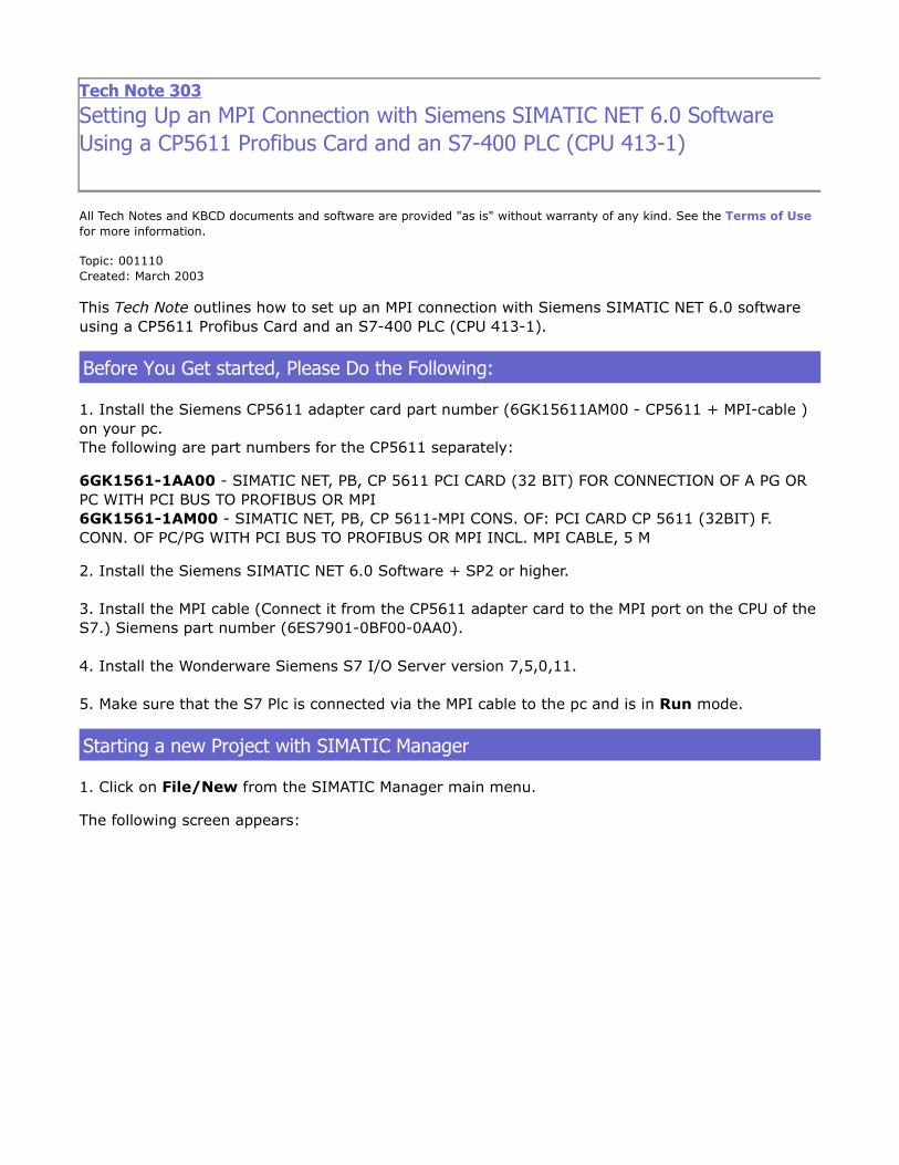
1. Click on File/New from the SIMATIC Manager main menu.
The following screen appears:
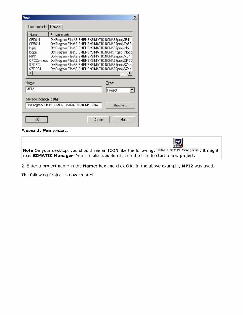
FIGURE 1: NEW PROJECT
Note On your desktop, you should see an ICON like the following: . It might
read SIMATIC Manager. You can also double-click on the icon to start a new project.
2. Enter a project name in the Name: box and click OK. In the above example, MPI2 was used.
The following Project is now created:

FIGURE 2: NEW PROJECT
3. Select Insert/Station/SIMATIC PC Station (see following figure) from the main menu:
FIGURE 3: INSERT...PC STATION

4.Highlight SIMATIC PC Station, right-click, and select Rename. Enter PCStation (following
figures) as the new name:
FIGURE 4: RENAME
Note The PCStation name MUST must match up with the name in the Station Configuration Editor
(see Figure 51).

FIGURE 5: PCSTATION
5. Highlight and expand the MPI2 icon. The following window appears:
FIGURE 6: CONFIGURATION ICON

6. Double-click the Configuration Icon in the right pane of the above figure to open up the
SIMATIC Manager PC Config screen. This enables the PCStation setup.
Setting up the PCStation in the SIMATIC Manager PC Config Screen
The following window should now be visible:
FIGURE 7: PCCONFIGURATION WINDOW
1. Add the Application component of the PCStation by selecting it in the right hand pane of the
PC Config window. In the previous figure, it appears under User Application. Drag it over to the
the top left box labeled (0) PC, and drop in the first line in order to configure the Application
component as Index 1 (see following figure):
FIGURE 8: INDEX 1
2. Select the CP 5611 module (under the CP Profibus folder), and drag it to the second line of the

(0) PC box. This creates Index 2 for the CP5611 component in the PCStation (see following
figure):
FIGURE 9: CP 5611 (RO/S2) DIALOG BOX
3. Click OK. The following figure shows the CP 5611 in index 2:
FIGURE 10: ITEM 2 - CP5611
4. Double click the CP5611 module that you just added to Index 2. The following dialog box
appears:

FIGURE 11: SELECT INTERFACE TYPE: DIALOG
5. In the Interface Type: area (shown above), open the Type: drop-down list and select MPI.
6. Click OK. The following message appears:
FIGURE 12: OBJECT PROPERTIES MESSAGE
7. Click Yes. The Properties - CP 5611 dialog box reappears.
8. Click Properties (see following figure):

FIGURE 13: PROPERTIES - CP 5611 DIALOG BOX
The MPI interface dialog box appears (following figure):
9. Click New (following figure):
FIGURE 14: NEW INTERFACE SETTING (CAPTION)
Note We will change the Bus address to correspond to the actual Bus address of the CP5611 card

in a subsequent step.
The New subnet MPI dialog box appears:
FIGURE 15: MPI CONFIGURATION
10. Select the Network Settings tab (see following figure):
FIGURE 16: PROPERTIES/NETWORK SETTINGS TAB
11. Select the Transmission rate:. For this test, 187.5 kbps is selected.
Note Your MPI Cable should have the baud rate printed on it.

12. Click OK.
Note The correct address of the CP5611 adapter card MUST be selected for the MPI interface. In
this example, it is 0. Settings are configured and verified from within the Configuration Console.
MPI Bus addresses are verified by running Start/Simatic/SIMATIC NET/
Settings/Configuration Console: (if the Wizard appears, click Cancel to return to the
Configuration Console window). The following figure shows the Configuration Console screen: node
0 is the CP5611 adapter card, and the CPU is 3:
FIGURE 17: CONFIGURATION CONSOLE INTERFACE
13. Next, select the correct address of the CP5611 in the Properties - MPI interface dialog:

FIGURE 18: ADDRESS LIST
FIGURE 19: ADDRESS SELECTED
14. Click OK (on both the MPI Interface and CP 5611 dialogs) to save the configuration and exit
the dialog boxes.
Your PC Config of PCStation should now look like the following figure:
FIGURE 20: PC CONFIG COMPLETED
15. (Optional) Adding the OPC Server component to the PC Config PCStation: Under the User
Application folder in right-hand pane of the PC Config window, select the OPC Server component
and drag it over to line 3 in the (0) PC pane. This creates the OPC Server as Index 3. The PC Config
PCStation window should now look like the following figure:

FIGURE 21: SELECT OPC SERVER
16. Click Station, then Save and Compile, to check for errors in your
configuration (see following figure):
FIGURE 22: SAVE AND COMPILE

FIGURE 23: COMPILING PROGRESS
Your configuration in PC Config for PCStation should now be complete.
Verifying Your Configuration in NetPro, and Creating Connections for the CP 5611 MPI
- and OPC Server.
1. Select Options/Configure Network from the main menu to start NetPro (see following figure):
FIGURE 24: START NETPRO
The following NetPro Window displays your current PCStation configuration without any connections
to the CP5611 module or the OPC Server components:

FIGURE 25: NETPRO WINDOW
2. Highlight the Application index in the PCStation box (see previous figure) to display the
connection window. Right-click the first row in the connection window and select Insert New
Connection:
FIGURE 26: INSERT NEW CONNECTION

The following dialog box appears:
FIGURE 27: INSERT NEW CONNECTION DIALOG BOX (DEFAULT SELECTIONS)
3. Select Unspecified from the Station drop down list, then S7 connection from the Connection
Type: drop-down list (see following 3 figures):
FIGURE 28: STATION: UNSPECIFIED
FIGURE 29: CONNECTION: S7 CONNECTION

FIGURE 30: CONNECTION CONFIGURED
4. Click Apply. (The OK button changes to Close).
The Properties - S7 dialog box appears:
FIGURE 31: S7 CONNECTION PROPERTIES
Note The three fields in Figure 29 labled Local ID, Partner, and Partner Address are very
important. You need to input the correct information.
In the following figure, notice that the Partner address is 3 and corresponds to the Bus addresses
found in the test that was run in the Configuration Console earlier in this technote. In this example,
the LocalID: will be MPI1and the Partner End point: will be MPI.

FIGURE 32: LOCAL ID, PARTNER FIELDS
5. Click the Address Details button. The following dialog box appears:
FIGURE 33: ADDRESS DETAILS DIALOG BOX
Note The connection resource is automatically assigned by SIMATIC NET when you add a new
connection, so leave the default value. It is very important that the Partner Rack/Slot value be
correct. Since the MPI port is on the CPU module, it is likely to be 3. Use the slot number of the
CPU for this entry.
The CPU in our example is located in slot 3, so that is what is entered (see following figure):

FIGURE 34: MPI RACK/SLOT: SETTINGS
6. Click OK twice to exit the dialog boxes. The Insert New Connection dialog box should now be
visible:
FIGURE 35: INSERT NEW CONNECTION DIALOG BOX WITH CLOSE BUTTON
7. Click Close.
The main NetPro window should now be visible. The following figure shows the new connection in
the NetPro window:

FIGURE 36: MAIN NETPRO WINDOW CONNECTION DISPLAY
7. Save and compile your PCStation in NetPro by selecting Network/Save and Compile from the
main menu (see following figure):
FIGURE 37: SAVE AND COMPILE THE CONNECTION CONFIGURATION
Note Whenever you make changes to NetPro (i.e. add a new connection), you MUST Save and
Compile.
The following dialog box appears:
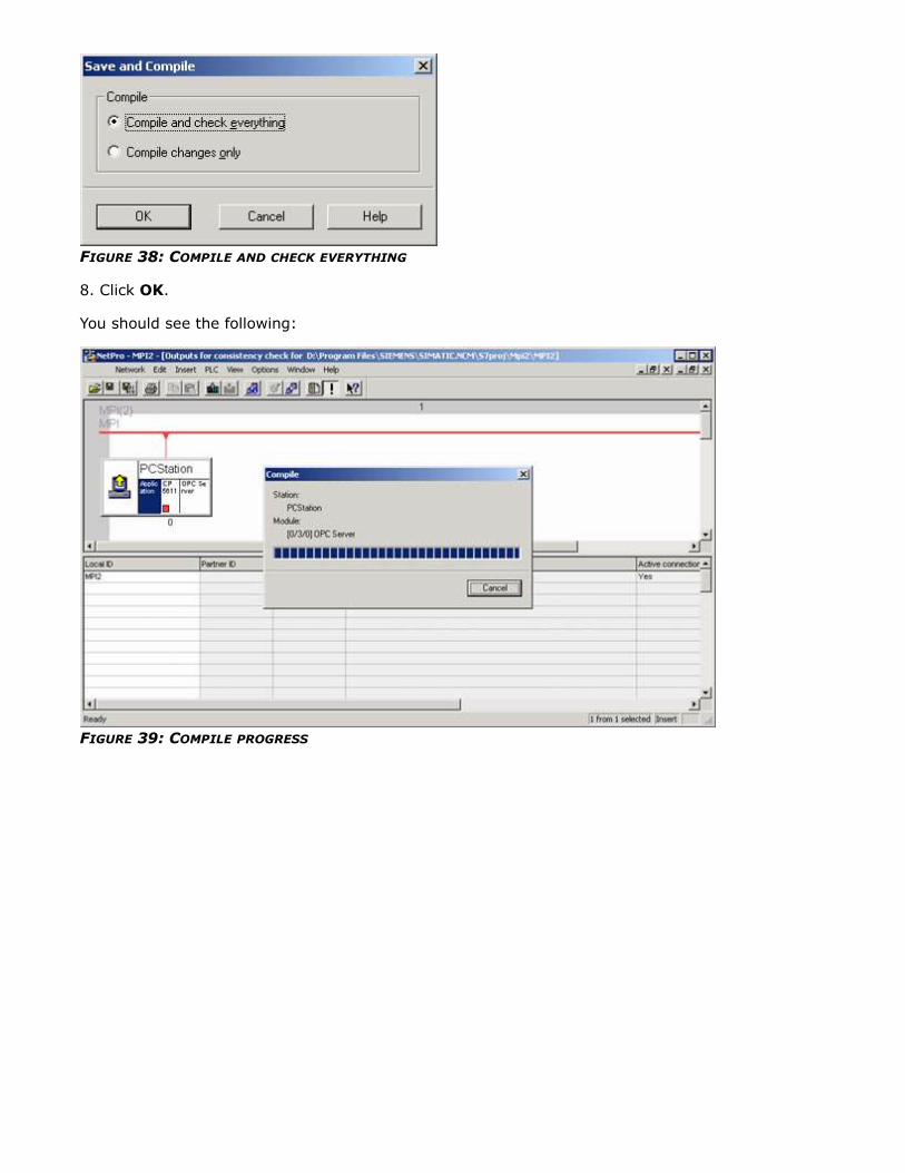
FIGURE 38: COMPILE AND CHECK EVERYTHING
8. Click OK.
You should see the following:
FIGURE 39: COMPILE PROGRESS

FIGURE 40: NO COMPILE ERRORS
(Optional) For an OPC Server Connection, repeat the steps 2 thru 7 (above) for the CP5611 OPC
connection.
In Step #2, click the OPC Server to highlight it instead of the Application. Then continue through
steps 3-7 to complete the configuration.
To see what the final NetPro configuration looks like, select Window from the main NetPro menu,
then select your project from the sub-menu (see following figure):

FIGURE 41: SELECT YOUR PROJECT
At this point your project is complete. The following figure shows two connections: one for the
Application CP5611 at Bus address 0, and the optional OPC Server connection:

FIGURE 42: OPC CONNECTION DISPLAY
Note If necessary, you can edit your S7 connections by double-clicking the blank cell under the
Partner ID column heading in the MPI2 row.
If you open your current project MPI2 in SIMATIC Manager , you will see the following screen. It
contains an overview of the PCStation in PC Config, and NetPro (see following figure):
FIGURE 43: CONNECTION OVERVIEW
Setting the Access Point Active in the SIMATIC NET Configuration Console

1. Start the Configuration Console (Start/Simatic/SIMATIC NET/Settings/Configuration
Console ).
Note 1: If you are running the Configuration Console for the first time, or if you switch your
PCStation from one module to another, (i.e., you setup a TCP/IP connection instead of an MPI) you
will likely see the Commissioning Wizard. If you have already set your access point to reflect
the current module, then you can cancel out of the Commissioning Wizard and continue to use the
Configuration Console. Even if you haven’t configured any access points in the Configuration
Console at the time you first open it, you can still click the Cancel button to continue making
manual configuration changes in the Configuration Console. Doing so is recommended for this
technote (see following figure):
FIGURE 44: CANCELLING THE WIZARD TO MAKE MANUAL CONFIGURATION CHANGES
Click Cancel and continue through Step 2 (below) after you see the Configuration console main
screen:
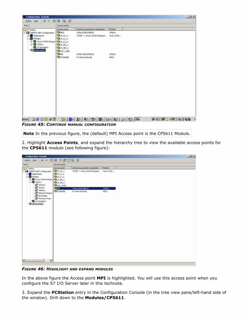
FIGURE 45: CONTINUE MANUAL CONFIGURATION
Note In the previous figure, the (default) MPI Access point is the CP5611 Module.
2. Highlight Access Points, and expand the hierarchy tree to view the available access points for
the CP5611 module (see following figure):
FIGURE 46: HIGHLIGHT AND EXPAND MODULES
In the above figure the Access point MPI is highlighted. You will use this access point when you
configure the S7 I/O Server later in this technote.
3. Expand the PCStation entry in the Configuration Console (in the tree view pane/left-hand side of
the window). Drill down to the Modules/CP5611.

4. In the General: Module properties pane, select Configuration mode from the drop-down list
as the mode of the module (see following figure):
FIGURE 47: SELECT THE MODULE MODE
5. After selecting the Mode of the module: to be Configuration mode, a selection for the Index
value appears.
6. Expand the drop-down list and select index 2, since it was configured in your S7 Project. Notice
that the Apply button becomes enabled (see following figure):

FIGURE 48: SELECT INDEX VALUE
7. Click Apply. The following dialog box appears:
FIGURE 49: CHANGE CONFIGURATION PROMPT
8. Click OK since you need to configure the PCStation in your project to use the CP 5611 module.
The following screen shows that the CP5611 module is now configured and ready for use with your
S7 project:

FIGURE 50: COMPLETED CONFIGURATION
You can now close the Configuration Console.
Configuring the Station Configuration Editor (It Appears in the System Tray, and it
Looks Like a Computer!)
1. Open the Station Configuration Editor. After setting the CP5611 to Configuration Mode, it will
automatically be added to the Station Configuration Editor as index 2 (see following figure):
Note The Station: name (PCStation) in the following figure is the same as the one entered in
Step 4 of Starting a New Project.
Return to Step 4
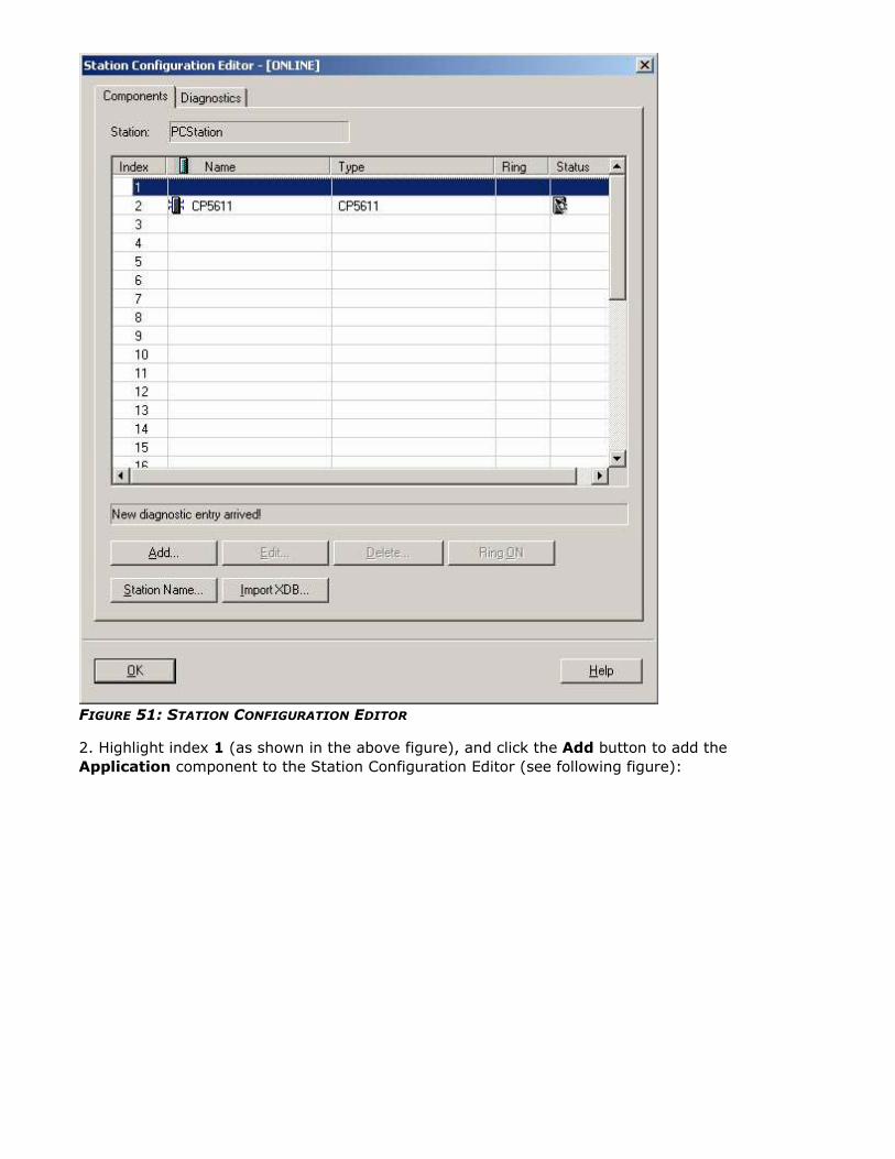
FIGURE 51: STATION CONFIGURATION EDITOR
2. Highlight index 1 (as shown in the above figure), and click the Add button to add the
Application component to the Station Configuration Editor (see following figure):

FIGURE 52: ADD COMPONENT
Note The configuration in the Station Configuration Editor should match up with the configuration
in NetPro. (i.e. index 1 – Application, index 2 – CP 5611, [optional:index 3 – OPC Server]).
3. Enter Application in the name field to match the component type (see following figure):
FIGURE 53: NAME APPLICATION COMPONENT
4. Click OK to add the Application component. The following pop up message will appear:

FIGURE 54: CHANGE CONFIGURATION MESSAGE
5. Click OK. The Station Configuration Editor should now display two components, Application as
index 1, and the CP 5611 as index 2 (see following figure):
FIGURE 55: APPLICATION AND CP5611 COMPONENTS
5. If required, repeat steps 2 thru 5 to add the OPC Server component as index 3 (see following
figure):

FIGURE 56: ADD OPC SERVER COMPONENT
6. The following figure shows the completed Station Configuration Editor window with all three
components from PCStation (Application, CP 5611, and OPC Server):

FIGURE 57: THREE PCSTATION COMPONENTS
Note the red X next to the Application and OPC Server rows in the above figure. This means that
the database is not updated.
You must now download the configuration from the the PCStation (Configuration) main window
and the NetPro interface (step 12 below).
7. The following figure shows downloading your current project configuration to the S7 CPU through
your MPI connection (PLC/Download):

FIGURE 58: DOWNLOAD THE PROJECT CONFIGURATION
8. When you select the Download command from the menu, the following pop up appears:
FIGURE 59: TARGET MODULE SELECTION
9. Click OK to select the four modules.
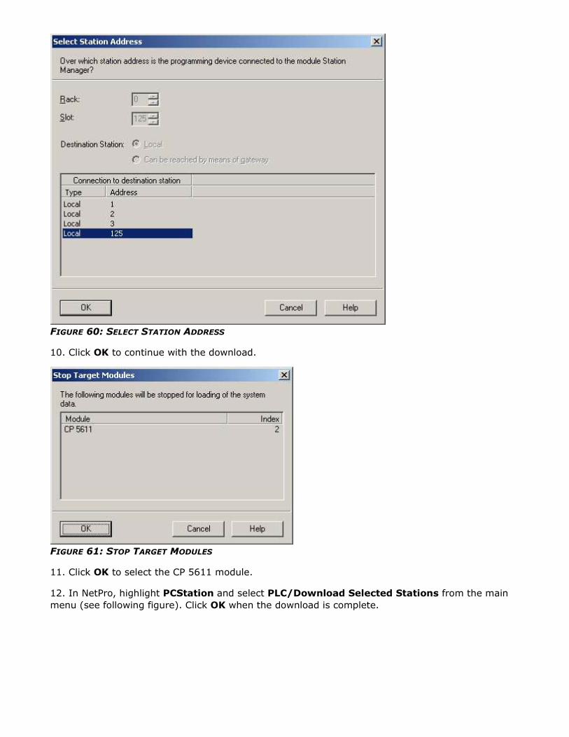
FIGURE 60: SELECT STATION ADDRESS
10. Click OK to continue with the download.
FIGURE 61: STOP TARGET MODULES
11. Click OK to select the CP 5611 module.
12. In NetPro, highlight PCStation and select PLC/Download Selected Stations from the main
menu (see following figure). Click OK when the download is complete.

FIGURE 62: DOWNLOAD SELECTED STATIONS
At this point, your SIMATIC NET configuration is complete. Proceed to the next section to configure
the S7 IOServer.
Configuring the S7 I/O Server
1. Start the S7 I/O Server. Select Configure/Topic Definition from the main menu (see following
figure):

FIGURE 63: CONFIGURE/TOPIC DEFINITION
A blank Topic Definition dialog box appears.
2. Click New to add the topic MPITEST or whatever you want to call your topic. After adding
MPITEST as your topic name, select MPI as your CP-Name, Application as the VFD, and MPI1 as
your connection.
Note If the VFD and Connection values don’t show up automatically, you might have done
something wrong in your S7 Project. Try re-starting the I/O Server and re-creating the topic, or
re-save and compile your configuration in the SIMATIC PC Config. section of SIMATIC Manager
(see following figure):
FIGURE 64: NEW TOPIC

3. Click OK to save the new topic.
FIGURE 65: NEW TOPIC DEFINITION
4. Click Done to exit the Topic Definition dialog box.
The S7 I/O Server configuration is now complete.
Testing Your S7 Configuration With wwClient
1. Start wwClient, select Connections/Create to create a new connection to the S7 ioserver (see
following figure):
FIGURE 66: CREATE A NEW CONNECTION

FIGURE 67: DDE CONNECTION
2. After entering the above information, click the Create button, and then Done. The following
figure shows the DDE connection to the S7 I/Oserver:
FIGURE 68: DDE CONNECTION
3. Click on Item, and the following window appears:

FIGURE 69: ITEM PROPERTIES
4. Enter in mb90 (or any valid item in the PLC) for the Item, and click the AdviseEx, and Done
buttons. The following figure shows a "good" value (0X00C0) counting on the second line of the
wwClient window:
FIGURE 70: WWCLIENT WINDOW
The following figure shows the S7 I/O Server window with the item mb90 on advise and a topic
status of GOOD, and 0 errors:

FIGURE 71: S7 I/O SERVER WINDOW
The following screen shows the S7 Data Monitor with the item MB90 with a good Quality value
(00C0).
FIGURE 72: S7 DATA MONITOR
You have successfully configured SIMATIC NET 6.0 to communicate to the Wonderware Siemens S7
IOServer.
D. Plesset
Tech Notes are published occasionally by Wonderware Technical Support. Publisher: Invensys Systems, Inc., 26561 Rancho
Parkway South, Lake Forest, CA 92630. There is also technical information on our software products at Wonderware

Technical Support.
For technical support questions, send an e-mail to [email protected].
back to top
©2002 Invensys Systems, Inc. All rights reserved. No part of the material protected by this copyright may be reproduced or
utilized in any form or by any means, electronic or mechanical, including photocopying, recording, broadcasting, or by any
information storage and retrieval system, without permission in writing from Invensys Systems, Inc. Terms of Use.