Set EHT Trip Level (for printhead setup...
72
Videojet 43s Inkjet Printer Service Manual Rev AC Set EHT Trip Level (for printhead setup only) 5-9 Set EHT Trip Level (for printhead setup only) Ensure that the printhead is clean and dry before setting the EHT range and trip level. The preliminary settings ensure that EHT trip is prevented when setting up the printhead and calibrating the EHT table. 1 Fit the printhead cover. 2 From the Calibrate menu select EHT Range Set. 3 Press . 4 Select EHT Value 1 and set the value to 255. 5 Select EHT Value 10 and set the value to 255. 6 Press to save the settings. 7 Fit the printhead cover. 8 From the Calibrate menu select EHT Trip Level Set. enter enter
Transcript of Set EHT Trip Level (for printhead setup...

Videojet 43s Inkjet Printer Service Manual
Rev AC Set EHT Trip Level (for printhead setup only) 5-9
Set EHT Trip Level (for printhead setup only)Ensure that the printhead is clean and dry before setting the EHT range and trip level. The preliminary settings ensure that EHT trip is prevented when setting up the printhead and calibrating the EHT table.
1 Fit the printhead cover.
2 From the Calibrate menu select EHT Range Set.
3 Press .
4 Select EHT Value 1 and set the value to 255.
5 Select EHT Value 10 and set the value to 255.
6 Press to save the settings.
7 Fit the printhead cover.
8 From the Calibrate menu select EHT Trip Level Set.
enter
enter

Videojet 43s Inkjet Printer Service Manual
5-10 Set EHT Trip Level (for printhead setup only) Rev AC
9 Press . The display shows “Setting EHT trip level.”
10 After approximately one minute the display changes to “EHT trip set successful.”
11 Press .
enter
enter

Videojet 43s Inkjet Printer Service Manual
Rev AC About the Low Fluid Indicators 5-11
About the Low Fluid IndicatorsThere are three low fluid indicators that appear on the display screen. They have the meanings shown below. See “Display Icons” on page 10-8 for additional troubleshooting information.
If the Mixer Tank Low icon is displayed, prime the mixer tank according to the instructions in “Fill Mixer Tank” on page 5-12.
Note: The Mixer Tank Low icon will clear from the display before all the ink is added to the mixer tank but ensure that the entire 250 ml of ink is added.
Caution
EQUIPMENT DAMAGE. Ensure that the ink comes from a sealed bottle and that at least one of the bottles from the same batch has been tested to ensure that the viscosity is correct.
If the Ink Level Low icon is displayed, fill the ink reservoir by adding ink at the black filler cap (4-slot spider). Normally, a full liter should be added. But, if you have just primed the mixer tank, use the remaining ink in the open bottle.
If the Top Up Level Low icon is displayed, add one liter of the appropriate top-up solvent at the white filler cap (3-slot spider).

Videojet 43s Inkjet Printer Service Manual
5-12 Fill Mixer Tank Rev AC
Fill Mixer TankIf the ink level in the mixer tank is less than 250 ml then it will be below the ink pick up pipe. The machine will not reach operating pressure or top up ink. If this is the case, begin at step 1, below. If there is more than 250 ml in the mixer tank, proceed to step 5.
Figure 5-4. Ink Mixer Tank and Filler Plug Location
1 Remove the filler plug (Item 2 in Figure 5-4) from the top of the FMS.
2 Prime the mixer bowl (3) with approximately 250 ml of the correct ink using a syringe and a length of 40 mm x 6 mm tube. The Ink Out icon will cease to be displayed when approximately 250 ml is added to the mixer bowl.
3 Ensure that the complete 250 ml is added before proceeding.
4 Refit the filler plug (2) to the top of the FMS.
(1) FMS tray(2) Filler plug(3) Mixer tank

Videojet 43s Inkjet Printer Service Manual
Rev AC Fill Mixer Tank 5-13
5 From the System menu select Fill Mixer Tank.
6 Press . The pump starts and the mixer tank fills. When the level of ink is OK, the pump stops (this may take several minutes).
enter

Videojet 43s Inkjet Printer Service Manual
5-14 Entering Fluid Information Rev AC
Entering Fluid InformationTo ensure that the printer has the correct information about the ink and top-up being used, proceed as follows:
1 From the Calibrate menu select Set Ink Type and press .
2 Check that the Fluid ID No. (FIN) displayed corresponds with ink and top-up being used with the machine. If the FIN, Ink Part No. and Top-up Part No. have previously been entered and are correct, press
.
If any of these numbers do not correspond with the ink and top-up being used with the machine, enter the correct values and press
.
Notes: Refer to the ink bottle for the correct FIN number.
FIN numbers should be entered exactly as they appear on the bottle. Do not alter the punctuation or add spaces anywhere.
Although the ink and top-up part numbers are not actually used in the operation of the machine, it is important to enter them anyway. The printer displays these values for the user when the corresponding fluid is low. Ideally, this will help avoid mishaps due to the addition of incorrect fluids.
enter
esc
esc

Videojet 43s Inkjet Printer Service Manual
Rev AC Manually Priming the Flush Pump 5-15
Manually Priming the Flush PumpIn some cases (occurs only rarely), air will remain trapped in the flush system even after a system flush/purge operation has been completed. This problem can sometimes by solved by manually priming the flush pump using the flush pump priming adapter (P/N 2000466246) and a syringe (P/N 5000118001) from the service tool kit.
1 Unscrew the tube fitting (Item 2 in Figure 5-5) from the end of the flush filter (1) nearest the flush pump (3).
Figure 5-5. Manually priming the flush pump
2 Unscrew the black omnifit connector (4) from the front of the flush pump. Place the connector and free tube end in a suitable fluid catcher to catch any ink that drains out.
3 Make sure the syringe plunger is fully inserted in the body of the syringe. Then, connect the flush pump priming adapter to the syringe.
4 Attach the other end of flush pump priming adapter to the flush pump.
5 Carefully draw the syringe plunger back until air bubbles begin to fill the priming adapter tube.
6 Disconnect the syringe from the tube just long enough to break the air seal between the two.
(1) Flush filter(2) Flush filter tube fitting(3) Flush pump(4) Black omnifit connector

Videojet 43s Inkjet Printer Service Manual
5-16 Manually Priming the Flush Pump Rev AC
7 Once the tube is re-connected to the syringe, carefully return the plunger to the fully inserted position. (Solvent should squirt out of the tube that was disconnected from the flush filter).
8 Re-attach the flush filter tube.
9 Disconnect the flush pump priming adapter and re-attach the black omnifit connector.

Videojet 43s Inkjet Printer Service Manual
Rev AC VMS Calibration 5-17
VMS Calibration
Caution
INCORRECT VISCOSITY. Do not perform this calibration unless Visc setpoint and Visc actual values displayed in the diagnostics screen differ by no more than 3.
Ensure that the ink comes from a sealed bottle and that at least one of the bottles from the same batch has been tested to ensure that the viscosity is correct.
1 Remove the electrical connections from the top-up addition valve (V1).
2 Start the jet by pressing . Ensure the that machine has been running for at least 20 minutes before continuing.
3 From the Calibrate menu select VMS Chamber Calibration.
4 Select Automatic.
5 Press . The display shows “Calibrating VMS Chamber.” After approximately 3 minutes this changes to “VMS Chamber Calibrated.”
6 Refit the coil to the top-up addition valve (V1).
f1
enter

Videojet 43s Inkjet Printer Service Manual
5-18 Nozzle Flush Rev AC
Nozzle Flush1 Slacken the knurled screw on top of the printhead and remove the
front cover. Support the printhead in a suitable stand and place a container underneath to catch any surplus solvent.
2 From the System menu select Nozzle Flush.
3 Press .
4 The nozzle orifice should be irrigated with washdown to clear any blockages.
The nozzle flush remains operational for 2 minutes but can be aborted at any time by pressing , Abort Flush.
Strobe LED CheckCheck that the red strobe LED (situated behind the charge electrode) is illuminated.
enter
f1

Videojet 43s Inkjet Printer Service Manual
Rev AC Ink Jet Alignment 5-19
Ink Jet Alignment1 Press to start the jet.
2 Ensure that the jet is in the correct position with the charge electrode (see Figure 5-6) and is passing through the centre of the charge electrode slot with an equidistant gap (1) either side. Check also that the jet is parallel to the sides of the charge electrode slot.
Figure 5-6. Ink Jet Alignment
3 If the inkjet alignment is not correct set up the printhead alignment as described in “Printhead Alignment” on page 11-7.
f1
1
1

Videojet 43s Inkjet Printer Service Manual
5-20 Head Heater Temperature and Ink Pressure Rev AC
Head Heater Temperature and Ink PressureThis procedure must be performed with the ink jet running.
1 From the Calibrate menu select Diagnostics screen.
2 Press .
3 Check that Ink pressure and Head temperature are reaching the correct values.
Notes: The correct values are part of the FIN and should have been set automatically when the FIN was entered in the Select Ink Type window. See “Fill Mixer Tank” on page 5-12 for more information.
The Head temperature is typically 35 but can vary for some inks. Ensure that the temperature set point is correct for the ink being used (refer to the last 2 digits of the FIN).
Ink pressure is typically 32 but can vary for some inks. Ensure that the pressure set point is correct for the ink being used (refer to the 9th and 10th digits of the FIN).
The head heater will not turn on if a gutter fault is present.
enter

Videojet 43s Inkjet Printer Service Manual
Rev AC Modulation Calibration (Manual) 5-21
Modulation Calibration (Manual)
Caution
PRINT QUALITY. To ensure high print quality, pressure, ink viscosity and temperature must be checked and must be correct prior to attempting modulation calibration.
Disable the Rolling Phase1 From the System menu select Rolling Phase Disable.
2 Press .
3 Toggle to Disable then press .
Adjust the modulation value4 From the Calibrate menu select Modulation Set Level.
enter
enter

Videojet 43s Inkjet Printer Service Manual
5-22 Modulation Calibration (Manual) Rev AC
5 Press .
6 View the position of the jet break-off. Adjust the Modulation Set Value until the modulation level is 5.
7 Observe the jet in the viewing area illuminated by the strobe LED.
8 While observing the jet, slowly increase the modulation until the satellites start to merge with the main drops.
9 Continue to increase the modulation until all the satellites have just merged and record this value as Vmin.
10 Continue to increase the modulation until the break up point starts to move away from the nozzle (turning point) and record this value as Vtp.
11 Set the modulation voltage, Vset half way between Vmin and Vtp.
Figure 5-7. Inkjet Break-off Point
12 When a good break-off point is achieved, press .
enter
Vset Vmin Vtp Vmin–2
------------------------------+=
NOZZLE
GOODLOW
LIGAMENT LIGAMENT
VERY LOW HIGH VERY HIGH
CHARGEELECTRODE
CHARGEELECTRODE
SATELLITE SATELLITE
enter

Videojet 43s Inkjet Printer Service Manual
Rev AC Modulation Calibration (Manual) 5-23
Enable the Rolling Phase
13 From the System menu select Rolling Phase Disable and press .
14 Toggle to Enable then press .
enter
enter

Videojet 43s Inkjet Printer Service Manual
5-24 Phase Profile Adjustment Rev AC
Phase Profile Adjustment1 Ensure that the phase detector is approximately 1 mm from the ink jet.
If not, align the printhead as described in “Printhead Alignment” on page 11-7.
2 From the Calibrate menu select Diagnostics screen.
3 Press .
4 Check that the Phase profile is 8 ±1.
If the Phase profile is incorrect, adjust it as follows:
a. Remain in the Diagnostics screen and press + L,C.
b. The display shows “Phase Charge.”
c. Press or to adjust the Phase Charge until the correct Phase profile is displayed then press .
enter
alt
enter

Videojet 43s Inkjet Printer Service Manual
Rev AC Phase Offset Calibration 5-25
d. Press to exit the Diagnostics screen.
5 Ensure that the jet is 4 mm ±0.25 mm from the +ve EHT plate. Also ensure that the 0 V EHT plate is parallel to the jet. If any adjustments are required, refer to the printhead alignment procedure in “Printhead Alignment” on page 11-7.
Phase Offset CalibrationSet the phase offset to 11.
esc

Videojet 43s Inkjet Printer Service Manual
5-26 Print Charge Value Calibration Rev AC
Print Charge Value Calibration1 Enter a test message that represents the specific customer
requirement.
2 From the Calibrate menu select Charge Value.
3 Press .
4 Set a Charge Value of 150.
5 Press .
6 Take print samples of typical messages used by this customer. Verify that the print quality is OK.
If print quality is poor, follow these steps to adjust the charge value.
a. Return to the Phasing menu.
b. Take print samples, decreasing the charge value in steps of 5 until the print quality becomes poor. It may be necessary to clean the gutter when poor print quality is produced.
c. Return to a charge value of 150 and increase it in steps of 5 until the print quality becomes poor.
d. Adjust the character height as necessary to prevent over or under deflection.
e. Set the charge value, which gives the best print quality and press .
enter
enter
enter

Videojet 43s Inkjet Printer Service Manual
Rev AC Setting EHT Tables for Printing 5-27
Setting EHT Tables for PrintingThe EHT table sets the voltage level for each of the 10 selectable character heights. The object in configuring this table is to set up a range of character heights that gradually increase from an allowable minimum (EHT value 1) to an allowable maximum (EHT value 10).
1 Select Message 1 for printing. Set the Character Height for the currently selected message to 1.
2 From the Calibrate menu select EHT Range Set.
3 Press .
4 Find the minimum setting for EHT Value 1 by following these steps:
a. Set EHT Value 1 to 180.
b. Press .
c. Take a print sample.
d. If gutter clipping does not occur, decrease the value by 10 and go to step b.
e. Once gutter clipping occurs, increase the final value by 10.
5 Clean the +ve EHT plate.
6 Set the Character Height for the currently selected message to 10.
enter
enter
Videojet 43s Inkjet Printer Service Manual
5-28 Clean Shutdown Check Rev AC
7 Set EHT Value 10 to 255. Verify that all dots are printed. If there is no evidence of over deflection at the maximum EHT setting of 255, leave the setting at 255 (this will be case for the majority of printers).
If over deflection occurs, follow these steps to find the correct EHT value:
a. Set EHT Value 10 to 200.
b. Increase the value in steps of 10 and take print samples until the maximum readable character is achieved. Note this value.
c. If there is evidence of over deflection at the noted value, decrease the final value by 10 and clean the +ve EHT plate before continuing.
8 Fill out EHT values 2 through 9 such that the values in the table gradually increase from top to bottom.
Tip: The easiest way to accomplish this is to press , which will evenly space the values from top to bottom. But, you can manually enter custom values if you wish.
9 After calibration of the EHT table as detailed above, the EHT trip sensitivity must be recalibrated as instructed in “Set EHT Trip Level (Normal Operation)” on page 5-29.
Clean Shutdown CheckStop the jet by pressing . Ensure that the shutdown procedure operates correctly, i.e. the feed and bleed tubes are filled with solvent and the return tube is cleared of ink and solvent.
Note: If the machine does not provide an adequate clean start-up or shutdown during these procedures, see “Jet Start and Stop Diagnostics” on page 2-14 for troubleshooting information.
f2
f1

Videojet 43s Inkjet Printer Service Manual
Rev AC Set EHT Trip Level (Normal Operation) 5-29
Set EHT Trip Level (Normal Operation)1 Ensure the printhead is clean and dry.
2 Fit the printhead cover.
3 From the Calibrate menu select EHT Trip Level Set.
4 Press . The display shows “Setting EHT trip level.”
5 After approximately one minute the display changes to “EHT Trip Test successful.”
6 Press .
enter
enter
Videojet 43s Inkjet Printer Service Manual
5-30 EHT Trip Test Rev AC
EHT Trip TestThis procedure must be performed after replacing one or more of the following components:
• I/O PCB
• EHT block assembly
• EHT module
It should also be performed during the commissioning process.
Warning
FIRE HAZARD. This procedure may cause a spark at the printhead. Make sure this procedure is conducted in a well-ventilated area that is free of combustibles such as open ink or top up containers. Use only the recommended tools.
1 Open the ink compartment door.
2 Remove the electrical connector from Feed Valve V6. This will prevent an ink jet being formed at the printhead nozzle.
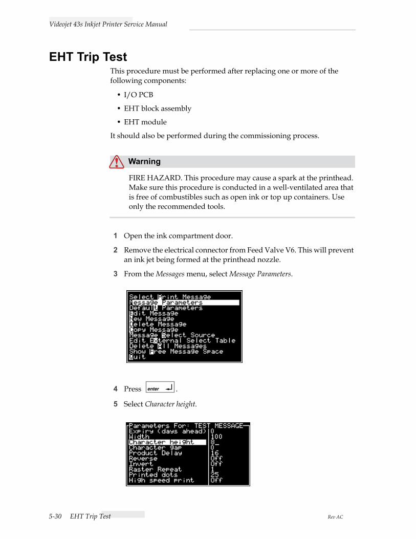
3 From the Messages menu, select Message Parameters.
4 Press .
5 Select Character height.
enter

Videojet 43s Inkjet Printer Service Manual
Rev AC Print Height Test 5-31
6 Set the Character height to 10 then press .
7 To prevent the machine from shutting down, set the charge/gutter detect to DISABLE as instructed in “Gutter Fault and Charge Error Disable” on page 5-6.
8 Fit the modified EHT printhead cover (this cover is included in the Service Tool Kit described in “Service tool kit” on page 13-1).
9 Perform a Quick start from the system menu.
10 Insert the EHT Trip Tool (this item is also included in the Service Tool Kit) between the +ve deflection plate and the 0V plate. The point of the tool should be towards the +ve plate (lower).
11 Ensure that the machine shuts down with an EHT trip indicated on the LCD.
12 Refit the electrical connector to Valve V6.
13 Close the compartment door.
Print Height TestTake two print samples with the printhead between 14 mm and 24 mm from the substrate. Make sure that the customer’s minimum and maximum print height specifications are met:
• A 5 drop high message should be able to print messages down to a minimum height of 2 mm.
• A 24 drop high message should be able to print messages up to a maximum height of 9 mm.
enter

Videojet 43s Inkjet Printer Service Manual
5-32 Backup Calibration Parameters Rev AC
Backup Calibration ParametersOnce you complete printer configuration, it is recommended that you backup the calibration parameters as a “known good” configuration. To backup the current calibration data:
1 From the Configure menu select Backup System Settings.
2 Press to backup the settings.
Restore Calibration ParametersIf at any time, the printer begins to print poorly, you can use this option to restore a “known good” configuration saved previously. Follow these steps to restore saved calibration parameters:
1 From the Configure menu select Restore System Settings.
2 Press to restore the settings.
enter
enter

Videojet 43s Inkjet Printer Service Manual
Rev AC Enable Gutter Detect and Charge Check 5-33
Enable Gutter Detect and Charge Check1 From the System menu select Charge Error Shutdown Disable.
2 Press .
3 Select Charge error and toggle to Enable.
4 Select Gutter fault and toggle to Enable.
5 Press to enable both functions.
enter
enter

Videojet 43s Inkjet Printer Service Manual
5-34 Enable Gutter Detect and Charge Check Rev AC

Rev AC 6-1
6Technical Description
This section describes the main components and interconnections. It includes the following tables, which detail connector pin outs:
• Table 6-1 CON CPU CON_K Keypad Connector
• Table 6-2 CPU CON_232 RS232 Serial Interface
• Table 6-3 CPU CON_B I/O Board Interface
• Table 6-4 CPU CON_S RID Synchronous Port
• Table 6-5 CPU CON_P Power Input Connector
• Table 6-6 CPU CON_D Charge Data To I/O
• Table 6-7 CPU CON_L LCD Interface
• Table 6-8 CPU CON_LAN Serial Port
• Table 6-9 I/O Connector PEC1
• Table 6-10 I/O Connector PEC2
• Table 6-11 I/O Connector SENC
• Table 6-12 I/O Connector LEDS
• Table 6-13 I/O Connector T/LIGHT
• Table 6-14 I/O Connector LEVELS
• Table 6-15 I/O Connector CON_B1
• Table 6-16 I/O Connector CON_EX
• Table 6-17 I/O Connector PIGS
• Table 6-18 I/O Connector VALVES
• Table 6-19 I/O Connector CON_BM2
• Table 6-20 I/O Connector CON_BM2
• Table 6-21 I/O Connector P/TRANS
• Table 6-22 I/O Connector HEAD_2
• Table 6-23 I/O Connector CON_BM1
• Table 6-24 I/O Connector HEAD_1
• Table 6-25 I/O Connector CON_P0

Videojet 43s Inkjet Printer Service Manual
6-2 Main Assemblies Rev AC
• Table 6-26 I/O Connector POWER
• Table 6-27 I/O Connector CH/MOD
• Table 6-28 I/O Connector EHT/FAN
• Table 6-29 I/O Connector FAN_FAIL
• Table 6-30 I/O Connector CON_D
• Table 6-31 I/O Connector B/LIGHT
• Table 6-32 I/O Board Jumper
• Table 6-33 I/O Board Test Points and LEDs
• Table 6-34 PSU Board General Specification
• Table 6-35 PSU Board Output Specifications
Main AssembliesThe printer comprises four main assemblies:
• Cabinet
• Printhead
• Electronics system
• Ink system
Videojet 43s Inkjet Printer Service Manual
Rev AC Cabinet 6-3
Cabinet
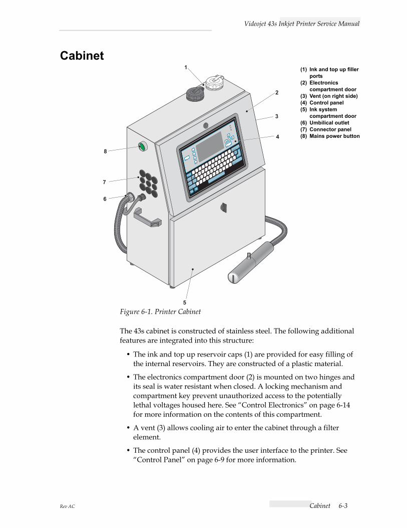
Figure 6-1. Printer Cabinet
The 43s cabinet is constructed of stainless steel. The following additional features are integrated into this structure:
• The ink and top up reservoir caps (1) are provided for easy filling of the internal reservoirs. They are constructed of a plastic material.
• The electronics compartment door (2) is mounted on two hinges and its seal is water resistant when closed. A locking mechanism and compartment key prevent unauthorized access to the potentially lethal voltages housed here. See “Control Electronics” on page 6-14 for more information on the contents of this compartment.
• A vent (3) allows cooling air to enter the cabinet through a filter element.
• The control panel (4) provides the user interface to the printer. See “Control Panel” on page 6-9 for more information.
(1) Ink and top up filler ports
(2) Electronics compartment door
(3) Vent (on right side)(4) Control panel(5) Ink system
compartment door(6) Umbilical outlet(7) Connector panel(8) Mains power button

Videojet 43s Inkjet Printer Service Manual
6-4 Cabinet Rev AC
• The ink system compartment door (5) is mounted on two hinges and its seal is water resistant when closed. See “Ink System” on page 6-43 for more information on the contents of this compartment.
• The umbilical that connects the printer cabinet to the printhead is attached to the cabinet via a threaded fitting, secured with appropriate nuts and washers.
• The connector panel provides inputs for several types of external devices. See “Connector Panel” on page 6-11 for more information.

Videojet 43s Inkjet Printer Service Manual
Rev AC Printhead 6-5
Printhead
Figure 6-2. Printhead
ConstructionThe printhead consists of a chassis on which are mounted the following components:
• The nozzle assembly (4) which forms the ink into a stream of droplets as described below:
The jet valve (17) delivers ink from the ink system to the nozzle assembly.
The bleed valve (18) mounted on the heater module block is normally closed, only opening during purging, flushing of the nozzle and start up and shutdown.
The bleed valve when energized removes air from the feed and return pipework and the nozzle when being purged.
A vacuum is also applied through the bleed valve to the nozzle during a nozzle flush.
1 3
3
2
2
9
11
14
15
16
13
13
10
8
7
6 4
12
5
17
18
(1) Ground potential deflector electrode(2) Phase detector(3) Charge electrode(4) Nozzle assembly(5) Cover switch(6) Knurled screw(7) Rear cover (13) LED(8) Head manifold (14) High voltage deflector electrode(9) Umbilical (15) Gutter(10) Gutter detect (16) Front cover(11) Ceramic transducer (17) Jet valve(12) Nozzle jet orifice (18) Bleed valve

Videojet 43s Inkjet Printer Service Manual
6-6 Printhead Rev AC
The ceramic transducer (11) is fed with a modulation signal. The transducer causes the nozzle assembly to vibrate along its length so that the ink stream from the nozzle jet orifice is formed into individual droplets.
The nozzle jet orifice (12) has a diameter of 60 microns.
• The Light Emitting Diode (LED) (13) is located behind the charge electrode (3). The LED is strobed at the modulation frequency so that the position of individual droplets can be observed with a magnifying glass (x10 minimum). The charge electrode applies an electrical charge to each individual ink droplet. The charge applied to the droplet is variable and affects the position of the droplet on the substrate.
• The phase detector (2) senses the strength of the electrical charge applied to the ink droplets and adjusts the charge pulse timing accordingly.
• The ground potential deflector electrode (1) and the high voltage deflector electrode (14) are parallel rectangular plates. The deflector electrodes generate a constant electrostatic field through which the electrically charged ink droplets pass. The charged ink droplets are deflected by the electrodes, the amount of deflection is dependent on the charge applied to the ink droplet.
• The gutter (15) is the return path for ink droplets which are not used for printing. The gutter delivers the ink back to the ink system.
• The front cover (16) is secured to the printhead by a knurled screw (6). The front cover protects the printhead components. Removal of the cover is sensed by the printer via the cover switch (5). When the cover is removed the voltage to the deflector electrodes is turned off.
• The rear cover (7) protects the printhead internal electrical wiring and ink system tubing.
• The umbilical (9) contains the electrical wiring and ink system tubing from the printer.
• The head heater (8) maintains the temperature of the ink; it consists of a heating element and a temperature sensor.
• The jet valve (17) is mounted on the heater module block. The valve is open whilst printing and closed during the flushing cycle.
• The gutter detect (10) senses when ink is present in the gutter. It’s ink feed tubes are metallic and a signal is fed to one of them. A signal return lead is connected to the other. When ink (which is conductive) is present, the signal passes through it to the return lead. The gutter detect signal is then fed, via the umbilical, to the I/O board in the electronics system.

Videojet 43s Inkjet Printer Service Manual
Rev AC Printhead 6-7
Wiring diagrams for the printhead electrical and ink systems are shown in Figure 6-3 and Figure 6-4.
Figure 6-3. Printhead Electrics and Ink System Wiring Diagram

Videojet 43s Inkjet Printer Service Manual
6-8 Printhead Rev AC
Figure 6-4. Wire routing under printhead manifold block

Videojet 43s Inkjet Printer Service Manual
Rev AC Electronics System 6-9
Electronics SystemThe printer electronics system comprises the following:
• Control panel.
• Connector panel.
• Control electronics.
• Electronics modules.
Control Panel
Figure 6-5. Control Panel
The control panel consists of the following:
• A 70 key industrial grade membrane keypad (5). The keypad is self-adhesive for ease of mounting and is fixed to the electronics compartment door.
• A 240 x 128 pixel backlit Liquid Crystal Display (LCD) (2). The display has a viewing area of 120 mm x 64 mm. The display is mounted on
(1) Function keys (4) Status LEDs(2) Liquid Crystal Display (LCD) (5) Keypad(3) Arrow keys

Videojet 43s Inkjet Printer Service Manual
6-10 Electronics System Rev AC
four insulated studs, which in turn are mounted on the back of the electronics compartment door.
• Basic printer control is provided by four function keys (1) to the left of the LCD screen:
Clean start or stop the ink jet.
Select a message for printing.
Access the menu screen.
Display key status and character set(s) selected for the keypad.
• The arrow keys (3) to the right of the display allow you to navigate through the software menu system.
• The light emitting diodes (4) on the top right of the display indicate the system status as follows;
LAMP(S) ILLUMINATED SYSTEM STATUS
RED The printer cannot print due to a fault or other condition which prevents printing.
AMBER and GREEN The printer requires user intervention to pre-vent a system fault occurring, e.g. ink or top-up low.
GREEN The printer is able to print correctly.
f1
f2
f3
f4

Videojet 43s Inkjet Printer Service Manual
Rev AC Electronics System 6-11
Connector Panel
Figure 6-6. Connector Panel
The connector panel is fitted with the components listed below.
• A mains inlet connector (5) and main power button (1).
• A 3 way DIN connector (6) for print trigger 1.
• A 4 way DIN connector (4) for a shaft encoder.
• A 5 way DIN connector (3) for an RS-232 serial communications link. RS-232 can only be used over relatively short distances (15 meters maximum).
• A 6-way DIN connector (2) for a set of status traffic lights (optional).
(1) Main Power Button (2) Status O/P connector (option)(3) COMM1 Connector(4) Shaft encoder connector(5) Mains inlet connector(6) Print trigger 1 connector

Videojet 43s Inkjet Printer Service Manual
6-12 Electronics System Rev AC
Print Trigger 1 ConnectorThe printer provides a 12V 200mA DC total output for use by a photoelectric Cell (PEC), inductive proximity detector or micro switch. The pin allocation of the print trigger 1 connector (Item 6 in Figure 6-6) is as follows:
Shaft Encoder ConnectorThe printer provides a 12 V (200 mA DC total) output for use by a shaft encoder with a maximum frequency of 100 kHz. The pin allocation of the shaft encoder connector (Item 4 in Figure 6-6) is as follows:
Note:The shaft encoder output must of the PUSH/PULL type.
COMM 1 ConnectorThe printer has an RS-232 communication port linked to the COMM1 connector (Item 3 in Figure 6-6) the pin allocation is as follows:
Pin Function
DIN Pin 1 +12V DC supply to sensor.
DIN Pin 2 Sensor output.
DIN Pin 3 0V DC common.
Pin Function
DIN Pin 1 +12 V DC supply to shaft encoder.
DIN Pin 2 Shaft encoder output “A."
DIN Pin 3 Shaft encoder output "B."
Din Pin 4 0V DC common.
Pin Function
DIN Pin 1 0VDC common.
DIN Pin 2 Transmit data out from the printer.
DIN Pin 3 Received data into the printer.
Din Pin 4 DTR output from the printer.
Din Pin 5 DCD input to the printer.

Videojet 43s Inkjet Printer Service Manual
Rev AC Electronics System 6-13
Status O/P ConnectorThe printer provides an output for a set of status traffic lights via the STATUS O/P connector. The pin allocation of the connector (Item 2 in Figure 6-6) is as follows:
Pin Function
Din Pin 1 Red lamp negative supply.
Din Pin 2 Amber lamp negative supply.
DIN Pin 3 Green lamp negative supply.
Din Pin 4 +24V DC supply to the strobe/siren.
Din Pin 5 Strobe/siren negative supply.
DIN Pin 6 +24V DC common to the traffic lights.

Videojet 43s Inkjet Printer Service Manual
6-14 Control Electronics Rev AC
Control Electronics
General
Figure 6-7. Control Electronics
The control electronics in 43s printers are based on a common Central Processing Unit (CPU) board (2), and an INPUT/OUTPUT (I/O) board (3).
For the 43s printer to operate as designed, it has three other electronic component parts. These are the modular power supply (PSU) (1), the Liquid Crystal Display (LCD) and the integral keypad. The PSU connects directly to the I/O board, but the LCD and KEYPAD connect directly to the CPU. Note that the LCD backlight inverter connects to the I/O board.
The printer can be interrogated over a serial link in order to assess performance. This serial link can be a direct RS-232 connection to a local personal computer or via a MODEM and the telephone network.
(1) PSU module(2) CPU board(3) I/O board(4) Ink pump motor driver
board

Videojet 43s Inkjet Printer Service Manual
Rev AC Control Electronics 6-15
CPU BoardThe CPU Board circuit diagram is included in Appendix A of this manual.
Figure 6-8. CPU Board Major Components
Major ComponentsThe CPU board (Item 1 in Figure 6-8) contains the hardware and software for system control. It comprises the following major components:
• The CPU board (1) is a multi-layered motherboard that monitors and controls all of the major printer functions. The board interfaces with the I/O board, PSU module, expansion board (if fitted) and external devices (if connected) to provide an integrated product coding system.
• Integrated Circuit (IC) U31 (2) produces keyboard drive signals to determine which key has been pressed.
(1) CPU board(2) IC U31(3) IC U40 and U41(4) IC U38 and U39
(5) IC U19(6) IC U9(7) IC U21(8) Ni-MH battery

Videojet 43s Inkjet Printer Service Manual
6-16 Control Electronics Rev AC
• IC U40 and IC U41 (3) are flash memory devices and are programmed by Videojet to hold the following information:
application softwareprinter default setup
Note: These chips are the only difference between a 43s CPU board and a 46s CPU board.
• IC U38 and IC U39 (4) are two integrated circuit Random Access Memory (RAM) devices that contain the printer configuration, calibration and message storage memory. To avoid loss of data when the printer is switched off they are backed up by a Nickel Metal Hydride (Ni-MH) battery.
• IC U19 (5) is the microprocessor that monitors incoming data from the I/O ports and translates software commands into machine statements that control the electronic system and ink system to produce a printed message.
• IC U21 (7) is a Real Time Clock (RTC) which contains a clock/calendar. It has a battery backup so that the current time and date do not have to be manually set each time the printer is switched on.
• The Ni-MH battery (8) supplies the voltage necessary to retain Real Time Clock (RTC) and RAM data when the printer is switched OFF. The battery is automatically charged when the printer is switched ON.
• IC U9 (6) is a Dual Universal Asynchronous Receive Transmit (DUART) which can be configured to interface with different devices to transmit and receive data.

Videojet 43s Inkjet Printer Service Manual
Rev AC Control Electronics 6-17
ConnectorsThe CPU board connectors shown in Figure 6-9. Pinout details are given in the tables that follow.
Figure 6-9. CPU Board Connectors
(1) CON_K (Keypad connector)(2) CON_232(3) CON_B (Interboard connector)(4) CON_S
(5) CON_P (Interboard connector)(6) CON_D (Interboard connector)(7) CON_L (LCD connector)(8) CON_LAN

Videojet 43s Inkjet Printer Service Manual
6-18 Control Electronics Rev AC
CON_K (Item 1 in Figure 6-9) is connected to the keypad
Pin Signal Function Pin Signal Function
1 GND EMC earth connection
12 SL1 Scan line 1
2 ALT ALT key 13 SL2 Scan line 2
3 CTL Control key 14 SL3 Scan line 3
4 SFT Shift key 15 SL4 Scan line 4
5 0V Scan line 7 16 SL5 Scan line 5
6 SL7 Return line 0 17 SL6 Scan line 6
7 RL0 18 RL4 Return line 4
8 RL1 Return line 1 19 RL5 Return line 5
9 RL2 Return line 2 20 RL6 Return line 6
10 RL3 Return line 3 21 RL7 Return line 7
11 SL0 Scan line 0 22 GND EMC earth connection
Table 6-1: CON CPU CON_K Keypad Connector
CON_232 (2) is a RS232 serial communications port (COM1) and can be con-nected to any other device which supports RS232.
Pin Signal Function Pin Signal Function
1 TXDA Transmit data 4 DCD Data carrier detect
2 DTR Data terminal ready
5 COM Common
3 RXDA Receive data 6 - +8V
Table 6-2: CPU CON_232 RS232 Serial Interface

Videojet 43s Inkjet Printer Service Manual
Rev AC Control Electronics 6-19
CON_B (3) is an interboard connector which connects the CPU board to the I/O board.
Pin Signal Function Pin Signal Function
1 0 V Common 11 opto I/O Expansion board enable
2 Sel2 Not used 12 adc A/D converter output enable
3 ex1 Photocell 1 input 13-20 cb0 to cb7 Control bus bits 0 to 7
4 ex2 Phase detector 21-28 db0 to db7 Data bus bits 0 to 7
5 ex3 A-D end of conversion 29 qddc D/A converter output enable
6 ex4 Phase detector 30 levels Optical level sensors select
7 ex5 Photocell 2/shaft encoder quadrature input
31 I/O PPI enable
8 sel3 Print/phase 32 sft-enc Shaft encoder input
9 strobe LED strobe 33 extra1 Traffic light enable
10 PWM Pump control (pulse width modulation)
34 contrast LCD contrast voltage
Table 6-3: Table 5 CPU CON_B I/O Board Interface
CON_S (4) is a high speed synchronous port
Pin Signal Function Pin Signal Function
1 TXD Asynchronous transmit output 5 SDATA Synchronous data
2 RXD Asynchronous receive input 6 SDEN0 Synchronous enable 0
3 0 V Asynchronous data common 7 SDEN1 Synchronous enable 1
4 SCLK Synchronous clock 8 0 V Synchronous common
Table 6-4: CPU CON_S RID Synchronous Port

Videojet 43s Inkjet Printer Service Manual
6-20 Control Electronics Rev AC
CON_P (5) is an interboard connector which connects the CPU board to the I/O board.
Pin Signal Function Pin No. Signal Function
1 to 4 0 V Common in out from PSU (via I/O)
11 and 12 - 15 V - 15 V input from PSU (via I/O)
5 to 8 +5 V +5 V input from PSU (via I/O)
13 and 14 GND via I/O
9 and 10
+15 V +15 V input from PSU (via I/O)
Table 6-5: CPU CON_P Power Input Connector
CON_D (6) is an interboard connector which connects the CPU board to the I/O board.
Pin Signal Function
1 to 8 00 - 07 Droplet charge data
9 and 10 0 V Common
11 to 20 - Not used at present
Table 6-6: CPU CON_D Charge Data To I/O
CON_L (7) is connected to the LCD.
Pin Signal Function Pin Signal Function
1 GND Ground 8 Ia1 Control bus bit 7
2 0 V 9 - Not connected
3 VCC +5 V 10 RESET LCD controller reset
4 CONTRAST LCD contrast 11 to 18
ad0 to ad7
Data lines
5 WR Write 19 0 V Font Select
6 RD Read 20 sel5 Select inverse video
7 lcd ce LCD chip enable
Table 6-7: CPU CON_L LCD Interface
Videojet 43s Inkjet Printer Service Manual
Rev AC Control Electronics 6-21
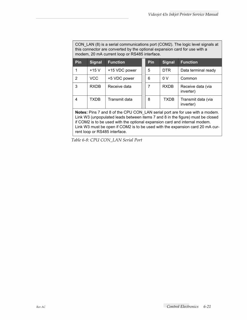
CON_LAN (8) is a serial communications port (COM2). The logic level signals at this connector are converted by the optional expansion card for use with a modem, 20 mA current loop or RS485 interface.
Pin Signal Function Pin Signal Function
1 +15 V +15 VDC power 5 DTR Data terminal ready
2 VCC +5 VDC power 6 0 V Common
3 RXDB Receive data 7 RXDB Receive data (via inverter)
4 TXDB Transmit data 8 TXDB Transmit data (via inverter)
Notes: Pins 7 and 8 of the CPU CON_LAN serial port are for use with a modem.Link W3 (unpopulated leads between items 7 and 8 in the figure) must be closed if COM2 is to be used with the optional expansion card and internal modem.Link W3 must be open if COM2 is to be used with the expansion card 20 mA cur-rent loop or RS485 interface.
Table 6-8: CPU CON_LAN Serial Port

Videojet 43s Inkjet Printer Service Manual
6-22 Control Electronics Rev AC
I/O BoardThe I/O board Item 1 in Figure 6-10 is mounted over the CPU board and interfaces the printer to the following:
• the ink system;
• product sensors;
• external devices.
The I/O board is connected to the CPU board via interboard connectors CON_B1, CON_D and CON_P0. The I/O Board Circuit Diagram is included Appendix A in this manual.
Major Components
Figure 6-10. I/O Board Major Components
• IC U20 (2) is a Quadruple Digital to Analogue Converter (QDAC) which converts digital inputs into analogue 0 to +5 volt signals to control functions on the I/O board.
(1) I/O board(2) IC U20(3) Ink Pump motor driver board(4) IC U1(5) VR1(6) 285 V DC power supply(7) IC U15(8) IC U16

Videojet 43s Inkjet Printer Service Manual
Rev AC Control Electronics 6-23
• The ink pump motor drive board (3) acts as an interface between the I/O board and the ink system pump motor, it is connected to the I/O board via connectors CON_BM1 and CON_BM2. IC U1 (4) acts as the ink pump motor controller. A circuit diagram of the board is supplied in Appendix A of this manual.
• The 300 VDC power supply (6) provides the voltage supply to the charge amplifier which is used to charge the ink droplets.
• IC U15 (7) is a Programmable Peripheral Interface (PPI) which is used to read the states of various sensors and control functions and to switch control valves and some supervisory lines.
• IC U16 (8) is an Analogue to Digital Converter (ADC) which is used to convert analogue inputs from the ink system into an 8 bit value for ink system control.

Videojet 43s Inkjet Printer Service Manual
6-24 Control Electronics Rev AC
Connectors
Figure 6-11. I/O Board Connectors
PEC1 (1) - Product sensor 1 via the connector panel.
Pin No. Signal Function
1 +V0 Positive DC supply to sensor
2 EXT PEC 1/2 Input from sensor
3 0 V Common
Table 6-9: I/O Connector PEC1
(1) PEC1(2) PEC2(3) SENC(4) LEDS(5) T/LIGHT(6) LEVELS(7) CON_B1(8) CON_EX
(9) PIGS(10) VALVES(11) CON_BM2(12) PUMP(13) P/TRANS(14) HEAD_2(15) CON_BM1(16) HEAD_1
(17) POWER(18) CON_P0(19) CH/MOD(20) EHT/FAN(21) FAN_FAIL(22) CON_D(23) JB1(24) B/LIGHT

Videojet 43s Inkjet Printer Service Manual
Rev AC Control Electronics 6-25
Caution
EQUIPMENT DAMAGE. The I/O Board LEDS connector must not be used to drive anything other than LEDs as specified otherwise damage may occur.
PEC2 (2) - Product sensor 2 via the connector panel.
Pin No. Signal Function
1 +V0 Positive DC supply to sensor
2 EXT PEC 1/2 Input from sensor
3 0 V Common
Table 6-10: I/O Connector PEC2
SENC (3) - Shaft encoder via the connector panel.
Pin No. Signal Function
1 +V0 Positive DC supply to shaft encoder
2 SHAFT ENCODER A Input A from shaft encoder
3 SHAFT ENCODER B Input B from shaft encoder
4 0 V Common
Table 6-11: I/O Connector SENC
LEDS (4) - LEDs are fitted on the front panel to mimic traffic lights.
Pin Signal Function Pin Signal Function
1 Red + Red LED anode (+)
5 Red - Red LED cathode (-)
2 Yellow + Yellow LED anode (+)
6 Yellow - Yellow LED cathode (-)
3 Green + Green LED anode (+)
7 Green - Green LED cathode (-)
4 Strobe + Strobe LED anode (+)
8 Strobe - Strobe LED cathode (-)
Table 6-12: I/O Connector LEDS

Videojet 43s Inkjet Printer Service Manual
6-26 Control Electronics Rev AC
T/LIGHT (5) - Status traffic lights via the connector panel.
Pin Signal Function Pin Signal Function
1 +24 V +24 V DC to all lights 4 0 V GREEN Negative supply for green lamp
2 0 V RED Negative supply for red lamp
5 +24 V +24 V DC to strobe/siren
3 0 V AMBER Negative supply for amber lamp
6 0 V STROBE Negative supply for strobe
Table 6-13: I/O Connector T/LIGHT

Videojet 43s Inkjet Printer Service Manual
Rev AC Control Electronics 6-27
LEVELS (6) - Ink system level sensors.
Pin Signal Function Pin Signal Function
1 +5 V +5 V, Mixer low sensor LED anode
18 +5 V +5 V, VMS high sensor photo transistor collector
2 +5 V +5 V, Mixer low sensor photo transistor collector
19 0 V 0 V, VMS high sensor LED cathode
3 0 V 0 V, Mixer low sensor LED cathode
20 lev5 VMS high sensor output
4 lev1 Mixer low sensor output 21 +5 V +5 V, Ink res. low sensor LED anode
5 +5 V +5 V, Mixer OK sensor LED anode
22 +5 V +5 V Ink res. low sensor photo transistor collector
6 +5 V +5 V, Mixer OK sensor photo transistor collector
23 0 V 0 V, Ink res. low sensor LED cathode
7 0 V 0 V, Mixer OK sensor LED cathode
24 lev6 Ink res. low sensor output
8 lev 2 Mixer OK sensor output 25 +5 V +5 V, Solvent res. low sensor LED anode
9 +5 V +5 V, Mixer high sensor LED anode
26 +5 V +5 V, solvent res. low sensor photo transistor collector
10 +5 V +5 V, Mixer high sensor photo transistor collector
27 0 V 0 V, Solvent res. low sensor LED cathode
11 0 V 0 V, Mixer high sensor LED cathode
28 lev7 Solvent res. low sensor out-put
12 lev3 Mixer high sensor output 29 +15 V
13 +5 V +5 V, VMS low sensor LED anode
30 0 V
14 +5 V +5 V, VMS low sensor photo transistor collector
31 - 15 V
15 0 V 0 V, VMS low sensor LED cathode
32 0 V
16 lev4 VMS low sensor output 33 GND
17 +5 V +5 V, VMS high sensor LED anode
34 GND
Table 6-14: I/O Connector LEVELS

Videojet 43s Inkjet Printer Service Manual
6-28 Control Electronics Rev AC
CON_B1 (7) - Interboard connector to I/O board to the CPU board.
Pin Signal Function Pin Signal Function
1 0 V 11 opto I/O E
2 - Not used 12 adc A/D converter output enable
3 pec1 Photocell 1 output 13 to 20 cb0 to cb7 Control bus bits 0 to 7
4 phase det
Phase detector 21 to 28 db0 to db7 Data bus bits 0 to 7
5 ADEOC
A-D end of conversion 29 qddc D/A converter output enable
6 phase det
Phase detector 30 levels Optical level sensors enable
7 pec2 Photocell 2/shaft encoder quadrature output
31 pcs3 PPI enable
8 print/phase
Print/phase 32 shaft enc Shaft encoder output
9 strobe LED strobe 33 extra 1 Traffic light enable
10 pwm Pump control (pulse width modulation)
34 contrast LCD contrast
Table 6-15: Table 17 I/O Connector CON_B1
CON_EX (8) - Interboard connector to I/O board to the optional expansion board.
Pin Signal Function Pin Signal Function
1 VCC +5 V DC 15 TACHO For use with external DC tacho
2 to 9 db0 to db7 Data bus bits 0 to 7 16 0 V
10 External message select 17 0 V
11 Opto-isolated output select 18 +24 V
12 cb6 Control bus bit 6 (not used) 19 - 24 V
13 cb7 Control bus bit 7 (not used) 20 GND
14 cb0 Control bus bit 0 (not used)
Table 6-16: I/O Connector CON_EX
Videojet 43s Inkjet Printer Service Manual
Rev AC Control Electronics 6-29
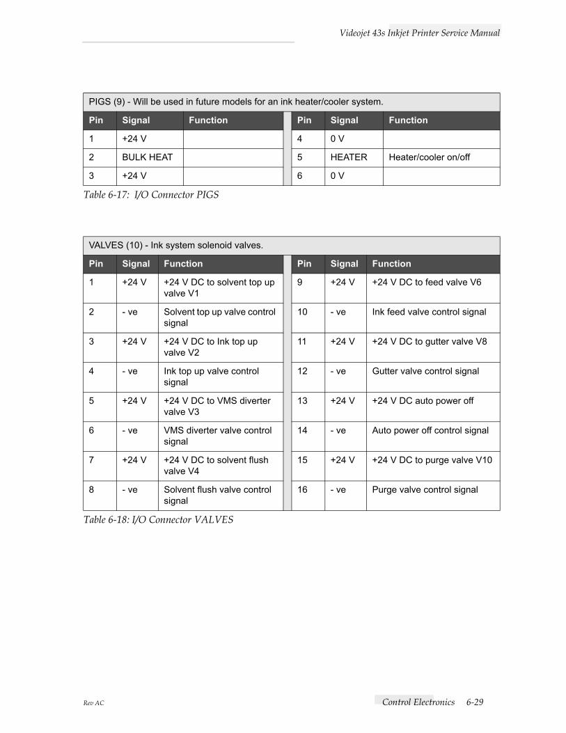
PIGS (9) - Will be used in future models for an ink heater/cooler system.
Pin Signal Function Pin Signal Function
1 +24 V 4 0 V
2 BULK HEAT 5 HEATER Heater/cooler on/off
3 +24 V 6 0 V
Table 6-17: I/O Connector PIGS
VALVES (10) - Ink system solenoid valves.
Pin Signal Function Pin Signal Function
1 +24 V +24 V DC to solvent top up valve V1
9 +24 V +24 V DC to feed valve V6
2 - ve Solvent top up valve control signal
10 - ve Ink feed valve control signal
3 +24 V +24 V DC to Ink top up valve V2
11 +24 V +24 V DC to gutter valve V8
4 - ve Ink top up valve control signal
12 - ve Gutter valve control signal
5 +24 V +24 V DC to VMS diverter valve V3
13 +24 V +24 V DC auto power off
6 - ve VMS diverter valve control signal
14 - ve Auto power off control signal
7 +24 V +24 V DC to solvent flush valve V4
15 +24 V +24 V DC to purge valve V10
8 - ve Solvent flush valve control signal
16 - ve Purge valve control signal
Table 6-18: I/O Connector VALVES

Videojet 43s Inkjet Printer Service Manual
6-30 Control Electronics Rev AC
CON_BM2 (11) - Ink pump motor driver board.
Pin Signal Function Pin Signal Function
1 B OUT Stator drive B (green) 5 HC Position signal from Hall effect sensor C (green)
2 A OUT Stator drive A (black) 6 0 V Hall effect sensor -ve supply
3 C OUT Stator drive C (white) 7 HB Position signal from Hall effect sensor B (white)
4 +6 V Hall effect sensor +ve supply
8 HA Position signal from Hall effect sensor A (blue)
Table 6-19: I/O Connector CON_BM2
PUMP (12) - Ink system pump.
Pin Signal Function Pin Signal Function
1 B OUT Stator drive B 5 HC Position signal from Hall effect sensor C
2 A OUT Stator drive A 6 0 V Hall effect sensor -ve supply
3 C OUT Stator drive C 7 HB Position signal from Hall effect sensor B
4 +6 V Hall effect sen-sor +ve supply
8 HA Position signal from Hall effect sensor A
Table 6-20: I/O Connector CON_BM2
P/TRANS (13) - Ink system temperature sensor and the pressure transducer.
Pin Signal Function Pin Signal Function
1 +10 V +10 V DC supply volt-age to transducer
5 BULK INK TEM-PERATURE
Output from mixer tank temperature sensor
2 +ve +ve output from transducer
6 0 V 0 V to temperature sen-sor
3 - ve - ve output from transducer
7 +5 V +5 V DC to temperature sensor
4 0 V 0 V to transducer 8 GND
Table 6-21: I/O Connector P/TRANS

Videojet 43s Inkjet Printer Service Manual
Rev AC Control Electronics 6-31
HEAD_2 (14) - Printhead connector 2 via the umbilical
Pin Signal Function Pin Signal Function
1 VCC +5 V DC 7 0 V
2 Not used 8 +5 V +5 V DC to temp sensor
3 Not used 9 HE temp Head temp sensor output
4 0 V 10 0 V 0 V to temp sensor
5 VCC +5 V DC 11 Head heater return
6 Fire sensor Fire sensor (not used at present)
12 +24 V +24 V to head heater
Table 6-22: I/O Connector HEAD_2
CON_BM1 (15) - Ink pump motor driver board.
Pin Signal Function Pin Signal Function
1 +24 V Supplies to motor control board
5 ENABLE Enable ink pump motor
2 0 V 6 PRESS TRANS I/P Pressure transducer input
3 +15 V 7 REQ PRESS I/P Requested pressure input
4 - 15 V 8 GND
Table 6-23: I/O Connector CON_BM1
HEAD_1 (16) - Printhead connector 1 via the umbilical.
Pin Signal Function Pin Signal Function
1 +12 V +12 V DC to phase detector amplifier
6 0 V 0 V connection to LED cathodes
2 - 12 V - 12 V DC to phase detector amplifier
7 STROBE LED
Strobe signal to LED anode
3 0 V 0 V connection to phase detector amplifier
8 Signal from phase detector amp
4 GUTTER DETECT
Oscillator signal to gutter detect
9 LID SWITCH
+ve to lid switch
5 0 V 0 V connection to gutter detect
10 0 V 0 V connection to lid switch
Table 6-24: I/O Connector HEAD_1

Videojet 43s Inkjet Printer Service Manual
6-32 Control Electronics Rev AC
CON_P0 (17) - Interboard connector from I/O board to CPU board. It carries the DC voltages from the PSU.
Pin Signal Function Pin Signal Function
1 to 4 0 V 0 V 11 and 12 - 15 V - 15 V DC to CPU
5 to 8 +5 V +5 V DC to CPU 13 and 14 GND
9 and 10 +15 V +15 V DC to CPU
Table 6-25: I/O Connector CON_P0
POWER (18) - PSU.
Pin Signal Function Pin Signal Function
1 15 V 15 V DC from PSU 5 +5 V +5 V DC from PSU
2 0 V 0 V from PSU 6 +24 V +24 V DC from PSU
3 +5 V +5 V DC from PSU 7 0 V 0 V from PSU
4 - 15 V - 15 V DC from PSU 8 - 24 V - 24 V DC from I/O board
Table 6-26: I/O Connector POWER
CH/MOD (19) - Printhead via the umbilical.
Pin Signal Function Pin Signal Function
1 CHARGE Charge amplifier output 3 mod 1a Modulation 0 V
2 0 V CHARGE Charge amplifier 0 V 4 mod 1b Modulation signal output
Table 6-27: I/O Connector CH/MOD
Videojet 43s Inkjet Printer Service Manual
Rev AC Control Electronics 6-33
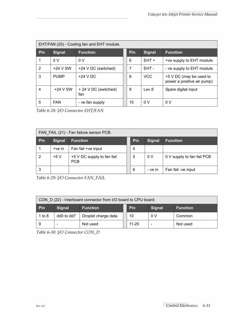
EHT/FAN (20) - Cooling fan and EHT module.
Pin Signal Function Pin Signal Function
1 0 V 0 V 6 EHT + +ve supply to EHT module
2 +24 V SW +24 V DC (switched) 7 EHT - - ve supply to EHT module
3 PUMP +24 V DC 8 VCC +5 V DC (may be used to power a positive air pump)
4 +24 V SW + 24 V DC (switched) fan
9 Lev 8 Spare digital input
5 FAN - ve fan supply 10 0 V 0 V
Table 6-28: I/O Connector EHT/FAN
FAN_FAIL (21) - Fan failure sensor PCB.
Pin Signal Function Pin Signal Function
1 +ve in Fan fail +ve input 4
2 +5 V +5 V DC supply to fan fail PCB
5 0 V 0 V supply to fan fail PCB
3 6 - ve in Fan fail -ve input
Table 6-29: I/O Connector FAN_FAIL
CON_D (22) - Interboard connector from I/O board to CPU board.
Pin Signal Function Pin Signal Function
1 to 8 dd0 to dd7 Droplet charge data 10 0 V Common
9 - Not used 11-20 - Not used
Table 6-30: I/O Connector CON_D

Videojet 43s Inkjet Printer Service Manual
6-34 Control Electronics Rev AC
B/LIGHT (24) - Backlight of the Liquid Crystal Display (LCD)
Pin Signal Function
1 +24 V +24 V DC to backlight inverter
2 - ve BKLT Backlight -ve supply
3 GND
Table 6-31: I/O Connector B/LIGHT
JB1 (23) Used to configure the photocell inputs PEC1 and PEC2.PEC1 is connected to product error 1 via the connector panel.PEC2 is connected to product error 2 via the connector panel.
Table 6-32: I/O Board Jumper
Test point Signal LED Color Function
TP1 (14) 0 V. LED1 (11) green Customer 10 V isolated supply present.
TP2 (8) +285 V DC charge amplifier supply.
LED2 (9) red Charge amplifier supply.
TP3 (12) Ink temperature at viscom-eter delivery line.
LED3 (6) yellow -24 V.
TP4 (7) Charge voltage to print-head.
LED4 (5) red -15 V charge amplifier.
TP5 (13) Ink system pressure (1 V — 1 bar).
LED5 (10) green +24 V valve/fan/heater supply.
TP6 (4) Modulation drive voltage to printhead.
TP7 (2) Phase detector output prior to hedgehog clipping.
TP8 (3) 0 V.
TP9 (1) +5 V (can be used with logic probe).
Table 6-33: I/O Board Test Points and LEDs

Videojet 43s Inkjet Printer Service Manual
Rev AC Control Electronics 6-35
Figure 6-12. I/O Board Test Points and LEDs
(1) TP9(2) TP7(3) TP8(4) TP6
(9) LED2(10) LED5(11) LED1(12) TP3
(5) LED4(6) LED3(7) TP4(8) TP2
(13) TP5(14) TP1
Videojet 43s Inkjet Printer Service Manual
6-36 Control Electronics Rev AC
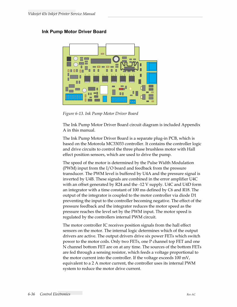
Ink Pump Motor Driver Board
Figure 6-13. Ink Pump Motor Driver Board
The Ink Pump Motor Driver Board circuit diagram is included Appendix A in this manual.
The Ink Pump Motor Driver Board is a separate plug-in PCB, which is based on the Motorola MC33033 controller. It contains the controller logic and drive circuits to control the three phase brushless motor with Hall effect position sensors, which are used to drive the pump.
The speed of the motor is determined by the Pulse Width Modulation (PWM) input from the I/O board and feedback from the pressure transducer. The PWM level is buffered by U4A and the pressure signal is inverted by U4B. These signals are combined in the error amplifier U4C with an offset generated by R24 and the -12 V supply. U4C and U4D form an integrator with a time constant of 100 ms defined by C6 and R18. The output of the integrator is coupled to the motor controller via diode D1 preventing the input to the controller becoming negative. The effect of the pressure feedback and the integrator reduces the motor speed as the pressure reaches the level set by the PWM input. The motor speed is regulated by the controllers internal PWM circuit.
The motor controller IC receives position signals from the hall effect sensors on the motor. The internal logic determines which of the output drivers are active. The output drivers drive six power FETs which switch power to the motor coils. Only two FETs, one P channel top FET and one N channel bottom FET are on at any time. The sources of the bottom FETs are fed through a sensing resistor, which feeds a voltage proportional to the motor current into the controller. If the voltage exceeds 100 mV, equivalent to a 2 A motor current, the controller uses its internal PWM system to reduce the motor drive current.

Videojet 43s Inkjet Printer Service Manual
Rev AC Control Electronics 6-37
The amplifier/integrator U4 power supply is ± 12 V derived from the ± 15 V supplies from the I/O board. And the motor supply is taken from the +24 V supply via an adjustable 3 A regulator set to a nominal 22.5 V. The Hall effect sensors are supplied from the 6.25 V reference supply from the controller IC.
The motor controller PCB has two links fitted to enable the sensors to be either 60 degree or 120 degree types controlling the direction of the motor. The normal configuration of the board has no links fitted.
The controller is also capable of driving a brushed motor by setting the sensor inputs to a fixed configuration and using only two of the motor driver outputs. This can be most easily achieved by wiring the motor connector to the required configuration. It is then possible to use the same motor controller and I/O boards in machines using both brushed and brushless motors without changing the board set up.
Also included on this board is a circuit to oscillate the gutter valve on and off at a pre-selectable frequency of 3 Hz or 6 Hz. Selectable by J4, which can also disable the circuit. The effect of this circuit is to reduce the solvent consumption caused by sucking back excess air. This valve oscillation only occurs when the machine is printing, or is ready to print. i.e. EHT is on, therefore it is inhibited when the EHT is off via J5 and J3 pin 1 going low. When the EHT is on ISO1 shorts out R44 therefore pulling the reference on U7 pin 13 up and enabling a square wave output from the comparator U7d.
The Quad Op-Amp U7 forms an astable oscillator which creates a triangular wave output on pin 8 which is fed into the comparator to generate the square wave output required to switch Q7 on and off. R 40 is used to adjust the mark/space ratio of the signal.
There is also a small circuit designed to prevent the feed valve from overheating if left on for long periods.
The valve requires an electrical signal of 24 V for it to switch on, although once it is switched on it only requires approximately 12 V to remain energized. A hit and drop circuit is used which switches R47 in series with the feed valve 250 ms after retracting, reducing the voltage flowing across it. This is achieved by Q8 becoming turned on when the feed valve is switched on by J2 pin 10 going low. 250 ms later C13 charges up allowing the gate voltage to drop and for Q8 to turn off.
D5 protects the I/O board from damage due to C11 discharging during power down. D2 & D6 are flywheel diodes which reduce the back EMF generated by the gutter valve, and the feed valve, respectively.
The 43s motor control PCB contains additional “hit and hold” circuits to control the “Feed” and “Bleed” pico valves mounted within the printhead. These valves require 24 V for about 50 ms for them to open, after which

Videojet 43s Inkjet Printer Service Manual
6-38 Control Electronics Rev AC
the drive voltage must reduce to 12 V to hold them open without excessive dissipation. This is achieved with the circuit shown in Figure 6-14.
Figure 6-14. Pico Valve Control Circuit
The valve is connected between TO VALVE line and the 24 V SUPPLY line.
When the valve is switched on the IO PCB driver pulls the “CONTROL” line low, which pulls the source of the FET low. The gate is held high by C14, and the FET is turned on, and the drain remains close to the CONTROL rail, thus the valve has 24 V across it.
As R53 charges C14, after approximately 50 ms the gate/source voltage drops to a point where the FET turns off, effectively leaving the valve in series with R54. As this is 280 ohms and the valve is 280 ohms, there is a potential of 12 V across the valve.
When the software turns the valve off, the CONTROL line is made open circuit by the IO PCB driver.
The valves resistance and R54 in series pull the CONTROL line up to 24 V, which discharges C14 via D11.
D9 ensures that the back EMF from the valves inductance does not exceed the FET’s maximum voltage rating.
TP34 D9GF1B
R54280R
R53360k
D11GF1B
Q10BSP17
C14100n
24V SUPPLY
TO VALVE
CONTROL
11
324

Videojet 43s Inkjet Printer Service Manual
Rev AC PSU Board 6-39
PSU Board
General SpecificationThe PSU (Item 1 in Figure 6-7) is a switch mode power supply with the following general specification:
Input voltage 88 VAC to 260 VAC.
Input frequency 47 Hz to 63 Hz.
Inrush current (cold) 15 A at 115 VAC, 30 A at 230 VAC.
Operating temperature 0° to 50° C.
Storage temperature -20° to 85° C.
Cooling Free air convection.
Efficiency 80% typical.
Holdup time 20 ms.
Overvoltage type crowbar, trip point 5.9 V to 7 V.
Overload protection Foldback.
Switching frequency >30 Kilohertz (kHz).
Designed to comply with
UL478, 1012, CSA22.2, VDE0806.
EMI Meets FCC class “B”.
Table 6-34: PSU Board General Specification

Videojet 43s Inkjet Printer Service Manual
6-40 PSU Board Rev AC
Output Specification
Notes:Each output can provide up to a maximum load, but total load cannot exceed 85 W continuously.
+5 V output is adjusted to +/- 1% at 60% rated load at factory.
Tolerance is measured with all outputs at 60% rated load.
Line regulation is measured from low line to high line at rated load.
Load regulation is measured by +/- 40% load change from 60% rated load, and all other outputs is kept at 60% rated load.
Ripple and noise is measured by using a 12" twisted wire terminated with a 47µF capacitor.
Efficiency is measured at rated load.
All parameters except line regulation are specified at 115/230 VAC input, rated load, 25° C ambient.
Output Voltage(V)
Load A Tolerance(+/- %)
Ripple Noise(mV)
Line Reg (%)
Load Reg (%)
Min Rated Max
+5 0.5 4 8 1 50 1 1
+15 0 0.5 1 10 100 2 8
-15 0 0.5 1 10 100 2 8
+24 V 0.1 2 2.5 5 150 1 5
Table 6-35: PSU Board Output Specifications

Videojet 43s Inkjet Printer Service Manual
Rev AC Electronics Modules 6-41
Electronics Modules
Figure 6-15. Printer Electronics Modules
Electronics Compartment Cooling FanThe electronics compartment cooling fan (Item 1 in Figure 6-15) draws filtered air over the electronics system to cool it. The fan is also used to dilute and disperse vapor produced from the ink system. A fan failure card (3) monitors the flow of cooling air in the filter compartment, if the fan fails then the flow of cooling air stops, this is detected by the fan failure card which outputs an alarm signal to the CPU via the I/O board.
(1) Electronics compartment cooling fan
(2) Fan failure card(3) EHT module(4) Ink system pump

Videojet 43s Inkjet Printer Service Manual
6-42 Electronics Modules Rev AC
EHT ModuleThe EHT module (2) generates the extra high tension voltage required by the high voltage deflector electrode.
Ink System PumpThe ink system pump (4) provides the flow of ink to drive the ink system. The motor is a brushless DC type. The pump head is a geared type producing ink flow from two rotating meshed gears.
Mains Input CircuitThe AC mains supply (Figure 6-16) is supplied, via three core cable to the mains filter. The line and neutral lines are fed to the On/Off switch. After the on/off switch the line and neutral lines are fed to TB1 connector on the PSU. The mains fuse is located in the PSU (See “PSU Module Fuse Replacement” on page 8-8 for more information). This fuse is rated T3A 110-240V.
Figure 6-16. Mains Input Circuit

Videojet 43s Inkjet Printer Service Manual
Rev AC Ink System 6-43
Ink System
GeneralThe ink system provides a continuous supply of ink to the printhead at the correct pressure and at the correct temperature/viscosity combination. The ink system is housed in the printer cabinet and the components are interconnected by PTFE tubing. Figure 6-18. on page 6-44 shows the ink system components.
Solenoid ValvesThe flow of ink in the ink system is controlled by eight solenoid operated spool valves. Except for valves V11 and V12, the valves (see Figure 6-17) are all of the same design. The valves are single-acting, operated by an electrical actuator (solenoid) with spring return. The flow is from the common port “C” (3) to the normally open port “R” (1) when the valve is not energized (off). When energized (on) the flow is from the common port to the normally closed port “P” (2). Valves V11 and V12 are miniature shut-off valves and are mounted on the heater block within the printhead.
Figure 6-17. Solenoid Valve
2-port valves have a blanking plug welded over the “R” port. 3-port valves have a barb fitted at the “R” port.
V1 Solvent Top-up Valve (located at the solvent top-up reservoir)When V1 (Item 4 in Figure 6-18) is energized, solvent top-up is drawn through the valve under vacuum from the venturi.
V1 is pulsed for 1 second intervals when the VMS system detects that the ink viscosity is at least 1 second too thick.
(1) Normally open port (R)(2) Normally closed port (P)(3) Common port (C)

Videojet 43s Inkjet Printer Service Manual
6-44 Ink System Rev AC
V1 is a 2-port valve
Figure 6-18. Ink System Components
(1) Top up reservoir manifold(2) Ink reservoir manifold(3) Ink system pump(4) Solenoid valve V1 (Top Up Addition valve)(5) Solenoid valve V2 (Ink Addition valve)(6) Top up reservoir(7) Ink reservoir(8) Flush pump(9) Pre pump filter
(10) Pressure transducer housing(11) Main filter(12) Mixer tank(13) Solenoid valve V6 (Ink)(14) Solenoid valve V8 (Gutter)(15) Solenoid valve V3 (VMS)(16) Solenoid valve V7 (Flush pump)(17) FMS

Videojet 43s Inkjet Printer Service Manual
Rev AC Ink System 6-45
V2 Ink Top-up Valve (located at the ink reservoir)When V2 (5) is energized, replenishment ink is drawn through the valve under vacuum from the venturi.
V2 is energized when the level of the ink in the FMS mixer tank falls below the “Mixer tank OK” ink level detector.
V2 is a 2-port valve.
V3 VMS Diverter Valve (located on the FMS ink system)The VMS diverter valve (15) controls the flow of ink into the VMS chamber via restrictor (R1), which controls the ink viscosity.
V3 is energized when the VMS system becomes operational under software control or when the ink level falls below the VMS “low level detect” probe.
V3 is de-energized after a short time delay once ink is detected by the VMS “high level” detect probe.
The time taken for ink to flow out of the VMS chamber through a restrictor orifice between the high and low level detect probes determines the ink viscosity.
When V3 is de-energized, the flow of ink is directed into FMS mixer tank.
V3 is a 3-port valve.
V6 Feed Valve (located on the FMS ink system)The feed valve (13) is used to control the flow of ink to the printhead.
When V6 is energized, ink is allowed to flow to V11 in the printhead and out through the nozzle.
V6 is a 2-port valve.
V7 Flush Valve (located on the FMS ink system)The flush valve (16) provides either vacuum (which is derived from the suction side of the main system pump) or pressure to the flush solvent which controls the flush pump to direct flushing solvent to the nozzle during “clean jet start” and “shutdown.”
The flush pump is primed by vacuum being applied to the flush pump diaphragm when V7 is de-energized.
System ink pressure is applied to the flush pump diaphragm to direct pressurized solvent to the nozzle when V7 is energized
V7 is a 3-port valve.

Videojet 43s Inkjet Printer Service Manual
6-46 Ink System Rev AC
V8 Gutter Valve (located on the FMS ink system)The gutter valve (14) directs the vacuum generated by the Venturi jet pump.
When V8 is energized, vacuum is applied to the printhead gutter, which returns unused ink (non-printed drops) to the FMS mixer tank for recirculation.
When V8 is de-energized, vacuum is applied to the return tube of the nozzle for umbilical purging. V8 is also de-energized momentarily during “jet start up” and “shutdown.”
Note:V12 is also energized during these operations.
V8 is a 3-port valve that can be easily identified by its black base (the other valves of this size have a white base).
V11 Jet Valve (located in the printhead)V11 when energized allows the flow of ink to the nozzle during printing.
V12 Bleed Valve (located in the printhead)V12 when energized allows ink to flow through the nozzle return pipe.
V12 is energized during printhead/umbilical purging and momentarily during “jet start up,” “shutdown” and during nozzle flush.
Top Up and Ink ReservoirsThe ink and top up reservoirs (Items 6 and 7 in Figure 6-18) are of similar design and each have a capacity of 1.2 liters. Located on the top of each reservoir is a manifold which consist of the mounting points for the solenoid valves (valve 1 is on the ink manifold, valve 2 is on the top up manifold) and the filler tube for top up or ink. Each reservoir houses an internal low level sensor.
Ink System FiltersThe ink system has six filters:
Main System Filter (located inside the filter compartment)The primary purpose of the main system filter is to provide filtered ink to the nozzle for printing and to the VMS.
Owing to the type of filter media used in the main system filter, which provides a large surface area to catch particulates, it also offers a long service life.