Session will begin @ 10:00 AM (Pacific Day Time)€¦ · Session will begin @ 10:00 AM (Pacific Day...
22
FRACTURE MECHANICS IN ANSYS R16 Session will begin @ 10:00 AM (Pacific Day Time) • If you will be connected to audio using your computer’s microphone and speakers (VoIP). A headset is recommended. • Or, you may select Use Telephone after joining the Webinar. Welcome to the Webinar. Please make sure your audio is working Feel free to use computer speakers or telephone Type any questions you have here 1
-
Upload
hoangtuyen -
Category
Documents
-
view
230 -
download
5
Transcript of Session will begin @ 10:00 AM (Pacific Day Time)€¦ · Session will begin @ 10:00 AM (Pacific Day...

FRACTURE MECHANICS IN ANSYS R16Session will begin @ 10:00 AM (Pacific Day Time)
• If you will be connected to audio using your
computer’s microphone and speakers (VoIP).
A headset is recommended.
• Or, you may select Use Telephone after
joining the Webinar.
Welcome to the Webinar. Please make sure your audio is working
Feel free to use computer speakers or telephone
Type any questions you have here
1

Ozen Engineering Inc.
1210 E. Arques Ave, Suite 207
Sunnyvale, CA 94085
Fracture Mechanics in Ansys R16
Session-03
XFEM Method – Meshless
Fracture Mechanics
ie no specific crack tip mesh

XFEM Method
• The extended finite element method (XFEM) is a numerical technique for solution of problems which involve singularities and high gradient changes
• In fracture mechanics context, it can be used to model cracks by enriching the DOF in the model
• XFEM eliminates the necessity of remeshingcrack tip regions
3

XFEM Method - Features
• Offers a way to model the cracks without explicitly meshing the crack surfaces
• Allows for arbitrary crack growth within the existing mesh. No morphing or remeshing is needed
• Initial cracks must be present in the model and can be modeled as traction free or with cohesive zone behavior
4

XFEM Method - Details
• Supported on Ansys Mechanical APDL
• PLANE182 and SOLID185 elements (w/o midside nodes) are supported
• CINT command is used to calculated maximum circumferential stress criterion as crack propagation criterion
• CGROW command is used to define the crack-growth-set, fracture criterion and solution control parameters
5
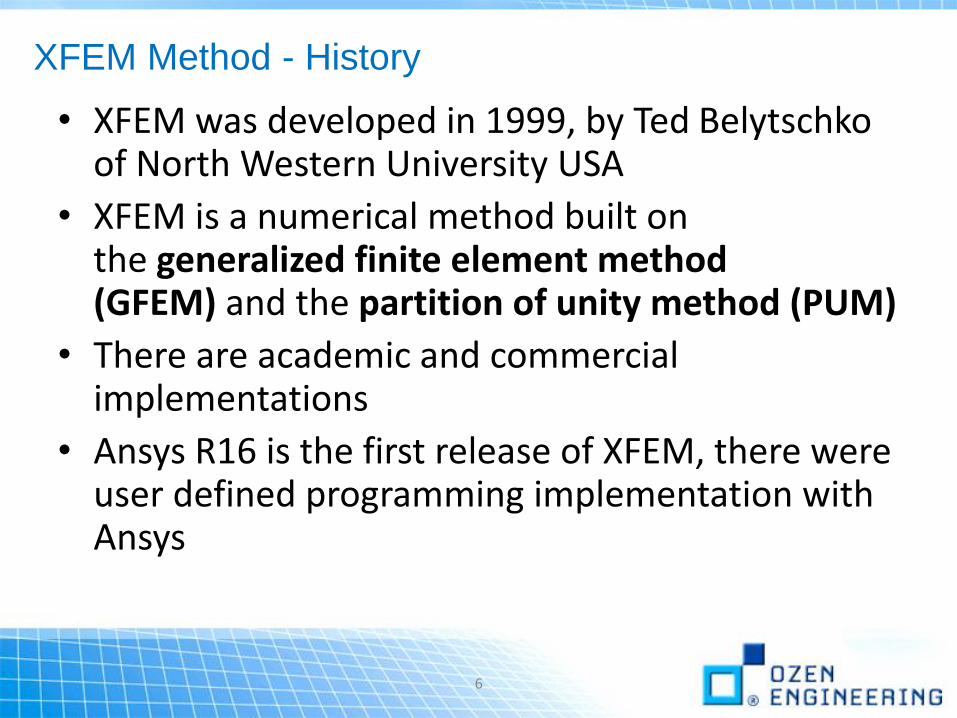
XFEM Method - History
• XFEM was developed in 1999, by Ted Belytschkoof North Western University USA
• XFEM is a numerical method built on the generalized finite element method (GFEM) and the partition of unity method (PUM)
• There are academic and commercial implementations
• Ansys R16 is the first release of XFEM, there were user defined programming implementation with Ansys
6

XFEM Method - Overview
• The techniques used in XFEM can be listed as:– Singularity-Based Approach
• Accounts for crack tip singularities as well as the jumps in displacements across the crack surfaces. Cracks may terminate inside a finite element
– Phantom Node Method• Accounts only for jumps in displacements across the crack surfaces. Crack tip singularity
is not taken into account. Cracks terminate at the edge/face of a finite element.
7

XFEM Method – Crack-Growth Simulation Process
• An XFEM crack-growth simulation is assumed to be quasi-static (i.e. inertial effects are negligible)
8
1. Create a Finite Element Model with an Initial Crack
2. Define the Crack-Growth Criterion3. Define the Decay of Stresses on the Newly
Created Crack Segments4. Specify Cohesive Zone Behavior on Initial Crack5. Perform the Crack-Growth Criterion Evaluation6. Perform the Crack-Growth Calculation

XFEM Step-01: FE model with initial crack
• Define an enrichment region in the model with possible crack propagation
• Multiple initial cracks can be defined in the region• Enrichment region should be limited, as addition of extra internal
nodes in the model requires extra computational time
9
XFENRICH, EncrihmentID, CompName, MAT_ID
Command to define enrichment region
Named assigned to identify enrichment region
Component name which includes the elements for enrichment region
Used to define cohesive zone behavior for crack faces

XFEM Step-01: FE model with initial crack
• Crack geometry in an element is defined by specifying two signed distance functions at the nodes of the element
• The two signed distance functions at the nodes represent the position of the nodes from the crack surface and from the crack front
• PHI cannot be zero!• The initial crack cannot cut the element at the nodes of the element
10
XFDATA, LSM, ELEMNUM, NODENUM, PHI
Command to define initial crack
Element number
Node number
Signed normal distance of the node from crack

XFEM Step-02: Define crack-growth criterion
• Crack-growth criterion must be specified for newly cracked segments• The crack segments are such that they fully cut the elements ahead of the
crack• The crack propagates at the rate of only one element at a time
11
TB, CGCR,,,STTMAX (or PSMAX)• STTMAX (maximum circumferential stress σθθ
criterion)
• PSMAX (circumferential stress criterion based on σrθ=0
• Ideally both criteria gives same or very similar results

XFEM Step-3&4: Define condition for new crack faces
• When cohesive segments are initiated, the cohesive stresses in the crack segments gradually decrease to zero as the deformation progresses
• This behavior can be defined for initial cracks and existing cracks via TB command
• Contact between crack faces are resolved using frictionless contact. This is default behavior and cannot be changed
12
TB, CGCR,,,,RLIN
For Newly Created Crack Segments;Rigid Linear Law is available
TB, CZM,,,,BILI
For Initial Crack Segments;Bilinear Cohesive Law is available
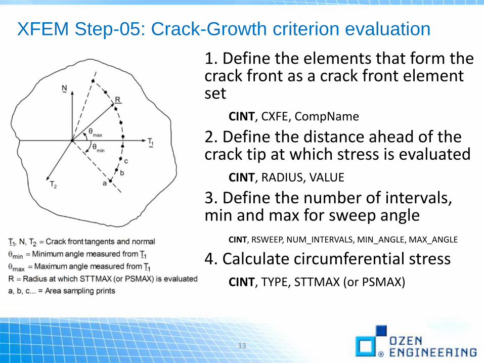
XFEM Step-05: Crack-Growth criterion evaluation
1. Define the elements that form the crack front as a crack front element set
CINT, CXFE, CompName
2. Define the distance ahead of the crack tip at which stress is evaluated
CINT, RADIUS, VALUE
3. Define the number of intervals, min and max for sweep angle
CINT, RSWEEP, NUM_INTERVALS, MIN_ANGLE, MAX_ANGLE
4. Calculate circumferential stressCINT, TYPE, STTMAX (or PSMAX)
13

XFEM Step-06: Crack-Growth calculation
14
1. Initiate the crack-growth set
CGROW, NEW, SET_NUM
2. Specify the crack calculation ID:
CGROW, CID, ID_NUM
3. Specify XFEM crack-growth method
CGROW, METHOD, XFEM
4. Specify the fracture criterion
CGROW, FCOPTION, MTAB, MAT_ID
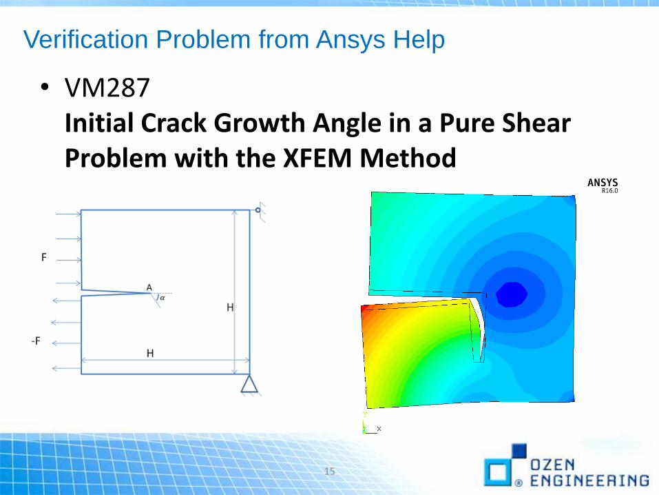
Verification Problem from Ansys Help
• VM287Initial Crack Growth Angle in a Pure Shear Problem with the XFEM Method
15

Verification Problem from Ansys Help
• VM287Initial Crack Growth Angle in a Pure Shear Problem with the XFEM Method
16

Example Problem from Ansys Help
• help/ans_frac/Hlp_G_FRACXFEM.html#d0e5542
Crack Growth in a Three-Point Bending Specimen
17

Example Problem from Ansys Help
• help/ans_frac/Hlp_G_FRACXFEM.html#d0e5542
Crack Growth in a Three-Point Bending Specimen
18
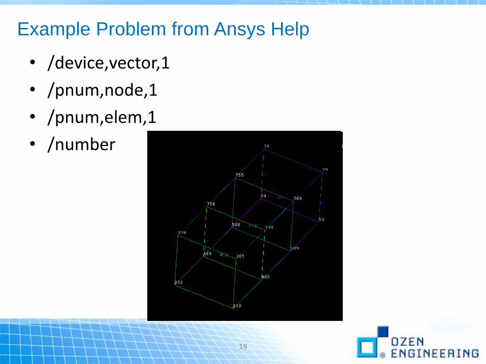
Example Problem from Ansys Help
• /device,vector,1
• /pnum,node,1
• /pnum,elem,1
• /number
19

XFEM Method – Limitations & Assumptions
• Only linear elastic materials can be used in conjunction with the available fracture criteria
• Multiple initial crack can be defined in the region• The XFEM analysis is assumed to be quasi-static, only!• Crack tip singularity effects are not incorporated into the
analysis (ie. Phantom Node Method is the only supported method)
• In 3D XFEM, hexahedral SOLID185 elements are required where crack is initiated and expected to propagate
• Time stepping needs to be small enough to capture crack propagation
• Element birth/death is not supported• Distributed Ansys is not supported
20

Following Week Schedule
• April 9th: 10AM-10:45AM PT Fracture Mechanics with Cohesive Zone and Delamination
• April 16th: 10AM-10:45AM PT Fatigue Crack Propagation
21
www.ozeninc.com

END
Thanks for your attention !!!
Questions ?
CONTACT:OZEN ENGINEERING, INC.
1210 E. ARQUES AVE. SUITE: 207
SUNNYVALE, CA 94085
(408) 732-4665
www.ozeninc.com


![Cross-Parameterization and Compatible Remeshing …...Previous work: Compatible remeshing • Mutual tessellation [Alexa 2000, Schreiner et al. 04] – Intersect meshes in parameter](https://static.fdocuments.net/doc/165x107/5e50a8380dffb5174a5131d4/cross-parameterization-and-compatible-remeshing-previous-work-compatible-remeshing.jpg)