Session 3 Hefner I - NIST
21
Session 3 Session 3 Hefner I Hefner I
Transcript of Session 3 Hefner I - NIST
Session 3Session 3Hefner IHefner I
High Megawatt Fuel Cell Power Converter Technology Impacts Study
(NIST/DOE Interagency Agreement)
Allen HefnerNIST
The Semiconductor Electronics Division
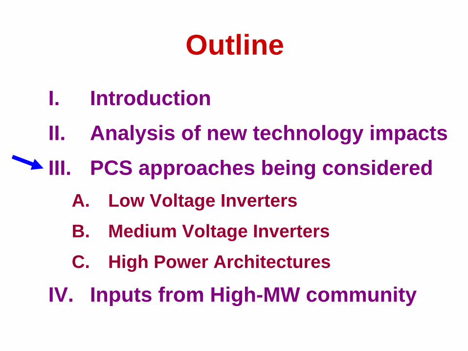
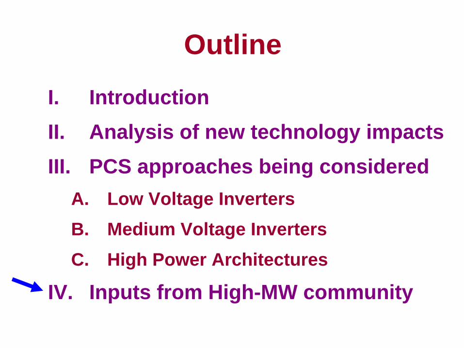
Outline
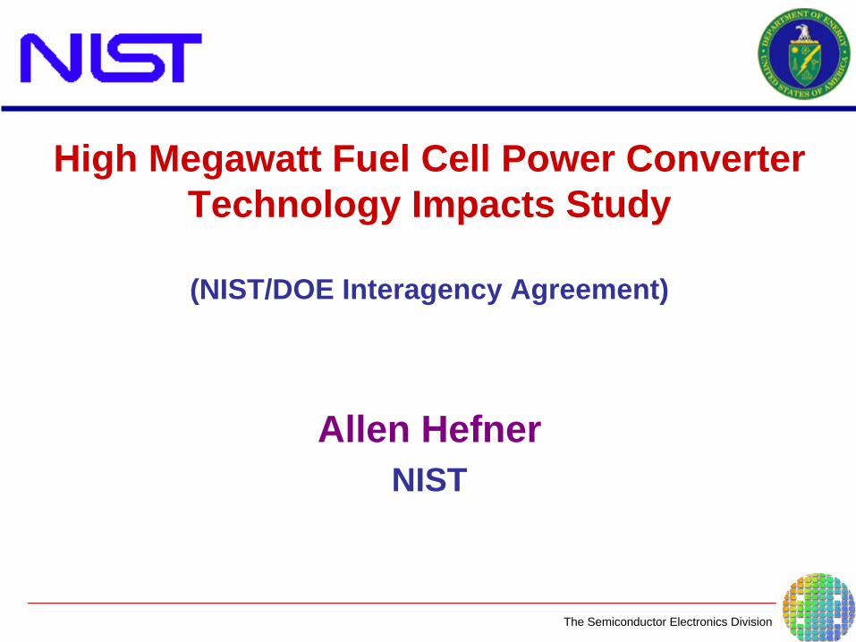
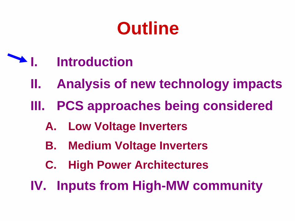
I. IntroductionII. Analysis of new technology impacts III. PCS approaches being considered
A. Low Voltage InvertersB. Medium Voltage InvertersC. High Power Architectures
IV. Inputs from High-MW community
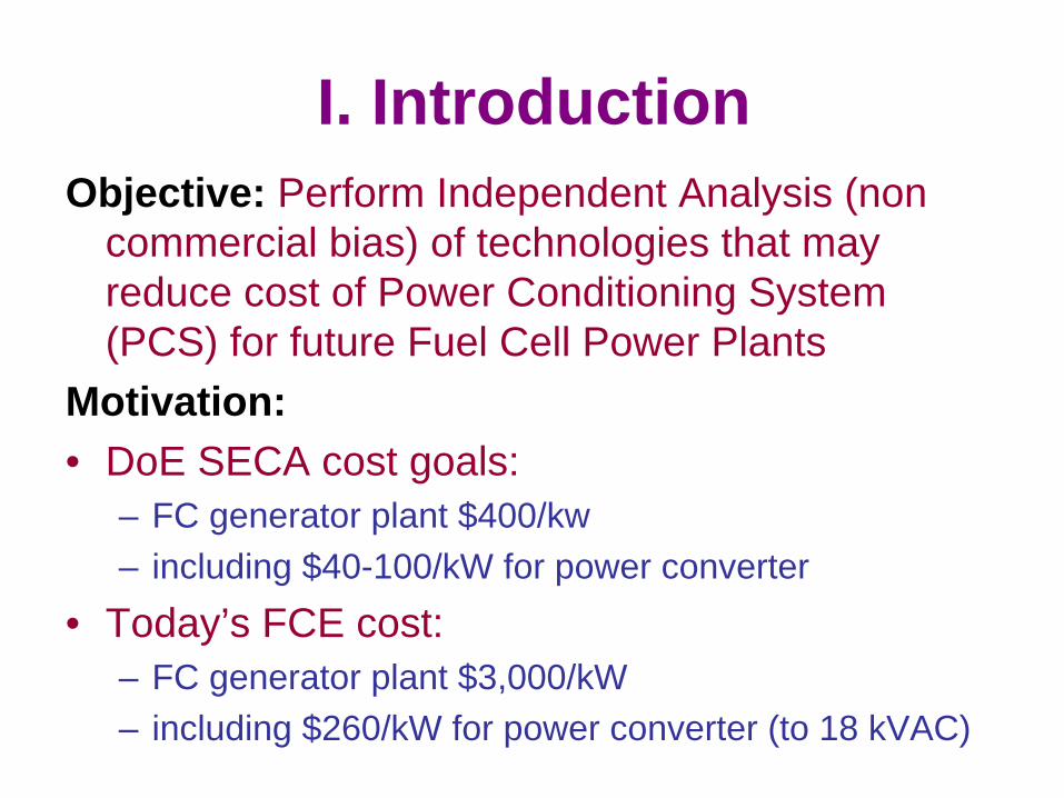
I. IntroductionObjective: Perform Independent Analysis (non
commercial bias) of technologies that may reduce cost of Power Conditioning System (PCS) for future Fuel Cell Power Plants
Motivation:• DoE SECA cost goals:
– FC generator plant $400/kw – including $40-100/kW for power converter
• Today’s FCE cost:– FC generator plant $3,000/kW – including $260/kW for power converter (to 18 kVAC)
Outline
I. IntroductionII. Analysis of new technology impacts III. PCS approaches being considered
A. Low Voltage InvertersB. Medium Voltage InvertersC. High Power Architectures
IV. Inputs from High-MW community
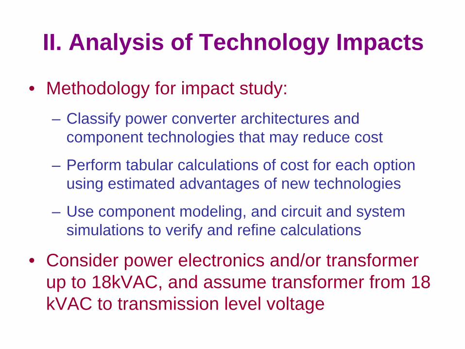
II. Analysis of Technology Impacts
• Methodology for impact study:– Classify power converter architectures and
component technologies that may reduce cost
– Perform tabular calculations of cost for each option using estimated advantages of new technologies
– Use component modeling, and circuit and system simulations to verify and refine calculations
• Consider power electronics and/or transformer up to 18kVAC, and assume transformer from 18 kVAC to transmission level voltage
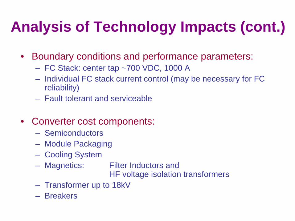
Analysis of Technology Impacts (cont.)
• Boundary conditions and performance parameters:– FC Stack: center tap ~700 VDC, 1000 A– Individual FC stack current control (may be necessary for FC
reliability)– Fault tolerant and serviceable
• Converter cost components:– Semiconductors– Module Packaging– Cooling System– Magnetics: Filter Inductors and
HF voltage isolation transformers– Transformer up to 18kV– Breakers
Outline
I. IntroductionII. Analysis of new technology impacts III. PCS approaches being considered
A. Low Voltage InvertersB. Medium Voltage InvertersC. High Power Architectures
IV. Inputs from High-MW community
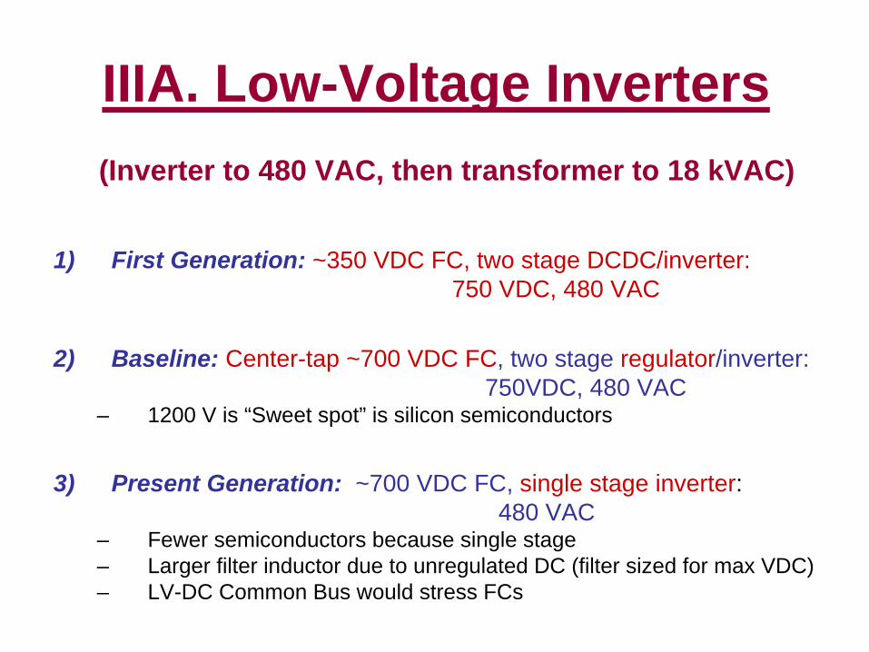
IIIA. Low-Voltage Inverters(Inverter to 480 VAC, then transformer to 18 kVAC)
1) First Generation: ~350 VDC FC, two stage DCDC/inverter: 750 VDC, 480 VAC
2) Baseline: Center-tap ~700 VDC FC, two stage regulator/inverter: 750VDC, 480 VAC
– 1200 V is “Sweet spot” is silicon semiconductors
3) Present Generation: ~700 VDC FC, single stage inverter: 480 VAC
– Fewer semiconductors because single stage– Larger filter inductor due to unregulated DC (filter sized for max VDC) – LV-DC Common Bus would stress FCs
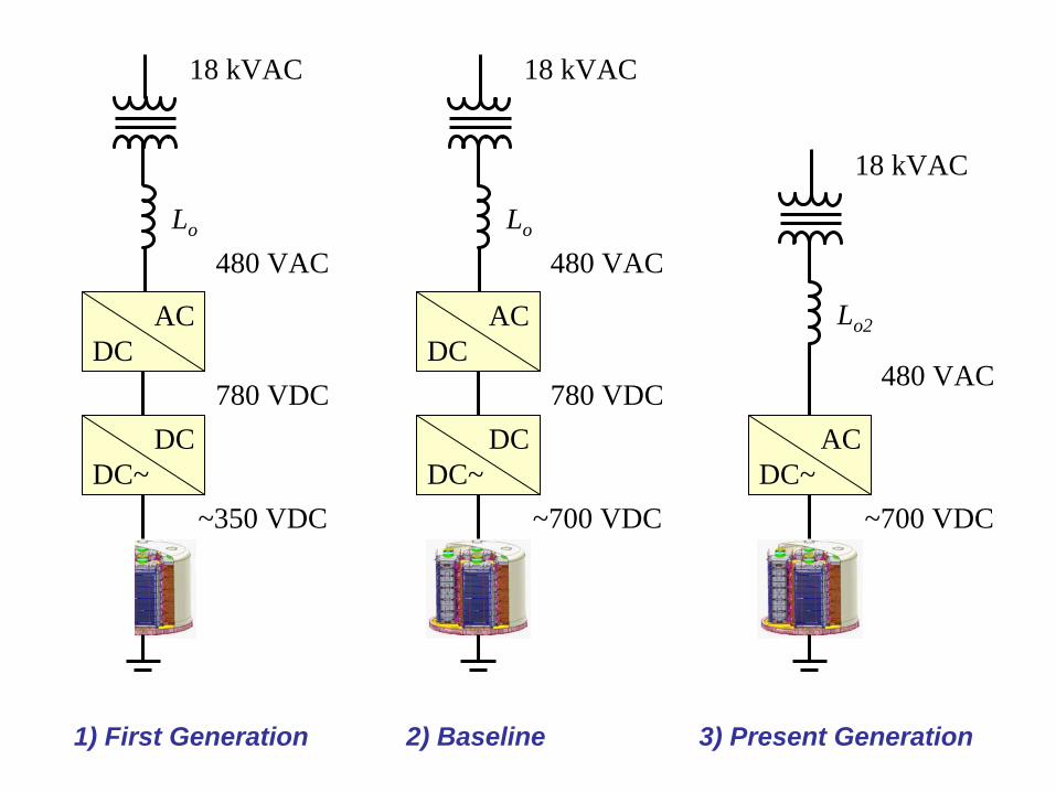
Lo
480 VAC
~350 VDC
DCDC~
ACDC
780 VDC
18 kVAC
Lo
480 VAC
~700 VDC
DCDC~
ACDC
780 VDC
18 kVAC
Lo2
480 VAC
~700 VDC
ACDC~
18 kVAC
1) First Generation 2) Baseline 3) Present Generation

Low-Voltage Semiconductors
• Baseline: 1200 V silicon IGBT switch and silicon PiN diode– 1200 V is sweet spot for silicon IGBTs at 15 – 20 kHz switching
• 1200 V silicon IGBT switch and SiC Schottky diode– More efficient at 20 kHz less heat removal cost
lower temperature and longer life– Less EMI less filter inductor cost– What is cost break point or 1200 V SiC Schottky?
• 1200 V SiC MOSFET Switch and SiC Schottky diode– Higher Frequency for DCDC but not necessary for inverter– What is cost break point for 1200 V SiC MOSFET Switch?
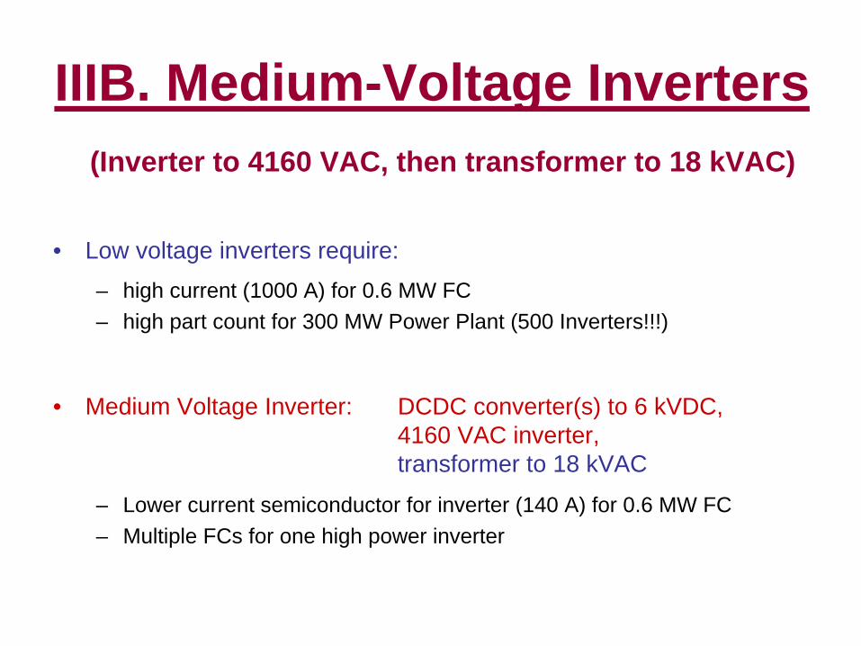
IIIB. Medium-Voltage Inverters(Inverter to 4160 VAC, then transformer to 18 kVAC)
• Low voltage inverters require:– high current (1000 A) for 0.6 MW FC– high part count for 300 MW Power Plant (500 Inverters!!!)
• Medium Voltage Inverter: DCDC converter(s) to 6 kVDC, 4160 VAC inverter, transformer to 18 kVAC
– Lower current semiconductor for inverter (140 A) for 0.6 MW FC– Multiple FCs for one high power inverter
High-Voltage Semiconductors
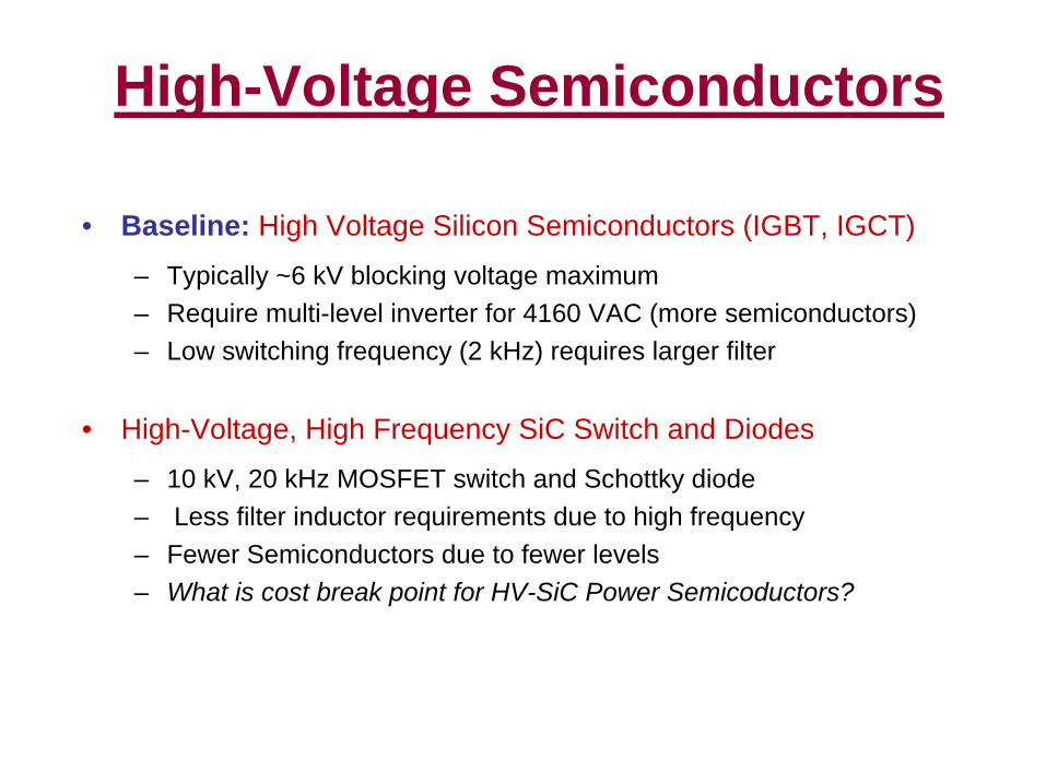
• Baseline: High Voltage Silicon Semiconductors (IGBT, IGCT)
– Typically ~6 kV blocking voltage maximum– Require multi-level inverter for 4160 VAC (more semiconductors)– Low switching frequency (2 kHz) requires larger filter
• High-Voltage, High Frequency SiC Switch and Diodes
– 10 kV, 20 kHz MOSFET switch and Schottky diode– Less filter inductor requirements due to high frequency– Fewer Semiconductors due to fewer levels– What is cost break point for HV-SiC Power Semicoductors?
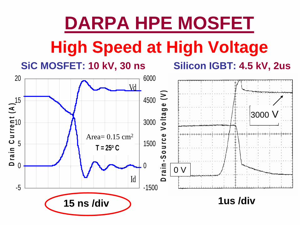
DARPA HPE MOSFET High Speed at High Voltage
-5
0
5
10
15
20
Dra
in C
urre
nt (A
)
-1500
0
1500
3000
4500
6000
Dra
in-S
ourc
e Vo
ltage
(V)
Area = 0.125 cm2
T = 25o C
Vd
Id
SiC MOSFET: 10 kV, 30 ns Silicon IGBT: 4.5 kV, 2us
1us /div
3000 V
15 ns /div
0 V
Area= 0.15 cm2
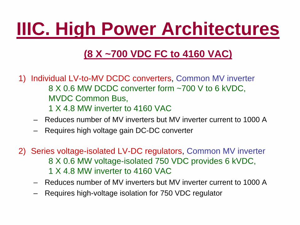
IIIC. High Power Architectures(8 X ~700 VDC FC to 4160 VAC)
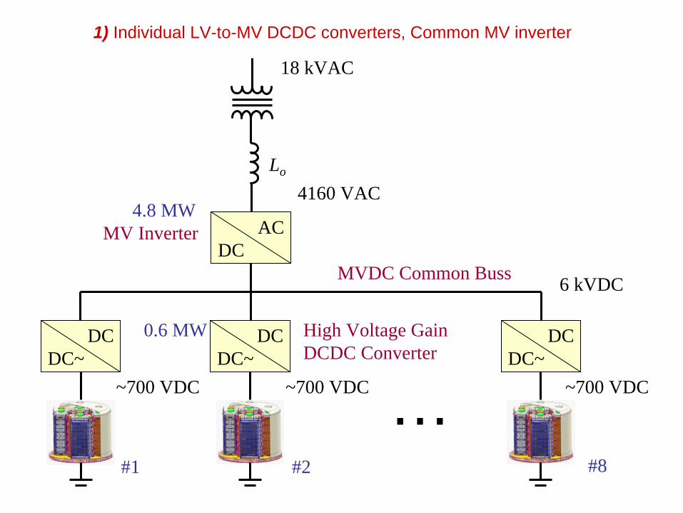
1) Individual LV-to-MV DCDC converters, Common MV inverter 8 X 0.6 MW DCDC converter form ~700 V to 6 kVDC, MVDC Common Bus, 1 X 4.8 MW inverter to 4160 VAC
– Reduces number of MV inverters but MV inverter current to 1000 A– Requires high voltage gain DC-DC converter
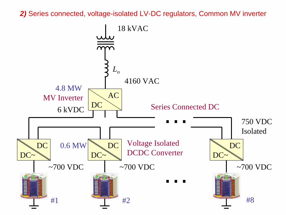
2) Series voltage-isolated LV-DC regulators, Common MV inverter 8 X 0.6 MW voltage-isolated 750 VDC provides 6 kVDC, 1 X 4.8 MW inverter to 4160 VAC
– Reduces number of MV inverters but MV inverter current to 1000 A– Requires high-voltage isolation for 750 VDC regulator

High Power Architectures (Continued)
(8 X ~700 VDC FC to 4160 VAC)
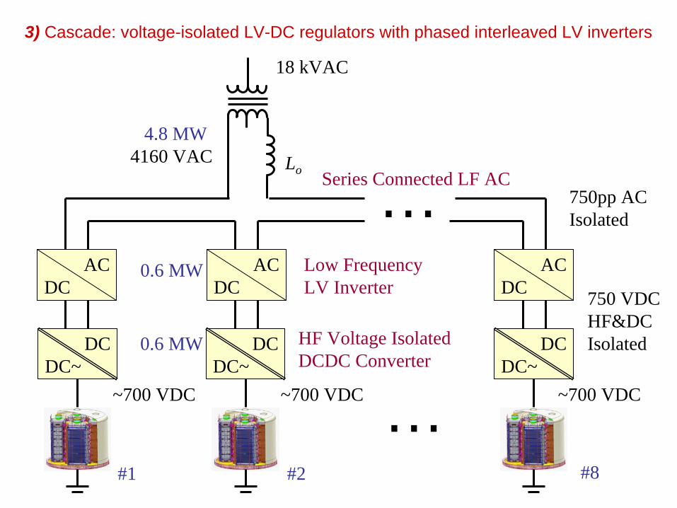
3) Cascade: Series-connected voltage-isolated LV-DC regulators, with low frequency phase-interleaved inverters8 X 0.6 MW voltage-isolated 750 VDC regulators series 8 X 750 V, 2.5 kHz phase interleaved inverters
– Uses 1200 V, 1000 A semiconductors to produce 4160 VAC– 2.5 kHz switching provides effective 20 kHz– improves tradeoff between switching loss and filter size– Requires high-frequency, high-voltage isolation for 750 VDC regulator
Lo
4160 VAC
~700 VDC
DCDC~
ACDC
MVDC Common Buss
18 kVAC
1) Individual LV-to-MV DCDC converters, Common MV inverter
~700 VDC
DCDC~
DCDC~
… ~700 VDC
6 kVDC
High Voltage Gain DCDC Converter
MV Inverter4.8 MW
0.6 MW
#1 #2 #8
Lo
4160 VAC
~700 VDC
DCDC~
ACDC Series Connected DC
18 kVAC
2) Series connected, voltage-isolated LV-DC regulators, Common MV inverter
~700 VDC
DCDC~
DCDC~
… ~700 VDC
750 VDCIsolated
Voltage Isolated DCDC Converter
MV Inverter4.8 MW
0.6 MW
#1 #2 #8
…6 kVDC
Lo4160 VAC
~700 VDC
DCDC~
ACDC
Series Connected LF AC
18 kVAC
3) Cascade: voltage-isolated LV-DC regulators with phased interleaved LV inverters
~700 VDC
DCDC~
DCDC~
… ~700 VDC
750 VDCHF&DCIsolatedHF Voltage Isolated
DCDC Converter
4.8 MW
0.6 MW
#1 #2 #8
…AC
DCAC
DC
750pp ACIsolated
Low FrequencyLV Inverter
0.6 MW
Outline
I. IntroductionII. Analysis of new technology impacts III. PCS approaches being considered
A. Low Voltage InvertersB. Medium Voltage InvertersC. High Power Architectures
IV. Inputs from High-MW community
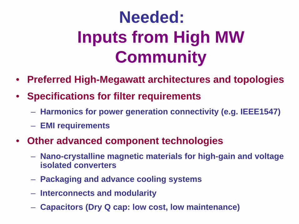
Needed: Inputs from High MW
Community• Preferred High-Megawatt architectures and topologies• Specifications for filter requirements
– Harmonics for power generation connectivity (e.g. IEEE1547) – EMI requirements
• Other advanced component technologies– Nano-crystalline magnetic materials for high-gain and voltage
isolated converters– Packaging and advance cooling systems– Interconnects and modularity– Capacitors (Dry Q cap: low cost, low maintenance)