ses Model RAGN Maal Glass ROTAMETERA Rotameter measures the flow of liquids, gases and steam by...
46
User´s Manual Model RAGN Glass ROTAMETER IM 01R01B10-00E-E Rota Yokogawa GmbH & Co. KG Rheinstr. 8 D-79664 Wehr Germany IM 01R01B10-00E-E ©Copyright 2011 (Rü) 2nd edition: November 2011 (Rü)
Transcript of ses Model RAGN Maal Glass ROTAMETERA Rotameter measures the flow of liquids, gases and steam by...
User´sManual
Model RAGNGlass ROTAMETER
IM 01R01B10-00E-E
Rota Yokogawa GmbH & Co. KGRheinstr. 8D-79664 WehrGermany
IM 01R01B10-00E-E©Copyright 2011 (Rü)
2nd edition: November 2011 (Rü)

Blank Page

<CONTENTS> i
IM 01R01B10-00E-E 2nd edition: November 01, 2011-00All Rights Reserved. Copyright © 2011, Rota Yokogawa
Contents
1. Introduction .........................................................................................1-1
1.1 ATEX Documentation ......................................................................................1-3
1.2 General description .........................................................................................1-4
1.3 Principle of measurement ..............................................................................1-4
1.4 Intended use ....................................................................................................1-4
2. Transportation and Storage ..............................................................2-1
3. Product description ...........................................................................3-1
3.1 Metering Tube ..................................................................................................3-1
3.2 Bistable inductive ring sensor (Option /GR2 to /GR8) ...............................3-2
3.3 Magnetic contact (Option /GM1 to /GM5) .....................................................3-2
3.4 Marking ............................................................................................................3-3
4. Installation ...........................................................................................4-1
4.1 General .............................................................................................................4-1
4.2 Piping ...............................................................................................................4-2
4.3 Bistable inductive ring sensor (Option /GR2 to /GR8) ...............................4-3
4.4 Magnetic contact (Option /GM1 to /GM5) .....................................................4-4
4.5 Connection box (Option /GD1 or /GD2) ........................................................4-5
5. Service ................................................................................................5-1
5.1 Customer maintenance part list (CMPL) ......................................................5-1
5.2 Template for sending back to service ..........................................................5-4
6. Explosion protected type instruments ............................................6-1
6.1 Bistable inductive ring sensor (Option /GR2 to /GR8) ...............................6-1
6.2 Magnetic contact (Option /GM1 to /GM5) .....................................................6-3
7. Instructions for PED ...........................................................................7-1
8. Technical Data ....................................................................................8-1
<Contents>ii
IM 01R01B10-00E-E 2nd edition: November 01, 2011-00 All Rights Reserved. Copyright © 2011, Rota Yokogawa
APPENDIX 1. Safety Instrumented Systems Installation .................. A1-1
A1.1 Scope and Purpose ................................................................................... A1-1
A1.2 Using RAGN for a SIS Application ........................................................... A1-1
A1.2.1 Safety Function .................................................................................................A1-1
A1.2.2 Diagnostic Response Time ..............................................................................A1-2
A1.2.3 Setup ..................................................................................................................A1-2
A1.2.4 Proof Testing .....................................................................................................A1-2
A1.2.5 Repair and replacement ...................................................................................A1-2
A1.2.6 Startup Time ......................................................................................................A1-3
A1.2.7 Reliability data ..................................................................................................A1-3
A1.2.8 Lifetime limits .................................................................................................A1-3
A1.2.9 Environmental limits .........................................................................................A1-3
A1.2.10 Application limits ............................................................................................A1-3
A1.3 Definitions and Abbreviations ................................................................... A1-4
A1.3.1 Definitions .........................................................................................................A1-4
A1.3.2 Abbreviations ....................................................................................................A1-4
A1.4 Assessment results .................................................................................... A1-4
A1.4.1 Safety related parameters ................................................................................A1-4
<1. INTRODUCTION> 1-1
IM 01R01B10-00E-E 2nd edition: November 01, 2011-00All Rights Reserved. Copyright © 2011, Rota Yokogawa
1. Introduction
Before use, read this manual thoroughly andfamiliarize yourself fully with the features,operations and handling of Rotameter RAGN to have the instrument deliver its full capabilities andto ensure its efficient and correct use.
Notices Regarding This Manual• This manual should be passed to the end user.• The contents of this manual are subject to change without prior notice.• All rights reserved. No part of this document may be reproduced or transmitted in any form or by any means without the written permission of Rota Yokogawa (hereinafter simply referred to as Yokogawa).• This manual neither does warrant the marketability of this instrument nor it does warrant that the instrument will suit a particular purpose of the user.• Every effort has been made to ensure accuracy in the contents of this manual. However, should any questions arise or errors come to your attention, please contact your nearest Yokogawa sales office that appears on the back of this manual or the sales representative from which you purchased the product.• This manual is not intended for models with custom specifications.• Revisions may not always be made in this manual in conjunction with changes in specifications, constructions and/or components if such changes are not deemed to interfere with the instrument’s functionality or performance.
Notices Regarding Safety and Modification• For the protection and safety of personnel, the instrument and the system comprising the instrument, be sure to follow the instructions on safety described in this manual when handling the product. If you handle the instrument in a manner contrary to these instructions, Yokogawa does not guarantee safety.• If this instrument is used in a manner not specified in this manual, the protection provided by this instrument may be impaired.• As for explosion proof model, if you yourself repair or modify the instrument and then fail to return it to its original form, the explosion protected construction of the instrument will be impaired, creating a hazardous condition. Be sure to consult Yokogawa for repairs and modifications.
The following safety symbols and cautionarynotes are used on the product and in this manual:
This symbol is used to indicate that a hazardouscondition will result which, if not avoided, may lead to loss of life or serious injury. This manualdescribes how the operator should exercise care to avoid such a risk..
This symbol is used to indicate that a hazardouscondition will result which, if not avoided, may lead to minor injury or material damage. This manual describes how the operator should exercise care to avoid a risk of bodily injury or damage to the instrument.
This symbol is used to call your attention to acondition that must be observed in order to avoidthe risk of damage to the instrument or systemproblems.
This symbol is used to call your attention toinformation that should be referred to in order toknow the operations and functions of theinstrument.
For Safe Use of Rotameter RAGN
• If the process fluid is harmful to personnel, handle Rotameter RAGN carefully even after it has been removed from the process line for maintenance or other purposes. Exercise extreme care to prevent the fluid from coming into contact with human flesh and to avoid inhaling any residual gas.• In case of Explosion proof type instrument, further requirements and differences are described in Chapter 6 "EXPLOSION PROTECTED TYPE INSTRUMENTS”. The description in Chapter 6 is prior to other descriptions in this instruction manual.
WARNING
CAUTION
IMPORTANT
NOTE
WARNING

<1. INTRODUCTION>1-2
IM 01R01B10-00E-E 2nd edition: November 01, 2011-00 All Rights Reserved. Copyright © 2011, Rota Yokogawa
Warranty• The warranty of this instrument shall cover the period noted on the quotation presented to the Purchaser at the time of purchase. The Seller shall repair the instrument free of charge when the failure occurred during the warranty period.• All inquiries on instrument failure should be directed to the Seller’s sales representative from whom you purchased the instrument or your nearest sales office of the Seller.• Should the instrument fail, contact the Seller specifying the model and instrument number of the product in question. Be specific in describing details on the failure and the process in which the failure occurred. It will be helpful if schematic diagrams and/or records of data are attached to the failed instrument.• Whether or not the failed instrument should be repaired free of charge shall be left solely to the discretion of the Seller as a result of an inspection by the Seller.
The Purchaser shall not be entitled toreceive repair services from the Seller freeof charge, even during the warranty period,if the malfunction or damage is due to:• improper and/or inadequate maintenance of the instrument in question by the Purchaser.• handling, use or storage of the instrument in question beyond the design and/or specifications requirements.• use of the instrument in question in a location not conforming to the conditions specified in the Seller’s General Specification or Instruction Manual.• retrofitting and/or repair by an other party than the Seller or a party to whom the Seller has entrusted repair services.• improper relocation of the instrument in question after delivery.• reason of force measure such as fires, earthquakes, storms/ floods, thunder/lightning, or other reasons not attributable to the instrument in question.• YOKOGAWA gives no warranty for the improper use of glass flow meters. Due to the uncontrollably of the material YOKOGAWA cannot guarantee that the material is fracture-proof.
• When removing the instrument from hazardous processes, avoid contact with the fluid and the interior of the meter.• In case of Explosion proof type instrument, further requirements and differences are described in Chapter 6 " EXPLOSION PROTECTED TYPE INSTRUMENTS”. The description in Chapter 6 is prior to other descriptions in this instruction manual.
Notices regarding EMCThe Rotameter RAGN with option /GR2 ... /GR8 is conform to the European EMC Guideline and fulfills the following standards: DIN EN 61000-4-2 : level 3DIN EN 61000-4-3 : level 2DIN EN 61000-4-4 : level 3DIN EN 61000-4-6 : level 2DIN EN 55011 : group 1 / class AThe RAGN with option /GR2 ... /GR8 is a class A product and should be used and installed properly according to the EMC Class A requirements.
Although the inductive ring sensor has been designed to resist high frequency electrical noise, if a radio transceiver is used near the transmitter or it external wiring, the transmitter may be affected by high frequency noise pickup. To test for such effects, bring the transceiver in use slowly from a distance of several meters from the transmitter, and observe the measurement loop for noise effects. Thereafter, always use the transceiver outside the area affected by noise.
WARNING
IMPORTANT
<1. INTRODUCTION> 1-3
IM 01R01B10-00E-E 2nd edition: November 01, 2011-00All Rights Reserved. Copyright © 2011, Rota Yokogawa
1.1 ATEX DocumentationThis is only applicable to the countries in European Union.
GB
DK
I
E
NL
SF
P
F
D
S
LT
LV
PL
EST
SLO
H
BG
RO
M
CZ
SK
GR

<1. INTRODUCTION>1-4
IM 01R01B10-00E-E 2nd edition: November 01, 2011-00 All Rights Reserved. Copyright © 2011, Rota Yokogawa
A Rotameter measures the flow of liquids, gases and steam by using a float inside a conical tube.The gap between the tube and float is larger at the top to allow a greater flow to pass through the meter. As gravity works in a vertical orientation so the tube needs to be vertically oriented.Rota Yokogawa developed the free rotating float which stabilises its position in the centre of the cone to provide a more stable flow measurement.The medium passes through the metering tube from bottom to top and consequently rises the float until there is an annular gap between the inside surface of the metering tube and the float and equilibrium of the following forces has been achieved.
Buoyancy / Gravity / Friction force
The Rotameter principle is one of the oldest and mature principles in flow measurement. This mechanical principle is as simple as it is reliable. The flow is indicated by the top of the float and can be read from the standard scale on the metering tube. The RAGN can be equipped with limit switches option /GR2 to /GR8 and /GM1 to /GM5.All units are calibrated with water or air by the manufacturer. By adjusting the calibration values to the measured substance’s state of aggregation (density, viscosity), the flow rate scale for each measuring tube can be determined.When the process conditions have changed the scale is not accurate any longer and the glass tube needs to be replaced.
1.2 General descriptionThis manual describes installation, operation and maintenance of the RAGN. Please read it carefully before using this device.Further, please note that customer features are not described in this manual. When modifying specifications,construction or parts, this manual is not necessarily revised unless it can be assumed that these changes willimpair RAGN functions or performance.All units are thoroughly tested before shipping. Please check the received units visually to ensure that theyhave not been damaged during transport. In case of defects or questions please contact your nearestYOKOGAWA service centre or sales office. Please describe any defect precisely and indicate model code aswell as serial number.YOKOGAWA refuses any liability for units which have been repaired by the user without prior consent and donot meet the specifications as a consequence.
1.3 Principle of measurement
1.4 Intended useThe RAGN is designed for the continuous flow measurement of liquids or gases and can be used in all industries. Typical applications are:- Visual fluid monitoring- Industrial gas measurement- Controlling of water circuits
FG = FF + FB = Equilibrium
R
10
20
30
40
50
60
70
80
90
100l/h
Equilibrium
FG
FB
FF
<2. TRANSORTATION AND STORAGE> 2-1
IM 01R01B10-00E-E 2nd edition: November 01, 2011-00All Rights Reserved. Copyright © 2011, Rota Yokogawa
Transportation instructions
When transporting the instrument, you must observe the following safety instructions in order to avoid lethal
injury, damage to the instrument and other material damage.
The steps involved in transport may only be carried out by qualified persons taking into account the safety
instructions.
• Observe the transport instructions on the packaging.
• Observe the below mentioned storage conditions.
• Use only the original packaging.
• The packaging material must be disposed of in accordance with the regulations.
• The transport braces must not be removed until installation.
• Read the chapter “Safety instructions”.
• To avoid any damages, unpack the flow meter only at the installation site.
• Mechanical shocks are to be avoided.
Storage conditions
Please note the following for storage purposes :
• The instrument should be stored in its transport packaging.
• Choose a storage place that meets the following requirements:
• Protection from rain and humidity• Free of mechanical vibration and shocks• Ambient temperature between -25°C to 60°C
• Atmospheric humidity ranging from 0 to 100%. Operation above 95% for longer times is not recommended
Before storing a used flow meter remove any fluid from the flow meter and clean it in order to avoid fouling.
Properties of the instrument can change when stored outdoors.
2. Transportation and Storage
<2. TRANPORTATION AND STORAGE>2-2
IM 01R01B10-00E-E 2nd edition: November 01, 2011-00 All Rights Reserved. Copyright © 2011, Rota Yokogawa
Blank Page
<3. PRODUCT DESCRIPTION> 3-1
IM 01R01B10-00E-E 2nd edition: November 01, 2011-00All Rights Reserved. Copyright © 2011, Rota Yokogawa
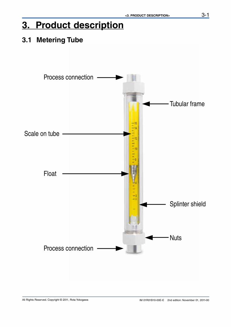
3. Product description
3.1 Metering Tube
Process connection
Process connection
Float
Scale on tube
Nuts
Tubular frame
Splinter shield
<3. PRODUCT DESCRIPTION>3-2
IM 01R01B10-00E-E 2nd edition: November 01, 2011-00 All Rights Reserved. Copyright © 2011, Rota Yokogawa
3.2 Bistable inductive ring sensor (Option /GR2 to /GR8)
The ring sensor type RI20 is intended for connection to glass Rotameters. It indicates whether the float is
positioned above or below the sensor.
The float must have ferromagnetic properties (e.g. a PVDF float with iron core).
The device is offered into 3 versions:
Type Option Diameter of tube Possible float (Yokogawa Code)
RI20-10 G /GR2, /GR6 10mm -PD B_N
RI20-17 K /GR3, /GR7 17mm -PD C_N
RI20-17 G /GR4, /GR8 17mm -PD D_N
The RI20 is bistable, i.e. if the float is below the switch point, current consumption is always < 1 mA and it is
> 2.2 mA, if the float is above the switch point. After power on or after power fail the RI20 shows
I < 1 mA. To find the correct float position the float has to move once through the RI20.
It is intended for connection to a non-bistable isolation-switch amplifier complying with DIN EN 50227
(NAMUR) (e.g. options /Wxx). With its plastic housing and its sealed-in electronic equipment, the RI20
meets the requirements for protection class IP67 and can also be operated safely in aggressive
atmospheres.
The RI20 is maintenance-free.
See chapter 6 "EXPLOSION PROTECTED TYPE INSTRUMENTS” for devices in ATEX version.
3.3 Magnetic contact (Option /GM1 to /GM5)
The limit switch is mounted to a Rotameter type RAGN, if a magnetic float is used and indicates if the flow falls below the set limit (MIN-contact) or exceeds the set limit (MAX-contact).When reaching the switch point the Reed contact with bias by a permanent magnet opens when the float enters the alarm range. The Reed contact closes when the float leaves the alarm range. Opened or closed the Reed contact remains because of its bistability in its position no matter how far the float moves away.Due to the low switch output of the Reed contact (max, 10 VA/(W), max. 0.5 A, max. 230 V AC) a transformer isolated barrier (e.g. option /Wxx) should be connected to the GM.

<3. PRODUCT DESCRIPTION> 3-3
IM 01R01B10-00E-E 2nd edition: November 01, 2011-00All Rights Reserved. Copyright © 2011, Rota Yokogawa
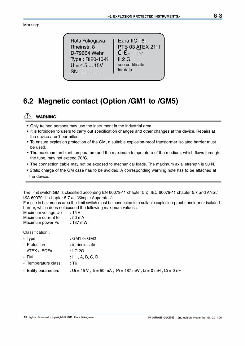
3.4 MarkingName plate of RAGN:
Name plate of inductive ring sensor (option /GR2 to /GR8)
Rota YokogawRheinstr. 8D-79664 WehrType : RI20-10-KU = 4.5 ... 15VSN : ..............
ROTA YOKOGAWA D-79664 Wehr
S/N D1L301985RAGN01-D4SS-L624-TTBLN/B1/B4/L12/V1/GM1/GD/MN/P6/H1
PS:16bar TS:-25°C-100°C PTmax:24bar100% = 650 l/min Wasser 20°CTag-No:123456789012345678901234567890123456789012345
KCC-REM-RYG-GR-RAGN
*)**)
*) only for RAGN04, RAGN05, RAGN06 **) only with option /KC
Rota YokogawRheinstr. 8D-79664 WehrType : RI20-10-KU = 4.5 ... 15VSN : ..............
Rota YokogawaRheinstr. 8D-79664 WehrType : RI20-10-KU = 4.5 ... 15VSN : ..............

<3. PRODUCT DESCRIPTION>3-4
IM 01R01B10-00E-E 2nd edition: November 01, 2011-00 All Rights Reserved. Copyright © 2011, Rota Yokogawa
Blank Page

<4. INSTALLATION> 4-1
IM 01R01B10-00E-E 2nd edition: November 01, 2011-00All Rights Reserved. Copyright © 2011, Rota Yokogawa
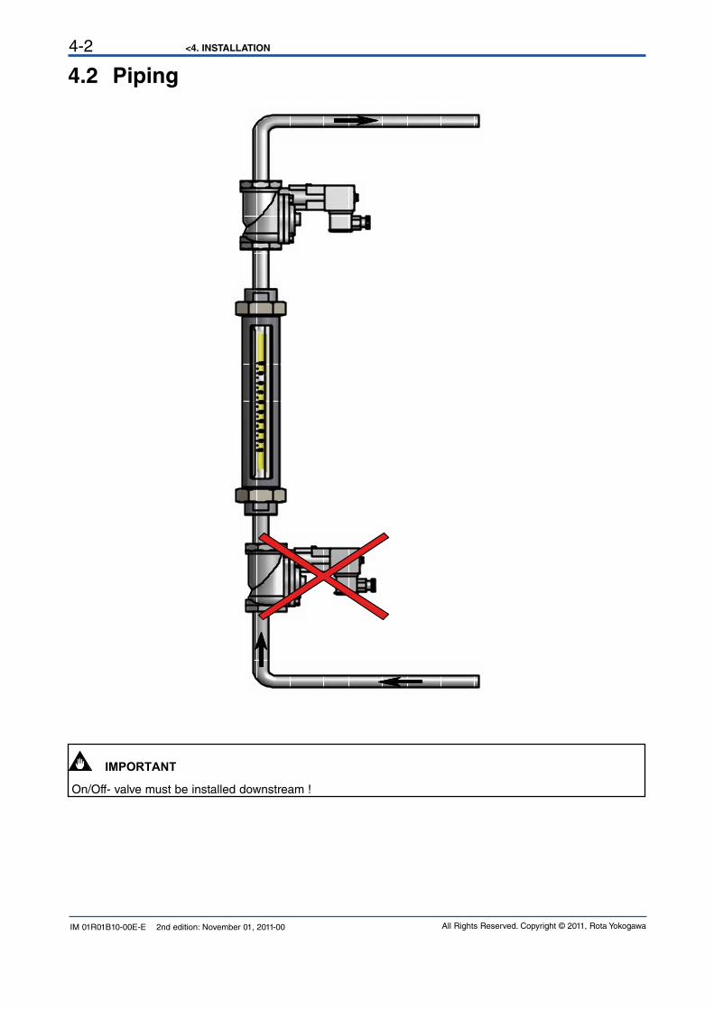
4. Installation4.1 GeneralInstallation: All packaging material must be removed. The transportation lock for the float must be removed. The piping shall be flushed before installing the flowmeter. Piping must be dried for gas applications. Rota-meters must be installed vertically. The flow direction is from bottom to top. Prevent the device from mechani-cal stress and vibration by aligning and supporting the piping. Avoid large volumes of gas downstream and upstream of the device, this can cause vibration due to compression. Install the On/Off valve downstream in order to avoid damage when opening the valve. In case of gas applications, increase the flow pressure slowly. Avoid pressure surges and temperature shocks to the flowmeter at any time. Refer to the pressure and temperature limits of the device. For flowmeters with limit switches please see chapter 4.3, 4.4 and 4.5. Further installation hints can be found in VDI/VDE 3513 sheet 3.
Commissioning:When functioning properly, the float moves freely in the flow. With floats with notches this can be easily seen by their rotation. If the float does not move, please check the installation. The flow rate can be read directly from the scale on the tube. Refer to the scale mark to which the float adjusts its top edge when reading.
Maintenance:With common applications and normal operating conditions the device is maintenance free. In case of soiling we recommend to clean the measuring tube by using a bottle brush and soap water. Make sure not to scratch the measuring tube. If float or measuring tube show signs of wear and tear, we recommend replacing them.
<4. INSTALLATION4-2
IM 01R01B10-00E-E 2nd edition: November 01, 2011-00 All Rights Reserved. Copyright © 2011, Rota Yokogawa
4.2 Piping
IMPORTANT On/Off- valve must be installed downstream !
<4. INSTALLATION> 4-3
IM 01R01B10-00E-E 2nd edition: November 01, 2011-00All Rights Reserved. Copyright © 2011, Rota Yokogawa
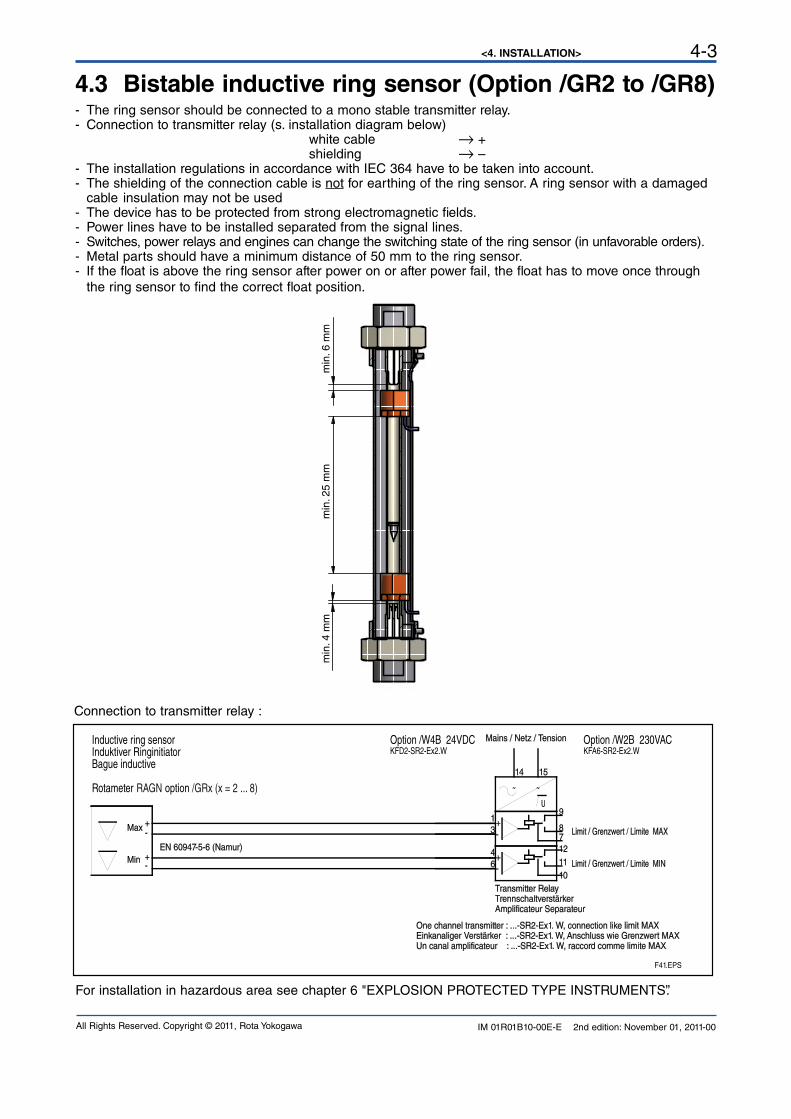
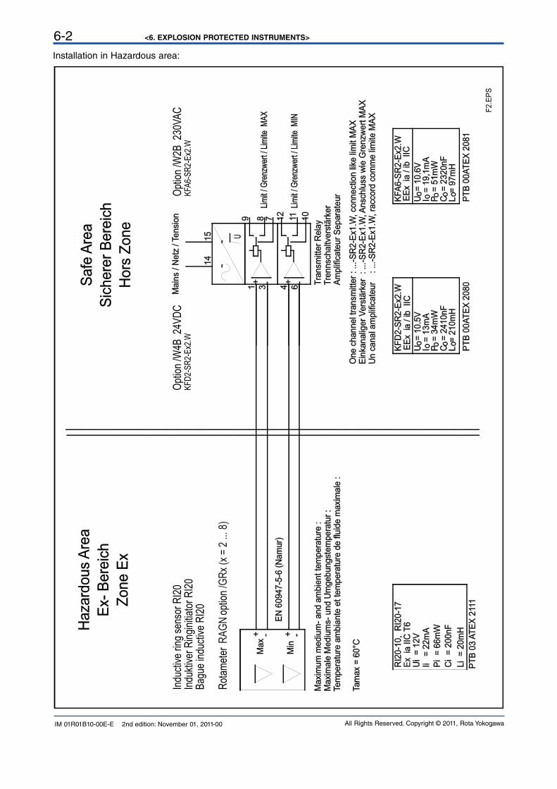
4.3 Bistable inductive ring sensor (Option /GR2 to /GR8)- The ring sensor should be connected to a mono stable transmitter relay.- Connection to transmitter relay (s. installation diagram below) white cable → + shielding → –- The installation regulations in accordance with IEC 364 have to be taken into account.- The shielding of the connection cable is not for earthing of the ring sensor. A ring sensor with a damaged cable insulation may not be used- The device has to be protected from strong electromagnetic fields.- Power lines have to be installed separated from the signal lines.- Switches, power relays and engines can change the switching state of the ring sensor (in unfavorable orders).- Metal parts should have a minimum distance of 50 mm to the ring sensor.- If the float is above the ring sensor after power on or after power fail, the float has to move once through the ring sensor to find the correct float position.
15
46
31
14
12
1011
87
9U
Mains / Netz / Tension
One channel transmitter : ...-SR2-Ex1. W, connection like limit MAXEinkanaliger Verstärker : ...-SR2-Ex1. W, Anschluss wie Grenzwert MAXUn canal amplificateur : ...-SR2-Ex1. W, raccord comme limite MAX
Transmitter RelayTrennschaltverstärkerAmplificateur Separateur
Limit / Grenzwert / Limite MIN
Limit / Grenzwert / Limite MAXMax
MinEN 60947-5-6 (Namur)
-+
-+
~ ~
+-
+-
Option /W4B 24VDCKFD2-SR2-Ex2.W
Option /W2B 230VACKFA6-SR2-Ex2.W
Inductive ring sensor Induktiver Ringinitiator Bague inductive
Rotameter RAGN option /GRx (x = 2 ... 8)
F41.EPS
Connection to transmitter relay :
For installation in hazardous area see chapter 6 "EXPLOSION PROTECTED TYPE INSTRUMENTS”.
min
. 6 m
mm
in. 4
mm
min
. 25
mm

<4. INSTALLATION4-4
IM 01R01B10-00E-E 2nd edition: November 01, 2011-00 All Rights Reserved. Copyright © 2011, Rota Yokogawa
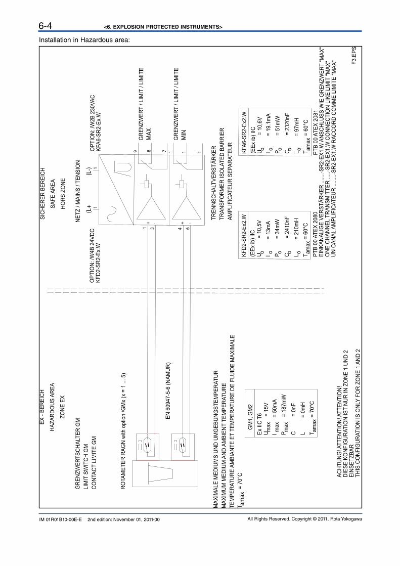
4.4 Magnetic contact (Option /GM1 to /GM5)a) Loose the nut at the guide sleeve.b) If 2 limit switches were ordered install the Max-contact in the top position and the Min- contact in the low position (see print on housing).c) Put the limit switch from the outer side on the guide rail of the Rotameter. d) Adjust the distance between limit switch to tube to 1 mm; check function and correct if necessary.e) Fix limit switch with the nut to guide rail.
Optional connection box /GD1
Limit switch /GM1 or /GM2
Float with magnet
Nut
F45.EPS
GRENZWERTSCHALTER GMLIMIT SWITCH GM
CONTACT LIMITE GM
ROTAMETER RAGN with option /GMx (x = 1 ... 5)
EN 60947-5-6 (NAMUR)
MAINS / NETZ / TENSION
OPTION: /W4B 24VDCKFD2-SR2-Ex.W
OPTION: /W2B 230VACKFA6-SR2-Ex.W
9
8
1
1
1
7
1 1
1
3
4
6
+-
+
-
LIMIT/ GRENZWERT/ LIMITEMAX
MIN
ÄTRENNSCHALTVERST RKERTRANSFORMER ISOLATED BARRIER
AMPLIFICATEUR SEPARATEUR
(L+ (L-)
EINKANALIGE VERSTÄRKER .......-SR2-EX1.W ANSCHLUSS WIE GRENZWERT "MAX"ONE CHANNEL TRANSMITTER .....-SR2-EX1.W CONNECTION LIKE LIMIT "MAX"
UN CANAL AMPLIFICATEUR ........-SR2-EX1.W RACCORD COMME LIMITE "MAX"
LIMIT/ GRENZWERT/ LIMITE
Connection to transmitter relay :
<4. INSTALLATION> 4-5
IM 01R01B10-00E-E 2nd edition: November 01, 2011-00All Rights Reserved. Copyright © 2011, Rota Yokogawa
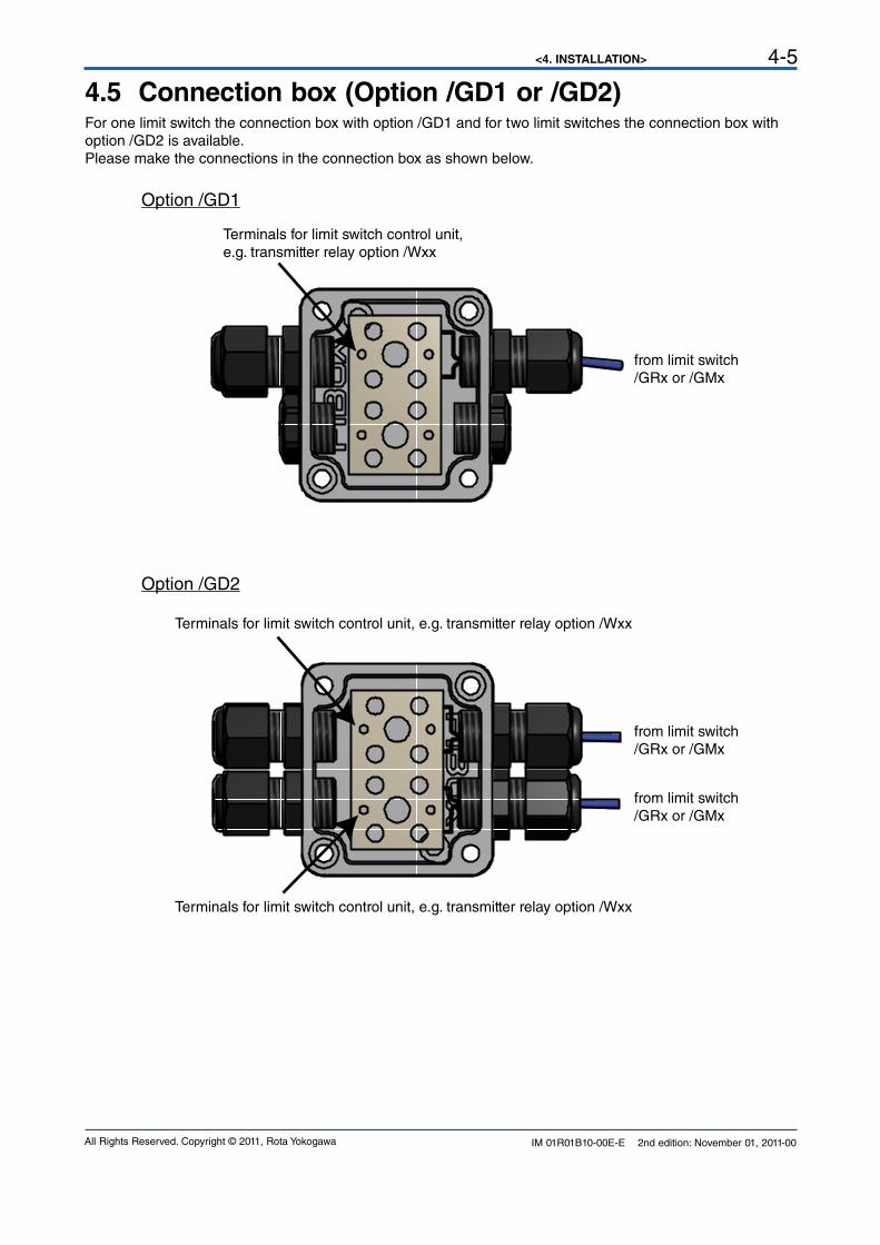
4.5 Connection box (Option /GD1 or /GD2)For one limit switch the connection box with option /GD1 and for two limit switches the connection box with option /GD2 is available. Please make the connections in the connection box as shown below.
Option /GD1
Option /GD2
from limit switch/GRx or /GMx
from limit switch/GRx or /GMx
from limit switch/GRx or /GMx
Terminals for limit switch control unit,e.g. transmitter relay option /Wxx
Terminals for limit switch control unit, e.g. transmitter relay option /Wxx
Terminals for limit switch control unit, e.g. transmitter relay option /Wxx

<4. INSTALLATION4-6
IM 01R01B10-00E-E 2nd edition: November 01, 2011-00 All Rights Reserved. Copyright © 2011, Rota Yokogawa
Blank Page
<5. SERVICE> 5-1
IM 01R01B10-00E-E 2nd edition: November 01, 2011-00All Rights Reserved. Copyright © 2011, Rota Yokogawa
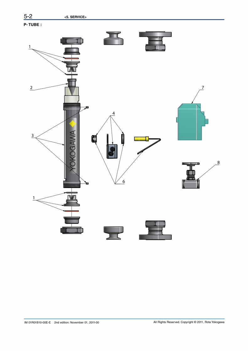
5. Service
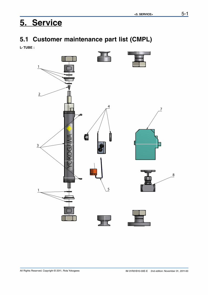
5.1 Customer maintenance part list (CMPL)L- TUBE :
1
3
2
1
4
5
8
7
<5. SERVICE>5-2
IM 01R01B10-00E-E 2nd edition: November 01, 2011-00 All Rights Reserved. Copyright © 2011, Rota Yokogawa
P- TUBE :
1
2
3
1
4
6
7
8

<5. SERVICE> 5-3
IM 01R01B10-00E-E 2nd edition: November 01, 2011-00All Rights Reserved. Copyright © 2011, Rota Yokogawa
Item Part-No. Descriptions
L6 tu
be
L7 tu
be
P0
tube
P1
tube
P2
tube
P4
tube
1
M3810TA-SP Set of bottom and top stoppers and Buna, Viton, EPDM gaskets for L6 tube xM3810TB-SP Set of bottom and top stoppers and Buna, Viton, EPDM gaskets for L7 tube xM3810TC-SP Set of bottom and top stoppers and Buna, Viton, EPDM gaskets for P0 tube xM3810TD-SP Set of bottom and top stoppers and Buna, Viton, EPDM gaskets for P1 tube xM3810TE-SP Set of bottom and top stoppers and Buna, Viton, EPDM gaskets for P2 tube xM3810TF-SP Set of bottom and top stoppers and Buna, Viton, EPDM gaskets for P4 tube x
2
M3810TK-SP Spare float PD12M xM3809MK-SP Spare float PD17M xM3810TL-SP Spare float SS13N xM3810TM-SP Spare float SS13M xM3810TN-SP Spare float PF16N xM3809MC-SP Spare float PD22M xM3809ME-SP Spare float PD27M xM3810TP-SP Spare float SS23N xM3810TQ-SP Spare float SS23M xM3810TR-SP Spare float PF26N xM3809MD-SP Spare float PD42M xM3809MF-SP Spare float PD47M xM3810TS-SP Spare float SS43N xM3810TT-SP Spare float SS43M xM3810TW-SP Spare float PF46N x
3M3810TG-SP Splinter shield incl. 2 slotted set screws with flat point for tube L6,L7,P0,P1 x x x xM3810TH-SP Splinter shield incl. 2 slotted set screws with flat point for tube P2 xM3810TJ-SP Splinter shield incl. 2 slotted set screws with flat point for tube P4 x
4M3810GM-SP Connection box for 1 limit switch x x x x x xM3810GN-SP Connection box for 2 limit switches x x x x x x
5M3810TX-SP Bistable inductive ring sensor for float PDB__ (/GR2 or /GR6)) xM3810TY-SP Bistable inductive ring sensor for float PDC__ (/GR3 or /GR7) xM3810TZ-SP Bistable inductive ring sensor for float PDD__ (/GR4 or /GR8) x
6
M3810GD-SP Magnetic MIN-contact for float with insertion code ____M (/GM1) x x x xM3810GE-SP Magnetic MAX-contact for float with insertion code ____M (/GM2) x x x xM3810GF-SP Magnetic MIN-MAX-contact for float with insertion code ____M (/GM3) x x x xM3810GG-SP Magnetic MIN-MIN-contact for float with insertion code ____M (/GM4) x x x xM3810GH-SP Magnetic MAX-MAX-contact for float with insertion code ____M (/GM5) x x x x
7
M3810WA-SP Transmitter relay KFA5-SR2-Ex1.W / 115 V AC, 1 channel (/W1A) x x x x x xM3810WB-SP Transmitter relay KFA5-SR2-Ex2.W / 115 V AC, 2 channel (/W1B) x x x x x xM3810WC-SP Transmitter relay KFA6-SR2-Ex1.W / 230 V AC, 1 channel (/W2A) x x x x x xM3810WD-SP Transmitter relay KFA6-SR2-Ex2.W / 230 V AC, 2 channel (/W2B) x x x x x xM3810WE-SP Transmitter relay KFD2-SR2-Ex1.W / 24 V DC, 1 channel (/W4A) x x x x x xM3810WF-SP Transmitter relay KFD2-SR2-Ex2.W / 24 V DC, 2 channel (/W4B) x x x x x x
8
M3810EQ-SP Valve made of SS 316Ti (1.4571) G 1/2" (/V1) x x xM3810ER-SP Valve made of SS 316Ti (1.4571) G 1" (/V2) xM3810ES-SP Valve made of SS 316Ti (1.4571) G 1 1/2" (/V3) xM3810ET-SP Valve made of brass G 1/2" (/V4) x x xM3810EW-SP Valve made of brass G 1" (/V5) xM3810EX-SP Valve made of brass G 1 1/2" (/V6) x
9IM 01R01B10-00D-E Printed Instruction Manual in German x x x x x xIM 01R01B10-00E-E Printed Instruction Manual in English x x x x x x
<5. SERVICE>5-4
IM 01R01B10-00E-E 2nd edition: November 01, 2011-00 All Rights Reserved. Copyright © 2011, Rota Yokogawa
5.2 Template for sending back to serviceSending an instrument back to serviceInstallation and operation of the Rotameter RAGN in compliance with this manual is generally trouble-free. In case a RAGN has to be sent for repairs or checking to our service, please observe the following:Due to legislation for the protection of the environment and for the safety of our staff, YOKOGAWA may only ship, repair and check sent devices on the condition that this does not constitute any risk to environment and staff.YOKOGAWA can only process your returned RAGN if you attach a certificate of harmlessness according to the following sample.If the unit has been in contact with corrosive, poisonous, flammable or water polluting substances, you must,- ensure that all parts and hollow spaces of the unit are free of these dangerous substances.- attach a certificate of harmlessness to the returned unit.
Please understand that YOKOGAWA cannot process your returned unit without such a certificate.
<5. SERVICE> 5-5
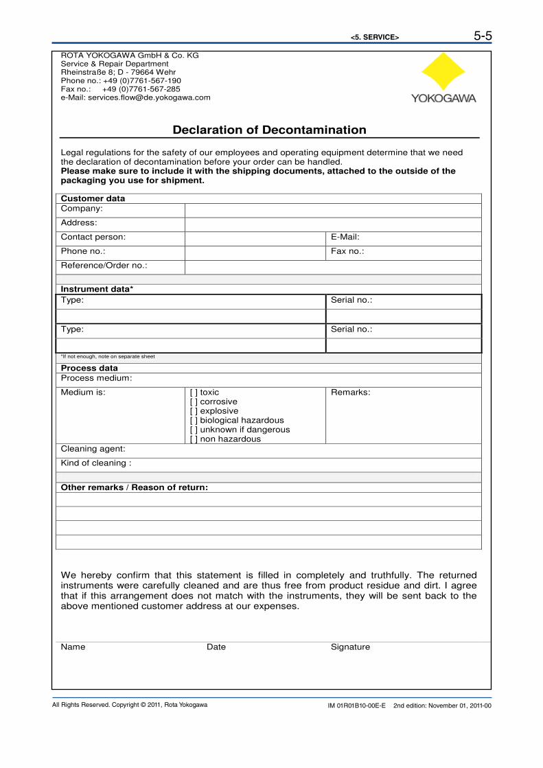
IM 01R01B10-00E-E 2nd edition: November 01, 2011-00All Rights Reserved. Copyright © 2011, Rota Yokogawa
ROTA YOKOGAWA GmbH & Co. KG Service & Repair Department Rheinstraße 8; D - 79664 Wehr Phone no.: +49 (0)7761-567-190 Fax no.: +49 (0)7761-567-285 e-Mail: [email protected]
Declaration of Decontamination Legal regulations for the safety of our employees and operating equipment determine that we need the declaration of decontamination before your order can be handled. Please make sure to include it with the shipping documents, attached to the outside of the packaging you use for shipment.
Customer data
Company:
Address:
Contact person: E-Mail:
Phone no.: Fax no.:
Reference/Order no.:
Instrument data*
Type: Serial no.:
Type: Serial no.:
*If not enough, note on separate sheet
Process data
Process medium:
Medium is: [ ] toxic [ ] corrosive [ ] explosive [ ] biological hazardous [ ] unknown if dangerous [ ] non hazardous
Remarks:
Cleaning agent:
Kind of cleaning :
Other remarks / Reason of return:
We hereby confirm that this statement is filled in completely and truthfully. The returned instruments were carefully cleaned and are thus free from product residue and dirt. I agree that if this arrangement does not match with the instruments, they will be sent back to the above mentioned customer address at our expenses. Name Date Signature
<5. SERVICE>5-6
IM 01R01B10-00E-E 2nd edition: November 01, 2011-00 All Rights Reserved. Copyright © 2011, Rota Yokogawa
Blank Page
<6. EXPLOSION PROTECTED INSTRUMENTS> 6-1
IM 01R01B10-00E-E 2nd edition: November 01, 2011-00All Rights Reserved. Copyright © 2011, Rota Yokogawa
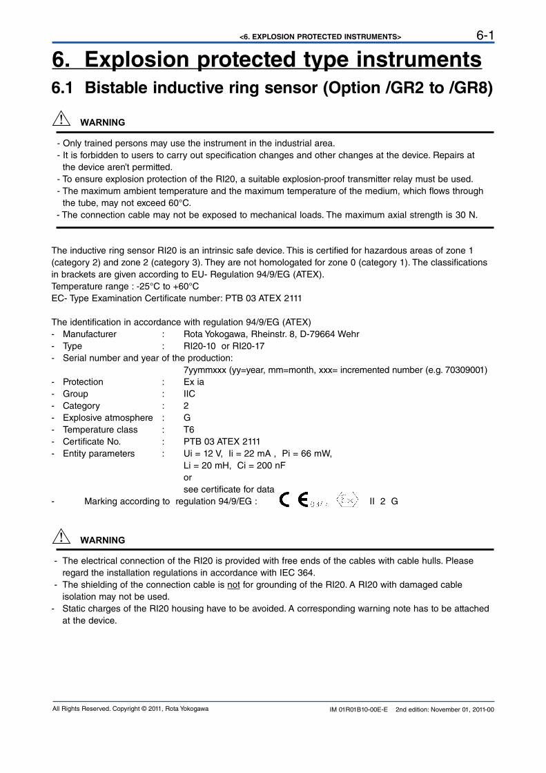
6. Explosion protected type instruments6.1 Bistable inductive ring sensor (Option /GR2 to /GR8)
- Only trained persons may use the instrument in the industrial area. - It is forbidden to users to carry out specification changes and other changes at the device. Repairs at the device aren’t permitted. - To ensure explosion protection of the RI20, a suitable explosion-proof transmitter relay must be used. - The maximum ambient temperature and the maximum temperature of the medium, which flows through the tube, may not exceed 60°C.
- The connection cable may not be exposed to mechanical loads. The maximum axial strength is 30 N.
The inductive ring sensor RI20 is an intrinsic safe device. This is certified for hazardous areas of zone 1 (category 2) and zone 2 (category 3). They are not homologated for zone 0 (category 1). The classifications in brackets are given according to EU- Regulation 94/9/EG (ATEX).Temperature range : -25°C to +60°C EC- Type Examination Certificate number: PTB 03 ATEX 2111
The identification in accordance with regulation 94/9/EG (ATEX)- Manufacturer : Rota Yokogawa, Rheinstr. 8, D-79664 Wehr- Type : RI20-10 or RI20-17- Serial number and year of the production: 7yymmxxx (yy=year, mm=month, xxx= incremented number (e.g. 70309001)- Protection : Ex ia - Group : IIC - Category : 2- Explosive atmosphere : G- Temperature class : T6- Certificate No. : PTB 03 ATEX 2111- Entity parameters : Ui = 12 V, Ii = 22 mA , Pi = 66 mW, Li = 20 mH, Ci = 200 nF or see certificate for data- Marking according to regulation 94/9/EG : II 2 G
- The electrical connection of the RI20 is provided with free ends of the cables with cable hulls. Please regard the installation regulations in accordance with IEC 364. - The shielding of the connection cable is not for grounding of the RI20. A RI20 with damaged cable isolation may not be used.- Static charges of the RI20 housing have to be avoided. A corresponding warning note has to be attached at the device.
WARNING
WARNING
<6. EXPLOSION PROTECTED INSTRUMENTS>6-2
IM 01R01B10-00E-E 2nd edition: November 01, 2011-00 All Rights Reserved. Copyright © 2011, Rota Yokogawa
Installation in Hazardous area:
15
4 631
14
12 10118 79U
Mai
ns /
Net
z / T
ensi
on
One
cha
nnel
tran
smitt
er :
...-S
R2-
Ex1.
W, c
onne
ctio
n lik
e lim
it M
AXEi
nkan
alig
er V
erst
ärke
r : .
..-SR
2-Ex
1.W
, Ans
chlu
ss w
ie G
renz
wer
t MAX
Un
cana
l am
plifi
cate
ur
: ...
-SR
2-Ex
1.W
, rac
cord
com
me
limite
MAX
Tran
smitt
er R
elay
Tren
nsch
altv
erst
ärke
rAm
plifi
cate
ur S
epar
ateu
r
Limit /
Gre
nzwe
rt / L
imite
MIN
Limit /
Gre
nzwe
rt / L
imite
MAX
Max
Min
EN 6
0947
-5-6
(Nam
ur)
Max
imum
med
ium
- and
am
bien
t tem
pera
ture
:M
axim
ale
Med
ium
s- u
nd U
mge
bung
stem
pera
tur :
Tem
pera
ture
am
bian
te e
t tem
pera
ture
de
fluid
e m
axim
ale
:
Tam
ax =
60°
C
-+-+
~~
+ - + -
Ci
= 20
0nF
Ex i
a IIC
T6
Li =
20m
H
RI2
0-10
, R
I20-
17
Pi =
66m
WIi
= 2
2mA
Ui
= 12
V
PTB
03 A
TEX
2111
C =
232
0nF
I =
19,
1mA
P =
51m
W
U =
10.
6V
L =
97m
HPT
B 00
ATEX
208
1
EEx
ia /
ib I
ICKF
A6-S
R2-
Ex2.
W
oo oo o
C =
241
0nF
I =
13m
AP
= 3
4mW
U =
10.
5V
L =
210
mH
PTB
00AT
EX 2
080
EEx
ia /
ib I
ICKF
D2-
SR2-
Ex2.
W
oo oo o
Haz
ardo
us A
rea
Ex- B
erei
chZo
ne E
x
Safe
Are
aSi
cher
er B
erei
chH
ors
Zone
Optio
n /W
4B 2
4VDC
KFD2
-SR2
-Ex2
.WOp
tion /
W2B
230
VAC
KFA6
-SR2
-Ex2
.WInd
uctiv
e ring
sens
or R
I20Ind
uktiv
er R
ingini
tiator
RI20
Bagu
e ind
uctiv
e RI20
Rotam
eter R
AGN
optio
n /GR
x (x =
2 ...
8)
F2.E
PS
<6. EXPLOSION PROTECTED INSTRUMENTS> 6-3
IM 01R01B10-00E-E 2nd edition: November 01, 2011-00All Rights Reserved. Copyright © 2011, Rota Yokogawa
Marking:
6.2 Magnetic contact (Option /GM1 to /GM5)
• Only trained persons may use the instrument in the industrial area. • It is forbidden to users to carry out specification changes and other changes at the device. Repairs at
the device aren’t permitted. • To ensure explosion protection of the GM, a suitable explosion-proof transformer isolated barrier must
be used. • The maximum ambient temperature and the maximum temperature of the medium, which flows through
the tube, may not exceed 70°C.
• The connection cable may not be exposed to mechanical loads. The maximum axial strength is 30 N.
• Static charge of the GM case has to be avoided. A corresponding warning note has to be attached at
the device.
The limit switch GM is classified according EN 60079-11 chapter 5.7, IEC 60079-11 chapter 5.7 and ANSI/ISA 60079-11 chapter 5.7 as "Simple Apparatus".For use in hazardous area the limit switch must be connected to a suitable explosion-proof transformer isolated barrier, which does not exceed the following maximum values :Maximum voltage Uo : 15 VMaximum current Io : 50 mAMaximum power Po : 187 mW
Classification :
- Type : GM1 or GM2
- Protection : intrinsic safe
- ATEX / IECEx : IIC 2G
- FM : I, 1, A, B, C, D
- Temperature class : T6
- Entity parameters : Ui = 15 V ; Ii = 50 mA ; Pi = 187 mW ; Li ≈ 0 mH ; Ci ≈ 0 nF
WARNING
Rota YokogawRheinstr. 8D-79664 WehrType : RI20-10-KU = 4.5 ... 15VSN : ..............
Rota YokogawaRheinstr. 8D-79664 WehrType : RI20-10-KU = 4.5 ... 15VSN : ..............
Ex ia IIC T6PTB 03 ATEX 2111
II 2 Gsee certificatefor data
<6. EXPLOSION PROTECTED INSTRUMENTS>6-4
IM 01R01B10-00E-E 2nd edition: November 01, 2011-00 All Rights Reserved. Copyright © 2011, Rota Yokogawa
Installation in Hazardous area:
F3.E
PS
EX -
BERE
ICH
HAZA
RDO
US A
REA
ZONE
EX
GRE
NZW
ERTS
CHAL
TER
GM
LIM
IT S
WIT
CH G
MCO
NTAC
T LI
MIT
E G
M
ROTA
MET
ER R
AGN
with
opt
ion
/GM
x (x
= 1
... 5
)
MAX
IMAL
E M
EDIU
MS
UND
UMG
EBUN
GST
EMPE
RATU
RM
AXIM
UM M
EDIU
M A
ND A
MBI
ENT
TEM
PERA
TURE
TEM
PERA
TURE
AM
BIAN
TE E
T TE
MPE
RATU
RE D
E FL
UIDE
MAX
IMAL
ET
=
70°
C a
max
EN 6
0947
-5-6
(NAM
UR)
GM
1, G
M2
Ex II
C T6
I
= 50
mA
max
max
U
= 15
V
L
= 0m
HT
=
70°C
C
= 0n
F
P
= 18
7mW
am
ax
max
ACHT
UNG
! ATT
ENTI
ON!
ATT
ENTI
ON!
DIES
E KO
NFIG
URAT
ION
IST
NUR
IN Z
ONE
1 U
ND 2
EI
NSET
ZBAR
THIS
CO
NFIG
URAT
ION
IS O
NLY
FOR
ZONE
1 A
ND 2
SICH
ERER
BER
EICH
SAFE
ARE
A
HORS
ZO
NE
NETZ
/ M
AINS
/ TE
NSIO
N
OPT
ION:
/W4B
24V
DCKF
D2-S
R2-E
x.W
OPT
ION:
/W2B
230
VAC
KFA6
-SR2
-Ex.
W
9 8 1 1 17
11
1 3 4 6
+ - + -
GRE
NZW
ERT
/ LIM
IT /
LIM
ITE
MA
X
GRE
NZW
ERT
/ LIM
IT /
LIM
ITE
MIN
TREN
NSCH
ALTV
ERST
ÄRKE
RTR
ANSF
ORM
ER IS
OLA
TED
BARR
IER
AMPL
IFIC
ATEU
R SE
PARA
TEUR
T
= 60
°CL
=
210m
HC
=
2410
nF
P
= 34
mW
I
= 13
mA
(EEx
ib) I
IC
KFD2
-SR2
-Ex2
.W
U
= 10
,5V
am
ax
o
o o
o
o
T
= 60
°CL
=
97m
HC
=
2320
nF
P
= 51
mW
I
= 19
.1m
AU
=
10,6
V(E
Ex ib
) IIC
am
ax
o
o
o o
o
KFA6
-SR2
-Ex2
.W
(L+
(L-)
PTB
00 A
TEX
2080
PTB
00 A
TEX
2081
EINK
ANAL
IGE
VERS
TÄRK
ER ..
.....-
SR2-
EX1.
W A
NSCH
LUSS
WIE
GRE
NZW
ERT
"MAX
"O
NE C
HANN
EL T
RANS
MIT
TER
.....-
SR2-
EX1.
W C
ONN
ECTI
ON
LIKE
LIM
IT "M
AX"
UN C
ANAL
AM
PLIF
ICAT
EUR
......
..-SR
2-EX
1.W
RAC
CORD
CO
MM
E LI
MIT
E "M
AX"
<7. INSTRUCTIONS FOR PED> 7-1
IM 01R01B10-00E-E 2nd edition: November 01, 2011-00All Rights Reserved. Copyright © 2011, Rota Yokogawa
The meters RAGN 04-..., RAGN05-... and RAGN06-... are produced according the determinations of directive 97/23/EG (directive for Pressure – Equipment / PED ).
The units are classified as pipe according item 3, number 1, 3. letter, a) first dash or according diagram 6 after appendix II :
- Classification as pipe- For Fluid Group 1 (article 9 chapter (2)). - Medium fluid and gas
The basic safety requests (for design, production and testing) for all units according to category I are generally determined for the requests of category I.
The units, which are not excluded by PED article 3 paragraph 3, are checked by a conformity-valuation-method according appendix III ´module A´.
The user is responsible for the use of our flowmeters regarding suitability and use as agreed.
7. Instructions for PED
IMPORTANT
<7. INSTRUCTIONS FOR PED>7-2
IM 01R01B10-00E-E 2nd edition: November 01, 2011-00 All Rights Reserved. Copyright © 2011, Rota Yokogawa
Blank Page

<8. TECHNICAL DATA> 8-1
IM 01R01B10-00E-E 2nd edition: November 01, 2011-00All Rights Reserved. Copyright © 2011, Rota Yokogawa
8. Technical Data OPTION SPECIFICATIONSLimit switch (option /GM1 to /GM5):( for P- tubes with PVDF- or SS- float with magnet only) Type : reed contact with bistable switching Max. switching voltage : 230 V Max. switching current : 2 A Max. switching capacity : 40 W/VA Temperature range : -10°C to +70°C Protection : IP65 Internal capacity : 0 nF Internal inductivity : 0 mH Electrical connection : LIYY 2 x 0.34 mm²; length 1 m Housing : Polystyrene Weight : 35 g Explosion proof : Intrinsic safe acc. EN 60079-11 chapter 5.7, IEC 60079-11 chapter 5.7 and ANSI/ISA 60079-11 chapter 5.7 as "Simple Apparatus". Group : IIC Category : 2G Temperature class : T6 Entity parameter : Ui = 15 V ; Ii = 50 mA ; Pi = 187 mW Li ≈ 0 mH ; Ci ≈ 0 nF
Limit switch (option /GR2 to /GR8):(for L- tubes with PVDF float only) Type : Bistable inductive ring sensor Power supply : 4.5 V to 15 V DC Consumption : acc. DIN EN 60947-5-6 (NAMUR) Float below ring sensor : < 1 mA Float above ring sensor : > 2.2 mA Temperature range : -25°C to +65°C non-Ex- type Protection : IP 67 Electrical connection : 2 x 0.14 mm² , with shield 0.4 mm², 2 m long Explosion proof type (option /KS1): Temperature range : -25°C to +60°C Marking acc. guideline 94/9/EG : Manufacturer : Rota Yokogawa, Rheinstr.8, D-79664 Wehr Type : RI20-10K/G or RI20-17K/G Year of production : in serial number Protection : Ex ia Group : IIC Category : 2G Temperature class : T6 Certificate No. : PTB 03ATEX 2111 Safety relevant data (see also certificate for data): Ui = 12 V, Ii = 22 mA , Pi = 66 mW, Li = 20 mH, Ci = 200 nF
CE-marking : II 2 G
Power supply for limit switch (option /W__): Type : acc. DIN EN 60947-5-6 (NAMUR) - KFA5-SR2-Ex*-W (115 V AC), * = 1 or 2 - KFA6-SR2-Ex*-W (230 V AC), * = 1 or 2 - KFD2-SR2-Ex*-W (24 V DC), * = 1 or 2 - KHA6-SH-Ex1 (115/230 V AC), Fail Safe, 1 channel - KFD2-SH-Ex1 (24 V DC), Fail Safe, 1 channel Power supply : - 230 V AC ± 10%, 45-65Hz - 115 V AC ± 10%, 45-65Hz - 24 V DC ± 25% Relay output : 1 or 2 potential-free changeover contact(s) Switching capacity : max. 250 V AC, max. 2 A
STANDARD SPECIFICATIONSFluids to be measured : Liquids and gas
Measurable flow rates : - Water (20 °C) : 0.002 l/h to 10 m3/h - Air (20 °C; 1 bar abs.) : 0.1 l/h to 160 m3/h
Turndown : - P metering tube : 10:1 - L metering tube : 20:1
Metering tubes : L6; L7; P0; P1; P2; P4 (length 300 mm)
Process temperature : -25°C to +100°C
Process pressure :
Metering tube L6;L7 P0;P1 P2 P4
Pmax (bar) 16 10 8 6
Installation length :
Process connection Thread Clamp Flange
Length [mm] 375 375 425 Weight : Depending on design (see page 7)
Accuracy :
Tube Measuring accuracy acc. Directive VDI/VDE 3513 sheet 2 (qG= 50%)
L613 - L623 2.5%
L624 - L747 1.6%
P051 - P471 1.6%
Materials : Threads G, NPT : AISI 316L (1.4404) Flange EN / ASME : AISI 316L (1.4404) Clamp ISO 2852 : AISI 316L (1.4404) Housing : AISI 304 (1.4301) Nut : AISI 316 (1.4401) (or galvanized steel) Stoppers (L6, L7 tube) : PFA Stoppers (P0 - P4 tube) : PVDF, AISI 316L (1.4404) Measuring cone : Borosilicate glass Float (L6, L7 tube ) : Titanium, PVDF Float (P0 - P4 tube) : PTFE, PVDF (FDA conform), AISI 316Ti (1.4571) Gaskets : NBR, FKM,EPDM (FDA conform)
Pressure Equipment Directive (PED) Directive 97/23/EG: Models : RAGN04, RAGN05, RAGN06 Tubes : - Modul : A - Fluid Group : 1 (liquid, gases) - Produced acc. to category : I
FDA-Conformity: RAGN with P- tube, PVDF- or SS- float and EPDM- gaskets (option /ME). Stoppers and floats made of PVDF: 21 CFR § 177 2510(a) O-rings made of EPDM: 21 CFR § 177 2600-21
Compliance with safety application acc. IEC 61508: 2010 and ISO 13849: Please refer to the FMEDA report and instruction manual.
<8. TECHNICAL DATA>8-2
IM 01R01B10-00E-E 2nd edition: November 01, 2011-00 All Rights Reserved. Copyright © 2011, Rota Yokogawa
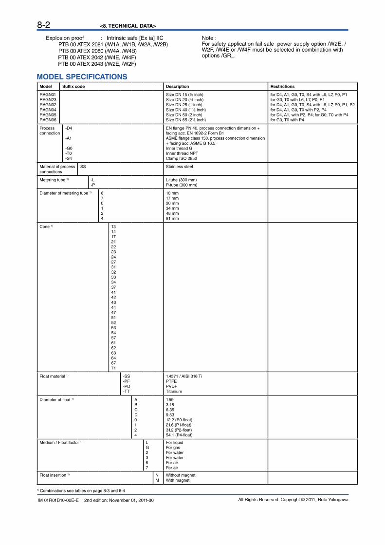
MODEL SPECIFICATIONSModel Suffix code Description Restrictions
RAGN01RAGN23RAGN02RAGN04RAGN05RAGN06
Size DN 15 (½ inch)Size DN 20 (¾ inch)Size DN 25 (1 inch)Size DN 40 (1½ inch)Size DN 50 (2 inch)Size DN 65 (2½ inch)
for D4, A1, G0, T0, S4 with L6, L7, P0, P1for G0, T0 with L6, L7, P0, P1for D4, A1, G0, T0, S4 with L6, L7, P0, P1, P2for D4, A1, G0, T0 with P2, P4for D4, A1, with P2, P4; for G0, T0 with P4for G0, T0 with P4
Process connection
-D4
-A1
-G0-T0-S4
EN flange PN 40, process connection dimension + facing acc. EN 1092-2 Form B1ASME flange class 150, process connection dimension + facing acc. ASME B 16.5Inner thread GInner thread NPTClamp ISO 2852
Material of process connections
SS Stainless steel
Metering tube 1) -L-P
L-tube (300 mm)P-tube (300 mm)
Diameter of metering tube 1) 670124
10 mm17 mm20 mm34 mm48 mm81 mm
Cone 1) 1314172122232427313233343741424344475152535457616263646771
Float material 1) -SS-PF-PD-TT
1.4571 / AISI 316 TiPTFEPVDFTitanium
Diameter of float 1) ABCD0124
1.593.186.359.5312.2 (P0-float)21.6 (P1-float)31.2 (P2-float)54.1 (P4-float)
Medium / Float factor 1) LG2367
For liquidFor gasFor waterFor waterFor airFor air
Float insertion 1) NM
Without magnetWith magnet
1) Combinations see tables on page 8-3 and 8-4
Explosion proof : Intrinsic safe [Ex ia] IIC PTB 00 ATEX 2081 (/W1A, /W1B, /W2A, /W2B) PTB 00 ATEX 2080 (/W4A, /W4B) PTB 00 ATEX 2042 (/W4E, /W4F) PTB 00 ATEX 2043 (/W2E, /W2F)
Note :For safety application fail safe power supply option /W2E, /W2F, /W4E or /W4F must be selected in combination with options /GR_.
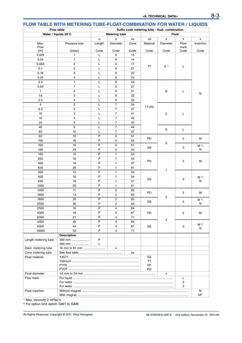
<8. TECHNICAL DATA> 8-3
IM 01R01B10-00E-E 2nd edition: November 01, 2011-00All Rights Reserved. Copyright © 2011, Rota Yokogawa
FLOW TABLE WITH METERING TUBE-FLOAT-COMBINATION FOR WATER / LIQUIDSFlow table Suffix code metering tube - float- combination
Water / liquids 20°C Metering tube Float
-x x xx -xx x x x
Max.Flow[l/h]
Pressure loss
[mbar]
Length
Code
Diameter
Code
Cone
Code
Material
Code
Diameter
Code
Flow markCode
Insertion
Code0.025 1 L 6 13
TT A 1) L
N
0.04 1 L 6 14
0.063 2 L 6 17
0.1 2 L 6 21
0.16 3 L 6 22
0.25 4 L 6 23
0.4 1 L 6 24
TT;PD
B L
0.63 1 L 6 27
1 2 L 6 31
1.6 3 L 6 32
2.5 4 L 6 33
4 2 L 7 34
C L
6.3 2 L 7 37
10 3 L 7 41
16 4 L 7 42
25 5 L 7 43
40 5 L 7 44D L
63 10 L 7 47
63 10 P 0 51PD
0
2 M100 16 P 0 52
100 16 P 0 51SS 3
M 2);N160 24 P 0 52
160 15 P 1 53
PD
1
2 M250 16 P 1 54
400 18 P 1 57
630 26 P 1 61
250 15 P 1 53
SS 3M 2);
N400 16 P 1 54
630 18 P 1 57
1000 26 P 1 61
1000 11 P 2 62PD
2
2 M1600 13 P 2 63
1600 26 P 2 62SS 3
M 2);N2500 30 P 2 63
2500 16 P 4 64
PD
4
2 M4000 18 P 4 67
6300 21 P 4 71
4000 40 P 4 64
SS 3M 2);
N6300 44 P 4 67
10000 53 P 4 71
DescriptionLength metering tube 300 mm .....................
300 mm ..................... PL
Diam. metering tube 10 mm to 81 mm .......................... x
Cone metering tube See flow table .................................................. xx
Float material 1.4571 ..................................................................................Titanium ...............................................................................PTFE ....................................................................................PVDF ...................................................................................
SSTTPFPD
Float diameter 1.6 mm to 54 mm .................................................................................... x
Flow mark For liquid .....................................................................................................................For water ......................................................................................................................For water ......................................................................................................................
L23
Float insertion Without magnet ..............................................................................................................................With magnet ...................................................................................................................................
NM2)
1) Max. viscosity 2 mPas*s2) For option limit switch /GM1 to /GM5
<8. TECHNICAL DATA>8-4
IM 01R01B10-00E-E 2nd edition: November 01, 2011-00 All Rights Reserved. Copyright © 2011, Rota Yokogawa
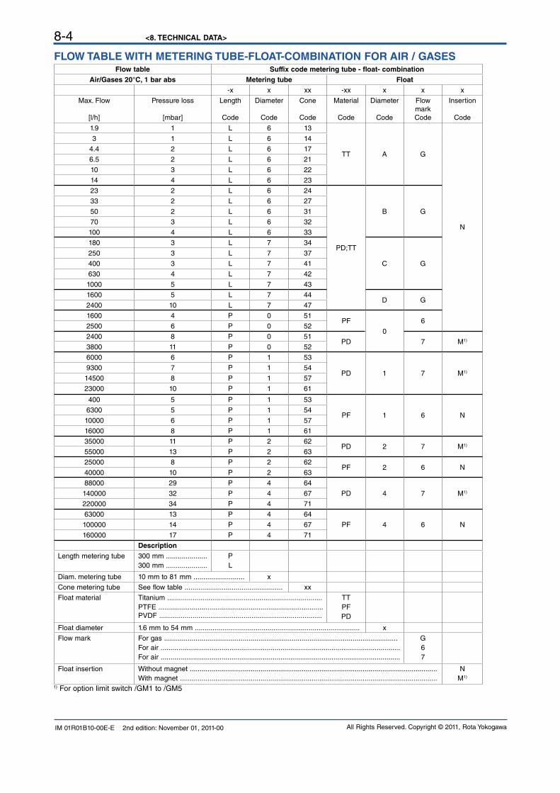
FLOW TABLE WITH METERING TUBE-FLOAT-COMBINATION FOR AIR / GASESFlow table Suffix code metering tube - float- combination
Air/Gases 20°C, 1 bar abs Metering tube Float-x x xx -xx x x x
Max. Flow
[l/h]
Pressure loss
[mbar]
Length
Code
Diameter
Code
Cone
Code
Material
Code
Diameter
Code
Flow markCode
Insertion
Code
1.9 1 L 6 13
TT A G
N
3 1 L 6 14
4.4 2 L 6 17
6.5 2 L 6 21
10 3 L 6 22
14 4 L 6 23
23 2 L 6 24
PD;TT
B G
33 2 L 6 27
50 2 L 6 31
70 3 L 6 32
100 4 L 6 33
180 3 L 7 34
C G
250 3 L 7 37
400 3 L 7 41
630 4 L 7 42
1000 5 L 7 43
1600 5 L 7 44D G
2400 10 L 7 47
1600 4 P 0 51PF
0
62500 6 P 0 52
2400 8 P 0 51PD 7 M1)
3800 11 P 0 52
6000 6 P 1 53
PD 1 7 M1)9300 7 P 1 54
14500 8 P 1 57
23000 10 P 1 61
400 5 P 1 53
PF 1 6 N6300 5 P 1 54
10000 6 P 1 57
16000 8 P 1 61
35000 11 P 2 62PD 2 7 M1)
55000 13 P 2 63
25000 8 P 2 62PF 2 6 N
40000 10 P 2 63
88000 29 P 4 64
PD 4 7 M1)140000 32 P 4 67
220000 34 P 4 71
63000 13 P 4 64
PF 4 6 N100000 14 P 4 67
160000 17 P 4 71
DescriptionLength metering tube 300 mm .....................
300 mm ..................... PL
Diam. metering tube 10 mm to 81 mm .......................... x
Cone metering tube See flow table .................................................. xx
Float material Titanium ...............................................................................PTFE ....................................................................................PVDF ...................................................................................
TTPFPD
Float diameter 1.6 mm to 54 mm .................................................................................... x
Flow mark For gas .......................................................................................................................For air ..........................................................................................................................For air ..........................................................................................................................
G67
Float insertion Without magnet ..............................................................................................................................With magnet ...................................................................................................................................
NM1)
1) For option limit switch /GM1 to /GM5
<8. TECHNICAL DATA> 8-5
IM 01R01B10-00E-E 2nd edition: November 01, 2011-00All Rights Reserved. Copyright © 2011, Rota Yokogawa
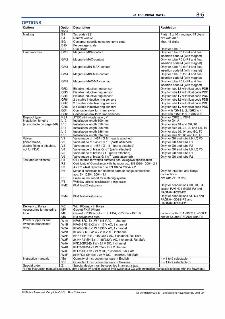
OPTIONS Options Option
CodeDescription Restriction
Marking /B1/B4/BG/B10/BD
Tag plate (SS) Neutral versionCustomer specific notes on name platePercentage scaleDual scale
Plate 12 x 40 mm; max. 45 digitsNot with /KS1Max. 45 digits
Only for tube PLimit switches /GM1
/GM2
/GM3
/GM4
/GM5
/GR2/GR3/GR4/GR6/GR7/GR8/GD1/GD2
Magnetic MIN-contact
Magnetic MAX-contact
Magnetic MIN-MAX-contact
Magnetic MIN-MIN-contact
Magnetic MAX-MAX-contact
Bistable inductive ring sensorBistable inductive ring sensorBistable inductive ring sensor2 bistable inductive ring sensors 2 bistable inductive ring sensors2 bistable inductive ring sensorsConnection box for 1 limit switch Connection box for 2 limit switches
Only for tube P0 to P4 and float insertion code M (with magnet)Only for tube P0 to P4 and float insertion code M (with magnet)Only for tube P0 to P4 and float insertion code M (with magnet)Only for tube P0 to P4 and float insertion code M (with magnet)Only for tube P0 to P4 and float insertion code M (with magnet)Only for tube L6 with float code PDBOnly for tube L7 with float code PDCOnly for tube L7 with float code PDDOnly for tube L6 with float code PDBOnly for tube L7 with float code PDCOnly for tube L7 with float code PDD Only with /GM1 to 2, /GR2 to 4 Only with /GM3 to 5, /GR6 to 8
Ex-proof type /KS1 ATEX intrinsically safe „ia“ Only for /GR2 to /GR8Installation lengths(s. also table on page 8-6)
/L12/L13/L14/L15/L16
Installation length 500 mmInstallation length 356 mmInstallation length 368 mmInstallation length 386 mmInstallation length 394 mm
Only for D4, A1Only for size 01 and G0, T0Only for size 01, 23, 02 and G0, T0Only for size 02, 04 and G0, T0Only for size 05, 06 and G0, T0
Valves(inner thread, double fitting is attached,not for FDA)
/V1/V2/V3/V4/V5/V6
Valve made of 1.4571 G ½´´ (parts attached)Valve made of 1.4571 G 1´´ (parts attached)Valve made of 1.4571 G 1½´´ (parts attached)Valve made of brass G ½´´ (parts attached)Valve made of brass G 1´´ (parts attached)Valve made of brass G 1½´´ (parts attached)
Only for G0 and tube L6, L7, P0Only for G0 and tube P1Only for G0 and tube P2Only for G0 and tube L6, L7, P0Only for G0 and tube P1Only for G0 and tube P2
Test and certificates /H1/P2/P3/P6
/PP/PT/PM2
/PM4
Oil + fat free for wetted surfaces acc. Yokogawa specificationCertificate of Compliance with the order acc. EN 10204: 2004- 2.1As /P2 +Test report acc. to EN 10204: 2004- 2.2 Material certificate for Insertion parts or flange connectionsacc. EN 10204: 2004- 3.1Pressure test report for metering systemWith flow table for recalculation + mm- scalePAMI test (2 test points)
PAMI test (4 test points)
Only for insertion and flange connectionsNot with /V1 to /V6
Only for connections G0, T0, S4 except RAGN04-G0SS-P2 and RAGN04-T0SS-P2Only for connections A1, D4 andRAGN04-G0SS-P2 andRAGN04-T0SS-P2
Delivery to Korea /KC With KC-mark in KoreaAccessories for metering tube
/MV/ME/MN
Gasket FKM (Viton) Gasket EPDM (conform to FDA, -30°C to +100°C)Nut galvanized steel
conform with FDA -30°C to +100°Cnot for S4 and RAGN04 with P2
Power supply for limit switches (transmitter relay)
/W1A/W1B/W2A/W2B/W2E/W2F/W4A/W4B/W4E/W4F
KFA5-SR2-Ex1.W / 115 V AC, 1 channelKFA5-SR2-Ex2.W / 115 V AC, 2 channelKFA6-SR2-Ex1.W / 230 V AC, 1 channelKFA6-SR2-Ex2.W / 230 V AC, 2 channelKHA6-SH-Ex1 / 115/230 V AC, 1 channel, Fail Safe2x KHA6-SH-Ex1 / 115/230 V AC, 1 channel, Fail SafeKFD2-SR2-Ex1.W / 24 V DC, 1 channelKFD2-SR2-Ex2.W / 24 V DC, 2 channelKFD2-SH-Ex1 / 24 V DC, 1 channel, Fail Safe2x KFD2-SH-Ex1 / 24 V DC, 1 channel, Fail Safe
Instruction manuals /IEn/IDn
Quantity of instruction manuals in EnglishQuantity of instruction manuals in German
n = 1 to 9 selectable *)n = 1 to 9 selectable *)
Special order /Z Special design must be specified in an extra text.*) If no instruction manual is selected, only a Short IM and in case of limit switches a CD with instruction manuals is shipped with the flowmeter.

<8. TECHNICAL DATA>8-6
IM 01R01B10-00E-E 2nd edition: November 01, 2011-00 All Rights Reserved. Copyright © 2011, Rota Yokogawa
DIMENSIONS METERING TUBE
12
4
6
8
0101
6
21
4
8
10
6
21
4
8
LLL
Inner thread type (T0; G0) Clamp type (S4) Flange type (D4; A1)
Installation lengths and weights:
Model Process connection
Tube Length Lmm
Weightkg
RAGN01
Inner thread
L6; L7; P0; P1
375 1.7
Clamp 375 1.9
Flange 425 2.5
RAGN23 Inner thread 375 1.7
RAGN02
Inner threadL6; L7; P0; P1
375
1.7
P2 2.6
ClampL6; L7; P0; P1 2.0
P2 2.8
FlangeL6; L7; P0; P1
4253.3
P2 3.9
RAGN04
Inner threadP2
3752.6
P4 7.1
FlangeP2
4255.2
P4 8.7
RAGN05
Inner thread P4 375 7.1
FlangeP2
4256.6
P4 11.1
RAGN06 Inner thread P4 375 7. 7.1 1
Compatibility with former Rotameter RAGG / RAGH:
Former model Tube Installation length mm
Model RAGN
RAGH01 L6;L7;G0 356 RAGN01..../L13
RAGH02 G1 368 RAGN02..../L14
RAGH04 G2 386 RAGN04..../L15
RAGH06 G4 394 RAGN06..../L16
RAGH23 G1 368 RAGN23..../L14
RAGH05 G4 394 RAGN05..../L16
RAGG01 G0;G1 500 RAGN01..../L12
RAGG02 G2 500 RAGN02..../L12
RAGG04 G4 500 RAGN04..../L12
PROCEDURE TO SELECT THE MODEL CODEPlease specify in the following order- Measuring range for water/liquid or air/gas- With or without optional limit switchFirst select the required measuring range from the flow table (last column) and specify the float insertion for the optional limit switch. Then the suffix code for the combination metering tube - float can be fixed.To size the Rotameter for other medium - process- conditions use sizing program Durep V.
<8. TECHNICAL DATA> 8-7
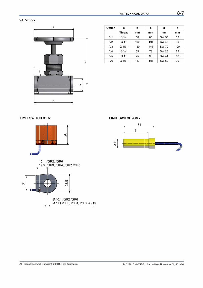
IM 01R01B10-00E-E 2nd edition: November 01, 2011-00All Rights Reserved. Copyright © 2011, Rota Yokogawa
e
d
b
c
a
VALVE /Vx
LIMIT SWITCH /GRx LIMIT SWITCH /GMx
21 25.5
26
16 /GR2, /GR619.5 /GR3, /GR4, /GR7, /GR8
Ø 10.1 /GR2 /GR6Ø 17.1 /GR3, /GR4, /GR7, /GR8
Ø14
41
51
Option a b c d e
Thread mm mm mm mm
/V1 G ½´´ 60 88 SW 30 63
/V2 G 1´´ 100 110 SW 45 90
/V3 G 1½´´ 130 145 SW 70 100
/V4 G ½´´ 55 78 SW 25 63
/V5 G 1´´ 75 93 SW 41 63
/V6 G 1½´´ 110 118 SW 60 90

<8. TECHNICAL DATA>8-8
IM 01R01B10-00E-E 2nd edition: November 01, 2011-00 All Rights Reserved. Copyright © 2011, Rota Yokogawa
Blank Page

<A1. SAFETY INSTRUMENTED SYSTEMS INSTALLATION> A1-1
IM 01R01B10-00E-E 2nd edition: November 01, 2011-00All Rights Reserved. Copyright © 2011, Rota Yokogawa
The contents of this appendix are cited from exida.com safety manual on the Rotameter RAGN Flowmeter specifically observed for the safety transmitter purpose. When using the RAGN for Safety Instrumented Systems (SIS) application, the instructions and procedures in this section must be strictly followed in order to preserve the meter for that safety level.
A1.1 Scope and PurposeThis document provides an overview of the user responsibilities for installation and operation of the Rota Yokogawa RAGN variable area flow meter, herein referred to as RAGN Glass Rotameter, in order to maintain the designed safety level. Items that will be addressed are proof testing, repair and replacement of the flow meter, reliability data, lifetime, environmental and application limits, and parameter settings.
A1.2 Using RAGN for a SIS Application
A1.2.1 Safety Function
Suitable for use in Safety Instrumented Systems are the versions listed in table 1 only. The safety related data listed in this manual does not apply to other versions of RAGN.Table 1 Versions of RAGN suitable for Safety Instrumented Systems
[V1] RAGN with Reed-switch(es)
[V2] RAGN with Ring Initiator, fail-safe state: LOW
[V3] RAGN with Ring Initiator, fail-safe state: HIGH
This variable area flow meter is intended for use as a volume flow monitoring component in a Safety Instrumented System. It has either inductive ring sensors [V2], [V3] or magnetic reed contacts [V1] to indicate limits. The flow meter may be used with the limit switches to feed signals to a logic solver that is part of the safety instrumented function (SIF) as shown in Figure 1. The fault annunciation mechanism is a trip of one of the limit switches. In order to take credit for the automatic diagnostics in the flow meter, this annunciation mechanism must be connected.Any valve delivered together with RAGN Glass Rotameter is not covered by the assessment.
Figure 1 Example Safety Instrumented Function
APPENDIX 1. Safety Instrumented Systems Installation
WARNING
<A1. SAFETY INSTRUMENTED SYSTEMS INSTALLATION>A1-2
IM 01R01B10-00E-E 2nd edition: November 01, 2011-00 All Rights Reserved. Copyright © 2011, Rota Yokogawa
A1.2.2 Diagnostic Response Time
There is neither diagnostic in the magnetic reed contacts [V1] nor in the inductive ring sensors [V2], [V3].
A1.2.3 Setup
A setup of the flow meter is not required. Installation shall be done according to the manual.Precautions for use of ring sensors [V2], [V3] in Safety Instrumented Functions:The high output current should be used as the preferred “safe state”. Therefore to achieve highest reliability of the system, the orientation of the ring sensors should be set according to the application to set high current as safe state. For more information on assembly see User’s Manual, Model RAGN Glass Rotameter, IM 01R01B10-00E-E.
A1.2.4 Proof Testing
The objective of proof testing is to detect failures within the flow meter. Of main concern are undetected failures that prevent the safety instrumented function from performing its intended function.The frequency of the proof tests (or the proof test interval) is to be determined in the reliability calculations for the safety instrumented functions for which the flow meter is applied. The actual proof tests must be performed more frequently or as frequently as specified in the calculation in order to maintain required safety integrity of the safety instrumented function.The following tests need to be specifically executed when a proof test is performed. The results of the proof test need to be documented and this documentation should be part of a plant safety management system. Failures that are detected should be reported to Yokogawa.
Proof test for RAGN Glass Rotameter with magnetic contacts and inductive ring sensors:
Step Action
1 Take appropriate action to avoid a false trip
2 Inspect the device for any visible damage, corrosion or contamination.
3a Force the RAGN Glass Rotameter to reach a defined “MAX” threshold value and verify that the magnetic contact or inductive ring initiator goes into the safe state.Note: only applicable if RAGN is equipped with a “MAX” contact.
3b Force the RAGN Glass Rotameter to reach a defined “MIN” threshold value and verify that the magnetic contact or inductive ring initiator goes into the safe state.Note: only applicable if RAGN is equipped with a “MIN” contact.
4 Restore the loop to full operation
5 Restore normal operation
When all the tests listed above are executed a proof test coverage of approximately 99% of possible DU failures in the RAGN Glass Rotameter can be claimed.The following tools need to be available to perform proof testing:Measurement instrument to verify output status of the magnetic reed contacts [V1] or inductive ring sensors [V2], [V3]
The person(s) performing the proof test of the Yokogawa RAGN Glass Rotameter should be trained in SIS operations including bypass procedures, flow meter maintenance and company management of change procedures.
A1.2.5 Repair and replacement
Maintenance information can be found in section Service of the User’s Manual, Model RAGN Glass Rotameter, IM 01R01B10-00E-E.If repair is to be performed with the process online the Rota Yokogawa RAGN Glass Rotameter will need to be bypassed during the repair. The user should setup appropriate bypass procedures for that.Contact the Yokogawa sales office if this instrument requires repairThe person(s) performing the repair and / or replacement of the Rota Yokogawa RAGN Glass Rotameter should have a sufficient skill level.

<A1. SAFETY INSTRUMENTED SYSTEMS INSTALLATION> A1-3
IM 01R01B10-00E-E 2nd edition: November 01, 2011-00All Rights Reserved. Copyright © 2011, Rota Yokogawa
A1.2.6 Startup Time
The flow meter will generate a valid signal within 0.5 seconds of power-on startup.
A1.2.7 Reliability data
A detailed Failure Mode, Effects, and Diagnostics Analysis (FMEDA) report is available from Rota Yokogawa with all failure rates and failure modes. Rota Yokogawa RAGN Glass Rotameter is intended for use in a Low Demand Mode. Low Demand Mode means the average interval between dangerous conditions occurs infrequently.
The Rota Yokogawa RAGN Glass Rotameter is certified up to SIL1 for use in a simplex (1oo1) configuration, depending on the PFDAVG calculation of the entire Safety Instrumented Function.
A1.2.8 Lifetime limits
The expected lifetime of the Yokogawa Rota Yokogawa RAGN Glass Rotameter is 10 years. The reliability data listed in A1.2.7 is only valid for this period. The failure rates of the Rota Yokogawa RAGN Glass Rotameter may increase sometime after this period. Reliability calculations based on the data listed in A1.2.7 for Rota Yokogawa RAGN Glass Rotameter lifetimes beyond 10 years may yield results that are too optimistic, i.e. the calculated Safety Integrity Level will not be achieved.
A1.2.9 Environmental limits
The environmental limits of Rota Yokogawa RAGN variable area flow meter are specified in the User’s Manual, Model RAGN Glass Rotameter, IM 01R01B10-00E-E.
A1.2.10 Application limits
The application limits of the Rota Yokogawa RAGN variable area flow meter are specified in the User’s Manual, Model RAGN Glass Rotameter, IM 01R01B10-00E-E. If the flow meter is used outside of the application limits the reliability data listed in A1.2.7 becomes invalid.
<A1. SAFETY INSTRUMENTED SYSTEMS INSTALLATION>A1-4
IM 01R01B10-00E-E 2nd edition: November 01, 2011-00 All Rights Reserved. Copyright © 2011, Rota Yokogawa
A1.3 Definitions and Abbreviations
A1.3.1 Definitions
Safety Freedom from unacceptable risk of harm
Functional Safety The ability of a system to carry out the actions necessary to achieve or to maintain a defined safe state for the equipment / machinery / plant / apparatus under control of the system.
Basic Safety The equipment must be designed and manufactured such that it protects against risk of damage to persons by electrical shock and other hazards and against resulting fire and explosion. The protection must be effective under all conditions of the nominal operation and under single fault condition.
Verification The demonstration for each phase of the life-cycle that the (output) deliverables of the phase meet the objectives and requirements specified by the inputs to the phase. The verification is usually executed by analysis and / or testing.
Validation The demonstration that the safety-related system(s) or the combination of safety- related system(s) and external risk reduction facilities meet, in all respects, the Safety Requirements Specification. The validation is usually executed by testing
Safety Assessment The investigation to arrive at a judgment - based on evidence - of the safety achieved by safety-related systems
Further definitions of terms used for safety techniques and measures and the description of safety related systems are given in IEC 61508-4.
A1.3.2 Abbreviations
FMEDA Failure Mode, Effects and Diagnostic Analysis
SIF Safety Instrumented Function
SIL Safety Integrity Level
SIS Safety Instrumented System
SLC Safety Lifecycle
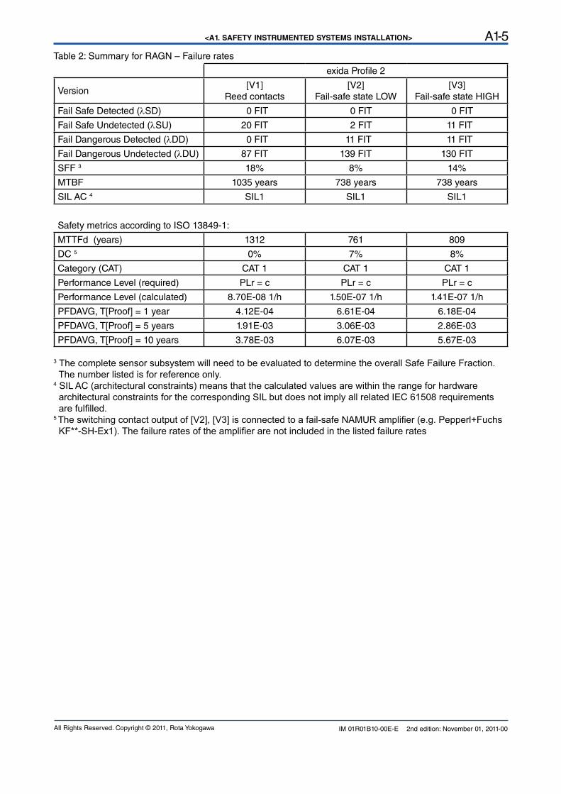
A1.4 Assessment results
A1.4.1 Safety related parameters
The following results have been obtained from the assessment report Report No.: ROTA YOKOGAWA 11/04-36 R004 Version V1, Revision R1; November 2011 issued by exida.
Average PFD values have been calculated assuming a Diagnostic Coverage (DC) of 99%, a mission time of 10 years and a Mean Time to Restoration of 24 hours.
<A1. SAFETY INSTRUMENTED SYSTEMS INSTALLATION> A1-5
IM 01R01B10-00E-E 2nd edition: November 01, 2011-00All Rights Reserved. Copyright © 2011, Rota Yokogawa
Table 2: Summary for RAGN – Failure rates
exida Profile 2
Version[V1]
Reed contacts[V2]
Fail-safe state LOW[V3]
Fail-safe state HIGH
Fail Safe Detected (lSD) 0 FIT 0 FIT 0 FIT
Fail Safe Undetected (lSU) 20 FIT 2 FIT 11 FIT
Fail Dangerous Detected (lDD) 0 FIT 11 FIT 11 FIT
Fail Dangerous Undetected (lDU) 87 FIT 139 FIT 130 FIT
SFF 3 18% 8% 14%
MTBF 1035 years 738 years 738 years
SIL AC 4 SIL1 SIL1 SIL1
Safety metrics according to ISO 13849-1:
MTTFd (years) 1312 761 809
DC 5 0% 7% 8%
Category (CAT) CAT 1 CAT 1 CAT 1
Performance Level (required) PLr = c PLr = c PLr = c
Performance Level (calculated) 8.70E-08 1/h 1.50E-07 1/h 1.41E-07 1/h
PFDAVG, T[Proof] = 1 year 4.12E-04 6.61E-04 6.18E-04
PFDAVG, T[Proof] = 5 years 1.91E-03 3.06E-03 2.86E-03
PFDAVG, T[Proof] = 10 years 3.78E-03 6.07E-03 5.67E-03
3 The complete sensor subsystem will need to be evaluated to determine the overall Safe Failure Fraction. The number listed is for reference only.4 SIL AC (architectural constraints) means that the calculated values are within the range for hardware architectural constraints for the corresponding SIL but does not imply all related IEC 61508 requirements are fulfilled.5 The switching contact output of [V2], [V3] is connected to a fail-safe NAMUR amplifier (e.g. Pepperl+Fuchs KF**-SH-Ex1). The failure rates of the amplifier are not included in the listed failure rates

IM 01R01B10-00E-E 2nd edition: November 01, 2011-00All Rights Reserved. Copyright © 2011, Rota Yokogawa
Yokogawa has an extensive sales and distribution network. Please refer to the European website (www.yokogawa.com/eu) to contact your nearest representative.
Euroweg 23825 HD AMERSFOORTThe Netherlandswww.yokogawa.com/eu
YOKOGAWA ELECTRIC CORPORATIONWorld Headquarters9-32, Nakacho 2-chome, Musashino-shiTokyo 180-8750Japanwww.yokogawa.com
YOKOGAWA CORPORATION OF AMERICA2 Dart RoadNewnan GA 30265USAwww.yokogawa.com/us
YOKOGAWA ELECTRIC ASIA Pte. LTD.5 Bedok South RoadSingapore 469270Singaporewww.yokogawa.com/sg
YOKOGAWA CHINA CO. LTD.3F Tower D Cartelo Crocodile BuildingNo.568 West Tianshan Road Changing DistrictShanghai, Chinawww.yokogawa.com/cn
YOKOGAWA MIDDLE EAST B.S.C.(c)P.O. Box 10070, ManamaBuilding 577, Road 2516, Busaiteen 225Muharraq, Bahrainwww.yokogawa.com/bh
RotameterTM is a trademark of Rota Yokogawa GmbH & Co. KG, a subsidiary of Yokogawa Electric Corporation, Japan. In the United Kingdom RotameterTM is a trademark of
Emerson Electric Co.
Subject to change without notice


![Section 4€¦ · Type 807 Rotameter - Polyamide Complete Assembly PVC Socket Ends, FPM Seals, Standard Tube C Size [inch] Standard Float Part No. USD Magnetic Float Part No. USD](https://static.fdocuments.net/doc/165x107/602ccc08e416c1071f49a196/section-4-type-807-rotameter-polyamide-complete-assembly-pvc-socket-ends-fpm.jpg)


![Rotameters · Type 807 Rotameter - Polysulphone Complete Assembly PVC Socket Ends, EPDM Seals, Short Tube C Size [inch] Standard Float Part No. Magnetic Float Part No. Flow Range](https://static.fdocuments.net/doc/165x107/5f91f8914732fd75b358e481/rotameters-type-807-rotameter-polysulphone-complete-assembly-pvc-socket-ends.jpg)