SERVOMOTORI BRUSHLESS BRUSHLESS SERVOMOTORS - … · • Elevato rendimento dinamico • Ottime...
56
1 SERVOMOTORI BRUSHLESS BRUSHLESS SERVOMOTORS
Transcript of SERVOMOTORI BRUSHLESS BRUSHLESS SERVOMOTORS - … · • Elevato rendimento dinamico • Ottime...

1
SERVOMOTORI BRUSHLESSBRUSHLESS SERVOMOTORS

INDICE
INDEX
Informazioni Generali 3 General Information
Trasduttori e Connessioni 4 Transducers and Connections
PRO LINE ONE - Caratteristiche tecniche 8 PRO LINE ONE - Technical features
PRO LINE ONE - Designazione del servomotore 9 PRO LINE ONE - Ordering code
PRO LINE ONE S040 - Dimensioni e tolleranze 10 PRO LINE ONE S040 - Dimensions and tolerances
PRO LINE ONE S060 - Dimensioni e tolleranze 13 PRO LINE ONE S060 - Dimensions and tolerances
PRO LINE ONE S080 - Dimensioni e tolleranze 16 PRO LINE ONE S080 - Dimensions and tolerances
PRO LINE TWO - Caratteristiche tecniche 22 PRO LINE TWO - Technical features
PRO LINE TWO - Designazione del servomotore 23 PRO LINE TWO - Ordering code
PRO LINE TWO S100 - Dimensioni e tolleranze 24 PRO LINE TWO S100 - Dimensions and tolerances
PRO LINE TWO S120 - Dimensioni e tolleranze 27 PRO LINE TWO S120 - Dimensions and tolerances
PRO LINE TWO S140 - Dimensioni e tolleranze 30 PRO LINE TWO S140 - Dimensions and tolerances
Direttive Europee e Standards - PRO LINE 34 European Directives and Standards - PRO LINE
PRO LAB ONE - Informazioni Generali 38 PRO LAB ONE - General Information
PRO LAB FOUR - Informazioni Generali 46 PRO LAB FOUR - General Information
Direttive Europee e Standards - PRO LAB 52 European Directives and Standards - PRO LAB

3
INFORMAZIONI GENERALI
GENERAL INFORMATION
La serie Pro Line identifica motori sincroni a magneti permanenti, altrimenti detti A.C. brushless. Comprende 6 taglie con differenti configurazioni e potenze, nate per coprire tutte le esigenze dell’automazione industriale di alta gamma:
• Compattezza• Elevata densità di potenza• Elevato rendimento dinamico• Ottime prestazioni dinamiche• Elevata regolarità di rotazione
Queste peculiarità sono frutto di un’attenta e mirata progettazione, per mezzo di strumenti di ultima generazione, come simulazioni fem in 3D.Altresì l’utilizzo di materiali nobili e tecnologicamente avanzati, la scelta ponderata delle tolleranze di accoppiamento e la cura negli assemblaggi, fanno di questi servomotori delle macchine affidabili e con caratteristiche ripetibili dal primo all’ultimo.
Il lamierino magnetico è realizzato su nostro progetto e ottimizzato per il magnete radiale che, utilizzando un avvolgimento detto “concentrato”, permette di ottenere motori massimizzati sotto il profilo delle prestazioni, salvando spazio inutile.
The PRO LINE motor series is a range of permanent magnet synchronous motors, otherwise known as A.C. brushless. There are 6 frame sizes offering different performances and powers which were developed specifically to meet the needs of the industrial automation sector. The main features are:
• Compactness• High power density• High efficiency• High dynamic response• Smooth rotation
These features are a result of great attention to detail in the research and planning stages and the use of ultimate generation software and instrumentation in the design and development process, for example 3D fem simulations. The thought given to minimising the coupling tolerances and the assembly processes, combined with using best quality materials results in a series which has such a high attention to detail it is rendered an artisan-like product yet the production process has been studied to ensure this quality is maintained in large batch production. The design of the stator pack is optimized for radial magnets and a “compressed winding” is used to produce high power motors in the smallest dimensions possible.

TRASDUTTORI E CONNESSIONI
TRANSDUCERS AND CONNECTIONS
4
CABLAGGIO CAVO - CABLE WIRING
ENCODER
Potenza - Power terminal
PIN Segnale - Signal
1 U
2 V
3 W
4 GND
5 BRK - (2)
6 BRK + (2)
7 KTY - (1)
8 KTY + (1)
9 n.c.
Segnale - Signal
PIN Resolver RE2P Encoder incrementale Incremental encoder
1 GND / 0V +5 Vdc
2 COS + A -
3 + Vms GND / 0V
4 COS - HALL V
5 SEN + HALL W
6 SEN - HALL U
7 KTY - (*) Z -
8 KTY + (*) B
9 n.c. B -
10 n.c. A11 n.c. Z
12 Shield Shield
Sigla - Type Descrizione -Description S040 S060 S080 S100 S120 S140
RES Resolver 2 poliResolver 2 poles • • • • • •
F 2048 Encoder Incrementale 2048 PPRIncremental encoder 2048 PPR • • • • • •
AD36 Encoder assoluto BISS multigiroAbsolute encoder BISS multiturn - • • • • •
SEK Encoder assoluto SIN/COS monogiro HiperfaceAbsolute encoder SIN/COS singleturn Hiperface • • • • • •
SEL Encoder assoluto SIN/COS multigiro HiperfaceAbsolute encoder SIN/COS multiturn Hiperface • • • • • •
DSL Encoder assoluto multigiro Hiperface DSLAbsolute encoder multiturn Hiperface DSL - • • • • •
(*) Sonda termica KTY84-130 su richiesta - KTY84-130 temperature sensor on request
(1) Su richiesta - On request (2) Se presente - If present

CABLAGGIO CONNETTORE - CONNECTOR WIRING
5
M17 Power connector(40, 60, 80 series) C11
M23 Power connector(100, 120, 140 series) C12
Potenza - Power terminalM17 M23
PIN Segnale - Signal PIN Segnale - Signal1 U A U2 V B V3 W C W
GND GNDA BRK+ (2) E KTY+ (1)
B BRK- (2) F BRK- (2)
C KTY- (1) G BRK+ (2)
D - H -E KTY+ (1) L KTY- (1)
(1) Su richiesta - On request (2) Se presente - If present
M17 Signal connector(40, 60, 80 series) C2
M23 Signal connector(100, 120, 140 series) C6
2
3
1
4
5
67
8
910
11
1213
1415
16
17
Segnale - Signal
PIN Resolver RE2p Encoder incrementaleIncremental encoder
Encoder assoluto - Absolute encoder
BISS SIN/COS
1 COS - B B n.c.
2 COS + B - B - n.c.
3 SEN - Z CLOCK SIN +
4 SEN + HALL U 5V sensor Ref SIN
5 n.c. HALL W 0V sensor Ref COS
6 n.c. n.c. n.c. n.c.
7 Shield GND / 0V GND / 0V GND / 0V
8 KTY+ (*) KTY+ (*) KTY+ (*) KTY+ (*)
9 KTY- (*) KTY- (*) KTY- (*) KTY- (*)
10 n.c. +5 Vdc +5 Vdc +V dc
11 n.c. A A n.c.
12 n.c. A - A - n.c.
13 n.c. Z - CLOCK - COS +
14 +V dc HALL U - DATA - DATA -
15 GND / 0V HALL V - n.c. n.c.
16 n.c. HALL V DATA DATA +
17 n.c. HALL W - n.c. n.c.
(*) Su richiesta - On request


50 - 750 Watt
SERVOMOTORI BRUSHLESSBRUSHLESS SERVOMOTORS

88
CARATTERISTICHE TECNICHE
TECHNICAL FEATURES
Servomotori Pro Line - Pro Line servomotorsTipo di macchina Type of machine
Servomotore sincrono a magneti permanentiA.C. permanent magnet synchronous servomotor
Tipo di avvolgimento Winding type
Avvolgimento concentratoCompressed winding
MagnetiMagnets
Nd-Fe-B anisotropi a orientamento radialeRadially oriented, anisotropic Nd-Fe-B ring magnets
Coppie polari Pole pairs 3 / 4
Coppia di stallo Stall torque
Da 0,16 a 2,5NmFrom 0,16 to 2,5Nm
Forma costruttiva Design B5, V1, V3 (EN 60034 - 5)
Grado di protezione Degree of protection IP65 standard (EN 60034 - 5)
Classe di isolamento Insulation class
Isolamento classe FF class insulation
Finitura esternaExternal finish
Carcassa pallinata e anodizzata bianca antigraffio Antiscratch sanded white anodized body
Albero di trazione Shaft
Albero con sede linguetta UNI6604 e foro in testaShaft with UNI6604 keyway and threaded hole
CuscinettiBearings
Cuscinetti a sfere di alta qualità con tenute striscianti lubrificati a vitaHigh quality sealed life lubricated bearings
RaffreddamentoCooling
Vedi note fondo paginaSee notes below
TrasduttoreTransducer
Encoder incrementale 2048 PPR / Encoder assoluto 12-18 bits / Resolver 2 poliIncremental encoders 2048 PPR / Absolute encoders 12-18 bits / 2 poles Resolver
AlimentazionePower supply
Cavo con connettore Molex minifit jr o connettore circolare orientabile a 90°Cable with Molex Minifit jr connector or Rotatable angled circular connectors
Sensore termicoThermal sensor KTY84-130
RaffredamentoTutti i dati dei servomotori della serie Pro Line, sono riferiti ad una temperatura ambiente di max. 40°C, altitudine max. 1000m s.l.m. e montati su flangia di alluminio di 250x250x6mm.Se il motore è montato in aria (isolato) i dati nominali devono essere ridotti.Per installazioni in ambienti con temperatura superiore ai 40°C, i dati di targa devono essere ridotti di circa 1% per 1°C.Per installazioni al di sopra dei 100m s.l.m. va tenuto conto di una riduzione di potenza di circa 1% per ogni 100m di altitudine. La quota massima permessa e 4000m s.l.m.
CoolingAll specified ratings of Pro Line servomotors refer to a max ambient temperature of 40°C and an installation altitude of max 1000m a.s.l., mounted an aluminium plate of 250x250x6mm.If the motor is to be mounted in free still air (no heat discharge), the absolute ratings need to be reduced.With ambient temperature>40°C a power reduction of 1% per 1°C is required.For installation altitude>1000m a.s.l. a power reduction of 1% per 100m is required. The max.installation altitude is 4000m.

99
DESIGNAZIONE DEL SERVOMOTORE
ORDERING CODE
Esempio ordinativo
S0802B375 F2048 FE 19x40 70-90 C11C2 KTY84
Si definisce un servomotore Pro Line con leseguenti caratteristiche:
• Taglia 080• Lunghezza 2• Codice Avvolgimento 375• Encoder incrementale+hall a 2048 impulsi per giro• Opzione freno• Albero Ø19x40• Flangia 70-90• Alimentazione a connettori M17 orientabili a 90°• Sensore termico KTY84-130
Diametro e lunghezza alberoShaft diameter and lenght
Centraggio e interasse fori flangia Flange coupling and pitch circle diameter
Connessioni P13P13 – C11C2 (*) Connections P13P13 - C11C2 (*)
Sensore Termico Thermal sensor
Opzione frenoBrake Option
Tipo di trasduttore (vedi tabella pag.4)Transducer type (see table pag.4)
Codice Avvolgimento (vedi datasheets)Winding code (see datasheets)
Lunghezza 1 - 2Overall Length 1 - 2
Taglia 040 - 060 - 080 Size 040 - 060 - 080
S B
Order example
S0802B375 F2048 FE 19x40 70-90 C11C2 KTY84
This code identifies the following servomotor:
• Size 080• Overall length 2• Winding code 375• Incremental encoder+hall 2048ppr• Brake option• Shaft Ø19x40• Flange 70-90• Power supply by rotatable angled 90° M17 connectors• Thermal sensor KTY84-130
080 375 F20481 FE DA19X40 70-90 C11C2 KTY84
(*) Alimentazione con cavo terminato dalla parte utente con connettore molex tipo minifit jr a 6 poli per la potenza e 12 poli per il segnale.Alimentazione tramite connettori circolari multipolari orientabili a 90° M17.
(*) Cable wiring with molex minfit jr connectors: 6 poles for power, 12 poles for signal.Circular rotatable 90° connectors M17.

1010
Fra parentesi dimensioni relative a motore con freno di stazionamento con Cn ≥ Mn motore elettrico - The dimensions in brackets are for a motor with brake with Cn ≥ Mn motor.
Servosistemi Pro-Line - Pro-Line A.C. servosystems
Type S040 L LL LR LG LC ØLA ØLZ ØS h6 ØLB QK QD U W T
S0401B 102 (142) 127.5 (167.5) 25.5 9 40 46 4.5 8 30 15 2 9.2 3 3
S0402B 117 (159) 142 (184.5) 25.5 9 40 46 4.5 8 30 15 2 9.2 3 3
PROLINE S040 - DIMENSIONI E TOLLERANZE
PROLINE S040 - DIMENSIONS AND TOLERANCES
57
67
90
90

11
PROLINE S040 - PRESTAZIONI E SPECIFICHE
PROLINE S040 - PERFORMANCE AND SPECIFICATIONS
11
Tipo - Type S040 Prestazioni e Specifiche - Performance and Specifications
Tensione Alimentazione - Applied Voltage 17 VAC 32 VAC 17 VAC 32 VAC 230 VAC
Modello Servomotore - Servomotor Model 1B 348 1B 349 2B 350 2B 354 2B 351
∆T MAX Avvolgimenti ∆T MAX Winding °C 65 105 65 105 65 105 65 105 65 105
Potenza Nominale Rated Power W 37 50 37 50 75 100 75 100 75 100
Coppia di Stallo Stall Torque Nm 0.13 0.18 0.13 0.18 0.29 0.34 0.29 0.34 0.29 0.34
Corrente di Stallo Stall Current Arms 2.66 3.55 1.27 1.70 5.70 6.70 2.78 3.27 0.44 0.51
Coppia Nominale Rated Torque Nm 0.12 0.16 0.12 0.16 0.27 0.32 0.27 0.32 0.27 0.32
Corrente Nominale Rated Current Arms 2.47 3.20 1.15 1.55 5.50 6.58 2.70 3.23 0.43 0.50
Coppia di Picco Istantanea Instantaneous Peak Torque Nm 0.54 0.96
Corrente di Picco Istantanea Instantaneous Peak Current Arms 10.65 5.10 17.10 9.80 1.53
Velocità Nominale Rated Speed rpm 3000
Massima Velocità Max Speed rpm 5000 4000 5000 4000 5000
Costante di Coppia ± 5% (1) Torque Constant ± 5% (1) Nm/Arms 0.051 0.104 0.051 0.104 0.660
Costante di Tensione ± 5% Voltage Constant ± 5% Vrms /krpm 3.1 6.3 3.1 6.3 40.0
Resistenza di Avvolgimento ± 5% (1) Winding Resistance ± 5% Ω 1.22 4.38 0.49 1.76 68.80
Induttanza di Avvolgimento Winding Inductance mH 0.90 3.73 0.53 2.20 88.00
Momento di Inerzia Rotorico Rotor Moment of Inertia kg·m2x10-4 0.032 0.06
Massa Mass kg 0.4 0.65
Massimo Carico Radiale Maximum Radial Load N 120
Massimo Carico Assiale Maximum Axial Load N 80
Freno (Opzionale) - Brake (option)
Tensione nominale ±10% Rated voltage ±10% Vdc 24
Corrente nominale a 20°CRated current at 20°C A 0.33
Massima velocitàMax speed Rpm 10000
Momento di inerziaMoment of inertia kg·m2x10-4 0,013
PesoMass kg 0,08
Coppia frenanteBreaking torque Nm 0.4
(*) Flangia in Alluminio 250x250x6 mm - Aluminium Flange 250x250x6 mm ( 1 ) @ 25°C
Servizio - Time RatingClasse di Isolamento - Insulation Class
Temp. Ambiente - Ambient Temp.Grado di Protezione - Level of Protection
Chiusura - Enclosure Montaggio - Mounting
Continuo - ContinuousClasse F - F Class0 to +40° CIP65 Totalmente Chiuso, ventilato per convezione naturale - Totally enclosed, self cooled Accoppiato a Flangia - Flange Mounted (*)Ca
ratte
ristic
he
Char
acte
ristic
s

12
PROLINE S040 - PRESTAZIONI E SPECIFICHE
PROLINE S040 - PERFORMANCE AND SPECIFICATIONS
12
Caratteristiche Coppia/Velocità - Torque/Speed Characteristics
351
0
1000
2000
3000
4000
5000
0 0,25 0,5 0,75 1
Coppia - Torque [Nm]
Vel
ocit
à - S
peed
[Rpm
]
354
0
1000
2000
3000
4000
0 0,25 0,5 0,75 1
Coppia - Torque [Nm]
Vel
ocit
à - S
peed
[Rpm
]
353
0
1000
2000
3000
4000
5000
0 0,25 0,5 0,75 1
Coppia - Torque [Nm]
Vel
ocit
à - S
peed
[Rpm
]
∆T = 65° C; ∆T = 105° C; Peak Torque

13
Servosistemi Pro-Line - Pro-Line A.C. servosystems
13
PROLINE S060 - DIMENSIONI E TOLLERANZE
PROLINE S060 - DIMENSIONS AND TOLERANCES
9090
67
77
Fra parentesi dimensioni relative a motore con freno di stazionamento con Cn ≥ Mn motore elettrico - The dimensions in brackets are for a motor with brake with Cn ≥ Mn motor.
Type S060 L LL LR LG LC ØLA ØLZ ØS h6 ØLB h7 QK QD U W T
S0601B 128.5 (173) 158.5 (203)30 10 60 70 5.5 14 50 20 3 16 5 5
S0602B 163.5 (208) 193.5 (238)

14
PROLINE S060 - PRESTAZIONI E SPECIFICHE
PROLINE S060 - PERFORMANCE AND SPECIFICATIONS
14
Tipo - Type S060 Prestazioni e Specifiche - Performance and Specifications
Tensione Alimentazione - Applied Voltage 32 VAC 230 VAC 32 VAC 230 VAC
Modello Servomotore - Servomotor Model 1B 303 1B 302 2B 305 2B 301
∆T MAX Avvolgimenti ∆T MAX Winding °C 65 105 65 105 65 105 65 105
Potenza Nominale Rated Power W 220 250 220 250 314 400 314 400
Coppia di Stallo Stall Torque Nm 0.75 0.87 0.75 0.85 1.15 1.37 1.15 1.37
Corrente di Stallo Stall Current Arms 4.71 5.47 1.25 1.42 7.90 9.40 1.56 1.86
Coppia Nominale Rated Torque Nm 0.70 0.80 0.70 1.50 1.00 1.27 1.00 1.27
Corrente Nominale Rated Current Arms 4,60 5.30 1.22 1.40 7.20 9.15 1.42 1.80
Coppia di Picco Istantanea Instantaneous Peak Torque Nm 2.61 4.11
Corrente di Picco Istantanea Instantaneous Peak Current Arms 16.40 4.26 28.20 5.58
Velocità Nominale Rated Speed rpm 3000
Massima Velocità Max Speed rpm 4000
Costante di Coppia ± 5% (1) Torque Constant ± 5% (1) Nm/Arms 0.159 0.600 0.146 0.736
Costante di Tensione ± 5% Voltage Constant ± 5% Vrms /krpm 9.63 32.00 8.85 44.60
Resistenza di Avvolgimento ± 5% (1) Winding Resistance ± 5% Ω 0.85 12.41 0.37 8.47
Induttanza di Avvolgimento Winding Inductance mH 2.63 38.14 1.21 30.00
Momento di Inerzia Rotorico Rotor Moment of Inertia kg·m2x10-4 0.19 0.30
Massa Mass kg 1.2 2.0
Massimo Carico Radiale Maximum Radial Load N 250
Massimo Carico Assiale Maximum Axial Load N 80
Servizio - Time RatingClasse di Isolamento - Insulation Class
Temp. Ambiente - Ambient Temp.Grado di Protezione - Level of Protection
Chiusura - Enclosure Montaggio - Mounting
Continuo - ContinuousClasse F - F Class0 to +40° CIP65 Totalmente Chiuso, ventilato per convezione naturale - Totally enclosed, self cooled Accoppiato a Flangia - Flange Mounted (*)Ca
ratte
ristic
he
Char
acte
ristic
s
Freno (Opzionale) - Brake (option)
Tensione nominale ±10% Rated voltage ±10% Vdc 24
Corrente nominale a 20°CRated current at 20°C A 0.46
Massima velocitàMax speed Rpm 10000
Momento di inerziaMoment of inertia kg·m2x10-4 0,068
PesoMass kg 0.15
Coppia frenanteBreaking torque Nm 2
(*) Flangia in Alluminio 250x250x6 mm - Aluminium Flange 250x250x6 mm ( 1 ) @ 25°C

15
PROLINE S060 - PRESTAZIONI E SPECIFICHE
PROLINE S060 - PERFORMANCE AND SPECIFICATIONS
15
Caratteristiche Coppia/Velocità - Torque/Speed Characteristics
301
0
1000
2000
3000
4000
0 1 2 3 4 5
Coppia - Torque [Nm]
Vel
ocit
à - S
peed
[Rpm
]
∆T = 65° C; ∆T = 105° C; Peak Torque
305
0
1000
2000
3000
4000
0 1 2 3 4 5
Coppia - Torque [Nm
Vel
ocit
à - S
peed
[Rpm
]
302
0
1000
2000
3000
4000
0 0,5 1 1,5 2 2,5 3
Coppia - Torque [Nm]
Vel
ocit
à - S
peed
[Rpm
]
303
Coppia - Torque [Nm]
0
1000
2000
3000
4000
0 0,5 1 1,5 2 2,5 3
Vel
ocit
à - S
peed
[Rpm
]

1616
PROLINE S080 - DIMENSIONI E TOLLERANZE
PROLINE S080 - DIMENSIONS AND TOLERANCES
Fra parentesi dimensioni relative a motore con freno di stazionamento con Cn ≥ Mn motore elettrico - The dimensions in brackets are for a motor with brake with Cn ≥ Mn motor.
Type S080 L LL LR LG LC ØLA ØLZ ØS h6 ØLB h7 QK QD U W T
S0801B 130 (179) 170 (219)40 13 80 90 7 16
19 70 30 3 1821.5
56
56S0802B 160 (209) 200 (249)
Servosistemi Pro-Line - Pro-Line A.C. servosystems
6MA x 12mm
4 x øLZon øLA pcd
9090
77
87

17
PROLINE S080 - PRESTAZIONI E SPECIFICHE
PROLINE S080 - PERFORMANCE AND SPECIFICATIONS
17
Tipo - Type S080 Prestazioni e Specifiche - Performance and Specifications
Tensione Alimentazione - Applied Voltage 230 VAC 230 VAC 400 VAC
Modello Servomotore - Servomotor Model 1B 373 2B 375 2B 377
∆T MAX Avvolgimenti ∆T MAX Winding °C 65 105 65 105 65 105
Potenza Nominale Rated Power W 315 400 567 750 567 750
Coppia di Stallo Stall Torque Nm 1.15 1.4 2.1 2.5 2.1 2.5
Corrente di Stallo Stall Current Arms 1.42 1.73 2.40 2.90 1.40 1.66
Coppia Nominale Rated Torque Nm 1.00 1.27 1.80 2.39 1.80 2.39
Corrente Nominale Rated Current Arms 1.30 1.65 2.20 2.75 1.26 1.30
Coppia di Picco Istantanea Instantaneous Peak Torque Nm 4.2 7.5
Corrente di Picco Istantanea Instantaneous Peak Current Arms 5.20 8.70 5.00
Velocità Nominale Rated Speed rpm 3000
Massima Velocità Max Speed rpm 4000
Costante di Coppia ± 5% (1) Torque Constant ± 5% (1) Nm/Arms 0.74 0.85 1.500
Costante di Tensione ± 5% Voltage Constant ± 5% Vrms /krpm 47.10 51.40 91.20
Resistenza di Avvolgimento ± 5% (1) Winding Resistance ± 5% Ω 8.70 3.95 12.20
Induttanza di Avvolgimento Winding Inductance mH 47.00 29.50 89.00
Momento di Inerzia Rotorico Rotor Moment of Inertia kg·m2x10-4 0.366 0.614
Massa Mass kg 2.1 3.1
Massimo Carico Radiale Maximum Radial Load N 420
Massimo Carico Assiale Maximum Axial Load N 150
Freno (Opzionale) - Brake (option)
Tensione nominale ±10% Rated voltage ±10% Vdc 24
Corrente nominale a 20°CRated current at 20°C A 0.5
Massima velocitàMax speed Rpm 10000
Momento di inerziaMoment of inertia kg·m2x10-4 0.18
PesoMass kg 0.3
Coppia frenanteBreaking torque Nm 4.5
(*) Flangia in Alluminio 250x250x6 mm - Aluminium Flange 250x250x6 mm ( 1 ) @ 25°C
Servizio - Time RatingClasse di Isolamento - Insulation Class
Temp. Ambiente - Ambient Temp.Grado di Protezione - Level of Protection
Chiusura - Enclosure Montaggio - Mounting
Continuo - ContinuousClasse F - F Class0 to +40° CIP65 Totalmente Chiuso, ventilato per convezione naturale - Totally enclosed, self cooled Accoppiato a Flangia - Flange Mounted (*)Ca
ratte
ristic
he
Char
acte
ristic
s

18
PROLINE S080 - PRESTAZIONI E SPECIFICHE
PROLINE S080 - PERFORMANCE AND SPECIFICATIONS
18
Caratteristiche Coppia/Velocità - Torque/Speed Characteristics
375
0
1000
2000
3000
4000
0 2 4 6 8
Coppia - Torque [Nm]
Vel
ocit
à - S
peed
[Rpm
]
377
0
1000
2000
3000
4000
0 2 4 6 8
Coppia - Torque [Nm]
Vel
ocit
à - S
peed
[R
pm]
∆T = 65° C; ∆T = 105° C; Peak Torque
373
0
1000
2000
3000
4000
0 1 2 3 4 5
Coppia-Torque [Nm ]
Vel
ocit
à - S
peed
[ rp
m ]

19
Caratteristiche Coppia/Velocità - Torque/Speed Characteristics
375
0
1000
2000
3000
4000
0 2 4 6 8
Coppia - Torque [Nm]
Vel
ocit
à - S
peed
[Rpm
]
377
0
1000
2000
3000
4000
0 2 4 6 8
Coppia - Torque [Nm]
Vel
ocit
à - S
peed
[R
pm]
∆T = 65° C; ∆T = 105° C; Peak Torque
373
0
1000
2000
3000
4000
0 1 2 3 4 5
Coppia-Torque [Nm ]
Vel
ocit
à - S
peed
[ rp
m ]
NOTE
NOTES


1050 - 3500 Watt
SERVOMOTORI BRUSHLESSBRUSHLESS SERVOMOTORS

22
CARATTERISTICHE TECNICHE
TECHNICAL FEATURES
Servomotori Pro Line - Pro Line servomotorsTipo di macchina Type of machine
Servomotore sincrono a magneti permanentiA.C. permanent magnet synchronous servomotor
Tipo di avvolgimento Winding type
Avvolgimento concentratoCompressed winding
MagnetiMagnets
Magneti permanenti NdFeb sinterizzati, incollati e protettiSynterered NdFeb magnets fastened
Coppie polari Pole pairs 5
Coppia di stallo Stall torque
Da 4 a 19NmFrom 4 to 19Nm
Forma costruttiva Design B5, V1, V3 (EN 60034 - 5)
Grado di protezione Degree of protection IP65 standard (EN 60034 - 5)
Classe di isolamento Insulation class
Isolamento classe FF class insulation
Finitura esternaExternal finish
Carcassa pallinata e anodizzata bianca antigraffio Antiscratch sanded white anodized body
Albero di trazione Shaft
Albero con sede linguetta UNI6604 e foro in testaShaft with UNI6604 keyway and threaded hole
CuscinettiBearings
Cuscinetti a sfere di alta qualità con tenute striscianti lubrificati a vitaHigh quality sealed life lubricated bearings
RaffreddamentoCooling
Vedi note fondo paginaSee notes below
TrasduttoreTransducer
Encoder incrementale 2048 PPR / Encoder assoluto 12-18 bits / Resolver 2 poliIncremental encoders 2048 PPR / Absolute encoders 12 -18 bits / 2 poles Resolver
AlimentazionePower supply
Connettore circolare orientabile a 90°Rotatable angled circular connectors
Sensore termicoThermal sensor KTY84-130
RaffredamentoTutti i dati dei servomotori della serie Pro Line, sono riferiti ad una temperatura ambiente di max. 40°C, altitudine max. 1000m s.l.m. e montati su flangia di alluminio di 350x350x20mm.Se il motore è montato in aria (isolato) i dati nominali devono essere ridotti.Per installazioni in ambienti con temperatura superiore ai 40°C, i dati di targa devono essere ridotti di circa 1% per 1°C.Per installazioni al di sopra dei 100m s.l.m. va tenuto conto di una riduzione di potenza di circa 1% per ogni 100m di altitudine. La quota massima permessa e 4000m s.l.m.
CoolingAll specified ratings of Pro Line servomotors refer to a max ambient temperature of 40°C and an installation altitude of max 1000m a.s.l., mounted an aluminium plate of 350x350x20mm.If the motor is to be mounted in free still air (no heat discharge), the absolute ratings need to be reduced.With ambient temperature>40°C a power reduction of 1% per 1°C is required.For installation altitude>1000m a.s.l. a power reduction of 1% per 100m is required. The max.installation altitude is 4000m.

23
DESIGNAZIONE DEL SERVOMOTORE
ORDERING CODE
Esempio ordinativo
S1001B324 SEL FE 19x40 95-115 C12C6 KTY84
Si definisce un servomotore Pro Line con leseguenti caratteristiche:
• Taglia 100• Lunghezza 1• Codice Avvolgimento 324• Encoder assoluto 12 bit sin/cos multigiro• Opzione freno• Albero Ø19x40• Flangia 95-115• Alimentazione a connettori M23 orientabili a 90°• Sensore termico KTY84-130
Diametro e lunghezza alberoShaft diameter and lenght
Centraggio e interasse fori flangia Flange coupling and pitch circle diameter
Alimentazione C12C6(*) Power supply C12C6(*)
Opzione frenoBrake Option
Tipo di trasduttore (vedi tabella pag.4)Transducer type (see table pag.4)
Codice Avvolgimento (vedi datasheets)Winding code (see datasheets)
Lunghezza 0 - 1 - 2Overall Length 0 - 1 - 2
Taglia 100-120-140 Size 100-120-140
S B
Order example
S1001B324 SEL FE 19x40 95-115 C12C6 KTY84
This code identifies the following servomotor:
• Size 100• Overall length 1• Winding code 324• Absolute encoder 12 bit sin/cos multiturn• Brake option• Shaft Ø19x40• Flange 95-115• Power supply by rotatable angled 90° M23 connectors• Thermal sensor KTY84-130
100 324 SEL1 FE DA19X40 95-115 C12C6
(*) Alimentazione tramite connettori circolari multipolari orientabili a 90° M23.
(*) Circular rotatable 90° connectors M23.
Sensore Termico Thermal sensor
KTY84

24
Servosistemi Pro-Line - Pro-Line A.C. servosystems
PROLINE S100 - DIMENSIONI E TOLLERANZE
PROLINE S100 - DIMENSIONS AND TOLERANCES
Fra parentesi dimensioni relative a motore con freno di stazionamento con Cn ≥ Mn motore elettrico - The dimensions in brackets are for a motor with brake with Cn ≥ Mn motor.
Type S100 L LL LR LG LC ØLA ØLZ ØS h6 ØLB h7 QK QD U W T
S1001B 175 (225) 215 (265)40 14 98 115 9 19 95 30 3 21.5 6 6
S1002B 230 (280) 270 (320)
3

25
PROLINE S100 - PRESTAZIONI E SPECIFICHE
PROLINE S100 - PERFORMANCE AND SPECIFICATIONS
Servizio - Time RatingClasse di Isolamento - Insulation Class
Temp. Ambiente - Ambient Temp.Grado di Protezione - Level of Protection
Chiusura - Enclosure Montaggio - Mounting
Continuo - ContinuousClasse F - F Class0 to +40° CIP65 Totalmente Chiuso, ventilato per convezione naturale - Totally enclosed, self cooled Accoppiato a Flangia - Flange Mounted (*)Ca
ratte
ristic
he
Char
acte
ristic
s
Freno (Opzionale) - Brake (option)
Tensione nominale ±10% Rated voltage ±10% Vdc 24
Corrente nominale a 20°CRated current at 20°C A 0.75
Massima velocitàMax speed Rpm 10000
Momento di inerziaMoment of inertia kg·m2x10-4 0,54
PesoMass kg 0.46
Coppia frenanteBreaking torque Nm 9
(*) Flangia in Alluminio 250x250x6 mm - Aluminium Flange 250x250x6 mm ( 1 ) @ 25°C
Tipo - Type S100 Prestazioni e Specifiche - Performance and Specifications
Tensione Alimentazione - Applied Voltage 230 VAC 400 VAC 400 VAC
Modello Servomotore - Servomotor Model 1B 324 1B 325 2B 329
∆T MAX Avvolgimenti ∆T MAX Winding °C 105 322
Potenza Nominale Rated Power W 1050 1050 1700
Coppia di Stallo Stall Torque Nm 4 4.7 7.5
Corrente di Stallo Stall Current Arms 5.10 3.60 5.40
Coppia Nominale Rated Torque Nm 3.50 3.50 5.40
Corrente Nominale Rated Current Arms 4.50 2.20 4.00
Coppia di Picco Istantanea Instantaneous Peak Torque Nm 12 22.5
Corrente di Picco Istantanea Instantaneous Peak Current Arms 19.90 12.00 16.20
Velocità Nominale Rated Speed rpm 3000
Massima Velocità Max Speed rpm 4000
Costante di Coppia ± 5% (1) Torque Constant ± 5% (1) Nm/Arms 0.820 1.340 1.35
Costante di Tensione ± 5% Voltage Constant ± 5% Vrms /krpm 50.00 85.30 85.30
Resistenza di Avvolgimento ± 5% (1) Winding Resistance ± 5% Ω 1.40 3.50 1.30
Induttanza di Avvolgimento Winding Inductance mH 13.50 36.00 15.00
Momento di Inerzia Rotorico Rotor Moment of Inertia kg·m2x10-4 2.7 5.5
Massa Mass kg 5.0 9.0
Massimo Carico Radiale Maximum Radial Load N 600
Massimo Carico Assiale Maximum Axial Load N 150

PROLINE S100 - PRESTAZIONI E SPECIFICHE
PROLINE S100 - PERFORMANCE AND SPECIFICATIONS
26
Caratteristiche Coppia/Velocità - Torque/Speed Characteristics
325
0
1000
2000
3000
4000
0 2 4 6 8 10 12 14
Coppia - Torque [Nm]
Vel
ocit
à - V
eloc
ity
[Rpm
]
326
0
1000
2000
3000
4000
0 2 4 6 8 10 12 14 16 18 20 22 24
Coppia - Torque [Nm]
Vel
ocit
à - V
eloc
ity
[Rpm
]
324
0
1000
2000
3000
4000
0 2 4 6 8 10 12 14
Coppia-Torque [Nm ]
Vel
ocit
à-V
eloc
ity
[ rpm
]∆T = 105° C; Peak Torque
325
0
1000
2000
3000
4000
0 2 4 6 8 10 12 14
Coppia - Torque [Nm]
Vel
ocit
à - S
peed
[Rpm
]
330
0
1000
2000
3000
4000
0 2 4 6 8 10 12 14 16 18 20 22 24
Coppia - Torque [Nm]
Vel
ocit
à - S
peed
[Rpm
]
324
0
1000
2000
3000
4000
0 2 4 6 8 10 12 14Coppia-Torque [Nm ]
Vel
ocit
à - S
peed
[ rp
m ]

27
Caratteristiche Coppia/Velocità - Torque/Speed Characteristics
325
0
1000
2000
3000
4000
0 2 4 6 8 10 12 14
Coppia - Torque [Nm]
Vel
ocit
à - V
eloc
ity
[Rpm
]
326
0
1000
2000
3000
4000
0 2 4 6 8 10 12 14 16 18 20 22 24
Coppia - Torque [Nm]
Vel
ocit
à - V
eloc
ity
[Rpm
]
324
0
1000
2000
3000
4000
0 2 4 6 8 10 12 14
Coppia-Torque [Nm ]
Vel
ocit
à-V
eloc
ity
[ rpm
]
∆T = 105° C; Peak Torque
PROLINE S120 - DIMENSIONI E TOLLERANZE
PROLINE S120 - DIMENSIONS AND TOLERANCES
Fra parentesi dimensioni relative a motore con freno di stazionamento con Cn ≥ Mn motore elettrico - The dimensions in brackets are for a motor with brake with Cn ≥ Mn motor.
Type S120 L LL LR LG LC ØLA ØLZ ØS h6 ØLB h7 QK QD U W T
S1201B 185 (232) 225 (272)40 14 119 145 9 19 110 30 4 21.5 6 6
S1202B 235 (282) 275 (322)
Servosistemi Pro-Line - Pro-Line A.C. servosystems
Y
Y
8MA x15mm
3LG
4 x øLZon øLA pcd
171±
2
LC

PROLINE S120 - PRESTAZIONI E SPECIFICHE
PROLINE S120 - PERFORMANCE AND SPECIFICATIONS
28
Freno (Opzionale) - Brake (option)
Tensione nominale ±10% Rated voltage ±10% Vdc 24
Corrente nominale a 20°CRated current at 20°C A 0.75
Massima velocitàMax speed Rpm 10000
Momento di inerziaMoment of inertia kg·m2x10-4 0.54
PesoMass kg 0.46
Coppia frenanteBreaking torque Nm 9
(*) Flangia in Alluminio 350x350x20 mm - Aluminium Flange 350x350x20 mm ( 1 ) @ 25°C
Servizio - Time RatingClasse di Isolamento - Insulation Class
Temp. Ambiente - Ambient Temp.Grado di Protezione - Level of Protection
Chiusura - Enclosure Montaggio - Mounting
Continuo - ContinuousClasse F - F Class0 to +40° CIP65 Totalmente Chiuso, ventilato per convezione naturale - Totally enclosed, self cooled Accoppiato a Flangia - Flange Mounted (*)Ca
ratte
ristic
he
Char
acte
ristic
s
Tipo - Type S120 Prestazioni e Specifiche - Performance and Specifications
Tensione Alimentazione - Applied Voltage 400 VAC 400 VAC 400 VAC
Modello Servomotore - Servomotor Model 1B 333 2B 335 2B 332
∆T MAX Avvolgimenti ∆T MAX Winding °C 105
Potenza Nominale Rated Power W 1800 2500
Coppia di Stallo Stall Torque Nm 7.3 11.3
Corrente di Stallo Stall Current Arms 5.60 8.90 11.10
Coppia Nominale Rated Torque Nm 5.80 7.90 6.00
Corrente Nominale Rated Current Arms 4.60 6.30 5.90
Coppia di Picco Istantanea Instantaneous Peak Torque Nm 21.9 34
Corrente di Picco Istantanea Instantaneous Peak Current Arms 16.80 27.00 33.00
Velocità Nominale Rated Speed rpm 3000 4000
Massima Velocità Max Speed rpm 4000 5000
Costante di Coppia ± 5% (1) Torque Constant ± 5% (1) Nm/Arms 1.260 1.250 1.025
Costante di Tensione ± 5% Voltage Constant ± 5% Vrms /krpm 81.50 82.00 62.00
Resistenza di Avvolgimento ± 5% (1) Winding Resistance ± 5% Ω 1.89 0.81 0.44
Induttanza di Avvolgimento Winding Inductance mH 18.10 8.20 4.70
Momento di Inerzia Rotorico Rotor Moment of Inertia kg·m2x10-4 4.4 7.9
Massa Mass kg 5.8 9.2
Massimo Carico Radiale Maximum Radial Load N 800
Massimo Carico Assiale Maximum Axial Load N 300
MOTORS
333
0
1000
2000
3000
4000
0 2 4 6 8 10 12 14 16 18 20
C o ppia-T o rque [N m ]
Ve
loc
ità
- S
peed
[R
pm
]
C o ppia-T o rque [N m ]
Ve
loc
ità
- S
peed
[R
pm
]C o ppia-T o rque [N m ]
Ve
loc
ità
- S
peed
[R
pm
]
335
0
1000
2000
3000
4000
0 4 8 12 16 20 24 28 32 36 40
332
0
1000
2000
3000
4000
5000
0 4 8 12 16 20 24 28 32 36 40

29
PROLINE S120 - PRESTAZIONI E SPECIFICHE
PROLINE S120 - PERFORMANCE AND SPECIFICATIONS
Caratteristiche Coppia/Velocità - Torque/Speed Characteristics
552
0
1000
2000
3000
4000
0 2 4 6 8 10 12 14 16 18 20
Coppia - Torque [Nm]
Vel
ocit
à - V
eloc
ity
[Rpm
]
554
0
1000
2000
3000
4000
0 4 8 12 16 20 24 28
Coppia - Torque [Nm]
Vel
ocit
à - V
eloc
ity
[Rpm
]
∆T = 105° C; Peak Torque
551
0
1000
2000
3000
4000
0 2 4 6 8 10 12 14 16 18 20
Coppia-Torque [Nm ]
Vel
ocit
à-V
eloc
ity
[ rpm
]
MOTORS
333
0
1000
2000
3000
4000
0 2 4 6 8 10 12 14 16 18 20
C o ppia-T o rque [N m ]
Ve
loc
ità
- S
peed
[R
pm
]
C o ppia-T o rque [N m ]
Ve
loc
ità
- S
peed
[R
pm
]
C o ppia-T o rque [N m ]
Ve
loc
ità
- S
peed
[R
pm
]
335
0
1000
2000
3000
4000
0 4 8 12 16 20 24 28 32 36 40
332
0
1000
2000
3000
4000
5000
0 4 8 12 16 20 24 28 32 36 40

30
Servosistemi Pro-Line - Pro-Line A.C. servosystems
PROLINE S140 - DIMENSIONI E TOLLERANZE
PROLINE S140 - DIMENSIONS AND TOLERANCES
Fra parentesi dimensioni relative a motore con freno di stazionamento con Cn ≥ Mn motore elettrico - The dimensions in brackets are for a motor with brake with Cn ≥ Mn motor.
Type S140 L LL LR LG LC ØLA ØLZ ØS h6 ØLB h7 QK QD U W T
S1400B 166 (216) 216 (266)
50 16 139 165 11 24 130 40 4 27 8 7S1401B 196 (246) 246 (296)
S1402B 246 (296) 296 (346)
Y
Y
8MA x15mm
3LG
4 x øLZon øLA pcd
190±
2
31
PROLINE S140 - PRESTAZIONI E SPECIFICHE
PROLINE S140 - PERFORMANCE AND SPECIFICATIONS
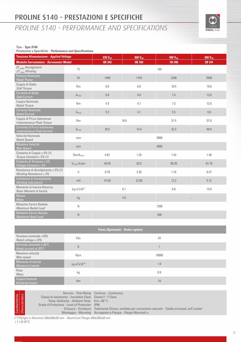
Tipo - Type S140 Prestazioni e Specifiche - Performance and Specifications
Tensione Alimentazione - Applied Voltage 230 VAC 400 VAC 400 VAC 400 VAC
Modello Servomotore - Servomotor Model 0B 343 0B 342 1B 340 2B 341
∆T MAX Avvolgimenti ∆T MAX Winding °C 105
Potenza Nominale Rated Power W 1400 1470 2200 3500
Coppia di Stallo Stall Torque Nm 6.0 6.0 10.5 19.0
Corrente di Stallo Stall Current Arms 6.8 4.8 7.4 13.6
Coppia Nominale Rated Torque Nm 4.5 4.7 7.3 12.0
Corrente Nominale Rated Current Arms 5.2 4.1 5.5 9.0
Coppia di Picco Istantanea Instantaneous Peak Torque Nm 18.0 31.5 57.0
Corrente di Picco Istantanea Instantaneous Peak Current Arms 20.5 14.4 22.2 40.8
Velocità Nominale Rated Speed rpm 3000
Massima Velocità Max Speed rpm 4000
Costante di Coppia ± 5% (1) Torque Constant ± 5% (1) Nm/Arms 0.87 1.25 1.42 1.40
Costante di Tensione ± 5% Voltage Constant ± 5% Vrms /krpm 49.50 82.8 90.20 87.70
Resistenza di Avvolgimento ± 5% (1) Winding Resistance ± 5% Ω 8.70 2.20 1.16 0.47
Induttanza di Avvolgimento Winding Inductance mH 47.00 22.00 12.3 5.12
Momento di Inerzia Rotorico Rotor Moment of Inertia kg·m2x10-4 6.1 8.8 15.0
Massa Mass kg 4.5 -
Massimo Carico Radiale Maximum Radial Load N 1200
Massimo Carico Assiale Maximum Axial Load N 500
Servizio - Time RatingClasse di Isolamento - Insulation Class
Temp. Ambiente - Ambient Temp.Grado di Protezione - Level of Protection
Chiusura - Enclosure Montaggio - Mounting
Continuo - ContinuousClasse F - F Class0 to +40° CIP65 Totalmente Chiuso, ventilato per convezione naturale - Totally enclosed, self cooled Accoppiato a Flangia - Flange Mounted (*)Ca
ratte
ristic
he
Char
acte
ristic
s
Freno (Opzionale) - Brake (option)
Tensione nominale ±10% Rated voltage ±10% Vdc 24
Corrente nominale a 20°CRated current at 20°C A 1
Massima velocitàMax speed Rpm 10000
Momento di inerziaMoment of inertia kg·m2x10-4 1.6
PesoMass kg 0.9
Coppia frenanteBreaking torque Nm 18
(*) Flangia in Alluminio 350x350x20 mm - Aluminium Flange 350x350x20 mm ( 1 ) @ 25°C

PROLINE S140 - PRESTAZIONI E SPECIFICHE
PROLINE S140 - PERFORMANCE AND SPECIFICATIONS
32
Caratteristiche Coppia/Velocità - Torque/Speed Characteristics
552
0
1000
2000
3000
4000
0 2 4 6 8 10 12 14 16 18 20
Coppia - Torque [Nm]
Vel
ocit
à - V
eloc
ity
[Rpm
]
554
0
1000
2000
3000
4000
0 4 8 12 16 20 24 28
Coppia - Torque [Nm]
Vel
ocit
à - V
eloc
ity
[Rpm
]
∆T = 105° C; Peak Torque
551
0
1000
2000
3000
4000
0 2 4 6 8 10 12 14 16 18 20
Coppia-Torque [Nm ]
Vel
ocit
à-V
eloc
ity
[ rpm
]
MOTORS 25
340
0
1000
2000
3000
4000
0 4 8 12 16 20 24 28 32 36 40
Coppia - Torque [Nm]
Vel
oci
tà -
Spe
ed [R
pm
]
Coppia - Torque [Nm]
Vel
oci
tà -
Spe
ed [
Rp
m]
Coppia - Torque [Nm]
Vel
oci
tà -
Spe
ed [
Rp
m]
Coppia - Torque [Nm]
Vel
oci
tà -
Spe
ed [R
pm
]
341
0
1000
2000
3000
4000
0 5 10 15 20 25 30 35 40 45 50 55 60
342
0
1000
2000
3000
4000
0 3 6 9 12 15 18 21 24 27 30
343
0
1000
2000
3000
4000
0 3 6 9 12 15 18 21 24 27 30
33
NOTE
NOTES

Direttive Europee e Standards - Motori Pro Line
European Directives and Standards - Pro Line Motors
34
DIRETTIVE
La Linea PRO LINE è conforme alle seguenti Direttive Europee:
• 2011/65/UE, RoHs II;• 2014/30/UE, Direttiva Compatibilità Elettromagnetica (EMC);• 2014/35/UE, Direttiva Bassa tensione (BT).
STANDARD
La conformità alle Direttive Europee è stata raggiunta facendo riferimento alle seguenti Norme armonizzate:
• CEI EN 50581: 2013-05, Documentazione tecnica per la valutazione dei prodotti elettrici ed elettronici in relazione alla restrizione delle sostanze pericolose;
• CEI EN 62474: 2013-02, Dichiarazione dei materiali per i prodotti di e per l’industria elettrotecnica;• CEI EN 61800-3: 2005-04, Azionamenti elettrici a velocità variabile, Parte 3: Requisiti di compatibilità elettromagnetica
e metodi di prova specifici;• CEI EN 61800-3/A1: 2013-09, Azionamenti elettrici a velocità variabile, Parte 3: Requisiti di compatibilità
elettromagnetica e metodi di prova specifici;• CEI EN 60034-1:2011-03, Macchine elettriche rotanti, Parte 1: Caratteristiche nominali e di funzionamento;• CEI EN 60034-1/EC: 2015-10, Macchine elettriche rotanti, Parte 1: Caratteristiche nominali e di funzionamento;• CEI EN 60034-2-1: 2015-01, Macchine elettriche rotanti, Parte 2-1: Metodi normalizzati per la documentazione
mediante prove delle perdite e de rendimento (escluse le macchine per veicoli di trazione);• CEI EN 60034-5: 2001-10, Macchine elettriche rotanti, Parte 5: Gradi di protezione degli involucri delle macchine
rotanti (Progetto integrale) (Codice IP) – Classificazione;• CEI EN 60034-5/A1: 2007-03, Macchine elettriche rotanti, Parte 5: Gradi di protezione degli involucri delle macchine
rotanti (Progetto integrale) (Codice IP) – Classificazione;• CEI EN 60034-6: 1997-09, Macchine elettriche rotanti, Parte 6: Metodi di raffreddamento (Codice IC);• CEI EN 60034-7: 1997-09, Macchine elettriche rotanti, Parte 7: Classificazione delle forme costruttive e dei tipi di
installazione (Codice IM);• CEI EN 60034-18-1: 2011-07, Macchine elettriche rotanti, Parte 18-1: Valutazione funzionale dei sistemi di isolamento
– Principi direttivi generali;• CEI EN 60034-18-21: 2014-02, Macchine elettriche rotanti, Parte 18-21: Valutazione funzionale dei sistemi di
isolamento – Procedure di prova per avvolgimenti a filo – Valutazione termica e classificazione;• CEI EN 60034-18-41: 2014-08, Macchine elettriche rotanti, Parte 18-41: Sistemi di Isolamento Elettrico Esenti da
Scariche Parziali (Tipo I) utilizzati in macchine elettriche rotanti alimentate da convertitori di tensione – Prove di qualificazione di controllo qualità;
• CEI TS 60034-27: 2012-01, Macchine elettriche rotanti, Parte 27: Misure fuori linea delle scariche parziali sull’isolamento dell’avvolgimento di statore di macchine elettriche rotanti;
• CEI EN 60270: 2002-06, Tecniche di prova in alta tensione, misure di scariche parziali;

35
DIRECTIVES
PRO LINE is compliant with the following European Directives:
• 2011/65/UE, RoHs II;• 2014/30/UE, Electromagnetic Compatibility (EMC);• 2014/35/UE, Low Voltage Directive (LV).
STANDARDS
Compliance with the European Directives has been achieved by adopting the following harmonised standards:
• CEI EN 50581: 2013-05, Technical documentation for the assessment of electrical and electronic products with respect to restriction of hazardous substances;
• CEI EN 62474: 2013-02, Material declaration for products of and for the electrotechnical industry;• CEI EN 61800-3: 2005-04, Adjustable speed electrical power drive systems, Part 3: EMC requirements and specific
test methods;• CEI EN 61800-3/A1: 2013-09, Adjustable speed electrical power drive systems, Part 3: EMC requirements and specific
test methods;• CEI EN 60034-1: 2011-03, Rotating electrical machines – Part 1: Rating and performance;• CEI EN 60034-1/EC: 2015-10, Rotating electrical machines – Part 1: Rating and performance;• CEI EN 60034-2-1: 2015-01, Rotating electrical machines – Part 2-1: standard methods for determining losses and
efficiency from tests (excluding machines for traction vehicles);• CEI EN 60034-5:2001-10, Rotating electrical machines – Part 5: Degrees of protection provided by the integral design
of rotating electrical machines (IP code) – Classification;• CEI EN 60034-5/A1: 2007-03, Rotating electrical machines – Part 5: Degrees of protection provided by the integral
design of rotating electrical machines (IP code) – Classification;• CEI EN 60034-6: 1997-09, Rotating electrical machines – Part 6: Methods of cooling (IC code);• CEI EN 60034-7: 1997-09, Rotating electrical machines – Part 7: Classification of types of constructions and mounting
arrangements (IM code);• CEI EN 60034-18-1: 2011-07, Rotating electrical machines – Part 18-1: Functional evaluation of insulation systems –
General guidelines;• CEI EN 60034-18-21: 2014-02, Rotating electrical machines – Part 18-21: Functional evaluation of insulation system –
Test procedures for wire-wound windings – Thermal evaluation and classification;• CEI EN 60034-18-41: 2014-08, Rotating electrical machines – Part 18-41: Partial discharge free electrical insulation
systems (Type I) used in rotating electrical machines fed from voltage converters – Qualification and quality control tests;
• CEI TS 60034-27: 2012-01, Rotating electrical machines – Part 27: Off-line partial discharge measurements on the stator winding insulation of rotating electrical machines;
• CEI EN 60270: 2002-06, High voltage test techniques, Partial discharge measurements;


100 Watt
MOTORIDUTTORE CON ELETTRONICA DIGITALE INTEGRATA
MOTORGEAR WITH INTEGRATED ELECTRONICS

PRO LAB ONE: INFORMAZIONI GENERALI
PRO LAB ONE: GENERAL INFORMATION
38
La soluzione PRO LAB ONE incorpora un riduttore integrato nel motore PRO LINE, fornibile in due versioni epicloidali, una con ingranaggeria sinterizzata, l’altra con ingranaggi tagliati a CNC, in una versione con rinvio angolare e in una versione con vite ipoide. Nella parte superiore del case alloggia un’elettronica digitale alimentata a 24Vdc, che opera con bus di campo CAN OPEN DS 402.
The PRO LAB ONE brings together in one solution an in-line planetary gear reducer (which can be made with either sintered gears or CNC machine cut gears, or have a straight, right angled or a hypoid reducer) with digital electronics housed above the motorgear. The rated voltage for both the power and the logic is 24Vdc whilst the fieldbus is CAN OPEN DS402.

39
PRO LAB ONE - SPECIFICHE DEL MOTORE
PRO LAB ONE - MOTOR SPECIFICATIONS
Motor Drive Specification Unit S0402B
Tensione di Alimentazione Applied Voltage (drive) Vdc 24
Potenza Nominale Rated Power W 100
Coppia di Stallo Stall Torque Nm 0.34
Coppia Nominale Rated Torque Nm 0.32
Corrente Nominale Rated Current Arms 6.5
Coppia Massima Peak Torque Nm 0.85
Corrente Massima Peak Current Arms 17
Velocità NominaleRated Speed rpm 3000
Velocità Massima Max Speed rpm 4000
Costante di Coppia Torque Constant Nm/A 0.05
Costante di Tensione Voltage Constant (phase to phase) Vrms/krpm 3.72
Temperatura Ambiente Ambient Temperature °C 0÷40
Classe di Isolamento Insulation Class - F
Grado IP IP Degree - 54
Classe di ServizioDuty Type - S1
Sensore di Posizione Feedback - Absolute Magnetic encoder single turn
Risoluzione Sensore Feedback Resolution (single turn) bit 12
(*) Flangia in Alluminio 250x250x6 mm - Aluminium Flange 250x250x6 mm
Servizio - Time RatingClasse di Isolamento - Insulation Class
Temp. Ambiente - Ambient Temp.Chiusura - Enclosure
Montaggio - Mounting
Continuo - ContinuousClasse F - F Class0 to +40° CTotalmente Chiuso, ventilato per convezione naturale - Totally enclosed, self cooled Accoppiato a Flangia - Flange Mounted (*)Ca
ratte
ristic
he
Char
acte
ristic
s
Caratteristiche Coppia/Velocità - Torque/Speed Characteristics
351
0
1000
2000
3000
4000
5000
0 0,25 0,5 0,75 1
Coppia - Torque [Nm]
Vel
ocit
à - S
peed
[Rpm
]
354
0
1000
2000
3000
4000
0 0,25 0,5 0,75 1
Coppia - Torque [Nm]
Vel
ocit
à - S
peed
[Rpm
]
353
0
1000
2000
3000
4000
5000
0 0,25 0,5 0,75 1
Coppia - Torque [Nm]
Vel
ocit
à - S
peed
[Rpm
]
∆T = 65° C; ∆T = 105° C; Peak Torque

40
PRO LAB ONE - CARATTERISTICHE DRIVE
PRO LAB ONE - DRIVE SPECIFICATIONS
CONNESSIONI - CONNECTIONS
Caratteristiche driveDrive specifications
DescrizioneDescription
Alimentazione logica Logic power supply 24Vdc, 80mA
Interfaccia di comunicazione Communication interface
CAN Open DS301/DS402MODBUS RTU
Analog Input 4-20mA
Modalità operativa Operating mode
HomingProfile Position modeProfile Velocity mode
Emulazione encoder Emulated encoder Programmable output pulses: 256-512-1024-2048
Interfaccia di servizio Service interface RS485 half duplex
Tipo connessioni Connection type 2xM12 5 pin - SUB D15
Selezione nodo Node ID selection Dip Switch
M12 TYPE A M12 TYPE B
1 Schermo 1 Schermo
2 Can 24V 2 Can 24V
3 Can GND 3 Can GND
4 Can_H 4 Can_H
5 Can_L 5 Can_L
D SUB HD DE 15
1 Enable Drive
2 Analog IN
3 GND
4 +24 Power
5 +24 Power
6 Drive OK (open drain)
7 NC
8 RS485 +
9 GND
10 +24 Logic
11 Encoder out (open drain)
12 Home In
13 RS 485 -
14 GND
15 +24 Power

XT - NXT: DIMENSIONI E TOLLERANZE
XT - NXT: DIMENSIONS AND TOLERANCES
Riduttori ingranaggi sinterizzati Sintered Gearbox
SimboliSymbols
UnitàUnit
1 stadio1 Stage
2 stadi2 Stage
Rapporto Ratio i - 4-8 16-25-32
Massima velocità in ingresso (1) Max input speed (1) n1 [rpm] 4000
Coppia continuativa max in uscita(2) Max output continuous torque (2) T2N [Nm] 4 5
Coppia accellerazione max in uscita(3) Max output starting torque (3) T2B [Nm] 8 8
Gioco angolare (4) Max backlash (4) jt [arcmin] <30
Efficienza Efficiency ɳd [%] 94 91
Forza radiale massima (5) Max output radial load (5) FR2 [N] 350
Forza assiale massima(5)
Max output axial load (5) FA2 [N] 200
Grado di protezione IP Degree IP - 54
Riduttori epicicloidaliPlanetary Gearbox
SimboliSymbols
UnitàUnit
1 stadio1 Stage
2 stadi2 Stage
Rapporto Ratio i - 4-9 16-25-35-63
Massima velocità in ingresso (1) Max input speed (1) n1 [rpm] 5000
Coppia continuativa max in uscita(2) Max output continuous torque (2) T2N [Nm] 9 9
Coppia accellerazione max in uscita(3) Max output starting torque (3) T2B [Nm] 17 17
Gioco angolare (4) Max backlash (4) jt [arcmin] <10 <12
Efficienza Efficiency ɳd [%] >96 >93
Forza radiale massima (5) Max output radial load (5) FR2 [N] 350
Forza assiale massima(5)
Max output axial load (5) FA2 [N] 200
Grado di protezione IP Degree IP - 54
(1) AtT2N e temperatura ambiente - At T2N and ambient temperature 20°C(2) Massima coppia conitnuativia per ciclo S1 - Max continuous torque for S1 duty(3) Massima coppia accellerazione per ciclo S5 - Max starting torque for S5 duty(4) Assenza lubrificanti, at 2%,di T2N - Without lubricant, at 2% of T2N
(5) Riferita a mezzeria albero di uscita con n2=100Rpm - Load applied in the middle of the output shaft, at n2=100rpm
41

NXTA: DIMENSIONI E TOLLERANZE
NXTA: DIMENSIONS AND TOLERANCES
(1) Massima coppia conitnuativia per ciclo S1 - Max continuous torque for S1 duty(2) Massima coppia accellerazione per ciclo S5 - Max starting torque for S5 duty(3) Assenza lubrificanti, at 2%,di T2N - Without lubricant, at 2% of T2N
(4) Riferita a mezzeria albero di uscita con n2=100Rpm - Load applied in the middle of the output shaft, at n2=100rpm
Riduttori Angolari Right Angle Gearbox
SimboliSymbols
UnitàUnit
1 stadio1 Stage
2 stadi2 Stage
Rapporto Ratio i - 4-9 16-25-35-63
Coppia continuativa massima in uscita (1) Max output continuous torque (1) T2N [Nm] 9
Coppia accelerazione max in uscita(2) Max output starting torque (2) T2B [Nm] 17
Gioco angolare(3)
Max backlash(3) jt [arcmin] <12 <15
Rendimento Efficiency ɳd [%] 88 84
Forza radiale massima(4) Max output radial load(4) FR2 [N] 350
Forza assiale massima(4) Max output axial load(4) FA2 [N] 200
Grado di protezioneIP Degree IP - 54
42

HY: DIMENSIONI E TOLLERANZE
HY: DIMENSIONS AND TOLERANCES
Riduttore IpoideHypoid Gearbox
SimboliSymbols
Unità di misuraUnit
1 stadio1 Stage
Rapporto Ratio i - 8
Velocità max in uscita (1) Max output speed (1) n1 [rpm] 500
Coppia continuativa max in uscita(2) Max output continuous torque (2) T2N [Nm] 2,5
Coppia accellerazione max in uscita(3) Max output starting torque (3) T2B [Nm] 5
Gioco angolare (4) Max backlash (4) jt [arcmin] <20
Rendimento Efficiency ɳd [%] 90
Forza radiale massima (5) Max output radial load (5) FR2 [N] 130
Forza assiale massima(5)
Max output axial load (5) FA2 [N] 50
Grado di protezione IP Degree IP - 54
(1) AtT2N e temperatura ambiente - At T2N and ambient temperature 20°C(2) Massima coppia conitnuativia per ciclo S1 - Max continuous torque for S1 duty(3) Massima coppia accellerazione per ciclo S5 - Max starting torque for S5 duty(4) Assenza lubrificanti, at 2%,di T2N - Without lubricant, at 2% of T2N
(5) Riferita a mezzeria albero di uscita con n2=100Rpm - Load applied in the middle of the output shaft, at n2=100rpm
DISPONIBILE IN CONFIGURAZIONE CON USCITA ALBERO A DESTRA O SINISTRAAVAILABLE WITH OUPUT SHAFT TO THE RIGHT OR THE LEFT
Versione SX - Version Left Versione DX – Version Right
43


200-400 Watt
MOTORIDUTTORE CON ELETTRONICA DIGITALE INTEGRATA
MOTORGEAR WITH INTEGRATED ELECTRONICS

PRO LAB FOUR: INFORMAZIONI GENERALI
PRO LAB FOUR: GENERAL INFORMATION
46
PRO LAB FOUR mantiene le caratteristiche di base del progetto PRO LAB ONE , sempre con elettronica integrata 4NXT, ma rende disponibili altre significative proprietà.• Possibilità di leggere l’encoder multigiro SINCOS HIPERFACE.• Oltre il CAN OPEN (DS 402) di base possiamo comunicare con bus di campo base Ethernet, come EtherCAT, ProfiNET
ed EtherNET IP.• Alimentazione a 48 Vdc per gestire una potenza fino a 400 WATT.• Possibilità di abbinamento con la nostra gamma di riduttori NXT GEAR.
PRO LAB FOUR with its 4NXT integrated electronics is a 48Vdc rated voltage, 400W rated power integrated motor which has the same basic features as PRO LAB ONE but significant additional features are available.• SINCOS HIPERFACE multi-turn encoder feedback option.• EtherCAT, ProfiNET and EtherNET fieldbus options CANopen (DS 402) is standard.• Can be coupled to our NXT Gear series.

PRO LAB FOUR - SPECIFICHE DEL MOTORE
PRO LAB FOUR - MOTOR SPECIFICATIONS
47
Motor Drive Specification Unit S060-1B S060-2B
Tensione di Alimentazione Applied Voltage (drive) Vdc 48
Potenza Nominale Rated Power W 200 400
Coppia di Stallo Stall Torque Nm 0.7 1.4
Coppia Nominale Rated Torque Nm 0.65 1.3
Corrente Nominale Rated Current Arms 6.8 13.3
Coppia Massima Peak Torque Nm 2.1 4.1
Corrente Massima Peak Current Arms 21 40
Velocità NominaleRated Speed rpm 3000
Velocità Massima Max Speed rpm 5000
Costante di Coppia Torque Constant Nm/A 0.1 0.1
Costante di Tensione Voltage Constant (phase to phase) Vrms/krpm 5.8
Temperatura Ambiente Ambient Temperature °C 0÷40
Classe di Isolamento Insulation Class - F
Grado IP IP Degree - 65
Classe di ServizioDuty Type - S1
Sensore di Posizione Feedback - Absolute Magnetic encoder single turn; Hyperface absolute multiturn encoder
Risoluzione Sensore Feedback Resolution (single turn) bit 12 single turn + 12 multiturn
Momento di Inerzia Rotorico Rotor Moment of Inertia kg·m2x10-4 0.19 0.30
MassaMass kg 2.3
Massimo Carico RadialeMaximum Radial Load N 250
Massimo Carico AssialeMaximum Axial Load N 80
Freno (Opzionale) - Brake (option)
Tensione nominale ±10% Rated voltage ±10% Vdc 24
Corrente nominale a 20°CRated current at 20°C A 0.46
Massima velocitàMax speed Rpm 10000
Momento di inerziaMoment of inertia kg·m2x10-4 0,068
PesoMass kg 0.15
Coppia frenanteBreaking torque Nm 2
(*) Flangia in Alluminio 250x250x6 mm - Aluminium Flange 250x250x6 mm
Servizio - Time RatingClasse di Isolamento - Insulation Class
Temp. Ambiente - Ambient Temp.Chiusura - Enclosure
Montaggio - Mounting
Continuo - ContinuousClasse F - F Class0 to +40° CTotalmente Chiuso, ventilato per convezione naturale - Totally enclosed, self cooled Accoppiato a Flangia - Flange Mounted (*)Ca
ratte
ristic
he
Char
acte
ristic
s

Caratteristiche Coppia/Velocità - Torque/Speed Characteristics
ΔT = 105° C Peak Torque
0
1000
2000
3000
4000
5000
0 0.5 1 1.5 2 2.5 3
Velo
cità
-Ve
locity
[Rpm
]
Coppia - Torque [Nm]
1B
0
1000
2000
3000
4000
5000
0 1 2 3 4 5 6
Velo
cità
-Ve
locity
[Rpm
]
Coppia - Torque [Nm]
2B
Caratteristiche Coppia/Velocità - Torque/Speed Characteristics
ΔT = 105° C Peak Torque
0
1000
2000
3000
4000
5000
0 0.5 1 1.5 2 2.5 3
Velo
cità
-Ve
locity
[Rpm
]
Coppia - Torque [Nm]
1B
0
1000
2000
3000
4000
5000
0 1 2 3 4 5 6
Velo
cità
-Ve
locity
[Rpm
]
Coppia - Torque [Nm]
2B
Caratteristiche Coppia/Velocità - Torque/Speed Characteristics
ΔT = 105° C Peak Torque
0
1000
2000
3000
4000
5000
0 0.5 1 1.5 2 2.5 3
Velo
cità
-Ve
locity
[Rpm
]
Coppia - Torque [Nm]
1B
0
1000
2000
3000
4000
5000
0 1 2 3 4 5 6
Velo
cità
-Ve
locity
[Rpm
]
Coppia - Torque [Nm]
2B
PRO LAB FOUR - SPECIFICHE DEL MOTORE
PRO LAB FOUR - MOTOR SPECIFICATIONS
48
CARATTERISTICHE DRIVE
DRIVE SPECIFICATIONS
Caratteristiche driveDrive specifications
DescrizioneDescription
Alimentazione logica Logic power supply 24Vdc, 80mA
Interfaccia di comunicazione integrata Integrated communication interface
CANopen DS301/DS402MODBUS RTU
Analog Input 4-20mA
Interfaccia di comunicazione opzionale Optional communication interface
EtherCATProfiNET
Ethernet/IP
Modalità operativaOperating mode
HomingProfile Position mode - Profile Velocity mode
Torque profile mode - Interpolation modeEmulazione encoder Emulated encoder Programmable output pulses: 256-512-1024-2048
Interfaccia di servizio Service interface RS485 - USB
Tipo connessioni Connection type M15 15 pin - M15 12 pin
Selezione nodoNode ID selection Dip Switch
Resistenza di frenatura Braking resistor Running also without power supply
Funzione di sicurezza integrataIntegrated safety function STO SIL2

49
PROLAB FOUR - DIMENSIONI E TOLLERANZE
PROLAB FOUR - DIMENSIONS AND TOLERANCES
CONNESSIONI
CONNECTIONS
M12 TYPE A M12 TYPE B
1 Schermo 1 Schermo
2 Can 24V 2 Can 24V
3 Can GND 3 Can GND
4 Can_H 4 Can_H
5 Can_L 5 Can_L
ETHERCAT M12 CONNECTOR
1 Transmit + (TD+)
2 Receive + (RD+)
3 Transmit - (TD-)
4 Receive - (RD-)

50
PRO LAB FOUR - ALTRE CONNESSIONI
PRO LAB FOUR - OTHER CONNECTIONS
Alimentazione di potenza e segnali STO (Comandi e diagnostica) - Power supply and STO signal (control and diagnostic)
1 48V (1.5mm²)
2 GND(1.5mm²)
3 GND(1.5mm²)
4 24V(0.75mm²)
5 STOA+
6 STOA-
7 STOB+
8 STOB-
9 Diagnostica STOA 24V - STOA 24V Diagnostic
10 Diagnostica STOA OUT- STOA OUT Diagnostic
11 Diagnostica STOB 24V- STOB 24V Diagnostic
12 Diagnostica STOB OUT- STOB OUT Diagnostic
13 Diagnostica EN 24V- EN 24V Diagnostic
14 Diagnostica EN OUT- EN OUT Diagnostic
15 Diagnostica GND- GND Diagnostic
Connettore I/O digitali e Analogici - Digital and analog I/O connector
1 24V OUT
2 Analog IN
3 Enable
4 Homing sensor IN
5 Drive Ok OUT (open drain)
6 Encoder OUT (open drain)
7 RS485+
8 RS485-
9 Rilevamento Pulsantiera - Button Panel Sensing
10 Senso di rotazione /IN1DS402 - Rotation Direction Sensing /IN1DS402
11 Jog /IN2DS402
12 GND

51
NOTE
NOTES

Direttive Europee e Standards - Drive Pro Lab
European Directives and Standards - Drive Pro Lab
52
DIRETTIVE
La Linea PRO LAB è conforme alle seguenti Direttive Europee:
• 2006/42/CE: Macchine e Quasi-Macchine;• 2011/65/UE, RoHs II;• 2014/30/UE, Direttiva Compatibilità Elettromagnetica (EMC);
STANDARD
La conformità alle Direttive Europee è stata raggiunta facendo riferimento alle seguenti Norme armonizzate:
• CEI EN 50581: 2013-05, Documentazione tecnica per la valutazione dei prodotti elettrici ed elettronici in relazione alla restrizione delle sostanze pericolose;
• CEI EN 62474: 2013-02, Dichiarazione dei materiali per i prodotti di e per l’industria elettrotecnica;• CEI EN 60529: 1997-06: Gradi di protezione degli involucri (Codice IP);• CEI EN 61800-3: 2005-04, Azionamenti elettrici a velocità variabile, Parte 3: Requisiti di compatibilità elettromagnetica
e metodi di prova specifici;• CEI EN 61800-3/A1: 2013-09, Azionamenti elettrici a velocità variabile, Parte 3: Requisiti di compatibilità
elettromagnetica e metodi di prova specifici;• CEI EN 61800-5-1: 2009-04, Azionamenti elettrici a velocità variabile Parte 5-1: Prescrizioni di sicurezza - Sicurezza
elettrica, termica ed energetica;• CEI EN 61800-5-2: 2009-4, Azionamenti elettrici a velocità variabile. Part 5-2: Prescrizioni di sicurezza - Sicurezza
Funzionale;• CEI EN 60034-1:2013-11: Macchine elettriche rotanti, Parte 1: Caratteristiche nominali e di funzionamento• CEI EN 60034-1/EC: 2015-10, Macchine elettriche rotanti, Parte 1: Caratteristiche nominali e di funzionamento;• CEI EN 60034-5: 2001-10, Macchine elettriche rotanti, Parte 5: Gradi di protezione degli involucri delle macchine
rotanti (Progetto integrale) (Codice IP) – Classificazione;• CEI EN 60034-5/A1: 2007-03, Macchine elettriche rotanti, Parte 5: Gradi di protezione degli involucri delle macchine
rotanti (Progetto integrale) (Codice IP) – Classificazione;• CEI EN 60034-6: 1997-09, Macchine elettriche rotanti, Parte 6: Metodi di raffreddamento (Codice IC);• CEI CLC\ TS 60034-25: 2010-06, Macchine elettriche rotanti, Parte 25: Guida per la progettazione e le prestazioni dei
motori in corrente alternata specificamente progettati per l’alimentazione da convertitori

53
DIRECTIVES
PRO LAB is compliant with the following European Directives:
• 2006/42/CE, machinery and partly completed machinery;• 2011/65/UE, RoHs II;• 2014/30/UE, Electromagnetic Compatibility (EMC).
STANDARDS
Compliance with the European Directives has been achieved by adopting the following harmonised standards:
• CEI EN 50581: 2013-05, Technical documentation for the assessment of electrical and electronic products with respect to restriction of hazardous substances;
• CEI EN 62474: 2013-02, Material declaration for products of and for the electrotechnical industry;• CEI EN 60529: 1997-06: Degrees of protection provided by enclosures (IP Code)• CEI EN 61800-3: 2005-04, Adjustable speed electrical power drive systems, Part 3: EMC requirements and specific
test methods;• CEI EN 61800-3/A1: 2013-09, Adjustable speed electrical power drive systems, Part 3: EMC requirements and specific
test methods;• CEI EN 61800-5-1: 2009-04, Adjustable speed electrical power drive systems. Part 5-1: Safety requirements –electrical,
thermal and energy;• CEI EN 61800-5-2: 2009-4, Adjustable speed electrical power drive systems. Part 5-2: Safety Requirements – Functional;• CEI EN 60034-1: 2011-03, Rotating electrical machines – Part 1: Rating and performance;• CEI EN 60034-1/EC: 2015-10, Rotating electrical machines – Part 1: Rating and performance;• CEI EN 60034-5:2001-10, Rotating electrical machines – Part 5: Degrees of protection provided by the integral design
of rotating electrical machines (IP code) – Classification;• CEI EN 60034-5/A1: 2007-03, Rotating electrical machines – Part 5: Degrees of protection provided by the integral
design of rotating electrical machines (IP code) – Classification;• CEI EN 60034-6: 1997-09, Rotating electrical machines – Part 6: Methods of cooling (IC code);• CEI CLC\ TS 60034-25:2010-06, Rotating Electrical Machines, Part 25: Guidance for the design and performance of a.c.
motors specifically designed for converter supply.

NOTE
NOTES

Per informazioni tecniche / For technical information
SIBONI S.r.l.Via Lughese, 161/a
47122 - San Martino in Villafranca (FC)Tel.: +39 (0)543 764890Fax: +39 (0)543 764218
E-mail: [email protected]
Siboni S.r.l. si riserva tutti i diritti di proprietà intellettuale del presente documento. È vietata la copia e la diffusione anche parziale, senza previa autorizzazione scritta.
Siboni S.r.l. si riserva il diritto di apportare modifiche senza preavviso.Sostituisce tutte le versioni precedenti con revisione inferiore.
Siboni S.r.l. reserves the rights to the intellectual property of this document. The disclosure and copying of it, even in part, is expressly forbidden without prior written consent.
Siboni S.r.l. reserves the right to modify the products without prior notice.This version replaces all previous versions with a lower revision.

56
www.siboni.it
ITA - ENG
MOTORS
11 -
201
7


![Riduttori per Servomotori - RS & RT 28 - ATTI srl · - 12 - Riduttori per Servomotori - RS & RT Selezione RS RT i 2accT [Nm] T2ISO [Nm] T2max [Nm] n 1 [rpm] n1max [rpm] [arcmin]Ct](https://static.fdocuments.net/doc/165x107/5f143d4e9680b36af56f47a5/riduttori-per-servomotori-rs-rt-28-atti-srl-12-riduttori-per-servomotori.jpg)