Service Manual - Monster Scooter...
27
Service Manual MOBY XL, SE-803 40cc PowerBoard Date 09-16-02 ISM, Inc. 1028 4 th Street SW Auburn, WA 98001 Phone: (253) 333-1200 Fax: (253) 333-1212 www.tanaka-usa.com [email protected] Revision 001
Transcript of Service Manual - Monster Scooter...

Service ManualMOBY XL, SE-80340cc PowerBoard Date 09-16-02
ISM, Inc. 1028 4th Street SW Auburn, WA 98001 Phone: (253) 333-1200 Fax: (253) 333-1212
www.tanaka-usa.com [email protected]
Revision 001
www.tanaka-usa.com [email protected]
Service Manual Moby XL, SE-803
Table of Contents
Specifications 1 Torque Limits 1 Troubleshooting 2-3 Safety & Shop Practices 4 Routine Maintenance 4 Tools 5 General Inspection 6-8 Engine Repair 9-16 Brake System 17 Wheel Removal 18-19 Steering Head Components 20 Cables / Controls 21 Belt Adjustment / Replacement 22-23 Deck Removal 24 Warranty Statement 25

www.tanaka-usa.com 1 [email protected]
Service Manual Moby XL, SE-803
Specification Chart
Cylinder Plating Chrome
Piston Rings 2 Displacement (cc) 39.8
Horsepower 1.8 Bore x Stroke (mm) 39.8 x 32 Compression ratio 7.2:1
Maximum hp 1.8 @ 7500 rpm Maximum kw 1.14 @ 8000 rpm
Maximum torque – kg-m (ft. lbs) 0.21 (1.5) @ 5500 rpm Maximum RPM 11000
Idling RPM 3000 +/- 200 Starting System Recoil
Rotation (recoil side) Clockwise Fuel capacity – cc (fl. oz) 1000 (33.8)
Fuel consumption – g/hp.hr (g/kw.hr) 345 (469) Carburetor WYJ-224, Walbro
Clutch Diameter 76 mm Spark Plug CJ7 (Champion) / BM7A (NGK)
Ignition System TCI Spark Plug Electrode Gap .024 Second Coil Resistance 5.8 KΩ
Coil Air Gap .014 / .016 Engine Dimensions – LxWxH (mm) 170 x 260 x 270
Engine Weight – kg (lbs) 3.9 (8.6) Scooter Weight 52 lbs. Overall Length 48”
Height / (folded) 40” (17”) Maximum Speed 24/25mph
Drive Ratio 10:1 Tire Air Pressure 50 psi (max)
Brakes (Front) Disc Brakes (Rear) Friction
Tire Size / Type 10”/4 ply Weight Capacity 270 lbs.
Fuel Gas/Oil 50:1 Spark Plug BPM6A (or equiv.)
Drive System Dual Belt Ground Clearance 4.5”
Torque Limits
In. - Lb. N - M Crankcase 40 4.5 Cylinder 40 4.5 Carburetor Insulator 45 5.0 Carburetor 38 4.2 Clutch Shoes 200 22.5 Flywheel 185 20.8 Ignition Coil 25 2.8 Spark Plug 150 16.8 Pawl Carrier 25 2.8 Fan Case 35 3.9 Muffler 50 5.6

www.tanaka-usa.com 2 [email protected]
Service Manual Moby XL, SE-803
Trouble Shooting
Engine Idles Poorly Check Function of: Page No. Clutch System ……………………….9 Ignition System: Spark Plug …………………….7, 8 Ignition System: Poor Spark ………………8, 11, 12 Fuel System : Fuel Tank …………...6, 8, 12, 13 Fuel System : Carburetor ………….7, 12, 13, 14 Air Filter ……………………….6 Exhaust System ………………7, 14, 15 Compression ……………………….7 Engine Lacks Power Check Function of: Page No. Clutch System ……………………….9 Ignition System: Poor Spark ………………8, 11, 12 Fuel System : Fuel Tank …………...6, 8, 12, 13 Fuel System : Carburetor ………….7, 12, 13, 14 Air Filter ……………………….6 Exhaust System ………………7, 14, 15 Compression ……………………….7 Engine Stops Suddenly Check Function of: Page No. Ignition System: No Spark …………...7, 8, 11, 12 Fuel System : Fuel Tank …………...6, 8, 12, 13 Fuel System : Carburetor ………………8, 12, 13 Compression ……………………….7
(Trouble Shooting cont.)
Engine Will Not Start Check Function of: Page No. Rewind Starter ………………6, 10, 11 Ignition System: No Spark …………...7, 8, 11, 12 Fuel System : Fuel Tank …………...6, 8, 12, 13 Fuel System : Carburetor ………………8, 12, 13 Air Filter ……………………….6 Exhaust System ………………7, 14, 15 Compression ……………………….7

www.tanaka-usa.com 3 [email protected]
Service Manual Moby XL, SE-803
Trouble Shooting cont.
Scooter vibrates
Check Function of: Page No: Engine: …see page 2 Wheels: ………….………….6,7 Drive train: ………….………….8,9 Engine does not shut off with kill button
Check Function of: Page No: Engine: …see page 2 Cables / Controls: …………………….…8 Scooter does not adequately stop
Check Function of: Page No:
Brakes: ……………………….6
Scooter lacks power / acceleration Check Function of: Page No: Engine: …see page 2 Brakes: ………….……………6 Wheels: ………….……………6 Cables / Controls: …………………….…8 Drive train: ……………………..8,9
www.tanaka-usa.com 4 [email protected]
Service Manual Moby XL, SE-803
Safety & Shop Practices
o The most successful and profitable service shops consistently seem to maintain the best habits of safety, cleanliness, and orderly procedure. The following information is intended as a guide towards developing habits that are necessary to accomplish satisfactory service work.
o Maintain a clean and orderly work area that is well lighted and adequately ventilated.
o Tools, instruments, and parts needed for work should be clean and readily available before any job is started.
(Special tools available for servicing TANAKA equipment are listed in this manual.)
o Scooter should be cleaned before repair work starts. Cleaning will often help reveal a source of trouble.
o Before attempting to repair or operate any equipment, read and understand all information provided by the instruction manual for the equipment.
o Never attempt to service a unit that is running or still heated from running unless it is specifically required by the
manufacturer’s instructions.
o Wipe-up all spilled liquids immediately. Use non-flammable solvents for cleaning. Clean all parts before reconditioning or reassembling.
o Thoroughly inspect all parts for wear or damage. Replace all parts that show damage or excessive wear.
o Always recondition and /or repair equipment strictly according to the Manufacturer’s specifications.
o Be sure all shields and safety devices are correctly installed before performing any final operating tests.
o After completion of any service or repair, the equipment should be thoroughly cleaned.
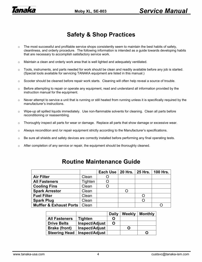
Routine Maintenance Guide
Each Use 20 Hrs. 25 Hrs. 100 Hrs. Air Filter Clean O All Fasteners Tighten O Cooling Fins Clean O Spark Arrestor Clean O Fuel Filter Clean O Spark Plug Clean O Muffler & Exhaust Ports Clean O
Daily Weekly Monthly All Fasteners Tighten O Drive Belts Inspect/Adjust O Brake (front) Inspect/Adjust O Steering Head Inspect/Adjust O
www.tanaka-usa.com 5 [email protected]
Moby XL. SE-803 Service Manual
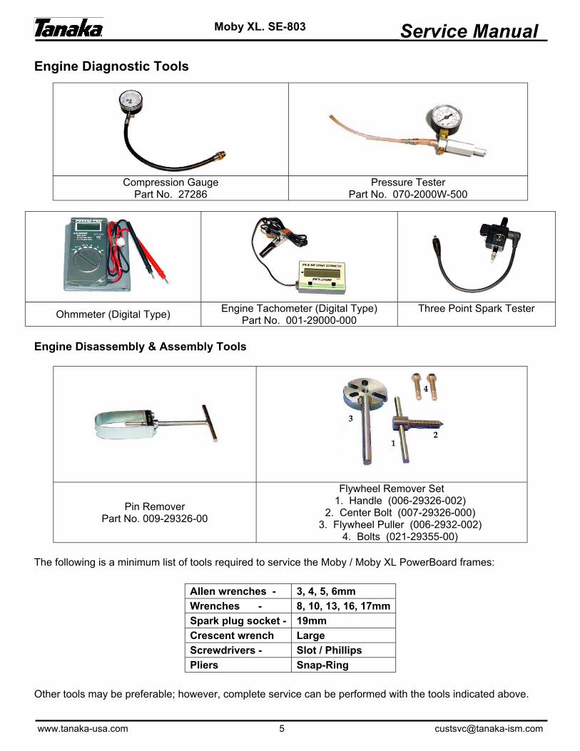
Engine Diagnostic Tools
Engine Disassembly & Assembly Tools
Pin Remover Part No. 009-29326-00
Flywheel Remover Set 1. Handle (006-29326-002)
2. Center Bolt (007-29326-000) 3. Flywheel Puller (006-2932-002)
4. Bolts (021-29355-00) The following is a minimum list of tools required to service the Moby / Moby XL PowerBoard frames:
Allen wrenches - 3, 4, 5, 6mm Wrenches - 8, 10, 13, 16, 17mm Spark plug socket - 19mm Crescent wrench Large Screwdrivers - Slot / Phillips Pliers Snap-Ring
Other tools may be preferable; however, complete service can be performed with the tools indicated above.
Compression Gauge
Part No. 27286 Pressure Tester
Part No. 070-2000W-500
Ohmmeter (Digital Type) Engine Tachometer (Digital Type)
Part No. 001-29000-000 Three Point Spark Tester
www.tanaka-usa.com 6 [email protected]
Service Manual Moby XL, SE-803
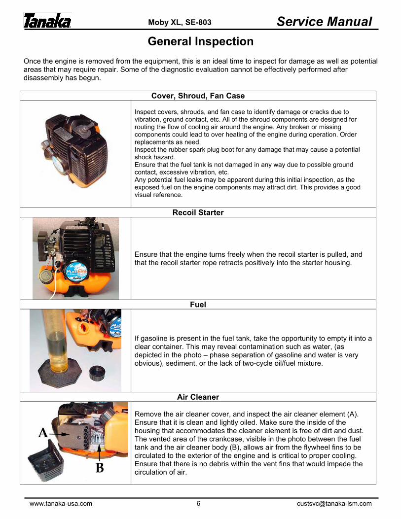
General Inspection Once the engine is removed from the equipment, this is an ideal time to inspect for damage as well as potential areas that may require repair. Some of the diagnostic evaluation cannot be effectively performed after disassembly has begun.
Cover, Shroud, Fan Case
Inspect covers, shrouds, and fan case to identify damage or cracks due to vibration, ground contact, etc. All of the shroud components are designed for routing the flow of cooling air around the engine. Any broken or missing components could lead to over heating of the engine during operation. Order replacements as need. Inspect the rubber spark plug boot for any damage that may cause a potential shock hazard. Ensure that the fuel tank is not damaged in any way due to possible ground contact, excessive vibration, etc. Any potential fuel leaks may be apparent during this initial inspection, as the exposed fuel on the engine components may attract dirt. This provides a good visual reference.
Recoil Starter
Ensure that the engine turns freely when the recoil starter is pulled, and that the recoil starter rope retracts positively into the starter housing.
Fuel
If gasoline is present in the fuel tank, take the opportunity to empty it into a clear container. This may reveal contamination such as water, (as depicted in the photo – phase separation of gasoline and water is very obvious), sediment, or the lack of two-cycle oil/fuel mixture.
Air Cleaner
Remove the air cleaner cover, and inspect the air cleaner element (A). Ensure that it is clean and lightly oiled. Make sure the inside of the housing that accommodates the cleaner element is free of dirt and dust. The vented area of the crankcase, visible in the photo between the fuel tank and the air cleaner body (B), allows air from the flywheel fins to be circulated to the exterior of the engine and is critical to proper cooling. Ensure that there is no debris within the vent fins that would impede the circulation of air.
www.tanaka-usa.com 7 [email protected]
Service Manual Moby XL, SE-803
General Inspection Cont.
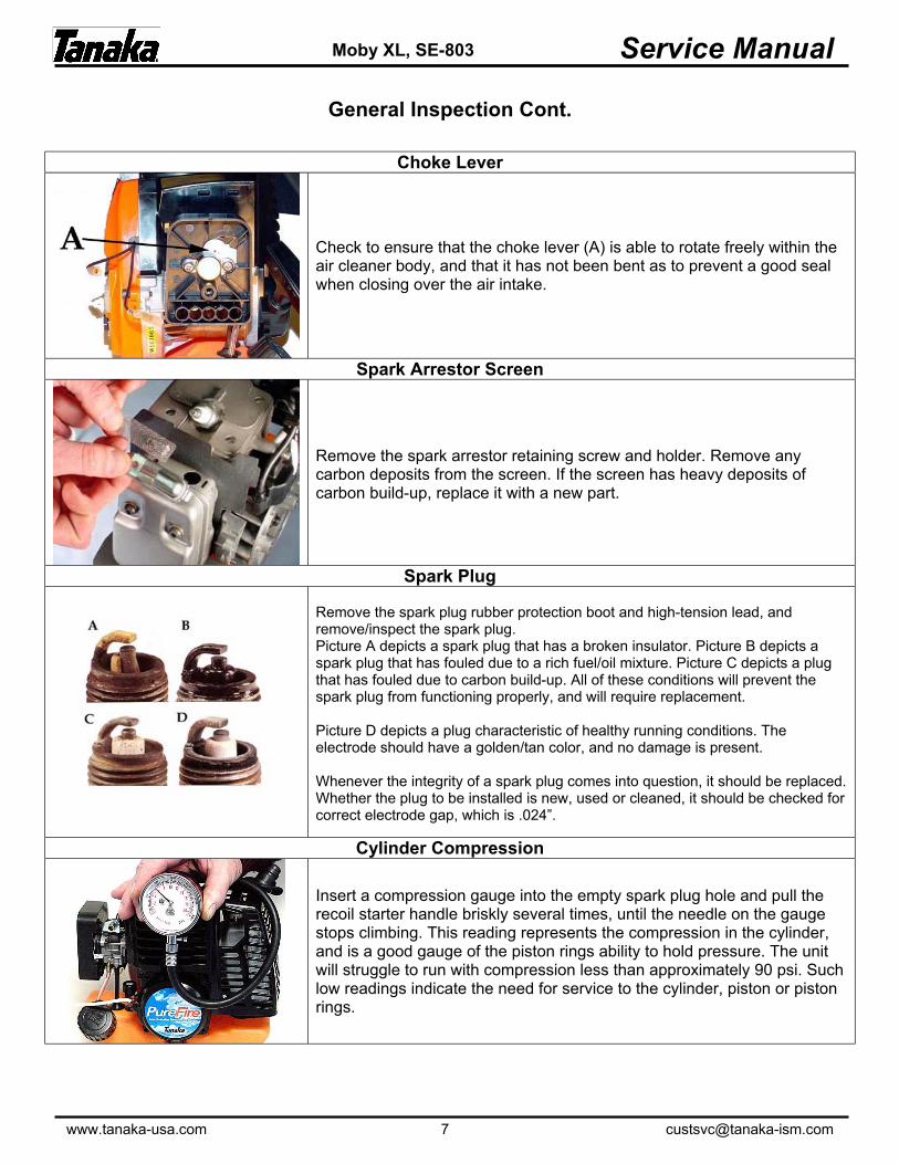
Choke Lever
Check to ensure that the choke lever (A) is able to rotate freely within the air cleaner body, and that it has not been bent as to prevent a good seal when closing over the air intake.
Spark Arrestor Screen
Remove the spark arrestor retaining screw and holder. Remove any carbon deposits from the screen. If the screen has heavy deposits of carbon build-up, replace it with a new part.
Spark Plug
Remove the spark plug rubber protection boot and high-tension lead, and remove/inspect the spark plug. Picture A depicts a spark plug that has a broken insulator. Picture B depicts a spark plug that has fouled due to a rich fuel/oil mixture. Picture C depicts a plug that has fouled due to carbon build-up. All of these conditions will prevent the spark plug from functioning properly, and will require replacement. Picture D depicts a plug characteristic of healthy running conditions. The electrode should have a golden/tan color, and no damage is present. Whenever the integrity of a spark plug comes into question, it should be replaced. Whether the plug to be installed is new, used or cleaned, it should be checked for correct electrode gap, which is .024”.
Cylinder Compression
Insert a compression gauge into the empty spark plug hole and pull the recoil starter handle briskly several times, until the needle on the gauge stops climbing. This reading represents the compression in the cylinder, and is a good gauge of the piston rings ability to hold pressure. The unit will struggle to run with compression less than approximately 90 psi. Such low readings indicate the need for service to the cylinder, piston or piston rings.

www.tanaka-usa.com 8 [email protected]
Service Manual Moby XL, SE-803
General Inspection Cont.
Spark Testing
While the rubber spark plug boot / high-tension lead are removed from the spark plug, this is an ideal time to test the quality of the current being delivered to the spark plug. Insert a three point spark tester into the spark plug boot and briskly pull the recoil starter. The tester should reveal a strong spark with a blue color. Lack of spark, weak spark, or yellow spark may indicate a problem with another electrical component within the engine.
Ignition Coil Testing
Connect an ohmmeter to the ignition coil with one lead inserted into the spark plug boot and the other making contact with the cylinder fins of the engine (as shown). Secondary resistance, when tested this way, should indicate 5.8 (+/- 1) KΩ. If the reading is not within this range, replace with a new coil, (previous tests for spark using a three point tester should have indicated a weak spark or none at all). If the reading is within range, and still weak or no spark is evident, replace the ignition coil.
Fasteners
Check to ensure that all fasteners are tight prior to disassembly. Loosening of fasteners on the carburetor side may cause erratic running conditions, or even engine failure. It’s always best to know if fasteners are properly torqued prior to engine service, as problematic running conditions may be the result.
Fuel Filter
Using a hooked wire, reach into the filler neck of the fuel tank, and grasp the fuel line. Gently pull the fuel line, with the fuel filter attached, through the filler neck. The filter should be white in color and should be compressible between two fingers. If it appears discolored or hard, replace with a new one.

www.tanaka-usa.com 9 [email protected]
Service Manual Moby XL, SE-803
Engine Repair
ENGINE SERVICE
Troubleshooting should alert you to problem areas, and these problem areas can be addressed as major sub-components of the engine:
• Centrifugal Clutch • Recoil Starter • Electrical System • Fuel System Components • Exhaust System • Crank Case
It is important to properly identify which areas of the engine require service to avoid any unnecessary tear down of components not requiring service.
CLUTCH SYSTEM CAUTION: Never attempt to run the engine with the clutch exposed. The clutch is designed to overcome the force of the spring, thus allowing contact with the clutch drum, ultimately providing drive to the PTO side of the equipment. If the clutch is not contained within the clutch drum while the engine is running, the clutch components may come detached from the engine and pose a risk of flying objects.
The clutch system is made up of the clutch shoes, clutch spring, and the bolts and washers (flat and waved) securing them to the flywheel.
Using an impact wrench or a sharp blow to a socket wrench, remove the bolts securing the clutch to the flywheel (right hand threaded, counter-clockwise for removal.) This will enable all of the components to be inspected. Check for any signs of damage to clutch shoes or excessive wear on the lining of the shoes. When new, the shoes have approximately two millimeters of lining. Order spares as needed. Inspect the wave washers mounted between the bolt and the clutch shoes to ensure that they are not cracked and still provide spring tension. Ensure that the spring is not cracked or broken. Replace as needed. When re-installing the clutch components, attach the spring between the shoes then add the bolts with the wave washers. Hold in place with the flat washers between the backside of the clutch arms and the flywheel, and tighten the stepped bolts to 185 in.-lbs.
www.tanaka-usa.com 10 [email protected]
Service Manual Moby XL, SE-803
Engine Repair Cont.
RECOIL STARTER
CAUTION: The recoil spring is wound with significant force. When removed from the starter body, it will rapidly unwind. It is recommended that you wear gloves and eye protection when removing the starter spring.
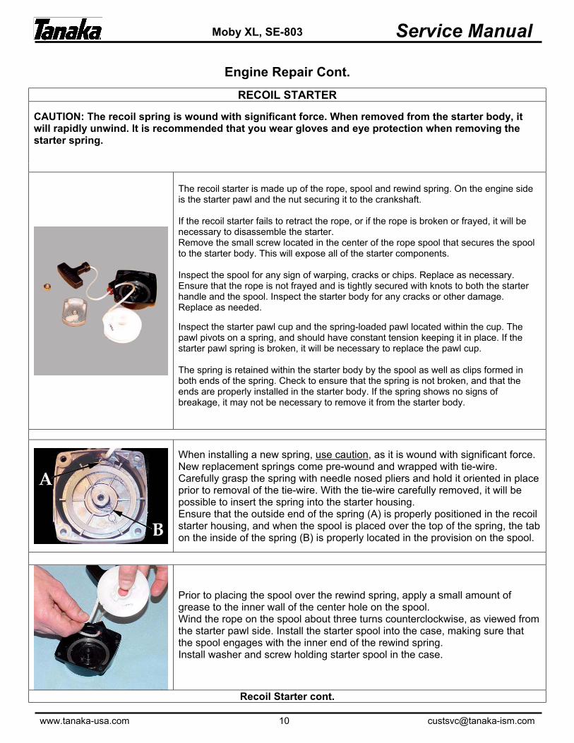
The recoil starter is made up of the rope, spool and rewind spring. On the engine side is the starter pawl and the nut securing it to the crankshaft. If the recoil starter fails to retract the rope, or if the rope is broken or frayed, it will be necessary to disassemble the starter. Remove the small screw located in the center of the rope spool that secures the spool to the starter body. This will expose all of the starter components. Inspect the spool for any sign of warping, cracks or chips. Replace as necessary. Ensure that the rope is not frayed and is tightly secured with knots to both the starter handle and the spool. Inspect the starter body for any cracks or other damage. Replace as needed. Inspect the starter pawl cup and the spring-loaded pawl located within the cup. The pawl pivots on a spring, and should have constant tension keeping it in place. If the starter pawl spring is broken, it will be necessary to replace the pawl cup. The spring is retained within the starter body by the spool as well as clips formed in both ends of the spring. Check to ensure that the spring is not broken, and that the ends are properly installed in the starter body. If the spring shows no signs of breakage, it may not be necessary to remove it from the starter body.
When installing a new spring, use caution, as it is wound with significant force. New replacement springs come pre-wound and wrapped with tie-wire. Carefully grasp the spring with needle nosed pliers and hold it oriented in place prior to removal of the tie-wire. With the tie-wire carefully removed, it will be possible to insert the spring into the starter housing. Ensure that the outside end of the spring (A) is properly positioned in the recoil starter housing, and when the spool is placed over the top of the spring, the tab on the inside of the spring (B) is properly located in the provision on the spool.
Prior to placing the spool over the rewind spring, apply a small amount of grease to the inner wall of the center hole on the spool. Wind the rope on the spool about three turns counterclockwise, as viewed from the starter pawl side. Install the starter spool into the case, making sure that the spool engages with the inner end of the rewind spring. Install washer and screw holding starter spool in the case.
Recoil Starter cont.
www.tanaka-usa.com 11 [email protected]
Service Manual Moby XL, SE-803
Engine Repair Cont.
Recoil Starter cont.
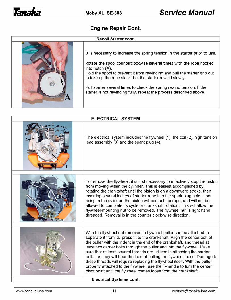
It is necessary to increase the spring tension in the starter prior to use. Rotate the spool counterclockwise several times with the rope hooked into notch (A). Hold the spool to prevent it from rewinding and pull the starter grip out to take up the rope slack. Let the starter rewind slowly. Pull starter several times to check the spring rewind tension. If the starter is not rewinding fully, repeat the process described above.
ELECTRICAL SYSTEM
The electrical system includes the flywheel (1), the coil (2), high tension lead assembly (3) and the spark plug (4).
To remove the flywheel, it is first necessary to effectively stop the piston from moving within the cylinder. This is easiest accomplished by rotating the crankshaft until the piston is on a downward stroke, then inserting several inches of starter rope into the spark plug hole. Upon rising in the cylinder, the piston will contact the rope, and will not be allowed to complete its cycle or crankshaft rotation. This will allow the flywheel-mounting nut to be removed. The flywheel nut is right hand threaded. Removal is in the counter clock-wise direction.
With the flywheel nut removed, a flywheel puller can be attached to separate it from its’ press fit to the crankshaft. Align the center bolt of the puller with the indent in the end of the crankshaft, and thread at least two carrier bolts through the puller and into the flywheel. Make sure that at least several threads are utilized in attaching the carrier bolts, as they will bear the load of pulling the flywheel loose. Damage to these threads will require replacing the flywheel itself. With the puller properly attached to the flywheel, use the T-handle to turn the center pivot point until the flywheel comes loose from the crankshaft.
Electrical Systems cont.

www.tanaka-usa.com 12 [email protected]
Service Manual Moby XL, SE-803
Engine Repair Cont.
Electrical Systems cont.
Remove the flywheel (refer to page 11 for disassembly procedure), and inspect the integrity of the flywheel keyway, the crankshaft keyway and the key itself. Any deformation of the key or keyways will require replacement of those components.
After identifying the integrity of the coil (refer to page 8 for coil testing procedure), or replacing it with a new one, check the air gap between the coil and flywheel (A). Gap should be measured with a feeler gauge and set at 0.014”.
FUEL SYSTEM
The fuel system consists of the carburetor (1), fuel tank (2), fuel supply line (3), fuel return line (4), fuel filter and fuel tank vent (5).
The carburetor is held in place between the air cleaner body and the heat insulator block with two screws that are accessed on the exterior of the cleaner body (with the cover and cleaner element removed). After removing the carburetor, inspect the gasket that mounts between the carburetor and insulator block. Often times a compromised gasket will show signs that it has allowed fuel to escape. Replace all mounting gaskets when servicing the carburetor.
Fuel System cont.
www.tanaka-usa.com 13 [email protected]
Service Manual Moby XL, SE-803
Engine Repair Cont.
Fuel System cont.
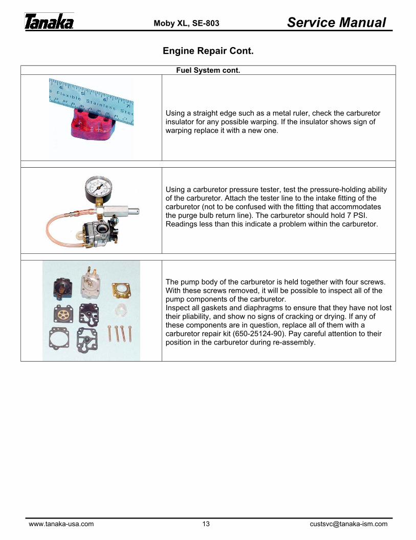
Using a straight edge such as a metal ruler, check the carburetor insulator for any possible warping. If the insulator shows sign of warping replace it with a new one.
Using a carburetor pressure tester, test the pressure-holding ability of the carburetor. Attach the tester line to the intake fitting of the carburetor (not to be confused with the fitting that accommodates the purge bulb return line). The carburetor should hold 7 PSI. Readings less than this indicate a problem within the carburetor.
The pump body of the carburetor is held together with four screws. With these screws removed, it will be possible to inspect all of the pump components of the carburetor. Inspect all gaskets and diaphragms to ensure that they have not lost their pliability, and show no signs of cracking or drying. If any of these components are in question, replace all of them with a carburetor repair kit (650-25124-90). Pay careful attention to their position in the carburetor during re-assembly.

www.tanaka-usa.com 14 [email protected]
Service Manual Moby XL, SE-803
Engine Repair Cont.
CARBURETOR SERVICE
The main body of the carburetor consists of the carburetor body (A), the throttle shaft (B) and the throttle wire receiver (C). Two screws secure the throttle wire receiver and the throttle shaft to the carburetor body. While it’s not necessary to remove the throttle valve for inspection, rotate it by hand to ensure that it is able to freely rotate with the carburetor body and that it can reach the full range of motion permitted between the idle adjustment screw and the full RPM stopper on the carburetor body. Any binding should be addressed by blowing forced air into the throttle valve/body area. If it still does not rotate freely, the entire carburetor will need to be replaced. Also ensure that the o-ring mounted to the carburetor body on the air cleaner side is not torn or dried. Replace as necessary. (The o-ring is a component contained within the carburetor repair kit.)
The fuel tank is mounted to the crankcase with three screws that extend from underneath the tank, and through the tank-mounting bracket. Additionally, there are three small spacers that fit within the bolt holes in the fuel tank itself. Inspect the tank, tank cap, tank vent and fuel lines for any signs of leakage or damage. Replace as needed. With the fuel supply line disconnected from the carburetor it is possible to check the integrity of the fuel filter. With the tank cap securely tightened, and the clear fuel return line still attached or blocked off, gently shake the tank while partially filled with gasoline. If the filter is allowing gas to flow, the agitation of the fuel in the tank will force fuel up and out of the fuel line. If the fuel filter is in question, replace it.
EXHAUST SYSTEM
The exhaust system consists of the muffler / catalytic converter (1), heat shield (2) and muffler gasket (1). The muffler is a sealed, non-serviceable unit that houses the catalyst. If the muffler is damaged or the integrity of the catalyst is in question, the entire unit needs to be replaced.
Remove the shroud covering the muffler and cylinder. Remove the muffler and inspect the exhaust port and mating portion of muffler for any build of carbon. Carbon build up is a normal occurrence in a two-cycle engine, and removal is a matter of routine maintenance.
www.tanaka-usa.com 15 [email protected]
Service Manual Moby XL, SE-803
Engine Repair Cont.
CRANKCASE / ENGINE
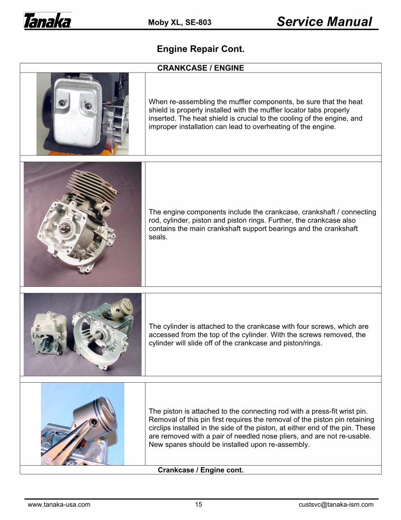
When re-assembling the muffler components, be sure that the heat shield is properly installed with the muffler locator tabs properly inserted. The heat shield is crucial to the cooling of the engine, and improper installation can lead to overheating of the engine.
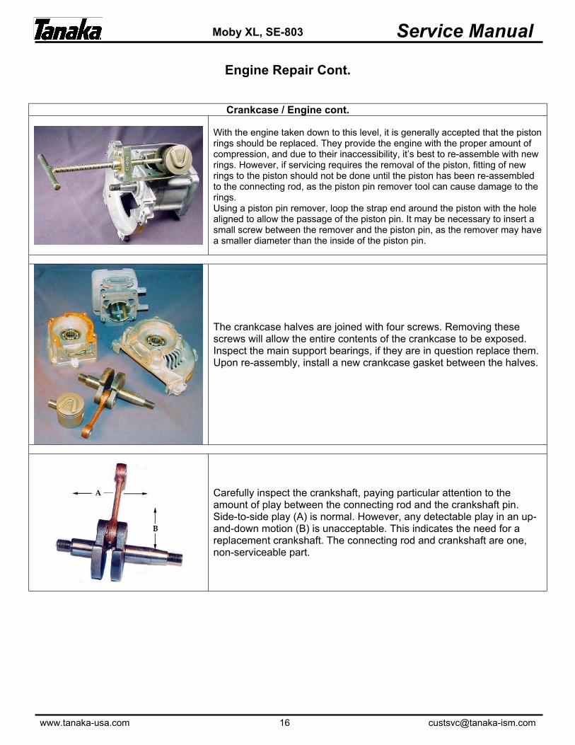
The engine components include the crankcase, crankshaft / connecting rod, cylinder, piston and piston rings. Further, the crankcase also contains the main crankshaft support bearings and the crankshaft seals.
The cylinder is attached to the crankcase with four screws, which are accessed from the top of the cylinder. With the screws removed, the cylinder will slide off of the crankcase and piston/rings.
The piston is attached to the connecting rod with a press-fit wrist pin. Removal of this pin first requires the removal of the piston pin retaining circlips installed in the side of the piston, at either end of the pin. These are removed with a pair of needled nose pliers, and are not re-usable. New spares should be installed upon re-assembly.
Crankcase / Engine cont.
www.tanaka-usa.com 16 [email protected]
Service Manual Moby XL, SE-803
Engine Repair Cont.
Crankcase / Engine cont.
With the engine taken down to this level, it is generally accepted that the piston rings should be replaced. They provide the engine with the proper amount of compression, and due to their inaccessibility, it’s best to re-assemble with new rings. However, if servicing requires the removal of the piston, fitting of new rings to the piston should not be done until the piston has been re-assembled to the connecting rod, as the piston pin remover tool can cause damage to the rings. Using a piston pin remover, loop the strap end around the piston with the hole aligned to allow the passage of the piston pin. It may be necessary to insert a small screw between the remover and the piston pin, as the remover may have a smaller diameter than the inside of the piston pin.
The crankcase halves are joined with four screws. Removing these screws will allow the entire contents of the crankcase to be exposed. Inspect the main support bearings, if they are in question replace them. Upon re-assembly, install a new crankcase gasket between the halves.
Carefully inspect the crankshaft, paying particular attention to the amount of play between the connecting rod and the crankshaft pin. Side-to-side play (A) is normal. However, any detectable play in an up-and-down motion (B) is unacceptable. This indicates the need for a replacement crankshaft. The connecting rod and crankshaft are one, non-serviceable part.
www.tanaka-usa.com 17 [email protected]
Service Manual Moby XL, SE-803
Brake Adjustment
Figure 1
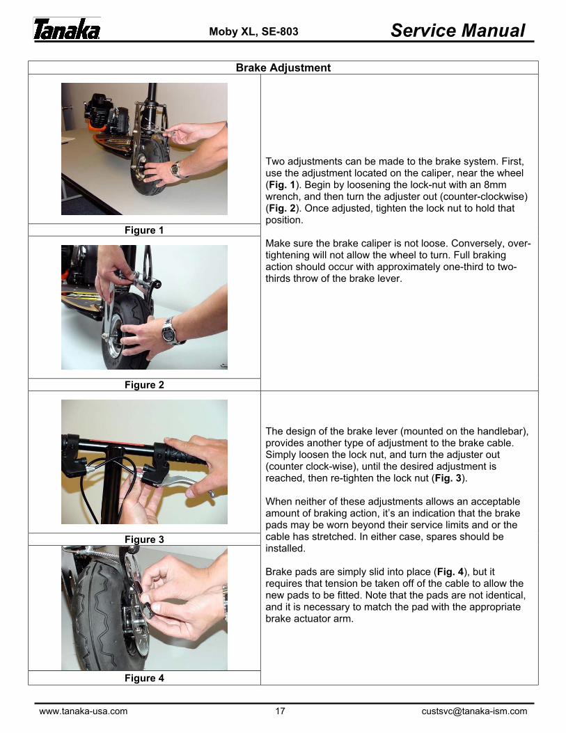
Two adjustments can be made to the brake system. First, use the adjustment located on the caliper, near the wheel (Fig. 1). Begin by loosening the lock-nut with an 8mm wrench, and then turn the adjuster out (counter-clockwise) (Fig. 2). Once adjusted, tighten the lock nut to hold that position. Make sure the brake caliper is not loose. Conversely, over-tightening will not allow the wheel to turn. Full braking action should occur with approximately one-third to two-thirds throw of the brake lever.
Figure 2
Figure 3
The design of the brake lever (mounted on the handlebar), provides another type of adjustment to the brake cable. Simply loosen the lock nut, and turn the adjuster out (counter clock-wise), until the desired adjustment is reached, then re-tighten the lock nut (Fig. 3). When neither of these adjustments allows an acceptable amount of braking action, it’s an indication that the brake pads may be worn beyond their service limits and or the cable has stretched. In either case, spares should be installed. Brake pads are simply slid into place (Fig. 4), but it requires that tension be taken off of the cable to allow the new pads to be fitted. Note that the pads are not identical, and it is necessary to match the pad with the appropriate brake actuator arm.
Figure 4

www.tanaka-usa.com 18 [email protected]
Service Manual Moby XL, SE-803
Wheel Removal - Front Wheel
Figure 5
The front wheel is held in place with a solid axle, and can be removed with two 17mm wrenches and/or sockets. Remove the locking nut from one side of the wheel, and gently tap the axle through the wheel. This will free the wheel assembly from the frame. (Fig. 5) To disassemble the wheel for servicing the tire and/or tube, you must first remove the brake disc. Removal requires a 4mm hex wrench. Note that each of the four bolts use spacers between the disc and the wheel. With the disc removed, it is possible to access the four bolts and nuts that secure the two halves of the wheel assembly together. (Fig. 6) CAUTION: BE SURE TO DEFLATE THE TIRE PRIOR TO ATTEMPTING TO DISASSEMBLE THE TWO WHEEL HALVES. The hardware securing the two wheel halves will require a 13mm wrench or socket and a 6mm hex wrench. With the wheel disassembled, it is advisable to check the integrity of the two ball bearings that ride within the hub of the wheel. If they feel worn or do not turn freely, replace them. Upon re-assembly, ensure that the three axle spacers are properly positioned.
Figure 6

www.tanaka-usa.com 19 [email protected]
Service Manual Moby XL, SE-803
Wheel Removal - Rear Wheel
Rear wheel removal does not require the drive train components be removed. However service to the drive train components will require removal of the wheel.
Figure 7
Begin by removing the axle lock-nut with a 17mm wrench or socket. Gently tap the axle through the wheel. This will allow the rear wheel assembly and the rear drive sprocket to be freed from the frame. (Fig. 7) To disassemble the wheel, begin by removing the outer pulley cover, which is attached with four phillips screws. Next, remove the four bolts (either large phillips head screws, or allen head bolts). CAUTION: BE SURE TO DEFLATE THE TIRE PRIOR TO ATTEMPTING TO DISASSEMBLE THE TWO WHEEL HALVES. The hardware securing the two wheel halves will require a 13mm socket and a 6mm hex wrench. With the wheel disassembled (Fig. 8), it is advisable to check the integrity of the two ball bearings that ride within the hub of the wheel. If they feel worn or do not turn freely, replace them. Upon re-assembly, ensure that the three axle spacers are properly positioned. For belt adjustment procedures, see page 11.
Figure 8

www.tanaka-usa.com 20 [email protected]
Service Manual Moby XL, SE-803
Steering Head Components
Service to the steering head components requires the removal of the front wheel, and the forks that the front wheel mounts to. NOTE: If it is not necessary to disassemble the wheel, the entire front wheel assembly can be removed from the frame with the forks attached.
First, remove the two bolts, four spacers and lock nuts that secure the forks to the steering head. This requires either a 5mm or 6mm hex wrench, and a 13mm wrench or socket. Remove the lock nuts on the bolts, and gently tap them through the steering head assembly (Fig. 9). Use caution not to damage the threads as you remove the bolts. With the entire front wheel and forks removed (Fig. 10), the steering head can now be disassembled.
Figure 9
Figure 10 Figure 11
Slide the upper plastic cover up the handlebar stem, and out of the way. Remove the lower plastic cap. Removal of these caps reveals the large, 40mm nuts that secure the steering head assembly from the top and bottom. It is not necessary to remove the large top nut. The steering head is held in place by two bottom 40mm nuts. One is intended to provide adjustment, and is closest to the steering head, and the one directly beneath it is a jamb nut to ensure they do not come loose in operation. With these bottom nuts removed, remove the lower bearing and spacer. This will enable the entire down-tube, with the upper bearing, to be slid out the top of the steering head. It will be necessary to fold the front steering handle to the down position (Fig. 11) to allow enough slack in the control cables for the steering stem to be lifted from the steering head. Note – within the steering head there is a rubber bushing that acts as a shim between the down-tube and the inside of the steering head. Remove the bushing and thoroughly grease both the inner and outer surfaces of the bushing (Fig. 12). A lack of grease on this bushing will result in difficult turning of the handle bars. Take the opportunity to thoroughly clean all parts with cleaning solvent, and inspect bearings. If they feel worn or do not turn freely, replace them. Re-grease the bearings and carefully re-assemble.
Figure 12
www.tanaka-usa.com 21 [email protected]
Service Manual Moby XL, SE-803
Cables / Controls
On the Moby PowerBoard, the front disc brake and throttle are cable actuated. Cables should be periodically inspected to ensure that they move smoothly, and offer full range of motion in order to maximize braking ability and full range of throttle. Cables that have been kinked, corroded, frayed or worn significantly should be replaced.
Throttle Cable
Figure 13
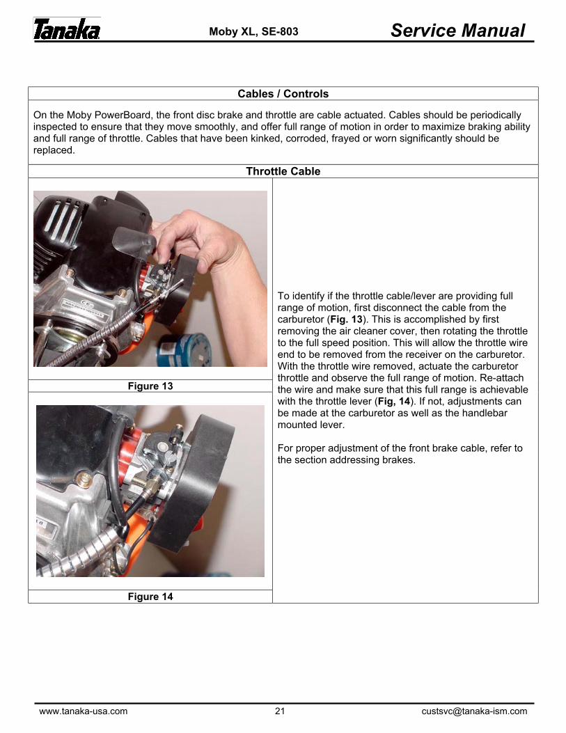
To identify if the throttle cable/lever are providing full range of motion, first disconnect the cable from the carburetor (Fig. 13). This is accomplished by first removing the air cleaner cover, then rotating the throttle to the full speed position. This will allow the throttle wire end to be removed from the receiver on the carburetor. With the throttle wire removed, actuate the carburetor throttle and observe the full range of motion. Re-attach the wire and make sure that this full range is achievable with the throttle lever (Fig, 14). If not, adjustments can be made at the carburetor as well as the handlebar mounted lever. For proper adjustment of the front brake cable, refer to the section addressing brakes.
Figure 14

www.tanaka-usa.com 22 [email protected]
Service Manual Moby XL, SE-803
Belt Adjustment
Figure 15
The Moby PowerBoard uses a dual stage, belt driven system to transmit power to the rear wheel. Belts should be regularly inspected for adjustment. Both belts are adjusted with two procedures. Tighten both belt adjusters on either side of the frame (Fig. 15) in equal increments until the small belt has approximately ½ inch of play when measured between the pulleys. Next, loosen the rear axle lock nut, using a 17mm wrench or socket. Adjust the tension in the larger belt by using the rear wheel adjusters located at the rear of the frame, behind the wheel (Fig. 16). The belt should have approximately ½ inch of play. Make sure that the wheel is lined up in the center of the frame. After adjustment, test ride the unit for a short distance to ensure that the belts ride in the center of their pulleys. If they tend to ride on one side of the pulley(s), adjust the opposite side adjuster until the belt centers on the pulley, being careful to maintain the correct belt tension.
Figure 16
www.tanaka-usa.com 23 [email protected]
Service Manual Moby XL, SE-803
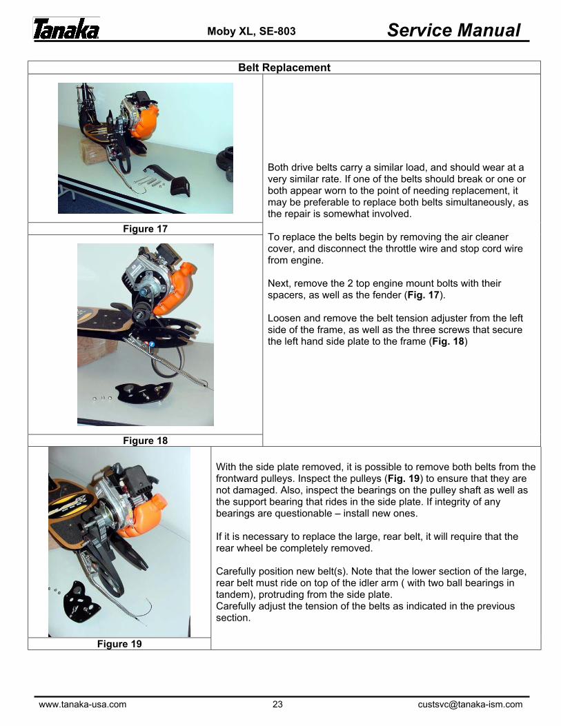
Belt Replacement
Figure 17
Both drive belts carry a similar load, and should wear at a very similar rate. If one of the belts should break or one or both appear worn to the point of needing replacement, it may be preferable to replace both belts simultaneously, as the repair is somewhat involved. To replace the belts begin by removing the air cleaner cover, and disconnect the throttle wire and stop cord wire from engine. Next, remove the 2 top engine mount bolts with their spacers, as well as the fender (Fig. 17). Loosen and remove the belt tension adjuster from the left side of the frame, as well as the three screws that secure the left hand side plate to the frame (Fig. 18)
Figure 18
With the side plate removed, it is possible to remove both belts from the frontward pulleys. Inspect the pulleys (Fig. 19) to ensure that they are not damaged. Also, inspect the bearings on the pulley shaft as well as the support bearing that rides in the side plate. If integrity of any bearings are questionable – install new ones. If it is necessary to replace the large, rear belt, it will require that the rear wheel be completely removed. Carefully position new belt(s). Note that the lower section of the large, rear belt must ride on top of the idler arm ( with two ball bearings in tandem), protruding from the side plate. Carefully adjust the tension of the belts as indicated in the previous section.
Figure 19

www.tanaka-usa.com 24 [email protected]
Service Manual Moby XL, SE-803
Deck Removal
The Moby deck is fastened to the frame with 10 bolts requiring a 4mm hex wrench and a 10mm open-end wrench. Some of these bolts are secured on the bottom side with locking nuts, and some of the bolts are simply threaded into the frame itself. For those bolts secured with nuts on the underside, remove the nuts prior to attempting to remove the bolts from the top. Additionally, six of the mounting bolts are covered by grip tape (four rear / two front), and access to them will require the removal of the grip tape. Inspect the board for any damage and replace as necessary. When re-installing a deck, always ensure that all fasteners are used, and that an adequate amount of grip tape is re-applied to ensure sound footing when in operation.
Figure 20
www.tanaka-usa.com 25 [email protected]
Service Manual Moby XL, SE-803
WARRANTY STATEMENT
Tanaka Kogyo Co., Ltd. ("Tanaka") hereby warrants its utility engines to be free from defects in material or workmanship for a period of 180 DAYS after delivery to the first consumer end user in a non-commercial application. All components on PureFire engines related to the emission control system will carry a 2 YEAR warranty. In the event that the product is used for "commercial", "rental" or "competition" purposes, the warranty shall be VOID. All Tanaka supplied accessories, attachments, and replacement parts will carry a 90 DAYS part replacement warranty. This warranty is limited to repair or replacement, by Tanaka or at the premises of Tanaka Authorized Service Dealers, of such parts as appear to Tanaka, upon inspection, to be defective in material and/or workmanship. The above warranties are extended to the first end user, and no warranty is made, nor authorized to be made assignable, on resale by the first end user. Tanaka makes no warranty with respect to accessories or replacement parts not manufactured by Tanaka or sold by it. Such items are subject to the warranty policy of their respective manufacturers. For the name and address of your nearest Authorized Tanaka Service Dealer, call or write Tanaka c/o International Sales & Marketing Inc. at 1028 4th Street S.W., Bldg. "B", Auburn, WA 98001 (253) 333-1200 or visit their website: www.tanaka-usa.com. To obtain performance of any obligation under this warranty for failure during the applicable warranty period, deliver the Tanaka product, shipping prepaid, to Tanaka c/o International Sales & Marketing Inc., or to the nearest Tanaka Authorized Service Dealer. Tanaka reserves the right to inspect the claimed defective part(s) to determine if the malfunction is the result of a defect covered by this warranty. This warranty will cover only defects arising under normal usage, and shall not apply, nor will Tanaka assume any responsibility, if the failure was caused by the following: 1. Operation of product with incorrect fuel to oil ratio. 2. Misuse or abuse. 3. Negligence. 4. Accident or physical damage. 5. Repairs made by unauthorized parties and/or with unauthorized parts. 6. Improper set up or altering the engine. 7. Improper adjustments (e.g. carburetor, etc.) 8. Operation of engine speeds above Tanaka recommendations. 9. Failures due to contaminated fuel. 10. Failure to operate the unit in the manner specified by the "owner's manual". 11. Use of non-approved accessories or attachments or anything that alters the emission control system. Normal maintenance of the fuel system, spark plug, spark arrester or air filter; adjustments to the carburetor or replacement of wear items such as clutch components are not considered the responsibility of Tanaka under this warranty. THIS LIMITED WARRANTY IS IN LIEU OF ALL OTHER EXPRESS WARRANTIES, OBLIGATIONS, OR LIABILITIES. ANY IMPLIED WARRANTIES, OBLIGATIONS, OR LIABILITIES INCLUDING, BUT NOT LIMITED TO, ANY IMPLIED WARRANTY OF MERCHANTABILITY SHALL BE LIMITED IN DURATION TO THE APPLICABLE WARRANTY PERIOD (AS STATED PREVIOUSLY). ANY ACTION FOR BREACH OF ANY WARRANTY HEREUNDER INCLUDING, BUT NOT LIMITED TO, ANY IMPLIED WARRANTY OF MERCHANTABILITY MUST BE BROUGHT WITHIN A PERIOD OF SIX MONTHS FROM THE END OF THE APPLICABLE WARRANTY PERIOD. Some states do not allow limitations on how long an implied warranty lasts, so the previously stated limitations may not apply to you. No agent, representative, dealer, or employee of Tanaka or International Sales & Marketing Inc. has the authority to increase or alter the obligations of this warranty. IF THE PRODUCT IS USED IN A COMMERCIAL OR COMPETITIVE ENDEAVOR, TANAKA WILL NOT BE LIABLE FOR GENERAL DAMAGES INCLUDING BODILY INJURIES, EXCEPT AS SET FORTH ABOVE, OR FOR INCIDENTAL OR CONSEQUENTIAL DAMAGES INCLUDING, BUT NOT LIMITED TO, LOSS OF USE, LOSS OF PROFITS, LOSS OF PRODUCTION, EXPENSE OF SUBSTITUTE EQUIPMENT OR OTHER COMMERCIAL LOSS OR DAMAGE. THE SAME LIMITATIONS SHALL APPLY TO A PRODUCT USED FOR CONSUMER PURPOSES WITH RESPECT TO ALL NON-PERSONAL INJURY, GENERAL INCIDENTAL AND CONSEQUENTIAL DAMAGES. Some states do not allow the exclusion or limitation of incidental of consequential damages, so the above limitation or exclusion may not apply to you. This warranty gives you specific legal rights, and you may also have other rights which vary from state to state. THE CALIFORNIA AIR RESOURCES BOARD AND TANAKA KOGYO CO., LTD. (TANAKA) ARE PLEASED TO EXPLAIN THE EMISSION CONTROL SYSTEM WARRANTY ON YOUR TANAKA ENGINE. NEW SMALL OFF ROAD ENGINES MUST BE DESIGNED, BUILT AND EQUIPPED TO MEET STRINGENT CALIFORNIA ANTI-SMOG STANDARDS. TANAKA MUST WARRANT THE EMISSION CONTROL SYSTEM ON SMALL OFF ROAD ENGINE FOR THE PERIODS OF TIME LISTED BELOW, PROVIDED THERE HAS BEEN NO ABUSE, NEGLECT OR IMPROPER MAINTENANCE OF YOUR LAWN AND GARDEN EQUIPMENT ENGINE. YOUR EMISSION CONTROL SYSTEM INCLUDES PARTS SUCH AS THE CARBURETOR, THE IGNITION SYSTEM AND THE CATALYTIC CONVERTER (WHICH IS INCORPORATED IN TO THE MUFFLER ON THIS ENGINE). WHERE A WARRANTABLE CONDITION EXISTS, TANAKA WILL REPAIR YOUR ENGINE AT NO COST TO YOU INCLUDING DIAGNOSIS, PARTS AND LABOR. MANUFACTURER'S EMISSION CONTROL WARRANTY COVERAGE: THE EMISSION CONTROL SYSTEM ON 1995 AND LATER SMALL OFF ROAD ENGINES ARE WARRANTED FOR TWO YEARS. IF ANY EMISSION RELATED PART ON YOUR ENGINE IS DEFECTIVE, THE PART WILL BE REPAIRED OR REPLACED BY TANAKA. OWNER'S WARRANTY RESPONSIBILITIES: AS THE SMALL OFF ROAD ENGINE OWNER, YOU ARE RESPONSIBLE FOR THE PERFORMANCE OF THE REQUIRED MAINTENANCE LISTED IN YOUR OWNER'S MANUAL. TANAKA RECOMMENDS THAT YOU RETAIN ALL RECEIPTS COVERING MAINTENANCE ON YOUR SMALL OFF ROAD ENGINE, BUT CANNOT DENY WARRANTY SOLELY FOR THE LACK OF RECEIPTS OR FOR YOUR FAILURE TO ENSURE THE PERFORMANCE OF ALL SCHEDULED MAINTENANCE. AS THE SMALL OFF ROAD ENGINE OWNER, YOU SHOULD BE AWARE, HOWEVER, THAT TANAKA MAY DENY YOU WARRANTY COVERAGE IF YOUR SMALL OFF ROAD ENGINE OR A PART HAS FAILED DUE TO ABUSE, NEGLECT, IMPROPER MAINTENANCE OR UNAPPROVED MODIFICATIONS. YOU ARE RESPONSIBLE FOR PRESENTING YOUR SMALL OFF ROAD ENGINE TO A TANAKA SERVICE CENTER AS SOON AS A PROBLEM EXISTS. THE WARRANTY REPAIRS SHOULD BE COMPLETED IN A REASONABLE AMOUNT OF TIME, NOT TO EXCEED 30 DAYS. IF YOU HAVE ANY QUESTIONS REGARDING YOUR WARRANTY RIGHTS AND RESPONSIBILITIES, YOU SHOULD CONTACT TANAKA C/O INTERNATIONAL SALES & MARKETING, INC., CUSTOMER SERVICE DEPT. AT (253) 333-1200.