Service Manual Horizon II Macro
260
MAINTENANCE INFORMATION AND PARTS INDEX TECHNICAL DESCRIPTION
Transcript of Service Manual Horizon II Macro

MAINTENANCEINFORMATION AND PARTS
INDEXTECHNICAL DESCRIPTION

SERVICE MANUALHorizon II macro
GMR-01
68P02902W96-A

SERVICE MANUALHorizon II macro
GM
R-0
1
68P
0290
2W96
-A

26 Sep 2003
Service Manual: Horizon II macro68P02902W96-A
GMR-01GMR Page 1
Manual RevisionGMR-01
26 Sep 200368P02902W96-A
Motorola manualaffected
Incorporate this GMR only in the manual number and version listed below:
68P02902W96-A SERVICE MANUAL: Horizon II macro
Problem reports
This revision provides a fix to the following problem reports:
No new Service Requests fixed in this revision.
Reason forrevision
This revision provides additional and updated information as follows:
Tech. Chap. 1: Page Tech. 1-13: Table Tech. 1-4 revised � current supply figurescorrected. Table Tech. 1-5 revised � cabinet power consumptionfigures updated and PSU output figures added. Battery backupsection moved here from page Tech 1-15.
Page Tech. 1-14: Thermal dissipation section deleted. Minor changeto Table Tech. 1-7. Note added to clarify measurement point for RFoutput power.
Page Tech. 1-15: Sensitivity section rewritten.
Tech. Chap. 4: Page Tech. 4-9: Text clarified to refer to Horizonmacro indoor only.
Page Tech. 4-19: Text clarified to refer to Horizonmacro indoor only.
Tech. Chap. 5: Page Tech. 5-5: Note added
Maint. Chap. 2: Page Maint. 2-17: M4 Torx driver changed to T20 Torx driver in step 3and step 7.
Page Maint. 2-21: M4 Torx driver changed to T20 Torx driver in step 6.
Page Maint. 2-22: M4 Torx driver changed to T20 Torx driver in step 4.
Page Maint. 2-38: cal_test_mode on command added to Rxbay level calibration procedure.
Page Maint. 2-55: Note added.
Maint. Chap. 3: Page Maint. 3-16: cal_test_mode on command added to Txoutput power calibration procedure.
Page Maint. 3-17: Steps 9 and 11 of Tx output power calibrationprocedure rewritten.
Page Maint. 3-18: RF channel and frequency numbers changed.
GSM
26 Sep 2003GMR Page 2Service Manual: Horizon II macro
GMR-0168P02902W96-A
Action
Remove and replace pages in the Manual as follows:
Remove Insert
All pages between the clear acetatefront sheet and the blank backingsheet, remove from binder.
All pages of the GMR between thefront sheet and the blank backingsheet, insert into binder.
Obsolete pages
Destroy all obsolete pages. Do not destroy this page.
Completion
On completion of the Manual Revision, insert this Manual Revision sheet in thefront or back of the manual, for future reference.
26 Sep 2003
Service Manual: Horizon II macro68P02902W96-A
GMR-01i
GSM
Service ManualHorizon II macro
E Motorola 2002 - 2003All Rights ReservedPrinted in the UK.
GSM
26 Sep 2003iiService Manual: Horizon II macro
GMR-0168P02902W96-A
Copyrights, notices and trademarks
CopyrightsThe Motorola products described in this document may include copyrighted Motorola computerprograms stored in semiconductor memories or other media. Laws in the United States and othercountries preserve for Motorola certain exclusive rights for copyright computer programs, including theexclusive right to copy or reproduce in any form the copyright computer program. Accordingly, anycopyright Motorola computer programs contained in the Motorola products described in this documentmay not be copied or reproduced in any manner without the express written permission of Motorola.Furthermore, the purchase of Motorola products shall not be deemed to grant either directly or byimplication, estoppel or otherwise, any license under the copyrights, patents or patent applications ofMotorola, except for the rights that arise by operation of law in the sale of a product.
RestrictionsThe software described in this document is the property of Motorola. It is furnished under a licenseagreement and may be used and/or disclosed only in accordance with the terms of the agreement.Software and documentation are copyright materials. Making unauthorized copies is prohibited bylaw. No part of the software or documentation may be reproduced, transmitted, transcribed, storedin a retrieval system, or translated into any language or computer language, in any form or by anymeans, without prior written permission of Motorola.
AccuracyWhile reasonable efforts have been made to assure the accuracy of this document, Motorolaassumes no liability resulting from any inaccuracies or omissions in this document, or from the useof the information obtained herein. Motorola reserves the right to make changes to any productsdescribed herein to improve reliability, function, or design, and reserves the right to revise thisdocument and to make changes from time to time in content hereof with no obligation to notify anyperson of revisions or changes. Motorola does not assume any liability arising out of the applicationor use of any product or circuit described herein; neither does it convey license under its patentrights of others.
Trademarks
and MOTOROLA are registered trademarks of Motorola Inc. Intelligence Everywhere, M-Cell and Taskfinder are trademarks of Motorola Inc.All other brands and corporate names are trademarks of their respective owners.
.
.
.
GSM
26 Sep 2003
Service Manual: Horizon II macro68P02902W96-A
GMR-01iii
Contents
Issue status of this manual 1 . . . . . . . . . . . . . . . . . . . . . . . . . . . . . . . . . . . . . . . . . . . .
General information 2 . . . . . . . . . . . . . . . . . . . . . . . . . . . . . . . . . . . . . . . . . . . . . . . . . .
Reporting safety issues 5 . . . . . . . . . . . . . . . . . . . . . . . . . . . . . . . . . . . . . . . . . . . . . . .
Warnings and cautions 6 . . . . . . . . . . . . . . . . . . . . . . . . . . . . . . . . . . . . . . . . . . . . . . .
General warnings 7 . . . . . . . . . . . . . . . . . . . . . . . . . . . . . . . . . . . . . . . . . . . . . . . . . . . .
General cautions 11 . . . . . . . . . . . . . . . . . . . . . . . . . . . . . . . . . . . . . . . . . . . . . . . . . . . . .
Devices sensitive to static 12 . . . . . . . . . . . . . . . . . . . . . . . . . . . . . . . . . . . . . . . . . . . . .
Motorola manual set 13 . . . . . . . . . . . . . . . . . . . . . . . . . . . . . . . . . . . . . . . . . . . . . . . . . .
GMR amendment 17 . . . . . . . . . . . . . . . . . . . . . . . . . . . . . . . . . . . . . . . . . . . . . . . . . . . .
GMR amendment record 18 . . . . . . . . . . . . . . . . . . . . . . . . . . . . . . . . . . . . . . . . . . . . . .
Technical Description (Tech.) i . . . . . . . . . . . . . . . . . . . . . . . . . . . . . . . . . . . . . . .
Chapter 1Introduction to the Horizon II macro Tech. 1�1 . . . . . . . . . . . . . . . . . . . . . . . . . . . .
Equipment introduction Tech. 1�3 . . . . . . . . . . . . . . . . . . . . . . . . . . . . . . . . . . . . . . . . . . . . . . . Overview of the Horizon II macro Tech. 1�3 . . . . . . . . . . . . . . . . . . . . . . . . . . . . . . . . . Finding information in this manual Tech. 1�4 . . . . . . . . . . . . . . . . . . . . . . . . . . . . . . . . . Names and acronyms for main cabinet equipment Tech. 1�5 . . . . . . . . . . . . . . . . . . Cabinet inside view Tech. 1�7 . . . . . . . . . . . . . . . . . . . . . . . . . . . . . . . . . . . . . . . . . . . . . Horizon II macro stacking capability Tech. 1�8 . . . . . . . . . . . . . . . . . . . . . . . . . . . . . . . Functional diagram of Horizon II macro Tech. 1�9 . . . . . . . . . . . . . . . . . . . . . . . . . . . .
Horizon II macro comparison with Horizonmacro Tech. 1�10 . . . . . . . . . . . . . . . . . . . . . . . . . Comparison overview Tech. 1�10 . . . . . . . . . . . . . . . . . . . . . . . . . . . . . . . . . . . . . . . . . . . Compatibility with Horizonmacro and M-Cell6 Tech. 1�10 . . . . . . . . . . . . . . . . . . . . . . . Comparison of Horizon II macro with Horizonmacro Tech. 1�11 . . . . . . . . . . . . . . . . .
Specifications Tech. 1�12 . . . . . . . . . . . . . . . . . . . . . . . . . . . . . . . . . . . . . . . . . . . . . . . . . . . . . . . Overview of specifications Tech. 1�12 . . . . . . . . . . . . . . . . . . . . . . . . . . . . . . . . . . . . . . . Software requirements Tech. 1�12 . . . . . . . . . . . . . . . . . . . . . . . . . . . . . . . . . . . . . . . . . . Approval and safety Tech. 1�12 . . . . . . . . . . . . . . . . . . . . . . . . . . . . . . . . . . . . . . . . . . . . . Environmental limits Tech. 1�12 . . . . . . . . . . . . . . . . . . . . . . . . . . . . . . . . . . . . . . . . . . . . . Power requirements Tech. 1�13 . . . . . . . . . . . . . . . . . . . . . . . . . . . . . . . . . . . . . . . . . . . . . Battery backup Tech. 1�13 . . . . . . . . . . . . . . . . . . . . . . . . . . . . . . . . . . . . . . . . . . . . . . . . . RF power output Tech. 1�14 . . . . . . . . . . . . . . . . . . . . . . . . . . . . . . . . . . . . . . . . . . . . . . . . Sensitivity Tech. 1�15 . . . . . . . . . . . . . . . . . . . . . . . . . . . . . . . . . . . . . . . . . . . . . . . . . . . . . . BSC connectivity options Tech. 1�15 . . . . . . . . . . . . . . . . . . . . . . . . . . . . . . . . . . . . . . . . Cabinet dimensions Tech. 1�16 . . . . . . . . . . . . . . . . . . . . . . . . . . . . . . . . . . . . . . . . . . . . . Weights Tech. 1�16 . . . . . . . . . . . . . . . . . . . . . . . . . . . . . . . . . . . . . . . . . . . . . . . . . . . . . . . . Torque values Tech. 1�16 . . . . . . . . . . . . . . . . . . . . . . . . . . . . . . . . . . . . . . . . . . . . . . . . . . Frequency capability Tech. 1�17 . . . . . . . . . . . . . . . . . . . . . . . . . . . . . . . . . . . . . . . . . . . . Structural considerations Tech. 1�18 . . . . . . . . . . . . . . . . . . . . . . . . . . . . . . . . . . . . . . . . . Layout plan Tech. 1�18 . . . . . . . . . . . . . . . . . . . . . . . . . . . . . . . . . . . . . . . . . . . . . . . . . . . .
GSM
26 Sep 2003ivService Manual: Horizon II macro
GMR-0168P02902W96-A
Chapter 2Cabinet structure Tech. 2�1 . . . . . . . . . . . . . . . . . . . . . . . . . . . . . . . . . . . . . . . . . . . . . . Horizon II macro cabinet structure Tech. 2�3 . . . . . . . . . . . . . . . . . . . . . . . . . . . . . . . . . . . . . .
External cabinet views Tech. 2�3 . . . . . . . . . . . . . . . . . . . . . . . . . . . . . . . . . . . . . . . . . . . Overview of structure description Tech. 2�4 . . . . . . . . . . . . . . . . . . . . . . . . . . . . . . . . . Filled cabinet view Tech. 2�5 . . . . . . . . . . . . . . . . . . . . . . . . . . . . . . . . . . . . . . . . . . . . . .
Empty cabinet and SURF2 harness Tech. 2�6 . . . . . . . . . . . . . . . . . . . . . . . . . . . . . . . . . . . . SURF2 harness and components Tech. 2�6 . . . . . . . . . . . . . . . . . . . . . . . . . . . . . . . . . Cabinet view with installed SURF2 harness components Tech. 2�7 . . . . . . . . . . . . .
Top panel Tech. 2�8 . . . . . . . . . . . . . . . . . . . . . . . . . . . . . . . . . . . . . . . . . . . . . . . . . . . . . . . . . . . Top panel description Tech. 2�8 . . . . . . . . . . . . . . . . . . . . . . . . . . . . . . . . . . . . . . . . . . . . Top panel view Tech. 2�8 . . . . . . . . . . . . . . . . . . . . . . . . . . . . . . . . . . . . . . . . . . . . . . . . .
Cage backplane interface panel harness assembly (CBIA) Tech. 2�9 . . . . . . . . . . . . . . . . CBIA overview Tech. 2�9 . . . . . . . . . . . . . . . . . . . . . . . . . . . . . . . . . . . . . . . . . . . . . . . . . . CBIA diagram Tech. 2�9 . . . . . . . . . . . . . . . . . . . . . . . . . . . . . . . . . . . . . . . . . . . . . . . . . . Backplane and harness view Tech. 2�10 . . . . . . . . . . . . . . . . . . . . . . . . . . . . . . . . . . . . . CBIA cage function and diagram Tech. 2�11 . . . . . . . . . . . . . . . . . . . . . . . . . . . . . . . . . . CBIA harness function Tech. 2�11 . . . . . . . . . . . . . . . . . . . . . . . . . . . . . . . . . . . . . . . . . . . CBIA backplane function and diagram Tech. 2�12 . . . . . . . . . . . . . . . . . . . . . . . . . . . . . Attachment of cage to cabinet Tech. 2�12 . . . . . . . . . . . . . . . . . . . . . . . . . . . . . . . . . . . . Interface panel function Tech. 2�13 . . . . . . . . . . . . . . . . . . . . . . . . . . . . . . . . . . . . . . . . . . Interface panel diagram Tech. 2�13 . . . . . . . . . . . . . . . . . . . . . . . . . . . . . . . . . . . . . . . . . . Interface panel pinouts Tech. 2�13 . . . . . . . . . . . . . . . . . . . . . . . . . . . . . . . . . . . . . . . . . .
Cabinet temperature control Tech. 2�14 . . . . . . . . . . . . . . . . . . . . . . . . . . . . . . . . . . . . . . . . . . . Temperature control overview Tech. 2�14 . . . . . . . . . . . . . . . . . . . . . . . . . . . . . . . . . . . . Cabinet overtemperature control Tech. 2�14 . . . . . . . . . . . . . . . . . . . . . . . . . . . . . . . . . . Temperature sensors Tech. 2�14 . . . . . . . . . . . . . . . . . . . . . . . . . . . . . . . . . . . . . . . . . . . . Cabinet restart after shutdown Tech. 2�14 . . . . . . . . . . . . . . . . . . . . . . . . . . . . . . . . . . . .
Fan unit description Tech. 2�15 . . . . . . . . . . . . . . . . . . . . . . . . . . . . . . . . . . . . . . . . . . . . . . . . . . Fan unit overview Tech. 2�15 . . . . . . . . . . . . . . . . . . . . . . . . . . . . . . . . . . . . . . . . . . . . . . . Fan operation Tech. 2�15 . . . . . . . . . . . . . . . . . . . . . . . . . . . . . . . . . . . . . . . . . . . . . . . . . .
Cabinet door and optional hood Tech. 2�16 . . . . . . . . . . . . . . . . . . . . . . . . . . . . . . . . . . . . . . . . Door function Tech. 2�16 . . . . . . . . . . . . . . . . . . . . . . . . . . . . . . . . . . . . . . . . . . . . . . . . . . . Door external and internal view Tech. 2�16 . . . . . . . . . . . . . . . . . . . . . . . . . . . . . . . . . . . Hood function Tech. 2�17 . . . . . . . . . . . . . . . . . . . . . . . . . . . . . . . . . . . . . . . . . . . . . . . . . . View of hood Tech. 2�17 . . . . . . . . . . . . . . . . . . . . . . . . . . . . . . . . . . . . . . . . . . . . . . . . . . . Securing pins and hood removal Tech. 2�17 . . . . . . . . . . . . . . . . . . . . . . . . . . . . . . . . . .
Stacking bracket Tech. 2�18 . . . . . . . . . . . . . . . . . . . . . . . . . . . . . . . . . . . . . . . . . . . . . . . . . . . . . Stacking bracket function Tech. 2�18 . . . . . . . . . . . . . . . . . . . . . . . . . . . . . . . . . . . . . . . . Stacking bracket diagram Tech. 2�18 . . . . . . . . . . . . . . . . . . . . . . . . . . . . . . . . . . . . . . . . Stacking bracket front cover function Tech. 2�18 . . . . . . . . . . . . . . . . . . . . . . . . . . . . . . View of stacked cabinets Tech. 2�19 . . . . . . . . . . . . . . . . . . . . . . . . . . . . . . . . . . . . . . . . .
Chapter 3Power distribution Tech. 3�1 . . . . . . . . . . . . . . . . . . . . . . . . . . . . . . . . . . . . . . . . . . . . . Horizon II macro power supplies Tech. 3�3 . . . . . . . . . . . . . . . . . . . . . . . . . . . . . . . . . . . . . . .
Power supply overview Tech. 3�3 . . . . . . . . . . . . . . . . . . . . . . . . . . . . . . . . . . . . . . . . . . Location of power modules Tech. 3�3 . . . . . . . . . . . . . . . . . . . . . . . . . . . . . . . . . . . . . . .
GSM
26 Sep 2003
Service Manual: Horizon II macro68P02902W96-A
GMR-01v
Power supply unit (PSU) Tech. 3�4 . . . . . . . . . . . . . . . . . . . . . . . . . . . . . . . . . . . . . . . . . . . . . . Types and overview of PSU Tech. 3�4 . . . . . . . . . . . . . . . . . . . . . . . . . . . . . . . . . . . . . . PSU location and redundancy Tech. 3�4 . . . . . . . . . . . . . . . . . . . . . . . . . . . . . . . . . . . . PSU module view Tech. 3�5 . . . . . . . . . . . . . . . . . . . . . . . . . . . . . . . . . . . . . . . . . . . . . . . PSU alarms Tech. 3�5 . . . . . . . . . . . . . . . . . . . . . . . . . . . . . . . . . . . . . . . . . . . . . . . . . . . . PSU LEDs Tech. 3�6 . . . . . . . . . . . . . . . . . . . . . . . . . . . . . . . . . . . . . . . . . . . . . . . . . . . . . PSU backplane protection Tech. 3�6 . . . . . . . . . . . . . . . . . . . . . . . . . . . . . . . . . . . . . . .
Circuit breaker card (CBC) Tech. 3�7 . . . . . . . . . . . . . . . . . . . . . . . . . . . . . . . . . . . . . . . . . . . . CBC overview Tech. 3�7 . . . . . . . . . . . . . . . . . . . . . . . . . . . . . . . . . . . . . . . . . . . . . . . . . . View of the CBC Tech. 3�7 . . . . . . . . . . . . . . . . . . . . . . . . . . . . . . . . . . . . . . . . . . . . . . . . Operation of the CBC Tech. 3�8 . . . . . . . . . . . . . . . . . . . . . . . . . . . . . . . . . . . . . . . . . . .
Chapter 4RF modules Tech. 4�1 . . . . . . . . . . . . . . . . . . . . . . . . . . . . . . . . . . . . . . . . . . . . . . . . . . . RF equipment description Tech. 4�3 . . . . . . . . . . . . . . . . . . . . . . . . . . . . . . . . . . . . . . . . . . . . .
Overview of RF equipment Tech. 4�3 . . . . . . . . . . . . . . . . . . . . . . . . . . . . . . . . . . . . . . . RF specifications Tech. 4�3 . . . . . . . . . . . . . . . . . . . . . . . . . . . . . . . . . . . . . . . . . . . . . . . Receive (Rx) RF hardware Tech. 4�4 . . . . . . . . . . . . . . . . . . . . . . . . . . . . . . . . . . . . . . . Transmit (Tx) RF hardware Tech. 4�4 . . . . . . . . . . . . . . . . . . . . . . . . . . . . . . . . . . . . . . . Rx/Tx single antenna duplexing Tech. 4�5 . . . . . . . . . . . . . . . . . . . . . . . . . . . . . . . . . . .
RF overview and antenna VSWR monitoring function Tech. 4�6 . . . . . . . . . . . . . . . . . . . . . RF overview Tech. 4�6 . . . . . . . . . . . . . . . . . . . . . . . . . . . . . . . . . . . . . . . . . . . . . . . . . . . . RF main components Tech. 4�6 . . . . . . . . . . . . . . . . . . . . . . . . . . . . . . . . . . . . . . . . . . . . Antenna VSWR monitoring Tech. 4�7 . . . . . . . . . . . . . . . . . . . . . . . . . . . . . . . . . . . . . . . RF loopback Tech. 4�7 . . . . . . . . . . . . . . . . . . . . . . . . . . . . . . . . . . . . . . . . . . . . . . . . . . . RF functional diagram Tech. 4�8 . . . . . . . . . . . . . . . . . . . . . . . . . . . . . . . . . . . . . . . . . . .
Compact transceiver unit (CTU2) Tech. 4�9 . . . . . . . . . . . . . . . . . . . . . . . . . . . . . . . . . . . . . . . Overview of the CTU2 Tech. 4�9 . . . . . . . . . . . . . . . . . . . . . . . . . . . . . . . . . . . . . . . . . . . CTU2 internal boards Tech. 4�10 . . . . . . . . . . . . . . . . . . . . . . . . . . . . . . . . . . . . . . . . . . . . Alarm reporting Tech. 4�10 . . . . . . . . . . . . . . . . . . . . . . . . . . . . . . . . . . . . . . . . . . . . . . . . . View of a CTU2 Tech. 4�11 . . . . . . . . . . . . . . . . . . . . . . . . . . . . . . . . . . . . . . . . . . . . . . . . . CTU2 front panel detail Tech. 4�12 . . . . . . . . . . . . . . . . . . . . . . . . . . . . . . . . . . . . . . . . . . CTU2 Tx connector Tech. 4�13 . . . . . . . . . . . . . . . . . . . . . . . . . . . . . . . . . . . . . . . . . . . . . CTU2 Rx function Tech. 4�13 . . . . . . . . . . . . . . . . . . . . . . . . . . . . . . . . . . . . . . . . . . . . . . . CTU2 interface function Tech. 4�13 . . . . . . . . . . . . . . . . . . . . . . . . . . . . . . . . . . . . . . . . . .
CTU2 frequency hopping Tech. 4�14 . . . . . . . . . . . . . . . . . . . . . . . . . . . . . . . . . . . . . . . . . . . . . Overview of CTU2 frequency hopping Tech. 4�14 . . . . . . . . . . . . . . . . . . . . . . . . . . . . . Synthesizer frequency hopping (SFH) Tech. 4�14 . . . . . . . . . . . . . . . . . . . . . . . . . . . . . Baseband frequency hopping (BBH) Tech. 4�14 . . . . . . . . . . . . . . . . . . . . . . . . . . . . . .
SURF2 module Tech. 4�15 . . . . . . . . . . . . . . . . . . . . . . . . . . . . . . . . . . . . . . . . . . . . . . . . . . . . . . SURF2 module overview Tech. 4�15 . . . . . . . . . . . . . . . . . . . . . . . . . . . . . . . . . . . . . . . . . SURF2 module view Tech. 4�16 . . . . . . . . . . . . . . . . . . . . . . . . . . . . . . . . . . . . . . . . . . . . SURF2 functional description Tech. 4�17 . . . . . . . . . . . . . . . . . . . . . . . . . . . . . . . . . . . . . SURF2 functional diagram Tech. 4�17 . . . . . . . . . . . . . . . . . . . . . . . . . . . . . . . . . . . . . . . SURF2 to CTU2 interface Tech. 4�18 . . . . . . . . . . . . . . . . . . . . . . . . . . . . . . . . . . . . . . . . SURF to CTU2 interface (Horizonmacro indoor compatibility) Tech. 4�19 . . . . . . . . .
Tx blocks overview Tech. 4�20 . . . . . . . . . . . . . . . . . . . . . . . . . . . . . . . . . . . . . . . . . . . . . . . . . . . Introduction to transmit blocks Tech. 4�20 . . . . . . . . . . . . . . . . . . . . . . . . . . . . . . . . . . . . Screw retention in Tx block locations Tech. 4�20 . . . . . . . . . . . . . . . . . . . . . . . . . . . . . . Tx block connectors Tech. 4�21 . . . . . . . . . . . . . . . . . . . . . . . . . . . . . . . . . . . . . . . . . . . . .
GSM
26 Sep 2003viService Manual: Horizon II macro
GMR-0168P02902W96-A
Blanking plate Tech. 4�22 . . . . . . . . . . . . . . . . . . . . . . . . . . . . . . . . . . . . . . . . . . . . . . . . . . . . . . . Blanking plate function Tech. 4�22 . . . . . . . . . . . . . . . . . . . . . . . . . . . . . . . . . . . . . . . . . . Blanking plate view Tech. 4�22 . . . . . . . . . . . . . . . . . . . . . . . . . . . . . . . . . . . . . . . . . . . . .
Feedthrough plate Tech. 4�23 . . . . . . . . . . . . . . . . . . . . . . . . . . . . . . . . . . . . . . . . . . . . . . . . . . . Feedthrough plate function Tech. 4�23 . . . . . . . . . . . . . . . . . . . . . . . . . . . . . . . . . . . . . . . Feedthrough plate view Tech. 4�23 . . . . . . . . . . . . . . . . . . . . . . . . . . . . . . . . . . . . . . . . . . Feedthrough plate connectors Tech. 4�23 . . . . . . . . . . . . . . . . . . . . . . . . . . . . . . . . . . . .
Duplexer (DUP) Tech. 4�24 . . . . . . . . . . . . . . . . . . . . . . . . . . . . . . . . . . . . . . . . . . . . . . . . . . . . . . DUP function Tech. 4�24 . . . . . . . . . . . . . . . . . . . . . . . . . . . . . . . . . . . . . . . . . . . . . . . . . . . DUP view Tech. 4�24 . . . . . . . . . . . . . . . . . . . . . . . . . . . . . . . . . . . . . . . . . . . . . . . . . . . . . . DUP functional diagram Tech. 4�25 . . . . . . . . . . . . . . . . . . . . . . . . . . . . . . . . . . . . . . . . . DUP connectors Tech. 4�25 . . . . . . . . . . . . . . . . . . . . . . . . . . . . . . . . . . . . . . . . . . . . . . . .
Hybrid combiner unit (HCU) Tech. 4�26 . . . . . . . . . . . . . . . . . . . . . . . . . . . . . . . . . . . . . . . . . . . HCU function Tech. 4�26 . . . . . . . . . . . . . . . . . . . . . . . . . . . . . . . . . . . . . . . . . . . . . . . . . . . HCU view Tech. 4�26 . . . . . . . . . . . . . . . . . . . . . . . . . . . . . . . . . . . . . . . . . . . . . . . . . . . . . . HCU functional diagram Tech. 4�27 . . . . . . . . . . . . . . . . . . . . . . . . . . . . . . . . . . . . . . . . . HCU connectors Tech. 4�27 . . . . . . . . . . . . . . . . . . . . . . . . . . . . . . . . . . . . . . . . . . . . . . . .
Dual hybrid combiner unit (DHU) Tech. 4�28 . . . . . . . . . . . . . . . . . . . . . . . . . . . . . . . . . . . . . . . DHU function Tech. 4�28 . . . . . . . . . . . . . . . . . . . . . . . . . . . . . . . . . . . . . . . . . . . . . . . . . . . DHU view Tech. 4�28 . . . . . . . . . . . . . . . . . . . . . . . . . . . . . . . . . . . . . . . . . . . . . . . . . . . . . . DHU functional diagram Tech. 4�29 . . . . . . . . . . . . . . . . . . . . . . . . . . . . . . . . . . . . . . . . . DHU connectors Tech. 4�29 . . . . . . . . . . . . . . . . . . . . . . . . . . . . . . . . . . . . . . . . . . . . . . . .
Chapter 5Digital modules Tech. 5�1 . . . . . . . . . . . . . . . . . . . . . . . . . . . . . . . . . . . . . . . . . . . . . . . Overview of digital modules Tech. 5�3 . . . . . . . . . . . . . . . . . . . . . . . . . . . . . . . . . . . . . . . . . . .
Introduction to digital modules Tech. 5�3 . . . . . . . . . . . . . . . . . . . . . . . . . . . . . . . . . . . . Digital module locations Tech. 5�4 . . . . . . . . . . . . . . . . . . . . . . . . . . . . . . . . . . . . . . . . . Redundancy Tech. 5�5 . . . . . . . . . . . . . . . . . . . . . . . . . . . . . . . . . . . . . . . . . . . . . . . . . . . Communication between the HIISC and transceivers Tech. 5�6 . . . . . . . . . . . . . . . .
Horizon II macro site controller (HIISC) Tech. 5�7 . . . . . . . . . . . . . . . . . . . . . . . . . . . . . . . . . HIISC overview Tech. 5�7 . . . . . . . . . . . . . . . . . . . . . . . . . . . . . . . . . . . . . . . . . . . . . . . . . HIISC module view Tech. 5�8 . . . . . . . . . . . . . . . . . . . . . . . . . . . . . . . . . . . . . . . . . . . . . . Link to redundant HIISC Tech. 5�8 . . . . . . . . . . . . . . . . . . . . . . . . . . . . . . . . . . . . . . . . . Front panel interfaces Tech. 5�9 . . . . . . . . . . . . . . . . . . . . . . . . . . . . . . . . . . . . . . . . . . . Front panel switches and indicators Tech. 5�10 . . . . . . . . . . . . . . . . . . . . . . . . . . . . . . . PIX interfaces Tech. 5�10 . . . . . . . . . . . . . . . . . . . . . . . . . . . . . . . . . . . . . . . . . . . . . . . . . . SDRAM, flash EPROM and code loading functions Tech. 5�11 . . . . . . . . . . . . . . . . . . HIISC internal architecture Tech. 5�12 . . . . . . . . . . . . . . . . . . . . . . . . . . . . . . . . . . . . . . . RSL configuration and control Tech. 5�15 . . . . . . . . . . . . . . . . . . . . . . . . . . . . . . . . . . . . Integral HIISC XMUX functionality Tech. 5�16 . . . . . . . . . . . . . . . . . . . . . . . . . . . . . . . . .
XMUX module Tech. 5�17 . . . . . . . . . . . . . . . . . . . . . . . . . . . . . . . . . . . . . . . . . . . . . . . . . . . . . . . Overview of the XMUX module Tech. 5�17 . . . . . . . . . . . . . . . . . . . . . . . . . . . . . . . . . . . XMUX module view Tech. 5�17 . . . . . . . . . . . . . . . . . . . . . . . . . . . . . . . . . . . . . . . . . . . . . XMUX functional description Tech. 5�18 . . . . . . . . . . . . . . . . . . . . . . . . . . . . . . . . . . . . .
Site expansion board Tech. 5�19 . . . . . . . . . . . . . . . . . . . . . . . . . . . . . . . . . . . . . . . . . . . . . . . . . Expansion board description Tech. 5�19 . . . . . . . . . . . . . . . . . . . . . . . . . . . . . . . . . . . . .
GSM
26 Sep 2003
Service Manual: Horizon II macro68P02902W96-A
GMR-01vii
Alarm module Tech. 5�20 . . . . . . . . . . . . . . . . . . . . . . . . . . . . . . . . . . . . . . . . . . . . . . . . . . . . . . . Alarm module overview Tech. 5�20 . . . . . . . . . . . . . . . . . . . . . . . . . . . . . . . . . . . . . . . . . . Alarm module view Tech. 5�20 . . . . . . . . . . . . . . . . . . . . . . . . . . . . . . . . . . . . . . . . . . . . . . Alarm module functionality Tech. 5�21 . . . . . . . . . . . . . . . . . . . . . . . . . . . . . . . . . . . . . . . Alarm module replacement � effect on alarms Tech. 5�21 . . . . . . . . . . . . . . . . . . . . . . Alarm collection from expansion cabinets Tech. 5�21 . . . . . . . . . . . . . . . . . . . . . . . . . . Alarm module display presentation Tech. 5�21 . . . . . . . . . . . . . . . . . . . . . . . . . . . . . . . .
Maintenance and Parts (Maint.) i . . . . . . . . . . . . . . . . . . . . . . . . . . . . . . . . . . . . .
Chapter 1Routine maintenance Maint. 1�1 . . . . . . . . . . . . . . . . . . . . . . . . . . . . . . . . . . . . . . . . . . Routine maintenance overview Maint. 1�3 . . . . . . . . . . . . . . . . . . . . . . . . . . . . . . . . . . . . . . . .
In this chapter Maint. 1�3 . . . . . . . . . . . . . . . . . . . . . . . . . . . . . . . . . . . . . . . . . . . . . . . . . . Safety Maint. 1�3 . . . . . . . . . . . . . . . . . . . . . . . . . . . . . . . . . . . . . . . . . . . . . . . . . . . . . . . . . Reporting faulty devices Maint. 1�3 . . . . . . . . . . . . . . . . . . . . . . . . . . . . . . . . . . . . . . . . . Routine maintenance intervals Maint. 1�4 . . . . . . . . . . . . . . . . . . . . . . . . . . . . . . . . . . . . Cleaning agents Maint. 1�4 . . . . . . . . . . . . . . . . . . . . . . . . . . . . . . . . . . . . . . . . . . . . . . . . Tools Maint. 1�4 . . . . . . . . . . . . . . . . . . . . . . . . . . . . . . . . . . . . . . . . . . . . . . . . . . . . . . . . . . Assumptions � door, hood, and stacking bracket Maint. 1�4 . . . . . . . . . . . . . . . . . . . . Door operation Maint. 1�5 . . . . . . . . . . . . . . . . . . . . . . . . . . . . . . . . . . . . . . . . . . . . . . . . . Hood removal and refitting Maint. 1�5 . . . . . . . . . . . . . . . . . . . . . . . . . . . . . . . . . . . . . . . Stacking bracket removal Maint. 1�5 . . . . . . . . . . . . . . . . . . . . . . . . . . . . . . . . . . . . . . . . Stacking bracket front cover removal and fitting Maint. 1�6 . . . . . . . . . . . . . . . . . . . . .
6-monthly maintenance procedures Maint. 1�7 . . . . . . . . . . . . . . . . . . . . . . . . . . . . . . . . . . . . Type of procedures Maint. 1�7 . . . . . . . . . . . . . . . . . . . . . . . . . . . . . . . . . . . . . . . . . . . . . Cleaning inlets and exhaust grilles Maint. 1�7 . . . . . . . . . . . . . . . . . . . . . . . . . . . . . . . .
12-monthly maintenance procedures Maint. 1�8 . . . . . . . . . . . . . . . . . . . . . . . . . . . . . . . . . . . Summary of 12-monthly procedures Maint. 1�8 . . . . . . . . . . . . . . . . . . . . . . . . . . . . . . . Checking and cleaning fans Maint. 1�8 . . . . . . . . . . . . . . . . . . . . . . . . . . . . . . . . . . . . . . Checking normal operation Maint. 1�9 . . . . . . . . . . . . . . . . . . . . . . . . . . . . . . . . . . . . . . . Annual check of the installation Maint. 1�9 . . . . . . . . . . . . . . . . . . . . . . . . . . . . . . . . . . .
24-monthly maintenance procedures Maint. 1�10 . . . . . . . . . . . . . . . . . . . . . . . . . . . . . . . . . . . Summary of 24-monthly procedures Maint. 1�10 . . . . . . . . . . . . . . . . . . . . . . . . . . . . . . . Mechanical inspection of cabinet, locks and hinges Maint. 1�10 . . . . . . . . . . . . . . . . .
Chapter 2FRU replacement procedures Maint. 2�1 . . . . . . . . . . . . . . . . . . . . . . . . . . . . . . . . . . Overview of replacement procedures Maint. 2�3 . . . . . . . . . . . . . . . . . . . . . . . . . . . . . . . . . . .
Field replaceable units (FRUs) Maint. 2�3 . . . . . . . . . . . . . . . . . . . . . . . . . . . . . . . . . . . . FRU list Maint. 2�3 . . . . . . . . . . . . . . . . . . . . . . . . . . . . . . . . . . . . . . . . . . . . . . . . . . . . . . . . Torque values Maint. 2�4 . . . . . . . . . . . . . . . . . . . . . . . . . . . . . . . . . . . . . . . . . . . . . . . . . . FRU cabinet locations Maint. 2�4 . . . . . . . . . . . . . . . . . . . . . . . . . . . . . . . . . . . . . . . . . . .
Non-FRU components Maint. 2�5 . . . . . . . . . . . . . . . . . . . . . . . . . . . . . . . . . . . . . . . . . . . . . . . . Policy on non-FRU components Maint. 2�5 . . . . . . . . . . . . . . . . . . . . . . . . . . . . . . . . . . List of non-FRU components Maint. 2�5 . . . . . . . . . . . . . . . . . . . . . . . . . . . . . . . . . . . . . Procedure for replacing non-FRU components Maint. 2�5 . . . . . . . . . . . . . . . . . . . . . . CBIA attachment screws Maint. 2�5 . . . . . . . . . . . . . . . . . . . . . . . . . . . . . . . . . . . . . . . . .
GSM
26 Sep 2003viiiService Manual: Horizon II macro
GMR-0168P02902W96-A
Replacing a door Maint. 2�6 . . . . . . . . . . . . . . . . . . . . . . . . . . . . . . . . . . . . . . . . . . . . . . . . . . . . . Introduction to door replacement Maint. 2�6 . . . . . . . . . . . . . . . . . . . . . . . . . . . . . . . . . . Views of door Maint. 2�6 . . . . . . . . . . . . . . . . . . . . . . . . . . . . . . . . . . . . . . . . . . . . . . . . . . . Door replacement procedure Maint. 2�7 . . . . . . . . . . . . . . . . . . . . . . . . . . . . . . . . . . . . .
Replacing a cabinet heat sensor Maint. 2�8 . . . . . . . . . . . . . . . . . . . . . . . . . . . . . . . . . . . . . . . Overview of the heat sensors Maint. 2�8 . . . . . . . . . . . . . . . . . . . . . . . . . . . . . . . . . . . . . Heat sensor replacement procedure Maint. 2�8 . . . . . . . . . . . . . . . . . . . . . . . . . . . . . . .
Replacing an optional hood Maint. 2�9 . . . . . . . . . . . . . . . . . . . . . . . . . . . . . . . . . . . . . . . . . . . Introduction to hood replacement Maint. 2�9 . . . . . . . . . . . . . . . . . . . . . . . . . . . . . . . . . View of the hood Maint. 2�9 . . . . . . . . . . . . . . . . . . . . . . . . . . . . . . . . . . . . . . . . . . . . . . . . Replacing the hood Maint. 2�9 . . . . . . . . . . . . . . . . . . . . . . . . . . . . . . . . . . . . . . . . . . . . .
Replacing an optional stacking bracket Maint. 2�10 . . . . . . . . . . . . . . . . . . . . . . . . . . . . . . . . . Introduction to stacking bracket replacement Maint. 2�10 . . . . . . . . . . . . . . . . . . . . . . . View of the stacking bracket Maint. 2�10 . . . . . . . . . . . . . . . . . . . . . . . . . . . . . . . . . . . . . . Stacking bracket replacement procedure Maint. 2�11 . . . . . . . . . . . . . . . . . . . . . . . . . . .
Replacing a fan unit Maint. 2�12 . . . . . . . . . . . . . . . . . . . . . . . . . . . . . . . . . . . . . . . . . . . . . . . . . . Introduction to fan replacement Maint. 2�12 . . . . . . . . . . . . . . . . . . . . . . . . . . . . . . . . . . . View of the fan unit Maint. 2�12 . . . . . . . . . . . . . . . . . . . . . . . . . . . . . . . . . . . . . . . . . . . . . . Identifying fan units Maint. 2�13 . . . . . . . . . . . . . . . . . . . . . . . . . . . . . . . . . . . . . . . . . . . . . Replacing fan modules Maint. 2�13 . . . . . . . . . . . . . . . . . . . . . . . . . . . . . . . . . . . . . . . . . .
Replacing the power input module (PIM) Maint. 2�14 . . . . . . . . . . . . . . . . . . . . . . . . . . . . . . . . Introduction to PIM replacement Maint. 2�14 . . . . . . . . . . . . . . . . . . . . . . . . . . . . . . . . . . View of the PIM Maint. 2�14 . . . . . . . . . . . . . . . . . . . . . . . . . . . . . . . . . . . . . . . . . . . . . . . . . Replacing the PIM Maint. 2�15 . . . . . . . . . . . . . . . . . . . . . . . . . . . . . . . . . . . . . . . . . . . . . .
Replacing a circuit breaker card (CBC) Maint. 2�16 . . . . . . . . . . . . . . . . . . . . . . . . . . . . . . . . . Preconditions for CBC replacement Maint. 2�16 . . . . . . . . . . . . . . . . . . . . . . . . . . . . . . . View of the CBC Maint. 2�16 . . . . . . . . . . . . . . . . . . . . . . . . . . . . . . . . . . . . . . . . . . . . . . . . Replacing the CBC Maint. 2�17 . . . . . . . . . . . . . . . . . . . . . . . . . . . . . . . . . . . . . . . . . . . . . .
Replacing a power supply unit (PSU) Maint. 2�18 . . . . . . . . . . . . . . . . . . . . . . . . . . . . . . . . . . . Introduction to PSU replacement Maint. 2�18 . . . . . . . . . . . . . . . . . . . . . . . . . . . . . . . . . . Preconditions for PSU replacement Maint. 2�18 . . . . . . . . . . . . . . . . . . . . . . . . . . . . . . . View of the PSU Maint. 2�18 . . . . . . . . . . . . . . . . . . . . . . . . . . . . . . . . . . . . . . . . . . . . . . . . Replacing a non-redundant PSU Maint. 2�19 . . . . . . . . . . . . . . . . . . . . . . . . . . . . . . . . . . Replacing a redundant PSU Maint. 2�19 . . . . . . . . . . . . . . . . . . . . . . . . . . . . . . . . . . . . . .
Replacing a CTU2 Maint. 2�20 . . . . . . . . . . . . . . . . . . . . . . . . . . . . . . . . . . . . . . . . . . . . . . . . . . . Preconditions for CTU2 replacement Maint. 2�20 . . . . . . . . . . . . . . . . . . . . . . . . . . . . . . View of a CTU2 Maint. 2�20 . . . . . . . . . . . . . . . . . . . . . . . . . . . . . . . . . . . . . . . . . . . . . . . . . CTU2 replacement procedure Maint. 2�21 . . . . . . . . . . . . . . . . . . . . . . . . . . . . . . . . . . . .
Preserving CTU2 calibration Maint. 2�23 . . . . . . . . . . . . . . . . . . . . . . . . . . . . . . . . . . . . . . . . . . . Introduction to preserving CTU2 calibration Maint. 2�23 . . . . . . . . . . . . . . . . . . . . . . . . Calibration data overview Maint. 2�23 . . . . . . . . . . . . . . . . . . . . . . . . . . . . . . . . . . . . . . . . Test equipment required Maint. 2�27 . . . . . . . . . . . . . . . . . . . . . . . . . . . . . . . . . . . . . . . . . Commands used Maint. 2�27 . . . . . . . . . . . . . . . . . . . . . . . . . . . . . . . . . . . . . . . . . . . . . . . . CINDY commissioning tool Maint. 2�27 . . . . . . . . . . . . . . . . . . . . . . . . . . . . . . . . . . . . . . .
Enabling the preserve CTU2 calibration data feature Maint. 2�28 . . . . . . . . . . . . . . . . . . . . . Introduction to the preserve CTU2 calibration data feature Maint. 2�28 . . . . . . . . . . . Enabling the preserve feature at the OMC-R Maint. 2�28 . . . . . . . . . . . . . . . . . . . . . . . Enabling the preserve feature at the BSC Maint. 2�28 . . . . . . . . . . . . . . . . . . . . . . . . . .
GSM
26 Sep 2003
Service Manual: Horizon II macro68P02902W96-A
GMR-01ix
CTU2 calibration data exchange procedures Maint. 2�29 . . . . . . . . . . . . . . . . . . . . . . . . . . . . Introduction to CTU2 calibration data exchange procedures Maint. 2�29 . . . . . . . . . . Preserve CTU2 calibration data procedure Maint. 2�29 . . . . . . . . . . . . . . . . . . . . . . . . . CTU2 calibration procedures Maint. 2�30 . . . . . . . . . . . . . . . . . . . . . . . . . . . . . . . . . . . . . CTU2 recalibration procedures Maint. 2�32 . . . . . . . . . . . . . . . . . . . . . . . . . . . . . . . . . . .
Calibrating CTU2 bay level offset tables Maint. 2�34 . . . . . . . . . . . . . . . . . . . . . . . . . . . . . . . . . Introduction to bay level offset tables calibration Maint. 2�34 . . . . . . . . . . . . . . . . . . . . Test equipment required Maint. 2�34 . . . . . . . . . . . . . . . . . . . . . . . . . . . . . . . . . . . . . . . . . Commands used Maint. 2�35 . . . . . . . . . . . . . . . . . . . . . . . . . . . . . . . . . . . . . . . . . . . . . . . . Preparation for Rx bay level calibration Maint. 2�36 . . . . . . . . . . . . . . . . . . . . . . . . . . . . Rx bay level calibration procedure Maint. 2�38 . . . . . . . . . . . . . . . . . . . . . . . . . . . . . . . . Test frequency tables Maint. 2�42 . . . . . . . . . . . . . . . . . . . . . . . . . . . . . . . . . . . . . . . . . . . . Site restoration Maint. 2�44 . . . . . . . . . . . . . . . . . . . . . . . . . . . . . . . . . . . . . . . . . . . . . . . . .
Replacing a SURF2 module Maint. 2�45 . . . . . . . . . . . . . . . . . . . . . . . . . . . . . . . . . . . . . . . . . . . Preconditions for SURF2 replacement Maint. 2�45 . . . . . . . . . . . . . . . . . . . . . . . . . . . . . View of the SURF2 Maint. 2�45 . . . . . . . . . . . . . . . . . . . . . . . . . . . . . . . . . . . . . . . . . . . . . . Replacing a SURF2 Maint. 2�46 . . . . . . . . . . . . . . . . . . . . . . . . . . . . . . . . . . . . . . . . . . . . .
Replacing a Tx block, HCU/DHU or plate Maint. 2�48 . . . . . . . . . . . . . . . . . . . . . . . . . . . . . . . . Introduction to Tx block replacement Maint. 2�48 . . . . . . . . . . . . . . . . . . . . . . . . . . . . . . Views of the duplexer Tx block Maint. 2�49 . . . . . . . . . . . . . . . . . . . . . . . . . . . . . . . . . . . Replacing a Tx block Maint. 2�50 . . . . . . . . . . . . . . . . . . . . . . . . . . . . . . . . . . . . . . . . . . . . Blanking plate, feedthrough plate or HCU/DHU replacement Maint. 2�51 . . . . . . . . .
Digital module replacement Maint. 2�52 . . . . . . . . . . . . . . . . . . . . . . . . . . . . . . . . . . . . . . . . . . . Introduction to digital module replacement Maint. 2�52 . . . . . . . . . . . . . . . . . . . . . . . . . Diagram of digital modules Maint. 2�52 . . . . . . . . . . . . . . . . . . . . . . . . . . . . . . . . . . . . . . . Replacing digital modules Maint. 2�53 . . . . . . . . . . . . . . . . . . . . . . . . . . . . . . . . . . . . . . . .
Testing HIISC redundancy Maint. 2�55 . . . . . . . . . . . . . . . . . . . . . . . . . . . . . . . . . . . . . . . . . . . . Test procedure Maint. 2�55 . . . . . . . . . . . . . . . . . . . . . . . . . . . . . . . . . . . . . . . . . . . . . . . . .
Calibrating the HIISC (GCLK) Maint. 2�57 . . . . . . . . . . . . . . . . . . . . . . . . . . . . . . . . . . . . . . . . . . Introduction to HIISC (GCLK) calibration Maint. 2�57 . . . . . . . . . . . . . . . . . . . . . . . . . . . When to calibrate the GCLK Maint. 2�57 . . . . . . . . . . . . . . . . . . . . . . . . . . . . . . . . . . . . . . Test equipment required Maint. 2�57 . . . . . . . . . . . . . . . . . . . . . . . . . . . . . . . . . . . . . . . . . Preparation for GCLK calibration Maint. 2�58 . . . . . . . . . . . . . . . . . . . . . . . . . . . . . . . . . . GCLK calibration procedure Maint. 2�59 . . . . . . . . . . . . . . . . . . . . . . . . . . . . . . . . . . . . . .
Chapter 3Site verification procedures Maint. 3�1 . . . . . . . . . . . . . . . . . . . . . . . . . . . . . . . . . . . . Introduction to Horizon II macro verification procedures Maint. 3�3 . . . . . . . . . . . . . . . . . . .
Purpose of this chapter Maint. 3�3 . . . . . . . . . . . . . . . . . . . . . . . . . . . . . . . . . . . . . . . . . . CINDY commissioning tool Maint. 3�3 . . . . . . . . . . . . . . . . . . . . . . . . . . . . . . . . . . . . . . .
Test equipment, leads and plugs Maint. 3�4 . . . . . . . . . . . . . . . . . . . . . . . . . . . . . . . . . . . . . . . Introduction to test equipment, leads and plugs Maint. 3�4 . . . . . . . . . . . . . . . . . . . . . Test equipment required Maint. 3�4 . . . . . . . . . . . . . . . . . . . . . . . . . . . . . . . . . . . . . . . . . Test leads required Maint. 3�5 . . . . . . . . . . . . . . . . . . . . . . . . . . . . . . . . . . . . . . . . . . . . . .
CTU2 VSWR and cell site offset information Maint. 3�7 . . . . . . . . . . . . . . . . . . . . . . . . . . . . . Introduction to output power calibration and VSWR check Maint. 3�7 . . . . . . . . . . . . Test equipment required Maint. 3�8 . . . . . . . . . . . . . . . . . . . . . . . . . . . . . . . . . . . . . . . . . Commands used Maint. 3�9 . . . . . . . . . . . . . . . . . . . . . . . . . . . . . . . . . . . . . . . . . . . . . . . . Test stages Maint. 3�9 . . . . . . . . . . . . . . . . . . . . . . . . . . . . . . . . . . . . . . . . . . . . . . . . . . . . . Preparation for output power calibration and VSWR check Maint. 3�10 . . . . . . . . . . . Output format for clear_cal_data command Maint. 3�11 . . . . . . . . . . . . . . . . . . . . . . . .
GSM
26 Sep 2003xService Manual: Horizon II macro
GMR-0168P02902W96-A
Normal CTU2 VSWR and cell site power calibration Maint. 3�12 . . . . . . . . . . . . . . . . . . . . . . Introduction to normal VSWR and cell site power calibration Maint. 3�12 . . . . . . . . . . Automatic VSWR test procedure Maint. 3�13 . . . . . . . . . . . . . . . . . . . . . . . . . . . . . . . . . . Manual VSWR test procedure Maint. 3�14 . . . . . . . . . . . . . . . . . . . . . . . . . . . . . . . . . . . . Tx output power calibration procedure Maint. 3�16 . . . . . . . . . . . . . . . . . . . . . . . . . . . . . Tx cabinet channel numbers and frequencies Maint. 3�18 . . . . . . . . . . . . . . . . . . . . . .
Checking the database equipage Maint. 3�19 . . . . . . . . . . . . . . . . . . . . . . . . . . . . . . . . . . . . . . Introduction to checking the database Maint. 3�19 . . . . . . . . . . . . . . . . . . . . . . . . . . . . . Test equipment required Maint. 3�19 . . . . . . . . . . . . . . . . . . . . . . . . . . . . . . . . . . . . . . . . . Commands used Maint. 3�19 . . . . . . . . . . . . . . . . . . . . . . . . . . . . . . . . . . . . . . . . . . . . . . . . Preparation for database checks Maint. 3�19 . . . . . . . . . . . . . . . . . . . . . . . . . . . . . . . . . . Database equipage check procedure Maint. 3�20 . . . . . . . . . . . . . . . . . . . . . . . . . . . . . .
Checking the E1/T1 link Maint. 3�22 . . . . . . . . . . . . . . . . . . . . . . . . . . . . . . . . . . . . . . . . . . . . . . . Introduction to checking the E1/T1 link Maint. 3�22 . . . . . . . . . . . . . . . . . . . . . . . . . . . . Test equipment required Maint. 3�22 . . . . . . . . . . . . . . . . . . . . . . . . . . . . . . . . . . . . . . . . . Commands used Maint. 3�22 . . . . . . . . . . . . . . . . . . . . . . . . . . . . . . . . . . . . . . . . . . . . . . . . Preparation for the E1/T1 link check Maint. 3�22 . . . . . . . . . . . . . . . . . . . . . . . . . . . . . . . E1/T1 link test procedure Maint. 3�23 . . . . . . . . . . . . . . . . . . . . . . . . . . . . . . . . . . . . . . . .
Checking PIX connections and alarms Maint. 3�24 . . . . . . . . . . . . . . . . . . . . . . . . . . . . . . . . . . Introduction to checking the PIX connections and alarms Maint. 3�24 . . . . . . . . . . . . Test equipment required Maint. 3�24 . . . . . . . . . . . . . . . . . . . . . . . . . . . . . . . . . . . . . . . . . Commands used Maint. 3�24 . . . . . . . . . . . . . . . . . . . . . . . . . . . . . . . . . . . . . . . . . . . . . . . . Preparing for the PIX connections and alarms test Maint. 3�25 . . . . . . . . . . . . . . . . . . PIX connection test procedure Maint. 3�25 . . . . . . . . . . . . . . . . . . . . . . . . . . . . . . . . . . . .
Chapter 4Parts information for Horizon II macro Maint. 4�1 . . . . . . . . . . . . . . . . . . . . . . . . . .
Horizon II macro parts lists Maint. 4�3 . . . . . . . . . . . . . . . . . . . . . . . . . . . . . . . . . . . . . . . . . . . . Introduction to Horizon II macro parts list Maint. 4�3 . . . . . . . . . . . . . . . . . . . . . . . . . . . FRU items Maint. 4�3 . . . . . . . . . . . . . . . . . . . . . . . . . . . . . . . . . . . . . . . . . . . . . . . . . . . . . Ordering method Maint. 4�3 . . . . . . . . . . . . . . . . . . . . . . . . . . . . . . . . . . . . . . . . . . . . . . . . Horizon II macro FRUs Maint. 4�4 . . . . . . . . . . . . . . . . . . . . . . . . . . . . . . . . . . . . . . . . . . Spares tables Maint. 4�6 . . . . . . . . . . . . . . . . . . . . . . . . . . . . . . . . . . . . . . . . . . . . . . . . . .
Index I�1 . . . . . . . . . . . . . . . . . . . . . . . . . . . . . . . . . . . . . . . . . . . . . . . . . . . . . . . . .
GSM
26 Sep 2003
Service Manual: Horizon II macro68P02902W96-A
GMR-01xi
List of Figures
Figure Tech. 1-1 Horizon II macro cabinet on plinth Tech. 1�3 . . . . . . . . . . . . . . . . . . . . . . .
Figure Tech. 1-2 Cabinet with components identified (door removed) Tech. 1�7 . . . . . . .
Figure Tech. 1-3 View of two stacked Horizon II macro cabinets Tech. 1�8 . . . . . . . . . . . .
Figure Tech. 1-4 Functional diagram of cabinet components Tech. 1�9 . . . . . . . . . . . . . . .
Figure Tech. 1-5 Example of a mixed BTS site Tech. 1�10 . . . . . . . . . . . . . . . . . . . . . . . . . . .
Figure Tech. 1-6 Horizon II macro cabinet site layout plan Tech. 1�18 . . . . . . . . . . . . . . . . .
Figure Tech. 2-1 Horizon II macro cabinet views � closed and open Tech. 2�3 . . . . . . . .
Figure Tech. 2-2 Cabinet showing main components (door removed) Tech. 2�5 . . . . . . .
Figure Tech. 2-3 SURF2 harness components Tech. 2�6 . . . . . . . . . . . . . . . . . . . . . . . . . . .
Figure Tech. 2-4 SURF2 harness components installed in empty cabinet Tech. 2�7 . . . .
Figure Tech. 2-5 Top panel with major features labelled Tech. 2�8 . . . . . . . . . . . . . . . . . . .
Figure Tech. 2-6 CBIA bare cage Tech. 2�9 . . . . . . . . . . . . . . . . . . . . . . . . . . . . . . . . . . . . . . .
Figure Tech. 2-7 CBIA showing backplane and harness connectors Tech. 2�10 . . . . . . . .
Figure Tech. 2-8 Front view of CBIA cage showing module locations Tech. 2�11 . . . . . . .
Figure Tech. 2-9 Backplane connector locations Tech. 2�12 . . . . . . . . . . . . . . . . . . . . . . . . .
Figure Tech. 2-10 Interface panel connector locations Tech. 2�13 . . . . . . . . . . . . . . . . . . . .
Figure Tech. 2-11 View of a 2-fan unit Tech. 2�15 . . . . . . . . . . . . . . . . . . . . . . . . . . . . . . . . . . .
Figure Tech. 2-12 External and internal view of cabinet door Tech. 2�16 . . . . . . . . . . . . . . .
Figure Tech. 2-13 View of hood as seen from the front of the cabinet Tech. 2�17 . . . . . . .
Figure Tech. 2-14 View of the stacking bracket Tech. 2�18 . . . . . . . . . . . . . . . . . . . . . . . . . . .
Figure Tech. 2-15 View of two stacked Horizon II macro cabinets showing airflow Tech. 2�19 . . . . . . . . . . . . . . . . . . . . . . . . . . . . . . . . . . . . . . . . . . . . . . . . . . . . . .
Figure Tech. 3-1 Location of power modules Tech. 3�3 . . . . . . . . . . . . . . . . . . . . . . . . . . . . .
Figure Tech. 3-2 View of Horizon II macro PSU Tech. 3�5 . . . . . . . . . . . . . . . . . . . . . . . . . .
Figure Tech. 3-3 CBC, with circuit breaker buttons identified Tech. 3�7 . . . . . . . . . . . . . . .
Figure Tech. 4-1 RF functional diagram Tech. 4�8 . . . . . . . . . . . . . . . . . . . . . . . . . . . . . . . . .
Figure Tech. 4-2 CTU2, showing main external features Tech. 4�11 . . . . . . . . . . . . . . . . . . .
Figure Tech. 4-3 CTU2 front panel Tech. 4�12 . . . . . . . . . . . . . . . . . . . . . . . . . . . . . . . . . . . . .
Figure Tech. 4-4 SURF2 module with features identified Tech. 4�16 . . . . . . . . . . . . . . . . . .
Figure Tech. 4-5 SURF2 functional diagram Tech. 4�17 . . . . . . . . . . . . . . . . . . . . . . . . . . . . .
Figure Tech. 4-6 SURF2 to CTU2 connections (2 and 4-branch diversity) Tech. 4�18 . . .
Figure Tech. 4-7 Horizonmacro SURF to CTU2 interconnections Tech. 4�19 . . . . . . . . . . .
Figure Tech. 4-8 Blanking plate Tech. 4�22 . . . . . . . . . . . . . . . . . . . . . . . . . . . . . . . . . . . . . . . .
Figure Tech. 4-9 Feedthrough plate Tech. 4�23 . . . . . . . . . . . . . . . . . . . . . . . . . . . . . . . . . . . .
Figure Tech. 4-10 Duplexer with connectors identified Tech. 4�24 . . . . . . . . . . . . . . . . . . . .
Figure Tech. 4-11 DUP functional diagram Tech. 4�25 . . . . . . . . . . . . . . . . . . . . . . . . . . . . . . .
GSM
26 Sep 2003xiiService Manual: Horizon II macro
GMR-0168P02902W96-A
Figure Tech. 4-12 HCU Tx block with connectors identified Tech. 4�26 . . . . . . . . . . . . . . . .
Figure Tech. 4-13 HCU functional diagram Tech. 4�27 . . . . . . . . . . . . . . . . . . . . . . . . . . . . . .
Figure Tech. 4-14 DHU Tx block with connectors identified Tech. 4�28 . . . . . . . . . . . . . . . .
Figure Tech. 4-15 DHU functional diagram Tech. 4�29 . . . . . . . . . . . . . . . . . . . . . . . . . . . . . .
Figure Tech. 5-1 Digital module locations Tech. 5�4 . . . . . . . . . . . . . . . . . . . . . . . . . . . . . . . .
Figure Tech. 5-2 HIISC to transceiver communication path Tech. 5�6 . . . . . . . . . . . . . . . .
Figure Tech. 5-3 View of the HIISC Tech. 5�8 . . . . . . . . . . . . . . . . . . . . . . . . . . . . . . . . . . . . .
Figure Tech. 5-4 HIISC internal architecture Tech. 5�12 . . . . . . . . . . . . . . . . . . . . . . . . . . . . .
Figure Tech. 5-5 View of the XMUX module Tech. 5�17 . . . . . . . . . . . . . . . . . . . . . . . . . . . . .
Figure Tech. 5-6 XMUX interconnection block diagram Tech. 5�18 . . . . . . . . . . . . . . . . . . . .
Figure Tech. 5-7 Site expansion board view Tech. 5�19 . . . . . . . . . . . . . . . . . . . . . . . . . . . . .
Figure Tech. 5-8 Alarm module view Tech. 5�20 . . . . . . . . . . . . . . . . . . . . . . . . . . . . . . . . . . . .
Figure Maint. 1-1 Removing and fitting the stacking bracket front cover Maint. 1�6 . . . . .
Figure Maint. 2-1 FRUs in the Horizon II macro cabinet (door and hood removed) Maint. 2�4 . . . . . . . . . . . . . . . . . . . . . . . . . . . . . . . . . . . . . . . . . . . . . . . . . . . . . .
Figure Maint. 2-2 Views of the cabinet door Maint. 2�6 . . . . . . . . . . . . . . . . . . . . . . . . . . . . .
Figure Maint. 2-3 Hood, mounted in position Maint. 2�9 . . . . . . . . . . . . . . . . . . . . . . . . . . . . .
Figure Maint. 2-4 Stacking bracket view Maint. 2�10 . . . . . . . . . . . . . . . . . . . . . . . . . . . . . . . . .
Figure Maint. 2-5 View of the fan unit Maint. 2�12 . . . . . . . . . . . . . . . . . . . . . . . . . . . . . . . . . . .
Figure Maint. 2-6 Fan unit identification Maint. 2�13 . . . . . . . . . . . . . . . . . . . . . . . . . . . . . . . . .
Figure Maint. 2-7 Power input module (PIM) � dc variant Maint. 2�14 . . . . . . . . . . . . . . . . . .
Figure Maint. 2-8 Circuit breaker card (CBC) Maint. 2�16 . . . . . . . . . . . . . . . . . . . . . . . . . . . .
Figure Maint. 2-9 PSU, with key features identified Maint. 2�18 . . . . . . . . . . . . . . . . . . . . . . .
Figure Maint. 2-10 CTU2 view with key features Maint. 2�20 . . . . . . . . . . . . . . . . . . . . . . . . .
Figure Maint. 2-11 SURF2, showing connector details Maint. 2�45 . . . . . . . . . . . . . . . . . . . .
Figure Maint. 2-12 View of the duplexer Tx block Maint. 2�49 . . . . . . . . . . . . . . . . . . . . . . . . .
Figure Maint. 2-13 Digital module locations in the Horizon II macro cabinet Maint. 2�52 . .
Figure Maint. 2-14 Horizon II macro GCLK calibration cable connections Maint. 2�58 . . . .
Figure Maint. 3-1 Horizon II macro 9-way to 9-way hardware verification cable connections Maint. 3�5 . . . . . . . . . . . . . . . . . . . . . . . . . . . . . . . . . . . . . . . . . . . . . . . . . . . .
Figure Maint. 3-2 Horizon II macro 9-way to 9-way CTU2 cable connections Maint. 3�6 .
Figure Maint. 4-1 Diagram of Horizon II macro cabinet showing major FRUs Maint. 4�4 .
Figure Maint. 4-2 Additional Horizon II macro FRU components Maint. 4�5 . . . . . . . . . . . .
GSM
26 Sep 2003
Service Manual: Horizon II macro68P02902W96-A
GMR-01xiii
List of Tables
Table Tech. 1-1 Main components of Horizon II macro vs Horizonmacro indoor Tech. 1�11 . . . . . . . . . . . . . . . . . . . . . . . . . . . . . . . . . . . . . . . . . . . . . . . . .
Table Tech. 1-2 Horizon II macro specification compliance Tech. 1�12 . . . . . . . . . . . . . . . .
Table Tech. 1-3 Environmental limits Tech. 1�12 . . . . . . . . . . . . . . . . . . . . . . . . . . . . . . . . . . .
Table Tech. 1-4 Horizon II macro cabinet power supply requirements Tech. 1�13 . . . . . . .
Table Tech. 1-5 Horizon II macro power consumption details Tech. 1�13 . . . . . . . . . . . . . .
Table Tech. 1-6 CTU2 RF power output (in Horizon II macro cabinet) Tech. 1�14 . . . . . . .
Table Tech. 1-7 CTU2 RF power output (when installed in Horizonmacroindoor cabinet) Tech. 1�14 . . . . . . . . . . . . . . . . . . . . . . . . . . . . . . . . . . . . . . . . . . . . . . . . . . . . . . .
Table Tech. 1-8 Rx sensitivity performance Tech. 1�15 . . . . . . . . . . . . . . . . . . . . . . . . . . . . . .
Table Tech. 1-9 Cabinet dimensions Tech. 1�16 . . . . . . . . . . . . . . . . . . . . . . . . . . . . . . . . . . .
Table Tech. 1-10 Horizon II macro cabinet weights Tech. 1�16 . . . . . . . . . . . . . . . . . . . . . . .
Table Tech. 1-11 Torque values for all cabinet screws/bolts and RF connectors Tech. 1�16 . . . . . . . . . . . . . . . . . . . . . . . . . . . . . . . . . . . . . . . . . . . . . . . . . . . . . . .
Table Tech. 1-12 Horizon II macro frequency band characteristics Tech. 1�17 . . . . . . . . .
Table Tech. 3-1 Input currents for power supply unit Tech. 3�4 . . . . . . . . . . . . . . . . . . . . . .
Table Tech. 3-2 PSU operational configurations Tech. 3�4 . . . . . . . . . . . . . . . . . . . . . . . . .
Table Tech. 3-3 Power supply unit LED functions Tech. 3�6 . . . . . . . . . . . . . . . . . . . . . . . .
Table Tech. 4-1 CTU2 front panel status indicators Tech. 4�10 . . . . . . . . . . . . . . . . . . . . . . .
Table Tech. 4-2 CTU2 front panel connectors Tech. 4�12 . . . . . . . . . . . . . . . . . . . . . . . . . . .
Table Tech. 4-3 Tx block connectors Tech. 4�21 . . . . . . . . . . . . . . . . . . . . . . . . . . . . . . . . . . .
Table Tech. 5-1 HIISC front panel LED indication Tech. 5�10 . . . . . . . . . . . . . . . . . . . . . . . .
Table Tech. 5-2 Alarm module LEDs Tech. 5�21 . . . . . . . . . . . . . . . . . . . . . . . . . . . . . . . . . . .
Table Maint. 1-1 Horizon II macro routine maintenance schedule Maint. 1�4 . . . . . . . . . .
Table Maint. 1-2 Fan positions Maint. 1�8 . . . . . . . . . . . . . . . . . . . . . . . . . . . . . . . . . . . . . . . .
Table Maint. 1-3 Normal LED indication of cabinet modules Maint. 1�9 . . . . . . . . . . . . . . .
Table Maint. 2-1 Cabinet screw/bolt and RF connector torque values (Nm) Maint. 2�4 . .
Table Maint. 2-2 CTU2 calibration scenarios and procedures Maint. 2�25 . . . . . . . . . . . . . .
Table Maint. 2-3 CTU2 calibration commands Maint. 2�27 . . . . . . . . . . . . . . . . . . . . . . . . . . .
Table Maint. 2-4 MMI commands for CTU2 Rx bay level offset calibration Maint. 2�35 . . .
Table Maint. 2-5 EGSM900 test frequencies Maint. 2�42 . . . . . . . . . . . . . . . . . . . . . . . . . . . .
Table Maint. 2-6 DCS1800 test frequencies Maint. 2�43 . . . . . . . . . . . . . . . . . . . . . . . . . . . . .
Table Maint. 2-7 Connectors for each type of Tx block Maint. 2�50 . . . . . . . . . . . . . . . . . . . .
Table Maint. 3-1 Hardware verification equipment Maint. 3�4 . . . . . . . . . . . . . . . . . . . . . . . .
Table Maint. 3-2 Test plug pin connections Maint. 3�6 . . . . . . . . . . . . . . . . . . . . . . . . . . . . . .
Table Maint. 3-3 VSWR and power calibration commands Maint. 3�9 . . . . . . . . . . . . . . . .
Table Maint. 4-1 Horizon II macro structural and thermal control spares Maint. 4�6 . . . .
GSM
26 Sep 2003xivService Manual: Horizon II macro
GMR-0168P02902W96-A
Table Maint. 4-2 Horizon II macro power distribution spares Maint. 4�6 . . . . . . . . . . . . . . .
Table Maint. 4-3 Horizon II macro RF component spares Maint. 4�7 . . . . . . . . . . . . . . . . .
Table Maint. 4-4 Horizon II macro digital module spares Maint. 4�7 . . . . . . . . . . . . . . . . . .
Table Maint. 4-5 Horizon II macro miscellaneous spares Maint. 4�8 . . . . . . . . . . . . . . . . . .
GSM Issue status of this manual
26 Sep 2003
Service Manual: Horizon II macro68P02902W96-A
GMR-011
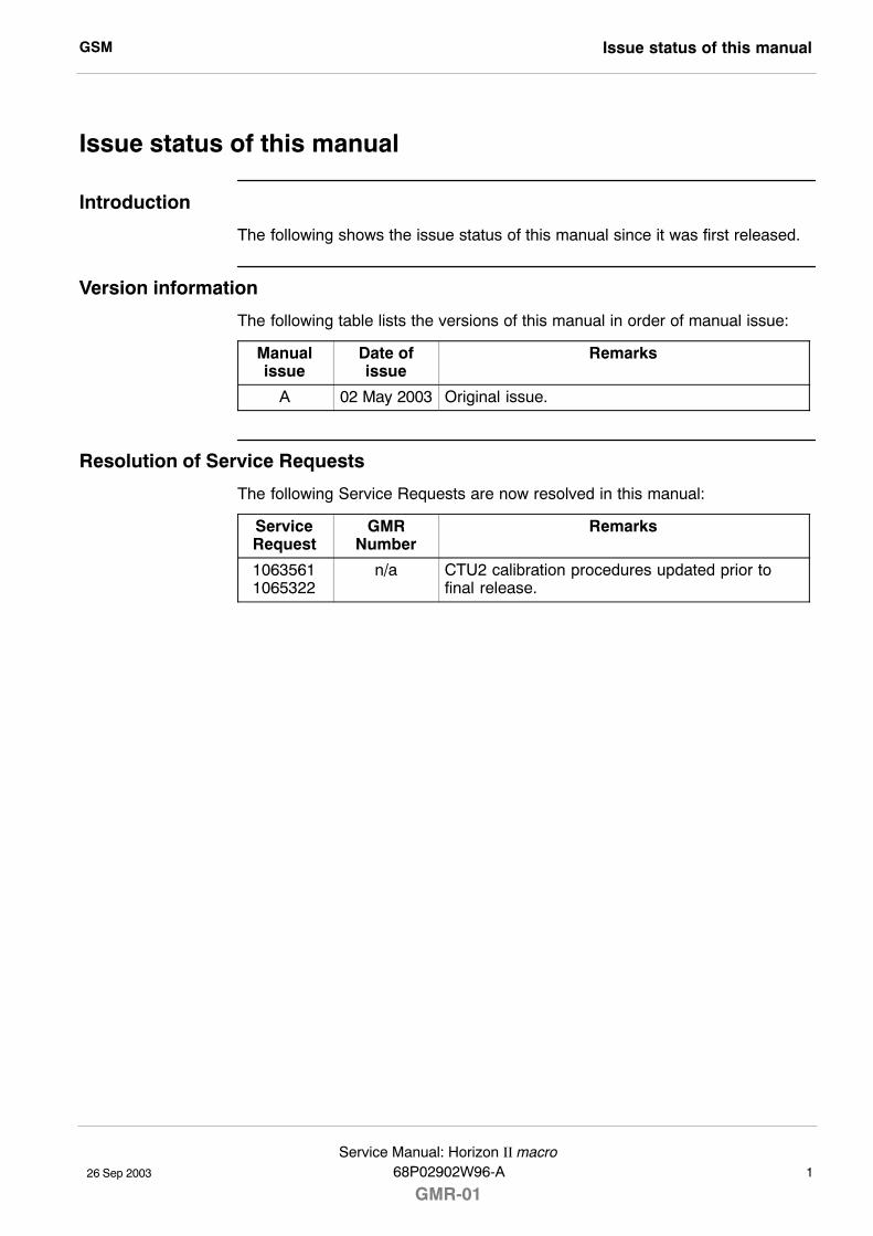
Issue status of this manual
Introduction
The following shows the issue status of this manual since it was first released.
Version information
The following table lists the versions of this manual in order of manual issue:
Manualissue
Date ofissue
Remarks
A 02 May 2003 Original issue.
Resolution of Service Requests
The following Service Requests are now resolved in this manual:
ServiceRequest
GMRNumber
Remarks
10635611065322
n/a CTU2 calibration procedures updated prior tofinal release.
GSMGeneral information
26 Sep 20032Service Manual: Horizon II macro
GMR-0168P02902W96-A
General information
Important notice
If this manual was obtained when attending a Motorola training course, it will notbe updated or amended by Motorola. It is intended for TRAINING PURPOSESONLY. If it was supplied under normal operational circumstances, to support amajor software release, then corrections will be supplied automatically byMotorola in the form of General Manual Revisions (GMRs).
Purpose
Motorola cellular communications manuals are intended to instruct and assistpersonnel in the operation, installation and maintenance of the Motorola cellularinfrastructure equipment and ancillary devices. It is recommended that allpersonnel engaged in such activities be properly trained by Motorola.
WARNING Failure to comply with Motorola�s operation, installationand maintenance instructions may, in exceptionalcircumstances, lead to serious injury or death.
These manuals are not intended to replace the system and equipment trainingoffered by Motorola, although they can be used to supplement and enhance theknowledge gained through such training.
About this manual
The manual contains technical descriptions of the hardware elements and repairprocedures and parts lists for the Horizon II macro equipment.
The objectives of this manual are to help the reader:
S Gain an overview of the equipment and interconnection of components.
S Understand the function and operation of all components.
S Recognize configurations and equivalent module functions to previouscabinet designs (M-Cell6 and Horizonmacro).
S Understand how to inspect, maintain, and repair the equipment.
S Be aware of the warnings (potential for harm to people) and cautions(potential for harm to equipment) to be observed when working on theequipment.
S Have a clear ready reference for all dedicated information in one manual.
NOTE For installation and commissioning information refer toInstallation and Configuration, Horizon II macro,68P02902W97 .
GSM General information
26 Sep 2003
Service Manual: Horizon II macro68P02902W96-A
GMR-013
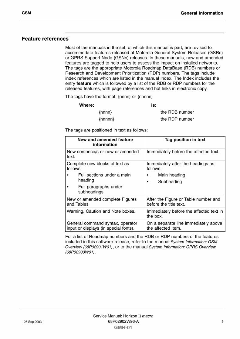
Feature references
Most of the manuals in the set, of which this manual is part, are revised toaccommodate features released at Motorola General System Releases (GSRn)or GPRS Support Node (GSNn) releases. In these manuals, new and amendedfeatures are tagged to help users to assess the impact on installed networks.The tags are the appropriate Motorola Roadmap DataBase (RDB) numbers orResearch and Development Prioritization (RDP) numbers. The tags includeindex references which are listed in the manual Index. The Index includes theentry feature which is followed by a list of the RDB or RDP numbers for thereleased features, with page references and hot links in electronic copy.
The tags have the format: {nnnn} or {nnnnn}
Where: is:
{nnnn} the RDB number
{nnnnn} the RDP number
The tags are positioned in text as follows:
New and amended featureinformation
Tag position in text
New sentence/s or new or amendedtext.
Immediately before the affected text.
Complete new blocks of text asfollows:S Full sections under a main
heading
S Full paragraphs undersubheadings
Immediately after the headings asfollows:S Main heading
S Subheading
New or amended complete Figuresand Tables
After the Figure or Table number andbefore the title text.
Warning, Caution and Note boxes. Immediately before the affected text inthe box.
General command syntax, operatorinput or displays (in special fonts).
On a separate line immediately abovethe affected item.
For a list of Roadmap numbers and the RDB or RDP numbers of the featuresincluded in this software release, refer to the manual System Information: GSMOverview (68P02901W01), or to the manual System Information: GPRS Overview(68P02903W01).
GSMGeneral information
26 Sep 20034Service Manual: Horizon II macro
GMR-0168P02902W96-A
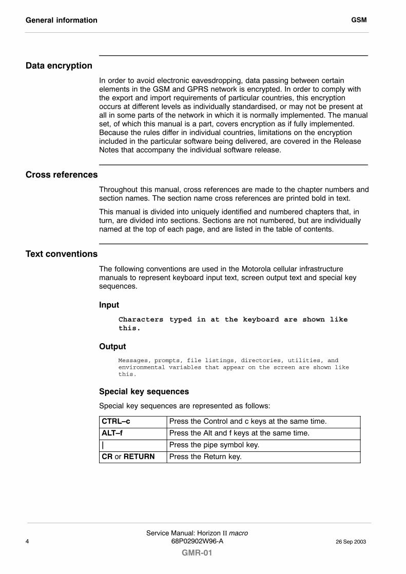
Data encryption
In order to avoid electronic eavesdropping, data passing between certainelements in the GSM and GPRS network is encrypted. In order to comply withthe export and import requirements of particular countries, this encryptionoccurs at different levels as individually standardised, or may not be present atall in some parts of the network in which it is normally implemented. The manualset, of which this manual is a part, covers encryption as if fully implemented.Because the rules differ in individual countries, limitations on the encryptionincluded in the particular software being delivered, are covered in the ReleaseNotes that accompany the individual software release.
Cross references
Throughout this manual, cross references are made to the chapter numbers andsection names. The section name cross references are printed bold in text.
This manual is divided into uniquely identified and numbered chapters that, inturn, are divided into sections. Sections are not numbered, but are individuallynamed at the top of each page, and are listed in the table of contents.
Text conventions
The following conventions are used in the Motorola cellular infrastructuremanuals to represent keyboard input text, screen output text and special keysequences.
Input
Characters typed in at the keyboard are shown likethis.
Output
Messages, prompts, file listings, directories, utilities, andenvironmental variables that appear on the screen are shown likethis.
Special key sequences
Special key sequences are represented as follows:
CTRL�c Press the Control and c keys at the same time.
ALT�f Press the Alt and f keys at the same time.
| Press the pipe symbol key.
CR or RETURN Press the Return key.
GSM Reporting safety issues
26 Sep 2003
Service Manual: Horizon II macro68P02902W96-A
GMR-015
Reporting safety issues
Introduction
Whenever a safety issue arises, carry out the following procedure in allinstances. Ensure that all site personnel are familiar with this procedure.
Procedure
Whenever a safety issue arises:
1. Make the equipment concerned safe, for example by removing power.
2. Make no further attempt to adjust or rectify the equipment.
3. Report the problem directly to the Customer Network Resolution Centre,Swindon +44 (0)1793 565444 or China +86 10 68437733 (telephone) andfollow up with a written report by fax, Swindon +44 (0)1793 430987 orChina +86 10 68423633 (fax).
4. Collect evidence from the equipment under the guidance of the CustomerNetwork Resolution Centre.
GSMWarnings and cautions
26 Sep 20036Service Manual: Horizon II macro
GMR-0168P02902W96-A
Warnings and cautions
Introduction
The following describes how warnings and cautions are used in this manual andin all manuals of this Motorola manual set.
Warnings
Definition of Warning
A warning is used to alert the reader to possible hazards that could cause lossof life, physical injury, or ill health. This includes hazards introduced duringmaintenance, for example, the use of adhesives and solvents, as well as thoseinherent in the equipment.
Example and format
WARNING Do not look directly into fibre optic cables or data in/outconnectors. Laser radiation can come from either the datain/out connectors or unterminated fibre optic cablesconnected to data in/out connectors.
Failure to comply with warnings
Observe all warnings during all phases of operation, installation andmaintenance of the equipment described in the Motorola manuals. Failure tocomply with these warnings, or with specific warnings elsewhere in theMotorola manuals, or on the equipment itself, violates safety standards ofdesign, manufacture and intended use of the equipment. Motorolaassumes no liability for the customer�s failure to comply with theserequirements.
Cautions
Definition of Caution
A caution means that there is a possibility of damage to systems, software orindividual items of equipment within a system. However, this presents no dangerto personnel.
Example and format
CAUTION Do not use test equipment that is beyond its duecalibration date; arrange for calibration to be carried out.
GSM General warnings
26 Sep 2003
Service Manual: Horizon II macro68P02902W96-A
GMR-017
General warnings
Introduction
Observe the following specific warnings during all phases of operation,installation and maintenance of the equipment described in the Motorolamanuals:
S Potentially hazardous voltage
S Electric shock
S RF radiation
S Laser radiation
S Heavy equipment
S Parts substitution
S Battery supplies
S Lithium batteries
Failure to comply with these warnings, or with specific warnings elsewhere in theMotorola manuals, violates safety standards of design, manufacture andintended use of the equipment. Motorola assumes no liability for the customer�sfailure to comply with these requirements.
Warning labels
Warnings particularly applicable to the equipment are positioned on theequipment. Personnel working with or operating Motorola equipment mustcomply with any warning labels fitted to the equipment. Warning labels must notbe removed, painted over or obscured in any way.
GSMGeneral warnings
26 Sep 20038Service Manual: Horizon II macro
GMR-0168P02902W96-A
Specific warnings
Specific warnings used throughout the GSM manual set are shown below.These will be incorporated into procedures as applicable.
These must be observed by all personnel at all times when working with theequipment, as must any other warnings given in text, in the illustrations and onthe equipment.
Potentially hazardous voltage
WARNING This equipment operates from a hazardous voltage of230 V ac single phase or 415 V ac three phase supply. Toachieve isolation of the equipment from the ac supply, theac input isolator must be set to off and locked.
When working with electrical equipment, reference must be made to theElectricity at Work Regulations 1989 (UK), or to the relevant electricity at worklegislation for the country in which the equipment is used.
NOTE Motorola GSM equipment does not utilise high voltages.
Electric shock
WARNING Do not touch the victim with your bare hands until theelectric circuit is broken.Switch off. If this is not possible, protect yourself with dryinsulating material and pull or push the victim clear of theconductor.ALWAYS send for trained first aid or medical assistanceIMMEDIATELY.
In cases of low voltage electric shock (including public supply voltages), seriousinjuries and even death, may result. Direct electrical contact can stun a casualtycausing breathing, and even the heart, to stop. It can also cause skin burns atthe points of entry and exit of the current.
In the event of an electric shock it may be necessary to carry out artificialrespiration. ALWAYS send for trained first aid or medical assistanceIMMEDIATELY.
If the casualty is also suffering from burns, flood the affected area with coldwater to cool, until trained first aid or medical assistance arrives.
GSM General warnings
26 Sep 2003
Service Manual: Horizon II macro68P02902W96-A
GMR-019
RF radiation
WARNING High RF potentials and electromagnetic fields are presentin this equipment when in operation. Ensure that alltransmitters are switched off when any antennaconnections have to be changed. Do not key transmittersconnected to unterminated cavities or feeders.
Relevant standards (USA and EC), to which regard should be paid whenworking with RF equipment are:
S ANSI IEEE C95.1-1991, IEEE Standard for Safety Levels with Respect toHuman Exposure to Radio Frequency Electromagnetic Fields, 3 kHz to300 GHz.
S CENELEC 95 ENV 50166-2, Human Exposure to Electromagnetic FieldsHigh Frequency (10 kHz to 300 GHz).
Laser radiation
WARNING Do not look directly into fibre optic cables or optical datain/out connectors. Laser radiation can come from eitherthe data in/out connectors or unterminated fibre opticcables connected to data in/out connectors.
Lifting equipment
WARNING When dismantling heavy assemblies, or removing orreplacing equipment, a competent responsible personmust ensure that adequate lifting facilities are available.Where provided, lifting frames must be used for theseoperations.
When dismantling heavy assemblies, or removing or replacing equipment, thecompetent responsible person must ensure that adequate lifting facilities areavailable. Where provided, lifting frames must be used for these operations.When equipments have to be manhandled, reference must be made to theManual Handling of Loads Regulations 1992 (UK) or to the relevant manualhandling of loads legislation for the country in which the equipment is used.
GSMGeneral warnings
26 Sep 200310Service Manual: Horizon II macro
GMR-0168P02902W96-A
Parts substitution
WARNING Do not install substitute parts or perform any unauthorizedmodification of equipment, because of the danger ofintroducing additional hazards.Contact Motorola if in doubtto ensure that safety features are maintained.
Battery supplies
WARNING Do not wear earth straps when working with standbybattery supplies.
Lithium batteries
WARNING Lithium batteries, if subjected to mistreatment, may burstand ignite. Defective lithium batteries must not beremoved or replaced. Any boards containing defectivelithium batteries must be returned to Motorola for repair.
Contact your local Motorola office for how to return defective lithium batteries.
GSM General cautions
26 Sep 2003
Service Manual: Horizon II macro68P02902W96-A
GMR-0111
General cautions
Introduction
Observe the following cautions during operation, installation and maintenance ofthe equipment described in the Motorola manuals. Failure to comply with thesecautions or with specific cautions elsewhere in the Motorola manuals may resultin damage to the equipment. Motorola assumes no liability for the customer�sfailure to comply with these requirements.
Caution labels
Personnel working with or operating Motorola equipment must comply with anycaution labels fitted to the equipment. Caution labels must not be removed,painted over or obscured in any way.
Specific cautions
Cautions particularly applicable to the equipment are positioned within the textof this manual. These must be observed by all personnel at all times whenworking with the equipment, as must any other cautions given in text, on theillustrations and on the equipment.
Fibre optics
CAUTION Fibre optic cables must not be bent in a radius of less than30 mm.
Static discharge
CAUTION Motorola equipment contains CMOS devices. These metaloxide semiconductor (MOS) devices are susceptible todamage from electrostatic charge. See the sectionDevices sensitive to static in the preface of this manualfor further information.
GSMDevices sensitive to static
26 Sep 200312Service Manual: Horizon II macro
GMR-0168P02902W96-A
Devices sensitive to static
Introduction
Certain metal oxide semiconductor (MOS) devices embody in their design a thinlayer of insulation that is susceptible to damage from electrostatic charge. Sucha charge applied to the leads of the device could cause irreparable damage.
These charges can be built up on nylon overalls, by friction, by pushing thehands into high insulation packing material or by use of unearthed solderingirons.
MOS devices are normally despatched from the manufacturers with the leadsshorted together, for example, by metal foil eyelets, wire strapping, or byinserting the leads into conductive plastic foam. Provided the leads are shortedit is safe to handle the device.
Special handling techniques
In the event of one of these devices having to be replaced, observe thefollowing precautions when handling the replacement:
S Always wear an earth strap which must be connected to the electrostaticpoint (ESP) on the equipment.
S Leave the short circuit on the leads until the last moment. It may benecessary to replace the conductive foam by a piece of wire to enable thedevice to be fitted.
S Do not wear outer clothing made of nylon or similar man made material. Acotton overall is preferable.
S If possible work on an earthed metal surface or anti-static mat. Wipeinsulated plastic work surfaces with an anti-static cloth before starting theoperation.
S All metal tools should be used and when not in use they should be placedon an earthed surface.
S Take care when removing components connected to electrostatic sensitivedevices. These components may be providing protection to the device.
When mounted onto printed circuit boards (PCBs), MOS devices are normallyless susceptible to electrostatic damage. However PCBs should be handled withcare, preferably by their edges and not by their tracks and pins, they should betransferred directly from their packing to the equipment (or the other wayaround) and never left exposed on the workbench.
GSM Motorola manual set
26 Sep 2003
Service Manual: Horizon II macro68P02902W96-A
GMR-0113
Motorola manual set
Introduction
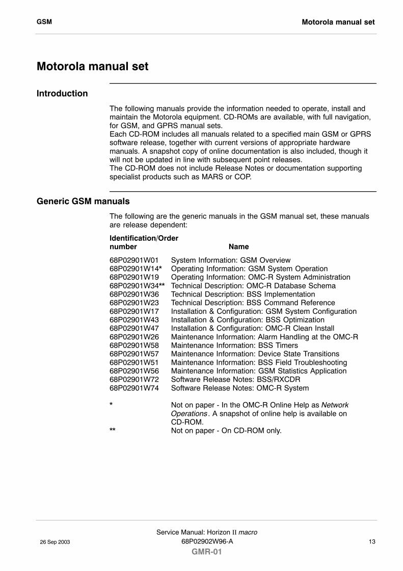
The following manuals provide the information needed to operate, install andmaintain the Motorola equipment. CD-ROMs are available, with full navigation,for GSM, and GPRS manual sets.Each CD-ROM includes all manuals related to a specified main GSM or GPRSsoftware release, together with current versions of appropriate hardwaremanuals. A snapshot copy of online documentation is also included, though itwill not be updated in line with subsequent point releases.The CD-ROM does not include Release Notes or documentation supportingspecialist products such as MARS or COP.
Generic GSM manuals
The following are the generic manuals in the GSM manual set, these manualsare release dependent:
Identification/Order number Name
68P02901W01 System Information: GSM Overview68P02901W14* Operating Information: GSM System Operation68P02901W19 Operating Information: OMC-R System Administration68P02901W34** Technical Description: OMC-R Database Schema68P02901W36 Technical Description: BSS Implementation68P02901W23 Technical Description: BSS Command Reference68P02901W17 Installation & Configuration: GSM System Configuration68P02901W43 Installation & Configuration: BSS Optimization68P02901W47 Installation & Configuration: OMC-R Clean Install68P02901W26 Maintenance Information: Alarm Handling at the OMC-R68P02901W58 Maintenance Information: BSS Timers68P02901W57 Maintenance Information: Device State Transitions68P02901W51 Maintenance Information: BSS Field Troubleshooting68P02901W56 Maintenance Information: GSM Statistics Application68P02901W72 Software Release Notes: BSS/RXCDR68P02901W74 Software Release Notes: OMC-R System
* Not on paper - In the OMC-R Online Help as Network Operations. A snapshot of online help is available on CD-ROM.
** Not on paper - On CD-ROM only.
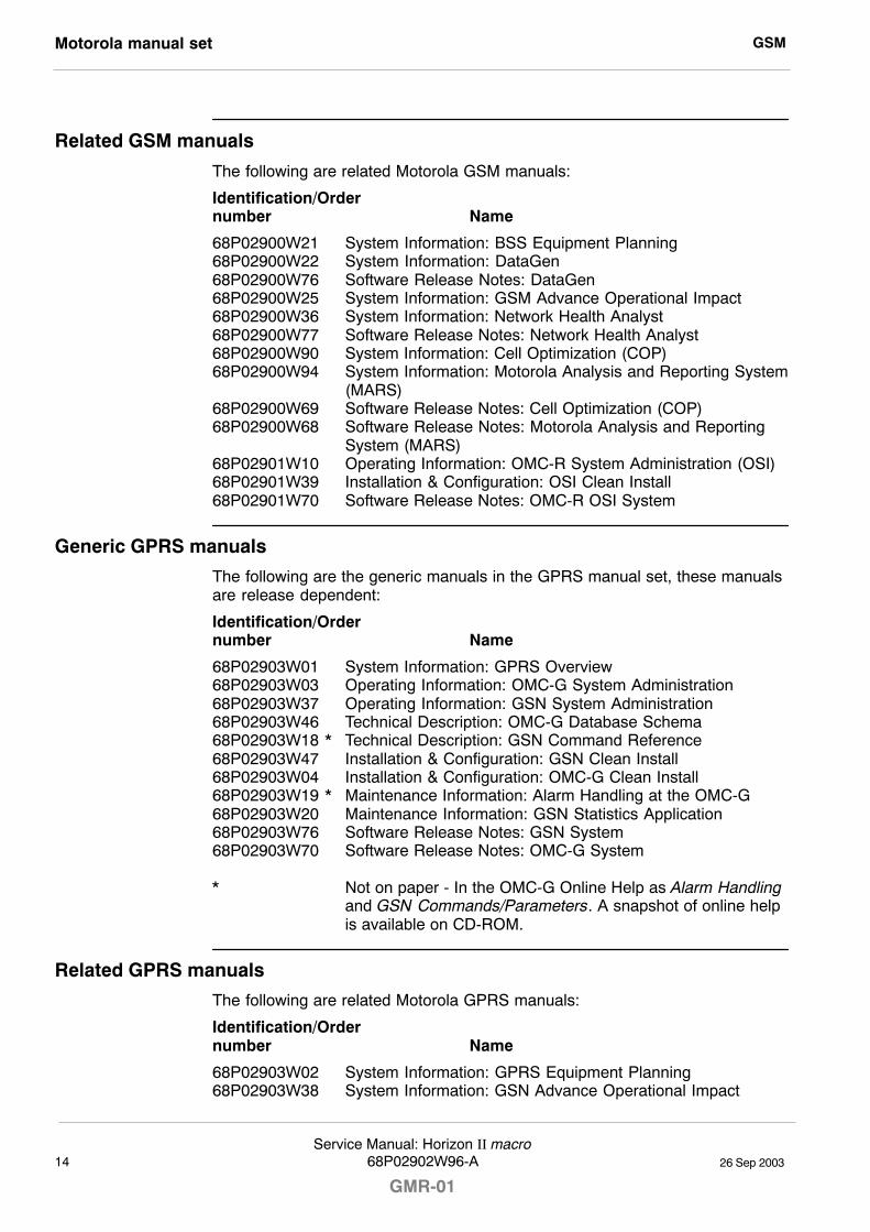
GSMMotorola manual set
26 Sep 200314Service Manual: Horizon II macro
GMR-0168P02902W96-A
Related GSM manuals
The following are related Motorola GSM manuals:
Identification/Order number Name
68P02900W21 System Information: BSS Equipment Planning68P02900W22 System Information: DataGen68P02900W76 Software Release Notes: DataGen68P02900W25 System Information: GSM Advance Operational Impact68P02900W36 System Information: Network Health Analyst68P02900W77 Software Release Notes: Network Health Analyst68P02900W90 System Information: Cell Optimization (COP)68P02900W94 System Information: Motorola Analysis and Reporting System
(MARS)68P02900W69 Software Release Notes: Cell Optimization (COP)68P02900W68 Software Release Notes: Motorola Analysis and Reporting
System (MARS)68P02901W10 Operating Information: OMC-R System Administration (OSI)68P02901W39 Installation & Configuration: OSI Clean Install68P02901W70 Software Release Notes: OMC-R OSI System
Generic GPRS manuals
The following are the generic manuals in the GPRS manual set, these manualsare release dependent:
Identification/Order number Name
68P02903W01 System Information: GPRS Overview68P02903W03 Operating Information: OMC-G System Administration68P02903W37 Operating Information: GSN System Administration68P02903W46 Technical Description: OMC-G Database Schema68P02903W18 * Technical Description: GSN Command Reference68P02903W47 Installation & Configuration: GSN Clean Install68P02903W04 Installation & Configuration: OMC-G Clean Install68P02903W19 * Maintenance Information: Alarm Handling at the OMC-G68P02903W20 Maintenance Information: GSN Statistics Application68P02903W76 Software Release Notes: GSN System68P02903W70 Software Release Notes: OMC-G System
* Not on paper - In the OMC-G Online Help as Alarm Handling and GSN Commands/Parameters. A snapshot of online help is available on CD-ROM.
Related GPRS manuals
The following are related Motorola GPRS manuals:
Identification/Order number Name
68P02903W02 System Information: GPRS Equipment Planning68P02903W38 System Information: GSN Advance Operational Impact
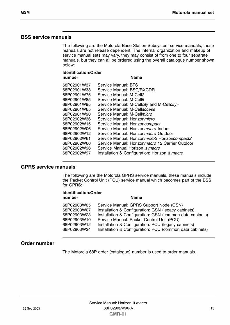
GSM Motorola manual set
26 Sep 2003
Service Manual: Horizon II macro68P02902W96-A
GMR-0115
BSS service manuals
The following are the Motorola Base Station Subsystem service manuals, thesemanuals are not release dependent. The internal organization and makeup ofservice manual sets may vary, they may consist of from one to four separatemanuals, but they can all be ordered using the overall catalogue number shownbelow:
Identification/Order number Name
68P02901W37 Service Manual: BTS68P02901W38 Service Manual: BSC/RXCDR68P02901W75 Service Manual: M-Cell268P02901W85 Service Manual: M-Cell668P02901W95 Service Manual: M-Cellcity and M-Cellcity+68P02901W65 Service Manual: M-Cellaccess68P02901W90 Service Manual: M-Cellmicro68P02902W36 Service Manual: Horizonmicro68P02902W15 Service Manual: Horizoncompact68P02902W06 Service Manual: Horizonmacro Indoor68P02902W12 Service Manual: Horizonmacro Outdoor68P02902W61 Service Manual: Horizonmicro2 Horizoncompact268P02902W66 Service Manual: Horizonmacro 12 Carrier Outdoor68P02902W96 Service Manual:Horizon II macro68P02902W97 Installation & Configuration: Horizon II macro
GPRS service manuals
The following are the Motorola GPRS service manuals, these manuals includethe Packet Control Unit (PCU) service manual which becomes part of the BSSfor GPRS:
Identification/Order number Name
68P02903W05 Service Manual: GPRS Support Node (GSN)68P02903W07 Installation & Configuration: GSN (legacy cabinets)68P02903W23 Installation & Configuration: GSN (common data cabinets)68P02903W10 Service Manual: Packet Control Unit (PCU)68P02903W12 Installation & Configuration: PCU (legacy cabinets)68P02903W24 Installation & Configuration: PCU (common data cabinets)
Order number
The Motorola 68P order (catalogue) number is used to order manuals.
GSMMotorola manual set
26 Sep 200316Service Manual: Horizon II macro
GMR-0168P02902W96-A
Ordering manuals
All orders for Motorola manuals must be placed with your Motorola Local Officeor Representative. Manuals are ordered using the order (catalogue) number.
Manuals are available on the following media:
Printed hard copy
Electronic:
S On the Motorola service web.
S CD-ROM library produced in support of a major system software release.
GSM GMR amendment
26 Sep 2003
Service Manual: Horizon II macro68P02902W96-A
GMR-0117
GMR amendment
Introduction to GMRs
Changes to a manual that occur after the printing date are incorporated into themanual using General Manual Revisions (GMRs). GMRs are issued to correctMotorola manuals as and when required. A GMR has the same identity as thetarget manual. Each GMR is identified by a number in a sequence that starts at01 for each manual at each issue.
GMR availability
GMRs are published as follows:
S Printed hard copy - Complete replacement content or loose leaf pageswith amendment list.
� Remove and replace pages in this manual, as detailed on the GMRinstruction sheet.
S Motorola service web - Updated at the same time as hard copies.
S CD-ROM - Updated periodically as required.
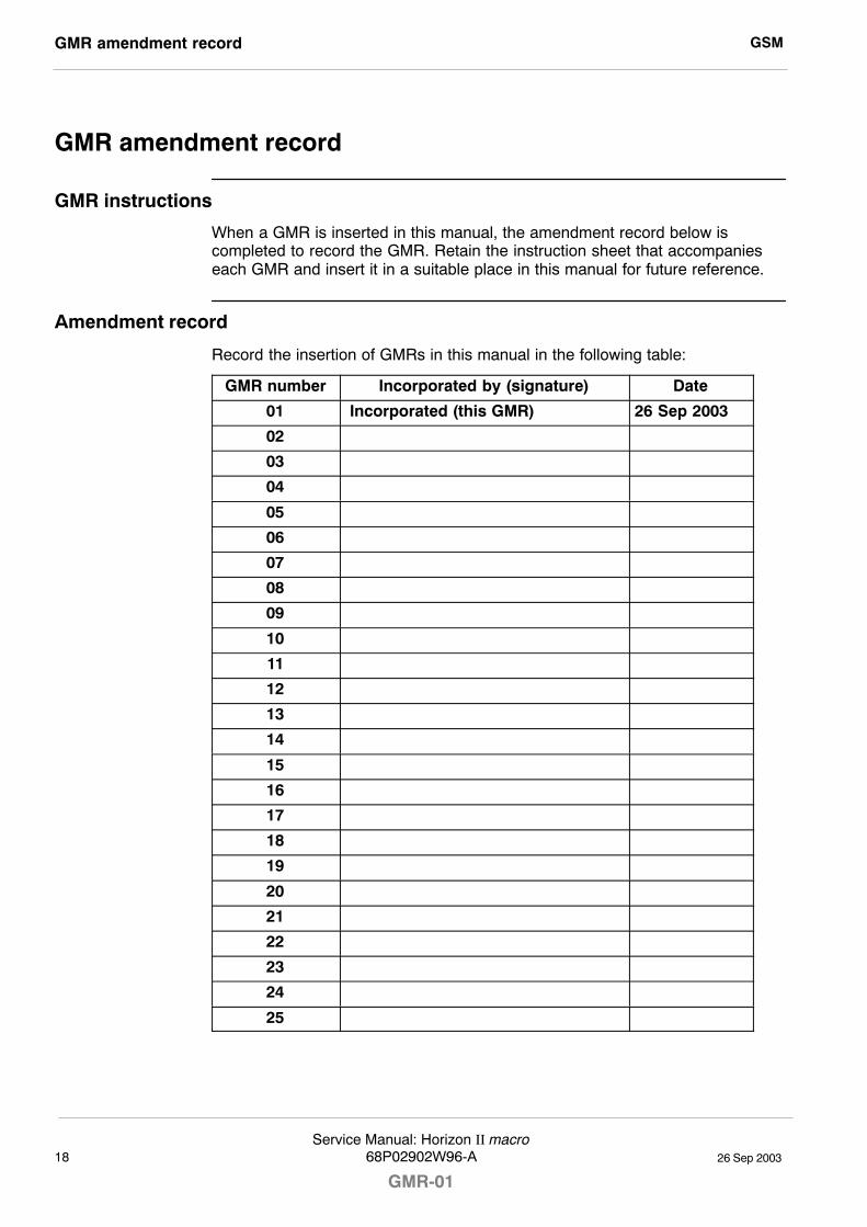
GSMGMR amendment record
26 Sep 200318Service Manual: Horizon II macro
GMR-0168P02902W96-A
GMR amendment record
GMR instructions
When a GMR is inserted in this manual, the amendment record below iscompleted to record the GMR. Retain the instruction sheet that accompanieseach GMR and insert it in a suitable place in this manual for future reference.
Amendment record
Record the insertion of GMRs in this manual in the following table:
GMR number Incorporated by (signature) Date
01 .Incorporated (this GMR) 26 Sep 2003
02
03
04
05
06
07
08
09
10
11
12
13
14
15
16
17
18
19
20
21
22
23
24
25

CHAPTER 2CABINET STRUCTURE
CHAPTER 3POWER DISTRIBUTION
CHAPTER 4RF MODULES
CHAPTER 5DIGITAL MODULES
CHAPTER 1 EQUIPMENT INTRODUCTION
AND SPECIFICATIONS


26 Sep 2003
Technical Description: Horizon II macro
68P02902W96-A
GMR-01i
Technical Description (Tech.)

GSM
26 Sep 2003ii
Technical Description: Horizon II macro
GMR-0168P02902W96-A
26 Sep 2003
Technical Description: Horizon II macro
68P02902W96-A
GMR-01Tech. 1�1
Chapter 1
Introduction to the
Horizon II macro

GSM
26 Sep 2003Tech. 1�2
Technical Description: Horizon II macro
GMR-0168P02902W96-A
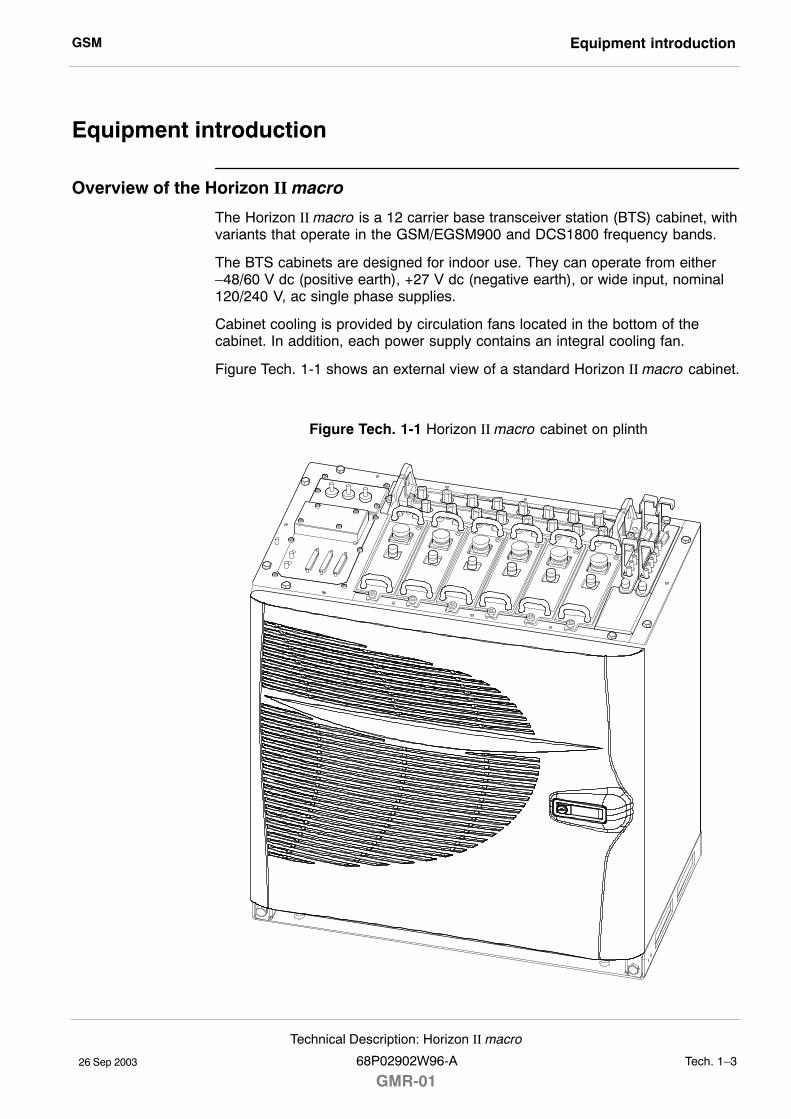
GSM Equipment introduction
26 Sep 2003
Technical Description: Horizon II macro
68P02902W96-A
GMR-01Tech. 1�3
Equipment introduction
Overview of the Horizon II macro
The Horizon II macro is a 12 carrier base transceiver station (BTS) cabinet, withvariants that operate in the GSM/EGSM900 and DCS1800 frequency bands.
The BTS cabinets are designed for indoor use. They can operate from either�48/60 V dc (positive earth), +27 V dc (negative earth), or wide input, nominal120/240 V, ac single phase supplies.
Cabinet cooling is provided by circulation fans located in the bottom of thecabinet. In addition, each power supply contains an integral cooling fan.
Figure Tech. 1-1 shows an external view of a standard Horizon II macro cabinet.
Figure Tech. 1-1 Horizon II macro cabinet on plinth
GSMEquipment introduction
26 Sep 2003Tech. 1�4
Technical Description: Horizon II macro
GMR-0168P02902W96-A
Finding information in this manual
A full table of contents (TOC) is provided at the front of this manual. Headingsare designed to convey contents accurately, to simplify searching for specificinformation. The index at the back of the manual provides an alternative methodof finding subsections of information. This chapter provides a summary of theequipment, to enable readers to understand terminology and thus locateinformation via the TOC and index.
The service manual comprises two main sections:
S Technical Description
Provides an introduction, specifications, and technical descriptions of allHorizon II macro components.
S Maintenance and Parts
Provides information on maintenance and repair, with procedures tochange field replaceable units (FRUs). Lists of options and spares, withdiagrams to illustrate FRUs, are also included.
Each section is divided into chapters. The information in each chapter isgrouped according to functionality, as shown in Figure Tech. 1-2.
NOTE Installation information for the Horizon II macro is notprovided in this manual (refer to Horizon II macro:Installation and Configuration, 68P02902W97 forinstallation and configuration information).
GSM Equipment introduction
26 Sep 2003
Technical Description: Horizon II macro
68P02902W96-A
GMR-01Tech. 1�5
Names and acronyms for main cabinet equipment
This section provides an overview of the equipment in the Horizon II macrocabinet.
The Horizon II macro cabinet consists of the cabinet frame structure (includingdoor), a main cage with integrated backplane and a top panel. It contains thefollowing equipment, as shown in Figure Tech. 1-2, listed from the base up:
S Plinth.This secures the cabinet firmly to the floor (or to the stacking bracket in astacked configuration).
S Fan module (x3).These provide cooling for the cabinet, and especially for the CTU2transceivers and digital modules mounted directly above.
S Power supply unit (PSU).The PSUs are load sharing. In a fully equipped cabinet, a fourth PSUprovides 3 + 1 redundancy. The PSUs contain integral cooling fans.
S Circuit breaker card (CBC).The CBC provides circuit protection and the facility to manually isolateindividual modules within the Horizon II macro cabinet.
S Compact transceiver unit (CTU2).Provides amplification and signal conditioning for outgoing (Tx) signalsand receives Rx signals from the SURF2. The CTU2 provides 2 x GSM/GPRS and 1 x EDGE capability. It is backwards compatible with theHorizonmacro CTU (with BBH limitations in double density form). Up to sixCTU2s may be fitted in the cabinet to provide 12 GSM/GPRS carriers(double density).
S Alarm module.This handles all cabinet alarm I/O signals and provides current sensing forexternal site alarms (via the PIX connectors).
S Site controller unit (HIISC).Provides the site processing functions for the BTS (equivalent to theMCUF in Horizonmacro). Includes an integrated XMUX and NIU. Provisionis made for an additional HIISC to be fitted, if redundancy is required.
S Expansion multiplexer module (XMUX).An optional module that replaces the site controller unit in an expansion(slave) cabinet to provide multiplexer connections to the master cabinet.An additional XMUX can be installed if redundancy is required.
S Power distribution assembly (PDA).Mounted on the left side of the top panel assembly. Provides theconnectors for ac or dc power input. Also contains the interface panel forcustomer communications connectors.
S Sectorized universal receiver front end (SURF2) module.Mounted at the rear of the top panel assembly. Provides amplification andsignal conditioning functions for incoming (Rx) signals. One or twoSURF2s may be fitted to provide 2 or 4 branch receive diversity.
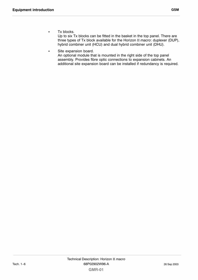
GSMEquipment introduction
26 Sep 2003Tech. 1�6
Technical Description: Horizon II macro
GMR-0168P02902W96-A
S Tx blocks.Up to six Tx blocks can be fitted in the basket in the top panel. There arethree types of Tx block available for the Horizon II macro: duplexer (DUP),hybrid combiner unit (HCU) and dual hybrid combiner unit (DHU).
S Site expansion board.An optional module that is mounted in the right side of the top panelassembly. Provides fibre optic connections to expansion cabinets. Anadditional site expansion board can be installed if redundancy is required.
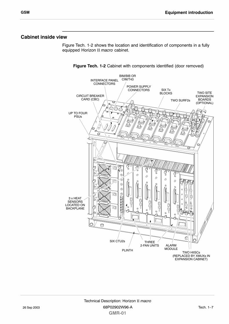
GSM Equipment introduction
26 Sep 2003
Technical Description: Horizon II macro
68P02902W96-A
GMR-01Tech. 1�7
Cabinet inside view
Figure Tech. 1-2 shows the location and identification of components in a fullyequipped Horizon II macro cabinet.
Figure Tech. 1-2 Cabinet with components identified (door removed)
CIRCUIT BREAKERCARD (CBC)
TWO HIISCs(REPLACED BY XMUXs IN
EXPANSION CABINET)
ALARMMODULE
THREE2-FAN UNITS
SIX CTU2s
SIX TxBLOCKS
TWO SURF2s
TWO SITEEXPANSION
BOARDS(OPTIONAL)
3 x HEATSENSORS
LOCATED ONBACKPLANE
UP TO FOURPSUs
PLINTH
POWER SUPPLYCONNECTORS
INTERFACE PANELCONNECTORS
BIM/BIB ORCIM/T43
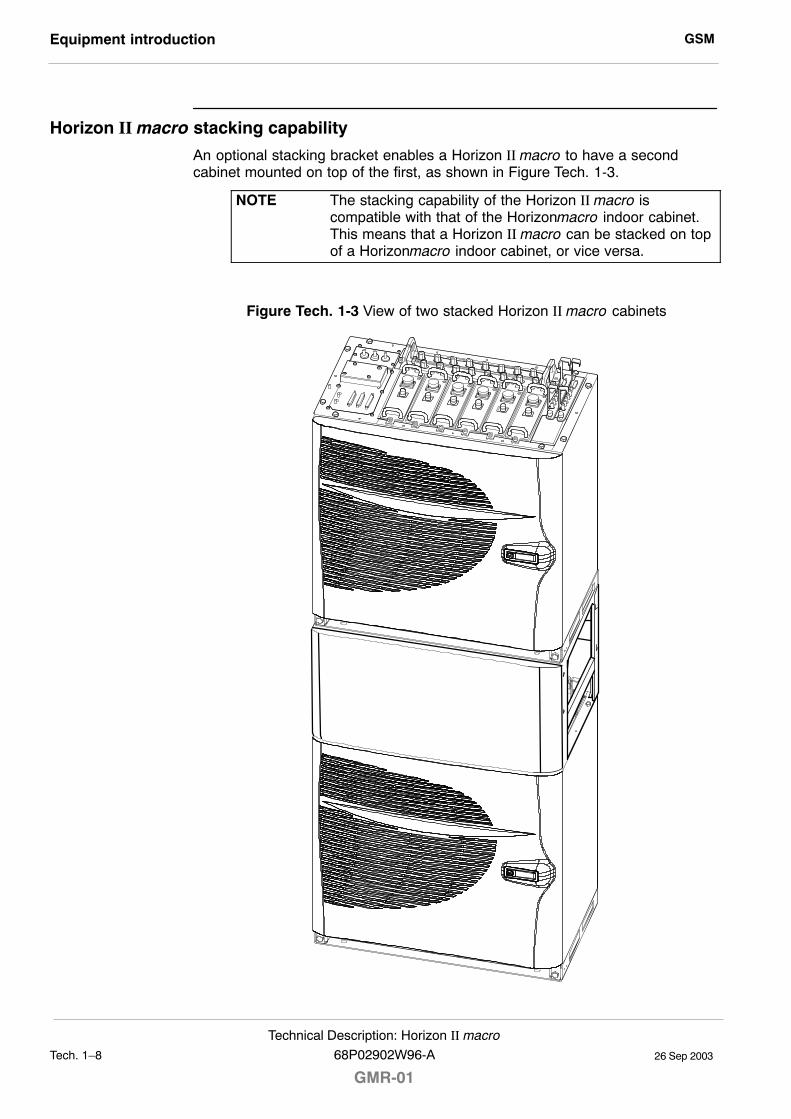
GSMEquipment introduction
26 Sep 2003Tech. 1�8
Technical Description: Horizon II macro
GMR-0168P02902W96-A
Horizon II macro stacking capability
An optional stacking bracket enables a Horizon II macro to have a secondcabinet mounted on top of the first, as shown in Figure Tech. 1-3.
NOTE The stacking capability of the Horizon II macro iscompatible with that of the Horizonmacro indoor cabinet.This means that a Horizon II macro can be stacked on topof a Horizonmacro indoor cabinet, or vice versa.
Figure Tech. 1-3 View of two stacked Horizon II macro cabinets
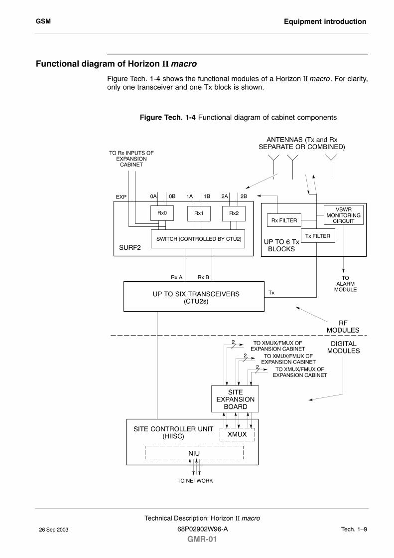
GSM Equipment introduction
26 Sep 2003
Technical Description: Horizon II macro
68P02902W96-A
GMR-01Tech. 1�9
Functional diagram of Horizon II macro
Figure Tech. 1-4 shows the functional modules of a Horizon II macro. For clarity,only one transceiver and one Tx block is shown.
Figure Tech. 1-4 Functional diagram of cabinet components
2
2
2
SWITCH (CONTROLLED BY CTU2)
SITE CONTROLLER UNIT(HIISC)
SITEEXPANSION
BOARD
XMUX
TO NETWORK
RFMODULES
DIGITALMODULES
UP TO SIX TRANSCEIVERS(CTU2s)
UP TO 6 TxBLOCKS
ANTENNAS (Tx and RxSEPARATE OR COMBINED)
SURF2
Rx0 Rx2Rx1
Rx A Rx B
Tx
TO Rx INPUTS OFEXPANSION
CABINET
Tx FILTER
Rx FILTER
TOALARM
MODULE
EXP
TO XMUX/FMUX OFEXPANSION CABINET
0B 1B1A 2A 2B0A
TO XMUX/FMUX OFEXPANSION CABINET
TO XMUX/FMUX OFEXPANSION CABINET
NIU
VSWRMONITORING
CIRCUIT
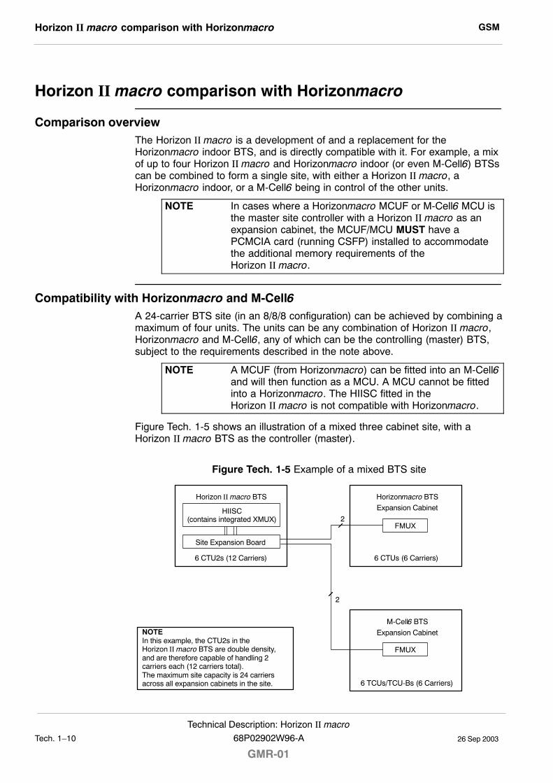
GSMHorizon II macro comparison with Horizonmacro
26 Sep 2003Tech. 1�10
Technical Description: Horizon II macro
GMR-0168P02902W96-A
Horizon II macro comparison with Horizonmacro
Comparison overviewThe Horizon II macro is a development of and a replacement for theHorizonmacro indoor BTS, and is directly compatible with it. For example, a mixof up to four Horizon II macro and Horizonmacro indoor (or even M-Cell6) BTSscan be combined to form a single site, with either a Horizon II macro, aHorizonmacro indoor, or a M-Cell6 being in control of the other units.
NOTE In cases where a Horizonmacro MCUF or M-Cell6 MCU isthe master site controller with a Horizon II macro as anexpansion cabinet, the MCUF/MCU MUST have aPCMCIA card (running CSFP) installed to accommodatethe additional memory requirements of theHorizon II macro.
Compatibility with Horizonmacro and M-Cell6A 24-carrier BTS site (in an 8/8/8 configuration) can be achieved by combining amaximum of four units. The units can be any combination of Horizon II macro,Horizonmacro and M-Cell6, any of which can be the controlling (master) BTS,subject to the requirements described in the note above.
NOTE A MCUF (from Horizonmacro) can be fitted into an M-Cell6and will then function as a MCU. A MCU cannot be fittedinto a Horizonmacro. The HIISC fitted in theHorizon II macro is not compatible with Horizonmacro.
Figure Tech. 1-5 shows an illustration of a mixed three cabinet site, with aHorizon II macro BTS as the controller (master).
Figure Tech. 1-5 Example of a mixed BTS site
2
2
Horizon II macro BTS
HIISC(contains integrated XMUX)
6 CTU2s (12 Carriers)
Horizonmacro BTS
6 CTUs (6 Carriers)
Expansion Cabinet
M-Cell6 BTS
6 TCUs/TCU-Bs (6 Carriers)
Expansion Cabinet
Site Expansion Board
NOTEIn this example, the CTU2s in theHorizon II macro BTS are double density,and are therefore capable of handling 2carriers each (12 carriers total).The maximum site capacity is 24 carriersacross all expansion cabinets in the site.
FMUX
FMUX
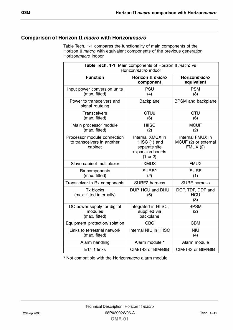
GSM Horizon II macro comparison with Horizonmacro
26 Sep 2003
Technical Description: Horizon II macro
68P02902W96-A
GMR-01Tech. 1�11
Comparison of Horizon II macro with Horizonmacro
Table Tech. 1-1 compares the functionality of main components of theHorizon II macro with equivalent components of the previous generationHorizonmacro indoor.
Table Tech. 1-1 Main components of Horizon II macro vs Horizonmacro indoor
Function Horizon II macrocomponent
Horizonmacroequivalent
Input power conversion units(max. fitted)
PSU(4)
PSM(3)
Power to transceivers andsignal routeing
Backplane BPSM and backplane
Transceivers(max. fitted)
CTU2(6)
CTU(6)
Main processor module(max. fitted)
HIISC(2)
MCUF(2)
Processor module connectionto transceivers in another
cabinet
Internal XMUX inHIISC (1) andseparate site
expansion boards(1 or 2)
Internal FMUX inMCUF (2) or external
FMUX (2)
Slave cabinet multiplexer XMUX FMUX
Rx components(max. fitted)
SURF2(2)
SURF(1)
Transceiver to Rx components SURF2 harness SURF harness
Tx blocks(max. fitted internally)
DUP, HCU and DHU(6)
DCF, TDF, DDF andHCU(3)
DC power supply for digitalmodules
(max. fitted)
Integrated in HIISC,supplied viabackplane
BPSM(2)
Equipment protection/isolation CBC CBM
Links to terrestrial network(max. fitted)
Internal NIU in HIISC NIU(4)
Alarm handling Alarm module * Alarm module
E1/T1 links CIM/T43 or BIM/BIB CIM/T43 or BIM/BIB
* Not compatible with the Horizonmacro alarm module.
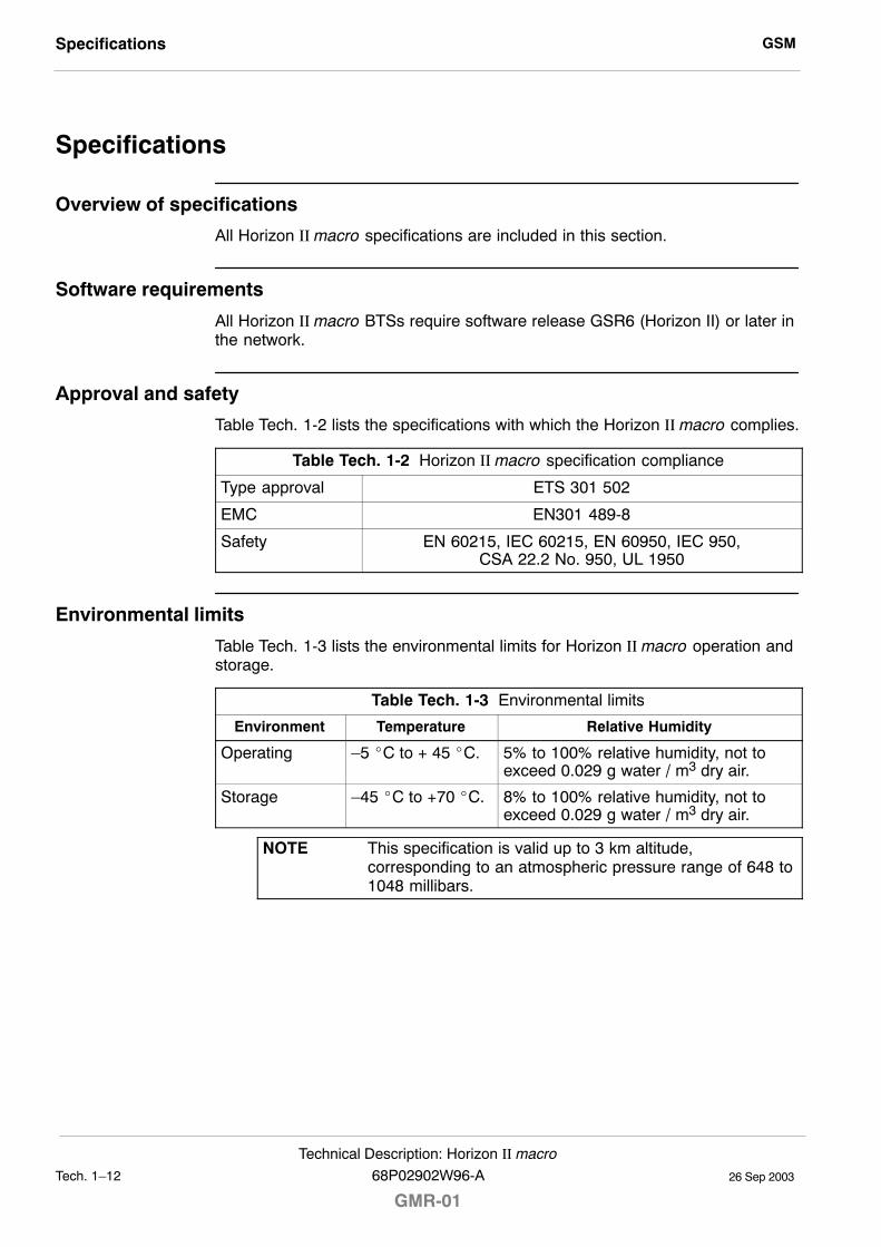
GSMSpecifications
26 Sep 2003Tech. 1�12
Technical Description: Horizon II macro
GMR-0168P02902W96-A
Specifications
Overview of specifications
All Horizon II macro specifications are included in this section.
Software requirements
All Horizon II macro BTSs require software release GSR6 (Horizon II) or later inthe network.
Approval and safety
Table Tech. 1-2 lists the specifications with which the Horizon II macro complies.
Table Tech. 1-2 Horizon II macro specification compliance
Type approval ETS 301 502
EMC EN301 489-8
Safety EN 60215, IEC 60215, EN 60950, IEC 950,CSA 22.2 No. 950, UL 1950
Environmental limits
Table Tech. 1-3 lists the environmental limits for Horizon II macro operation andstorage.
Table Tech. 1-3 Environmental limits
Environment Temperature Relative Humidity
Operating �5 _C to + 45 _C. 5% to 100% relative humidity, not toexceed 0.029 g water / m3 dry air.
Storage �45 _C to +70 _C. 8% to 100% relative humidity, not toexceed 0.029 g water / m3 dry air.
NOTE This specification is valid up to 3 km altitude,corresponding to an atmospheric pressure range of 648 to1048 millibars.
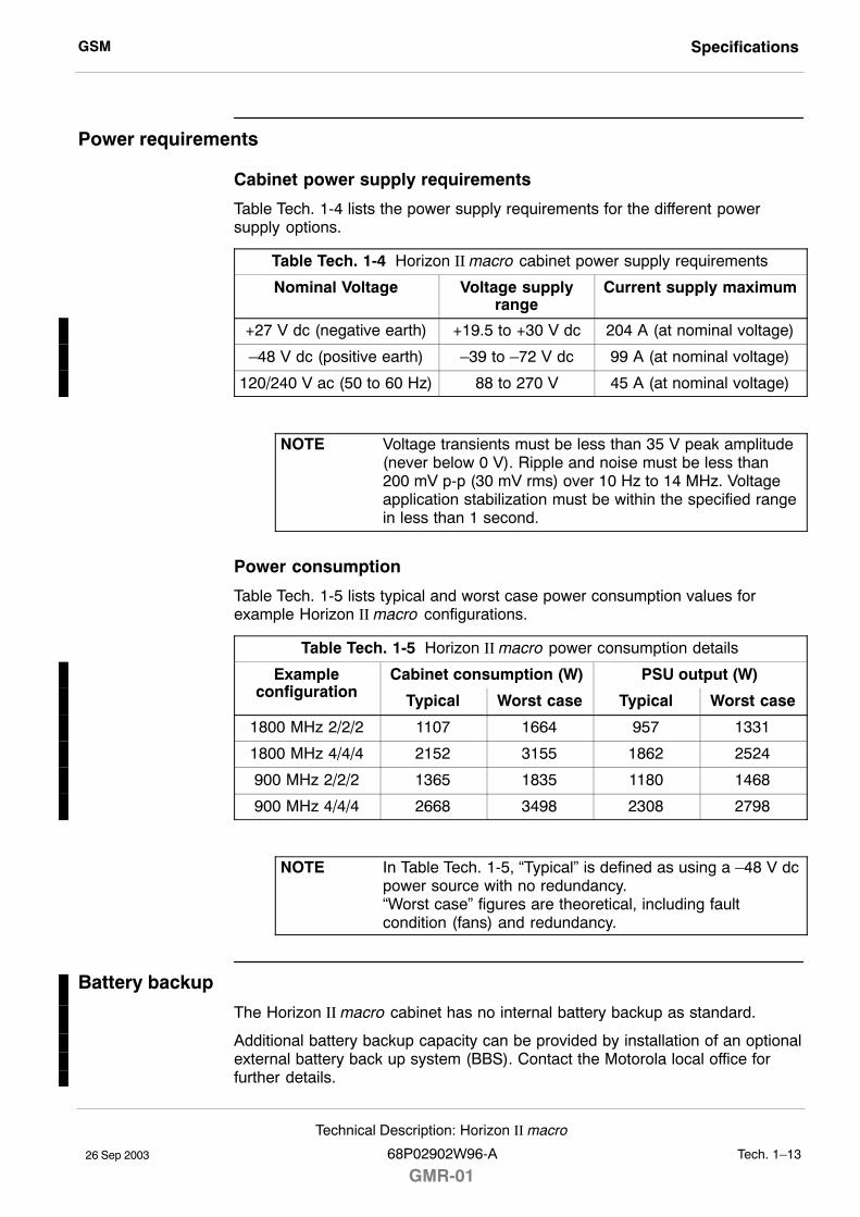
GSM Specifications
26 Sep 2003
Technical Description: Horizon II macro
68P02902W96-A
GMR-01Tech. 1�13
Power requirements
Cabinet power supply requirements
Table Tech. 1-4 lists the power supply requirements for the different powersupply options.
Table Tech. 1-4 Horizon II macro cabinet power supply requirements
Nominal Voltage Voltage supplyrange
Current supply maximum
+27 V dc (negative earth) +19.5 to +30 V dc 204 A (at nominal voltage)
�48 V dc (positive earth) �39 to �72 V dc 99 A (at nominal voltage)
120/240 V ac (50 to 60 Hz) 88 to 270 V 45 A (at nominal voltage)
NOTE Voltage transients must be less than 35 V peak amplitude(never below 0 V). Ripple and noise must be less than200 mV p-p (30 mV rms) over 10 Hz to 14 MHz. Voltageapplication stabilization must be within the specified rangein less than 1 second.
Power consumption
Table Tech. 1-5 lists typical and worst case power consumption values forexample Horizon II macro configurations.
Table Tech. 1-5 Horizon II macro power consumption details
Exampleco fig ratio
Cabinet consumption (W) PSU output (W)configuration Typical Worst case Typical Worst case
1800 MHz 2/2/2 1107 1664 957 1331
1800 MHz 4/4/4 2152 3155 1862 2524
900 MHz 2/2/2 1365 1835 1180 1468
900 MHz 4/4/4 2668 3498 2308 2798
NOTE In Table Tech. 1-5, �Typical� is defined as using a �48 V dcpower source with no redundancy.�Worst case� figures are theoretical, including faultcondition (fans) and redundancy.
Battery backup
The Horizon II macro cabinet has no internal battery backup as standard.
Additional battery backup capacity can be provided by installation of an optionalexternal battery back up system (BBS). Contact the Motorola local office forfurther details.
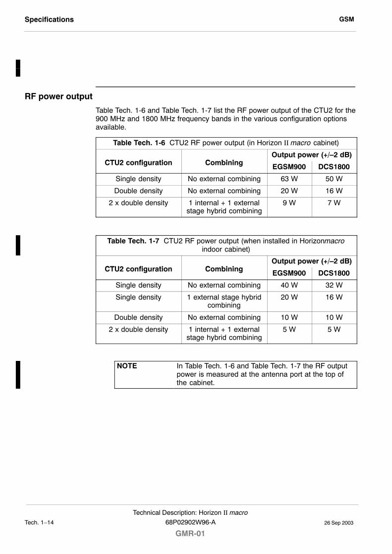
GSMSpecifications
26 Sep 2003Tech. 1�14
Technical Description: Horizon II macro
GMR-0168P02902W96-A
RF power output
Table Tech. 1-6 and Table Tech. 1-7 list the RF power output of the CTU2 for the900 MHz and 1800 MHz frequency bands in the various configuration optionsavailable.
Table Tech. 1-6 CTU2 RF power output (in Horizon II macro cabinet)
CTU2 co fig ratio Co bi i gOutput power (+/�2 dB)
CTU2 configuration Combining EGSM900 DCS1800
Single density No external combining 63 W 50 W
Double density No external combining 20 W 16 W
2 x double density 1 internal + 1 externalstage hybrid combining
9 W 7 W
Table Tech. 1-7 CTU2 RF power output (when installed in Horizonmacroindoor cabinet)
CTU2 co fig ratio Co bi i gOutput power (+/�2 dB)
CTU2 configuration Combining EGSM900 DCS1800
Single density No external combining 40 W 32 W
Single density 1 external stage hybridcombining
20 W 16 W
Double density No external combining 10 W 10 W
2 x double density 1 internal + 1 externalstage hybrid combining
5 W 5 W
NOTE In Table Tech. 1-6 and Table Tech. 1-7 the RF outputpower is measured at the antenna port at the top ofthe cabinet.
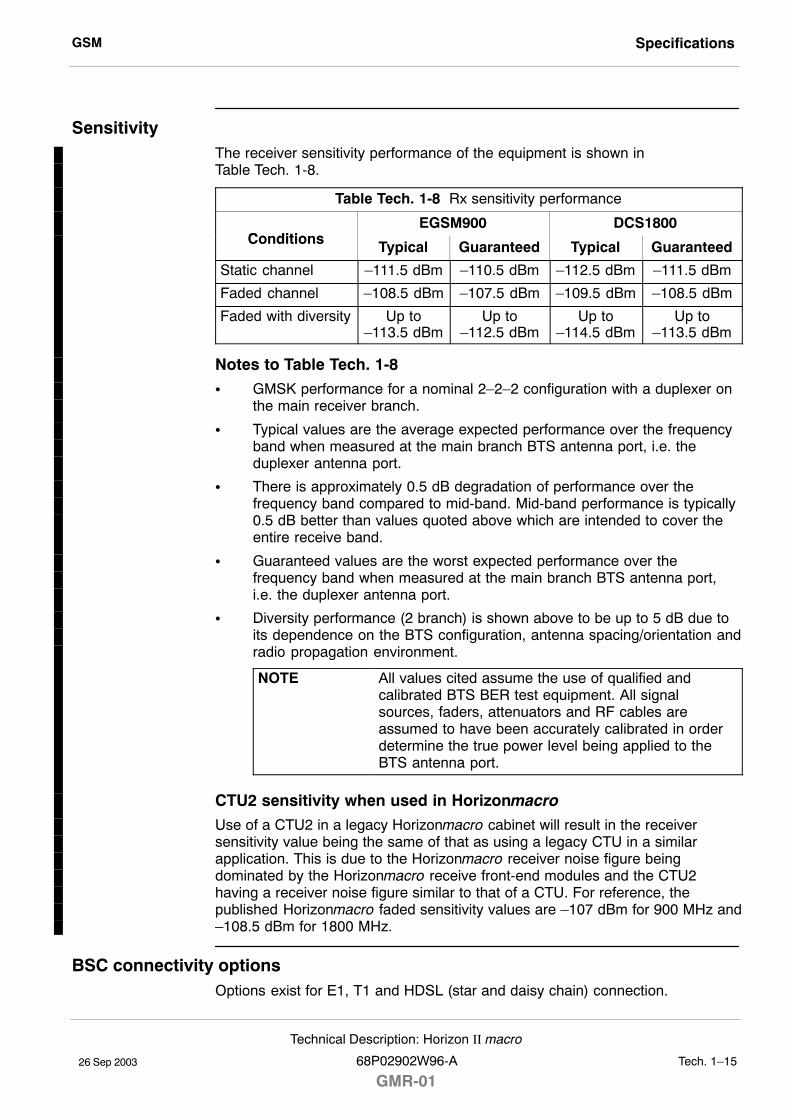
GSM Specifications
26 Sep 2003
Technical Description: Horizon II macro
68P02902W96-A
GMR-01Tech. 1�15
SensitivityThe receiver sensitivity performance of the equipment is shown inTable Tech. 1-8.
Table Tech. 1-8 Rx sensitivity performance
Co ditio sEGSM900 DCS1800
Conditions Typical Guaranteed Typical Guaranteed
Static channel �111.5 dBm �110.5 dBm �112.5 dBm �111.5 dBm
Faded channel �108.5 dBm �107.5 dBm �109.5 dBm �108.5 dBm
Faded with diversity Up to�113.5 dBm
Up to�112.5 dBm
Up to�114.5 dBm
Up to�113.5 dBm
Notes to Table Tech. 1-8
S GMSK performance for a nominal 2�2�2 configuration with a duplexer onthe main receiver branch.
S Typical values are the average expected performance over the frequencyband when measured at the main branch BTS antenna port, i.e. theduplexer antenna port.
S There is approximately 0.5 dB degradation of performance over thefrequency band compared to mid-band. Mid-band performance is typically0.5 dB better than values quoted above which are intended to cover theentire receive band.
S Guaranteed values are the worst expected performance over thefrequency band when measured at the main branch BTS antenna port,i.e. the duplexer antenna port.
S Diversity performance (2 branch) is shown above to be up to 5 dB due toits dependence on the BTS configuration, antenna spacing/orientation andradio propagation environment.
NOTE All values cited assume the use of qualified andcalibrated BTS BER test equipment. All signalsources, faders, attenuators and RF cables areassumed to have been accurately calibrated in orderdetermine the true power level being applied to theBTS antenna port.
CTU2 sensitivity when used in Horizonmacro
Use of a CTU2 in a legacy Horizonmacro cabinet will result in the receiversensitivity value being the same of that as using a legacy CTU in a similarapplication. This is due to the Horizonmacro receiver noise figure beingdominated by the Horizonmacro receive front-end modules and the CTU2having a receiver noise figure similar to that of a CTU. For reference, thepublished Horizonmacro faded sensitivity values are �107 dBm for 900 MHz and�108.5 dBm for 1800 MHz.
BSC connectivity optionsOptions exist for E1, T1 and HDSL (star and daisy chain) connection.
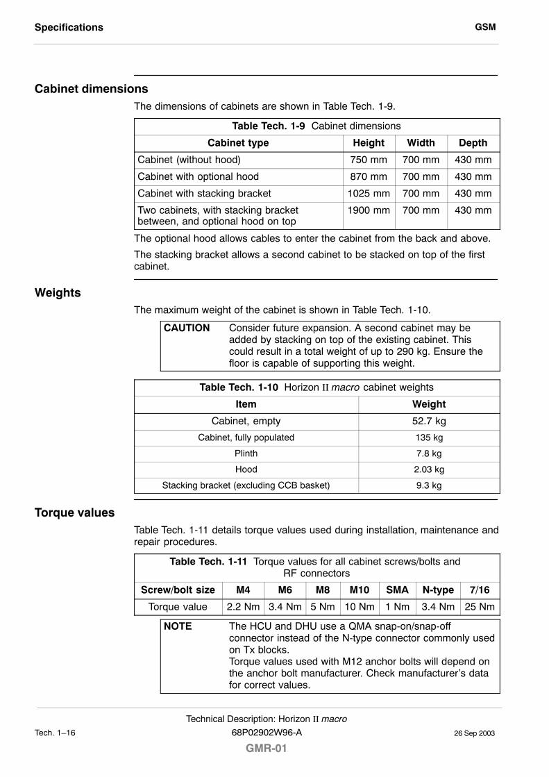
GSMSpecifications
26 Sep 2003Tech. 1�16
Technical Description: Horizon II macro
GMR-0168P02902W96-A
Cabinet dimensionsThe dimensions of cabinets are shown in Table Tech. 1-9.
Table Tech. 1-9 Cabinet dimensions
Cabinet type Height Width Depth
Cabinet (without hood) 750 mm 700 mm 430 mm
Cabinet with optional hood 870 mm 700 mm 430 mm
Cabinet with stacking bracket 1025 mm 700 mm 430 mm
Two cabinets, with stacking bracketbetween, and optional hood on top
1900 mm 700 mm 430 mm
The optional hood allows cables to enter the cabinet from the back and above.
The stacking bracket allows a second cabinet to be stacked on top of the firstcabinet.
WeightsThe maximum weight of the cabinet is shown in Table Tech. 1-10.
CAUTION Consider future expansion. A second cabinet may beadded by stacking on top of the existing cabinet. Thiscould result in a total weight of up to 290 kg. Ensure thefloor is capable of supporting this weight.
Table Tech. 1-10 Horizon II macro cabinet weights
Item Weight
Cabinet, empty 52.7 kg
Cabinet, fully populated 135 kg
Plinth 7.8 kg
Hood 2.03 kg
Stacking bracket (excluding CCB basket) 9.3 kg
Torque valuesTable Tech. 1-11 details torque values used during installation, maintenance andrepair procedures.
Table Tech. 1-11 Torque values for all cabinet screws/bolts and RF connectors
Screw/bolt size M4 M6 M8 M10 SMA N-type 7/16
Torque value 2.2 Nm 3.4 Nm 5 Nm 10 Nm 1 Nm 3.4 Nm 25 Nm
NOTE The HCU and DHU use a QMA snap-on/snap-offconnector instead of the N-type connector commonly usedon Tx blocks.Torque values used with M12 anchor bolts will depend onthe anchor bolt manufacturer. Check manufacturer�s datafor correct values.
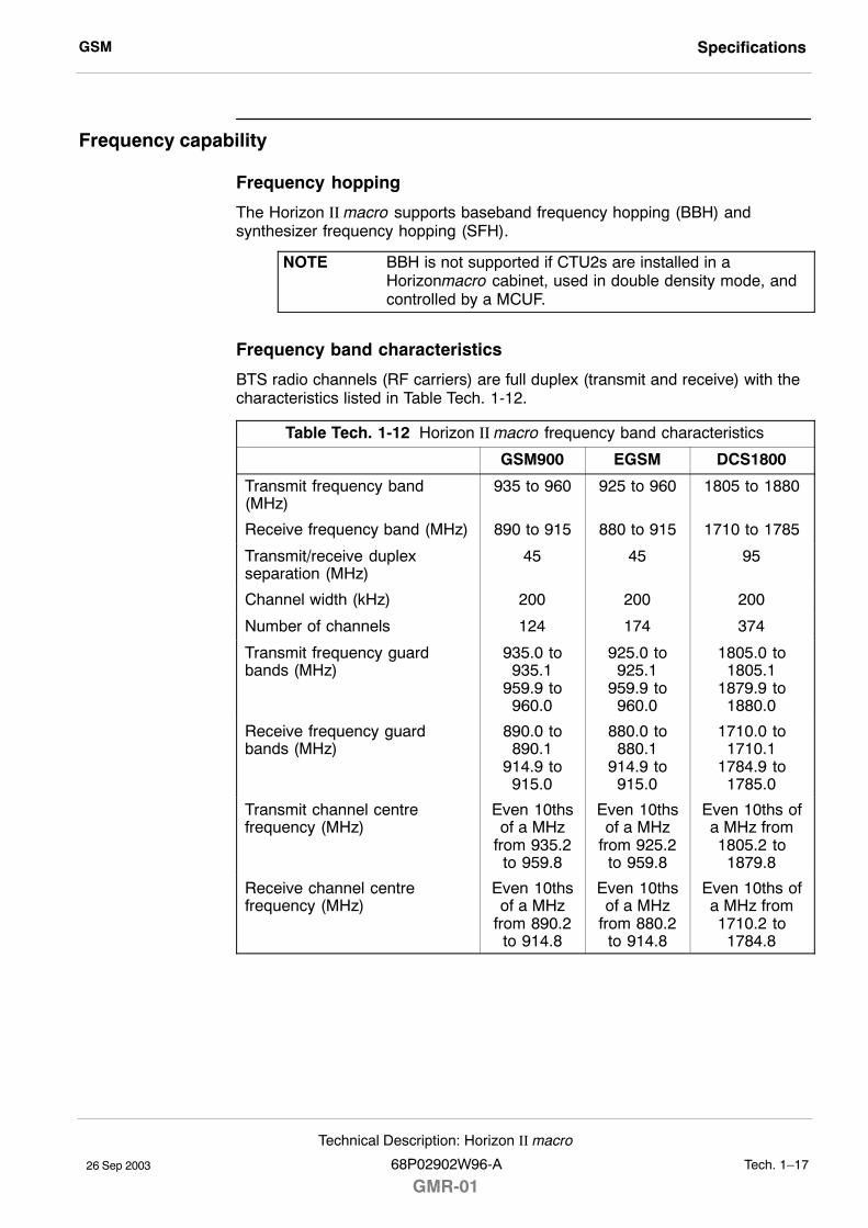
GSM Specifications
26 Sep 2003
Technical Description: Horizon II macro
68P02902W96-A
GMR-01Tech. 1�17
Frequency capability
Frequency hopping
The Horizon II macro supports baseband frequency hopping (BBH) andsynthesizer frequency hopping (SFH).
NOTE BBH is not supported if CTU2s are installed in aHorizonmacro cabinet, used in double density mode, andcontrolled by a MCUF.
Frequency band characteristics
BTS radio channels (RF carriers) are full duplex (transmit and receive) with thecharacteristics listed in Table Tech. 1-12.
Table Tech. 1-12 Horizon II macro frequency band characteristics
GSM900 EGSM DCS1800
Transmit frequency band(MHz)
935 to 960 925 to 960 1805 to 1880
Receive frequency band (MHz) 890 to 915 880 to 915 1710 to 1785
Transmit/receive duplexseparation (MHz)
45 45 95
Channel width (kHz) 200 200 200
Number of channels 124 174 374
Transmit frequency guardbands (MHz)
935.0 to935.1
959.9 to960.0
925.0 to925.1
959.9 to960.0
1805.0 to1805.1
1879.9 to1880.0
Receive frequency guardbands (MHz)
890.0 to890.1
914.9 to915.0
880.0 to880.1
914.9 to915.0
1710.0 to1710.1
1784.9 to1785.0
Transmit channel centrefrequency (MHz)
Even 10thsof a MHz
from 935.2to 959.8
Even 10thsof a MHz
from 925.2to 959.8
Even 10ths ofa MHz from1805.2 to
1879.8
Receive channel centrefrequency (MHz)
Even 10thsof a MHz
from 890.2to 914.8
Even 10thsof a MHz
from 880.2to 914.8
Even 10ths ofa MHz from1710.2 to
1784.8
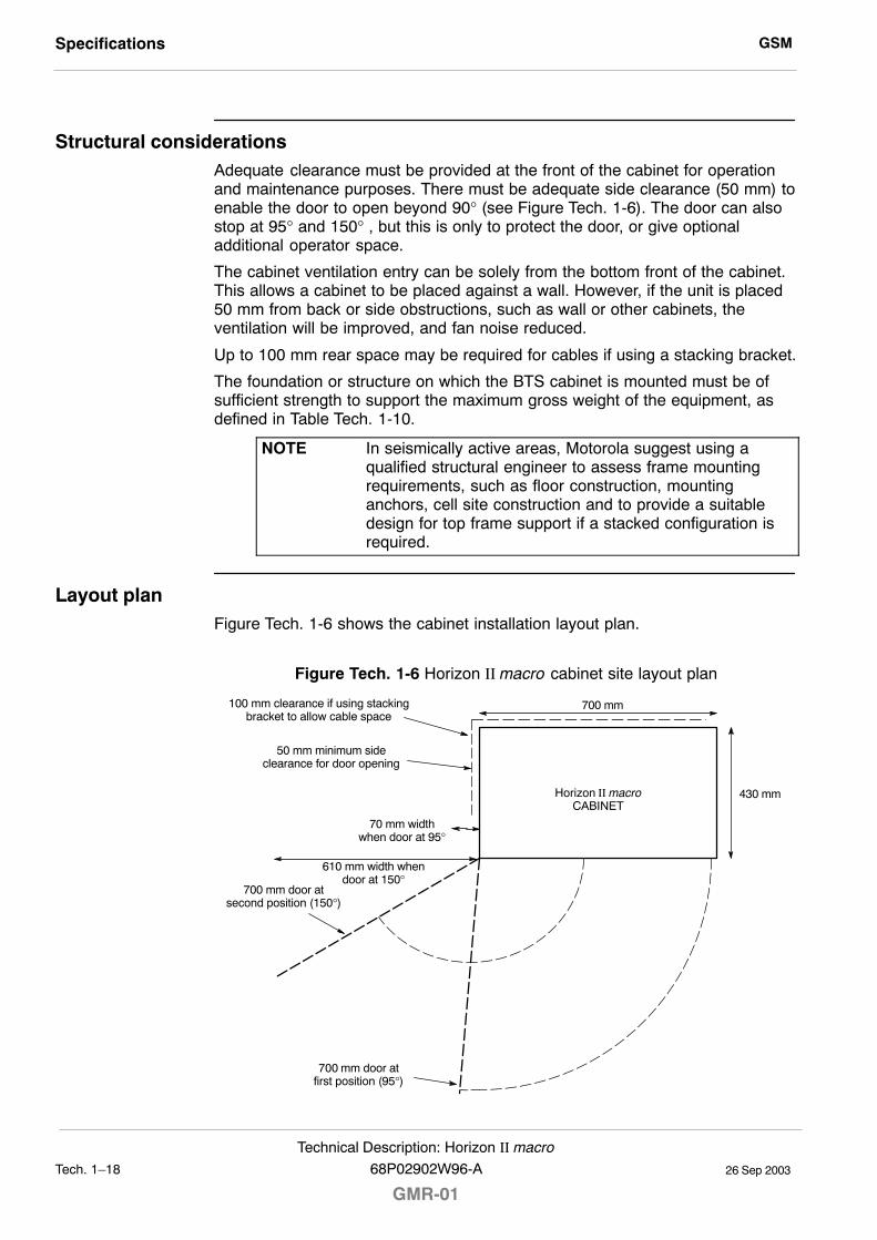
GSMSpecifications
26 Sep 2003Tech. 1�18
Technical Description: Horizon II macro
GMR-0168P02902W96-A
Structural considerationsAdequate clearance must be provided at the front of the cabinet for operationand maintenance purposes. There must be adequate side clearance (50 mm) toenable the door to open beyond 90° (see Figure Tech. 1-6). The door can alsostop at 95° and 150° , but this is only to protect the door, or give optionaladditional operator space.
The cabinet ventilation entry can be solely from the bottom front of the cabinet.This allows a cabinet to be placed against a wall. However, if the unit is placed50 mm from back or side obstructions, such as wall or other cabinets, theventilation will be improved, and fan noise reduced.
Up to 100 mm rear space may be required for cables if using a stacking bracket.
The foundation or structure on which the BTS cabinet is mounted must be ofsufficient strength to support the maximum gross weight of the equipment, asdefined in Table Tech. 1-10.
NOTE In seismically active areas, Motorola suggest using aqualified structural engineer to assess frame mountingrequirements, such as floor construction, mountinganchors, cell site construction and to provide a suitabledesign for top frame support if a stacked configuration isrequired.
Layout planFigure Tech. 1-6 shows the cabinet installation layout plan.
Figure Tech. 1-6 Horizon II macro cabinet site layout plan
700 mm door atfirst position (95°)
100 mm clearance if using stackingbracket to allow cable space
700 mm door atsecond position (150°)
430 mm
700 mm
Horizon II macroCABINET
50 mm minimum sideclearance for door opening
70 mm widthwhen door at 95°
610 mm width whendoor at 150°
26 Sep 2003
Technical Description: Horizon II macro
68P02902W96-A
GMR-01Tech. 2�1
Chapter 2
Cabinet structure

GSM
26 Sep 2003Tech. 2�2
Technical Description: Horizon II macro
GMR-0168P02902W96-A
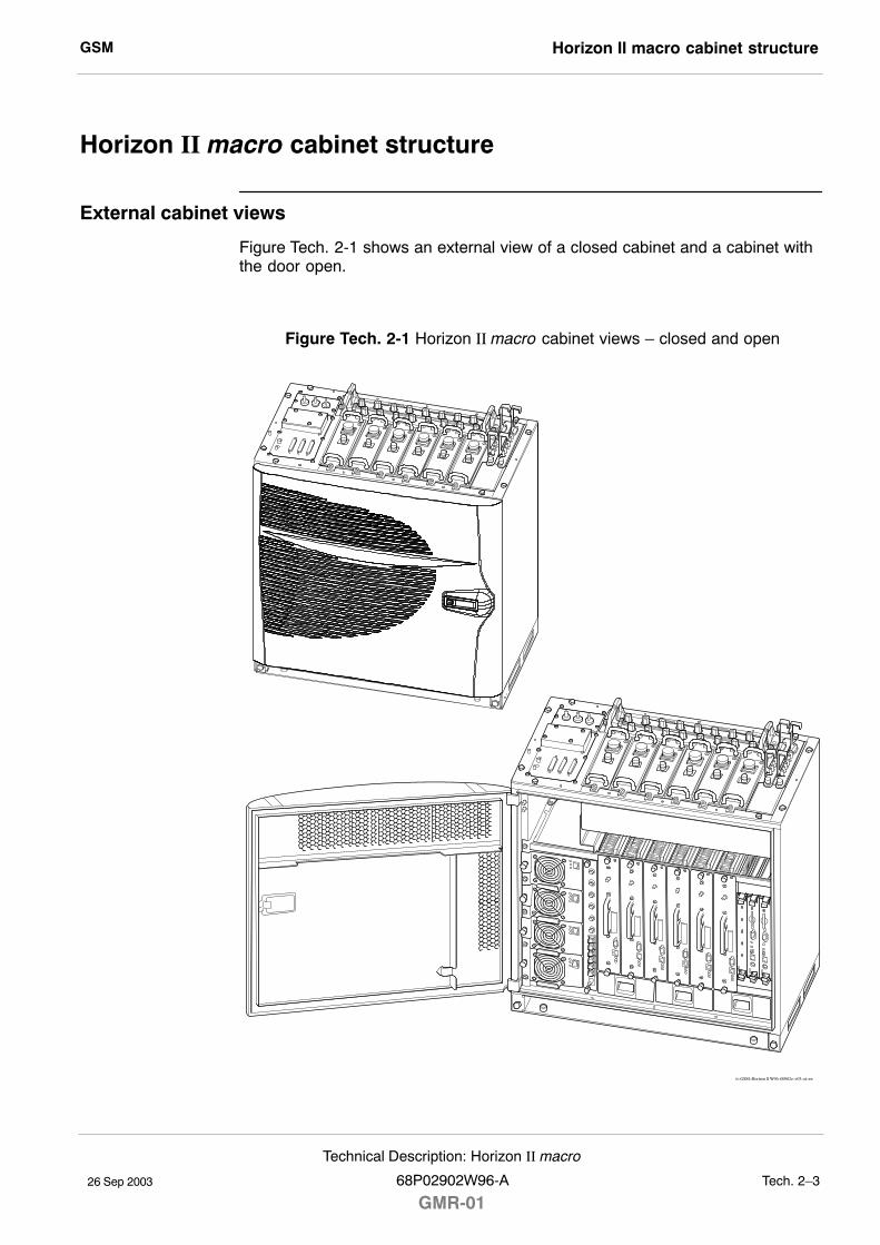
GSM Horizon II macro cabinet structure
26 Sep 2003
Technical Description: Horizon II macro
68P02902W96-A
GMR-01Tech. 2�3
Horizon II macro cabinet structure
External cabinet views
Figure Tech. 2-1 shows an external view of a closed cabinet and a cabinet withthe door open.
Figure Tech. 2-1 Horizon II macro cabinet views � closed and open
ti�GSM�Horizon ll W96�00002c�v03�ai�sw
GSMHorizon II macro cabinet structure
26 Sep 2003Tech. 2�4
Technical Description: Horizon II macro
GMR-0168P02902W96-A
Overview of structure description
The equipped cabinet is shown in Figure Tech. 2-2. The cabinet is designed forminimum maintenance and maximum ease of module replacement, and hasaccess only from the front and the top.
This chapter describes the cabinet structure and inner connections to assistunderstanding of the cabinet functions. There should be no need to dismantlethe cabinet beyond field replaceable unit (FRU) level.
The cabinet structure components are explained in the following sections:
Cabinet and SURF2 harness
This section describes the empty cabinet and the SURF2 harness connectionsbetween the SURF2 and the backplane and transceivers.
Top panel
This section describes the bare top panel with all the modules removed.
Cage backplane interface panel harness assembly (CBIA)
This section describes the CBIA. It also describes the backplane connectionsbetween all modules, and the harness from the backplane to the interface toppanel connectors.
Cabinet temperature control
This section describes the cabinet temperature control system.
Door and hood
This section describes the structure and function of the door and optional hood.
Stacking bracket
This section describes the optional stacking bracket, used for mounting asecond cabinet on top of the first.
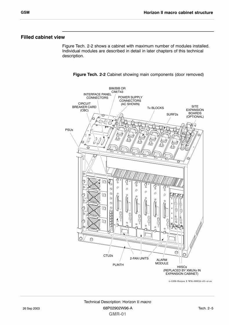
GSM Horizon II macro cabinet structure
26 Sep 2003
Technical Description: Horizon II macro
68P02902W96-A
GMR-01Tech. 2�5
Filled cabinet view
Figure Tech. 2-2 shows a cabinet with maximum number of modules installed.Individual modules are described in detail in later chapters of this technicaldescription.
Figure Tech. 2-2 Cabinet showing main components (door removed)
CIRCUITBREAKER CARD
(CBC)
HIISCs(REPLACED BY XMUXs IN
EXPANSION CABINET)
ALARMMODULE
2-FAN UNITSCTU2s
Tx BLOCKS
SURF2s
SITEEXPANSION
BOARDS(OPTIONAL)
PSUs
PLINTH
POWER SUPPLYCONNECTORS(AC SHOWN)
INTERFACE PANELCONNECTORS
BIM/BIB ORCIM/T43
ti�GSM�Horizon ll W96�00002d�v01�ai�sw
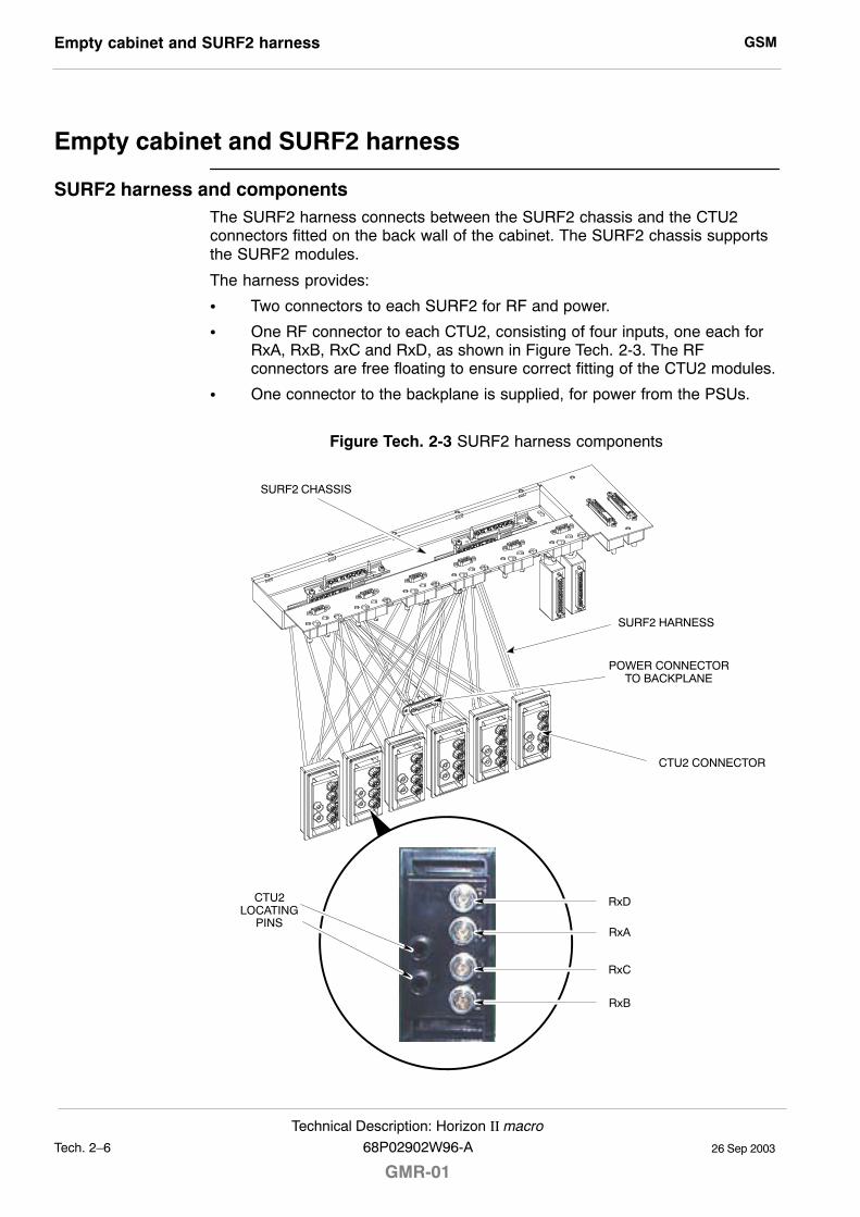
GSMEmpty cabinet and SURF2 harness
26 Sep 2003Tech. 2�6
Technical Description: Horizon II macro
GMR-0168P02902W96-A
Empty cabinet and SURF2 harness
SURF2 harness and componentsThe SURF2 harness connects between the SURF2 chassis and the CTU2connectors fitted on the back wall of the cabinet. The SURF2 chassis supportsthe SURF2 modules.
The harness provides:
S Two connectors to each SURF2 for RF and power.
S One RF connector to each CTU2, consisting of four inputs, one each forRxA, RxB, RxC and RxD, as shown in Figure Tech. 2-3. The RFconnectors are free floating to ensure correct fitting of the CTU2 modules.
S One connector to the backplane is supplied, for power from the PSUs.
Figure Tech. 2-3 SURF2 harness components
SURF2 CHASSIS
POWER CONNECTORTO BACKPLANE
CTU2 CONNECTOR
CTU2LOCATING
PINS
RxD
RxA
RxC
RxB
SURF2 HARNESS
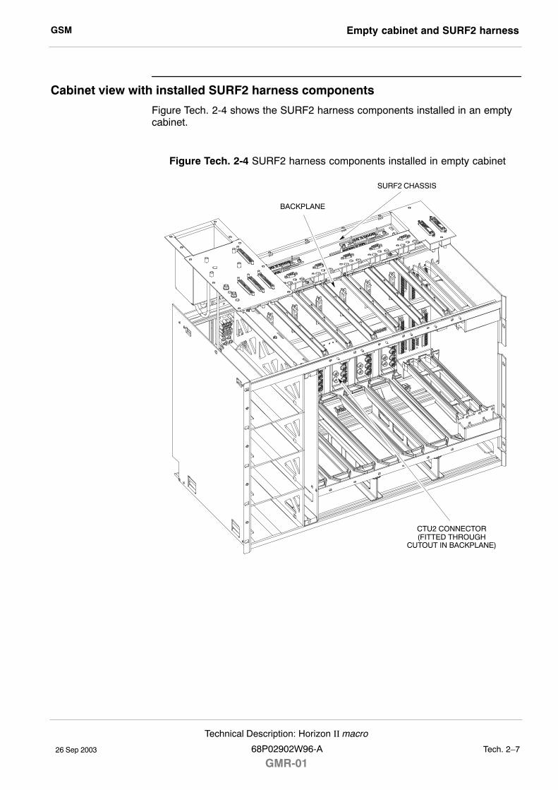
GSM Empty cabinet and SURF2 harness
26 Sep 2003
Technical Description: Horizon II macro
68P02902W96-A
GMR-01Tech. 2�7
Cabinet view with installed SURF2 harness components
Figure Tech. 2-4 shows the SURF2 harness components installed in an emptycabinet.
Figure Tech. 2-4 SURF2 harness components installed in empty cabinet
SURF2 CHASSIS
CTU2 CONNECTOR(FITTED THROUGH
CUTOUT IN BACKPLANE)
BACKPLANE
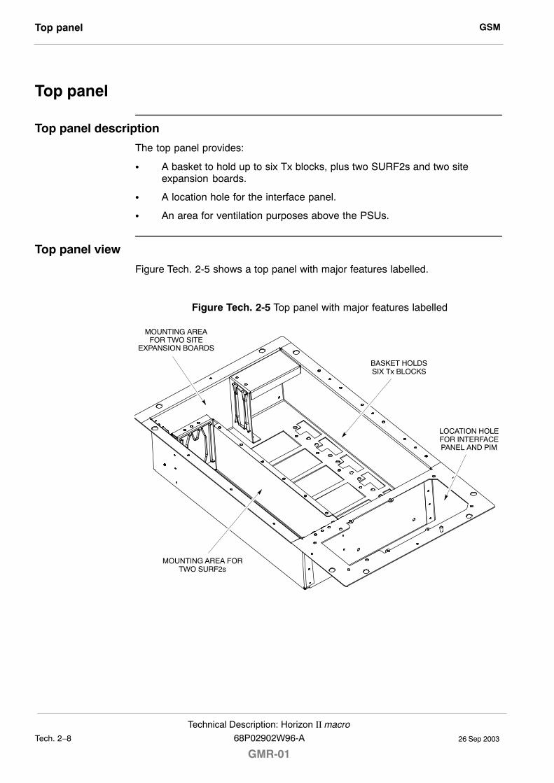
GSMTop panel
26 Sep 2003Tech. 2�8
Technical Description: Horizon II macro
GMR-0168P02902W96-A
Top panel
Top panel description
The top panel provides:
S A basket to hold up to six Tx blocks, plus two SURF2s and two siteexpansion boards.
S A location hole for the interface panel.
S An area for ventilation purposes above the PSUs.
Top panel view
Figure Tech. 2-5 shows a top panel with major features labelled.
Figure Tech. 2-5 Top panel with major features labelled
MOUNTING AREA FORTWO SURF2s
LOCATION HOLEFOR INTERFACEPANEL AND PIM
BASKET HOLDSSIX Tx BLOCKS
MOUNTING AREAFOR TWO SITE
EXPANSION BOARDS
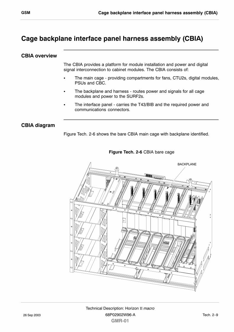
GSM Cage backplane interface panel harness assembly (CBIA)
26 Sep 2003
Technical Description: Horizon II macro
68P02902W96-A
GMR-01Tech. 2�9
Cage backplane interface panel harness assembly (CBIA)
CBIA overview
The CBIA provides a platform for module installation and power and digitalsignal interconnection to cabinet modules. The CBIA consists of:
S The main cage - providing compartments for fans, CTU2s, digital modules,PSUs and CBC.
S The backplane and harness - routes power and signals for all cagemodules and power to the SURF2s.
S The interface panel - carries the T43/BIB and the required power andcommunications connectors.
CBIA diagram
Figure Tech. 2-6 shows the bare CBIA main cage with backplane identified.
Figure Tech. 2-6 CBIA bare cage
BACKPLANE
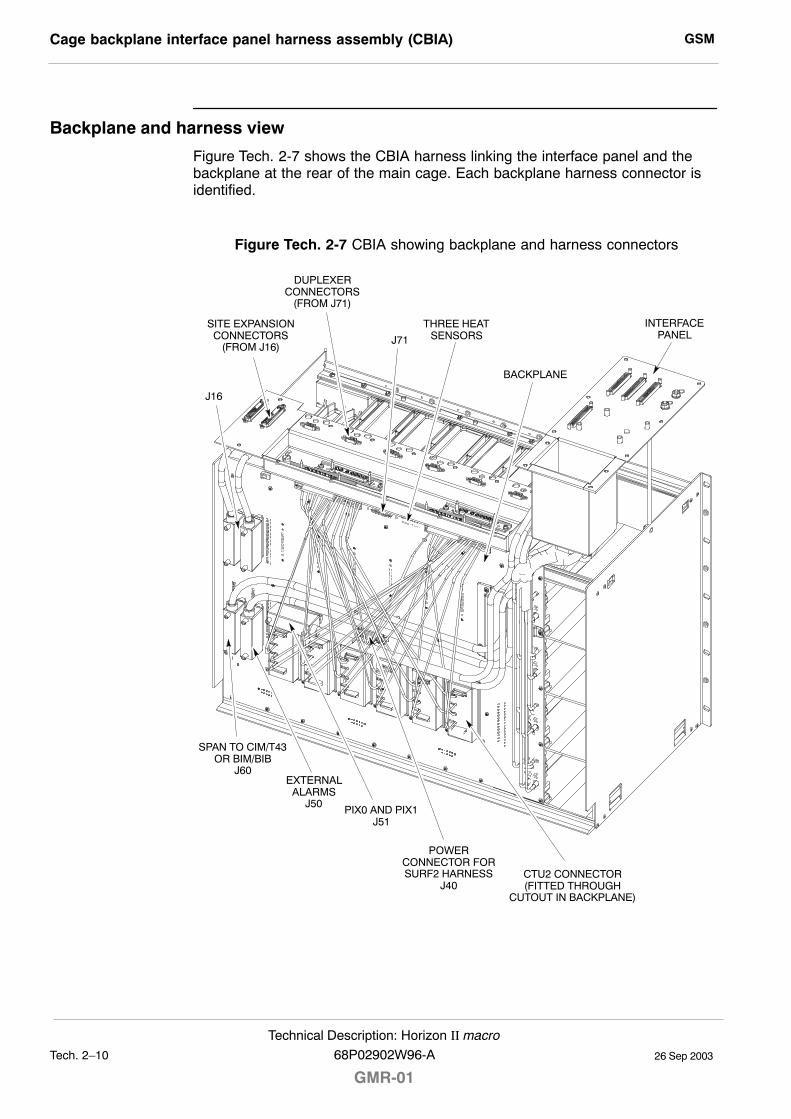
GSMCage backplane interface panel harness assembly (CBIA)
26 Sep 2003Tech. 2�10
Technical Description: Horizon II macro
GMR-0168P02902W96-A
Backplane and harness view
Figure Tech. 2-7 shows the CBIA harness linking the interface panel and thebackplane at the rear of the main cage. Each backplane harness connector isidentified.
Figure Tech. 2-7 CBIA showing backplane and harness connectors
THREE HEATSENSORS
CTU2 CONNECTOR(FITTED THROUGH
CUTOUT IN BACKPLANE)
POWERCONNECTOR FORSURF2 HARNESS
J40
INTERFACEPANEL
EXTERNALALARMS
J50
BACKPLANE
SITE EXPANSIONCONNECTORS
(FROM J16)
DUPLEXERCONNECTORS
(FROM J71)
J71
J16
SPAN TO CIM/T43OR BIM/BIB
J60
PIX0 AND PIX1J51
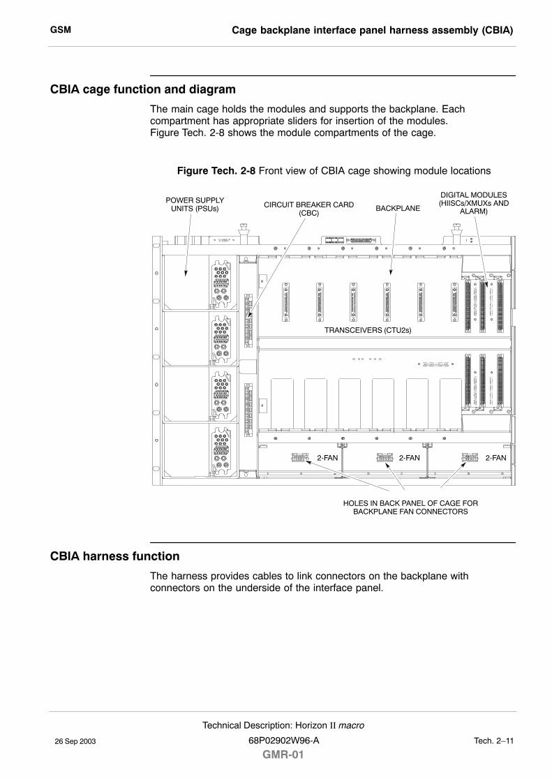
GSM Cage backplane interface panel harness assembly (CBIA)
26 Sep 2003
Technical Description: Horizon II macro
68P02902W96-A
GMR-01Tech. 2�11
CBIA cage function and diagram
The main cage holds the modules and supports the backplane. Eachcompartment has appropriate sliders for insertion of the modules.Figure Tech. 2-8 shows the module compartments of the cage.
Figure Tech. 2-8 Front view of CBIA cage showing module locations
TRANSCEIVERS (CTU2s)
HOLES IN BACK PANEL OF CAGE FORBACKPLANE FAN CONNECTORS
DIGITAL MODULES(HIISCs/XMUXs AND
ALARM)
2-FAN 2-FAN 2-FAN
CIRCUIT BREAKER CARD(CBC)
POWER SUPPLYUNITS (PSUs) BACKPLANE
CBIA harness function
The harness provides cables to link connectors on the backplane withconnectors on the underside of the interface panel.
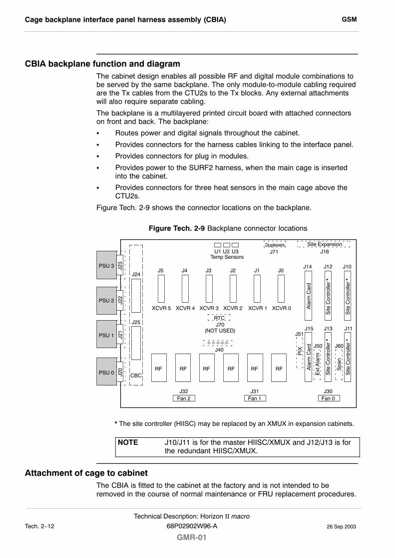
GSMCage backplane interface panel harness assembly (CBIA)
26 Sep 2003Tech. 2�12
Technical Description: Horizon II macro
GMR-0168P02902W96-A
CBIA backplane function and diagramThe cabinet design enables all possible RF and digital module combinations tobe served by the same backplane. The only module-to-module cabling requiredare the Tx cables from the CTU2s to the Tx blocks. Any external attachmentswill also require separate cabling.
The backplane is a multilayered printed circuit board with attached connectorson front and back. The backplane:
S Routes power and digital signals throughout the cabinet.
S Provides connectors for the harness cables linking to the interface panel.
S Provides connectors for plug in modules.
S Provides power to the SURF2 harness, when the main cage is insertedinto the cabinet.
S Provides connectors for three heat sensors in the main cage above theCTU2s.
Figure Tech. 2-9 shows the connector locations on the backplane.
Figure Tech. 2-9 Backplane connector locations
Site ExpansionDuplexers
J16J71U3U2U1Temp Sensors
J10J12J14J0J1J2J3J4J5
XCVR 0XCVR 1XCVR 2XCVR 3XCVR 4XCVR 5
RTCJ70
(NOT USED)
J40
RFRFRFRFRFRF
J24
J25
CBC
J23
J22
J21
J20
PSU 3
PSU 2
PSU 1
PSU 0
Fan 2 Fan 1 Fan 0J32 J31 J30
J15 J13 J11J51
J50 J60
PIX
Ala
rm C
ard
Ala
rm C
ard
Ext
Ala
rm
Spa
n
Site
Con
trol
ler
*S
ite C
ontr
olle
r *
Site
Con
trol
ler
*S
ite C
ontr
olle
r *
* The site controller (HIISC) may be replaced by an XMUX in expansion cabinets.
NOTE J10/J11 is for the master HIISC/XMUX and J12/J13 is forthe redundant HIISC/XMUX.
Attachment of cage to cabinetThe CBIA is fitted to the cabinet at the factory and is not intended to beremoved in the course of normal maintenance or FRU replacement procedures.
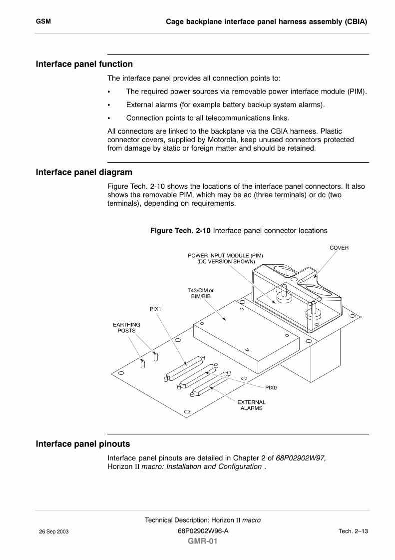
GSM Cage backplane interface panel harness assembly (CBIA)
26 Sep 2003
Technical Description: Horizon II macro
68P02902W96-A
GMR-01Tech. 2�13
Interface panel function
The interface panel provides all connection points to:
S The required power sources via removable power interface module (PIM).
S External alarms (for example battery backup system alarms).
S Connection points to all telecommunications links.
All connectors are linked to the backplane via the CBIA harness. Plasticconnector covers, supplied by Motorola, keep unused connectors protectedfrom damage by static or foreign matter and should be retained.
Interface panel diagram
Figure Tech. 2-10 shows the locations of the interface panel connectors. It alsoshows the removable PIM, which may be ac (three terminals) or dc (twoterminals), depending on requirements.
Figure Tech. 2-10 Interface panel connector locations
T43/CIM orBIM/BIB
POWER INPUT MODULE (PIM) (DC VERSION SHOWN)
EXTERNALALARMS
PIX1
PIX0
EARTHINGPOSTS
COVER
Interface panel pinouts
Interface panel pinouts are detailed in Chapter 2 of 68P02902W97,Horizon II macro: Installation and Configuration .
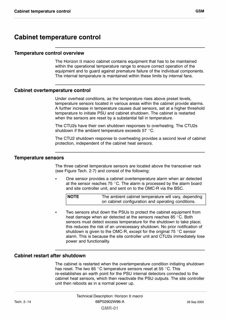
GSMCabinet temperature control
26 Sep 2003Tech. 2�14
Technical Description: Horizon II macro
GMR-0168P02902W96-A
Cabinet temperature control
Temperature control overview
The Horizon II macro cabinet contains equipment that has to be maintainedwithin the operational temperature range to ensure correct operation of theequipment and to guard against premature failure of the individual components.The internal temperature is maintained within these limits by internal fans.
Cabinet overtemperature control
Under overheat conditions, as the temperature rises above preset levels,temperature sensors located in various areas within the cabinet provide alarms.A further increase in temperature causes dual sensors, set at a higher thresholdtemperature to initiate PSU and cabinet shutdown. The cabinet is restartedwhen the sensors are reset by a substantial fall in temperature.
The CTU2s have their own shutdown responses to overheating. The CTU2sshutdown if the ambient temperature exceeds 57 _C.
The CTU2 shutdown response to overheating provides a second level of cabinetprotection, independent of the cabinet heat sensors.
Temperature sensors
The three cabinet temperature sensors are located above the transceiver rack(see Figure Tech. 2-7) and consist of the following:
S One sensor provides a cabinet overtemperature alarm when air detectedat the sensor reaches 75 _C. The alarm is processed by the alarm boardand site controller unit, and sent on to the OMC-R via the BSC.
NOTE The ambient cabinet temperature will vary, dependingon cabinet configuration and operating conditions.
S Two sensors shut down the PSUs to protect the cabinet equipment fromheat damage when air detected at the sensors reaches 85 _C. Bothsensors must detect excess temperature for the shutdown to take place;this reduces the risk of an unnecessary shutdown. No prior notification ofshutdown is given to the OMC-R, except for the original 75 _C sensoralarm. This is because the site controller unit and CTU2s immediately losepower and functionality.
Cabinet restart after shutdown
The cabinet is restarted when the overtemperature condition initiating shutdownhas reset. The two 85 _C temperature sensors reset at 55 _C. Thisre-establishes an earth point for the PSU internal detectors connected to thecabinet heat sensors, which then reactivate the PSU outputs. The site controllerunit then reboots as in a normal power up.
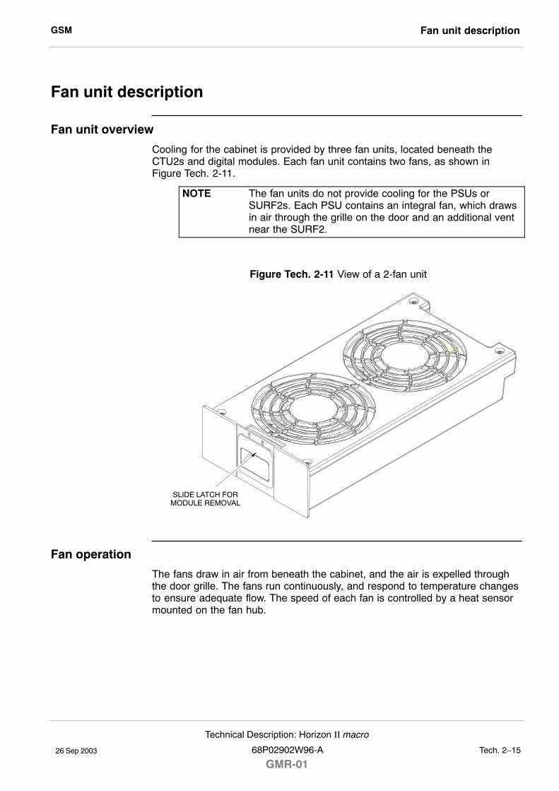
GSM Fan unit description
26 Sep 2003
Technical Description: Horizon II macro
68P02902W96-A
GMR-01Tech. 2�15
Fan unit description
Fan unit overview
Cooling for the cabinet is provided by three fan units, located beneath theCTU2s and digital modules. Each fan unit contains two fans, as shown inFigure Tech. 2-11.
NOTE The fan units do not provide cooling for the PSUs orSURF2s. Each PSU contains an integral fan, which drawsin air through the grille on the door and an additional ventnear the SURF2.
Figure Tech. 2-11 View of a 2-fan unit
SLIDE LATCH FORMODULE REMOVAL
Fan operation
The fans draw in air from beneath the cabinet, and the air is expelled throughthe door grille. The fans run continuously, and respond to temperature changesto ensure adequate flow. The speed of each fan is controlled by a heat sensormounted on the fan hub.
GSMCabinet door and optional hood
26 Sep 2003Tech. 2�16
Technical Description: Horizon II macro
GMR-0168P02902W96-A
Cabinet door and optional hood
Door functionThe cabinet is fitted with a door and may also be fitted with an optional hood.The hood cannot be fitted in conjuction with a stacking bracket.
The door has the following functions:
S Protects the modules from damage.
S Ensures the correct air ventilation.
S Provides EMC shielding.
The door has an external ventilation grille with internal honeycomb grille and avertical aluminium air baffle. The door hinges allow detent opening positions of95° and 150°.
The lock is a trigger latch, opened (if unlocked) by pressing the middle button.There is also a door alarm bracket, which presses against the cabinet dooralarm switch, mounted at the bottom of the CBC front panel.
Door external and internal viewFigure Tech. 2-12 shows both sides of the cabinet door.
Figure Tech. 2-12 External and internal view of cabinet door
VENTILATIONGRILLE
EXTERNAL VIEW
TRIGGERLATCH
INTERNAL VIEW
AIR BAFFLE
HONEYCOMBVENTILATION
GRILLE
DOOR ALARMBRACKET
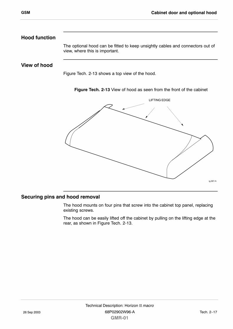
GSM Cabinet door and optional hood
26 Sep 2003
Technical Description: Horizon II macro
68P02902W96-A
GMR-01Tech. 2�17
Hood function
The optional hood can be fitted to keep unsightly cables and connectors out ofview, where this is important.
View of hood
Figure Tech. 2-13 shows a top view of the hood.
Figure Tech. 2-13 View of hood as seen from the front of the cabinet
LIFTING EDGE
ig.267.rh
Securing pins and hood removal
The hood mounts on four pins that screw into the cabinet top panel, replacingexisting screws.
The hood can be easily lifted off the cabinet by pulling on the lifting edge at therear, as shown in Figure Tech. 2-13.
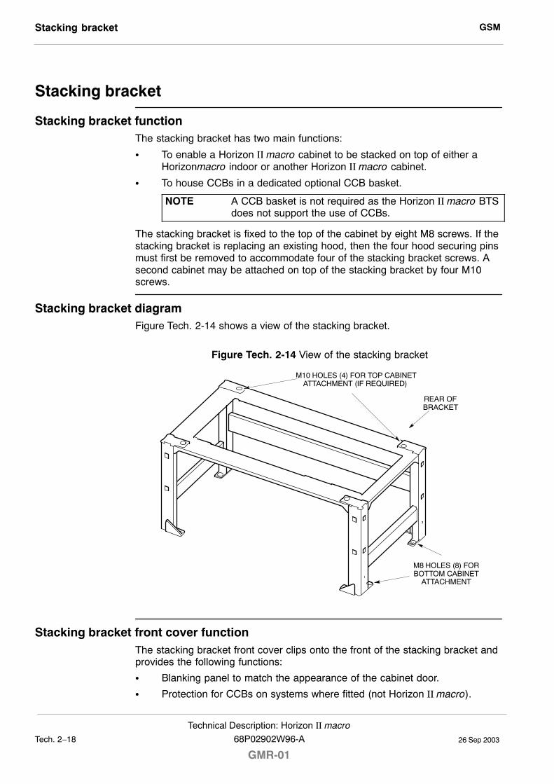
GSMStacking bracket
26 Sep 2003Tech. 2�18
Technical Description: Horizon II macro
GMR-0168P02902W96-A
Stacking bracket
Stacking bracket functionThe stacking bracket has two main functions:
S To enable a Horizon II macro cabinet to be stacked on top of either aHorizonmacro indoor or another Horizon II macro cabinet.
S To house CCBs in a dedicated optional CCB basket.
NOTE A CCB basket is not required as the Horizon II macro BTSdoes not support the use of CCBs.
The stacking bracket is fixed to the top of the cabinet by eight M8 screws. If thestacking bracket is replacing an existing hood, then the four hood securing pinsmust first be removed to accommodate four of the stacking bracket screws. Asecond cabinet may be attached on top of the stacking bracket by four M10screws.
Stacking bracket diagramFigure Tech. 2-14 shows a view of the stacking bracket.
Figure Tech. 2-14 View of the stacking bracket
M8 HOLES (8) FORBOTTOM CABINET
ATTACHMENT
M10 HOLES (4) FOR TOP CABINETATTACHMENT (IF REQUIRED)
REAR OFBRACKET
Stacking bracket front cover functionThe stacking bracket front cover clips onto the front of the stacking bracket andprovides the following functions:
S Blanking panel to match the appearance of the cabinet door.
S Protection for CCBs on systems where fitted (not Horizon II macro).
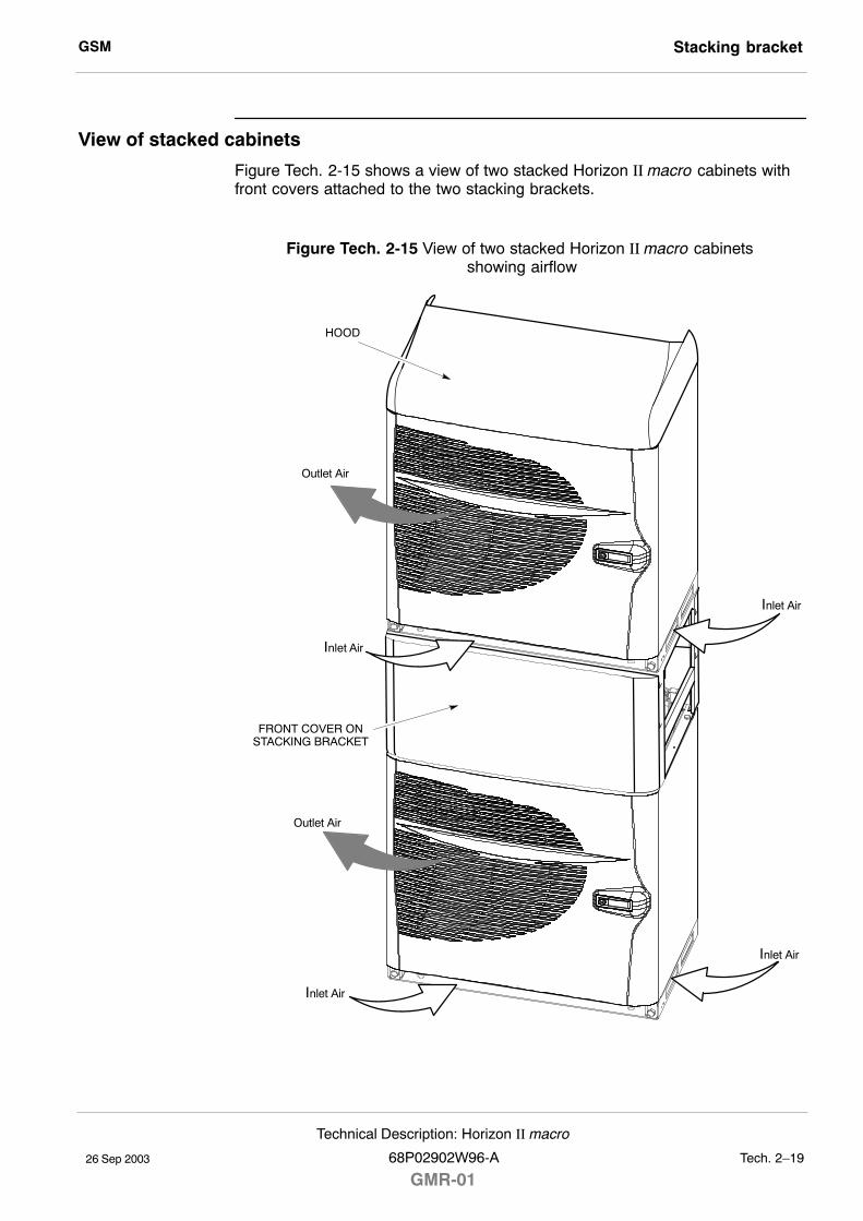
GSM Stacking bracket
26 Sep 2003
Technical Description: Horizon II macro
68P02902W96-A
GMR-01Tech. 2�19
View of stacked cabinets
Figure Tech. 2-15 shows a view of two stacked Horizon II macro cabinets withfront covers attached to the two stacking brackets.
Figure Tech. 2-15 View of two stacked Horizon II macro cabinets showing airflow
Inlet Air
FRONT COVER ONSTACKING BRACKET
Outlet Air
HOOD
Inlet Air
Outlet Air
Inlet Air
Inlet Air

GSMStacking bracket
26 Sep 2003Tech. 2�20
Technical Description: Horizon II macro
GMR-0168P02902W96-A

26 Sep 2003
Technical Description: Horizon II macro
68P02902W96-A
GMR-01Tech. 3�1
Chapter 3
Power distribution

GSM
26 Sep 2003Tech. 3�2
Technical Description: Horizon II macro
GMR-0168P02902W96-A
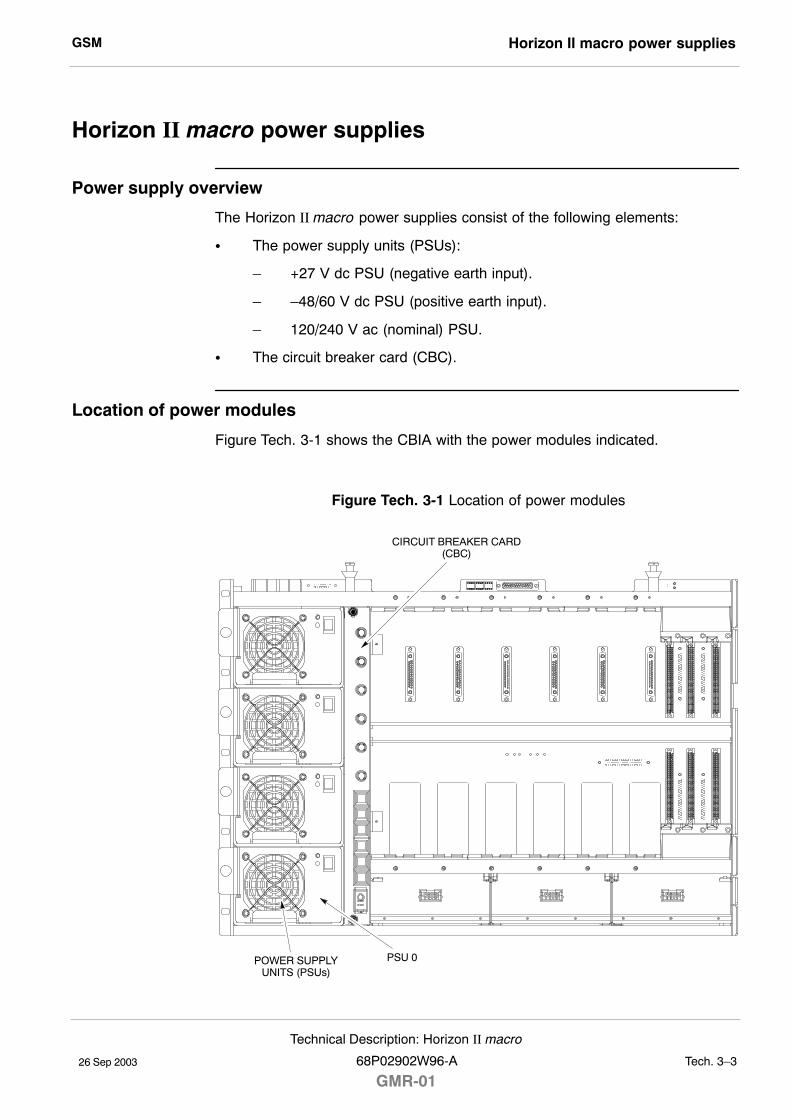
GSM Horizon II macro power supplies
26 Sep 2003
Technical Description: Horizon II macro
68P02902W96-A
GMR-01Tech. 3�3
Horizon II macro power supplies
Power supply overview
The Horizon II macro power supplies consist of the following elements:
S The power supply units (PSUs):
� +27 V dc PSU (negative earth input).
� �48/60 V dc PSU (positive earth input).
� 120/240 V ac (nominal) PSU.
S The circuit breaker card (CBC).
Location of power modules
Figure Tech. 3-1 shows the CBIA with the power modules indicated.
Figure Tech. 3-1 Location of power modules
CIRCUIT BREAKER CARD(CBC)
PSU 0POWER SUPPLYUNITS (PSUs)
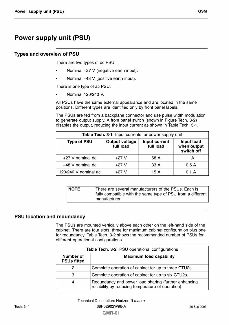
GSMPower supply unit (PSU)
26 Sep 2003Tech. 3�4
Technical Description: Horizon II macro
GMR-0168P02902W96-A
Power supply unit (PSU)
Types and overview of PSU
There are two types of dc PSU:
S Nominal +27 V (negative earth input).
S Nominal �48 V (positive earth input).
There is one type of ac PSU:
S Nominal 120/240 V.
All PSUs have the same external appearance and are located in the samepositions. Different types are identified only by front panel labels.
The PSUs are fed from a backplane connector and use pulse width modulationto generate output supply. A front panel switch (shown in Figure Tech. 3-2)disables the output, reducing the input current as shown in Table Tech. 3-1.
Table Tech. 3-1 Input currents for power supply unit
Type of PSU Output voltagefull load
Input currentfull load
Input loadwhen output
switch off
+27 V nominal dc +27 V 68 A 1 A
�48 V nominal dc +27 V 33 A 0.5 A
120/240 V nominal ac +27 V 15 A 0.1 A
NOTE There are several manufacturers of the PSUs. Each isfully compatible with the same type of PSU from a differentmanufacturer.
PSU location and redundancy
The PSUs are mounted vertically above each other on the left-hand side of thecabinet. There are four slots, three for maximum cabinet configuration plus onefor redundancy. Table Tech. 3-2 shows the recommended number of PSUs fordifferent operational configurations.
Table Tech. 3-2 PSU operational configurations
Number ofPSUs fitted
Maximum load capability
2 Complete operation of cabinet for up to three CTU2s.
3 Complete operation of cabinet for up to six CTU2s.
4 Redundancy and power load sharing (further enhancingreliability by reducing temperature of operation).

GSM Power supply unit (PSU)
26 Sep 2003
Technical Description: Horizon II macro
68P02902W96-A
GMR-01Tech. 3�5
PSU module view
Figure Tech. 3-2 shows a view of the PSU with LEDs identified.
Figure Tech. 3-2 View of Horizon II macro PSU
M4 MODULEATTACHMENT
SCREW
GREEN LED(ACTIVE)
OUTPUTDISABLE SWITCH
AIRVENT
RED LED(ALARM)
HANDLE
PSU alarms
There are five alarm conditions for each PSU:
S Output overvoltage.
S Output undervoltage.
S Input undervoltage.
S Overtemperature.
S Fan failure.
The likely cause of the alarm is indicated by a combination of the front panelLEDs (see Table Tech. 3-3).
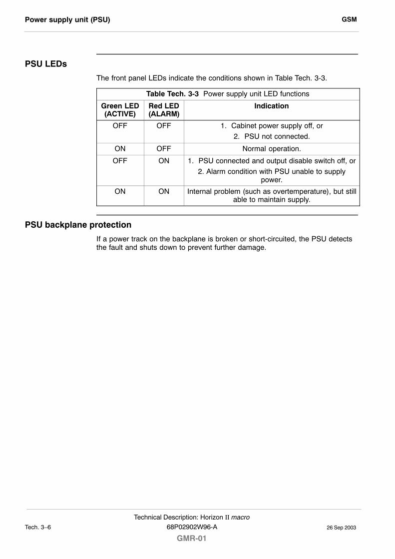
GSMPower supply unit (PSU)
26 Sep 2003Tech. 3�6
Technical Description: Horizon II macro
GMR-0168P02902W96-A
PSU LEDs
The front panel LEDs indicate the conditions shown in Table Tech. 3-3.
Table Tech. 3-3 Power supply unit LED functions
Green LED(ACTIVE)
Red LED(ALARM)
Indication
OFF OFF 1. Cabinet power supply off, or
2. PSU not connected.
ON OFF Normal operation.
OFF ON 1. PSU connected and output disable switch off, or
2. Alarm condition with PSU unable to supplypower.
ON ON Internal problem (such as overtemperature), but stillable to maintain supply.
PSU backplane protection
If a power track on the backplane is broken or short-circuited, the PSU detectsthe fault and shuts down to prevent further damage.
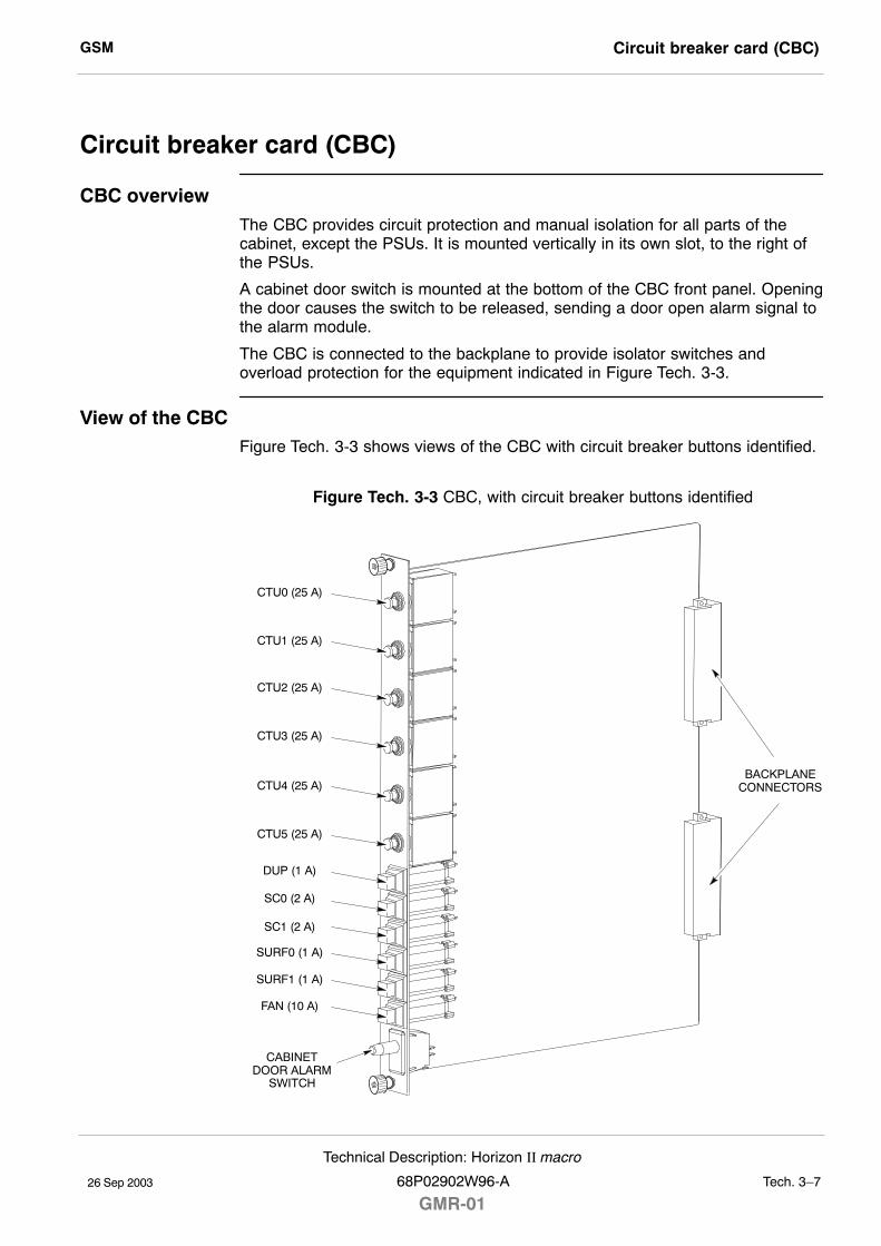
GSM Circuit breaker card (CBC)
26 Sep 2003
Technical Description: Horizon II macro
68P02902W96-A
GMR-01Tech. 3�7
Circuit breaker card (CBC)
CBC overviewThe CBC provides circuit protection and manual isolation for all parts of thecabinet, except the PSUs. It is mounted vertically in its own slot, to the right ofthe PSUs.
A cabinet door switch is mounted at the bottom of the CBC front panel. Openingthe door causes the switch to be released, sending a door open alarm signal tothe alarm module.
The CBC is connected to the backplane to provide isolator switches andoverload protection for the equipment indicated in Figure Tech. 3-3.
View of the CBCFigure Tech. 3-3 shows views of the CBC with circuit breaker buttons identified.
Figure Tech. 3-3 CBC, with circuit breaker buttons identified
BACKPLANECONNECTORS
CTU0 (25 A)
CTU1 (25 A)
CTU2 (25 A)
CTU3 (25 A)
CTU4 (25 A)
CTU5 (25 A)
SC0 (2 A)
SC1 (2 A)
SURF0 (1 A)
SURF1 (1 A)
DUP (1 A)
FAN (10 A)
CABINETDOOR ALARM
SWITCH
GSMCircuit breaker card (CBC)
26 Sep 2003Tech. 3�8
Technical Description: Horizon II macro
GMR-0168P02902W96-A
Operation of the CBC
Power for each protected module is supplied via the appropriate circuit breakerbutton. Overload of any circuit results in the appropriate circuit breaker buttontripping to the off (out) position. The button can be pressed to the on (in)position when the overload problem has been corrected.
Each protected module (identified in Figure Tech. 3-3) can be isolated bypressing and releasing the appropriate button to the off (out) position. Power isrestored by pushing the appropriate button to the on (in) position.
26 Sep 2003
Technical Description: Horizon II macro
68P02902W96-A
GMR-01Tech. 4�1
Chapter 4
RF modules

GSM
26 Sep 2003Tech. 4�2
Technical Description: Horizon II macro
GMR-0168P02902W96-A
GSM RF equipment description
26 Sep 2003
Technical Description: Horizon II macro
68P02902W96-A
GMR-01Tech. 4�3
RF equipment description
Overview of RF equipment
This chapter describes the functional operation of radio frequency (RF) modulesused in the Horizon II macro cabinet. All descriptions are presented at a blockdiagram level.
RF modules described
The following equipment is described:
S Compact transceiver unit (version 2) (CTU2). The CTU2 supports both theEGSM900 and DCS1800 frequency bands.
S Sectorized universal receiver front-end module (version 2) (SURF2). Twoversions of the SURF2 are available for the Horizon II macro: oneoperates in the 900 MHz frequency band and the other operates in the1800 MHz frequency band.
NOTE 900 MHz and 1800 MHz SURF2s cannot be installed inthe same cabinet. Similarly, CTU2s operating at 900 MHzand 1800 MHz cannot be mixed in the same cabinet.
S Several types of transmit block (Tx block). Tx blocks are used for variousconfigurations of transmit path, depending on number of antennas, CTU2sand functionality, including potential shared receive path.
RF general information and VSWR monitoring function
The following additional information is provided in this chapter:
S General definition of transmit and receive functions.
S An RF overview and VSWR monitoring function description.
S A brief explanation of CTU2 frequency hopping.
These descriptions are intended to assist the reader in understanding theinformation on the RF modules.
RF specifications
All equipment meets or exceeds ETSI regulations. Frequency information islisted in the Specifications section of Chapter 1.
GSMRF equipment description
26 Sep 2003Tech. 4�4
Technical Description: Horizon II macro
GMR-0168P02902W96-A
Receive (Rx) RF hardware
Receiver RF hardware consists of the SURF2 module and the receive section ofthe CTU2. The DUP is required for Rx filtering on the main (A) path and isoptional for the Rx diversity (B) path.
The SURF2 module provides bandpass filtering and low-noise amplification forup to three sectors, with two branch diversity receive antenna signals, togetherwith switching to CTU2s.
NOTE Four branch diversity is possible as a field upgrade withtwo SURF2s and an additional SURF2 harness installed inthe cabinet.
CTU2 Rx role
The CTU2 provides the following receive functions:
S Receiver tuning (on a timeslot basis) to any receive channel frequency.
S Demodulation and equalization of the receive channel signal.
S Measurement of the received signal strength indication (RSSI) and signalquality.
S Recovery of received data from the demodulated radio channel.
S Channel decoding of the received data and processing of the recoveredsignal. Traffic data is passed on to the site controller module for routeingto the MSC.
S Digital interface to the SURF2 module, which controls selection by theSURF2 switch of the receive signals from the appropriate antenna.
S Comparison and processing of an additional receive path from a seconddiversity antenna input to compensate for multipath fading andinterference.
Transmit (Tx) RF hardware
Transmit RF hardware consists of Tx blocks in appropriate combinations to meetrequirements of antenna sharing for the transceivers.
CTU2 Tx role
The CTU2 provides the following transmit functions:
S Transmit tuning (on a timeslot basis) for generation of any transmitchannel RF frequency.
S Encoding transmit data output.
S Digital modulation of transmit data onto the transmit radio channel signal.
S Final RF power amplification and output power level control of the transmitradio channel RF signal.
S Channel encoding of the data to be transmitted, interleaving signal andtraffic channel data, as defined by ETSI.
GSM RF equipment description
26 Sep 2003
Technical Description: Horizon II macro
68P02902W96-A
GMR-01Tech. 4�5
Rx/Tx single antenna duplexing
Duplexers allow a single antenna to be used for both transmit and receiveoperations. Normally duplexed RF signals pass through one antenna, with asecond receive antenna to provide diversity.
CAUTION If a single antenna (non-diversity) is required, the duplexantenna RF receive cable from the transmit block must beconnected to the RxA path at the SURF2. Simplyswitching off diversity at the OMC-R without the correctSURF2 configuration will cause a loss of reception.
GSMRF overview and antenna VSWR monitoring function
26 Sep 2003Tech. 4�6
Technical Description: Horizon II macro
GMR-0168P02902W96-A
RF overview and antenna VSWR monitoring function
RF overview
This section explains the RF functional blocks and additional antenna VSWRmonitoring function.
The terminology, functionality, and optional capabilities, are set out as a basisfor understanding more detailed descriptions in the RF module sections of thischapter.
RF main components
The following description should be read in conjunction with Figure Tech. 4-1.
The RF equipment consists of three main blocks:
S The CTU2.
S The SURF2.
S The Tx block.
CTU2
The CTU2 can operate at 900 MHz and 1800 MHz (dual carrier). It can receivetwo (single density or EDGE) or four (double density) Rx inputs from the SURF2.These inputs are converted into digital voice/data. The Rx signals providediversity of the Rx function from the MS (uplink).
The CTU2 generates a Tx data signal, translated from received digitalvoice/data, which is transmitted by cable to the Tx block for transmission via theantenna to the MS (downlink).
SURF2 module
Two types of SURF2 module are available for use in the Horizon II macro. Oneprovides 900 MHz reception capability and the other provides 1800 MHzreception capability.
Each SURF2 module accepts up to three pairs of antenna inputs. The SURF2switches the inputs to the appropriate CTU2s under the control of the databasevia the HIISC. There are two inputs to each CTU2 for Rx diversity.
The SURF2 does not contain any loopback test circuitry.
Tx block
Up to six Tx blocks can be installed in the Horizon II macro cabinet.
Tx blocks filter the transmit signal for the required Tx band. They also use filtersto enable the Rx frequency signal to be passed to the SURF2, if one antenna isused for both Tx and Rx signals.
GSM RF overview and antenna VSWR monitoring function
26 Sep 2003
Technical Description: Horizon II macro
68P02902W96-A
GMR-01Tech. 4�7
Antenna VSWR monitoring
Purpose
The antenna VSWR monitoring function is used to detect faults in antennas orantenna path connections. This is achieved by sending a known signal powerlevel to the antenna and then measuring the reflected power.
Hardware
The test signal for antenna VSWR monitoring is generated by the CTU2. TheDUP contains a VSWR monitoring circuit that monitors the reflected power. Ifthe return loss from the antenna port is less than 6 dB, a VSWR alarm signal issent to the alarm module.
RF loopback
Purpose
The loopback test function is primarily used to identify faults within the RFsystem. The loopback test function provides a diagnostic capability at theOMC-R, by creating a test signal to identify if the fault is either:
S Software (that the OMC-R can correct).
S Hardware (requires a site visit).
The result is a reduction in site assessment visits, and avoidance ofunnecessary visits when hardware is functioning correctly.
Hardware
The RF loopback test function is essentially a hardware capability built into theCTU2. Software instructions activate the test hardware, causing a loopbacksignal to be injected internally into the Rx input of the CTU2 to test its receivesection.
Software operation
The loopback test function is normally carried out under the control of theOMC-R.
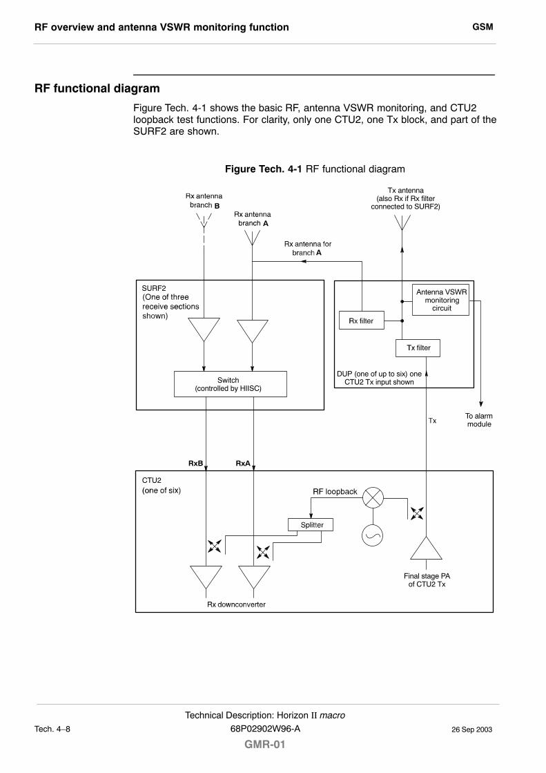
GSMRF overview and antenna VSWR monitoring function
26 Sep 2003Tech. 4�8
Technical Description: Horizon II macro
GMR-0168P02902W96-A
RF functional diagram
Figure Tech. 4-1 shows the basic RF, antenna VSWR monitoring, and CTU2loopback test functions. For clarity, only one CTU2, one Tx block, and part of theSURF2 are shown.
Figure Tech. 4-1 RF functional diagram
RxARxB
B
A
A
SURF2
Tx antenna(also Rx if Rx filter
connected to SURF2)
DUP (one of up to six) oneCTU2 Tx input shownSwitch
(controlled by HIISC)
CTU2
Final stage PAof CTU2 Tx
Antenna VSWRmonitoring
circuit
To alarmmodule
GSM Compact transceiver unit (CTU2)
26 Sep 2003
Technical Description: Horizon II macro
68P02902W96-A
GMR-01Tech. 4�9
Compact transceiver unit (CTU2)
Overview of the CTU2This section provides the technical description of the CTU2.
NOTE Two versions of the CTU2 are available for theHorizon II macro. One version operates in the EGSM900frequency band and the other operates in the DCS1800frequency band.
The CTU2:
S Generates the RF frequencies required to perform the transmit andreceive functions.
S Contains the digital circuits required for 32 timeslots of channelequalization, encoding and decoding, and transceiver control logic.
The CTU2 provides the air interface between a BSS and MSs, with the followingfeatures:
S Capability of diversity reception (input from up to four antennas) whichimproves the quality reception in the presence of multipath fading andinterference.
S Frequency change on a timeslot basis for frequency hopping andequipment sharing.
S Transmit power control.
CTU2 featuresThe CTU2 has the following features:
S Single or double density mode in a Horizon II macro cabinet. Singledensity mode provides single carrier GSM Tx capability. Double densitymode provides 2 carrier GSM Tx capability (both carriers must be in thesame sector).
S Single carrier EDGE Tx capability.
S Backwards compatible with CTU used in Horizonmacro indoor (withrestrictions).
S Transmit diversity.
S Two or four branch Rx diversity. (Four branch diversity requires 2 x SURF2modules and a second SURF2 harness cable to be installed.)
S Hardware support for AMR (upgrade required for pre-GSR7 software).
CTU2 Tx RF output specificationFor Tx RF output refer to Specifications in Chapter 1.
Location and requirementsThe CTU2 shelf is located below the basket for the Tx blocks, and takes up themajority of the space in the cabinet.
The cabinet can contain up to six CTU2s. At least one CTU2 must be fitted ineach cabinet. All CTU2s in the cabinet must operate at the same frequency(either 900 MHz or 1800 MHz).
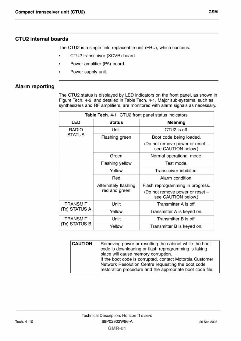
GSMCompact transceiver unit (CTU2)
26 Sep 2003Tech. 4�10
Technical Description: Horizon II macro
GMR-0168P02902W96-A
CTU2 internal boards
The CTU2 is a single field replaceable unit (FRU), which contains:
S CTU2 transceiver (XCVR) board.
S Power amplifier (PA) board.
S Power supply unit.
Alarm reporting
The CTU2 status is displayed by LED indicators on the front panel, as shown inFigure Tech. 4-2, and detailed in Table Tech. 4-1. Major sub-systems, such assynthesizers and RF amplifiers, are monitored with alarm signals as necessary.
Table Tech. 4-1 CTU2 front panel status indicators
LED Status Meaning
RADIOSTATUS
Unlit CTU2 is off.STATUS Flashing green Boot code being loaded.
(Do not remove power or reset �see CAUTION below.)
Green Normal operational mode.
Flashing yellow Test mode.
Yellow Transceiver inhibited.
Red Alarm condition.
Alternately flashingred and green
Flash reprogramming in progress.
(Do not remove power or reset �see CAUTION below.)
TRANSMIT(T ) STATUS A
Unlit Transmitter A is off.(Tx) STATUS A Yellow Transmitter A is keyed on.
TRANSMIT(T ) STATUS B
Unlit Transmitter B is off.(Tx) STATUS B Yellow Transmitter B is keyed on.
CAUTION Removing power or resetting the cabinet while the bootcode is downloading or flash reprogramming is takingplace will cause memory corruption.If the boot code is corrupted, contact Motorola CustomerNetwork Resolution Centre requesting the boot coderestoration procedure and the appropriate boot code file.
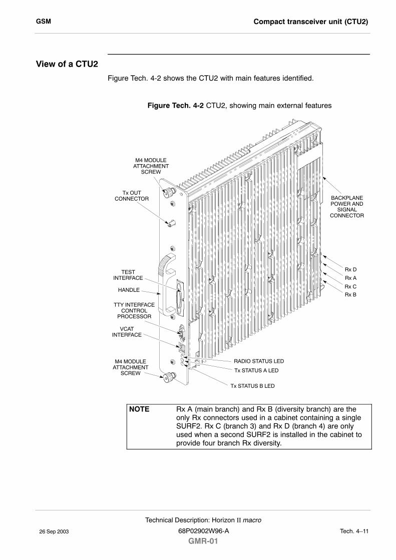
GSM Compact transceiver unit (CTU2)
26 Sep 2003
Technical Description: Horizon II macro
68P02902W96-A
GMR-01Tech. 4�11
View of a CTU2
Figure Tech. 4-2 shows the CTU2 with main features identified.
Figure Tech. 4-2 CTU2, showing main external features
Tx OUTCONNECTOR
Tx STATUS A LED
HANDLE
M4 MODULEATTACHMENT
SCREW
M4 MODULEATTACHMENT
SCREW
TTY INTERFACECONTROL
PROCESSOR
TESTINTERFACE
RADIO STATUS LED
Rx D
Rx A
BACKPLANEPOWER AND
SIGNALCONNECTOR
Rx C
Rx B
Tx STATUS B LED
VCATINTERFACE
NOTE Rx A (main branch) and Rx B (diversity branch) are theonly Rx connectors used in a cabinet containing a singleSURF2. Rx C (branch 3) and Rx D (branch 4) are onlyused when a second SURF2 is installed in the cabinet toprovide four branch Rx diversity.
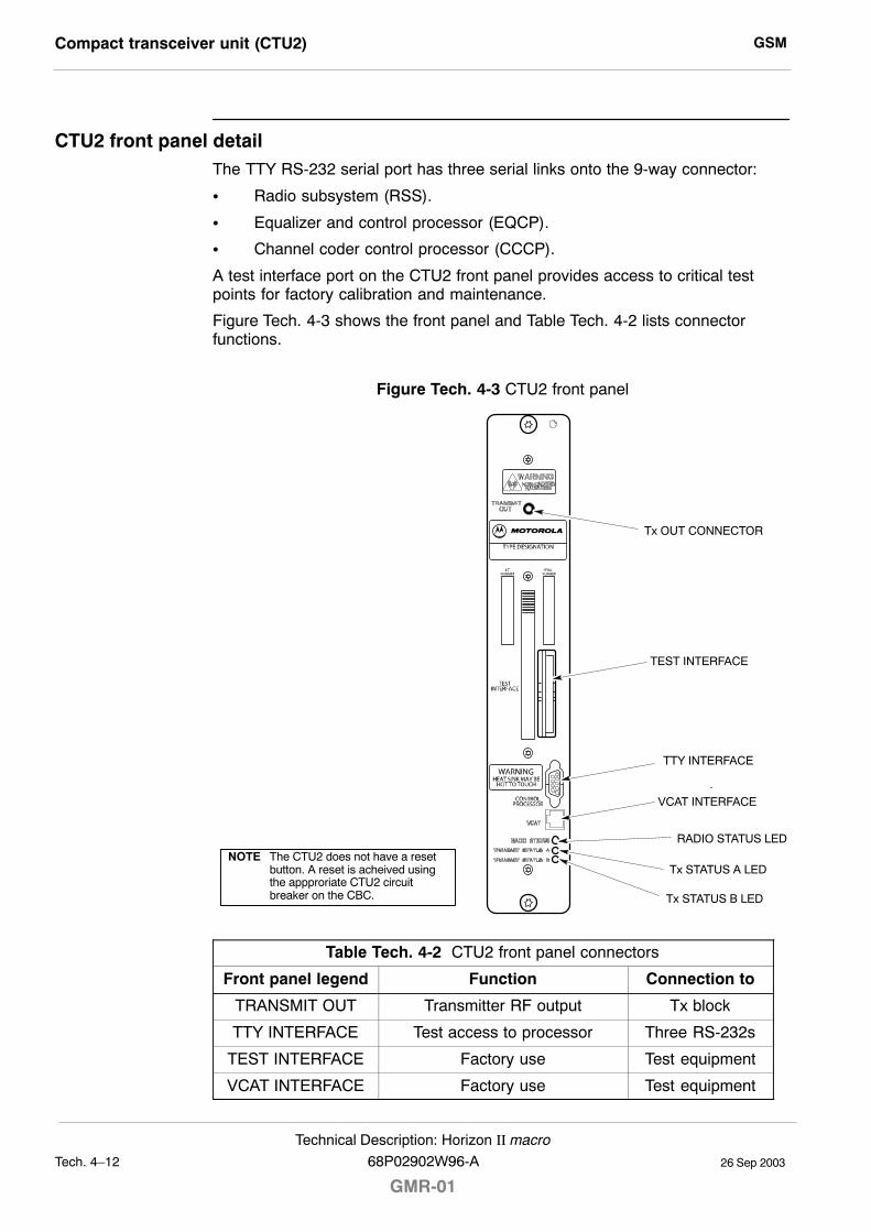
GSMCompact transceiver unit (CTU2)
26 Sep 2003Tech. 4�12
Technical Description: Horizon II macro
GMR-0168P02902W96-A
CTU2 front panel detailThe TTY RS-232 serial port has three serial links onto the 9-way connector:
S Radio subsystem (RSS).
S Equalizer and control processor (EQCP).
S Channel coder control processor (CCCP).
A test interface port on the CTU2 front panel provides access to critical testpoints for factory calibration and maintenance.
Figure Tech. 4-3 shows the front panel and Table Tech. 4-2 lists connectorfunctions.
Figure Tech. 4-3 CTU2 front panel
Tx OUT CONNECTOR
TTY INTERFACE
TEST INTERFACE
Tx STATUS B LED
RADIO STATUS LED
.
Tx STATUS A LED
VCAT INTERFACE
NOTE The CTU2 does not have a resetbutton. A reset is acheived usingthe appproriate CTU2 circuitbreaker on the CBC.
Table Tech. 4-2 CTU2 front panel connectors
Front panel legend Function Connection to
TRANSMIT OUT Transmitter RF output Tx block
TTY INTERFACE Test access to processor Three RS-232s
TEST INTERFACE Factory use Test equipment
VCAT INTERFACE Factory use Test equipment
GSM Compact transceiver unit (CTU2)
26 Sep 2003
Technical Description: Horizon II macro
68P02902W96-A
GMR-01Tech. 4�13
CTU2 Tx connector
The CTU2 Tx connector is a short SMA to SMA link to the base of theappropriate Tx block or feedthrough plate.
NOTE The Tx cable has a 90° SMA connector at one end and astraight SMA connector at the other end. The 90° end isdesigned for connection to the Tx port of the CTU2.
CTU2 Rx function
The receiver part of the CTU2 can accept two amplified and filtered receiveantenna signals from each SURF2 module (four Rx signals in total). These twosignals are applied to inputs (branch A and branch B) of the CTU2 transceiverboard.
The transceiver can be configured to provide double density receive capacity or4 branch Rx diversity. In double density mode, the receiver providesdemodulation of a main and diversity path for two RF channels. In 4 branch Rxdiversity mode, the receiver provides four independent Rx paths for one RFchannel.
The input from the SURF2 module is filtered, amplified and down converted toensure the signal level and frequency range are correct for the next stage.
CTU2 interface function
The CTU2 interface function provides the air interface timing and transceivercontrol circuitry required for Rx (uplink) and Tx (downlink) control functions.
The CTU2 interface includes:
S Master GSM air interface timing function.
S Independent Rx gain control interface for each diversity receiver branch.
S Baseband Rx data interface for each diversity receiver branch.
S Receiver front end control.
S Tx data interface including GMSK modulator which provides basebanddata to the transmitter.
S Tx and power amplifier power control interface.
S Rx and Tx frequency synthesizer control which supports RF frequencyhopping.
S CTU2 and cabinet alarm data collection.
S Alarms sampling and multiplexing.
GSMCTU2 frequency hopping
26 Sep 2003Tech. 4�14
Technical Description: Horizon II macro
GMR-0168P02902W96-A
CTU2 frequency hopping
Overview of CTU2 frequency hopping
The CTU2 supports two types of frequency hopping, synthesizer frequencyhopping (SFH) and baseband frequency hopping (BBH). This section providesan explanation of both types. In either type, the MS switches channels afterevery transmit/receive (Tx/Rx) burst pair. The difference between SFH and BBHis in the method by which channel switching is achieved at the BTS.
NOTE BBH is not possible if the CTU2 is used in double densitymode in a Horizonmacro cabinet which is controlled by aMCUF site controller (refer to System Information: BSSEquipment Planning (68P02900W21) for further details).
Synthesizer frequency hopping (SFH)
SFH can only be used with wideband combining.
A minimum of two CTU2s are required per cell due to BCCH requirements.Timeslot 0 of CTU2 0 is used for the BCCH carrier and therefore CTU2 0 cannotuse SFH. Only CTU2 1 and additional CTU2s can use SFH.
Baseband frequency hopping (BBH)
BBH can use either Tx blocks or CCB Tx combining equipment (not available forHorizon II macro). The main reason for using BBH instead of SFH is to enablefrequency hopping when using CCBs, because the mechanical tuning of CCBsis too slow for SFH.
The number of CTU2s required to support BBH is equal to the number offrequencies used.
GSM SURF2 module
26 Sep 2003
Technical Description: Horizon II macro
68P02902W96-A
GMR-01Tech. 4�15
SURF2 module
SURF2 module overview
The sectorized universal receiver front end (SURF2) module performs low noiseamplification, RF bandpass filtering, and antenna to CTU2 routeing through aswitch/splitter matrix. One SURF2 can route any of three Rx antenna inputs toany of six different CTU2s for both a main and diversity path. The SURF2 alsoprovides an expansion path from the antenna 0 input for both main and diversitypaths.
The SURF2 is single band and two versions are available for use in theHorizon II macro cabinet:
S 900 MHz, for EGSM900 systems.
S 1800 MHz, for DCS1800 systems.
One or two SURF2 modules may be installed side by side in a slot at the rear ofthe cabinet top panel. Two connectors on the underside of each module connectto individual SURF2 harnesses which provide connectivity to up to six CTU2s.Antenna connections are located on the top of the unit.
NOTE Dual band operation in a single cabinet is not supported.That is, 900 and 1800 MHz SURF2s cannot be mixed inthe same cabinet.
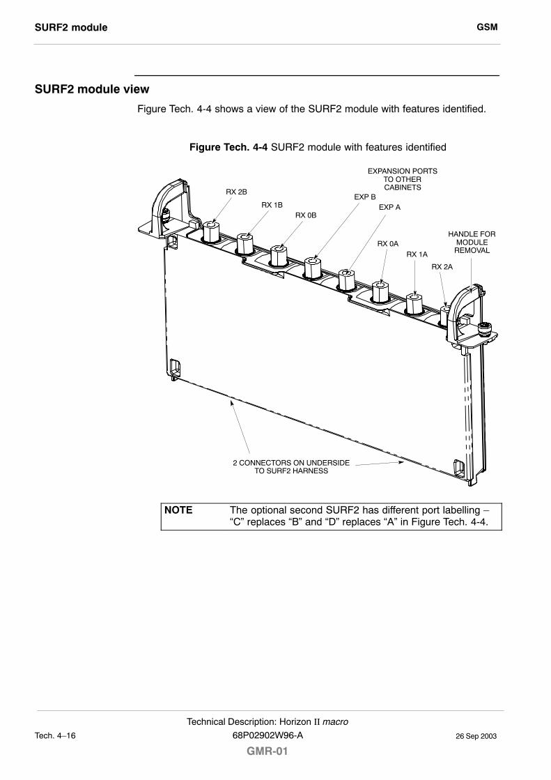
GSMSURF2 module
26 Sep 2003Tech. 4�16
Technical Description: Horizon II macro
GMR-0168P02902W96-A
SURF2 module view
Figure Tech. 4-4 shows a view of the SURF2 module with features identified.
Figure Tech. 4-4 SURF2 module with features identified
RX 1B
RX 2B
RX 0B
RX 0ARX 1A
RX 2A
HANDLE FORMODULEREMOVAL
2 CONNECTORS ON UNDERSIDETO SURF2 HARNESS
EXPANSION PORTSTO OTHERCABINETS
EXP AEXP B
NOTE The optional second SURF2 has different port labelling ��C� replaces �B� and �D� replaces �A� in Figure Tech. 4-4.
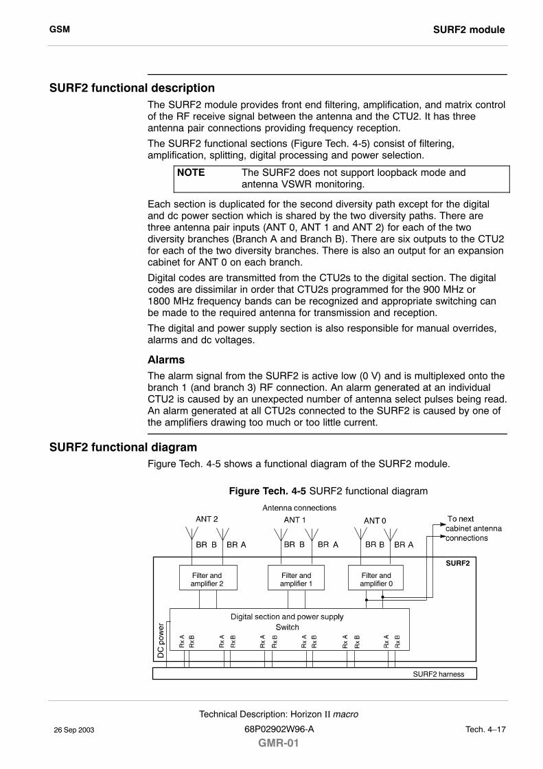
GSM SURF2 module
26 Sep 2003
Technical Description: Horizon II macro
68P02902W96-A
GMR-01Tech. 4�17
SURF2 functional descriptionThe SURF2 module provides front end filtering, amplification, and matrix controlof the RF receive signal between the antenna and the CTU2. It has threeantenna pair connections providing frequency reception.
The SURF2 functional sections (Figure Tech. 4-5) consist of filtering,amplification, splitting, digital processing and power selection.
NOTE The SURF2 does not support loopback mode andantenna VSWR monitoring.
Each section is duplicated for the second diversity path except for the digitaland dc power section which is shared by the two diversity paths. There arethree antenna pair inputs (ANT 0, ANT 1 and ANT 2) for each of the twodiversity branches (Branch A and Branch B). There are six outputs to the CTU2for each of the two diversity branches. There is also an output for an expansioncabinet for ANT 0 on each branch.
Digital codes are transmitted from the CTU2s to the digital section. The digitalcodes are dissimilar in order that CTU2s programmed for the 900 MHz or1800 MHz frequency bands can be recognized and appropriate switching canbe made to the required antenna for transmission and reception.
The digital and power supply section is also responsible for manual overrides,alarms and dc voltages.
AlarmsThe alarm signal from the SURF2 is active low (0 V) and is multiplexed onto thebranch 1 (and branch 3) RF connection. An alarm generated at an individualCTU2 is caused by an unexpected number of antenna select pulses being read.An alarm generated at all CTU2s connected to the SURF2 is caused by one ofthe amplifiers drawing too much or too little current.
SURF2 functional diagramFigure Tech. 4-5 shows a functional diagram of the SURF2 module.
Figure Tech. 4-5 SURF2 functional diagram
SURF2 harness
SURF2
Filter andamplifier 0
Filter andamplifier 1
Filter andamplifier 2
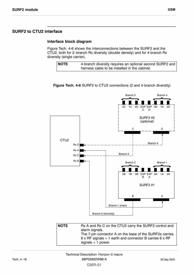
GSMSURF2 module
26 Sep 2003Tech. 4�18
Technical Description: Horizon II macro
GMR-0168P02902W96-A
SURF2 to CTU2 interface
Interface block diagram
Figure Tech. 4-6 shows the interconnections between the SURF2 and theCTU2, both for 2�branch Rx diversity (double density) and for 4-branch Rxdiversity (single carrier).
NOTE 4-branch diversity requires an optional second SURF2 andharness cable to be installed in the cabinet.
Figure Tech. 4-6 SURF2 to CTU2 connections (2 and 4-branch diversity)
Rx D
CTU2
Rx A
Rx C
Rx B
AB
SURF2 #1
2B 1B 0B 0A 1A 2AEXPB
EXPA
DC
SURF2 #2(optional)
2C 1C 0C 0D 1D 2DEXPC
EXPD
Branch 1 (main)
Branch 2 (diversity)
Branch 4
Branch 3
Branch 1Branch 2
Branch 4Branch 3
NOTE Rx A and Rx C on the CTU2 carry the SURF2 control andalarm signals.The 7-pin connector A on the base of the SURF2s carries6 x RF signals + 1 earth and connector B carries 6 x RFsignals + 1 power.
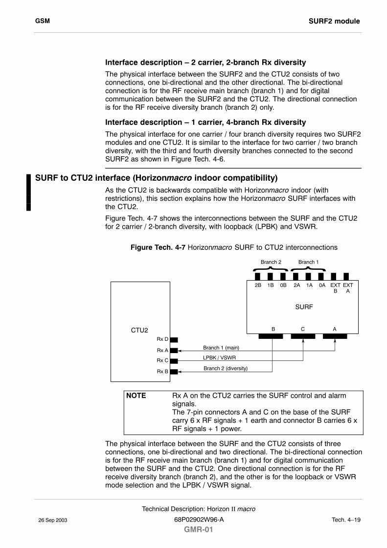
GSM SURF2 module
26 Sep 2003
Technical Description: Horizon II macro
68P02902W96-A
GMR-01Tech. 4�19
Interface description � 2 carrier, 2-branch Rx diversityThe physical interface between the SURF2 and the CTU2 consists of twoconnections, one bi-directional and the other directional. The bi-directionalconnection is for the RF receive main branch (branch 1) and for digitalcommunication between the SURF2 and the CTU2. The directional connectionis for the RF receive diversity branch (branch 2) only.
Interface description � 1 carrier, 4-branch Rx diversity
The physical interface for one carrier / four branch diversity requires two SURF2modules and one CTU2. It is similar to the interface for two carrier / two branchdiversity, with the third and fourth diversity branches connected to the secondSURF2 as shown in Figure Tech. 4-6.
SURF to CTU2 interface (Horizonmacro indoor compatibility)As the CTU2 is backwards compatible with Horizonmacro indoor (withrestrictions), this section explains how the Horizonmacro SURF interfaces withthe CTU2.
Figure Tech. 4-7 shows the interconnections between the SURF and the CTU2for 2 carrier / 2-branch diversity, with loopback (LPBK) and VSWR.
Figure Tech. 4-7 Horizonmacro SURF to CTU2 interconnections
Rx D
CTU2
Rx A
Rx C
Rx B
B A
SURF
2B 1B 0B 2A 1A 0A EXTB
EXTA
Branch 1 (main)
Branch 2 (diversity)
Branch 1Branch 2
C
LPBK / VSWR
NOTE Rx A on the CTU2 carries the SURF control and alarmsignals.The 7-pin connectors A and C on the base of the SURFcarry 6 x RF signals + 1 earth and connector B carries 6 xRF signals + 1 power.
The physical interface between the SURF and the CTU2 consists of threeconnections, one bi-directional and two directional. The bi-directional connectionis for the RF receive main branch (branch 1) and for digital communicationbetween the SURF and the CTU2. One directional connection is for the RFreceive diversity branch (branch 2), and the other is for the loopback or VSWRmode selection and the LPBK / VSWR signal.
GSMTx blocks overview
26 Sep 2003Tech. 4�20
Technical Description: Horizon II macro
GMR-0168P02902W96-A
Tx blocks overview
Introduction to transmit blocks
Transmit (Tx) blocks are located in up to six positions in the basket above theCTU2s. There are three types of internal Tx blocks:
S DUP = Duplexer.
S HCU = Hybrid combiner unit.
S DHU = Dual hybrid combiner unit.
These Tx blocks are cooled by airflow underneath.
Two types of plate can be located in the basket, one as a blanking plate andone to interface CTU2 Tx cables:
S Blanking plate. This ensures proper air flow and EMI shielding for anunused Tx block location in the basket.
S Feedthrough plate. This converts a single SMA connector to a singleN-type connector, used for connecting a Tx cable from a CTU2 to anexpansion cabinet.
CAUTION Unused Tx block locations must be covered with ablanking plate for correct air flow and EMC shielding.
Screw retention in Tx block locations
The HCU, DHU and the blanking or feedthrough plates are secured to the floorof the top panel basket using three M4 screws.
The duplexers are secured to the top surface of the top panel using two M4screws.
To ensure correct EMC shielding and general containment, it is important toensure that all Tx block/plate screw locations have a screw in place andtightened to the correct torque.
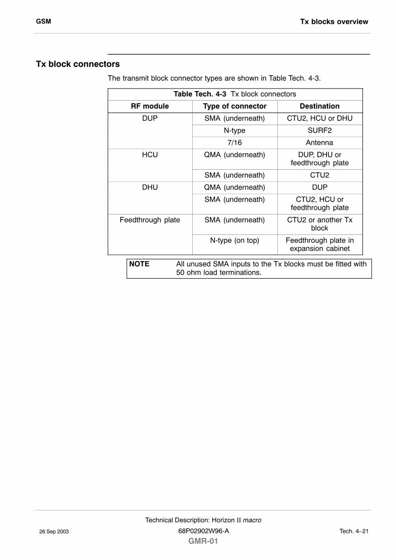
GSM Tx blocks overview
26 Sep 2003
Technical Description: Horizon II macro
68P02902W96-A
GMR-01Tech. 4�21
Tx block connectors
The transmit block connector types are shown in Table Tech. 4-3.
Table Tech. 4-3 Tx block connectors
RF module Type of connector Destination
DUP SMA (underneath) CTU2, HCU or DHU
N-type SURF2
7/16 Antenna
HCU QMA (underneath) DUP, DHU orfeedthrough plate
SMA (underneath) CTU2
DHU QMA (underneath) DUP
SMA (underneath) CTU2, HCU orfeedthrough plate
Feedthrough plate SMA (underneath) CTU2 or another Txblock
N-type (on top) Feedthrough plate inexpansion cabinet
NOTE All unused SMA inputs to the Tx blocks must be fitted with50 ohm load terminations.
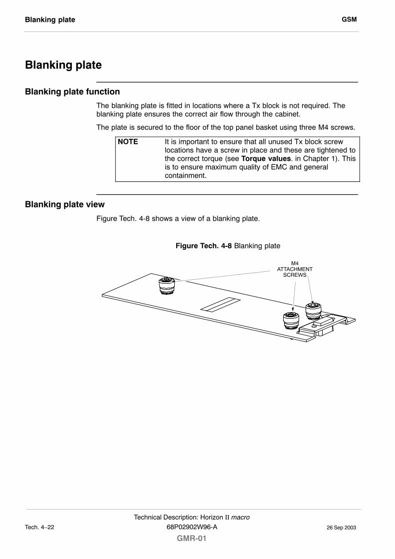
GSMBlanking plate
26 Sep 2003Tech. 4�22
Technical Description: Horizon II macro
GMR-0168P02902W96-A
Blanking plate
Blanking plate function
The blanking plate is fitted in locations where a Tx block is not required. Theblanking plate ensures the correct air flow through the cabinet.
The plate is secured to the floor of the top panel basket using three M4 screws.
NOTE It is important to ensure that all unused Tx block screwlocations have a screw in place and these are tightened tothe correct torque (see Torque values. in Chapter 1). Thisis to ensure maximum quality of EMC and generalcontainment.
Blanking plate view
Figure Tech. 4-8 shows a view of a blanking plate.
Figure Tech. 4-8 Blanking plate
M4ATTACHMENT
SCREWS
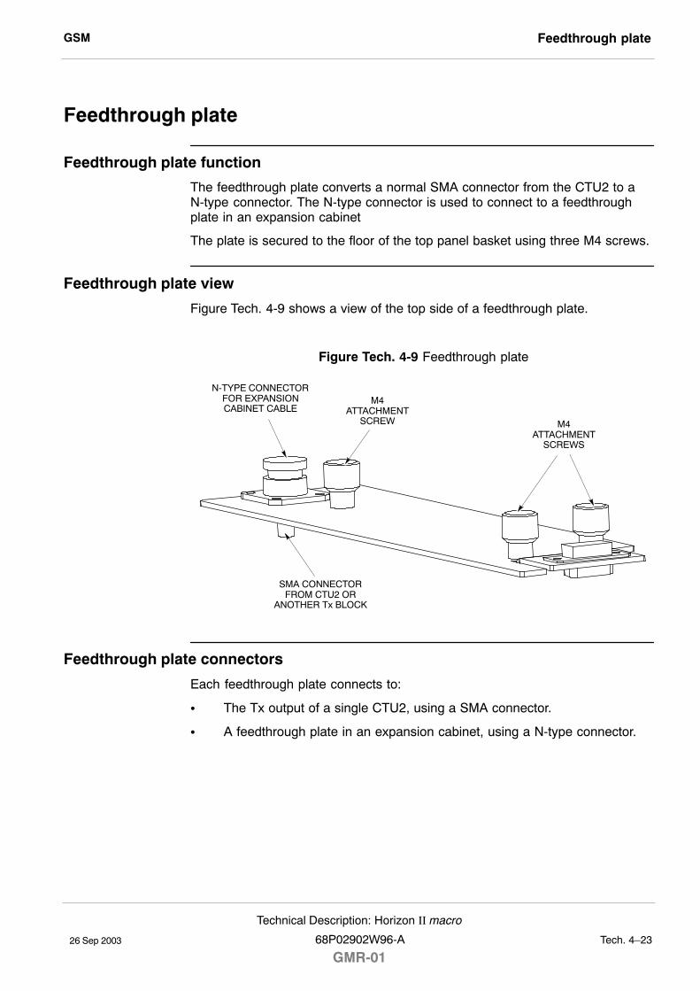
GSM Feedthrough plate
26 Sep 2003
Technical Description: Horizon II macro
68P02902W96-A
GMR-01Tech. 4�23
Feedthrough plate
Feedthrough plate function
The feedthrough plate converts a normal SMA connector from the CTU2 to aN-type connector. The N-type connector is used to connect to a feedthroughplate in an expansion cabinet
The plate is secured to the floor of the top panel basket using three M4 screws.
Feedthrough plate view
Figure Tech. 4-9 shows a view of the top side of a feedthrough plate.
Figure Tech. 4-9 Feedthrough plate
N-TYPE CONNECTORFOR EXPANSIONCABINET CABLE
SMA CONNECTORFROM CTU2 OR
ANOTHER Tx BLOCK
M4ATTACHMENT
SCREW M4ATTACHMENT
SCREWS
Feedthrough plate connectors
Each feedthrough plate connects to:
S The Tx output of a single CTU2, using a SMA connector.
S A feedthrough plate in an expansion cabinet, using a N-type connector.
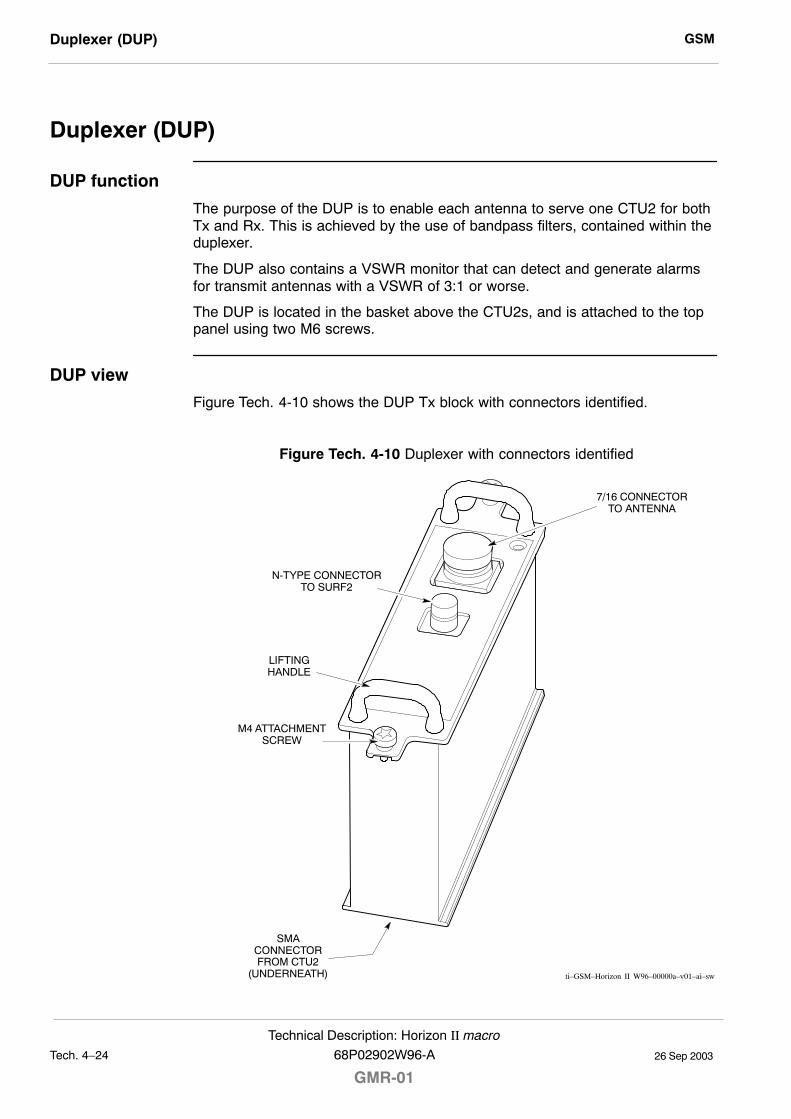
GSMDuplexer (DUP)
26 Sep 2003Tech. 4�24
Technical Description: Horizon II macro
GMR-0168P02902W96-A
Duplexer (DUP)
DUP function
The purpose of the DUP is to enable each antenna to serve one CTU2 for bothTx and Rx. This is achieved by the use of bandpass filters, contained within theduplexer.
The DUP also contains a VSWR monitor that can detect and generate alarmsfor transmit antennas with a VSWR of 3:1 or worse.
The DUP is located in the basket above the CTU2s, and is attached to the toppanel using two M6 screws.
DUP view
Figure Tech. 4-10 shows the DUP Tx block with connectors identified.
Figure Tech. 4-10 Duplexer with connectors identified
ti�GSM�Horizon II W96�00000a�v01�ai�sw
M4 ATTACHMENTSCREW
N-TYPE CONNECTORTO SURF2
7/16 CONNECTORTO ANTENNA
LIFTINGHANDLE
SMACONNECTORFROM CTU2
(UNDERNEATH)
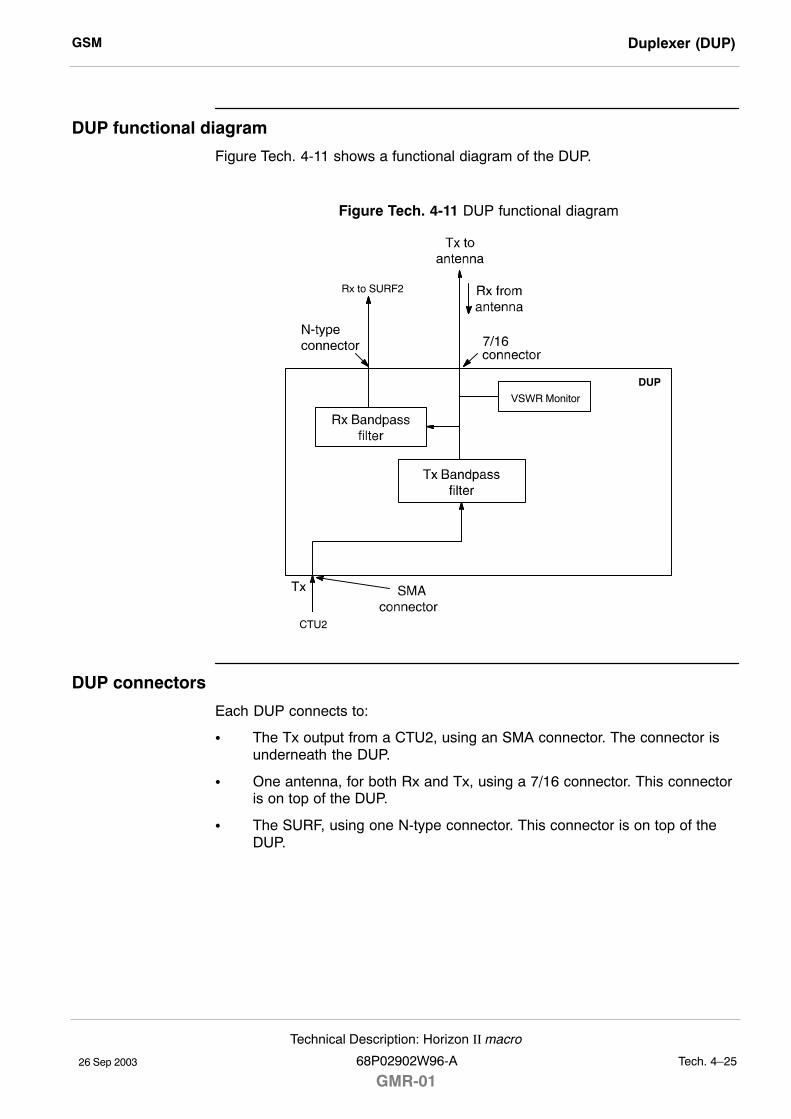
GSM Duplexer (DUP)
26 Sep 2003
Technical Description: Horizon II macro
68P02902W96-A
GMR-01Tech. 4�25
DUP functional diagram
Figure Tech. 4-11 shows a functional diagram of the DUP.
Figure Tech. 4-11 DUP functional diagram
CTU2
DUP
VSWR Monitor
Rx to SURF2
DUP connectors
Each DUP connects to:
S The Tx output from a CTU2, using an SMA connector. The connector isunderneath the DUP.
S One antenna, for both Rx and Tx, using a 7/16 connector. This connectoris on top of the DUP.
S The SURF, using one N-type connector. This connector is on top of theDUP.
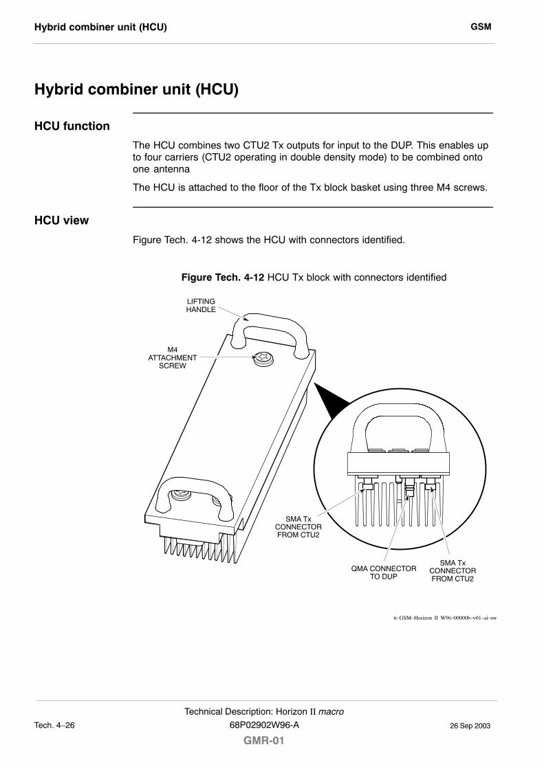
GSMHybrid combiner unit (HCU)
26 Sep 2003Tech. 4�26
Technical Description: Horizon II macro
GMR-0168P02902W96-A
Hybrid combiner unit (HCU)
HCU function
The HCU combines two CTU2 Tx outputs for input to the DUP. This enables upto four carriers (CTU2 operating in double density mode) to be combined ontoone antenna
The HCU is attached to the floor of the Tx block basket using three M4 screws.
HCU view
Figure Tech. 4-12 shows the HCU with connectors identified.
Figure Tech. 4-12 HCU Tx block with connectors identified
M4ATTACHMENT
SCREW
LIFTINGHANDLE
SMA TxCONNECTORFROM CTU2
SMA TxCONNECTORFROM CTU2
QMA CONNECTORTO DUP
ti�GSM�Horizon II W96�00000b�v01�ai�sw
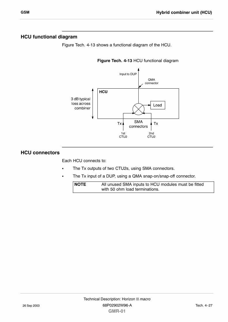
GSM Hybrid combiner unit (HCU)
26 Sep 2003
Technical Description: Horizon II macro
68P02902W96-A
GMR-01Tech. 4�27
HCU functional diagram
Figure Tech. 4-13 shows a functional diagram of the HCU.
Figure Tech. 4-13 HCU functional diagram
Input to DUP
1stCTU2
2ndCTU2
QMAconnector
HCU connectors
Each HCU connects to:
S The Tx outputs of two CTU2s, using SMA connectors.
S The Tx input of a DUP, using a QMA snap-on/snap-off connector.
NOTE All unused SMA inputs to HCU modules must be fittedwith 50 ohm load terminations.
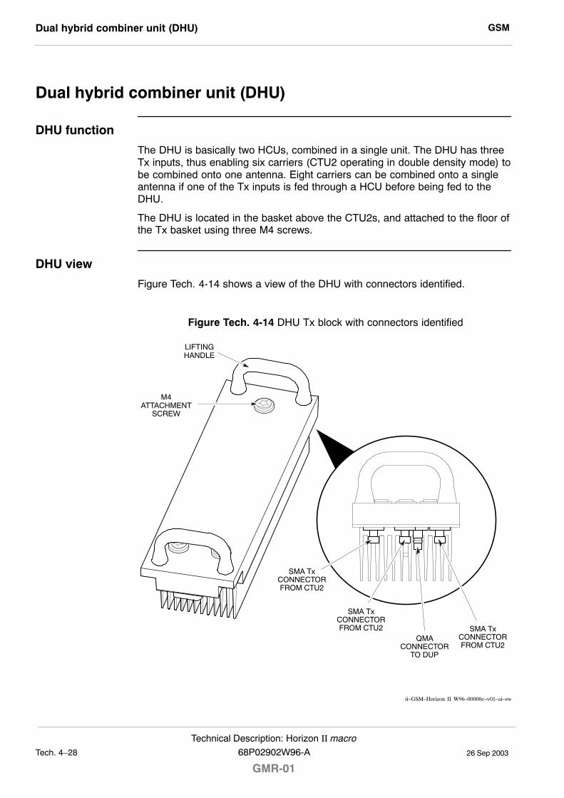
GSMDual hybrid combiner unit (DHU)
26 Sep 2003Tech. 4�28
Technical Description: Horizon II macro
GMR-0168P02902W96-A
Dual hybrid combiner unit (DHU)
DHU function
The DHU is basically two HCUs, combined in a single unit. The DHU has threeTx inputs, thus enabling six carriers (CTU2 operating in double density mode) tobe combined onto one antenna. Eight carriers can be combined onto a singleantenna if one of the Tx inputs is fed through a HCU before being fed to theDHU.
The DHU is located in the basket above the CTU2s, and attached to the floor ofthe Tx basket using three M4 screws.
DHU view
Figure Tech. 4-14 shows a view of the DHU with connectors identified.
Figure Tech. 4-14 DHU Tx block with connectors identified
ti�GSM�Horizon II W96�00000c�v01�ai�sw
M4ATTACHMENT
SCREW
LIFTINGHANDLE
SMA TxCONNECTORFROM CTU2
SMA TxCONNECTORFROM CTU2
QMACONNECTOR
TO DUP
SMA TxCONNECTORFROM CTU2
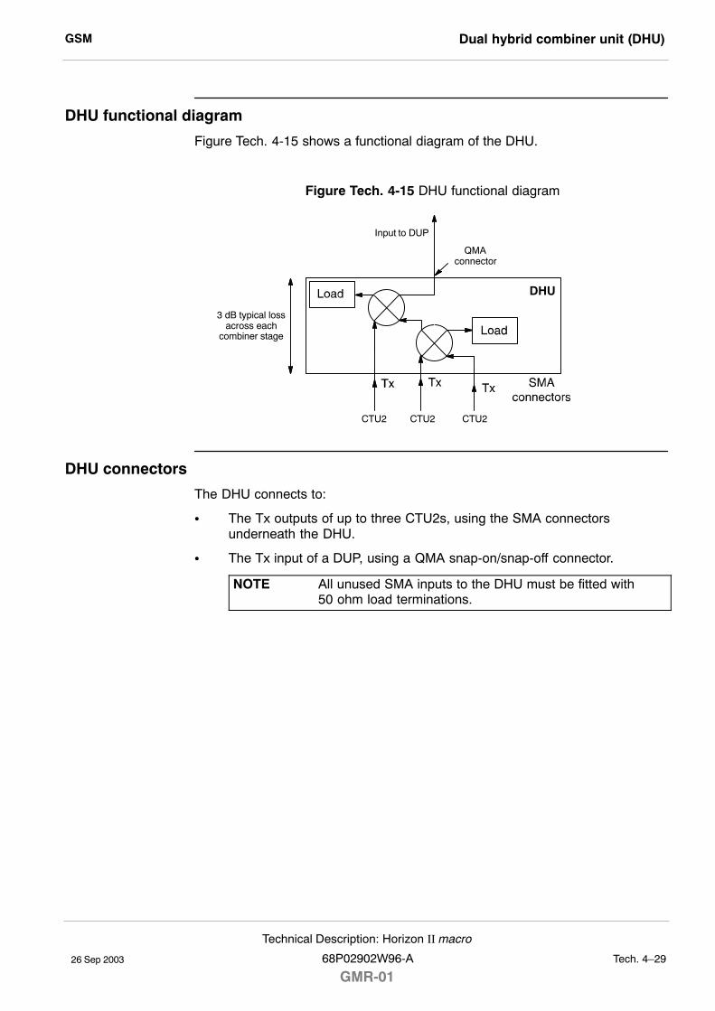
GSM Dual hybrid combiner unit (DHU)
26 Sep 2003
Technical Description: Horizon II macro
68P02902W96-A
GMR-01Tech. 4�29
DHU functional diagram
Figure Tech. 4-15 shows a functional diagram of the DHU.
Figure Tech. 4-15 DHU functional diagram
Input to DUP
CTU2 CTU2
QMAconnector
DHU
CTU2
3 dB typical lossacross each
combiner stage
DHU connectors
The DHU connects to:
S The Tx outputs of up to three CTU2s, using the SMA connectorsunderneath the DHU.
S The Tx input of a DUP, using a QMA snap-on/snap-off connector.
NOTE All unused SMA inputs to the DHU must be fitted with50 ohm load terminations.

GSMDual hybrid combiner unit (DHU)
26 Sep 2003Tech. 4�30
Technical Description: Horizon II macro
GMR-0168P02902W96-A
26 Sep 2003
Technical Description: Horizon II macro
68P02902W96-A
GMR-01Tech. 5�1
Chapter 5
Digital modules

GSM
26 Sep 2003Tech. 5�2
Technical Description: Horizon II macro
GMR-0168P02902W96-A
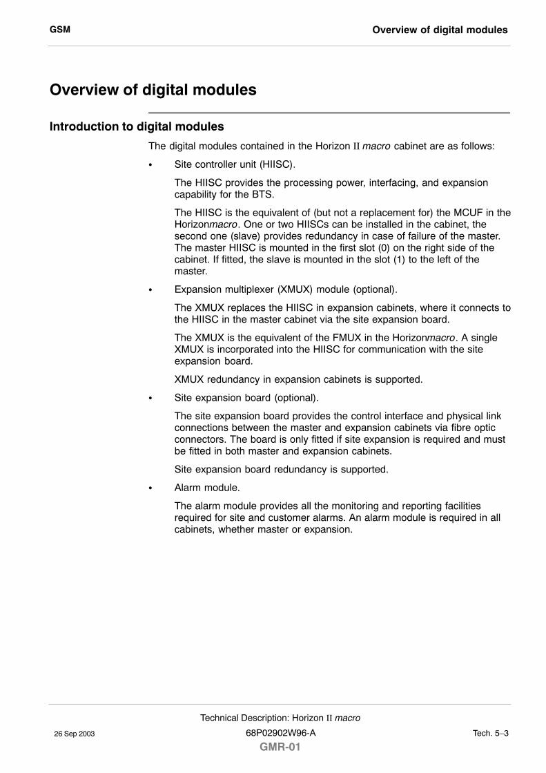
GSM Overview of digital modules
26 Sep 2003
Technical Description: Horizon II macro
68P02902W96-A
GMR-01Tech. 5�3
Overview of digital modules
Introduction to digital modules
The digital modules contained in the Horizon II macro cabinet are as follows:
S Site controller unit (HIISC).
The HIISC provides the processing power, interfacing, and expansioncapability for the BTS.
The HIISC is the equivalent of (but not a replacement for) the MCUF in theHorizonmacro. One or two HIISCs can be installed in the cabinet, thesecond one (slave) provides redundancy in case of failure of the master.The master HIISC is mounted in the first slot (0) on the right side of thecabinet. If fitted, the slave is mounted in the slot (1) to the left of themaster.
S Expansion multiplexer (XMUX) module (optional).
The XMUX replaces the HIISC in expansion cabinets, where it connects tothe HIISC in the master cabinet via the site expansion board.
The XMUX is the equivalent of the FMUX in the Horizonmacro. A singleXMUX is incorporated into the HIISC for communication with the siteexpansion board.
XMUX redundancy in expansion cabinets is supported.
S Site expansion board (optional).
The site expansion board provides the control interface and physical linkconnections between the master and expansion cabinets via fibre opticconnectors. The board is only fitted if site expansion is required and mustbe fitted in both master and expansion cabinets.
Site expansion board redundancy is supported.
S Alarm module.
The alarm module provides all the monitoring and reporting facilitiesrequired for site and customer alarms. An alarm module is required in allcabinets, whether master or expansion.
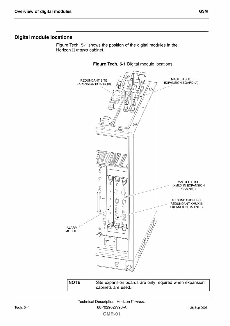
GSMOverview of digital modules
26 Sep 2003Tech. 5�4
Technical Description: Horizon II macro
GMR-0168P02902W96-A
Digital module locations
Figure Tech. 5-1 shows the position of the digital modules in theHorizon II macro cabinet.
Figure Tech. 5-1 Digital module locations
ALARMMODULE
MASTER SITEEXPANSION BOARD (A)
REDUNDANT SITEEXPANSION BOARD (B)
REDUNDANT HIISC(REDUNDANT XMUX INEXPANSION CABINET)
MASTER HIISC(XMUX IN EXPANSION
CABINET)
NOTE Site expansion boards are only required when expansioncabinets are used.
GSM Overview of digital modules
26 Sep 2003
Technical Description: Horizon II macro
68P02902W96-A
GMR-01Tech. 5�5
Redundancy
Redundancy capability for each of the digital modules is described below.
HIISC
The master cabinet must contain at least one HIISC (master), installed asshown in Figure Tech. 5-1. A second HIISC (slave) may also be installed toprovide redundancy.
NOTE Any situation which causes a switch to the redundantHIISC (e.g. master HIISC failure or use of theswap_devices command) will cause a site reset.
XMUX
All expansion cabinets must contain at least one XMUX, installed in the sameslot location as the master HIISC in the master cabinet. A second XMUX mayalso be installed to provide redundancy. XMUX redundancy is coupled toredundancy of the HIISC in the master cabinet; that is, the XMUX is onlyredundant if the HIISC is also redundant.
Site expansion board
A site expansion board is only required when expansion cabinets are used. Insuch cases a site expansion board must be fitted in slot A (see Figure Tech. 5-1)in each cabinet. expansion board redundancy is coupled to HIISC and XMUXredundancy. If the master cabinet has a redundant HIISC and the expansioncabinets have redundant XMUXs, each cabinet (including the master) must alsohave a redundant site expansion board installed in slot B.
Alarm module
An alarm module must be installed in each cabinet, master or slave. Alarmmodule redundancy is not supported.
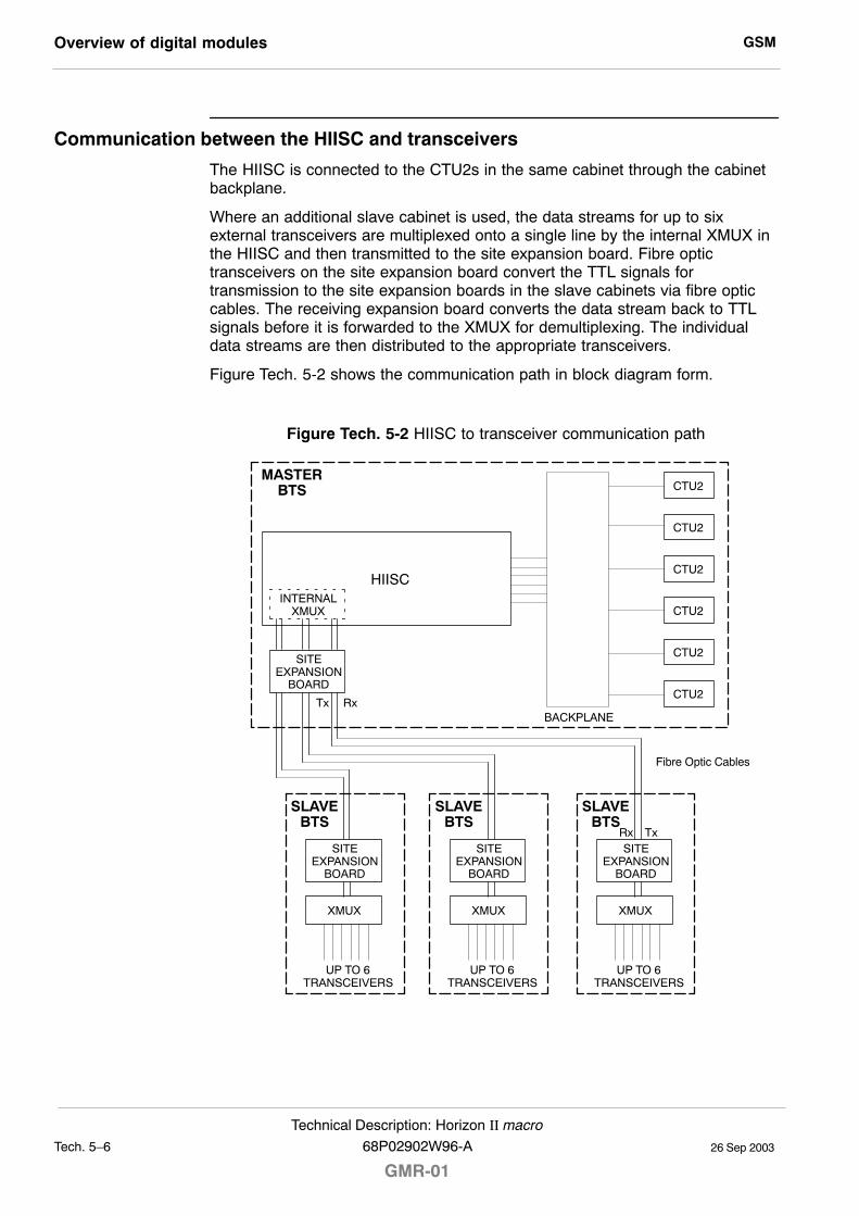
GSMOverview of digital modules
26 Sep 2003Tech. 5�6
Technical Description: Horizon II macro
GMR-0168P02902W96-A
Communication between the HIISC and transceivers
The HIISC is connected to the CTU2s in the same cabinet through the cabinetbackplane.
Where an additional slave cabinet is used, the data streams for up to sixexternal transceivers are multiplexed onto a single line by the internal XMUX inthe HIISC and then transmitted to the site expansion board. Fibre optictransceivers on the site expansion board convert the TTL signals fortransmission to the site expansion boards in the slave cabinets via fibre opticcables. The receiving expansion board converts the data stream back to TTLsignals before it is forwarded to the XMUX for demultiplexing. The individualdata streams are then distributed to the appropriate transceivers.
Figure Tech. 5-2 shows the communication path in block diagram form.
Figure Tech. 5-2 HIISC to transceiver communication path
SLAVEBTS
HIISC
CTU2
SITEEXPANSION
BOARD
INTERNALXMUX
CTU2
CTU2
CTU2
CTU2
CTU2
BACKPLANETx Rx
MASTERBTS
XMUX
UP TO 6TRANSCEIVERS
TxRx
Fibre Optic Cables
SITEEXPANSION
BOARD
SLAVEBTS
XMUX
UP TO 6TRANSCEIVERS
SITEEXPANSION
BOARD
SLAVEBTS
XMUX
UP TO 6TRANSCEIVERS
SITEEXPANSION
BOARD
GSM Horizon II macro site controller (HIISC)
26 Sep 2003
Technical Description: Horizon II macro
68P02902W96-A
GMR-01Tech. 5�7
Horizon II macro site controller (HIISC)
HIISC overview
The HIISC provides all the site processing functions (except for the CTU2 RFfunctions). The functionality of the separate MCUF, NIU, FMUX, and BPSMmodules in the Horizonmacro cabinet are all integrated within the HIISC.
The Horizon II macro cabinet may contain up to two HIISC modules (one masterand one for redundancy). Each site and module has an electronic ID for remoteidentification.
NOTE Although the HIISC provides the equivalent functionality ofthe MCUF in Horizonmacro, it is NOT backwardscompatible and cannot be used in a Horizonmacrocabinet.
The main features of the HIISC are as follows:
S Processors for software and NIU functionality.
S Programmable timeslot interchanger (TSI) that supports the following:
� TDM links for single (legacy) and double density GSM and singledensity EDGE.
� Three expansion links (FMUX equivalent). These links can connectto additional Horizon II macro cabinets (with double density GSM orsingle density EDGE transceivers) or legacy Horizonmacro cabinets(with single/double density GSM or single density EDGEtransceivers).
� BBH routeing for GSM/GPRS (single or double density) or EDGEtransceivers.
S Six integrated E1/T1 span line interfaces. (An upgrade for the CIM/BIM willsupport eight E1/T1 spans on later equipment.)
S Programmable synchronization/timimg block for support of multiple airinterfaces. A GPS interface is included to support Compact EDGE andother air interfaces that require inter-site synchronization.
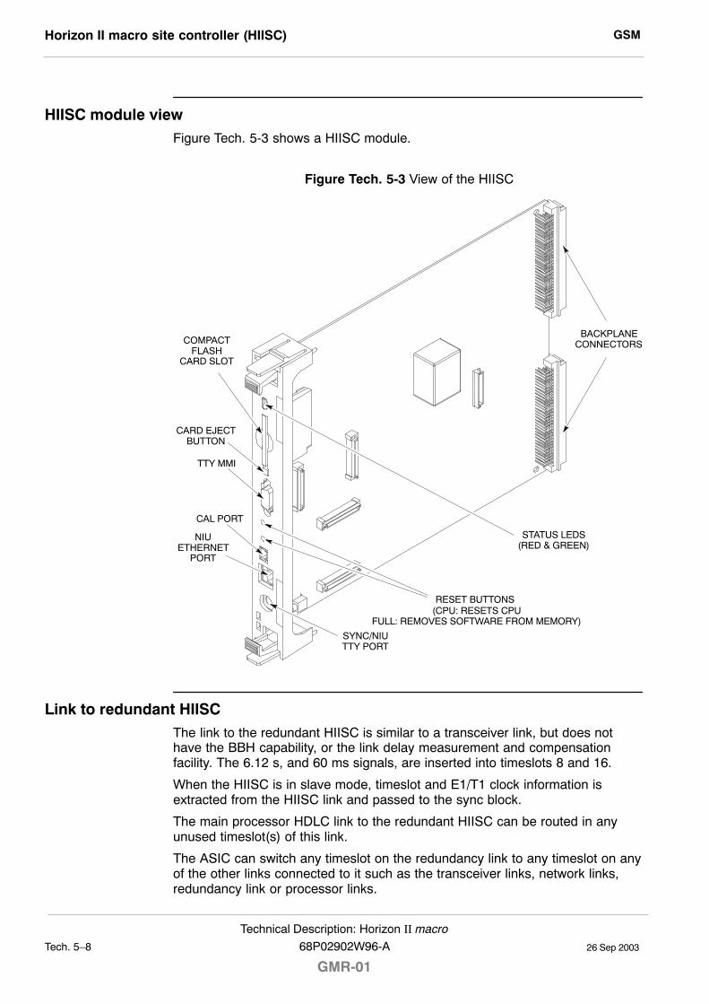
GSMHorizon II macro site controller (HIISC)
26 Sep 2003Tech. 5�8
Technical Description: Horizon II macro
GMR-0168P02902W96-A
HIISC module viewFigure Tech. 5-3 shows a HIISC module.
Figure Tech. 5-3 View of the HIISC
(CPU: RESETS CPUFULL: REMOVES SOFTWARE FROM MEMORY)
COMPACTFLASH
CARD SLOT
STATUS LEDS(RED & GREEN)
CAL PORT
TTY MMI
NIUETHERNET
PORT
SYNC/NIUTTY PORT
RESET BUTTONS
CARD EJECTBUTTON
BACKPLANECONNECTORS
Link to redundant HIISCThe link to the redundant HIISC is similar to a transceiver link, but does nothave the BBH capability, or the link delay measurement and compensationfacility. The 6.12 s, and 60 ms signals, are inserted into timeslots 8 and 16.
When the HIISC is in slave mode, timeslot and E1/T1 clock information isextracted from the HIISC link and passed to the sync block.
The main processor HDLC link to the redundant HIISC can be routed in anyunused timeslot(s) of this link.
The ASIC can switch any timeslot on the redundancy link to any timeslot on anyof the other links connected to it such as the transceiver links, network links,redundancy link or processor links.
GSM Horizon II macro site controller (HIISC)
26 Sep 2003
Technical Description: Horizon II macro
68P02902W96-A
GMR-01Tech. 5�9
Front panel interfaces
Compact flash card interface
The compact flash card slot is located on the front panel of the HIISC, and isused for:
S Code Storage Facility Processor (CSFP) memory.
S Rapid site initialization.
The 32 Mbyte card can be write enabled, for upgrade of site information, ordisabled to protect card use for other sites or secure the site code.
TTY MMI interface
A standard TTY interface is provided on the front panel, of 9.6 kbit/s (8 bits, noparity, 1 stop bit (8 N 1)). A local maintenance terminal can be attached to thisport to use the MMI (Man Machine Interface) of the HIISC.
CAL port
The CAL port on the front panel of the HIISC can be used to calibrate the syncblock clock via MMI commands. The 8 kHz reference output is used in theGCLK calibration procedure (see Chapter 2 of Maintenance and Parts later inthis manual.
NIU ethernet port and SYNC/NIU TTY port
These ports are for Motorola test purposes only.
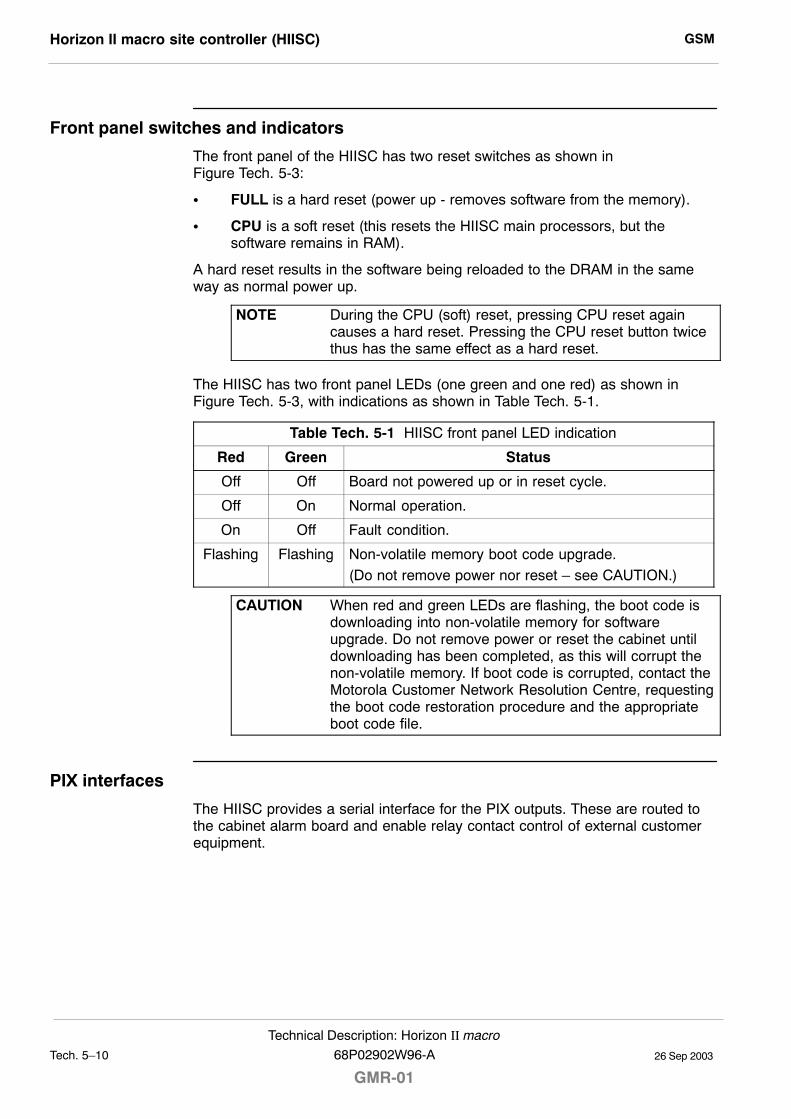
GSMHorizon II macro site controller (HIISC)
26 Sep 2003Tech. 5�10
Technical Description: Horizon II macro
GMR-0168P02902W96-A
Front panel switches and indicators
The front panel of the HIISC has two reset switches as shown inFigure Tech. 5-3:
S FULL is a hard reset (power up - removes software from the memory).
S CPU is a soft reset (this resets the HIISC main processors, but thesoftware remains in RAM).
A hard reset results in the software being reloaded to the DRAM in the sameway as normal power up.
NOTE During the CPU (soft) reset, pressing CPU reset againcauses a hard reset. Pressing the CPU reset button twicethus has the same effect as a hard reset.
The HIISC has two front panel LEDs (one green and one red) as shown inFigure Tech. 5-3, with indications as shown in Table Tech. 5-1.
Table Tech. 5-1 HIISC front panel LED indication
Red Green Status
Off Off Board not powered up or in reset cycle.
Off On Normal operation.
On Off Fault condition.
Flashing Flashing Non-volatile memory boot code upgrade.(Do not remove power nor reset � see CAUTION.)
CAUTION When red and green LEDs are flashing, the boot code isdownloading into non-volatile memory for softwareupgrade. Do not remove power or reset the cabinet untildownloading has been completed, as this will corrupt thenon-volatile memory. If boot code is corrupted, contact theMotorola Customer Network Resolution Centre, requestingthe boot code restoration procedure and the appropriateboot code file.
PIX interfaces
The HIISC provides a serial interface for the PIX outputs. These are routed tothe cabinet alarm board and enable relay contact control of external customerequipment.
GSM Horizon II macro site controller (HIISC)
26 Sep 2003
Technical Description: Horizon II macro
68P02902W96-A
GMR-01Tech. 5�11
SDRAM, flash EPROM and code loading functions
SDRAM
The 32 Mbyte SDRAM provides operational code and data storage for the mainprocessors.
Flash EPROM
The 8 Mbyte flash EPROM has the following functions:
S Storing boot code and executive process code. It has a fast access time(< 75 ns), enabling direct execution. The boot code is factory set, andreprogrammed only in major software upgrades.
S Non-volatile data storage of diagnostic data and module ID information.
Code loading
The boot and executive code held in the flash EPROM initiates the HIISC onpower up or reset. If a compact flash card is fitted, operational code may beobtained and copied to the SDRAM for execution. If no card or code isavailable, the operational code is obtained from the BSC.
Before execution, the operational code held in SDRAM is checked with codeheld at the BSC. The BSC downloads any changed code objects to theSDRAM.
After successful checking of the SDRAM operational code, the code is executedand the compact flash card is updated with any changed objects.
CSFP code loading
If a compact flash card is available, then a code storage facility processor(CSFP) function can be supported. A new software load can be downloaded inthe background, without any reduction in service, and stored on the compactflash card.
Once the complete load has been transferred to the compact flash card, a codeswap can be initiated. The site is reset and the new software brought intoservice (< 10 minutes). As a precaution, the old version is held on the compactflash card to support a roll back to the original version if required.
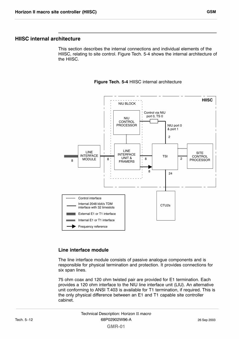
GSMHorizon II macro site controller (HIISC)
26 Sep 2003Tech. 5�12
Technical Description: Horizon II macro
GMR-0168P02902W96-A
HIISC internal architecture
This section describes the internal connections and individual elements of theHIISC, relating to site control. Figure Tech. 5-4 shows the internal architecture ofthe HIISC.
Figure Tech. 5-4 HIISC internal architecture
8 8
2
8
24
2
8
HIISCNIU BLOCK
Control via NIUport 0, TS 0
NIU port 0& port 1
LINEINTERFACE
MODULE
NIUCONTROL
PROCESSOR
LINEINTERFACE
UNIT &FRAMERS
TSISITE
CONTROLPROCESSOR
CTU2s
Control interface
Internal 2048 kbit/s TDMinterface with 32 timeslots
External E1 or T1 interface
Internal E1 or T1 interface
Frequency reference
Line interface module
The line interface module consists of passive analogue components and isresponsible for physical termination and protection. It provides connections forsix span lines.
75 ohm coax and 120 ohm twisted pair are provided for E1 termination. Eachprovides a 120 ohm interface to the NIU line interface unit (LIU). An alternativeunit conforming to ANSI T.403 is available for T1 termination, if required. This isthe only physical difference between an E1 and T1 capable site controllercabinet.
GSM Horizon II macro site controller (HIISC)
26 Sep 2003
Technical Description: Horizon II macro
68P02902W96-A
GMR-01Tech. 5�13
LIU and framers
Dual mode E1/T1 LIU and framers are used, thus permitting the soft selection ofeither E1 or T1 span line connections.
To maintain compatibility with existing GSM BTS and BSC equipment, the linedriver is set for 120 ohm termination for E1 mode and > 600 ft (approx. 183 m)for T1 mode.
The LIU/framer bridges between the internal 32 timeslot 2048 kbit/s TDMhighway and the external E1 2048 kbit/s and T1 1544 kbit/s TDM formats. (ForT1 this is achieved using a timeslot-mapping schema.)
Timeslot interchanger (TSI)
The TSI is controlled by the site control processor (the NIU control processor isnot be equipped with a TSI control interface). A 64 kbit/s timeslot switch isresponsible (within the context of backhaul and RSL requirements) for switchingthe following:
S Timeslots containing TRAU between the CTU2s and NIU framer / LIU.
S Timeslots containing RSL traffic between the NIU framer / LIU and NIUcontrol processor.
S Timeslots containing NIU control messages and RSL traffic stripped ofLAPD between the NIU control processor and the site control processor.
S Inserting 16 kbit/s RSL links into a bit-pair of a designated timeslot.
The use of the TSI in this fashion allows a RSL to be placed into any timeslot(other than timeslot 0 in E1 systems) on any of the 6 spans. The designprovides complete flexibility in the number of timeslots on any span that can beused for RSL traffic. Indeed, all 6 could be placed on a single span. However,each RSL has the limitation that the uplink (BTS to BSC) and downlink (BSC toBTS) timeslot mappings are identical.
NIU control processor and RSL termination
The NIU control processor terminates the LAPD protocol layer for each RSL. Itsupports up to 8 separate and simultaneous LAPD connections. Each LAPDconnection may be configured as either a 64 kbit/s link or as a 16 kbit/s link.
The NIU control processor also configures and monitors the LIU / framer. Tofacilitate these functions the NIU control processor is provisioned with a controlinterface to the LIU / framer and a dual 32 timeslot 2048 kbit/s TDM interface tothe TSI.
The NIU control processor terminates up to 16 full duplex HDLC channels � upto 8 for LAPD transport to the BSC and up to 8 for RSL (including one forcontrol) transport to the site control processor.
Site control processor
The site control processor is provisioned with a control interface for the TSI andtwo 2048 kbit/s TDM interfaces to the TSI. It is responsible for configuration ofthe TSI and control and monitoring of the NIU.
GSMHorizon II macro site controller (HIISC)
26 Sep 2003Tech. 5�14
Technical Description: Horizon II macro
GMR-0168P02902W96-A
NIU control processor to site control processor interfaceThe interface between the NIU control processor and the site control processorconsists of NIU control messages plus RSL messages stripped of the LAPDprotocol. Each RSL connection to the BSC utilizes a 64 kbit/s timeslot betweenthe NIU control processor and the site control processor.
NOTE A 64 kbit/s connection is used, regardless of whether theconnection to the BSC is operating at 64 kbit/s or 16 kbit/s.
NIU control messages, including those used to establish, reconfigure anddisconnect RSL links, are always carried within timeslot 0 on the NIU TDM port0. These messages are multiplexed with traffic comprising the first establishedRSL. The site control processor dynamically assigns additional RSL connectionsto any of the other remaining 31 timeslots of NIU TDM port 0 or 32 timeslots ofNIU TDM port 1.
Daisy chainsThe HIISC supports backhaul daisy chain configurations. Traffic for upstreamsites is routed via the TSI, allowing for multiplexing over shared spans with localsite traffic.
Span type selectionThe NIU defaults to the E1 interface type for all span lines, but supports amessage interface with the site control processor that allows the span type to bechanged to T1.
E1 framing optionsThe NIU can enable and disable timeslot 0 CRC-4 multi-framing (enabled bydefault). Selection is supported by a message interface with the site controlprocessor. In either case, timeslot 16 multi-framing is disabled (allowing timeslot16 to used for TRAU or RSL traffic) and HDB3 line coding is used.
E1 N-bit facilityThe NIU can enable and disable the use E1 N-bits for alarm indications.Selection is supported by a message interface with the site control processor.
T1 framing optionsThe NIU can select either T1 D4 framing with AMI line coding or T1 ESF framingwith B8ZS line coding (default). Selection is supported by a message interfacewith the site control processor.
Timing extractionA 2048/1544 kHz frequency reference and a 125 ms timing reference isextracted by the framer / LIU from each span. This unit also performs jitter andwander attenuation.
Each of the extracted references are fed into a switch that is under site controlprocessor supervision. This is used to select the reference used for phaselocking the SYNC function.
TRAUSpan lines transporting TRAU are switched to the appropriate CTU2 by the TSI.
GSM Horizon II macro site controller (HIISC)
26 Sep 2003
Technical Description: Horizon II macro
68P02902W96-A
GMR-01Tech. 5�15
RSL configuration and control
LAPD links
Each LAPD link is configured with the following default parameters:
T203 = 10 seconds.The maximum I frame size (N201 = 610 bytes).
The site control processor is able to configure the following parameters for eachLAPD connection via the control message interface to the NIU controlprocessor:
Rate (64 kbit/s or 16 kbit/s).Bit-pair for 16 kbit/s connections.SAP.TEI.The maximum number of outstanding I frames (k value).T200.The maximum number of retransmissions (N200).
NOTE The span line timeslot and span line are not required asthe site control processor sets these directly at the TSI.
Additionally, the site control processor specifies the following internal connectionparameters:
NIU port and timeslot for the connection between the NIU controlprocessor and the site control processor.
NIU port and timeslot for the connection between the NIU controlprocessor and the TSI.
16 kbit/s RSLs
Any or all of the 8 RSL links can be configured at either 16 kbit/s or 64 kbit/s.When configured at 16 kbit/s, a RSL occupies a bit-pair within a single timeslot.Four bit-pair positions are supported; bits 0 and 1, bits 2 and 3, bits 4 and 5, bits6 and 7.
For downlink flows, the TSI switches the entire timeslot containing the 16 kbit/sbit-pair onto a NIU port timeslot. The NIU control processor recovers the LAPDfrom the designated bit-pair.
For uplink flows, the NIU control processor places the LAPD within thedesignated bit-pair and timeslot on its TSI connection. The TSI then inserts thisbit-pair into a designated timeslot, while preserving the content of the other sixbits within that timeslot.
RSL and span alarms
LAPD link management events for each LAPD connection and span alarmevents for each span are reported to the site control processor by the NIUcontrol processor.
GSMHorizon II macro site controller (HIISC)
26 Sep 2003Tech. 5�16
Technical Description: Horizon II macro
GMR-0168P02902W96-A
Flow control
The interface between the NIU control processor and the site control processorsupports flow control. This enables the NIU processor to throttle RSL traffic fromthe site control processor in the event of an overload condition. This conditionmay occur when 16 kbit/s RSL links are active or when multiple heavily loaded64 kbit/s RSL links are active.
To reduce the possibility of overloading, the processing delay within the NIUcontrol processor is minimized and the RSL message buffer depth is maximized.A fully loaded NIU (up to 8 established RSL links) maintains a maximumprocessor delay of less than 25 ms per message. Delay is measured fromreceipt of the end of the incoming frame to the start of transmission of theoutgoing frame. The NIU control processor has 2000 kbytes of message buffers.
Integral HIISC XMUX functionality
The equivalent functionality of a separate XMUX module is integrated within theHIISC, thus enabling the HIISC in the master cabinet to communicate with theCTU2s in up to three expansion cabinets via fibre optic links between the siteexpansion boards.
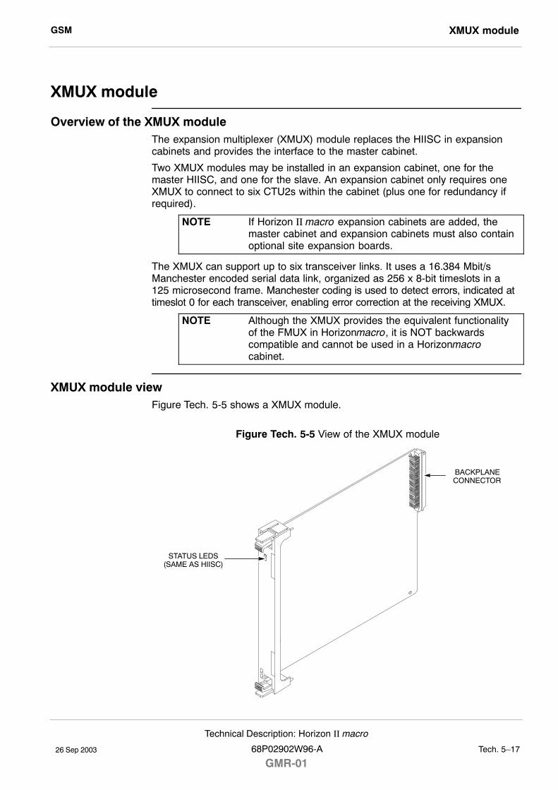
GSM XMUX module
26 Sep 2003
Technical Description: Horizon II macro
68P02902W96-A
GMR-01Tech. 5�17
XMUX module
Overview of the XMUX moduleThe expansion multiplexer (XMUX) module replaces the HIISC in expansioncabinets and provides the interface to the master cabinet.
Two XMUX modules may be installed in an expansion cabinet, one for themaster HIISC, and one for the slave. An expansion cabinet only requires oneXMUX to connect to six CTU2s within the cabinet (plus one for redundancy ifrequired).
NOTE If Horizon II macro expansion cabinets are added, themaster cabinet and expansion cabinets must also containoptional site expansion boards.
The XMUX can support up to six transceiver links. It uses a 16.384 Mbit/sManchester encoded serial data link, organized as 256 x 8-bit timeslots in a125 microsecond frame. Manchester coding is used to detect errors, indicated attimeslot 0 for each transceiver, enabling error correction at the receiving XMUX.
NOTE Although the XMUX provides the equivalent functionalityof the FMUX in Horizonmacro, it is NOT backwardscompatible and cannot be used in a Horizonmacrocabinet.
XMUX module viewFigure Tech. 5-5 shows a XMUX module.
Figure Tech. 5-5 View of the XMUX module
BACKPLANECONNECTOR
STATUS LEDS(SAME AS HIISC)
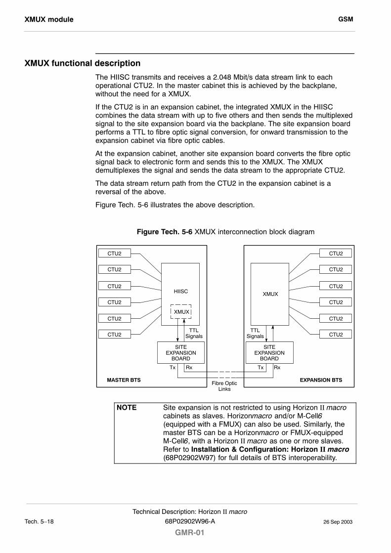
GSMXMUX module
26 Sep 2003Tech. 5�18
Technical Description: Horizon II macro
GMR-0168P02902W96-A
XMUX functional description
The HIISC transmits and receives a 2.048 Mbit/s data stream link to eachoperational CTU2. In the master cabinet this is achieved by the backplane,without the need for a XMUX.
If the CTU2 is in an expansion cabinet, the integrated XMUX in the HIISCcombines the data stream with up to five others and then sends the multiplexedsignal to the site expansion board via the backplane. The site expansion boardperforms a TTL to fibre optic signal conversion, for onward transmission to theexpansion cabinet via fibre optic cables.
At the expansion cabinet, another site expansion board converts the fibre opticsignal back to electronic form and sends this to the XMUX. The XMUXdemultiplexes the signal and sends the data stream to the appropriate CTU2.
The data stream return path from the CTU2 in the expansion cabinet is areversal of the above.
Figure Tech. 5-6 illustrates the above description.
Figure Tech. 5-6 XMUX interconnection block diagram
CTU2
Rx
CTU2
CTU2
CTU2
CTU2
CTU2
HIISC
XMUX
SITEEXPANSION
BOARD
Tx
CTU2
Rx
CTU2
CTU2
CTU2
CTU2
CTU2
XMUX
SITEEXPANSION
BOARD
Tx
MASTER BTS EXPANSION BTSFibre Optic
Links
TTLSignals
TTLSignals
NOTE Site expansion is not restricted to using Horizon II macrocabinets as slaves. Horizonmacro and/or M-Cell6(equipped with a FMUX) can also be used. Similarly, themaster BTS can be a Horizonmacro or FMUX-equippedM-Cell6, with a Horizon II macro as one or more slaves.Refer to Installation & Configuration: Horizon II macro(68P02902W97) for full details of BTS interoperability.
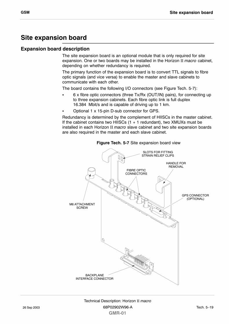
GSM Site expansion board
26 Sep 2003
Technical Description: Horizon II macro
68P02902W96-A
GMR-01Tech. 5�19
Site expansion board
Expansion board descriptionThe site expansion board is an optional module that is only required for siteexpansion. One or two boards may be installed in the Horizon II macro cabinet,depending on whether redundancy is required.
The primary function of the expansion board is to convert TTL signals to fibreoptic signals (and vice versa) to enable the master and slave cabinets tocommunicate with each other.
The board contains the following I/O connectors (see Figure Tech. 5-7):
S 6 x fibre optic connectors (three Tx/Rx (OUT/IN) pairs), for connecting upto three expansion cabinets. Each fibre optic link is full duplex16.384 Mbit/s and is capable of driving up to 1 km.
S Optional 1 x 15-pin D-sub connector for GPS.
Redundancy is determined by the complement of HIISCs in the master cabinet.If the cabinet contains two HIISCs (1 + 1 redundant), two XMUXs must beinstalled in each Horizon II macro slave cabinet and two site expansion boardsare also required in the master and each slave cabinet.
Figure Tech. 5-7 Site expansion board view
GPS CONNECTOR(OPTIONAL)
FIBRE OPTICCONNECTORS
BACKPLANEINTERFACE CONNECTOR
M6 ATTACHMENTSCREW
HANDLE FORREMOVAL
SLOTS FOR FITTINGSTRAIN RELIEF CLIPS
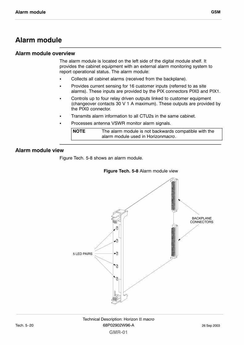
GSMAlarm module
26 Sep 2003Tech. 5�20
Technical Description: Horizon II macro
GMR-0168P02902W96-A
Alarm module
Alarm module overviewThe alarm module is located on the left side of the digital module shelf. Itprovides the cabinet equipment with an external alarm monitoring system toreport operational status. The alarm module:
S Collects all cabinet alarms (received from the backplane).
S Provides current sensing for 16 customer inputs (referred to as sitealarms). These inputs are provided by the PIX connectors PIX0 and PIX1.
S Controls up to four relay driven outputs linked to customer equipment(changeover contacts 30 V 1 A maximum). These outputs are provided bythe PIX0 connector.
S Transmits alarm information to all CTU2s in the same cabinet.
S Processes antenna VSWR monitor alarm signals.
NOTE The alarm module is not backwards compatible with thealarm module used in Horizonmacro.
Alarm module viewFigure Tech. 5-8 shows an alarm module.
Figure Tech. 5-8 Alarm module view
BACKPLANECONNECTORS
5 LED PAIRS
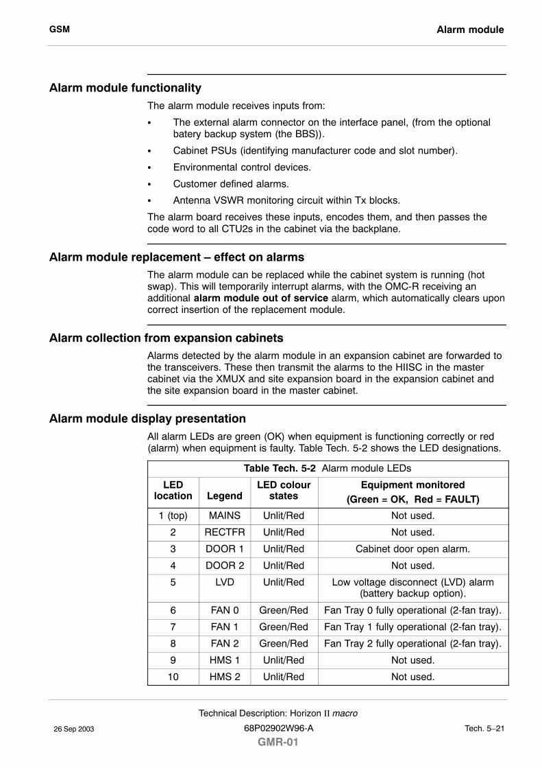
GSM Alarm module
26 Sep 2003
Technical Description: Horizon II macro
68P02902W96-A
GMR-01Tech. 5�21
Alarm module functionalityThe alarm module receives inputs from:
S The external alarm connector on the interface panel, (from the optionalbatery backup system (the BBS)).
S Cabinet PSUs (identifying manufacturer code and slot number).
S Environmental control devices.
S Customer defined alarms.
S Antenna VSWR monitoring circuit within Tx blocks.
The alarm board receives these inputs, encodes them, and then passes thecode word to all CTU2s in the cabinet via the backplane.
Alarm module replacement � effect on alarmsThe alarm module can be replaced while the cabinet system is running (hotswap). This will temporarily interrupt alarms, with the OMC-R receiving anadditional alarm module out of service alarm, which automatically clears uponcorrect insertion of the replacement module.
Alarm collection from expansion cabinetsAlarms detected by the alarm module in an expansion cabinet are forwarded tothe transceivers. These then transmit the alarms to the HIISC in the mastercabinet via the XMUX and site expansion board in the expansion cabinet andthe site expansion board in the master cabinet.
Alarm module display presentationAll alarm LEDs are green (OK) when equipment is functioning correctly or red(alarm) when equipment is faulty. Table Tech. 5-2 shows the LED designations.
Table Tech. 5-2 Alarm module LEDs
LEDlocation Legend
LED colourstates
Equipment monitored(Green = OK, Red = FAULT)
1 (top) MAINS Unlit/Red Not used.
2 RECTFR Unlit/Red Not used.
3 DOOR 1 Unlit/Red Cabinet door open alarm.
4 DOOR 2 Unlit/Red Not used.
5 LVD Unlit/Red Low voltage disconnect (LVD) alarm(battery backup option).
6 FAN 0 Green/Red Fan Tray 0 fully operational (2-fan tray).
7 FAN 1 Green/Red Fan Tray 1 fully operational (2-fan tray).
8 FAN 2 Green/Red Fan Tray 2 fully operational (2-fan tray).
9 HMS 1 Unlit/Red Not used.
10 HMS 2 Unlit/Red Not used.

GSMAlarm module
26 Sep 2003Tech. 5�22
Technical Description: Horizon II macro
GMR-0168P02902W96-A

CHAPTER 2FRU REPLACEMENT
CHAPTER 3SITE VERIFICATION
CHAPTER 4PARTS LISTS
CHAPTER 1 ROUTINE MAINTENANCE


26 Sep 2003
Maintenance and Parts: Horizon II macro
68P02902W96-A
GMR-01i
Maintenance and Parts (Maint.)

GSM
26 Sep 2003ii
Maintenance and Parts: Horizon II macro
GMR-0168P02902W96-A
26 Sep 2003
Maintenance and Parts: Horizon II macro
68P02902W96-A
GMR-01Maint. 1�1
Chapter 1
Routine maintenance

GSM
26 Sep 2003Maint. 1�2
Maintenance and Parts: Horizon II macro
GMR-0168P02902W96-A
GSM Routine maintenance overview
26 Sep 2003
Maintenance and Parts: Horizon II macro
68P02902W96-A
GMR-01Maint. 1�3
Routine maintenance overview
In this chapter
This chapter contains the procedures for the routine maintenance of aHorizon II macro base transceiver station (BTS).
NOTE Since a Horizon II macro BTS operates as part of anetwork, the procedures in this chapter must be performedin conjunction with the relevant network procedures in theassociated OMC-R manuals. Before attempting any workon the cabinet, contact the OMC-R to advise on theproposed activity.
Safety
WARNING Potentially lethal voltages and high energy sources arepresent in the cabinet when the external ac mains isolatorswitch is set to the on position and/or batteries areconnected. Remove rings, watches and jewellery beforestarting these procedures, and exercise extreme cautionwhen working on the equipment.Maintenance procedures on this equipment must only becarried out by suitably qualified personnel.
Safety features are built into the equipment to protect against the potentiallylethal hazards that exist. All statements regarding safety within these routinemaintenance procedures must be adhered to when working on the equipment.
Reporting faulty devices
During routine maintenance and FRU replacement procedures, it may bepossible to identify signs of damage that might indicate a problem that couldrepeat, cause additional damage, or be a symptom of a failure elsewhere.Analysis of the problem may identify the fault and make corrective actionpossible.
Whenever a safety issue arises:
S Inform the OMC-R that an equipment safety problem has been identified.
S Make the equipment concerned safe, for example, by removing power.
S Make no further attempt to tamper with the equipment..
S Report the problem directly to GSM Customer Network Resolution Centre+44 (0)1793 565444 (telephone) and follow up with a written report by fax+44 (0)1793 430987 (fax).
S Collect evidence from the equipment under the guidance of the CustomerNetwork Resolution Centre.
S Seek local office advice.
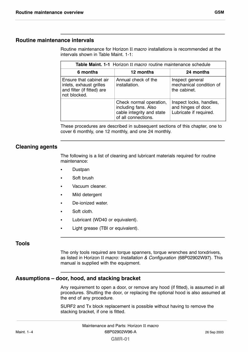
GSMRoutine maintenance overview
26 Sep 2003Maint. 1�4
Maintenance and Parts: Horizon II macro
GMR-0168P02902W96-A
Routine maintenance intervals
Routine maintenance for Horizon II macro installations is recommended at theintervals shown in Table Maint. 1-1:
Table Maint. 1-1 Horizon II macro routine maintenance schedule
6 months 12 months 24 months
Ensure that cabinet airinlets, exhaust grillesand filter (if fitted) arenot blocked.
Annual check of theinstallation.
Inspect generalmechanical condition ofthe cabinet.
Check normal operation,including fans. Alsocable integrity and stateof all connections.
Inspect locks, handles,and hinges of door.Lubricate if required.
These procedures are described in subsequent sections of this chapter, one tocover 6 monthly, one 12 monthly, and one 24 monthly.
Cleaning agents
The following is a list of cleaning and lubricant materials required for routinemaintenance:
S Dustpan
S Soft brush
S Vacuum cleaner.
S Mild detergent
S De-ionized water.
S Soft cloth.
S Lubricant (WD40 or equivalent).
S Light grease (TBI or equivalent).
Tools
The only tools required are torque spanners, torque wrenches and torxdrivers,as listed in Horizon II macro: Installation & Configuration (68P02902W97). Thismanual is supplied with the equipment.
Assumptions � door, hood, and stacking bracket
Any requirement to open a door, or remove any hood (if fitted), is assumed in allprocedures. Shutting the door, or replacing the optional hood is also assumed atthe end of any procedure.
SURF2 and Tx block replacement is possible without having to remove thestacking bracket, if one is fitted.
GSM Routine maintenance overview
26 Sep 2003
Maintenance and Parts: Horizon II macro
68P02902W96-A
GMR-01Maint. 1�5
Door operation
The door lock is a trigger latch. To operate the door:
1. Insert the correct key into the lock and turn.
2. Press the middle square panel by the lock to release the lock.
3. Open the door to the initial detent position at 95_.
CAUTION Avoid damaging honeycomb door vent.
NOTE If the equipment is active, a door open alarm will besignalled to the OMC-R.
4. To open the door to the maximum 150_, simply pull the door until itreaches the limit of movement.
5. To close, simply push the door to the closed position and then lock.
Hood removal and refitting
The optional hood is held in place by four pins. Remove by lifting the hood rearedge until free of the pins, then lift off.
To fit the optional hood, align the hood to the back pins, lower hood onto thepins, and press down firmly.
Stacking bracket removal
The stacking bracket is secured by eight M8 screws (including four which can bereplaced by pins if the optional hood is fitted). To remove or replace a stackingbracket, see Replacing a stacking bracket in Chapter 2.
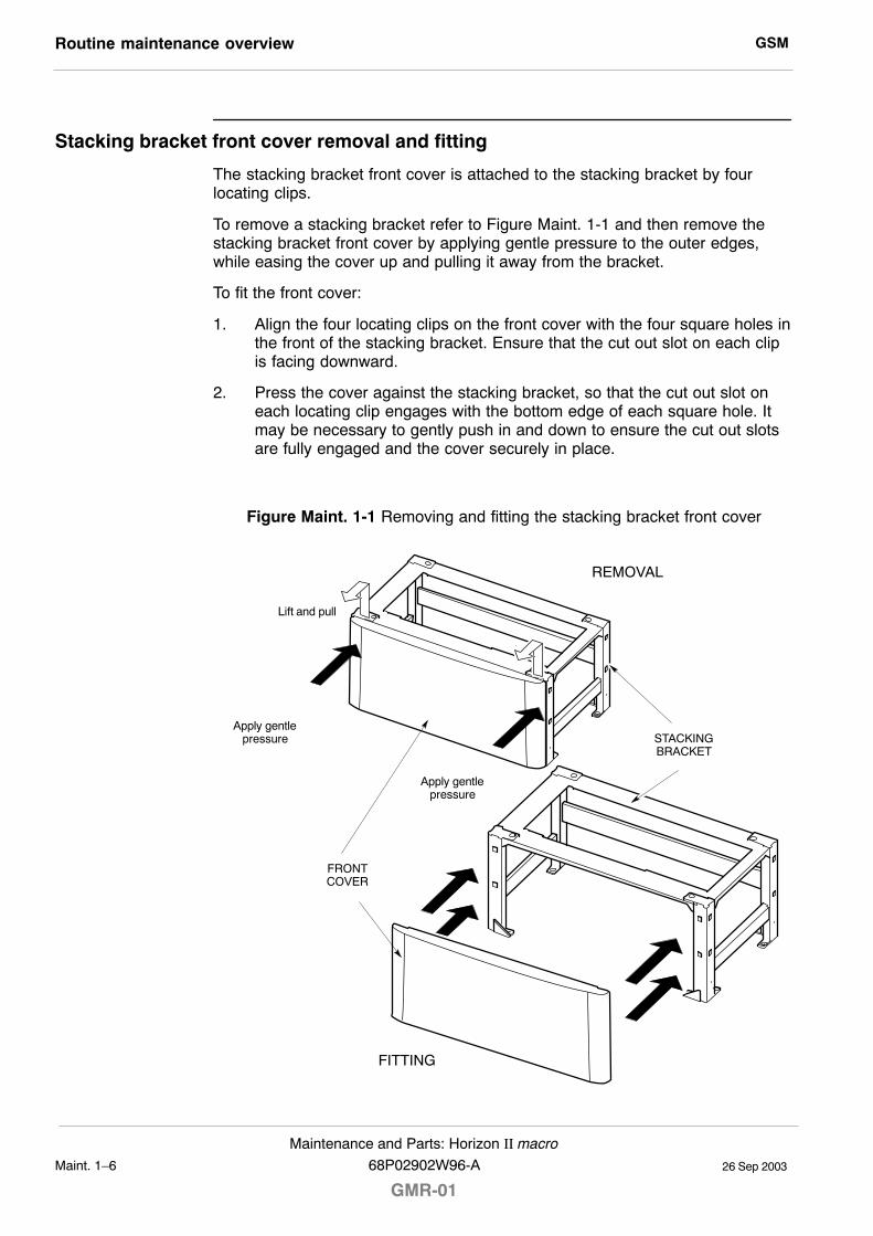
GSMRoutine maintenance overview
26 Sep 2003Maint. 1�6
Maintenance and Parts: Horizon II macro
GMR-0168P02902W96-A
Stacking bracket front cover removal and fitting
The stacking bracket front cover is attached to the stacking bracket by fourlocating clips.
To remove a stacking bracket refer to Figure Maint. 1-1 and then remove thestacking bracket front cover by applying gentle pressure to the outer edges,while easing the cover up and pulling it away from the bracket.
To fit the front cover:
1. Align the four locating clips on the front cover with the four square holes inthe front of the stacking bracket. Ensure that the cut out slot on each clipis facing downward.
2. Press the cover against the stacking bracket, so that the cut out slot oneach locating clip engages with the bottom edge of each square hole. Itmay be necessary to gently push in and down to ensure the cut out slotsare fully engaged and the cover securely in place.
Figure Maint. 1-1 Removing and fitting the stacking bracket front cover
REMOVAL
FITTING
FRONTCOVER
STACKINGBRACKET
Lift and pull
Apply gentlepressure
Apply gentlepressure
GSM 6-monthly maintenance procedures
26 Sep 2003
Maintenance and Parts: Horizon II macro
68P02902W96-A
GMR-01Maint. 1�7
6-monthly maintenance procedures
Type of procedures
The 6-monthly maintenance procedures involve the following:
S Cleaning air inlets and exhaust grilles.
S Examining and, if necessary, replacing the optional air filter.
WARNING Potentially lethal voltages and high energy sources arepresent in the cabinet when the external ac mains isolatorswitch is set to the on position and/or batteries areconnected. Remove rings, watches and jewellery beforestarting these procedures, and exercise extreme cautionwhen working on the equipment.
Cleaning inlets and exhaust grilles
CAUTION If the cabinet is operational, this maintenance procedureshould be completed as quickly as possible, in order tominimize duration of air cooling disruption.
Inlets are along the back, sides and front at the base of the cabinet. Air isexpelled through the door vent and through the top panel.
The following procedure should be followed to clean inlet and outlet grilles:
S Use a vacuum cleaner or brush to ensure the bottom inlets are clear ofdebris.
S Open the door and clean the aluminium door vent, taking care to avoiddamage.
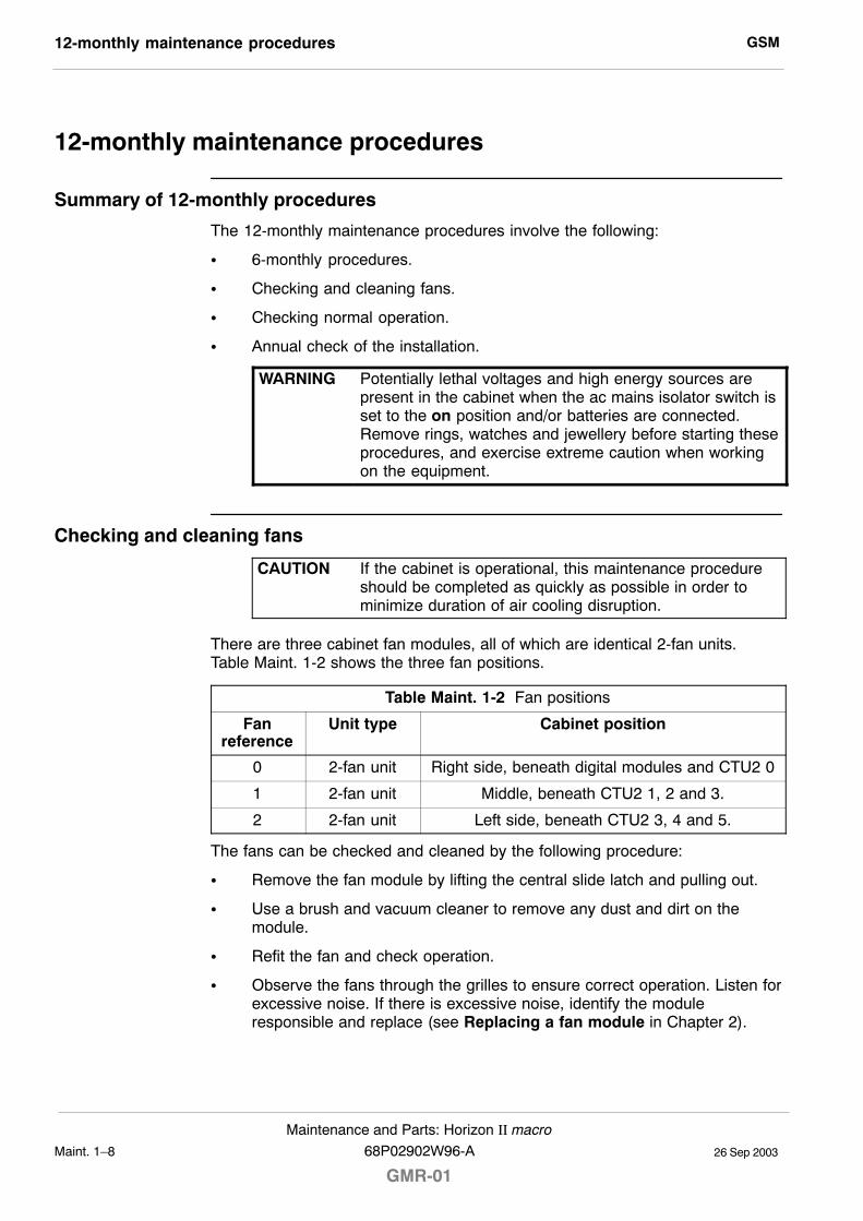
GSM12-monthly maintenance procedures
26 Sep 2003Maint. 1�8
Maintenance and Parts: Horizon II macro
GMR-0168P02902W96-A
12-monthly maintenance procedures
Summary of 12-monthly procedures
The 12-monthly maintenance procedures involve the following:
S 6-monthly procedures.
S Checking and cleaning fans.
S Checking normal operation.
S Annual check of the installation.
WARNING Potentially lethal voltages and high energy sources arepresent in the cabinet when the ac mains isolator switch isset to the on position and/or batteries are connected.Remove rings, watches and jewellery before starting theseprocedures, and exercise extreme caution when workingon the equipment.
Checking and cleaning fans
CAUTION If the cabinet is operational, this maintenance procedureshould be completed as quickly as possible in order tominimize duration of air cooling disruption.
There are three cabinet fan modules, all of which are identical 2-fan units.Table Maint. 1-2 shows the three fan positions.
Table Maint. 1-2 Fan positions
Fanreference
Unit type Cabinet position
0 2-fan unit Right side, beneath digital modules and CTU2 0
1 2-fan unit Middle, beneath CTU2 1, 2 and 3.
2 2-fan unit Left side, beneath CTU2 3, 4 and 5.
The fans can be checked and cleaned by the following procedure:
S Remove the fan module by lifting the central slide latch and pulling out.
S Use a brush and vacuum cleaner to remove any dust and dirt on themodule.
S Refit the fan and check operation.
S Observe the fans through the grilles to ensure correct operation. Listen forexcessive noise. If there is excessive noise, identify the moduleresponsible and replace (see Replacing a fan module in Chapter 2).
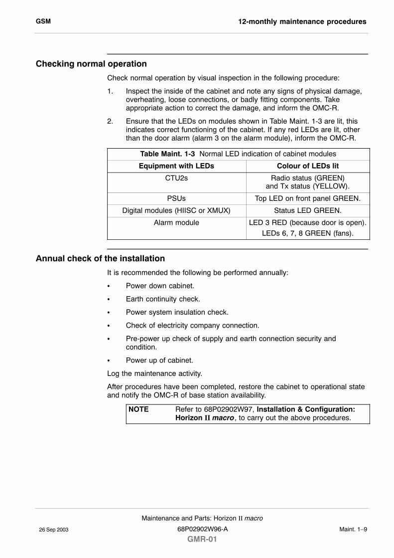
GSM 12-monthly maintenance procedures
26 Sep 2003
Maintenance and Parts: Horizon II macro
68P02902W96-A
GMR-01Maint. 1�9
Checking normal operation
Check normal operation by visual inspection in the following procedure:
1. Inspect the inside of the cabinet and note any signs of physical damage,overheating, loose connections, or badly fitting components. Takeappropriate action to correct the damage, and inform the OMC-R.
2. Ensure that the LEDs on modules shown in Table Maint. 1-3 are lit, thisindicates correct functioning of the cabinet. If any red LEDs are lit, otherthan the door alarm (alarm 3 on the alarm module), inform the OMC-R.
Table Maint. 1-3 Normal LED indication of cabinet modules
Equipment with LEDs Colour of LEDs lit
CTU2s Radio status (GREEN)and Tx status (YELLOW).
PSUs Top LED on front panel GREEN.
Digital modules (HIISC or XMUX) Status LED GREEN.
Alarm module LED 3 RED (because door is open).
LEDs 6, 7, 8 GREEN (fans).
Annual check of the installation
It is recommended the following be performed annually:
S Power down cabinet.
S Earth continuity check.
S Power system insulation check.
S Check of electricity company connection.
S Pre-power up check of supply and earth connection security andcondition.
S Power up of cabinet.
Log the maintenance activity.
After procedures have been completed, restore the cabinet to operational stateand notify the OMC-R of base station availability.
NOTE Refer to 68P02902W97, Installation & Configuration:Horizon II macro, to carry out the above procedures.
GSM24-monthly maintenance procedures
26 Sep 2003Maint. 1�10
Maintenance and Parts: Horizon II macro
GMR-0168P02902W96-A
24-monthly maintenance procedures
Summary of 24-monthly procedures
WARNING Potentially lethal voltages and high energy sources arepresent in the cabinet when the ac mains isolator switch isset to the on position and/or batteries are connected.Remove rings, watches and jewellery before starting theseprocedures, and exercise extreme caution when workingon the equipment.
The 24-monthly maintenance procedures involve the following:
S 6-monthly procedures.
S 12-monthly procedures.
S Mechanical inspection of cabinet, including inspection and lubrication oflocks and hinges.
Mechanical inspection of cabinet, locks and hinges
The following must be performed every 24 months.
Inspecting the cabinet exterior
NOTE Use a step ladder or platform for access to a stackedcabinet, where necessary.
To inspect the cabinet exterior:
S Check exterior panels and hood/stacking bracket for dents and structuraldamage.
S Check cabinet top connections for signs of overheating and security ofattachment.
Inspecting the door
To inspect the door:
S Check the cabinet door for distortion, security and correct operation.
S Check the hinges for damage, security and correct operation. Carefullylubricate the hinges. Ensure that all door seals are wiped clean of thelubricant.
S Check the earth connection for damage and security.
S Check the door lock mechanism and inspect for ease of operation.Lubricate the mechanism with light grease. Ensure that lubricated surfacesare grit-free.
GSM 24-monthly maintenance procedures
26 Sep 2003
Maintenance and Parts: Horizon II macro
68P02902W96-A
GMR-01Maint. 1�11
Inspecting the cabinet interior
To inspect the cabinet interior:
S Check all rack equipment for security of attachment, especially PSU, CBCand CTU2 attachment screws using a torxdriver. Tighten to the correcttorque (see Table Maint. 2-1 in Chapter 2 for torque values).
S Carry out a visual check of all wiring for signs of overheating and securityof attachment.
WARNING Do not overstress the earth connections as this maydamage the connector and reduce the protective function.
S Check the earth connections for corrosion and tightness using a torquespanner. Tighten to the correct torque.

GSM24-monthly maintenance procedures
26 Sep 2003Maint. 1�12
Maintenance and Parts: Horizon II macro
GMR-0168P02902W96-A
26 Sep 2003
Maintenance and Parts: Horizon II macro
68P02902W96-A
GMR-01Maint. 2�1
Chapter 2
FRU replacement procedures

GSM
26 Sep 2003Maint. 2�2
Maintenance and Parts: Horizon II macro
GMR-0168P02902W96-A
GSM Overview of replacement procedures
26 Sep 2003
Maintenance and Parts: Horizon II macro
68P02902W96-A
GMR-01Maint. 2�3
Overview of replacement procedures
Field replaceable units (FRUs)
WARNING Potentially lethal voltages and high energy sources arepresent in the cabinet when the external isolator switch isset to the on position and/or batteries are connected.Remove rings, watches and jewellery before starting theseprocedures, and exercise extreme caution when workingon the equipment.Maintenance procedures on this equipment must only becarried out by suitably qualified personnel.
This chapter provides information on the replacement of FRUs. Only thosecomponents classed as FRUs are covered in this chapter.
Any requirement to open or close a door, or remove and replace the optionalhood, is assumed in procedures. Shutting the door, or replacing the hood isassumed at the end of any procedure. SURF2 module and Tx blockreplacement may be carried out with a stacking bracket in place. For dooropening or stacking bracket front panel removal, refer to Chapter 1, Routinemaintenance.
Where customers wish to perform a minor repair on a FRU in order to save thecost of full replacement, they should consult Motorola for more detailedprocedures or replacement components (see Non-FRU components).
FRU list
The following is a list of FRUs used in the Horizon II macro:
S Door.
S Heat sensors.
S Hood (optional).
S Stacking bracket (optional).
S Fan units.
S Power input module (PIM).
S Circuit breaker card (CBC).
S Power supply unit (PSU).
S CTU2.
S SURF2.
S Tx blocks, including feedthrough plate.
S Digital modules (HIISC, XMUX, site expansion board and alarm module).
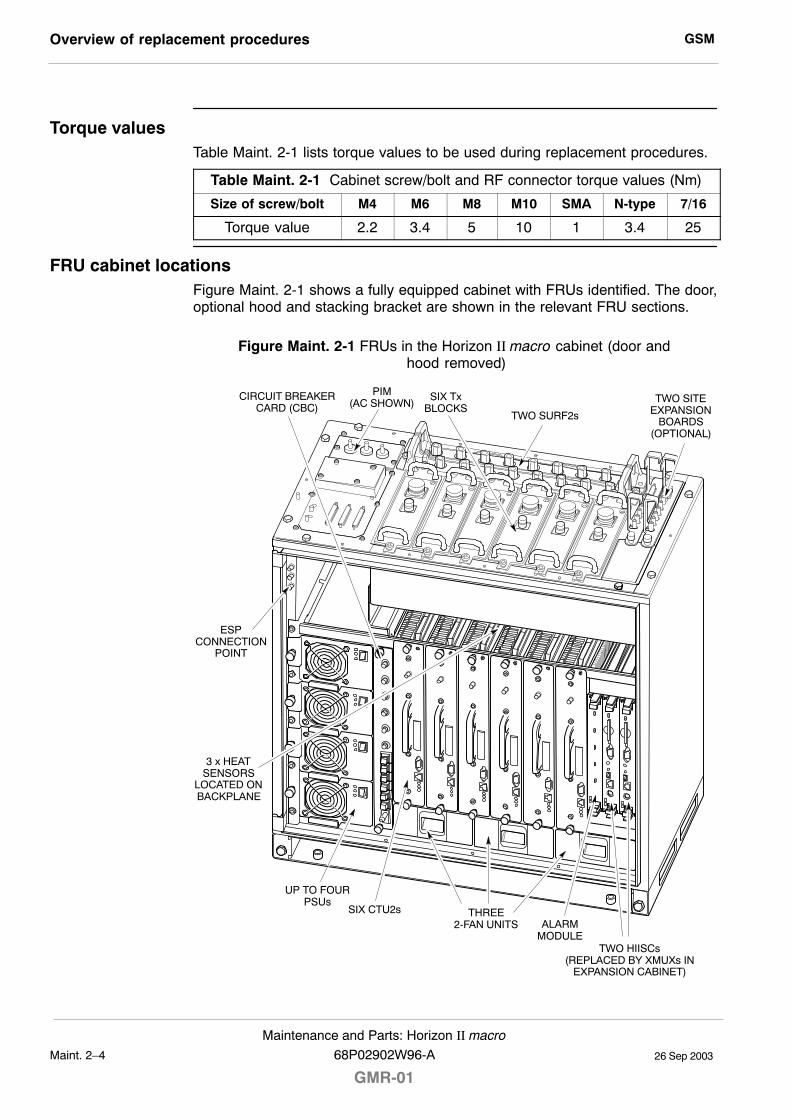
GSMOverview of replacement procedures
26 Sep 2003Maint. 2�4
Maintenance and Parts: Horizon II macro
GMR-0168P02902W96-A
Torque valuesTable Maint. 2-1 lists torque values to be used during replacement procedures.
Table Maint. 2-1 Cabinet screw/bolt and RF connector torque values (Nm)
Size of screw/bolt M4 M6 M8 M10 SMA N-type 7/16
Torque value 2.2 3.4 5 10 1 3.4 25
FRU cabinet locationsFigure Maint. 2-1 shows a fully equipped cabinet with FRUs identified. The door,optional hood and stacking bracket are shown in the relevant FRU sections.
Figure Maint. 2-1 FRUs in the Horizon II macro cabinet (door and hood removed)
CIRCUIT BREAKERCARD (CBC)
TWO HIISCs(REPLACED BY XMUXs IN
EXPANSION CABINET)
ALARMMODULE
THREE2-FAN UNITS
SIX CTU2s
SIX TxBLOCKS
TWO SURF2s
TWO SITEEXPANSION
BOARDS(OPTIONAL)
3 x HEATSENSORS
LOCATED ONBACKPLANE
UP TO FOURPSUs
ESPCONNECTION
POINT
PIM(AC SHOWN)
GSM Non-FRU components
26 Sep 2003
Maintenance and Parts: Horizon II macro
68P02902W96-A
GMR-01Maint. 2�5
Non-FRU components
Policy on non-FRU components
Non-FRU components are:
S Items unlikely to fail, but replacement of which is essential if failure occurs.
or
S Sub-components of FRUs, where local conditions may make it moreeconomical to repair the FRU.
CAUTION Only qualified personnel should attempt non-FRUcomponent replacement, in order to minimize risk ofequipment damage. For example, the CBIA main cagerequires care in removal and installation, and Individualfans require care in ensuring correct direction of airflow.
List of non-FRU components
Non-FRU components include the following:
S Door lock.
S Individual fans within a fan module.
S Any part of the CBIA: main cage, harness, interface panel, or backplane.
Procedure for replacing non-FRU components
Customers wanting to replace non-FRU components should:
1. Contact the local Motorola office for availability.
2. Seek Motorola advice for fitting non-FRU components.
CBIA attachment screws
The CBIA is attached to the cabinet by screws which should not be loosened:
S Seven M4 screws to the SURF2 harness (two guide pins lock cage intoposition).
S Five M6 (left side) and four M6 (right side) screws at the cabinet front.
S Eight M4 T20 screws for interface panel attachment to the top panel.
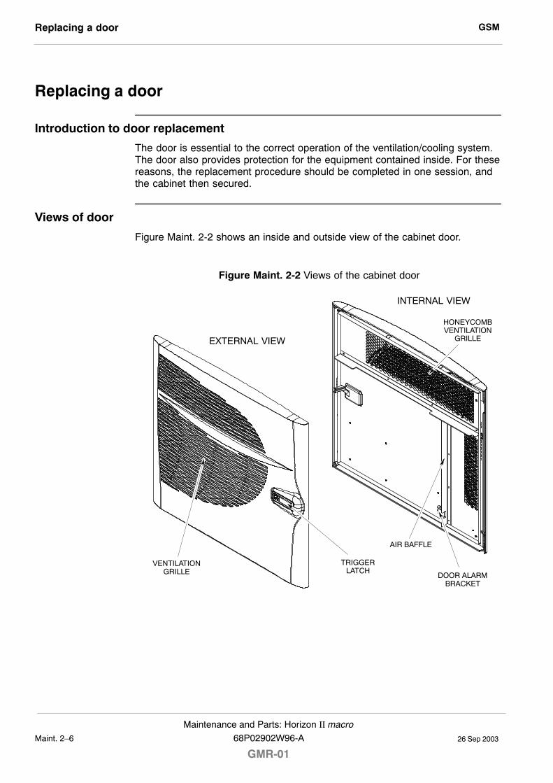
GSMReplacing a door
26 Sep 2003Maint. 2�6
Maintenance and Parts: Horizon II macro
GMR-0168P02902W96-A
Replacing a door
Introduction to door replacement
The door is essential to the correct operation of the ventilation/cooling system.The door also provides protection for the equipment contained inside. For thesereasons, the replacement procedure should be completed in one session, andthe cabinet then secured.
Views of door
Figure Maint. 2-2 shows an inside and outside view of the cabinet door.
Figure Maint. 2-2 Views of the cabinet door
VENTILATIONGRILLE
EXTERNAL VIEW
TRIGGERLATCH
INTERNAL VIEW
AIR BAFFLE
HONEYCOMBVENTILATION
GRILLE
DOOR ALARMBRACKET
GSM Replacing a door
26 Sep 2003
Maintenance and Parts: Horizon II macro
68P02902W96-A
GMR-01Maint. 2�7
Door replacement procedure
Removing a faulty door
To remove a door, open and:
1. On the cabinet, unscrew the M6 nut that secures the door earth cable tothe cabinet. Retain the nut for re-use.
2. Open the door to about 90° and then lift it off its hinges.
Fitting a replacement door
CAUTION Avoid damaging the honeycomb door vent.
To fit a replacement door:
1. Hold the door at about the 90° open position and lift onto the door hinges.
2. Attach the door earth cable to the cabinet using the M6 nut. Tighten to thecorrect torque (see Overview of replacement procedures).
3. Close the door and lock using the new key supplied with the door.
GSMReplacing a cabinet heat sensor
26 Sep 2003Maint. 2�8
Maintenance and Parts: Horizon II macro
GMR-0168P02902W96-A
Replacing a cabinet heat sensor
Overview of the heat sensors
The heat sensors plug into the backplane from the front, above the CTU2s.Each one can be removed separately, and a replacement inserted. CTU2 2 andCTU2 3 are removed to gain access for this procedure.
There is one 70 _C sensor and two 85 _C sensors. Each sensor is marked withthe appropriate temperature.
Heat sensor replacement procedure
To replace the heat sensors:
WARNING Before disconnecting RF cables, ensure that the RFpower is OFF by turning off the cabinet PSUs. Severeburns may result if RF power is ON when cables aredisconnected.
1. Remove CTU2 2 and CTU2 3 (see Replacing a CTU2) to access the heatsensors.
2. Identify the faulty heat sensor and unplug it from the backplane.
3. Insert the replacement heat sensor by pushing firmly into place.
4. Refit CTU2 2 and CTU2 3 (see Replacing a CTU2).
The heat sensors should now be operational.
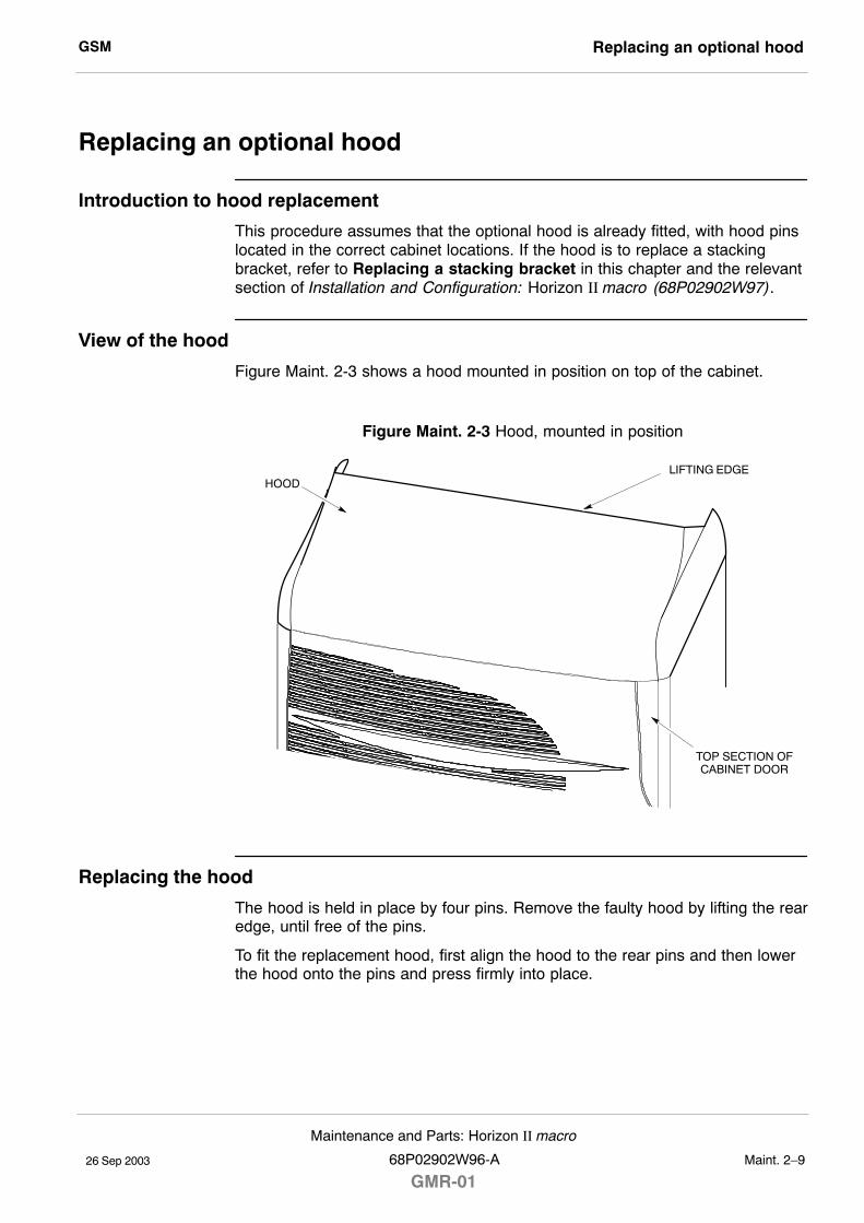
GSM Replacing an optional hood
26 Sep 2003
Maintenance and Parts: Horizon II macro
68P02902W96-A
GMR-01Maint. 2�9
Replacing an optional hood
Introduction to hood replacement
This procedure assumes that the optional hood is already fitted, with hood pinslocated in the correct cabinet locations. If the hood is to replace a stackingbracket, refer to Replacing a stacking bracket in this chapter and the relevantsection of Installation and Configuration: Horizon II macro (68P02902W97).
View of the hood
Figure Maint. 2-3 shows a hood mounted in position on top of the cabinet.
Figure Maint. 2-3 Hood, mounted in position
LIFTING EDGEHOOD
TOP SECTION OFCABINET DOOR
Replacing the hood
The hood is held in place by four pins. Remove the faulty hood by lifting the rearedge, until free of the pins.
To fit the replacement hood, first align the hood to the rear pins and then lowerthe hood onto the pins and press firmly into place.
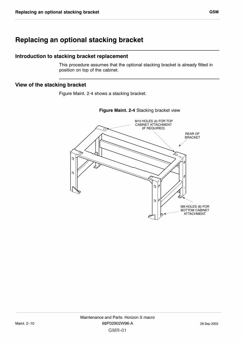
GSMReplacing an optional stacking bracket
26 Sep 2003Maint. 2�10
Maintenance and Parts: Horizon II macro
GMR-0168P02902W96-A
Replacing an optional stacking bracket
Introduction to stacking bracket replacement
This procedure assumes that the optional stacking bracket is already fitted inposition on top of the cabinet.
View of the stacking bracket
Figure Maint. 2-4 shows a stacking bracket.
Figure Maint. 2-4 Stacking bracket view
M8 HOLES (8) FORBOTTOM CABINET
ATTACHMENT.
M10 HOLES (4) FOR TOPCABINET ATTACHMENT
(IF REQUIRED)
REAR OFBRACKET
GSM Replacing an optional stacking bracket
26 Sep 2003
Maintenance and Parts: Horizon II macro
68P02902W96-A
GMR-01Maint. 2�11
Stacking bracket replacement procedure
Replace the stacking bracket as follows:
1. Remove the front cover by pulling it away from the stacking bracket.
2. If an upper cabinet is fitted on top of the stacking bracket, decommissionand remove this cabinet, as described in the relevant chapter ofInstallation and Configuration: Horizon II macro (68P02902W97).
3. Loosen and remove the eight M8 screws that secure the stacking bracketto the top of the cabinet.
WARNING The stacking bracket weighs 9.3 kg. Observe the correctlifting precautions.
4. Lift the stacking bracket off the cabinet.
5. Align the replacement stacking bracket onto the top of the cabinet, and fitthe eight M8 screws. Tighten to the correct torque (see Overview ofreplacement procedures).
6. If an upper cabinet was removed (step 2 above), install and re-commissionit (refer to Installation and Configuration: Horizon II macro(68P02902W97)).
7. Refit the front cover by attaching it to the side lugs and pushing it intoposition.
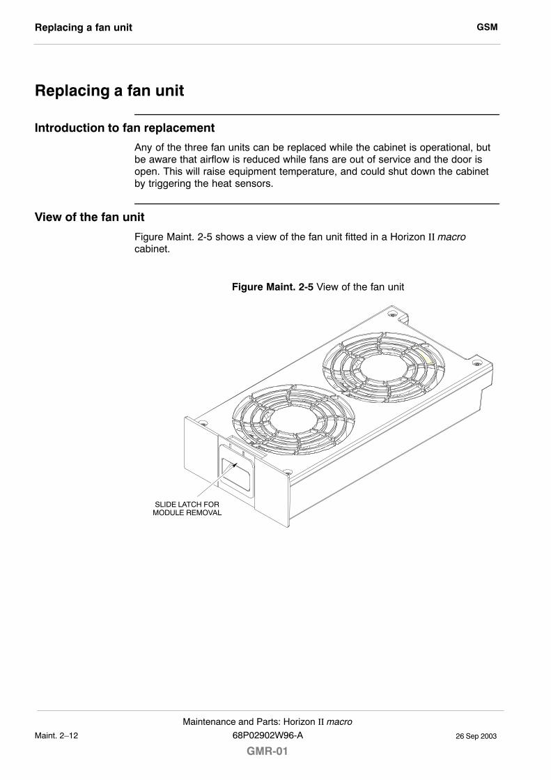
GSMReplacing a fan unit
26 Sep 2003Maint. 2�12
Maintenance and Parts: Horizon II macro
GMR-0168P02902W96-A
Replacing a fan unit
Introduction to fan replacement
Any of the three fan units can be replaced while the cabinet is operational, butbe aware that airflow is reduced while fans are out of service and the door isopen. This will raise equipment temperature, and could shut down the cabinetby triggering the heat sensors.
View of the fan unit
Figure Maint. 2-5 shows a view of the fan unit fitted in a Horizon II macrocabinet.
Figure Maint. 2-5 View of the fan unit
SLIDE LATCH FORMODULE REMOVAL
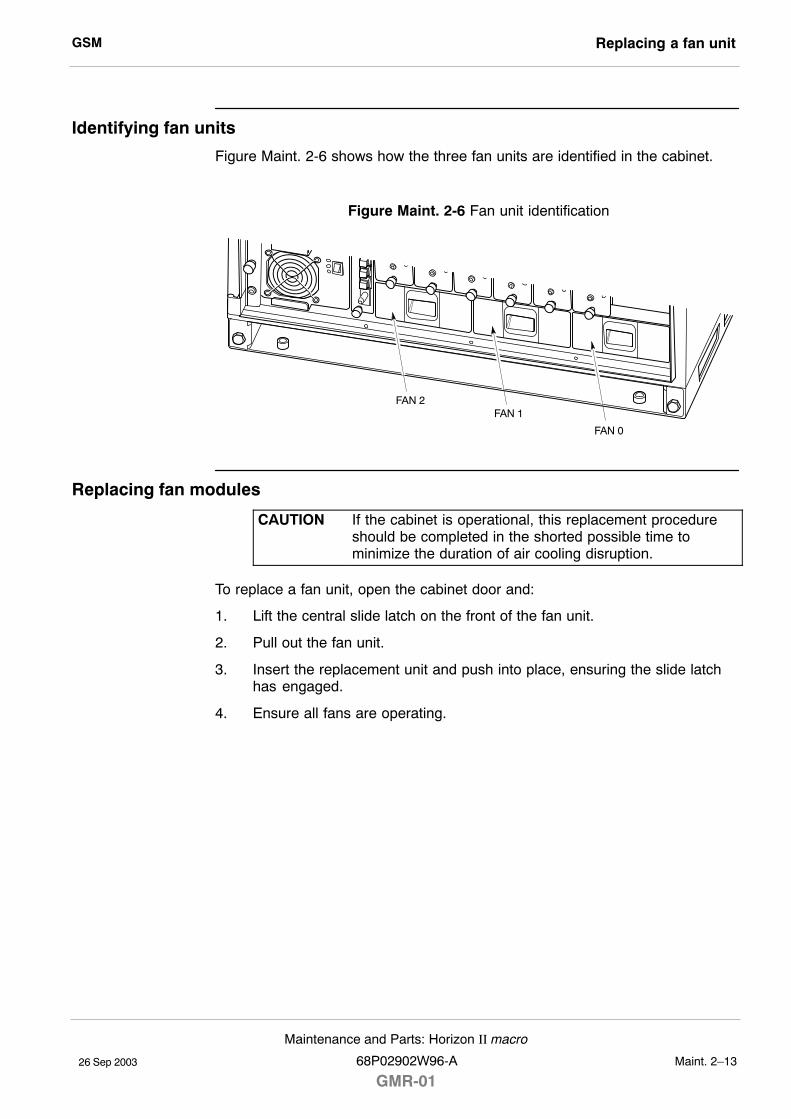
GSM Replacing a fan unit
26 Sep 2003
Maintenance and Parts: Horizon II macro
68P02902W96-A
GMR-01Maint. 2�13
Identifying fan units
Figure Maint. 2-6 shows how the three fan units are identified in the cabinet.
Figure Maint. 2-6 Fan unit identification
FAN 2FAN 1
FAN 0
Replacing fan modules
CAUTION If the cabinet is operational, this replacement procedureshould be completed in the shorted possible time tominimize the duration of air cooling disruption.
To replace a fan unit, open the cabinet door and:
1. Lift the central slide latch on the front of the fan unit.
2. Pull out the fan unit.
3. Insert the replacement unit and push into place, ensuring the slide latchhas engaged.
4. Ensure all fans are operating.
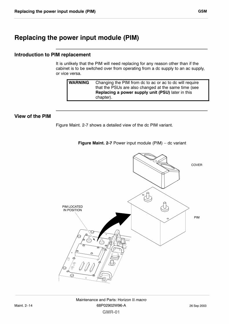
GSMReplacing the power input module (PIM)
26 Sep 2003Maint. 2�14
Maintenance and Parts: Horizon II macro
GMR-0168P02902W96-A
Replacing the power input module (PIM)
Introduction to PIM replacement
It is unlikely that the PIM will need replacing for any reason other than if thecabinet is to be switched over from operating from a dc supply to an ac supply,or vice versa.
WARNING Changing the PIM from dc to ac or ac to dc will requirethat the PSUs are also changed at the same time (seeReplacing a power supply unit (PSU) later in thischapter).
View of the PIM
Figure Maint. 2-7 shows a detailed view of the dc PIM variant.
Figure Maint. 2-7 Power input module (PIM) � dc variant
COVER
PIM
PIM LOCATEDIN POSITION
GSM Replacing the power input module (PIM)
26 Sep 2003
Maintenance and Parts: Horizon II macro
68P02902W96-A
GMR-01Maint. 2�15
Replacing the PIM
The procedure for replacing the PIM is basically the same for both types,regardless of whether the existing and replacement PIM is dc or ac.
To replace the PIM:
1. Verify that the power source isolator is switched to OFF and locked (ifpossible).
2. Remove the cover to expose the power terminals.
3. Undo the M6 nuts and remove the cables from the terminals. If changingthe PIM from dc to ac or vice versa, completely remove the cables fromthe cable run and lay the cables from the new power source to thecabinet.
4. Undo the two M4 captive screws that secure the PIM in position and thenlift the PIM out of its housing.
5. Insert the new PIM into its housing and push fully home to ensure that theconnector on its base mates with the connector in the bottom of thehousing. Fit and tighten the two M4 Torx screws to the correct torque.
6. If new power cables are being used (in cases when the PIM is beingchanged from dc to ac or vice versa), fit the cone shaped protectivecovers onto the power cables and then connect the cables to the terminalson the new PIM. Tighten the M6 terminal nuts to the correct torque.
7. Refit the power terminal cover.
8. If the PIM has been changed from dc to ac or vice versa, replace thePSUs with those of the appropriate type (described later in this chapter).
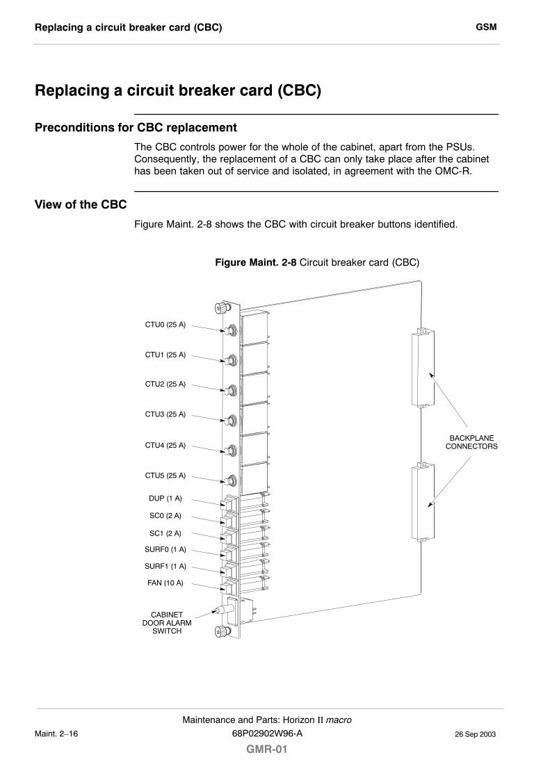
GSMReplacing a circuit breaker card (CBC)
26 Sep 2003Maint. 2�16
Maintenance and Parts: Horizon II macro
GMR-0168P02902W96-A
Replacing a circuit breaker card (CBC)
Preconditions for CBC replacement
The CBC controls power for the whole of the cabinet, apart from the PSUs.Consequently, the replacement of a CBC can only take place after the cabinethas been taken out of service and isolated, in agreement with the OMC-R.
View of the CBC
Figure Maint. 2-8 shows the CBC with circuit breaker buttons identified.
Figure Maint. 2-8 Circuit breaker card (CBC)
BACKPLANECONNECTORS
CTU0 (25 A)
CTU1 (25 A)
CTU2 (25 A)
CTU3 (25 A)
CTU4 (25 A)
CTU5 (25 A)
SC0 (2 A)
SC1 (2 A)
SURF0 (1 A)
SURF1 (1 A)
DUP (1 A)
FAN (10 A)
CABINETDOOR ALARM
SWITCH
GSM Replacing a circuit breaker card (CBC)
26 Sep 2003
Maintenance and Parts: Horizon II macro
68P02902W96-A
GMR-01Maint. 2�17
Replacing the CBC
To replace the CBC:
1. Verify that the power source isolator is switched to OFF, and locked (ifpossible).
2. Set the switch of each PSU to the OUTPUT DISABLE position.
3. Unscrew both CBC module attachment screws using a T20 Torx driver.
4. Pull the CBC out of its slot in the cabinet.
5. Ensure that all circuit breaker buttons on the new CBC are set to the out(off) position.
6. Slide the replacement CBC into its slot and press firmly into place.
7. Tighten both module attachment screws to the correct torque (seeOverview of replacement procedures), using a T20 Torx driver.
To restore power to the cabinet:
1. Switch on the external power supply to the cabinet.
2. Set each PSU switch to the OUTPUT ENABLE position. Check that theACTIVE (green) LED is on and the ALARM (red) LED is off on each PSU.
3. Switch on the equipment in the cabinet by pressing the CBC isolatorpush-buttons in the following sequence:
� FAN. Check that each fan (six in total) is operating correctly.
� SC0, and SC1 if fitted (or XMUX(s) if a slave cabinet).Check that the appropriate HIISC/XMUX indicators operate correctly.
� SURF0 (and SURF1, if fitted).
� DUP.
� CTU0 to CTUn (where n = 1 to 5, depending on the number ofCTU2s installed).Check that the front panel LEDs for each CTU2 indicate correctoperation.
4. Close the door to ensure correct ventilation.
This completes the CBC replacement procedure and power up sequence for acabinet.

GSMReplacing a power supply unit (PSU)
26 Sep 2003Maint. 2�18
Maintenance and Parts: Horizon II macro
GMR-0168P02902W96-A
Replacing a power supply unit (PSU)
Introduction to PSU replacementThere are four slots for PSUs in the cabinet. Three PSUs are required to powera fully equipped cabinet. The fourth slot can be used for an additional powersupply to provide redundancy. A replacement PSU can be inserted into anavailable slot without powering down, thereby avoiding any need to take thecabinet out of service.
Preconditions for PSU replacementThe replacement PSU must be of the correct type for the cabinet (+ 27 V dc,�48/60 V dc, or 120/240 V ac).
CAUTION The replacement PSU must have the correct input voltagerating for the cabinet.
View of the PSUFigure Maint. 2-9 shows a view of the PSU with key features identified.
Figure Maint. 2-9 PSU, with key features identified
M4 MODULEATTACHMENT
SCREW
GREEN LED(ACTIVE)
OUTPUTDISABLE SWITCH
AIRVENT
RED LED(ALARM)
HANDLE
NOTE There are several manufacturers of the PSUs. All PSUs ofthe same type are fully compatible with each other,regardless of manufacturer.
GSM Replacing a power supply unit (PSU)
26 Sep 2003
Maintenance and Parts: Horizon II macro
68P02902W96-A
GMR-01Maint. 2�19
Replacing a non-redundant PSU
Use this procedure if there are two or three PSUs installed in the cabinet. Toreplace a non-redundant PSU:
1. Set the switch of the replacement PSU to OUTPUT DISABLE.
2. Remove the blanking plate of the spare slot (if fitted) by unscrewing theretaining screw with a Torx driver.
3. Insert the replacement PSU in the resulting available slot. Push the PSUall the way in and secure in position by tightening the M4 retaining screwto the correct torque using a Torx driver.
4. Set the output switch to OUTPUT ENABLE. Check that the ACTIVE LED(green) illuminates.
5. Set the output switch of the faulty PSU to OUTPUT DISABLE. TheACTIVE LED will extinguish (the ACTIVE LED may already be off if a faulthas resulted in output failure of that PSU). The ALARM LED (red) willilluminate, or will stay on if already lit due to alarm state.
6. Undo the M4 retaining screw on the front of the faulty PSU module andpull the module out of the cabinet using the handle. The ALARM LED willextinguish.
7. If required, fit the cover plate in the vacated PSU position and tighten theretaining screw to the correct torque using a Torx driver.
Replacing a redundant PSU
Use this procedure if there are four PSUs fitted. To replace a redundant PSU:
1. Set the switch on the replacement PSU to OUTPUT DISABLE.
2. Set the switch of the faulty PSU to OUTPUT DISABLE. The ACTIVE LEDwill extinguish (the ACTIVE LED may already be off if a fault has resultedin output failure of that PSU). The ALARM LED (red) will illuminate, or willstay on if already lit due to alarm state.
3. Undo the M4 retaining screw on the front of the faulty PSU module andpull the module out of the cabinet using the handle. The ALARM LED willextinguish.
4. Insert the replacement PSU in the empty slot. Push the PSU all the way inand secure in position by tightening the M4 retaining screw to the correcttorque using a Torx driver.
5. Set the front panel switch to OUTPUT ENABLE. Check that the ACTIVELED is lit.
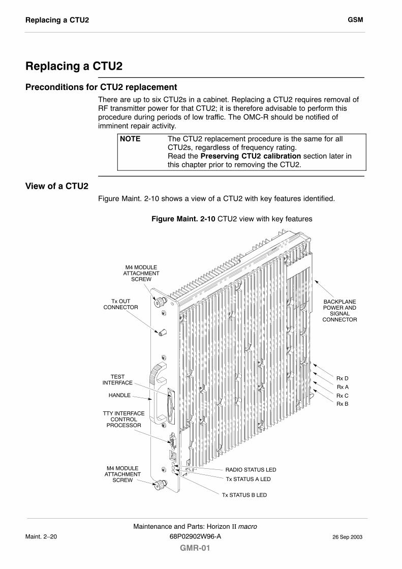
GSMReplacing a CTU2
26 Sep 2003Maint. 2�20
Maintenance and Parts: Horizon II macro
GMR-0168P02902W96-A
Replacing a CTU2
Preconditions for CTU2 replacementThere are up to six CTU2s in a cabinet. Replacing a CTU2 requires removal ofRF transmitter power for that CTU2; it is therefore advisable to perform thisprocedure during periods of low traffic. The OMC-R should be notified ofimminent repair activity.
NOTE The CTU2 replacement procedure is the same for allCTU2s, regardless of frequency rating.Read the Preserving CTU2 calibration section later inthis chapter prior to removing the CTU2.
View of a CTU2Figure Maint. 2-10 shows a view of a CTU2 with key features identified.
Figure Maint. 2-10 CTU2 view with key features
Tx OUTCONNECTOR
Tx STATUS A LED
HANDLE
M4 MODULEATTACHMENT
SCREW
M4 MODULEATTACHMENT
SCREW
TTY INTERFACECONTROL
PROCESSOR
TESTINTERFACE
RADIO STATUS LED
Rx D
Rx A
BACKPLANEPOWER AND
SIGNALCONNECTOR
Rx C
Rx B
Tx STATUS B LED
GSM Replacing a CTU2
26 Sep 2003
Maintenance and Parts: Horizon II macro
68P02902W96-A
GMR-01Maint. 2�21
CTU2 replacement procedure
CAUTION An earthing wrist strap must be worn when handlingCTU2s. An ESP earthing connection point is provided onthe top left at the front of the cabinet (refer toFigure Maint. 2-1).
Removing a faulty CTU2
NOTE Ensure that the preserve CTU2 calibration data feature isenabled and determine which calibration data exchangescenario applies before proceeding further (refer toEnabling the preserve CTU2 calibration data featureand Table Maint. 2-2 respectively, later in this chapter).
To remove a CTU2:
1. Locate the CTU2 to be replaced. CTU2s are sequentially numbered, withCTU2 0 on the right, and CTU2 5 on the left.
2. Disable the CTU2 transmit RF power by using the lock_device orshutdown_device command at the OMC-R or from a PC connected tothe HIISC.
NOTE Refer to Technical Description: BSS Command Reference(68P02901W23) for information on usage and specificcommands.
3. When the CTU2 has been shutdown, check that the yellow Tx STATUSLEDs are unlit.
4. Press and release the appropriate CTU2 circuit breaker button on the CBCto the out (off) position. Ensure the RADIO STATUS LED is unlit.
WARNING Ensure that RF power is OFF, before disconnecting RFcables. Severe burns may result if RF power is ON whencables are disconnected.
5. Unscrew the coaxial cable from the Tx OUT SMA connector at the top ofthe CTU2 front panel.
6. Unscrew the two CTU2 attachment screws using a T20 Torx driver.
WARNING The CTU2 weighs 5 kg. Handle with care.
CAUTION Take care to avoid damaging the CTU2 rear connectorswhen handling outside of the cabinet.
7. Withdraw the CTU2 using the handle. Support the unit from underneath asit slides out.
GSMReplacing a CTU2
26 Sep 2003Maint. 2�22
Maintenance and Parts: Horizon II macro
GMR-0168P02902W96-A
Fitting a replacement CTU2
To fit a replacement CTU2:
1. Ensure that the correct CTU2 circuit breaker push-button on the CBC hasbeen pressed to the out (off) position.
2. Ensure that the transmit RF power of the correct CTU2 has been lockedusing the lock_device or shutdown_device command at the OMC-Ror from a PC connected to the HIISC.
3. Insert the replacement CTU2 module, taking care to locate the module onthe guide rails. Push firmly into place.
4. Tighten both module attachment screws to the correct torque (seeOverview of replacement procedures), using a T20 Torx driver.
NOTE The Tx cable has a 90° SMA connector at one end, and astraight SMA connector at the other end. The 90° end isdesigned for connection to the Tx port of the CTU2.
5. Screw the 90° SMA connector of the coaxial cable onto the Tx OUT SMAconnector at the top of the CTU2 front panel. Tighten to the correct torque(see Overview of replacement procedures).
6. Press and release the appropriate CTU2 circuit breaker push-button onthe CBC. The RADIO STATUS LED will flash green for about two minutes,and then remain lit.
CAUTION If the RADIO STATUS LED is flashing green or alternatingred and green, boot code is downloading or flashreprogramming is taking place. Do not remove power orreset the cabinet until downloading has been completedas this will corrupt the non-volatile memory.If the boot code is corrupted, contact Motorola CustomerNetwork Resolution Centre requesting the boot coderestoration procedure and the appropriate boot code file.
7. Enable the CTU2 transmit RF power by using the unlock_device orins_device command at the OMC-R or from a PC connected to theHIISC. The appropriate Tx STATUS LED (yellow) will be lit if the CTU2 istransmitting.
8. Calibrate the CTU2 using the appropriate procedure, as described inCTU2 calibration data exchange procedures later in this chapter.
9. Notify the OMC-R of base station availability and log the maintenanceactivity.
GSM Preserving CTU2 calibration
26 Sep 2003
Maintenance and Parts: Horizon II macro
68P02902W96-A
GMR-01Maint. 2�23
Preserving CTU2 calibrationNOTE Although the preserve calibration data feature described
here refers specifically to the CTU2, calibration data canbe tranferred between the CTU used in Horizonmacro andthe CTU2 using the same procedure.
Introduction to preserving CTU2 calibration
This section describes the preserve CTU2 transceiver calibration feature, whichuses commands to store, display and clear calibration data. This feature is usedon busy systems where there is a need to replace a CTU2 quickly and thusreduce system down time during peak hours.
NOTE After the CTU2 has been replaced, it will be necessary torevisit the site at an off-peak period to carry out bay leveland cell site power (CSPWR) calibration to fully optimizethe hardware. The bay level calibration procedure isdescribed later in this chapter. The CSPWR calibrationprocedure is described in Chapter 3 of this category.
Calibration data overview
This function enables malfunctioning CTU2s to be replaced without the need toremove the cell from service. The calibration offsets can be displayed andcleared using the disp_cal_data and clear_cal_data commands.
Display calibration offsets data
The disp_cal_data command only displays offsets from the CTU2 if the DRI isin the busy-unlocked (B-U) state. The GPROC CM database values aredisplayed when the CTU2 is locked or not busy. If the calibration values havebeen cleared, they will not be available on the specific RAM of the CTU2 or theCM database, and the response will be NO CALIBRATION DATA AVAILABLE.
GSMPreserving CTU2 calibration
26 Sep 2003Maint. 2�24
Maintenance and Parts: Horizon II macro
GMR-0168P02902W96-A
Store calibration data
The store_cal_data command sets a flag to indicate that when the CTU2 isunlocked and comes into service, the calibration values will be copied from theRAM in the CTU2 into the GPROC CM database. The values from the RAM inthe CTU2 will only be copied to the database if there are no calibration values inthe GPROC CM database, and if the CTU2 has values in the RAM to be copied.
If the RAM in the CTU2 has been cleared of all values, and the GPROC CMdatabase has calibration values for that specific CTU2, when the CTU2 isunlocked it will get a copy of these values from the CM database. Differentcalibration values for the same CTU2 can exist in the CM database and theRAM in the CTU2.
Care has to be taken when calibrating a CTU2. To ensure that the values in theRAM of the CTU2 and CM database have the same calibration data, theexisting values have to be cleared using the clear_cal_data command before acalibration can be successful and the correct calibration data saved. Calibrationdata is stored in the master CM database at the BSC, and is used to update theCM database copy at the BTS if it is valid.
NOTE The value 0800H must be cleared from all the paths(columns of data) stored in the CTU2, otherwise thecalibration data will not be uploaded to the CM database.
Clear calibration data
The clear_cal_data command removes the offsets from RAM and thedatabase. To clear the data from a CTU2 that is B-U in the network, thecommand is issued after the CTU2 is locked. A new CTU2 being put into thenetwork must first be allowed to become B-U and then locked, only after this willthe command clear the calibration data for that CTU2. This is explained in thecalibration procedure.
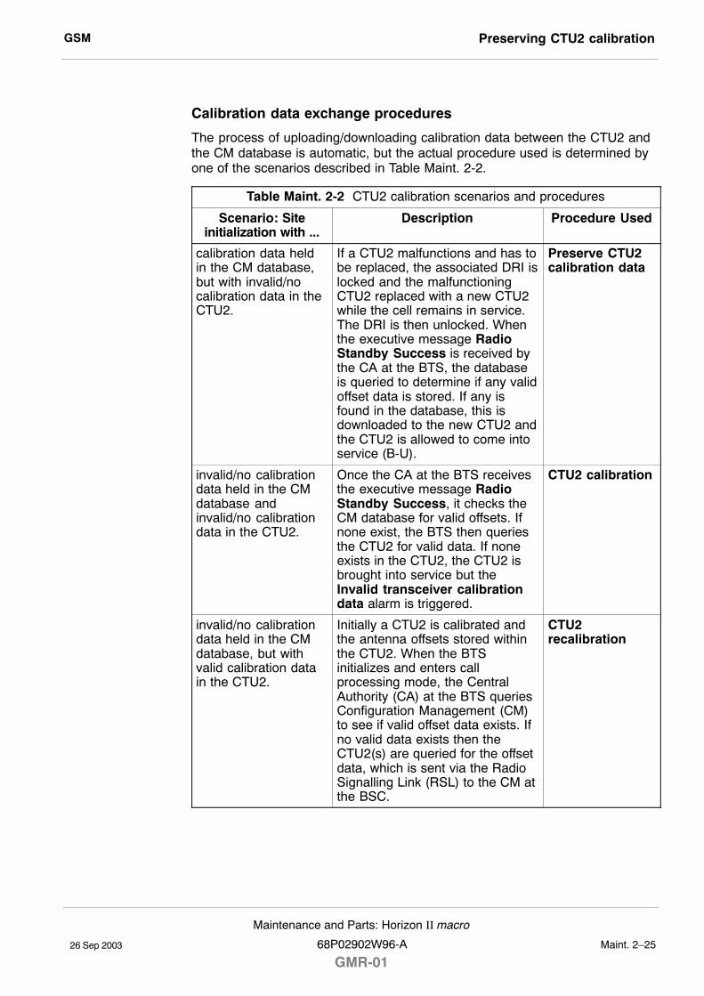
GSM Preserving CTU2 calibration
26 Sep 2003
Maintenance and Parts: Horizon II macro
68P02902W96-A
GMR-01Maint. 2�25
Calibration data exchange procedures
The process of uploading/downloading calibration data between the CTU2 andthe CM database is automatic, but the actual procedure used is determined byone of the scenarios described in Table Maint. 2-2.
Table Maint. 2-2 CTU2 calibration scenarios and procedures
Scenario: Siteinitialization with ...
Description Procedure Used
calibration data heldin the CM database,but with invalid/nocalibration data in theCTU2.
If a CTU2 malfunctions and has tobe replaced, the associated DRI islocked and the malfunctioningCTU2 replaced with a new CTU2while the cell remains in service.The DRI is then unlocked. Whenthe executive message RadioStandby Success is received bythe CA at the BTS, the databaseis queried to determine if any validoffset data is stored. If any isfound in the database, this isdownloaded to the new CTU2 andthe CTU2 is allowed to come intoservice (B-U).
Preserve CTU2calibration data
invalid/no calibrationdata held in the CMdatabase andinvalid/no calibrationdata in the CTU2.
Once the CA at the BTS receivesthe executive message RadioStandby Success, it checks theCM database for valid offsets. Ifnone exist, the BTS then queriesthe CTU2 for valid data. If noneexists in the CTU2, the CTU2 isbrought into service but theInvalid transceiver calibrationdata alarm is triggered.
CTU2 calibration
invalid/no calibrationdata held in the CMdatabase, but withvalid calibration datain the CTU2.
Initially a CTU2 is calibrated andthe antenna offsets stored withinthe CTU2. When the BTSinitializes and enters callprocessing mode, the CentralAuthority (CA) at the BTS queriesConfiguration Management (CM)to see if valid offset data exists. Ifno valid data exists then theCTU2(s) are queried for the offsetdata, which is sent via the RadioSignalling Link (RSL) to the CM atthe BSC.
CTU2recalibration
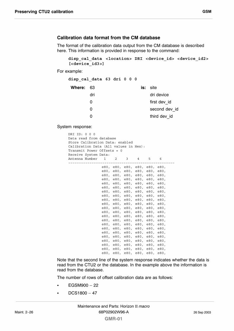
GSMPreserving CTU2 calibration
26 Sep 2003Maint. 2�26
Maintenance and Parts: Horizon II macro
GMR-0168P02902W96-A
Calibration data format from the CM database
The format of the calibration data output from the CM database is describedhere. This information is provided in response to the command:
disp_cal_data <location> DRI <device_id> <device_id2>[<device_id3>]
For example:
disp_cal_data 63 dri 0 0 0
Where: 63 is: site
dri dri device
0 first dev_id
0 second dev_id
0 third dev_id
System response:
DRI ID: 0 0 0Data read from databaseStore Calibration Data: enabledCalibration Data (All values in Hex):Transmit Power Offsets = 0Receive System Data:Antenna Number 1 2 3 4 5 6––––––––––––––––––––––––––––––––––––––––––––––––––
e80, e80, e80, e80, e80, e80,e80, e80, e80, e80, e80, e80,e80, e80, e80, e80, e80, e80,e80, e80, e80, e80, e80, e80,e80, e80, e80, e80, e80, e80,e80, e80, e80, e80, e80, e80,e80, e80, e80, e80, e80, e80,e80, e80, e80, e80, e80, e80,e80, e80, e80, e80, e80, e80,e80, e80, e80, e80, e80, e80,e80, e80, e80, e80, e80, e80,e80, e80, e80, e80, e80, e80,e80, e80, e80, e80, e80, e80,e80, e80, e80, e80, e80, e80,e80, e80, e80, e80, e80, e80,e80, e80, e80, e80, e80, e80,e80, e80, e80, e80, e80, e80,e80, e80, e80, e80, e80, e80,e80, e80, e80, e80, e80, e80,e80, e80, e80, e80, e80, e80,e80, e80, e80, e80, e80, e80,e80, e80, e80, e80, e80, e80,
Note that the second line of the system response indicates whether the data isread from the CTU2 or the database. In the example above the information isread from the database.
The number of rows of offset calibration data are as follows:
S EGSM900 � 22
S DCS1800 � 47
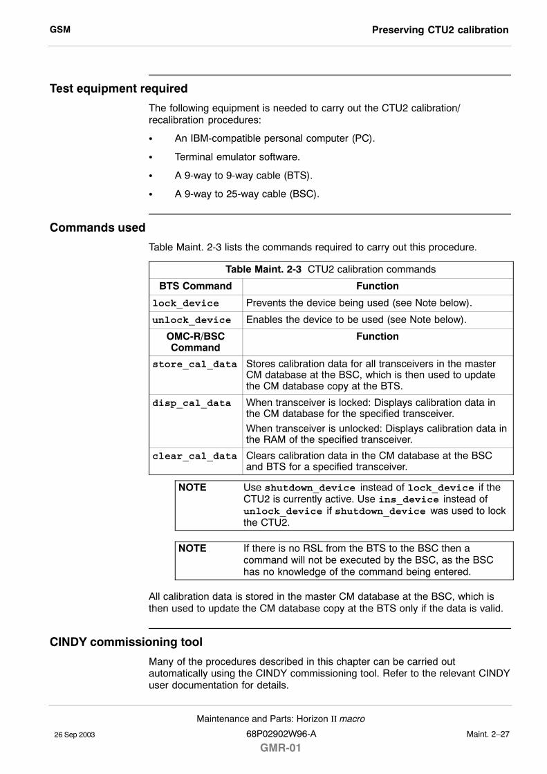
GSM Preserving CTU2 calibration
26 Sep 2003
Maintenance and Parts: Horizon II macro
68P02902W96-A
GMR-01Maint. 2�27
Test equipment required
The following equipment is needed to carry out the CTU2 calibration/recalibration procedures:
S An IBM-compatible personal computer (PC).
S Terminal emulator software.
S A 9-way to 9-way cable (BTS).
S A 9-way to 25-way cable (BSC).
Commands used
Table Maint. 2-3 lists the commands required to carry out this procedure.
Table Maint. 2-3 CTU2 calibration commands
BTS Command Function
lock_device Prevents the device being used (see Note below).
unlock_device Enables the device to be used (see Note below).
OMC-R/BSCCommand
Function
store_cal_data Stores calibration data for all transceivers in the masterCM database at the BSC, which is then used to updatethe CM database copy at the BTS.
disp_cal_data When transceiver is locked: Displays calibration data inthe CM database for the specified transceiver.
When transceiver is unlocked: Displays calibration data inthe RAM of the specified transceiver.
clear_cal_data Clears calibration data in the CM database at the BSCand BTS for a specified transceiver.
NOTE Use shutdown_device instead of lock_device if theCTU2 is currently active. Use ins_device instead ofunlock_device if shutdown_device was used to lockthe CTU2.
NOTE If there is no RSL from the BTS to the BSC then acommand will not be executed by the BSC, as the BSChas no knowledge of the command being entered.
All calibration data is stored in the master CM database at the BSC, which isthen used to update the CM database copy at the BTS only if the data is valid.
CINDY commissioning tool
Many of the procedures described in this chapter can be carried outautomatically using the CINDY commissioning tool. Refer to the relevant CINDYuser documentation for details.
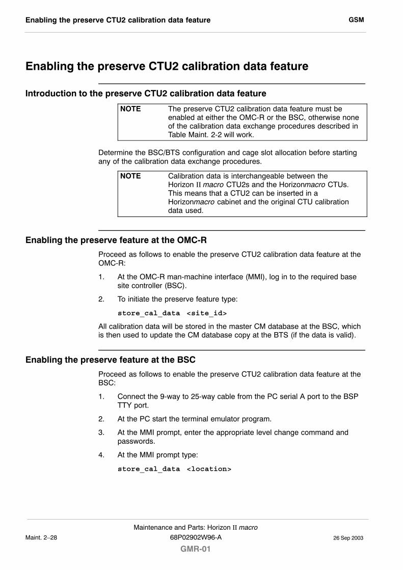
GSMEnabling the preserve CTU2 calibration data feature
26 Sep 2003Maint. 2�28
Maintenance and Parts: Horizon II macro
GMR-0168P02902W96-A
Enabling the preserve CTU2 calibration data feature
Introduction to the preserve CTU2 calibration data feature
NOTE The preserve CTU2 calibration data feature must beenabled at either the OMC-R or the BSC, otherwise noneof the calibration data exchange procedures described inTable Maint. 2-2 will work.
Determine the BSC/BTS configuration and cage slot allocation before startingany of the calibration data exchange procedures.
NOTE Calibration data is interchangeable between theHorizon II macro CTU2s and the Horizonmacro CTUs.This means that a CTU2 can be inserted in aHorizonmacro cabinet and the original CTU calibrationdata used.
Enabling the preserve feature at the OMC-R
Proceed as follows to enable the preserve CTU2 calibration data feature at theOMC-R:
1. At the OMC-R man-machine interface (MMI), log in to the required basesite controller (BSC).
2. To initiate the preserve feature type:
store_cal_data <site_id>
All calibration data will be stored in the master CM database at the BSC, whichis then used to update the CM database copy at the BTS (if the data is valid).
Enabling the preserve feature at the BSC
Proceed as follows to enable the preserve CTU2 calibration data feature at theBSC:
1. Connect the 9-way to 25-way cable from the PC serial A port to the BSPTTY port.
2. At the PC start the terminal emulator program.
3. At the MMI prompt, enter the appropriate level change command andpasswords.
4. At the MMI prompt type:
store_cal_data <location>
GSM CTU2 calibration data exchange procedures
26 Sep 2003
Maintenance and Parts: Horizon II macro
68P02902W96-A
GMR-01Maint. 2�29
CTU2 calibration data exchange procedures
Introduction to CTU2 calibration data exchange procedures
The procedures listed in Table Maint. 2-2 are described here in detail. All threeprocedures assume that the preserve CTU2 calibration data feature (describedpreviously) has been enabled.
Preserve CTU2 calibration data procedure
NOTE This procedure assumes that the store_cal_data command has been used on the CTU2 at some timepreviously while it was operational.
To replace a CTU2 using preserved calibration data, follow the procedures forCTU2 replacement given previously in CTU2 replacement procedure.
The calibration data stored in the CM database is downloaded into the RAM ofthe new CTU2. The data is also stored in the non-volatile CTU2 memory.
NOTE After the CTU2 has been replaced, it will still be necessaryto revisit the site at an off-peak hour, to carry out bay leveland CSPWR calibration to fully optimize the hardware.
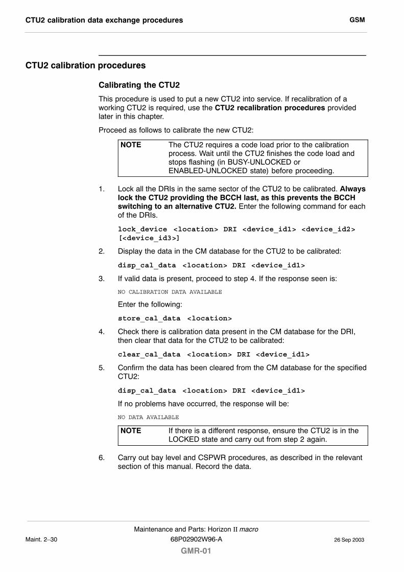
GSMCTU2 calibration data exchange procedures
26 Sep 2003Maint. 2�30
Maintenance and Parts: Horizon II macro
GMR-0168P02902W96-A
CTU2 calibration procedures
Calibrating the CTU2
This procedure is used to put a new CTU2 into service. If recalibration of aworking CTU2 is required, use the CTU2 recalibration procedures providedlater in this chapter.
Proceed as follows to calibrate the new CTU2:
NOTE The CTU2 requires a code load prior to the calibrationprocess. Wait until the CTU2 finishes the code load andstops flashing (in BUSY-UNLOCKED orENABLED-UNLOCKED state) before proceeding.
1. Lock all the DRIs in the same sector of the CTU2 to be calibrated. Alwayslock the CTU2 providing the BCCH last, as this prevents the BCCHswitching to an alternative CTU2. Enter the following command for eachof the DRIs.
lock_device <location> DRI <device_id1> <device_id2>[<device_id3>]
2. Display the data in the CM database for the CTU2 to be calibrated:
disp_cal_data <location> DRI <device_id1>
3. If valid data is present, proceed to step 4. If the response seen is:
NO CALIBRATION DATA AVAILABLE
Enter the following:
store_cal_data <location>
4. Check there is calibration data present in the CM database for the DRI,then clear that data for the CTU2 to be calibrated:
clear_cal_data <location> DRI <device_id1>
5. Confirm the data has been cleared from the CM database for the specifiedCTU2:
disp_cal_data <location> DRI <device_id1>
If no problems have occurred, the response will be:
NO DATA AVAILABLE
NOTE If there is a different response, ensure the CTU2 is in theLOCKED state and carry out from step 2 again.
6. Carry out bay level and CSPWR procedures, as described in the relevantsection of this manual. Record the data.

GSM CTU2 calibration data exchange procedures
26 Sep 2003
Maintenance and Parts: Horizon II macro
68P02902W96-A
GMR-01Maint. 2�31
Checking the CTU2 calibration
Proceed as follows to check the CTU2 calibration:
1. Unlock the DRI of the calibrated CTU2.
NOTE Ensure the previous calibration data has been clearedbefore unlocking the CTU2.
Enter the command:
unlock_device <location> DRI <device_id1>
Check that the calibrated CTU2 passes into BUSY-UNLOCKED state. Thenew calibration data is uploaded to the CM database and is then used toupdate the copy at the BTS.
2. Check the calibration data of the DRI of the calibrated CTU2 against thevalues noted in step 6 of the previous procedure.
NOTE Allow one minute after uploading for the values in the CMdatabase at the BSC to be updated.
Enter the command:
disp_cal_data <location> DRI <device_id1>
The values seen should match the previous ones.
NOTE If the CTU2 is BUSY-UNLOCKED the data can be readdirectly from the CTU2. In ENABLED-UNLOCKED orLOCKED state calibration data is read from the CMdatabase.
3. Make test calls in all timeslots of the new DRI to check audio quality andthen lock the tested DRI using the command:
lock_device <location> DRI <device_id1>
4. With the CTU2 LOCKED (or in ENABLED-UNLOCKED state), ensure thecalibration process has been carried out correctly by checking that the CMdatabase at the BSC has been updated with the new values.
Enter the command:
disp_cal_data <location> DRI <device_id1>
The values seen should match the previous ones.
5. If everything is in order, the cell can be put back into service. Unlock all theDRIs in the same sector that were locked previously using the command:
unlock_device <location> DRI <device_id1> <device_id2>[<device_id3>]
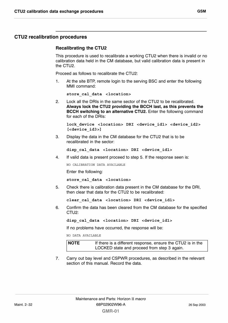
GSMCTU2 calibration data exchange procedures
26 Sep 2003Maint. 2�32
Maintenance and Parts: Horizon II macro
GMR-0168P02902W96-A
CTU2 recalibration procedures
Recalibrating the CTU2
This procedure is used to recalibrate a working CTU2 when there is invalid or nocalibration data held in the CM database, but valid calibration data is present inthe CTU2.
Proceed as follows to recalibrate the CTU2:
1. At the site BTP, remote login to the serving BSC and enter the followingMMI command:
store_cal_data <location>
2. Lock all the DRIs in the same sector of the CTU2 to be recalibrated.Always lock the CTU2 providing the BCCH last, as this prevents theBCCH switching to an alternative CTU2. Enter the following commandfor each of the DRIs:
lock_device <location> DRI <device_id1> <device_id2>[<device_id3>]
3. Display the data in the CM database for the CTU2 that is to berecalibrated in the sector:
disp_cal_data <location> DRI <device_id1>
4. If valid data is present proceed to step 5. If the response seen is:
NO CALIBRATION DATA AVAILABLE
Enter the following:
store_cal_data <location>
5. Check there is calibration data present in the CM database for the DRI,then clear that data for the CTU2 to be recalibrated:
clear_cal_data <location> DRI <device_id1>
6. Confirm the data has been cleared from the CM database for the specifiedCTU2:
disp_cal_data <location> DRI <device_id1>
If no problems have occurred, the response will be:
NO DATA AVAILABLE
NOTE If there is a different response, ensure the CTU2 is in theLOCKED state and proceed from step 3 again.
7. Carry out bay level and CSPWR procedures, as described in the relevantsection of this manual. Record the data.
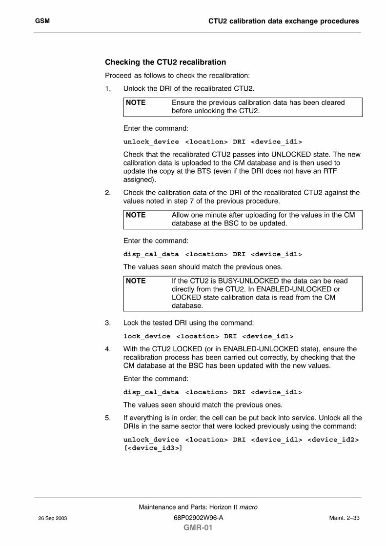
GSM CTU2 calibration data exchange procedures
26 Sep 2003
Maintenance and Parts: Horizon II macro
68P02902W96-A
GMR-01Maint. 2�33
Checking the CTU2 recalibration
Proceed as follows to check the recalibration:
1. Unlock the DRI of the recalibrated CTU2.
NOTE Ensure the previous calibration data has been clearedbefore unlocking the CTU2.
Enter the command:
unlock_device <location> DRI <device_id1>
Check that the recalibrated CTU2 passes into UNLOCKED state. The newcalibration data is uploaded to the CM database and is then used toupdate the copy at the BTS (even if the DRI does not have an RTFassigned).
2. Check the calibration data of the DRI of the recalibrated CTU2 against thevalues noted in step 7 of the previous procedure.
NOTE Allow one minute after uploading for the values in the CMdatabase at the BSC to be updated.
Enter the command:
disp_cal_data <location> DRI <device_id1>
The values seen should match the previous ones.
NOTE If the CTU2 is BUSY-UNLOCKED the data can be readdirectly from the CTU2. In ENABLED-UNLOCKED orLOCKED state calibration data is read from the CMdatabase.
3. Lock the tested DRI using the command:
lock_device <location> DRI <device_id1>
4. With the CTU2 LOCKED (or in ENABLED-UNLOCKED state), ensure therecalibration process has been carried out correctly, by checking that theCM database at the BSC has been updated with the new values.
Enter the command:
disp_cal_data <location> DRI <device_id1>
The values seen should match the previous ones.
5. If everything is in order, the cell can be put back into service. Unlock all theDRIs in the same sector that were locked previously using the command:
unlock_device <location> DRI <device_id1> <device_id2>[<device_id3>]
GSMCalibrating CTU2 bay level offset tables
26 Sep 2003Maint. 2�34
Maintenance and Parts: Horizon II macro
GMR-0168P02902W96-A
Calibrating CTU2 bay level offset tables
Introduction to bay level offset tables calibration
NOTE CTU2 bay level offset tables calibration and VSWR checkscan be carried out automatically using the CINDYcommissioning tool. Refer to the relevant CINDY userdocumentation for details.
Follow this procedure to calibrate the bay level offset tables to compensate forthe losses or gains due to preselectors and RF cabling from the antenna inputsat the Horizon II macro to the CTU2 input.
All units are factory calibrated. This procedure is thus necessary only if one ofthe following changes occur:
S A CTU2 is replaced.
S RF front end equipment is changed.
S The site is reconfigured.
S High power duplexers are fitted.
NOTE The procedures contained in Calibrating CTU2 bay leveloffset tables are to calibrate a single CTU2. Repeat theprocedures for all CTU2s affected by the changes listedabove.
Test equipment required
The following test equipment is required:
S An IBM-compatible personal computer (PC).
S Terminal emulator software.
S A 50 ohm 50 W dummy load.
S A signal generator (0 to 2 GHz).
S A 9-way to 9-way HIISC/CTU2 cable.
S A 9-way to 9-way DSP MMI/RSS CTU2 cable.
CAUTION All test equipment and test leads must be calibratedannually by a recognized laboratory. Test equipment andtest leads must not be calibrated in the field.Do not optimize Motorola cellular base stations with testequipment that is beyond its calibration due date.Allow test equipment to warm up for 30 minutes beforeuse.
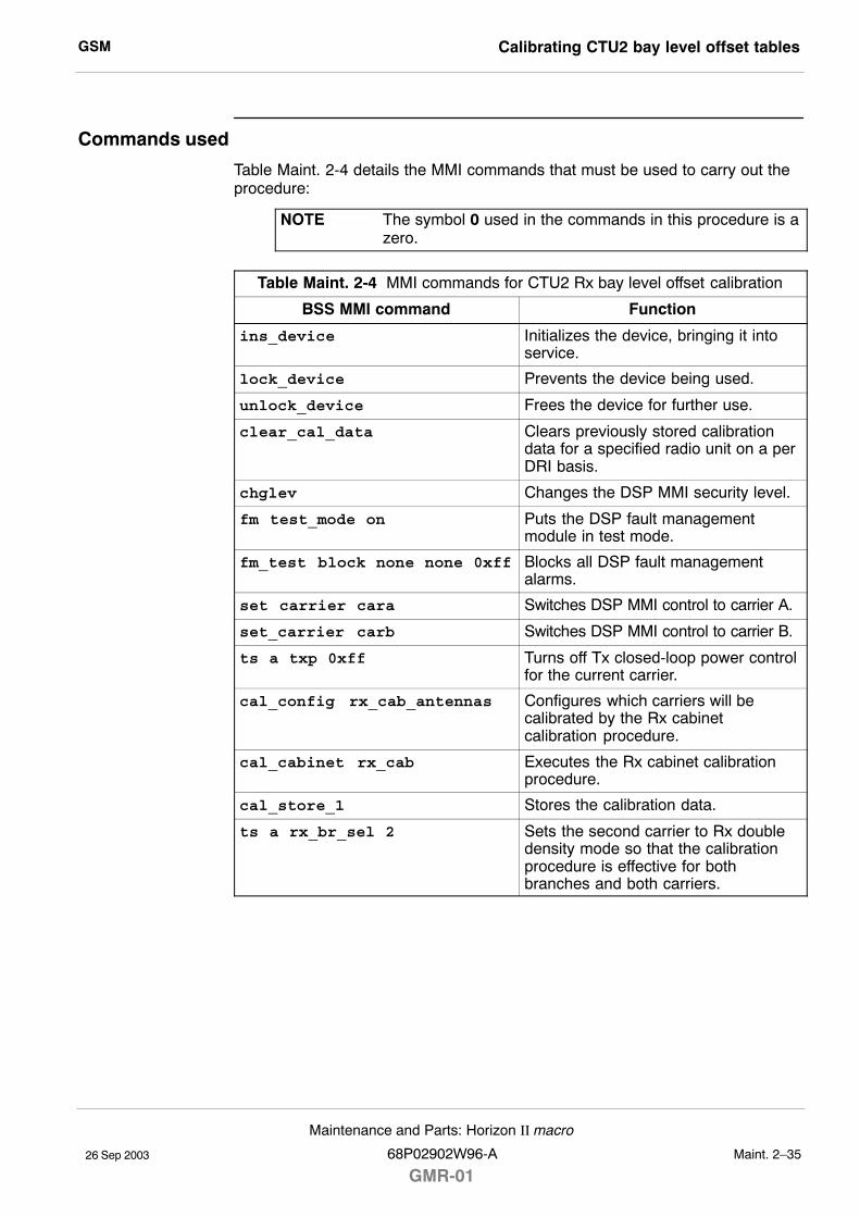
GSM Calibrating CTU2 bay level offset tables
26 Sep 2003
Maintenance and Parts: Horizon II macro
68P02902W96-A
GMR-01Maint. 2�35
Commands used
Table Maint. 2-4 details the MMI commands that must be used to carry out theprocedure:
NOTE The symbol 0 used in the commands in this procedure is azero.
Table Maint. 2-4 MMI commands for CTU2 Rx bay level offset calibration
BSS MMI command Function
ins_device Initializes the device, bringing it intoservice.
lock_device Prevents the device being used.
unlock_device Frees the device for further use.
clear_cal_data Clears previously stored calibrationdata for a specified radio unit on a perDRI basis.
chglev Changes the DSP MMI security level.
fm test_mode on Puts the DSP fault managementmodule in test mode.
fm_test block none none 0xff Blocks all DSP fault managementalarms.
set carrier cara Switches DSP MMI control to carrier A.
set_carrier carb Switches DSP MMI control to carrier B.
ts a txp 0xff Turns off Tx closed-loop power controlfor the current carrier.
cal_config rx_cab_antennas Configures which carriers will becalibrated by the Rx cabinetcalibration procedure.
cal_cabinet rx_cab Executes the Rx cabinet calibrationprocedure.
cal_store_1 Stores the calibration data.
ts a rx_br_sel 2 Sets the second carrier to Rx doubledensity mode so that the calibrationprocedure is effective for bothbranches and both carriers.
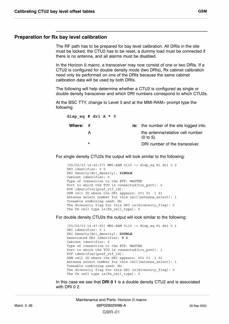
GSMCalibrating CTU2 bay level offset tables
26 Sep 2003Maint. 2�36
Maintenance and Parts: Horizon II macro
GMR-0168P02902W96-A
Preparation for Rx bay level calibration
The RF path has to be prepared for bay level calibration. All DRIs in the sitemust be locked, the CTU2 has to be reset, a dummy load must be connected ifthere is no antenna, and all alarms must be disabled.
In the Horizon II macro, a transceiver may now consist of one or two DRIs. If aCTU2 is configured for double density mode (two DRIs), Rx cabinet calibrationneed only be performed on one of the DRIs because the same cabinetcalibration data will be used by both DRIs.
The following will help determine whether a CTU2 is configured as single ordouble density transceiver and which DRI numbers correspond to which CTU2s.
At the BSC TTY, change to Level 3 and at the MMI-RAM> prompt type thefollowing:
disp_eq # dri A * 0
Where: # is: the number of the site logged into.
A the antenna/relative cell number(0 to 5).
* DRI number of the transceiver.
For single density CTU2s the output will look similar to the following:
[05/02/03 14:42:37] MMI–RAM 0115 –> disp_eq 81 dri 0 0DRI identifier: 0 0DRI Density[dri_density]: SINGLECabinet identifier: 0Type of connection to the BTP: MASTERPort to which the TCU is connected[tcu_port]: 0RTF identifier[pref_rtf_id]: GSM cell ID where the DRI appears: 001 01 1 91Antenna select number for this cell[antenna_select]: 1Tuneable combining used: NoThe diversity flag for this DRI is[diversity_flag]: 0The fm cell type is[fm_cell_type]: 0
For double density CTU2s the output will look similar to the following:
[05/02/03 14:47:55] MMI–RAM 0115 –> disp_eq 81 dri 0 1DRI identifier: 0 1DRI Density[dri_density]: DOUBLEAssociated DRI identifier: 0 2Cabinet identifier: 0Type of connection to the BTP: MASTERPort to which the TCU is connected[tcu_port]: 1RTF identifier[pref_rtf_id]: GSM cell ID where the DRI appears: 001 01 1 91Antenna select number for this cell[antenna_select]: 1Tuneable combining used: NoThe diversity flag for this DRI is[diversity_flag]: 0The fm cell type is[fm_cell_type]: 0
In this case we see that DRI 0 1 is a double density CTU2 and is associatedwith DRI 0 2.
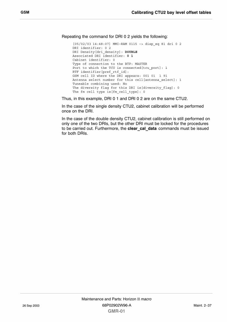
GSM Calibrating CTU2 bay level offset tables
26 Sep 2003
Maintenance and Parts: Horizon II macro
68P02902W96-A
GMR-01Maint. 2�37
Repeating the command for DRI 0 2 yields the following:
[05/02/03 14:48:07] MMI–RAM 0115 –> disp_eq 81 dri 0 2DRI identifier: 0 2DRI Density[dri_density]: DOUBLEAssociated DRI identifier: 0 1Cabinet identifier: 0Type of connection to the BTP: MASTERPort to which the TCU is connected[tcu_port]: 1RTF identifier[pref_rtf_id]: GSM cell ID where the DRI appears: 001 01 1 91Antenna select number for this cell[antenna_select]: 1Tuneable combining used: NoThe diversity flag for this DRI is[diversity_flag]: 0The fm cell type is[fm_cell_type]: 0
Thus, in this example, DRI 0 1 and DRI 0 2 are on the same CTU2.
In the case of the single density CTU2, cabinet calibration will be performedonce on the DRI.
In the case of the double density CTU2, cabinet calibration is still performed ononly one of the two DRIs, but the other DRI must be locked for the proceduresto be carried out. Furthermore, the clear_cal_data commands must be issuedfor both DRIs.
GSMCalibrating CTU2 bay level offset tables
26 Sep 2003Maint. 2�38
Maintenance and Parts: Horizon II macro
GMR-0168P02902W96-A
Rx bay level calibration procedureProceed as follows:
1. Connect the 9-way to 9-way HIISC cable from the PC serial A port to theHIISC TTY port.
2. At the PC, start the terminal emulator program.
3. Lock all DRIs in the sector. At the HIISC TTY, change to Level 3 and at theMMI-RAM> prompt type:
lock_device # dri A * 0
Where: # is: the number of the site logged into.
A the antenna/relative cell number(0 to 5).
* DRI number of the transceiver.
NOTE Always lock the transceiver providing the BCCH last asthis prevents the BCCH being switched to alternatetransceivers.
4. If a Tx antenna is not connected to the transceiver under test, connect a50 ohm 50 W dummy load to the Tx port.
5. Unlock the CTU2 to be calibrated. Change to Level 3 and at theMMI-RAM> prompt type:
ins_device # dri A * 0
Where: # is: the number of the site logged into.
A the antenna/relative cell number(0 to 5).
* DRI number of the transceiver.
NOTE In the case of a double density CTU2, Rx cabinetcalibration only needs to be performed on one of thetwo DRIs. The other DRI must remain locked.
6. Connect a serial port on the PC to the TTY Interface port on the CTU2 tobe calibrated using the 9-way to 9-way DSP MMI/RSS cable.
If necessary, switch the 9-way to 9-way DSP MMI/RSS cable fromproviding RSS connectivity to providing DSP connectivity.
7. At the DSP MMI prompt type:
chglev
and then enter the following password:
pizza
8. Enter calibration test mode and disable alarms by typing the followingcommands:
cal_test_mode on
fm test_mode on
fm_test block none none 0xff
GSM Calibrating CTU2 bay level offset tables
26 Sep 2003
Maintenance and Parts: Horizon II macro
68P02902W96-A
GMR-01Maint. 2�39
9. If required, set the second carrier to Rx double density mode by typing thefollowing command:
ts a rx_br_sel 2
This enables the calibration procedure to take effect on both branches andboth carriers.
10. Turn the CTU2�s transmitters off by typing the following at the DSP MMIprompt:
set_carrier cara
ts a txp 0xff
set_carrier carb
ts a txp 0xff
set_carrier cara
The response at the DSP MMI should be:
CTU2.carA.ts_0>
11. Configure which Rx antennas are to be calibrated using the followingcommand:
cal_config rx_cab_antennas <antenna> <antenna><antenna> <antenna> <antenna> <antenna>
Where <antenna> is one of the following:
all � All antennas.0a � Antenna 0A.1a � Antenna 1A.2a � Antenna 2A.0b � Antenna 0B.1b � Antenna 1B.2b � Antenna 2B.
Up to six antenna options can be specified, separated by spaces. Theoption all is equivalent to �0A 1A 2A 0B 1B 2B�.
For example, to calibrate antennas 0A and 0B, type the followingcommand:
cal_config rx_cab_antennas 0a 0b
The response will be:
Setting RX Cabinet Calibration antennas to: 0A 0B
To calibrate all antennas, type the following command:
cal_config rx_cab_antennas all
The response will be:
Setting RX Cabinet Calibration antennas to: ALL
GSMCalibrating CTU2 bay level offset tables
26 Sep 2003Maint. 2�40
Maintenance and Parts: Horizon II macro
GMR-0168P02902W96-A
12. Start the Rx cabinet calibration procedure by typing the followingcommand at the DSP MMI prompt:
cal_cabinet rx_cab
The following message will be displayed on the screen. This includes theSURF2 antenna connector to which the signal generator should beconnected (shown in bold text).
cal_cabinet rx_cabEnabling receive[c A, b 0] Setting RX diversity switch to double density(inject carrier A into carrier B)Enabling transmitNumber of frequency groups = 47
Please connect the signal generator to branch 0APress return when the signal generator is connected.
Press any key to continue
13. When the signal generator is connected to the appropriate SURF2antenna connector and configured, press ENTER at the DSP MMI prompt.
The on-screen instructions will list the new signal generator settingsrequired (shown in bold in the sample output below):
Please set the signal generator toPOWER –65.2000 dBmFREQ 1710.8052 MHz
Press any key to continue
Be sure to allow for any loss in the cables connecting the signal generatorto the antenna connector. For example, if the cables have a loss of 1.5 dBand you are asked to provide �65.2 dBm, set the signal generator to�63.7 dBm.
Make the appropriate adjustments and then press ENTER. The readingsfor each test frequency will look something like the following:
IQ average reading C0B0: 2565696, 0x00272640IQ average reading C1B0: 2762909, 0x002a289dMeasured gain: 14.76 (0x0ec2)Measured gain: 15.69 (0x0fb0)
Frequency group 2 of 47
Please set the signal generator toPOWER –65.2000 dBmFREQ 1712.4052 MHz
Press any key to continue
14. Repeat the calibration procedure in step 13 for all the appropriate testfrequencies (22 for EGSM and 47 for DCS1800).
15. Once all frequencies have been calibrated, the program will request thesignal generator is moved to the next SURF2 antenna connection (refer toexample message in step 12).
16. Repeat steps 13 and 14 for each antenna connection, until all frequencieson all antennas have been calibrated.
GSM Calibrating CTU2 bay level offset tables
26 Sep 2003
Maintenance and Parts: Horizon II macro
68P02902W96-A
GMR-01Maint. 2�41
17. Type the following command at the DSP MMI prompt when the calibrationprocedure has been completed:
cal_store_1
After a few seconds delay (up to 16 seconds), the result of the datastorage is displayed on the screen in the format:
cal_store_1PASSCTU2.carA.ts_0>
18. Take the CTU2 out of test mode by entering the following command:
fm test_mode off
19. Connect to the BSC MMI and enter the following command to lock theCTU2 that has been calibrated:
lock_device # dri A * 0
Where: #A
*
is: the number of the site logged into.the antenna/relative cell number(0 to 5).DRI number on the transceiver.
20. Clear the calibration data for both DRIs using the following command:
clear_cal_data # dri A * 0
NOTE The clear_cal_data command clears all calibration dataout of the CM database. This is required to override thepreserve calibration feature, if enabled.
21. Move the 9-way to 9-way DSP MMI/RSS cable to the CTU2 TTY port ofthe next CTU2 to be calibrated and repeat the procedure from step 4.
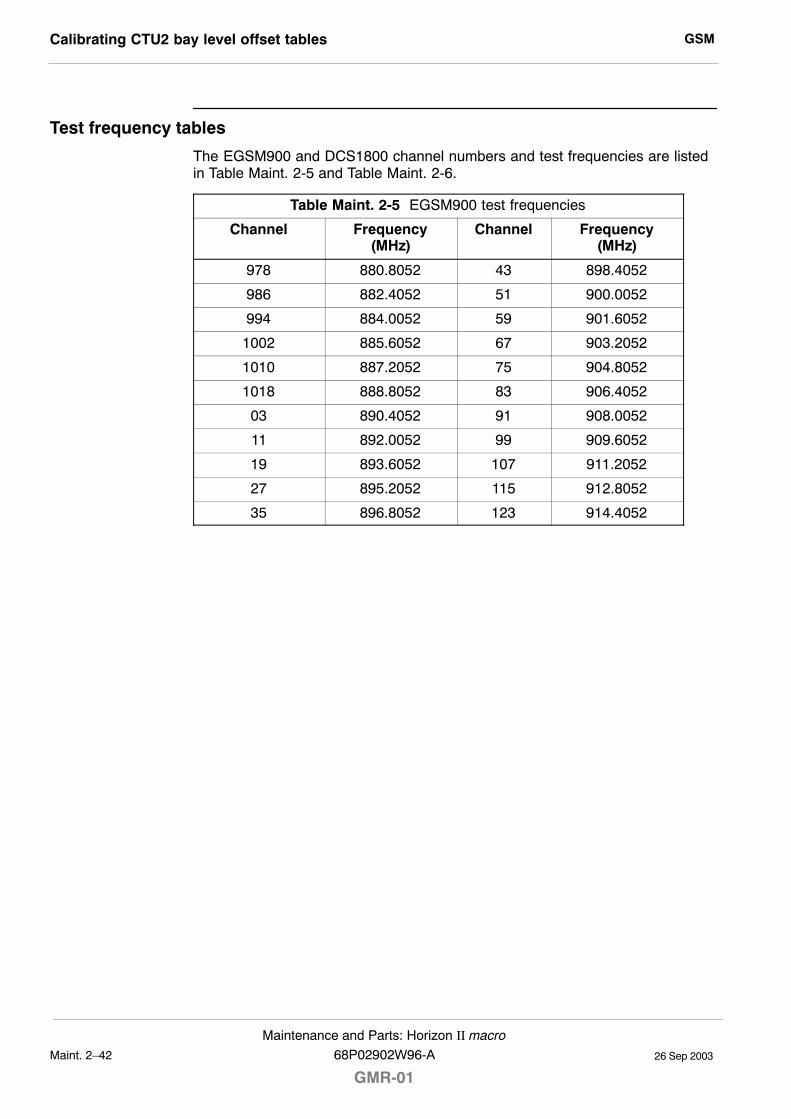
GSMCalibrating CTU2 bay level offset tables
26 Sep 2003Maint. 2�42
Maintenance and Parts: Horizon II macro
GMR-0168P02902W96-A
Test frequency tables
The EGSM900 and DCS1800 channel numbers and test frequencies are listedin Table Maint. 2-5 and Table Maint. 2-6.
Table Maint. 2-5 EGSM900 test frequencies
Channel Frequency(MHz)
Channel Frequency(MHz)
978 880.8052 43 898.4052
986 882.4052 51 900.0052
994 884.0052 59 901.6052
1002 885.6052 67 903.2052
1010 887.2052 75 904.8052
1018 888.8052 83 906.4052
03 890.4052 91 908.0052
11 892.0052 99 909.6052
19 893.6052 107 911.2052
27 895.2052 115 912.8052
35 896.8052 123 914.4052
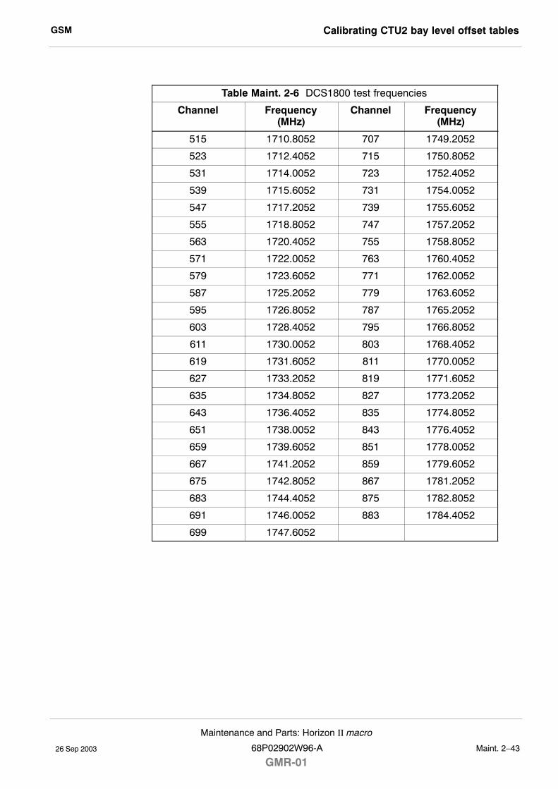
GSM Calibrating CTU2 bay level offset tables
26 Sep 2003
Maintenance and Parts: Horizon II macro
68P02902W96-A
GMR-01Maint. 2�43
Table Maint. 2-6 DCS1800 test frequencies
Channel Frequency(MHz)
Channel Frequency(MHz)
515 1710.8052 707 1749.2052
523 1712.4052 715 1750.8052
531 1714.0052 723 1752.4052
539 1715.6052 731 1754.0052
547 1717.2052 739 1755.6052
555 1718.8052 747 1757.2052
563 1720.4052 755 1758.8052
571 1722.0052 763 1760.4052
579 1723.6052 771 1762.0052
587 1725.2052 779 1763.6052
595 1726.8052 787 1765.2052
603 1728.4052 795 1766.8052
611 1730.0052 803 1768.4052
619 1731.6052 811 1770.0052
627 1733.2052 819 1771.6052
635 1734.8052 827 1773.2052
643 1736.4052 835 1774.8052
651 1738.0052 843 1776.4052
659 1739.6052 851 1778.0052
667 1741.2052 859 1779.6052
675 1742.8052 867 1781.2052
683 1744.4052 875 1782.8052
691 1746.0052 883 1784.4052
699 1747.6052
GSMCalibrating CTU2 bay level offset tables
26 Sep 2003Maint. 2�44
Maintenance and Parts: Horizon II macro
GMR-0168P02902W96-A
Site restoration
After the bay level calibration procedure is completed, restore the site by thefollowing:
1. Remove the signal generator and dummy load and reconnect the site RFcables.
2. Remove the 9-way to 9-way cable from the TTY interface port on theCTU2.
3. Connect the 9-way to 9-way cable from the PC serial A port to the HIISCTTY port.
CAUTION The following step must be carried out to initialize softwareand so ensure the CTU2 is correctly brought into service.
4. Reset the CTU2 by switching off the appropriate circuit breaker button onthe CBC and then switching on again. (The CTU2 does not have a frontpanel reset button.)
5. Type:
unlock_device # dri A * 0
Where: # is: the number of the site logged into.
A the antenna/relative cell number(0 to 5).
* DRI number on the transceiver.
The CTU2 is now in the unlocked_busy state.
6. Type:
disp_act_alarm # dri A * 0
Where: # is: the number of the site logged into.
A the antenna/relative cell number(0 to 5).
* DRI number on the transceiver.
Confirm that there is no DRI 218 alarm. If there is a DRI 218 alarm, redothe whole bay level calibration procedure
7. Remove the 9-way to 9-way cable from the HIISC TTY port.
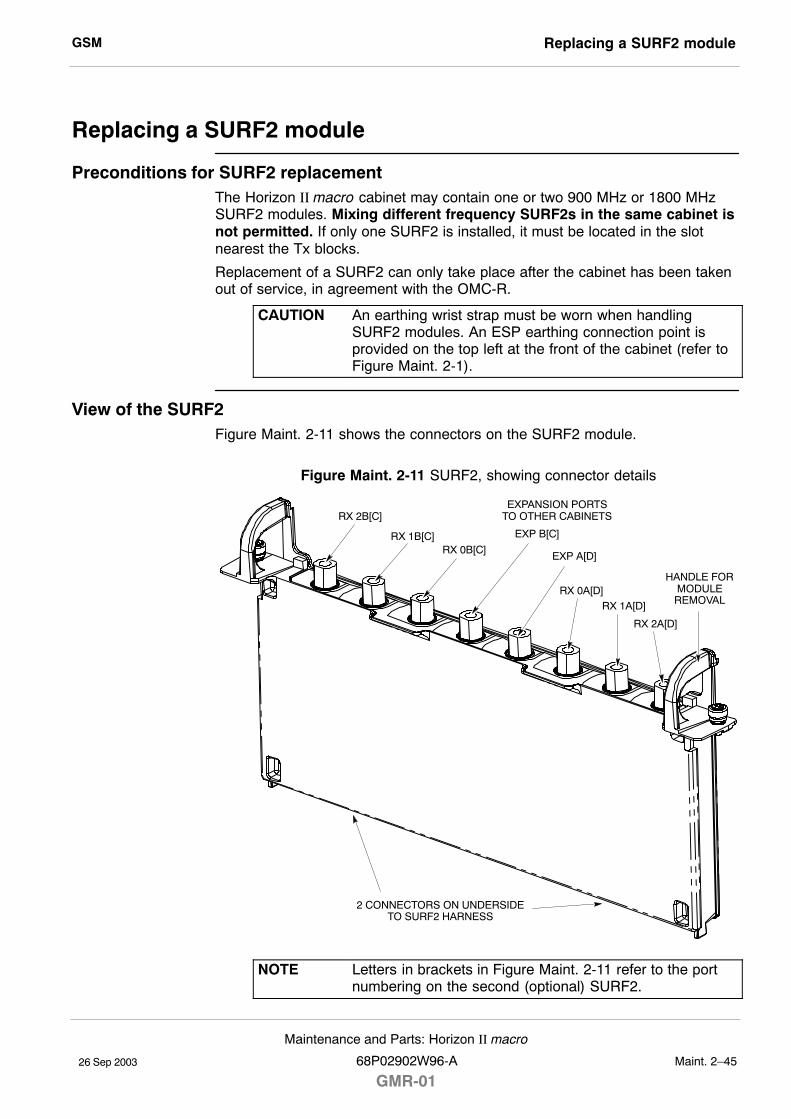
GSM Replacing a SURF2 module
26 Sep 2003
Maintenance and Parts: Horizon II macro
68P02902W96-A
GMR-01Maint. 2�45
Replacing a SURF2 module
Preconditions for SURF2 replacementThe Horizon II macro cabinet may contain one or two 900 MHz or 1800 MHzSURF2 modules. Mixing different frequency SURF2s in the same cabinet isnot permitted. If only one SURF2 is installed, it must be located in the slotnearest the Tx blocks.
Replacement of a SURF2 can only take place after the cabinet has been takenout of service, in agreement with the OMC-R.
CAUTION An earthing wrist strap must be worn when handlingSURF2 modules. An ESP earthing connection point isprovided on the top left at the front of the cabinet (refer toFigure Maint. 2-1).
View of the SURF2Figure Maint. 2-11 shows the connectors on the SURF2 module.
Figure Maint. 2-11 SURF2, showing connector details
RX 1B[C]
RX 2B[C]
RX 0B[C]
RX 0A[D]RX 1A[D]
RX 2A[D]
HANDLE FORMODULEREMOVAL
2 CONNECTORS ON UNDERSIDETO SURF2 HARNESS
EXPANSION PORTSTO OTHER CABINETS
EXP A[D]
EXP B[C]
NOTE Letters in brackets in Figure Maint. 2-11 refer to the portnumbering on the second (optional) SURF2.
GSMReplacing a SURF2 module
26 Sep 2003Maint. 2�46
Maintenance and Parts: Horizon II macro
GMR-0168P02902W96-A
Replacing a SURF2
Removing a faulty SURF2
To remove a SURF2:
1. Make a note of the RF cable connections to the SURF2 module to enablecorrect reconnection to the replacement module.
WARNING Before disconnecting RF cables, ensure that RF power isOFF. If RF power is ON when cables are disconnected,severe burns may result.
2. Disable all CTU2 transmit RF power by using the shutdown_devicecommand at the OMC-R or from a PC connected to the HIISC.
NOTE Refer to Technical Description: BSS Command Reference(68P02901W23) for information on usage and specificdevice codes.
3. When all CTU2s have been shutdown, check that all Tx STATUS LEDs(yellow) are unlit.
4. Press and release the CTU2 circuit breaker buttons on the CBC to the out(off) position. Ensure each RADIO STATUS LED is unlit.
5. Press and release the appropriate SURF2 circuit breaker button on theCBC to the out (off) position.
6. Disconnect the coaxial RF cables by carefully unscrewing and pullingthem out of the module sockets.
7. Using a Torx driver, unscrew the two M4 captive screws holding theSURF2 module to the top of the cabinet.
8. Using the handles, lift the SURF2 module out of the slot.
GSM Replacing a SURF2 module
26 Sep 2003
Maintenance and Parts: Horizon II macro
68P02902W96-A
GMR-01Maint. 2�47
Fitting a replacement SURF2 module
To install a replacement SURF2:
1. Transfer the protective caps on the RF connectors from the replacementmodule to the faulty module.
2. Lower the replacement SURF2 module into the slot. Take care to avoidtrapping cables as the module is seated.
3. Tighten the two captive M4 screws to the correct torque (refer toTable Maint. 2-1 at the start of this chapter).
4. Reconnect the coaxial RF cables to the positions noted in the removalprocedure. Tighten to the correct torque.
5. Switch on the SURF2 circuit breaker button on the CBC.
6. Reset the CTU2 circuit breaker buttons on the CBC. Each RADIOSTATUS LED will flash green for about two minutes, and then remain lit.
7. Enable the CTU2 transmit RF power by using the ins_device commandat the OMC-R or from a PC connected to the HIISC. The appropriate TxSTATUS LED (yellow) will be lit if the CTU2 is transmitting.
8. Notify the OMC-R of base station availability and log the maintenanceactivity.
The SURF2 module replacement is now complete.
GSMReplacing a Tx block, HCU/DHU or plate
26 Sep 2003Maint. 2�48
Maintenance and Parts: Horizon II macro
GMR-0168P02902W96-A
Replacing a Tx block, HCU/DHU or plate
Introduction to Tx block replacement
WARNING Ensure that RF power is OFF, before disconnecting RFcables. Severe burns may result if RF power is ON whenRF cables are disconnected.
CAUTION An earthing wrist strap must be worn when handling Txblocks. An ESP earthing connection point is provided onthe top left at the front of the cabinet (refer toFigure Maint. 2-1).
There are six slots for Tx blocks in the top panel basket of a cabinet, above theCTU2s. There are three types of Tx block: DUP, HCU and DHU.
Replacing a Tx block requires removal of RF transmitter power for the CTU2(s)that connect with the faulty Tx block. It is therefore advisable to perform thisprocedure during periods of low traffic. Notify the OMC-R of imminent repairactivity.
It is important to ensure that all Tx block/plate screw locations have a screw inplace which is tightened to the correct torque (refer to Table Maint. 2-1 at thestart of this chapter). This is to ensure the maximum quality of EMC and generalcontainment.
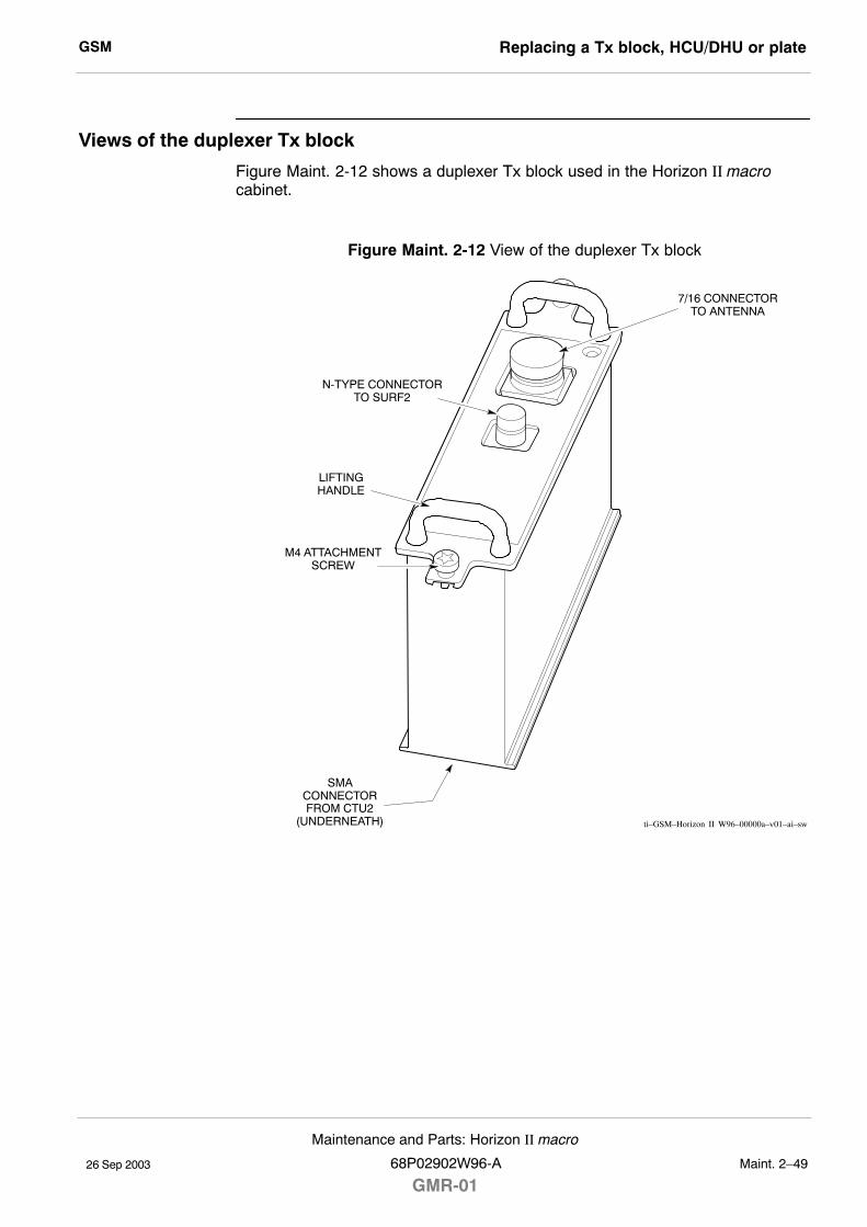
GSM Replacing a Tx block, HCU/DHU or plate
26 Sep 2003
Maintenance and Parts: Horizon II macro
68P02902W96-A
GMR-01Maint. 2�49
Views of the duplexer Tx block
Figure Maint. 2-12 shows a duplexer Tx block used in the Horizon II macrocabinet.
Figure Maint. 2-12 View of the duplexer Tx block
ti�GSM�Horizon II W96�00000a�v01�ai�sw
M4 ATTACHMENTSCREW
N-TYPE CONNECTORTO SURF2
7/16 CONNECTORTO ANTENNA
LIFTINGHANDLE
SMACONNECTORFROM CTU2
(UNDERNEATH)
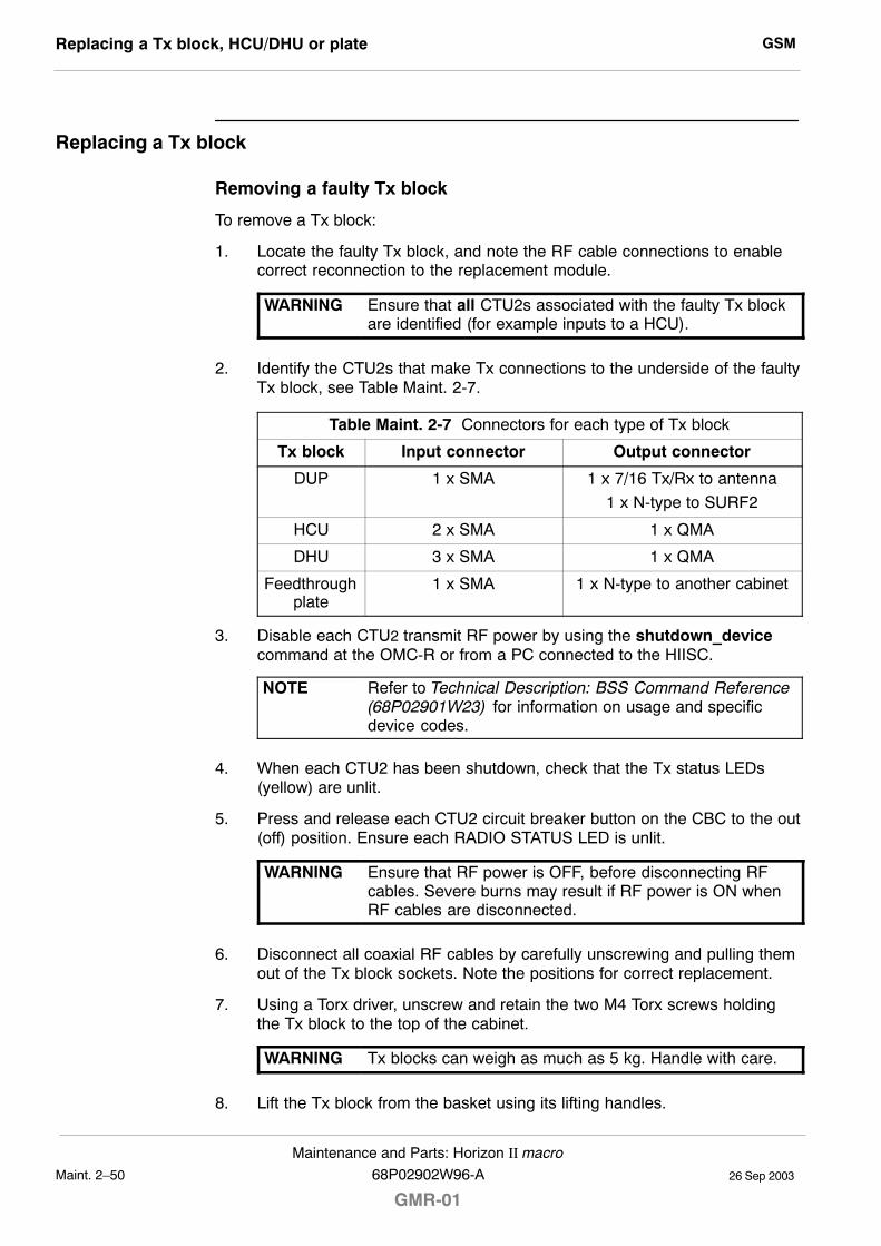
GSMReplacing a Tx block, HCU/DHU or plate
26 Sep 2003Maint. 2�50
Maintenance and Parts: Horizon II macro
GMR-0168P02902W96-A
Replacing a Tx block
Removing a faulty Tx block
To remove a Tx block:
1. Locate the faulty Tx block, and note the RF cable connections to enablecorrect reconnection to the replacement module.
WARNING Ensure that all CTU2s associated with the faulty Tx blockare identified (for example inputs to a HCU).
2. Identify the CTU2s that make Tx connections to the underside of the faultyTx block, see Table Maint. 2-7.
Table Maint. 2-7 Connectors for each type of Tx block
Tx block Input connector Output connector
DUP 1 x SMA 1 x 7/16 Tx/Rx to antenna
1 x N-type to SURF2
HCU 2 x SMA 1 x QMA
DHU 3 x SMA 1 x QMA
Feedthroughplate
1 x SMA 1 x N-type to another cabinet
3. Disable each CTU2 transmit RF power by using the shutdown_devicecommand at the OMC-R or from a PC connected to the HIISC.
NOTE Refer to Technical Description: BSS Command Reference(68P02901W23) for information on usage and specificdevice codes.
4. When each CTU2 has been shutdown, check that the Tx status LEDs(yellow) are unlit.
5. Press and release each CTU2 circuit breaker button on the CBC to the out(off) position. Ensure each RADIO STATUS LED is unlit.
WARNING Ensure that RF power is OFF, before disconnecting RFcables. Severe burns may result if RF power is ON whenRF cables are disconnected.
6. Disconnect all coaxial RF cables by carefully unscrewing and pulling themout of the Tx block sockets. Note the positions for correct replacement.
7. Using a Torx driver, unscrew and retain the two M4 Torx screws holdingthe Tx block to the top of the cabinet.
WARNING Tx blocks can weigh as much as 5 kg. Handle with care.
8. Lift the Tx block from the basket using its lifting handles.
GSM Replacing a Tx block, HCU/DHU or plate
26 Sep 2003
Maintenance and Parts: Horizon II macro
68P02902W96-A
GMR-01Maint. 2�51
Fitting a replacement Tx block
To install a replacement Tx block:
1. Transfer the protective caps on the RF connectors from the replacementTx block to the faulty Tx block.
2. Carefully insert the replacement Tx block into its basket location on the toppanel, adjusting alignment for the retaining screws. Take care to avoidtrapping cables as the Tx block is seated.
3. Fit the two M4 Torx screws that secure the Tx block to the top of thecabinet. Tighten to the correct torque (refer to Table Maint. 2-1 at the startof this chapter).
4. Reconnect the coaxial RF cables to the positions noted in the removalprocedure. Tighten to the correct torque.
NOTE Ensure all unused SMA inputs to the Tx blocks are fittedwith 50 ohm load terminations.
5. Switch on the appropriate CTU2 circuit breaker buttons on the CBC. EachRADIO STATUS LED will flash green for about two minutes, and thenremain lit.
6. Enable the CTU2 transmit RF power by using the ins_device commandat the OMC-R or from a PC connected to the HIISC. The appropriate TxSTATUS LED (yellow) will be lit if the CTU2 is transmitting.
7. Notify the OMC-R of base station availability and log the maintenanceactivity.
Blanking plate, feedthrough plate or HCU/DHU replacement
The replacement procedure for plates or a HCU/DHU is similar to that describedfor Tx blocks, but the plates are held by three M4 screws in the base of the Txblock basket. The two M4 Tx block screw locations are not used for plateattachment.
CAUTION Unused Tx block locations must be covered with ablanking plate, with all screws fitted and tightened to thecorrect torque (see Table Maint. 2-1) to ensure the correctairflow and EMC shielding.
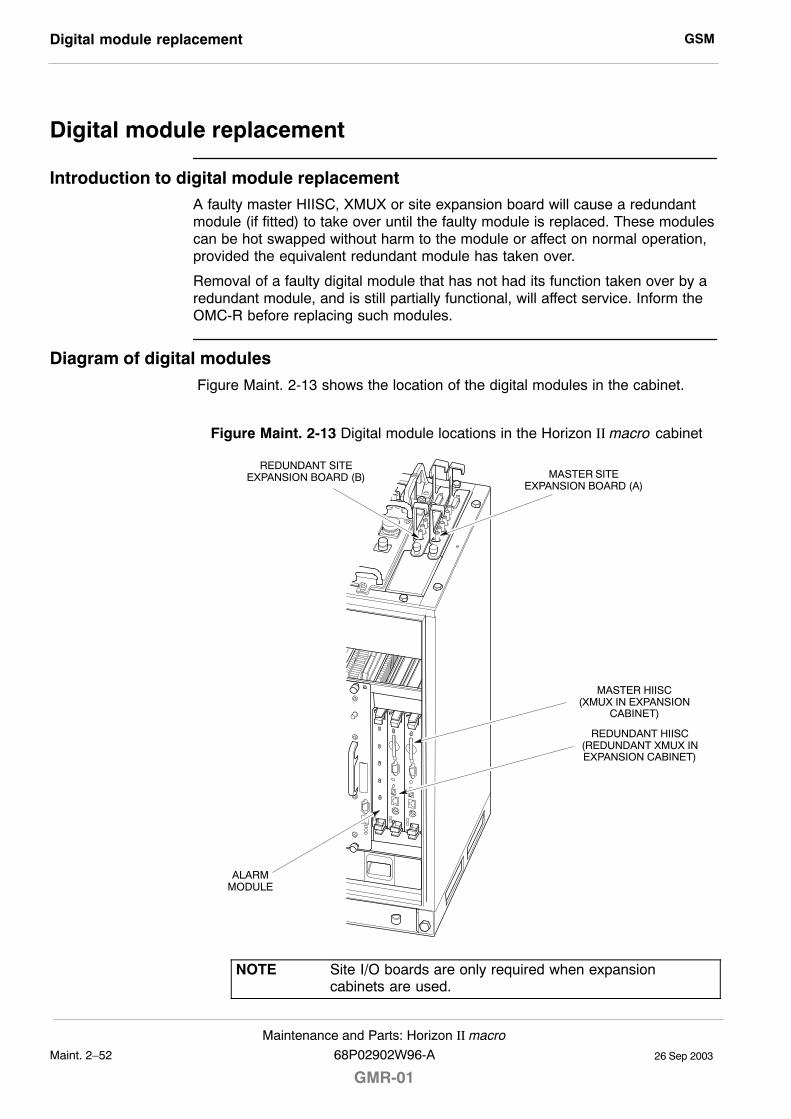
GSMDigital module replacement
26 Sep 2003Maint. 2�52
Maintenance and Parts: Horizon II macro
GMR-0168P02902W96-A
Digital module replacement
Introduction to digital module replacementA faulty master HIISC, XMUX or site expansion board will cause a redundantmodule (if fitted) to take over until the faulty module is replaced. These modulescan be hot swapped without harm to the module or affect on normal operation,provided the equivalent redundant module has taken over.
Removal of a faulty digital module that has not had its function taken over by aredundant module, and is still partially functional, will affect service. Inform theOMC-R before replacing such modules.
Diagram of digital modules
Figure Maint. 2-13 shows the location of the digital modules in the cabinet.
Figure Maint. 2-13 Digital module locations in the Horizon II macro cabinet
ALARMMODULE
MASTER SITEEXPANSION BOARD (A)
REDUNDANT SITEEXPANSION BOARD (B)
REDUNDANT HIISC(REDUNDANT XMUX INEXPANSION CABINET)
MASTER HIISC(XMUX IN EXPANSION
CABINET)
NOTE Site I/O boards are only required when expansioncabinets are used.
GSM Digital module replacement
26 Sep 2003
Maintenance and Parts: Horizon II macro
68P02902W96-A
GMR-01Maint. 2�53
Replacing digital modules
CAUTION HIISC removal during flash memory programming mayresult in boot code corruption. This is only repairable byreturning the HIISC to Motorola. For this reason, the HIISCshould not be removed while the code load is taking place,indicated by flashing red and green front panel LEDs.
Removing a faulty digital module
To remove a digital module:
CAUTION An earthing wrist strap must be worn when handling digitalmodules. An ESP earthing connection point is provided onthe top left at the front of the cabinet (refer toFigure Maint. 2-1).
1. If the faulty digital module is still partially functional, due to no redundancyoption, inform the OMC-R before proceeding.
2. Locate the faulty module, as shown in Figure Maint. 2-13.
3. Note location of any fibre optic cable connections to the module, (siteexpansion boards only), to enable correct reconnection to the replacementmodule.
WARNING There is a possibility of laser radiation when fibre opticcables are disconnected. Do not look directly into cableswith or without the use of any optical aids. Radiation cancome from either the data in/out connectors orunterminated fibre optic cables connected to data in/outconnectors.
4. Remove strain relief clips and disconnect each fibre optic cable by gentlypushing the knurled connector in and rotating it through a quarter-turnanticlockwise to disengage, then withdraw the cable carefully.
NOTE It is advisable to protect the tips of the fibre optic cableswith a protective cover and secure the cables to one side.
5. For the HIISC/XMUX or alarm module, unseat the module by gripping theupper and lower pair of ejectors between the thumb and first finger of eachhand, then gently squeeze and pull on the ejectors until the moduleunclips at the top and bottom of the front panel and unplugs from the rearconnector.
Carefully slide the module from its location and place it in an anti-staticstorage container.
6. For the site expansion board, undo the single M4 attachment screw andcarefully lift the board out of its slot using the handles provided and placeit in an anti-static storage container.
GSMDigital module replacement
26 Sep 2003Maint. 2�54
Maintenance and Parts: Horizon II macro
GMR-0168P02902W96-A
Fitting replacement digital module
To install a replacement digital module:
1. Remove the replacement module from the anti-static storage container.
2. For the HIISC/XMUX or alarm module, slide the module into the guide railsand push firmly into place. The ejectors will audibly click into place asconfirmation of correct insertion.
3. For the site expansion board, lower the board into its slot using thehandles provided. Ensure the backplane interface connector on the baseis firmly seated in position and then tighten the M4 attachment screw tothe correct torque using a Torxdriver.
4. Connect any fibre optic cables by inserting the connector and rotating aquarter-turn clockwise to engage. Fit strain relief clips around the fibreoptic cables and secure to one of the site expansion board handles (slotsare provided in the handles for this purpose).
NOTE Ensure fibre optic cables are correctly connected to thelocations noted during site expansion board removal.
5. Ensure the appropriate LEDs indicate correct operation.
CAUTION When the red and green ALARM and STATUS LEDs onthe front panel the HIISC are flashing, the boot code isdownloading into non-volatile memory for softwareupgrade. Do not remove power or reset the cabinet untildownloading has been completed, as this will corrupt thenon-volatile memory.If the boot code is corrupted, contact Motorola CustomerNetwork Resolution Centre requesting the boot coderestoration procedure and the appropriate boot code file.
6. When fitting a redundant HIISC, refer to Redundant HIISC firmwarecompatibility for details of further checks required.
7. Notify the OMC-R of base station availability and log the maintenanceactivity.
GSM Testing HIISC redundancy
26 Sep 2003
Maintenance and Parts: Horizon II macro
68P02902W96-A
GMR-01Maint. 2�55
Testing HIISC redundancy
Test procedure
The following procedure tests HIISC redundancy (if used) by forcing the masterand redundant HIISCs to swap roles. The commands refer to the basetransceiver processors (BTPs) within each HIISC.
NOTE Forcing a switch to the redundant HIISC by using theswap_devices command will cause a site reset.
1. Connect a PC to the TTY MMI port on the master HIISC.
2. At the CUST MMI prompt, type:
state <site #> btp * *
Where <site #> is the site number.
The status of both BTPs will be displayed as follows:
BTP 0 0 0 B–U NO REASON
BTP 1 0 0 E–U NO REASON
Where B–U is busy unlocked (master) and E-U is enabled unlocked(redundant).
3. At the CUST MMI prompt type:
swap_devices <site #> btp 0 0 0 btp 1 0 0
Where <site #> is the site number, btp 0 0 0 is the master HIISC and btp1 0 0 is the redundant HIISC.
This command will swap HIISC roles by forcing:
S the redundant HIISC into a busy state , and making it master.
S the master HIISC into an enabled state, and making it redundant.
4. At the CUST MMI prompt, confirm the swap by typing:
state <site #> btp * *
Where <site #> is the site number.
The status of both BTPs will now show changed roles:
BTP 0 0 0 E–U NO REASON
BTP 1 0 0 B–U NO REASON
5. Make test calls on the site to verify the new master HIISC.
6. At the CUST MMI prompt type, swap the HIISCs back to their originalstates by typing:
swap_devices <site #> btp 1 0 0 btp 0 0 0
Where <site #> is the site number, btp 1 0 0 is the master HIISC and btp0 0 0 is the redundant HIISC.
GSMTesting HIISC redundancy
26 Sep 2003Maint. 2�56
Maintenance and Parts: Horizon II macro
GMR-0168P02902W96-A
7. At the CUST MMI prompt, confirm the swap by typing:
state <site #> btp * *
Where <site #> is the site number.
Both BTPs have now reverted to their original roles:
BTP 0 0 0 B–U NO REASON
BTP 1 0 0 E–U NO REASON
8. Make test calls on the site to verify the new master HIISC.
GSM Calibrating the HIISC (GCLK)
26 Sep 2003
Maintenance and Parts: Horizon II macro
68P02902W96-A
GMR-01Maint. 2�57
Calibrating the HIISC (GCLK)
Introduction to HIISC (GCLK) calibration
NOTE GCLK calibration can be carried out automatically usingthe CINDY commissioning tool. Refer to the relevantCINDY user documentation for details.
This procedure explains how to calibrate the Ovenized Crystal Oscillator(OCXO) in the HIISC GCLK in the Horizon II macro product at a BSS site.
When to calibrate the GCLK
The calibration procedure is to be used on the following occasions:
S When more than one frame slip per hour is observed at the OMC-R(typically more than 34/day).
S Whenever calibration is required. (Display the active alarms for a site - ifcalibration is required, there will be an alarm stating this.)
CAUTION This procedure should only be carried out by fully trained,GSM qualified personnel. Under NO circumstances shouldthis procedure be undertaken, unless all the correct testequipment is readily available.
NOTE The command gclk_cal_mode used in this procedureshould only be executed at the BTS where the calibrationis being carried out.No call processing can occur involving the HIISC duringcalibration mode.Allow a period of 15 minutes to elapse after switching theOCXO power on, to give sufficient time for the unit toreach operating temperature and achieve frequencystabilization.
Test equipment required
The test equipment required to carry out the GCLK calibration is as follows:
S An IBM compatible personal computer (PC).
S A 9-way to 9-way TTY cable.
S A caesium or rubidium clock standard with 1 or 10 MHz output frequency.
S A universal counter with external reference, for example, the HewlettPackard model HP5385A or equivalent.
S A BNC to 3-way HIISC test lead, part number 3086144E01.
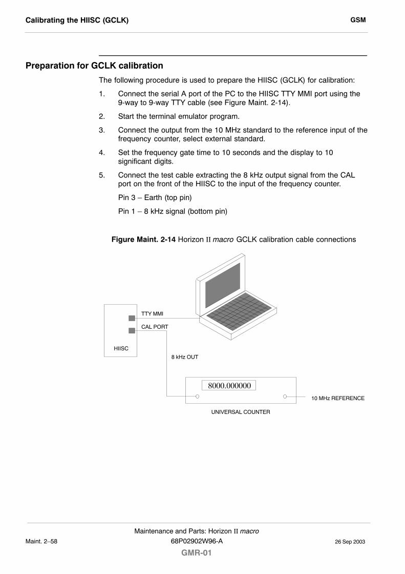
GSMCalibrating the HIISC (GCLK)
26 Sep 2003Maint. 2�58
Maintenance and Parts: Horizon II macro
GMR-0168P02902W96-A
Preparation for GCLK calibration
The following procedure is used to prepare the HIISC (GCLK) for calibration:
1. Connect the serial A port of the PC to the HIISC TTY MMI port using the9-way to 9-way TTY cable (see Figure Maint. 2-14).
2. Start the terminal emulator program.
3. Connect the output from the 10 MHz standard to the reference input of thefrequency counter, select external standard.
4. Set the frequency gate time to 10 seconds and the display to 10significant digits.
5. Connect the test cable extracting the 8 kHz output signal from the CALport on the front of the HIISC to the input of the frequency counter.
Pin 3 � Earth (top pin)
Pin 1 � 8 kHz signal (bottom pin)
Figure Maint. 2-14 Horizon II macro GCLK calibration cable connections
8000.000000
HIISC
TTY MMI
8 kHz OUT
UNIVERSAL COUNTER
10 MHz REFERENCE
CAL PORT
GSM Calibrating the HIISC (GCLK)
26 Sep 2003
Maintenance and Parts: Horizon II macro
68P02902W96-A
GMR-01Maint. 2�59
GCLK calibration procedure
The following procedure is used to calibrate the HIISC (GCLK).
1. To start the GCLK calibration mode, enter the command:
gclk_cal_mode
The gclk_cal_mode command is used to tell the sync function andHIISC software that a calibration is to be performed.
NOTE The gclk_cal_mode command is used to tell the syncfunction and HIISC software that a calibration is to beperformed and can only be executed at Horizon II macrosites outside sysgen mode. The command is NOT allowedon a master HIISC when a standby HIISC is available.
When the command is executed the system will prompt for verification:
Site <Local site number> starting GCLK CALIBRATION MODE. If this isa single MCU site, the site will be down until calibration iscomplete.
Are you sure (y=yes, n=no)?
Enter:
y
The HIISC will begin calibration mode. The command is aborted if thereply is anything other than y.
2. After a short delay (about 30 seconds) the following prompt will appear:
Frequency Counter Connected, Enter y when ready, or a to abort test.
Enter:
y
The command is aborted and calibration mode exited if the reply isanything other than y.
GSMCalibrating the HIISC (GCLK)
26 Sep 2003Maint. 2�60
Maintenance and Parts: Horizon II macro
GMR-0168P02902W96-A
3. Adjust the OCXO control voltage using the +/� and 0 to 3 keys until themeasured frequency is exactly 8000,000000 Hz.
The values entered here, change the frequency by varying degrees. Forexample:
� +0 will increase the output by a small amount.
� +1 will increase the frequency by approximately 10 times.
� +2 will increase the frequency by approximately 100 times.
� +3 will increase the frequency by approximately 1000 times.
These are not exact values as every OCXO has a different gain. Thismethod gives sufficient control to correct the frequency within a short time.
A typical sequence of numbers may look as follows:
Enter a to abort. s to save, +(0..3) to inc, –(0..3) to dec >–3(7.99999898)
Enter a to abort. s to save, +(0..3) to inc, –(0..3) to dec >+3(8.00000020)
Enter a to abort. s to save, +(0..3) to inc, –(0..3) to dec >–0(8.00000019 - 8.00000020)
Enter a to abort. s to save, +(0..3) to inc, –(0..3) to dec >–2(8.00000004)
Enter a to abort. s to save, +(0..3) to inc, –(0..3) to dec >+2(8.00000020)
Enter a to abort. s to save, +(0..3) to inc, –(0..3) to dec >–1(8.00000018)
Enter a to abort. s to save, +(0..3) to inc, –(0..3) to dec >–2(8.00000002 -8.00000003)
Enter a to abort. s to save, +(0..3) to inc, –(0..3) to dec >–1(8.000000--)
Enter a to abort. s to save, +(0..3) to inc, –(0..3) to dec >+0(8.000000-)
Enter a to abort. s to save, +(0..3) to inc, –(0..3) to dec >+0(8.00000000)
4. A prompt will appear for saving the results:
Enter a to abort, s to save, +(0..3) to inc, –(0..3) to dec >
Enter:
s
CAL OFFSET is 23654 DAC bits.
After calibration, the HIISC applies a set of voltages to the DAC that feedsthe OCXO, requiring the user to input the corresponding output frequency.This is necessary because the OCXO frequency/voltage characteristic isnot linear and the HIISC adjusts for this by taking readings across a rangeof DAC voltages.
GSM Calibrating the HIISC (GCLK)
26 Sep 2003
Maintenance and Parts: Horizon II macro
68P02902W96-A
GMR-01Maint. 2�61
5. To calibrate the OCXO, gain, enter the measured frequency value from thecounter after the value has settled in response to the MMI prompts.
NOTE When taking frequency measurements, ensure that a fullgate period elapses from the time the new value is set toreading the counter. This wait may be several secondsdepending on the counter.
A typical sequence of frequency measurements may be presented asfollows:
Dac set to 1.0 volts, Enter Freq Value or a to abort > 7999.99853
Dac set to 2.0 volts, Enter Freq Value or a to abort > 7999.99915
Dac set to 3.0 volts, Enter Freq Value or a to abort > 7999.99969
Dac set to 4.0 volts, Enter Freq Value or a to abort > 8000.00020
Dac set to 5.0 volts, Enter Freq Value or a to abort > 8000.00070
Dac set to 6.0 volts, Enter Freq Value or a to abort > 8000.00122
Dac set to 7.0 volts, Enter Freq Value or a to abort > 8000.00176
Calibration Gain 3.865560e-01
SYNC>
NOTE The HIISC is reset when the calibration is complete.
6. On completion, the HIISC will automatically reject the calibration if it isoutside the threshold and the following message will be displayed:
Computed Gain > Max WILL RETRY GAIN
Calibration must be performed again. If calibration fails the second timewith the same or similar value, the OCXO may be operating outside theMotorola specification, in which case the HIISC is deemed faulty andshould be replaced.

GSMCalibrating the HIISC (GCLK)
26 Sep 2003Maint. 2�62
Maintenance and Parts: Horizon II macro
GMR-0168P02902W96-A
26 Sep 2003
Maintenance and Parts: Horizon II macro
68P02902W96-A
GMR-01Maint. 3�1
Chapter 3
Site verification procedures

GSM
26 Sep 2003Maint. 3�2
Maintenance and Parts: Horizon II macro
GMR-0168P02902W96-A
GSM Introduction to Horizon II macro verification procedures
26 Sep 2003
Maintenance and Parts: Horizon II macro
68P02902W96-A
GMR-01Maint. 3�3
Introduction to Horizon II macro verification procedures
Purpose of this chapter
This chapter provides information required for the verification of theHorizon II macro hardware equipment.
The procedures described in this chapter are as follows:
S Checking the antenna VSWR and calibrating the transmit output power.
S Checking the database equipage.
S Checking the E1/T1 link.
S Checking the PIX connections and alarm test.
CINDY commissioning tool
Many of the procedures described in this chapter can be carried outautomatically using the CINDY commissioning tool. Refer to the relevant CINDYuser documentation for details.
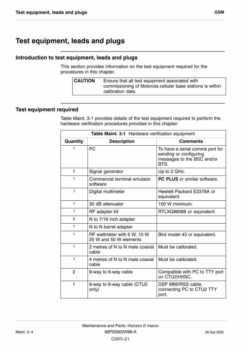
GSMTest equipment, leads and plugs
26 Sep 2003Maint. 3�4
Maintenance and Parts: Horizon II macro
GMR-0168P02902W96-A
Test equipment, leads and plugs
Introduction to test equipment, leads and plugs
This section provides information on the test equipment required for theprocedures in this chapter.
CAUTION Ensure that all test equipment associated withcommissioning of Motorola cellular base stations is withincalibration date.
Test equipment required
Table Maint. 3-1 provides details of the test equipment required to perform thehardware verification procedures provided in this chapter:
Table Maint. 3-1 Hardware verification equipment
Quantity Description Comments
1 PC To have a serial comms port forsending or configuringmessages to the BSC and/orBTS.
1 Signal generator Up to 2 GHz.
1 Commercial terminal emulatorsoftware
PC PLUS or similar software.
1 Digital multimeter Hewlett Packard E2378A orequivalent.
1 30 dB attenuator 100 W minimum.
1 RF adapter kit RTLXQ98088 or equivalent.
2 N to 7/16 inch adapter
1 N to N barrel adapter
1 RF wattmeter with 5 W, 10 W25 W and 50 W elements
Bird model 43 or equivalent.
1 2 metres of N to N male coaxialcable
Must be calibrated.
1 4 metres of N to N male coaxialcable
Must be calibrated.
2 9-way to 9-way cable Compatible with PC to TTY porton CTU2/HIISC.
1 9-way to 9-way cable (CTU2only)
DSP MMI/RSS cable,connecting PC to CTU2 TTYport.
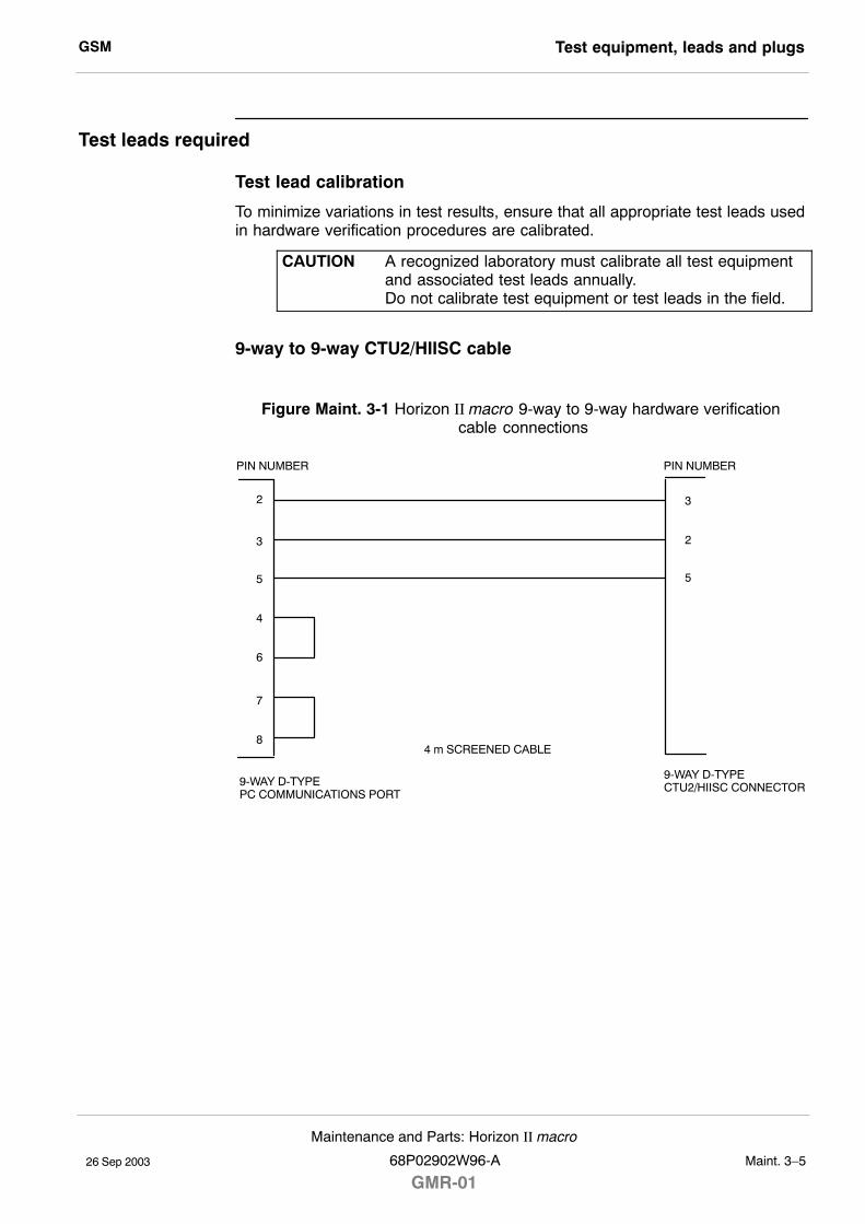
GSM Test equipment, leads and plugs
26 Sep 2003
Maintenance and Parts: Horizon II macro
68P02902W96-A
GMR-01Maint. 3�5
Test leads required
Test lead calibration
To minimize variations in test results, ensure that all appropriate test leads usedin hardware verification procedures are calibrated.
CAUTION A recognized laboratory must calibrate all test equipmentand associated test leads annually.Do not calibrate test equipment or test leads in the field.
9-way to 9-way CTU2/HIISC cable
Figure Maint. 3-1 Horizon II macro 9-way to 9-way hardware verification cable connections
2
23
3
55
4
6
7
8
PIN NUMBER PIN NUMBER
9-WAY D-TYPEPC COMMUNICATIONS PORT
9-WAY D-TYPECTU2/HIISC CONNECTOR
4 m SCREENED CABLE
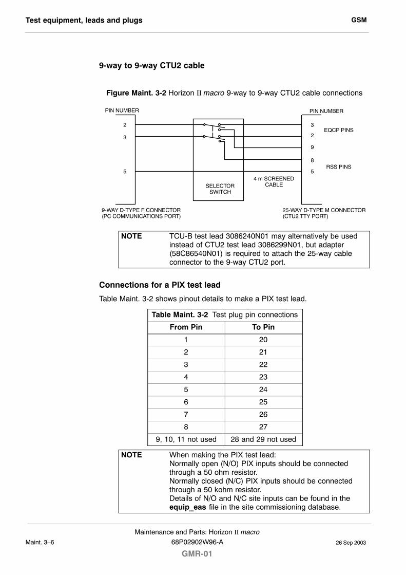
GSMTest equipment, leads and plugs
26 Sep 2003Maint. 3�6
Maintenance and Parts: Horizon II macro
GMR-0168P02902W96-A
9-way to 9-way CTU2 cable
Figure Maint. 3-2 Horizon II macro 9-way to 9-way CTU2 cable connections
EQCP PINS
RSS PINS
25-WAY D-TYPE M CONNECTOR(CTU2 TTY PORT)
9-WAY D-TYPE F CONNECTOR(PC COMMUNICATIONS PORT)
4 m SCREENEDCABLE
PIN NUMBER
SELECTORSWITCH
PIN NUMBER
2
2
3
3
8
5
9
5
NOTE TCU-B test lead 3086240N01 may alternatively be usedinstead of CTU2 test lead 3086299N01, but adapter(58C86540N01) is required to attach the 25-way cableconnector to the 9-way CTU2 port.
Connections for a PIX test lead
Table Maint. 3-2 shows pinout details to make a PIX test lead.
Table Maint. 3-2 Test plug pin connections
From Pin To Pin
1 20
2 21
3 22
4 23
5 24
6 25
7 26
8 27
9, 10, 11 not used 28 and 29 not used
NOTE When making the PIX test lead:Normally open (N/O) PIX inputs should be connectedthrough a 50 ohm resistor.Normally closed (N/C) PIX inputs should be connectedthrough a 50 kohm resistor.Details of N/O and N/C site inputs can be found in theequip_eas file in the site commissioning database.
GSM CTU2 VSWR and cell site offset information
26 Sep 2003
Maintenance and Parts: Horizon II macro
68P02902W96-A
GMR-01Maint. 3�7
CTU2 VSWR and cell site offset information
Introduction to output power calibration and VSWR check
NOTE CTU2 cell site offset calibration and VSWR checks can becarried out automatically using the CINDY commissioningtool. Refer to the relevant CINDY user documentation fordetails.
The objective of the VSWR check and output power calibration procedure is toensure that antenna feeders and connectors are properly terminated and thenset the pre-defined maximum transmitter output power at the top of the cabinet.
When a transceiver is manufactured, it undergoes comprehensive transmit andreceive calibration procedures. These procedures aim to produce a transceiverthat exhibits a flat frequency response over the GSM band. In the case of thetransmitter, this is performed by distributing the channels over three detectorgroups (the detector being the device that maintains a steady output powerlevel).
In the field, the procedure for setting the transmit output power involves using aset of commands called Cell Site Power (CSPWR). During CSPWR the user cantrim the cabinet output power to account for any abnormalities that may occurbetween the CTU2 and the top of the cabinet. The offset is effectivelysubtracted from the requested power level, such that for whatever channel isselected, a steady output is maintained at the top of the cabinet.
The Preparing for test procedure at the end of this section should becompleted before attempting the VSWR and cell site power calibrationprocedures.
GSMCTU2 VSWR and cell site offset information
26 Sep 2003Maint. 3�8
Maintenance and Parts: Horizon II macro
GMR-0168P02902W96-A
Test equipment required
The following test equipment is required during the VSWR and output powercalibration procedure:
S An IBM-compatible personal computer (PC).
S Terminal emulator software.
S A Bird model 43P (Thru-line) wattmeter, or equivalent, with 5 W and 50 Welements.
S A 9-way to 9-way cable (a diagram of this cable is provided in the Testequipment, leads and plugs section).
S A 9-way to 9-way DSP MMI/RSS cable.
S A 7/16 N-type adapter.
S A 50 ohm/100 W power attenuator.
CAUTION All test equipment and test leads must be calibratedannually by a recognized laboratory. Test equipment andtest leads must not be calibrated in the field.Do not optimize Motorola cellular base stations with testequipment that is beyond its calibration due date.Allow test equipment to warm up for 30 minutes beforeuse.
GSM CTU2 VSWR and cell site offset information
26 Sep 2003
Maintenance and Parts: Horizon II macro
68P02902W96-A
GMR-01Maint. 3�9
Commands used
Table Maint. 3-3 lists the commands for the VSWR and output power calibrationprocedure.
NOTE The symbol 0 used in the commands is a zero.
Table Maint. 3-3 VSWR and power calibration commands
BSS MMI Command Function
ins_device Initializes the device, bringing it into service.
lock_device Prevents the device being used.
unlock_device Frees the device for further use.
clear_cal_data Clears previously stored calibration data fora specified transceiver on a per DRI basis.
chglev Changes the DSP MMI security level.
fm test_mode on Puts the DSP fault management module intest mode.
fm_test block none none0xff
Blocks all DSP fault management alarms.
cal_config tx_cab_mode<single> / <double>
Set Tx power calibration mode for single ordouble density. <single> is the default modeand may be omitted.
cal_cabinet tx_cab Perform Tx power calibration.
ts a txp 0xff Turns off Tx closed-loop power control forthe current carrier.
ts a txp 0x00 Turns on Tx closed-loop power control forthe current carrier.
ts a modulator unmod Turns off modulation.
ts a state call_proc Puts all timeslots into call processing state.
ts a synth lock Locks the synthesizers.
cal_store_1 Stores the calibration data.
Test stages
There are four stages to the procedure:
S Preparing for test.
S Checking the VSWR.
S Calibrating the transmit output power.
S Restoring the site.
NOTE VSWR checks ensure correct antenna matching and canprove the serviceability of the antenna. Repeat theprocedures for all antennas on site, including receiveantennas.
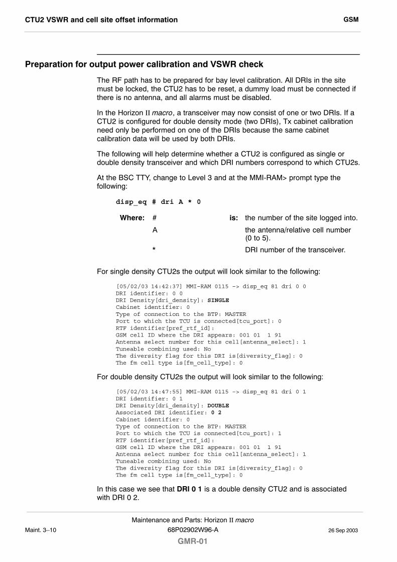
GSMCTU2 VSWR and cell site offset information
26 Sep 2003Maint. 3�10
Maintenance and Parts: Horizon II macro
GMR-0168P02902W96-A
Preparation for output power calibration and VSWR check
The RF path has to be prepared for bay level calibration. All DRIs in the sitemust be locked, the CTU2 has to be reset, a dummy load must be connected ifthere is no antenna, and all alarms must be disabled.
In the Horizon II macro, a transceiver may now consist of one or two DRIs. If aCTU2 is configured for double density mode (two DRIs), Tx cabinet calibrationneed only be performed on one of the DRIs because the same cabinetcalibration data will be used by both DRIs.
The following will help determine whether a CTU2 is configured as single ordouble density transceiver and which DRI numbers correspond to which CTU2s.
At the BSC TTY, change to Level 3 and at the MMI-RAM> prompt type thefollowing:
disp_eq # dri A * 0
Where: # is: the number of the site logged into.
A the antenna/relative cell number(0 to 5).
* DRI number of the transceiver.
For single density CTU2s the output will look similar to the following:
[05/02/03 14:42:37] MMI–RAM 0115 –> disp_eq 81 dri 0 0DRI identifier: 0 0DRI Density[dri_density]: SINGLECabinet identifier: 0Type of connection to the BTP: MASTERPort to which the TCU is connected[tcu_port]: 0RTF identifier[pref_rtf_id]: GSM cell ID where the DRI appears: 001 01 1 91Antenna select number for this cell[antenna_select]: 1Tuneable combining used: NoThe diversity flag for this DRI is[diversity_flag]: 0The fm cell type is[fm_cell_type]: 0
For double density CTU2s the output will look similar to the following:
[05/02/03 14:47:55] MMI–RAM 0115 –> disp_eq 81 dri 0 1DRI identifier: 0 1DRI Density[dri_density]: DOUBLEAssociated DRI identifier: 0 2Cabinet identifier: 0Type of connection to the BTP: MASTERPort to which the TCU is connected[tcu_port]: 1RTF identifier[pref_rtf_id]: GSM cell ID where the DRI appears: 001 01 1 91Antenna select number for this cell[antenna_select]: 1Tuneable combining used: NoThe diversity flag for this DRI is[diversity_flag]: 0The fm cell type is[fm_cell_type]: 0
In this case we see that DRI 0 1 is a double density CTU2 and is associatedwith DRI 0 2.
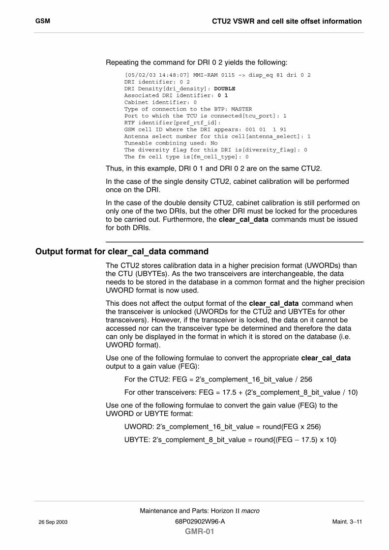
GSM CTU2 VSWR and cell site offset information
26 Sep 2003
Maintenance and Parts: Horizon II macro
68P02902W96-A
GMR-01Maint. 3�11
Repeating the command for DRI 0 2 yields the following:
[05/02/03 14:48:07] MMI–RAM 0115 –> disp_eq 81 dri 0 2DRI identifier: 0 2DRI Density[dri_density]: DOUBLEAssociated DRI identifier: 0 1Cabinet identifier: 0Type of connection to the BTP: MASTERPort to which the TCU is connected[tcu_port]: 1RTF identifier[pref_rtf_id]: GSM cell ID where the DRI appears: 001 01 1 91Antenna select number for this cell[antenna_select]: 1Tuneable combining used: NoThe diversity flag for this DRI is[diversity_flag]: 0The fm cell type is[fm_cell_type]: 0
Thus, in this example, DRI 0 1 and DRI 0 2 are on the same CTU2.
In the case of the single density CTU2, cabinet calibration will be performedonce on the DRI.
In the case of the double density CTU2, cabinet calibration is still performed ononly one of the two DRIs, but the other DRI must be locked for the proceduresto be carried out. Furthermore, the clear_cal_data commands must be issuedfor both DRIs.
Output format for clear_cal_data command
The CTU2 stores calibration data in a higher precision format (UWORDs) thanthe CTU (UBYTEs). As the two transceivers are interchangeable, the dataneeds to be stored in the database in a common format and the higher precisionUWORD format is now used.
This does not affect the output format of the clear_cal_data command whenthe transceiver is unlocked (UWORDs for the CTU2 and UBYTEs for othertransceivers). However, if the transceiver is locked, the data on it cannot beaccessed nor can the transceiver type be determined and therefore the datacan only be displayed in the format in which it is stored on the database (i.e.UWORD format).
Use one of the following formulae to convert the appropriate clear_cal_dataoutput to a gain value (FEG):
For the CTU2: FEG = 2�s_complement_16_bit_value / 256
For other transceivers: FEG = 17.5 + (2�s_complement_8_bit_value / 10)
Use one of the following formulae to convert the gain value (FEG) to theUWORD or UBYTE format:
UWORD: 2�s_complement_16_bit_value = round(FEG x 256)
UBYTE: 2�s_complement_8_bit_value = round{(FEG � 17.5) x 10}
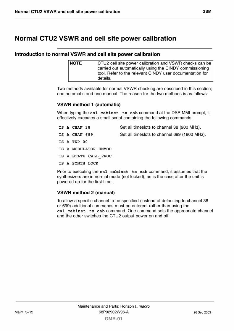
GSMNormal CTU2 VSWR and cell site power calibration
26 Sep 2003Maint. 3�12
Maintenance and Parts: Horizon II macro
GMR-0168P02902W96-A
Normal CTU2 VSWR and cell site power calibration
Introduction to normal VSWR and cell site power calibration
NOTE CTU2 cell site power calibration and VSWR checks can becarried out automatically using the CINDY commissioningtool. Refer to the relevant CINDY user documentation fordetails.
Two methods available for normal VSWR checking are described in this section;one automatic and one manual. The reason for the two methods is as follows:
VSWR method 1 (automatic)
When typing the cal_cabinet tx_cab command at the DSP MMI prompt, iteffectively executes a small script containing the following commands:
TS A CHAN 38 Set all timeslots to channel 38 (900 MHz).
TS A CHAN 699 Set all timeslots to channel 699 (1800 MHz).
TS A TXP 00
TS A MODULATOR UNMOD
TS A STATE CALL_PROC
TS A SYNTH LOCK
Prior to executing the cal_cabinet tx_cab command, it assumes that thesynthesizers are in normal mode (not locked), as is the case after the unit ispowered up for the first time.
VSWR method 2 (manual)
To allow a specific channel to be specified (instead of defaulting to channel 38or 699) additional commands must be entered, rather than using thecal_cabinet tx_cab command. One command sets the appropriate channeland the other switches the CTU2 output power on and off.
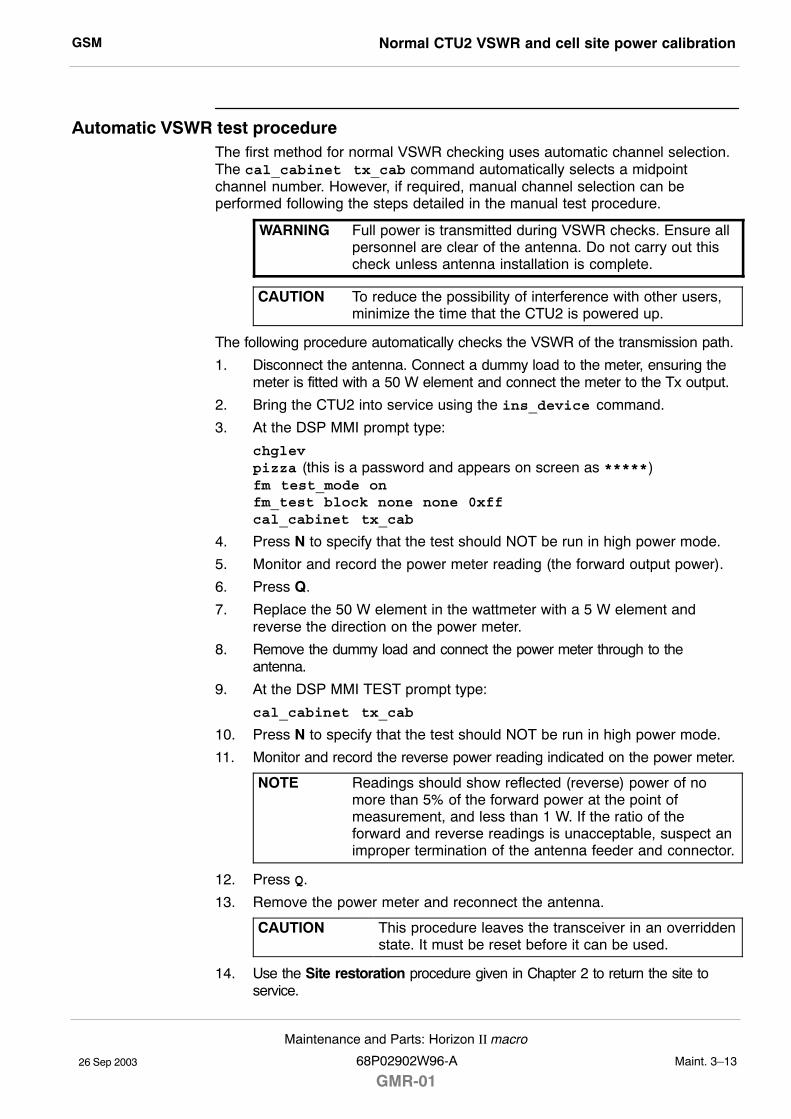
GSM Normal CTU2 VSWR and cell site power calibration
26 Sep 2003
Maintenance and Parts: Horizon II macro
68P02902W96-A
GMR-01Maint. 3�13
Automatic VSWR test procedureThe first method for normal VSWR checking uses automatic channel selection.The cal_cabinet tx_cab command automatically selects a midpointchannel number. However, if required, manual channel selection can beperformed following the steps detailed in the manual test procedure.
WARNING Full power is transmitted during VSWR checks. Ensure allpersonnel are clear of the antenna. Do not carry out thischeck unless antenna installation is complete.
CAUTION To reduce the possibility of interference with other users,minimize the time that the CTU2 is powered up.
The following procedure automatically checks the VSWR of the transmission path.
1. Disconnect the antenna. Connect a dummy load to the meter, ensuring themeter is fitted with a 50 W element and connect the meter to the Tx output.
2. Bring the CTU2 into service using the ins_device command.
3. At the DSP MMI prompt type:
chglevpizza (this is a password and appears on screen as *****)fm test_mode onfm_test block none none 0xffcal_cabinet tx_cab
4. Press N to specify that the test should NOT be run in high power mode.
5. Monitor and record the power meter reading (the forward output power).
6. Press Q.
7. Replace the 50 W element in the wattmeter with a 5 W element andreverse the direction on the power meter.
8. Remove the dummy load and connect the power meter through to theantenna.
9. At the DSP MMI TEST prompt type:
cal_cabinet tx_cab
10. Press N to specify that the test should NOT be run in high power mode.
11. Monitor and record the reverse power reading indicated on the power meter.
NOTE Readings should show reflected (reverse) power of nomore than 5% of the forward power at the point ofmeasurement, and less than 1 W. If the ratio of theforward and reverse readings is unacceptable, suspect animproper termination of the antenna feeder and connector.
12. Press Q.
13. Remove the power meter and reconnect the antenna.
CAUTION This procedure leaves the transceiver in an overriddenstate. It must be reset before it can be used.
14. Use the Site restoration procedure given in Chapter 2 to return the site toservice.
GSMNormal CTU2 VSWR and cell site power calibration
26 Sep 2003Maint. 3�14
Maintenance and Parts: Horizon II macro
GMR-0168P02902W96-A
Manual VSWR test procedure
WARNING Full power is transmitted during VSWR checks. Ensure allpersonnel are clear of the antenna. Do not carry out thischeck unless antenna installation is complete.
CAUTION To reduce the possibility of interference with other users,minimize the time that the CTU2 is powered up.
The second method for normal VSWR checking allows the manual selection of achannel.
VSWR forward power test
The following procedure is used to manually check the VSWR of thetransmission path through to the antenna.
1. Disconnect the antenna. Connect a dummy load to the power meter,ensuring the meter is fitted with a 50 W element and connect the meter tothe Tx output.
2. Bring the CTU2 into service using the ins_device command.
3. At the DSP MMI prompt type:
chglevpizza (this is a password and appears on screen as *****)fm test_mode onfm_test block none none 0xffts a state call_proc
4. Enter the following command:
ts a chan nnn
Where: a is: all timeslots (TS).
nnn the specified channel number.
5. To switch the power on, enter the following command:
ts a txp 0x00
Where: a is: all timeslots (TS).
00 maximum output power.
6. Monitor and record the power meter reading (the forward output power).
7. To switch the power off, enter the following command:
ts a txp 0xff
Where: a is: all timeslots (TS).
ff zero output power.
GSM Normal CTU2 VSWR and cell site power calibration
26 Sep 2003
Maintenance and Parts: Horizon II macro
68P02902W96-A
GMR-01Maint. 3�15
VSWR reverse power test
The following procedure is used to manually check the VSWR reverse power.
1. Replace the 50 W element in the power meter with a 5 W element andreverse the direction on the power meter.
2. Remove the dummy load and connect the power meter through to theantenna.
3. To switch the power on, enter:
ts a txp 0x00
4. Monitor and record the reverse power reading indicated on the powermeter.
NOTE Readings should show reflected (reverse) power of nomore than 5% of the forward power at the point ofmeasurement, and less than 1 W. If the ratio of theforward and reverse readings is unacceptable, suspect animproper termination of the antenna feeder and connector.
5. To switch the power off, enter:
ts a txp 0xff
Repeat the above forward and reverse power checks for the required number ofchannels.
When all channels have been checked, at the DSP MMI TEST prompt type:
ts a state active_standby
Remove the power meter and reconnect the antenna.
CAUTION This procedure leaves the transceiver in an overriddenstate. It must be reset before it can be used.
Use the Site restoration procedure given in Chapter 2 to return the site toservice.
GSMNormal CTU2 VSWR and cell site power calibration
26 Sep 2003Maint. 3�16
Maintenance and Parts: Horizon II macro
GMR-0168P02902W96-A
Tx output power calibration procedure
NOTE Calibration is not required unless the desired configurationis different to the shipped configuration.
The following procedure is used to calibrate CTU2 transmit output power:
1. Connect the 9-way to 9-way HIISC cable from the PC serial A port to theHIISC TTY port.
2. At the PC, start the terminal emulator program.
3. Lock all DRIs in the sector. At the HIISC TTY, change to Level 3 and at theMMI-RAM> prompt type:
lock_device # dri A * 0
Where: # is: the number of the site logged into.
A the antenna/relative cell number(0 to 5).
* DRI number of the transceiver.
NOTE Always lock the transceiver providing the BCCH last asthis prevents the BCCH being switched to alternatetransceivers.
4. Disconnect the antenna. Connect a dummy load to the power meter,ensuring the meter is fitted with a 50 W element. Connect the meter to theTx output.
5. Change to Level 3 and at the MMI-RAM> prompt type:
ins_device # dri A * 0
Where: # is: the number of the site logged into.
A the antenna/relative cell number(0 to 5).
* DRI number of the transceiver.
6. Connect a serial port on the PC to the TTY Interface port on the CTU2 tobe calibrated using the 9-way to 9-way DSP MMI/RSS cable.
If necessary, switch the 9-way to 9-way DSP MMI/RSS cable fromproviding RSS connectivity to providing DSP connectivity.
7. At the DSP MMI prompt type:
chglev
and then enter the following password:
pizza
8. Enter calibration test mode and disable alarms by typing the followingcommands:
cal_test_mode on
fm test_mode on
fm_test block none none 0xff
GSM Normal CTU2 VSWR and cell site power calibration
26 Sep 2003
Maintenance and Parts: Horizon II macro
68P02902W96-A
GMR-01Maint. 3�17
9. By default, Tx calibration is performed in the mode specified in thedatabase. To force Tx calibration in either single or double density modefor a transceiver, enter one of the following commands as required:
cal_config tx_cab_mode single
cal_config tx_cab_mode double
To reset Tx calibration to the mode specified in the database, enter thefollowing command:
cal_config tx_cab_mode database
10. Start the Tx cabinet calibration procedure by typing the followingcommand at the DSP MMI prompt:
cal_cabinet tx_cab
The following warning message will be displayed on the screen:WARNING! All attenuation is about to be removed. Please ensure that appropriate attenuation is attached to the CTU2 TX output.Press any key to continue
11. Check the connections to the antenna and then press ENTER.
For calibration in single density mode only, the following information andinstructions will be printed:High Power Mode is currently DISABLED (max_tx_bts is >= 0).High Power Mode will only be used if max_tx_bts databaseparameter is set to –1.If the current site database is accurate, you should runTX cabinet calibration in the same mode as the database.Press “H” to calibrate in High Power Mode,or press “N” to calibrate in Normal Power Mode.
NOTE The above message does not appear if thetransceiver is set to high power mode.
Press H or N as appropriate.
The following instructions will be displayed:Press U to increase power, D to decrease poweruntil the target output power is reached.Then press “Q” when finished.
12. Press U to increase output power or D to decrease output power until thereading on the power meter matches the target maximum power for thesector.
As the output power is adjusted, a message similar to the following will bedisplayed:Setting offset to = 0x13
13. Press Q when the desired output power level has been reached.
14. Store the new Tx cabinet calibration using the following DSP MMIcommand:
cal_store_1
After a few seconds delay (up to 16 seconds), the result of the datastorage is displayed on the screen in the format:cal_store_1PASSCTU2.carA.ts_0>
GSMNormal CTU2 VSWR and cell site power calibration
26 Sep 2003Maint. 3�18
Maintenance and Parts: Horizon II macro
GMR-0168P02902W96-A
15. After the data has been stored, connect the 9-way to 9-way HIISC cablefrom the PC serial A port to the HIISC MMI TTY port and enter thefollowing command to lock the CTU2 that has been calibrated:
lock_device # dri A * 0
Where: # is: the number of the site loggedinto.
A the antenna/relative cellnumber (0 to 5).
* DRI number on the transceiver.
16. Move the 9-way to 9-way DSP MMI/RSS cable to the CTU2 TTY port ofthe next CTU2 to be calibrated and repeat the procedure from step 4.
17. Remove the power meter and check that all antennas have beenreconnected.
18. Use the Site restoration procedure in Chapter 2 to return the site toservice.
Tx cabinet channel numbers and frequencies
The Tx cabinet channel numbers and frequencies for the Horizon II macro areas follows:
EGSM900: RF channel 23 939.6 MHz
DCS1800: RF channel 668 1836.4 MHz
GSM Checking the database equipage
26 Sep 2003
Maintenance and Parts: Horizon II macro
68P02902W96-A
GMR-01Maint. 3�19
Checking the database equipage
Introduction to checking the database
The database equipage checks determine what devices and functions havebeen equipped in the BSC/Horizon II macro database.
There are two stages to the procedure:
S Preparing for the test.
S Checking the database equipage.
Test equipment required
The following test equipment is required during the procedure:
S An IBM-compatible personal computer (PC).
S Terminal emulator software.
S A 9-way to 9-way cable (a diagram of this cable is provided inFigure Maint. 3-1 of the Test equipment, leads and plugs section).
CAUTION All test equipment and test leads must be calibratedannually by a recognized laboratory. Test equipment andtest leads must not be calibrated in the field.Do not optimize Motorola cellular base stations with testequipment that is beyond its calibration due date.Allow test equipment to warm up for 30 minutes beforeuse.
Commands used
The following commands are used during the procedure:
disp_site Displays the site number.
disp_equipment Displays the active equipment at a specified site.
Preparation for database checks
To prepare for the database equipage checks:
1. Ensure that the site is in call processing mode.
2. Connect the serial A port on the PC to the HIISC TTY port using the 9-wayto 9-way cable.
3. Start the terminal emulator program at the PC.
GSMChecking the database equipage
26 Sep 2003Maint. 3�20
Maintenance and Parts: Horizon II macro
GMR-0168P02902W96-A
Database equipage check procedure
To check the database for devices and functions:
1. At the CUST MMI prompt type:
disp_site
The following message (from the HIISC) is displayed:
current site is #
where # = the number of the site logged into.
2. At the CUST MMI prompt type:
disp_equipment #
where # = the number of the site logged into.
A complete list of the equipment and functions in the database isdisplayed. For example:
CSFPBTPDRIDRIDRIDRIDRIDRIDRIDRIDRIDRIDRIDRIMSIMMSMMSMMSMMSMMSMMSRSLGCLKEASCABSITEPATHRTFRTFRTFRTFRTFRTFRTFRTFRTFRTFRTFRTF
0 0 00 0 00 0 00 1 00 2 00 3 01 0 01 1 01 2 01 3 02 0 02 1 02 2 02 3 00 0 00 0 00 1 00 2 00 3 00 4 00 5 00 0 00 0 00 0 00 0 00 0 00 0 00 0 00 1 00 2 00 3 01 0 01 1 01 2 01 3 02 0 02 1 02 2 02 3 0
(0 1 0)(0 0 0)(0 3 0)(0 2 0)(1 1 0)(1 0 0)(1 3 0)(1 2 0)(2 1 0)(2 0 0)(2 3 0)(2 2 0)
GSM Checking the database equipage
26 Sep 2003
Maintenance and Parts: Horizon II macro
68P02902W96-A
GMR-01Maint. 3�21
3. To check the MSI configuration at the CUST MMI prompt type:
disp_equipment # MSI 0 0
Where: # = site number.
A message similar to the following example is displayed:
MSI identifier: 0MSI type [msi_type]: NIU2
GSMChecking the E1/T1 link
26 Sep 2003Maint. 3�22
Maintenance and Parts: Horizon II macro
GMR-0168P02902W96-A
Checking the E1/T1 link
Introduction to checking the E1/T1 link
The E1/T1 link checks verify the integrity of the links back to the BSC/MSC.
There are two stages to the procedure:
S Preparing for the test.
S Checking the E1/T1 link.
Test equipment required
The E1/T1 link checks require the following test equipment:
S An IBM compatible personal computer (PC).
S Terminal emulator software.
S A 9-way to 9-way cable (a diagram of this cable is provided inFigure Maint. 3-1 of the Test equipment, leads and plugs section).
CAUTION All test equipment and test leads must be calibratedannually by a recognized laboratory. Test equipment andtest leads must not be calibrated in the field.Do not optimize Motorola cellular base stations with testequipment that is beyond its calibration due date.Allow test equipment to warm up for 30 minutes beforeuse.
Commands used
The following command is used to carry out the procedure:
state Displays the status of specified devices or functions.
Preparation for the E1/T1 link check
The following procedure is used to set up the equipment to check the E1/T1links:
1. Make sure the site is in call processing mode.
2. Connect the serial A port on the PC to the HIISC TTY port using the 9-wayto 9-way cable.
3. Start the terminal emulator program at the PC.
The system and the hardware are set up to check the E1/T1 links.
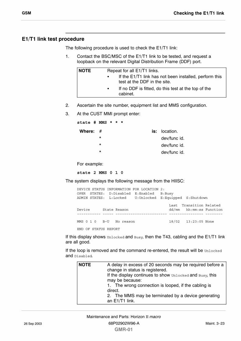
GSM Checking the E1/T1 link
26 Sep 2003
Maintenance and Parts: Horizon II macro
68P02902W96-A
GMR-01Maint. 3�23
E1/T1 link test procedure
The following procedure is used to check the E1/T1 link:
1. Contact the BSC/MSC of the E1/T1 link to be tested, and request aloopback on the relevant Digital Distribution Frame (DDF) port.
NOTE Repeat for all E1/T1 links.S If the E1/T1 link has not been installed, perform this
test at the DDF in the site.
S If no DDF is fitted, do this test at the top of thecabinet.
2. Ascertain the site number, equipment list and MMS configuration.
3. At the CUST MMI prompt enter:
state # MMS * * *
Where: # is: location.
* dev/func id.
* dev/func id.
* dev/func id.
For example:
state 2 MMS 0 1 0
The system displays the following message from the HIISC:
DEVICE STATUS INFORMATION FOR LOCATION 2:OPER STATES: D:Disabled E:Enabled B:BusyADMIN STATES: L:Locked U:Unlocked E:Equipped S:Shutdown
Last Transition RelatedDevice State Reason dd/mm hh:mm:ss Function––––––––––– ––––– –––––––––––––––––––––––– –––––––––––––––– ––––––––
MMS 0 1 0 B–U No reason 18/02 13:23:05 None
END OF STATUS REPORT
If this display shows Unlocked and Busy, then the T43, cabling and the E1/T1 linkare all good.
If the loop is removed and the command re-entered, the result will be Unlockedand Disabled.
NOTE A delay in excess of 20 seconds may be required before achange in status is registered.If the display continues to show Unlocked and Busy, thismay be because:1. The wrong connection is looped, if the cabling isdirect.2. The MMS may be terminated by a device generatingan E1/T1 link.
GSMChecking PIX connections and alarms
26 Sep 2003Maint. 3�24
Maintenance and Parts: Horizon II macro
GMR-0168P02902W96-A
Checking PIX connections and alarms
Introduction to checking the PIX connections and alarms
The alarm tests check the serial connections and alarm status.
There are two stages to the procedure:
S Preparing for the test.
S Testing the PIX connections using the database external alarm system(EAS).
Test equipment required
The serial and alarm tests require the following test equipment:
S An IBM compatible personal computer (PC).
S Terminal emulator software.
S A 9-way to 9-way cable (a diagram of this cable is provided inFigure Maint. 3-1 of the Test equipment, leads and plugs section.
CAUTION All test equipment and test leads must be calibratedannually by a recognized laboratory. Test equipment andtest leads must not be calibrated in the field.Do not optimize Motorola cellular base stations with testequipment that is beyond its calibration due date.Allow test equipment to warm up for 30 minutes beforeuse.
Commands used
The following commands are used to test the PIX connections:
alarm_mode <site number> on Enables alarm reporting for aspecified site.
disp_act_alarm <site number> Displays active alarms at the specifiedsite.
equip <site number> EAS Equip the external alarm system atthe specified site.
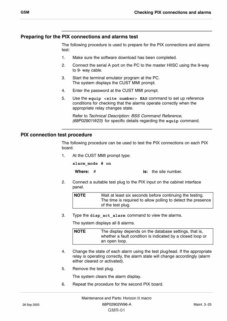
GSM Checking PIX connections and alarms
26 Sep 2003
Maintenance and Parts: Horizon II macro
68P02902W96-A
GMR-01Maint. 3�25
Preparing for the PIX connections and alarms test
The following procedure is used to prepare for the PIX connections and alarmstest:
1. Make sure the software download has been completed.
2. Connect the serial A port on the PC to the master HIISC using the 9-wayto 9- way cable.
3. Start the terminal emulator program at the PC.The system displays the CUST MMI prompt.
4. Enter the password at the CUST MMI prompt.
5. Use the equip <site number> EAS command to set up referenceconditions for checking that the alarms operate correctly when theappropriate relay changes state.
Refer to Technical Description: BSS Command Reference,(68P02901W23) for specific details regarding the equip command.
PIX connection test procedure
The following procedure can be used to test the PIX connections on each PIXboard.
1. At the CUST MMI prompt type:
alarm_mode # on
Where: # is: the site number.
2. Connect a suitable test plug to the PIX input on the cabinet interfacepanel.
NOTE Wait at least six seconds before continuing the testing.The time is required to allow polling to detect the presenceof the test plug.
3. Type the disp_act_alarm command to view the alarms.
The system displays all 8 alarms.
NOTE The display depends on the database settings, that is,whether a fault condition is indicated by a closed loop oran open loop.
4. Change the state of each alarm using the test plug/lead. If the appropriaterelay is operating correctly, the alarm state will change accordingly (alarmeither cleared or activated).
5. Remove the test plug.
The system clears the alarm display.
6. Repeat the procedure for the second PIX board.

GSMChecking PIX connections and alarms
26 Sep 2003Maint. 3�26
Maintenance and Parts: Horizon II macro
GMR-0168P02902W96-A
26 Sep 2003
Maintenance and Parts: Horizon II macro
68P02902W96-A
GMR-01Maint. 4�1
Chapter 4
Parts information for
Horizon II macro

GSM
26 Sep 2003Maint. 4�2
Maintenance and Parts: Horizon II macro
GMR-0168P02902W96-A
GSM Horizon II macro parts lists
26 Sep 2003
Maintenance and Parts: Horizon II macro
68P02902W96-A
GMR-01Maint. 4�3
Horizon II macro parts lists
Introduction to Horizon II macro parts list
In the parts lists contained in this chapter, each item consists of a locationnumber (related to the associated diagram), description, and an order number.The order number uniquely identifies the required component. Somecomponents may be used in other equipment in addition to Horizon II macro.
FRU items
The majority of items on the parts list are field replaceable units (FRUs). It is notintended to supply sub-units of these spares.
Ordering method
Contact the local Motorola office for ordering information, including cost anddelivery.
If an item in the parts list is marked TBA, this means that the part number for theitem was not available at the time of publication of this manual.
NOTE Motorola reserves the right to change the design of theproduct without notice. The information provided in thischapter is intended as a guide. If the customer requiresthe latest information, then consult the Motorola localoffice who will be able to check on the web and confirmthe current situation.Some items, for example PSUs, are produced by differentmanufacturers, and so a replacement may appear slightlydifferent to the item it is replacing. All items bearing thesame order number, regardless of manufacturer, are fullycompatible.
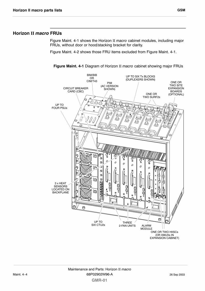
GSMHorizon II macro parts lists
26 Sep 2003Maint. 4�4
Maintenance and Parts: Horizon II macro
GMR-0168P02902W96-A
Horizon II macro FRUs
Figure Maint. 4-1 shows the Horizon II macro cabinet modules, including majorFRUs, without door or hood/stacking bracket for clarity.
Figure Maint. 4-2 shows those FRU items excluded from Figure Maint. 4-1.
Figure Maint. 4-1 Diagram of Horizon II macro cabinet showing major FRUs
CIRCUIT BREAKERCARD (CBC)
ONE OR TWO HIISCs(OR XMUXs IN
EXPANSION CABINET)
ALARMMODULE
THREE2-FAN UNITS
UP TOSIX CTU2s
UP TO SIX Tx BLOCKS(DUPLEXERS SHOWN)
ONE ORTWO SITE
EXPANSIONBOARDS
(OPTIONAL)
3 x HEATSENSORS
LOCATED ONBACKPLANE
UP TOFOUR PSUs
BIM/BIBOR
CIM/T43
ONE ORTWO SURF2s
PIM(AC VERSION
SHOWN)
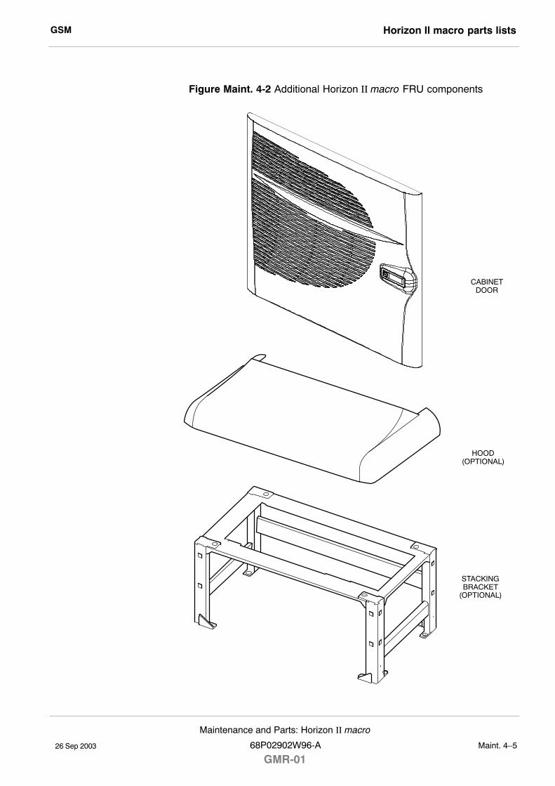
GSM Horizon II macro parts lists
26 Sep 2003
Maintenance and Parts: Horizon II macro
68P02902W96-A
GMR-01Maint. 4�5
Figure Maint. 4-2 Additional Horizon II macro FRU components
CABINETDOOR
HOOD(OPTIONAL)
STACKINGBRACKET
(OPTIONAL)
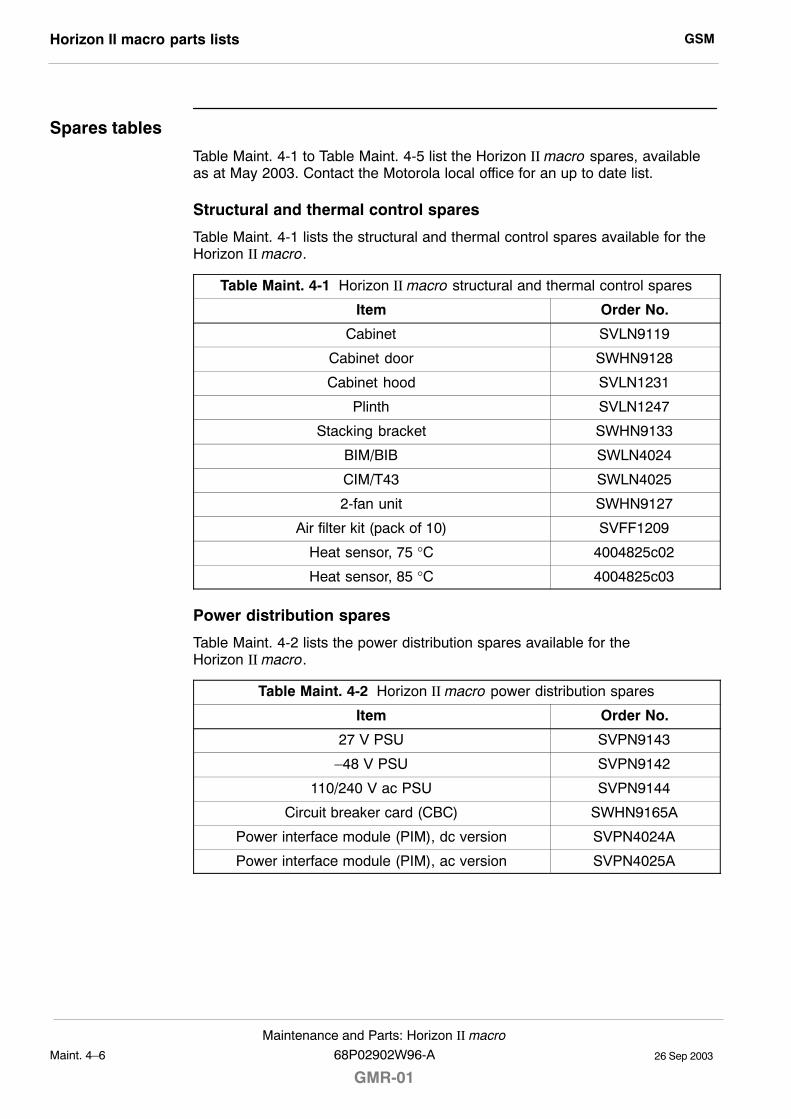
GSMHorizon II macro parts lists
26 Sep 2003Maint. 4�6
Maintenance and Parts: Horizon II macro
GMR-0168P02902W96-A
Spares tables
Table Maint. 4-1 to Table Maint. 4-5 list the Horizon II macro spares, availableas at May 2003. Contact the Motorola local office for an up to date list.
Structural and thermal control spares
Table Maint. 4-1 lists the structural and thermal control spares available for theHorizon II macro.
Table Maint. 4-1 Horizon II macro structural and thermal control spares
Item Order No.
Cabinet SVLN9119
Cabinet door SWHN9128
Cabinet hood SVLN1231
Plinth SVLN1247
Stacking bracket SWHN9133
BIM/BIB SWLN4024
CIM/T43 SWLN4025
2-fan unit SWHN9127
Air filter kit (pack of 10) SVFF1209
Heat sensor, 75 °C 4004825c02
Heat sensor, 85 °C 4004825c03
Power distribution spares
Table Maint. 4-2 lists the power distribution spares available for theHorizon II macro.
Table Maint. 4-2 Horizon II macro power distribution spares
Item Order No.
27 V PSU SVPN9143
�48 V PSU SVPN9142
110/240 V ac PSU SVPN9144
Circuit breaker card (CBC) SWHN9165A
Power interface module (PIM), dc version SVPN4024A
Power interface module (PIM), ac version SVPN4025A
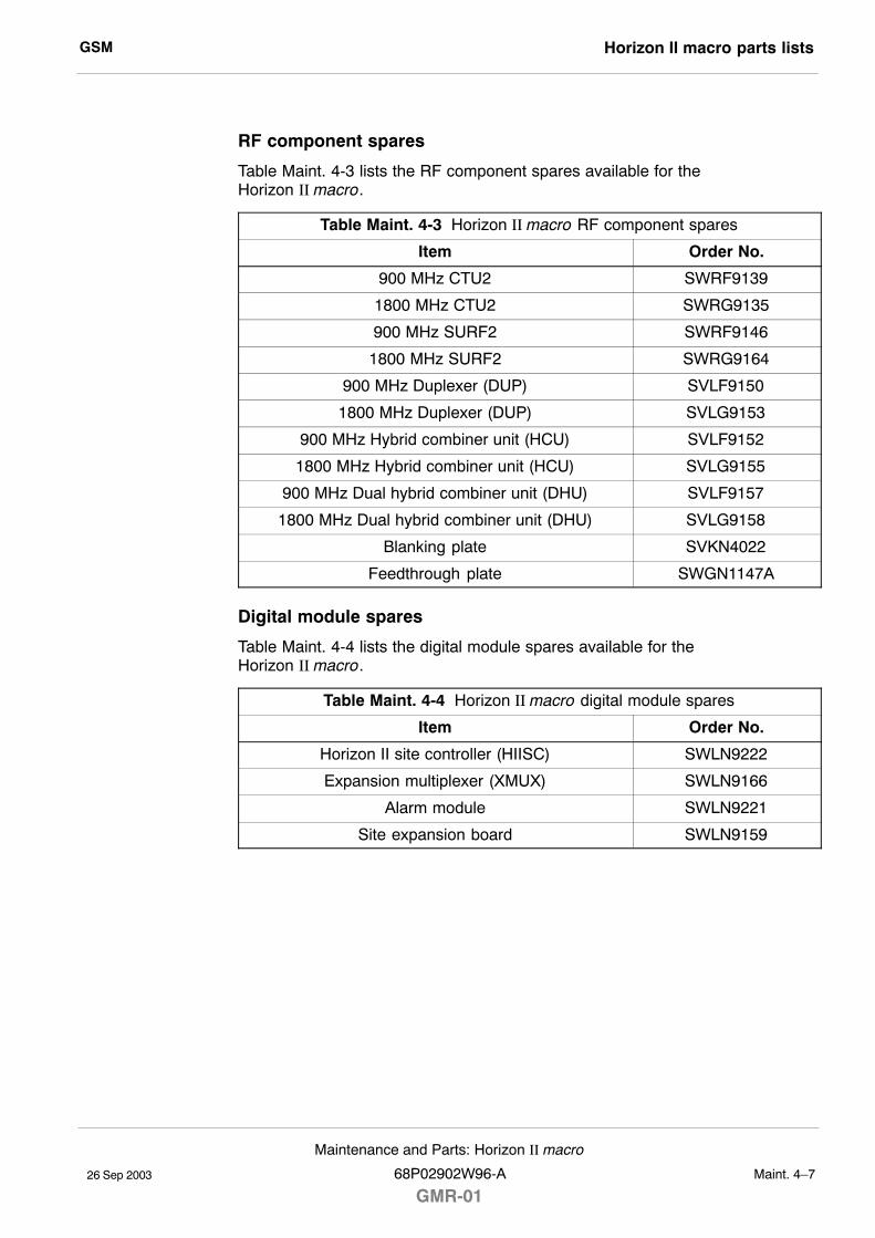
GSM Horizon II macro parts lists
26 Sep 2003
Maintenance and Parts: Horizon II macro
68P02902W96-A
GMR-01Maint. 4�7
RF component spares
Table Maint. 4-3 lists the RF component spares available for theHorizon II macro.
Table Maint. 4-3 Horizon II macro RF component spares
Item Order No.
900 MHz CTU2 SWRF9139
1800 MHz CTU2 SWRG9135
900 MHz SURF2 SWRF9146
1800 MHz SURF2 SWRG9164
900 MHz Duplexer (DUP) SVLF9150
1800 MHz Duplexer (DUP) SVLG9153
900 MHz Hybrid combiner unit (HCU) SVLF9152
1800 MHz Hybrid combiner unit (HCU) SVLG9155
900 MHz Dual hybrid combiner unit (DHU) SVLF9157
1800 MHz Dual hybrid combiner unit (DHU) SVLG9158
Blanking plate SVKN4022
Feedthrough plate SWGN1147A
Digital module spares
Table Maint. 4-4 lists the digital module spares available for theHorizon II macro.
Table Maint. 4-4 Horizon II macro digital module spares
Item Order No.
Horizon II site controller (HIISC) SWLN9222
Expansion multiplexer (XMUX) SWLN9166
Alarm module SWLN9221
Site expansion board SWLN9159
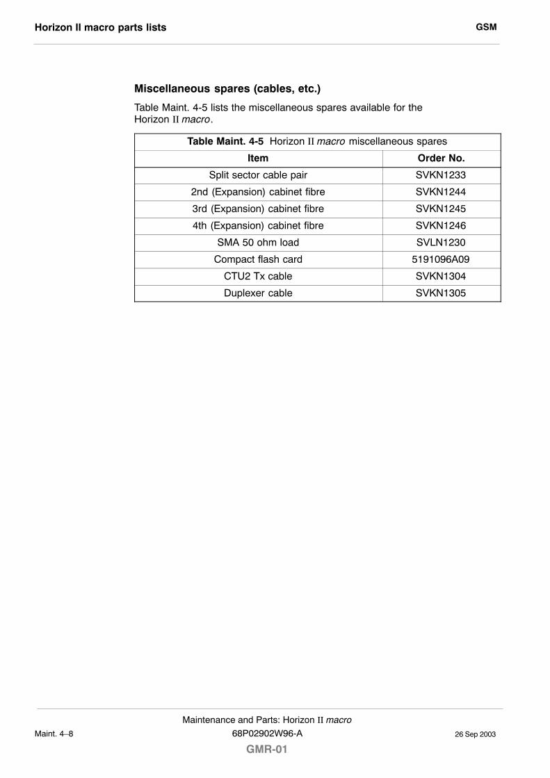
GSMHorizon II macro parts lists
26 Sep 2003Maint. 4�8
Maintenance and Parts: Horizon II macro
GMR-0168P02902W96-A
Miscellaneous spares (cables, etc.)
Table Maint. 4-5 lists the miscellaneous spares available for theHorizon II macro.
Table Maint. 4-5 Horizon II macro miscellaneous spares
Item Order No.
Split sector cable pair SVKN1233
2nd (Expansion) cabinet fibre SVKN1244
3rd (Expansion) cabinet fibre SVKN1245
4th (Expansion) cabinet fibre SVKN1246
SMA 50 ohm load SVLN1230
Compact flash card 5191096A09
CTU2 Tx cable SVKN1304
Duplexer cable SVKN1305

26 Sep 2003
Service Manual: Horizon II macro68P02902W96-A
GMR-01 I�1
Index

GSM
26 Sep 2003 I�2Service Manual: Horizon II macro
GMR-0168P02902W96-A
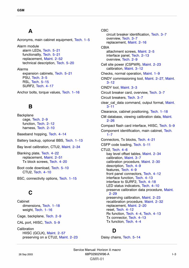
GSM
26 Sep 2003
Service Manual: Horizon II macro68P02902W96-A
GMR-01 I�3
AAcronyms, main cabinet equipment, Tech. 1�5
Alarm modulealarm LEDs, Tech. 5�21functionality, Tech. 5�21replacement, Maint. 2�52technical description, Tech. 5�20
Alarmsexpansion cabinets, Tech. 5�21PSU, Tech. 3�5RSL, Tech. 5�15SURF2, Tech. 4�17
Anchor bolts, torque values, Tech. 1�16
BBackplane
cage, Tech. 2�9function, Tech. 2�12harness, Tech. 2�10
Baseband hopping, Tech. 4�14
Battery backup, optional BBS, Tech. 1�13
Bay level calibration, CTU2, Maint. 2�34
Blanking plate, Tech. 4�22replacement, Maint. 2�51Tx block screws, Tech. 4�20
Boot code download, Tech. 5�10CTU2, Tech. 4�10
BSC, connectivity options, Tech. 1�15
CCabinet
dimensions, Tech. 1�18weight, Tech. 1�16
Cage, backplane, Tech. 2�9
CAL port, HIISC, Tech. 5�9
CalibrationHIISC (GCLK), Maint. 2�57preserving on a CTU2, Maint. 2�23
CBCcircuit breaker identification, Tech. 3�7overview, Tech. 3�7replacement, Maint. 2�16
CBIAattachment screws, Maint. 2�5interface panel, Tech. 2�13overview, Tech. 2�9
Cell site power (CSPWR), Maint. 2�23calibration, Maint. 3�12
Checks, normal operation, Maint. 1�9CINDY commissioning tool, Maint. 2�27, Maint.
3�12CINDY tool, Maint. 3�3Circuit breaker card, overview, Tech. 3�7Circuit breakers, Tech. 3�7clear_cal_data command, output format, Maint.
3�11Clearance, cabinet positioning, Tech. 1�18
CM database, viewing calibration data, Maint.2�26
Compact flash card interface, HIISC, Tech. 5�9Component identification, main cabinet, Tech.
1�7Connectors, Tx blocks, Tech. 4�21CSFP code loading, Tech. 5�11CTU2, Tech. 4�6
bay level offset tables, Maint. 2�34calibration, Maint. 3�7calibration procedure, Maint. 2�30description, Tech. 4�9features, Tech. 4�9front panel connectors, Tech. 4�12interface function, Tech. 4�13interface to SURF2, Tech. 4�18LED status indicators, Tech. 4�10preserve calibration data procedure, Maint.
2�29preserving calibration, Maint. 2�23recalibration procedure, Maint. 2�32replacement, Maint. 2�20reset, Tech. 4�12Rx function, Tech. 4�4, Tech. 4�13Tx connector, Tech. 4�13Tx function, Tech. 4�4
DDaisy chains, Tech. 5�14
GSM
26 Sep 2003 I�4Service Manual: Horizon II macro
GMR-0168P02902W96-A
Database equipage, checking, Maint. 3�19
DHU, replacement, Maint. 2�51
Digital modules, Tech. 5�3locations, Tech. 5�4
Dimensions, cabinet, Tech. 1�16, Tech. 1�18
Diversity, Tech. 4�19
Door, Tech. 2�16alarm switch, Tech. 3�7locking angles, Maint. 1�5operation, Maint. 1�5replacement, Maint. 2�6
Dual hybrid combiner unit (DHU), technicaldescription, Tech. 4�28
Duplexer, technical description, Tech. 4�24
Duplexing, Tech. 4�5
EE1, framing options, Tech. 5�14
E1/T1 link, checking, Maint. 3�22
EMC, containment, Maint. 2�51
Expansion cabinet, Tech. 5�18
Expansion cabinets, alarm transmission, Tech.5�21
FFan unit, replacement, Maint. 2�12
Fansheat control, Tech. 2�14temperature control, Tech. 2�15
featurereferences, 3tag format, 3
Feedthrough plate, Tech. 4�23replacement, Maint. 2�51Tx block screws, Tech. 4�20
FMUX, function, Tech. 5�18
Frequency band characteristics, Tech. 1�17
Frequency hopping, Tech. 1�17description, Tech. 4�14
FRU list, Maint. 2�3
GGCLK, calibration, Maint. 2�57
HHarness, backplane, Tech. 2�10
HCU, replacement, Maint. 2�51
Heat control, cabinet, PSUs, CTU2s, Tech.2�14
Heat sensorsdescription, Tech. 2�14replacement, Maint. 2�8
HIISCcode loading, Tech. 5�11front panel interfaces, Tech. 5�9front panel LEDs, Tech. 5�10internal architecture, Tech. 5�12link to redundant HIISC, Tech. 5�8redundancy testing, Maint. 2�55replacement, Maint. 2�52technical description, Tech. 5�7
HIISC (GCLK), calibration, Maint. 2�57
Hood, Tech. 2�17removal, Maint. 1�5replacement, Maint. 2�9
Horizonmacrocomponent comparison, Tech. 1�11connecting SURF to CTU2, Tech. 4�19Horizon II macro compatibility, Tech. 1�10
Hybrid combiner unit (HCU), technicaldescription, Tech. 4�26
Hybrid Combining Unit, Tx block screws, Tech.4�20
IInterface panel, As part of CBIA, Tech. 2�13
Interfaces, HIISC front panel, Tech. 5�9
LLAPD links, RSL configuration and control,
Tech. 5�15
LED indicators, transceiver, Tech. 4�10
Line interface module, Tech. 5�12
GSM
26 Sep 2003
Service Manual: Horizon II macro68P02902W96-A
GMR-01 I�5
LIU, Tech. 5�13timing extraction, Tech. 5�14
Loopback, RF test, Tech. 4�7
M
M�Cell6, Horizon II macro compatibility, Tech.1�10
Maintenance, routine maintenance schedule,Maint. 1�4
Master site controller, Horizonmacro or M�Cell6,Tech. 1�10
N
Names, main cabinet equipment, Tech. 1�5
NIU, control processor, Tech. 5�13
P
Parts, ordering, Maint. 4�3
PIM, replacement, Maint. 2�14
PIX, test lead connections, Maint. 3�6
PIX alarms, checking, Maint. 3�24
PIX outputs, HIISC, Tech. 5�10
Powerconsumption, Tech. 1�13supply requirements, Tech. 1�13
Power interface module (PIM), Tech. 2�13
Power supplies, location, Tech. 3�3
Power supply unit, technical information, Tech.3�4
Preserve CTU2 calibration data feature, Maint.2�28
PSUalarms, Tech. 3�5front panel LEDs, Tech. 3�6replacement, Maint. 2�18types, Tech. 3�4
RRedundancy, Tech. 5�19
digital modules, Tech. 5�5
Reporting faulty devices, Maint. 1�3
Reset, CTU2, Tech. 4�12
RFloopback test, Tech. 4�7output power, Tech. 1�14receive hardware, Tech. 4�4transmit hardware, Tech. 4�4
RF connections, torque values, Tech. 1�16
RF equipment, overview, Tech. 4�3
RF overview, Tech. 4�6
RSLalarms, Tech. 5�15configuration and control, Tech. 5�15
RSL termination, NIU control processor, Tech.5�13
SSensitivity, Rx performance, Tech. 1�15
Site control processor, HIISC, Tech. 5�13
Site expansion board, technical description,Tech. 5�19
Site expansion board, replacement, Maint. 2�52
SMA connector, CTU2, Tech. 4�13
Software requirements, Tech. 1�12
Span, type selection, Tech. 5�14
Span alarms, Tech. 5�15
Spares, table, Maint. 4�6
Specifications, Tech. 1�12
Stacking bracketdescription, Tech. 2�18replacement, Maint. 2�10
Structural considerations, Tech. 1�18
SURF2, Tech. 4�6description, Tech. 4�15installing a replacement module, Maint. 2�47interface to CTU2, Tech. 4�18removal procedure, Maint. 2�46replacement, Maint. 2�45
GSM
26 Sep 2003 I�6Service Manual: Horizon II macro
GMR-0168P02902W96-A
SURF2 harness, components, Tech. 2�6
Synthesizer hopping, Tech. 4�14
T
T1, framing options, Tech. 5�14
Temperature, environmental limits, Tech. 1�12
Temperature controlfan unit, Tech. 2�15sensors, Tech. 2�14
Test leads, verification, Maint. 3�5
Top panel, description, Tech. 2�8
Torque values, Maint. 2�4general, Tech. 1�16
Transceiver, CTU2 description, Tech. 4�9
TSI, Tech. 5�13
TTY MMI interface, HIISC, Tech. 5�9
TTY port, CTU2, Tech. 4�12
Tx block, Tech. 4�6connectors, Tech. 4�21fitting a replacement module, Maint. 2�51replacement, Maint. 2�48screw retention, Tech. 4�20types, Tech. 4�20
Type approval, Tech. 1�12
VVerification procedures, Maint. 3�3
VSWR, checking, Maint. 3�12
VSWR monitor, Tech. 4�24
VSWR monitoring, Tech. 4�7
WWeight, cabinet, Tech. 1�16
XXMUX
functionality on HIISC, Tech. 5�16replacement, Maint. 2�52technical description, Tech. 5�17