Service Manual - hoshizaki.com · • Do not use an appliance with a damaged power cord. The power...
57
Service Manual Number: F111-1006 Issued: 03-15-2018 hoshizakiamerica.com Models KM-230BAJ KM-300BAJ, BWJ Self-Contained Crescent Cuber
Transcript of Service Manual - hoshizaki.com · • Do not use an appliance with a damaged power cord. The power...
Service Manual
Number: F111-1006Issued: 03-15-2018hoshizakiamerica.com
ModelsKM-230BAJKM-300BAJ, BWJ
Self-Contained Crescent Cuber
1
WARNINGOnly qualified service technicians should install and service the appliance. To obtain the name and phone number of your local Hoshizaki Certified Service Representative, visit www.hoshizaki.com. No service should be undertaken until the technician has thoroughly read this Service Manual. Failure to service and maintain the appliance in accordance with this manual will adversely affect safety, performance, component life, and warranty coverage and may result in costly water damage. Proper installation is the responsibility of the installer. Product failure or property damage due to improper installation is not covered under warranty.
Hoshizaki provides this manual primarily to assist qualified service technicians in the maintenance and service of the product.
Should the reader have any questions or concerns which have not been satisfactorily addressed, please call, send an e-mail message, or write to the Hoshizaki Technical Support Department for assistance.
Phone: 1-800-233-1940; (770) 487-2331Fax: 1-800-843-1056; (770) 487-3360
E-mail: [email protected]
618 Highway 74 SouthPeachtree City, GA 30269Attn: Hoshizaki Technical Support Department
Web Site: www.hoshizaki.com
NOTE: To expedite assistance, all correspondence/communication MUST include the following information:
• Model Number
• Serial Number
• Complete and detailed explanation of the problem.
2
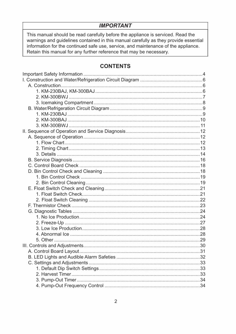
IMPORTANTThis manual should be read carefully before the appliance is serviced. Read the warnings and guidelines contained in this manual carefully as they provide essential information for the continued safe use, service, and maintenance of the appliance. Retain this manual for any further reference that may be necessary.
CONTENTSImportant Safety Information ..........................................................................................4I. Construction and Water/Refrigeration Circuit Diagram ...............................................6
A. Construction ...........................................................................................................61. KM-230BAJ, KM-300BAJ .................................................................................62. KM-300BWJ .....................................................................................................73. Icemaking Compartment ..................................................................................8
B. Water/Refrigeration Circuit Diagram ......................................................................91. KM-230BAJ ......................................................................................................92. KM-300BAJ ....................................................................................................103. KM-300BWJ ...................................................................................................11
II. Sequence of Operation and Service Diagnosis ........................................................12A. Sequence of Operation ........................................................................................12
1. Flow Chart ......................................................................................................122. Timing Chart ...................................................................................................133. Details ............................................................................................................14
B. Service Diagnosis ................................................................................................16C. Control Board Check ...........................................................................................18D. Bin Control Check and Cleaning .........................................................................18
1. Bin Control Check ..........................................................................................192. Bin Control Cleaning ......................................................................................19
E. Float Switch Check and Cleaning ........................................................................211. Float Switch Check.........................................................................................212. Float Switch Cleaning ....................................................................................22
F. Thermistor Check .................................................................................................23G. Diagnostic Tables ................................................................................................24
1. No Ice Production ...........................................................................................242. Freeze-Up ......................................................................................................273. Low Ice Production .........................................................................................284. Abnormal Ice ..................................................................................................285. Other ..............................................................................................................29
III. Controls and Adjustments........................................................................................30A. Control Board Layout ...........................................................................................31B. LED Lights and Audible Alarm Safeties ...............................................................32C. Settings and Adjustments ....................................................................................33
1. Default Dip Switch Settings ............................................................................332. Harvest Timer .................................................................................................333. Pump-Out Timer .............................................................................................344. Pump-Out Frequency Control ........................................................................34
3
5. Harvest Pump Timer.......................................................................................356. Freeze Timer ..................................................................................................357. Pump-Out/Drain Selector ...............................................................................368. Harvest Promotion Control .............................................................................369. Refill Counter .................................................................................................36
10. Harvest Completion Detection Control ...........................................................3611. Overfreeze Detection Control .........................................................................3712. Anti-Slush Control ...........................................................................................3713. Control Board Replacement ...........................................................................38
D. Switches ..............................................................................................................381. Control Switch ................................................................................................382. Service Switch ................................................................................................38
IV. Refrigeration Circuit and Component Service Information ......................................40A. Refrigeration Circuit Service Information .............................................................40
1. Refrigerant Recovery .....................................................................................412. Brazing ...........................................................................................................413. Evacuation and Recharge (R-404A) ..............................................................41
B. Component Service Information ..........................................................................42C. Water Tank ...........................................................................................................43D. Separator .............................................................................................................44E. Door .....................................................................................................................45F. Adjustment of Water Regulating Valve (Water-Cooled Model) .............................46
V. Maintenance .............................................................................................................47A. Maintenance Schedule ........................................................................................47
VI. Preparing the Appliance for Periods of Non-Use ....................................................48VII. Disposal .................................................................................................................49VIII. Technical Information ............................................................................................50
A. Specification Data ................................................................................................501. KM-230BAJ ....................................................................................................502. KM-300BAJ ....................................................................................................513. KM-300BWJ ...................................................................................................52
B. Performance Data ................................................................................................531. KM-230BAJ ....................................................................................................532. KM-300BAJ ....................................................................................................543. KM-300BWJ ...................................................................................................55
C. Wiring Diagram ....................................................................................................56
4
Important Safety InformationThroughout this manual, notices appear to bring your attention to situations which couldresult in death, serious injury, damage to the appliance, or damage to property.
WARNING Indicates a hazardous situation which could result in death or serious injury.
NOTICE Indicates a situation which could result in damage to the appliance or property.
IMPORTANT Indicates important information about the installation, use, and care of the appliance.
WARNINGThe appliance should be destined only to the use for which it has been expressly conceived. Any other use should be considered improper and therefore dangerous. The manufacturer cannot be held responsible for injury or damage resulting from improper, incorrect, and unreasonable use. Failure to service and maintain the appliance in accordance with this manual will adversely affect safety, performance, component life, and warranty coverage and may result in costly water damage.To reduce the risk of death, electric shock, serious injury, or fire, follow basic precautions including the following:• Only qualified service technicians should install and service the appliance.• The appliance must be installed in accordance with applicable national, state, and
local codes and regulations.• The appliance requires an independent power supply of proper capacity. See
the nameplate for electrical specifications. Failure to use an independent power supply of proper capacity can result in a tripped breaker, blown fuse, damage to existing wiring, or component failure. This could lead to heat generation or fire.
• THE APPLIANCE MUST BE GROUNDED: The appliance is equipped with a NEMA 5-15 three-prong grounding plug to reduce the risk of potential shock hazards. It must be plugged into a properly grounded, independent 3-prong wall outlet. If the outlet is a 2-prong outlet, it is your personal responsibility to have a qualified electrician replace it with a properly grounded, independent 3-prong wall outlet. Do not remove the ground prong from the plug and do not use an adapter plug. Failure to properly ground the appliance could result in death or serious injury.
• Do not use an extension cord.• To reduce the risk of electric shock, do not touch the control switch, service switch,
or plug with damp hands. Make sure the control switch is in the "OFF" position before plugging in or unplugging the appliance.
• Do not use an appliance with a damaged power cord. The power cord should not be altered, jerked, bundled, weighed down, pinched, or tangled. Such actions could result in electric shock or fire. To unplug the appliance, be sure to pull the plug, not the cord, and do not jerk the cord.
• Do not make any alterations to the appliance. Alterations could result in electric shock, injury, fire, or damage to the appliance.
5
WARNING, continued• The appliance is not intended for use by persons (including children) with reduced
physical, sensory, or mental capabilities, or lack of experience and knowledge, unless they have been given supervision or instruction concerning use of the appliance by a person responsible for their safety.
• Young children should be properly supervised around the appliance.• Do not climb, stand, or hang on the appliance or appliance door or allow children
or animals to do so. Serious injury could occur or the appliance could be damaged.
• Be careful not to pinch fingers when opening and closing the door. Be careful when opening and closing the door when children are in the area.
• Do not use combustible spray or place volatile or flammable substances near the appliance. They might catch fire.
• Keep the area around the appliance clean. Dirt, dust, or insects in the appliance could cause harm to individuals or damage to the appliance.
NOTICE• Protect the floor when moving the appliance to prevent damage to the floor.• Follow the water supply, drain connection, and maintenance instructions carefully
to reduce the risk of costly water damage.• In areas where water damage is a concern, install in a contained area with a floor
drain.• Install the appliance in a location that stays above freezing. Normal operating
ambient temperature must be within 45°F to 100°F (7°C to 38°C).• If water collects in the bin and will not drain, turn off the appliance and close the
water supply line shut-off valve. Locate and resolve the issue.• Do not leave the appliance on during extended periods of non-use, extended
absences, or in sub-freezing temperatures. To properly prepare the appliance for these occasions, follow the instructions in "VI. Preparing the Appliance for Periods of Non-Use."
• Keep ventilation openings, in the appliance enclosure or in the built-in structure, clear of obstruction.
• Do not place more than 33 lb. (15 kg) on the top panel. • The storage bin is for ice use only. Do not store anything else in the storage bin.
6
I. Construction and Water/Refrigeration Circuit Diagram
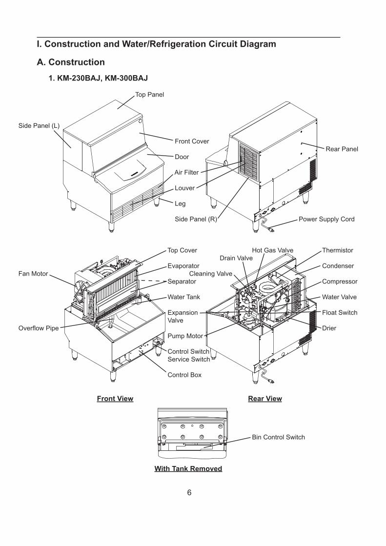
A. Construction1. KM-230BAJ, KM-300BAJ
Top Panel
Side Panel (L)
Front Cover Rear Panel Door
Air Filter
Louver
Leg
Side Panel (R) Power Supply Cord
Top Cover Hot Gas Valve Thermistor Drain Valve Evaporator CondenserFan Motor Cleaning Valve Separator Compressor
Water Tank Water Valve
Expansion Float Switch ValveOverflow Pipe Drier Pump Motor
Control Switch Service Switch
Control Box
Front View Rear View
Bin Control Switch
With Tank Removed
7
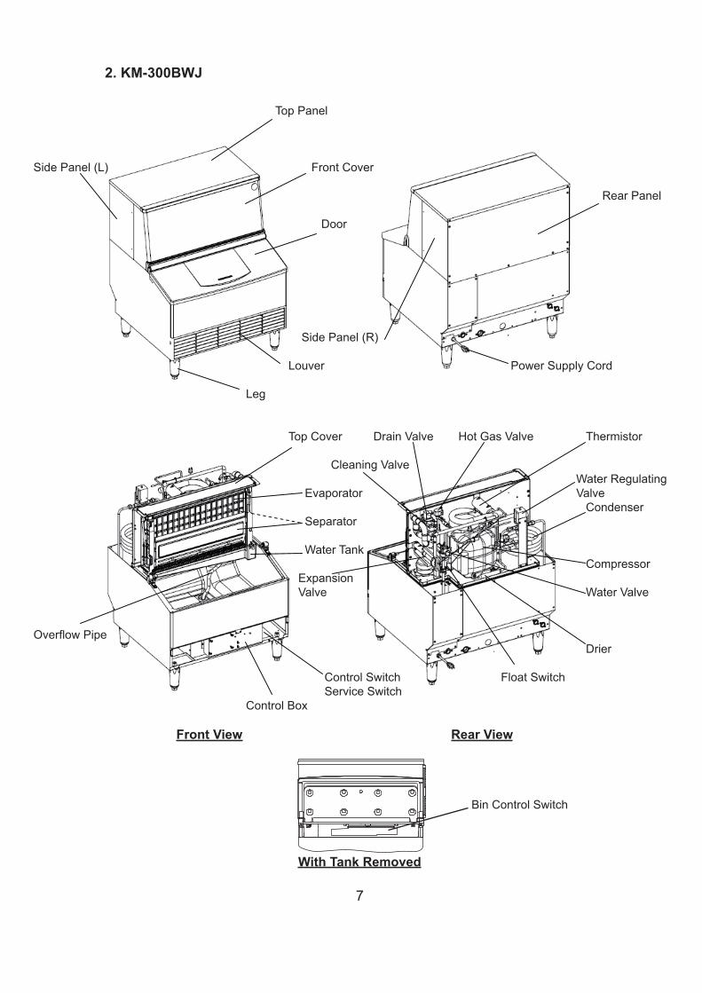
2. KM-300BWJ
Top Panel
Side Panel (L) Front Cover
Rear Panel
Door
Side Panel (R)
Louver Power Supply Cord
Leg
Top Cover Drain Valve Hot Gas Valve Thermistor
Cleaning Valve Water Regulating Evaporator Valve Condenser Separator
Water Tank Compressor Expansion Valve Water Valve
Overflow Pipe Drier
Control Switch Float Switch Service Switch Control Box
Front View Rear View
Bin Control Switch
With Tank Removed
8
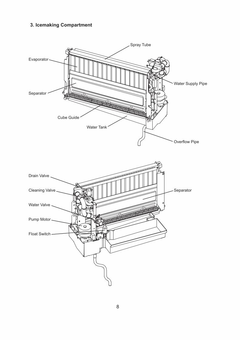
3. Icemaking Compartment
Spray Tube
Evaporator
Water Supply Pipe
Separator
Cube Guide
Water Tank
Overflow Pipe
Drain Valve
Cleaning Valve Separator
Water Valve
Pump Motor
Float Switch
9
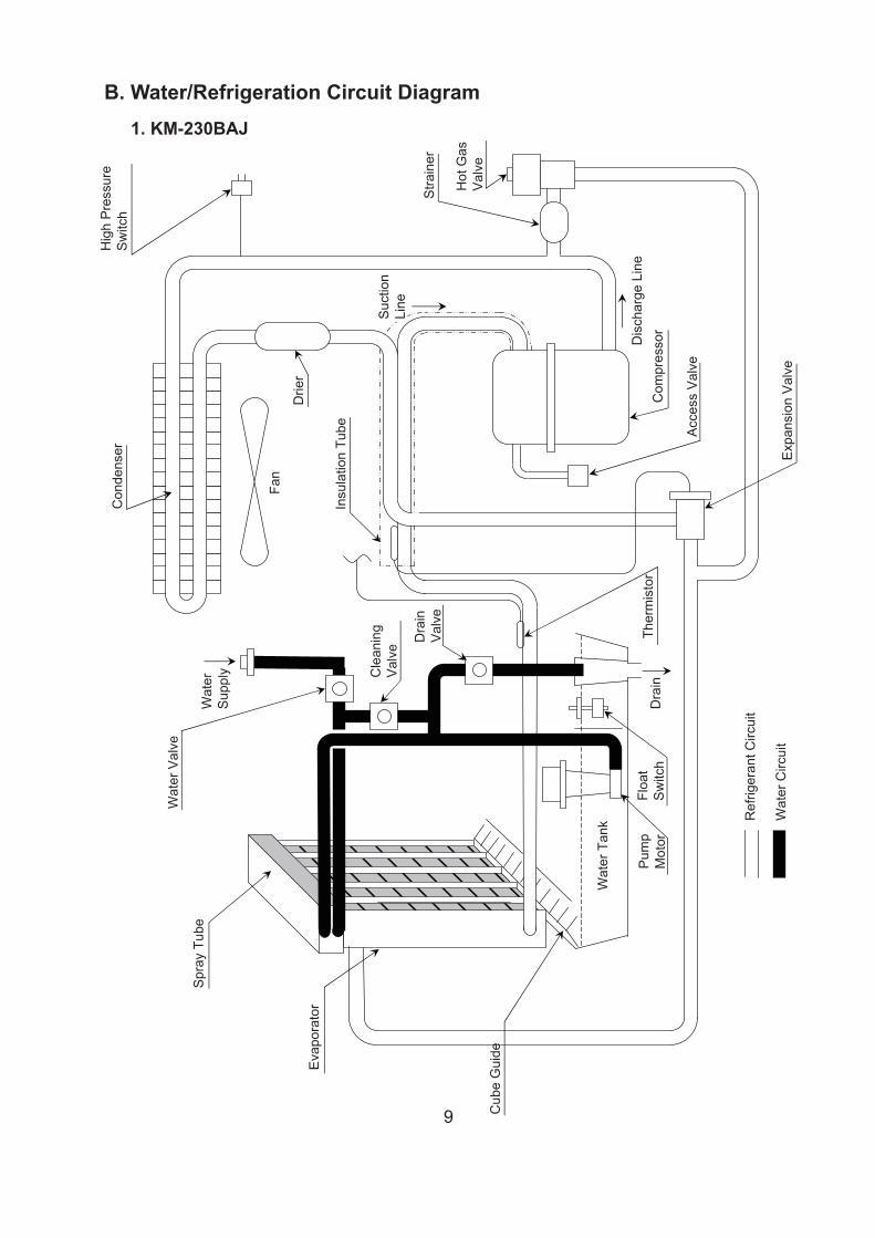
Eva
pora
tor
Floa
tS
witc
h
Cub
e G
uide
Drie
r
Ther
mis
tor
Suc
tion
Line
Wat
erS
uppl
y
Wat
er V
alve
Spr
ay T
ube
Fan
Con
dens
er Exp
ansi
on V
alve
Com
pres
sor
Acc
ess
Val
ve
Stra
iner
Hot
Gas
Val
ve
Hig
h P
ress
ure
Sw
itch
Ref
riger
ant C
ircui
t
Wat
er C
ircui
t
Dis
char
ge L
ine
Insu
latio
n Tu
be
Pum
pM
otor
Wat
er T
ank
Dra
in
Dra
inV
alve
Cle
anin
gV
alve
B. Water/Refrigeration Circuit Diagram1. KM-230BAJ
10
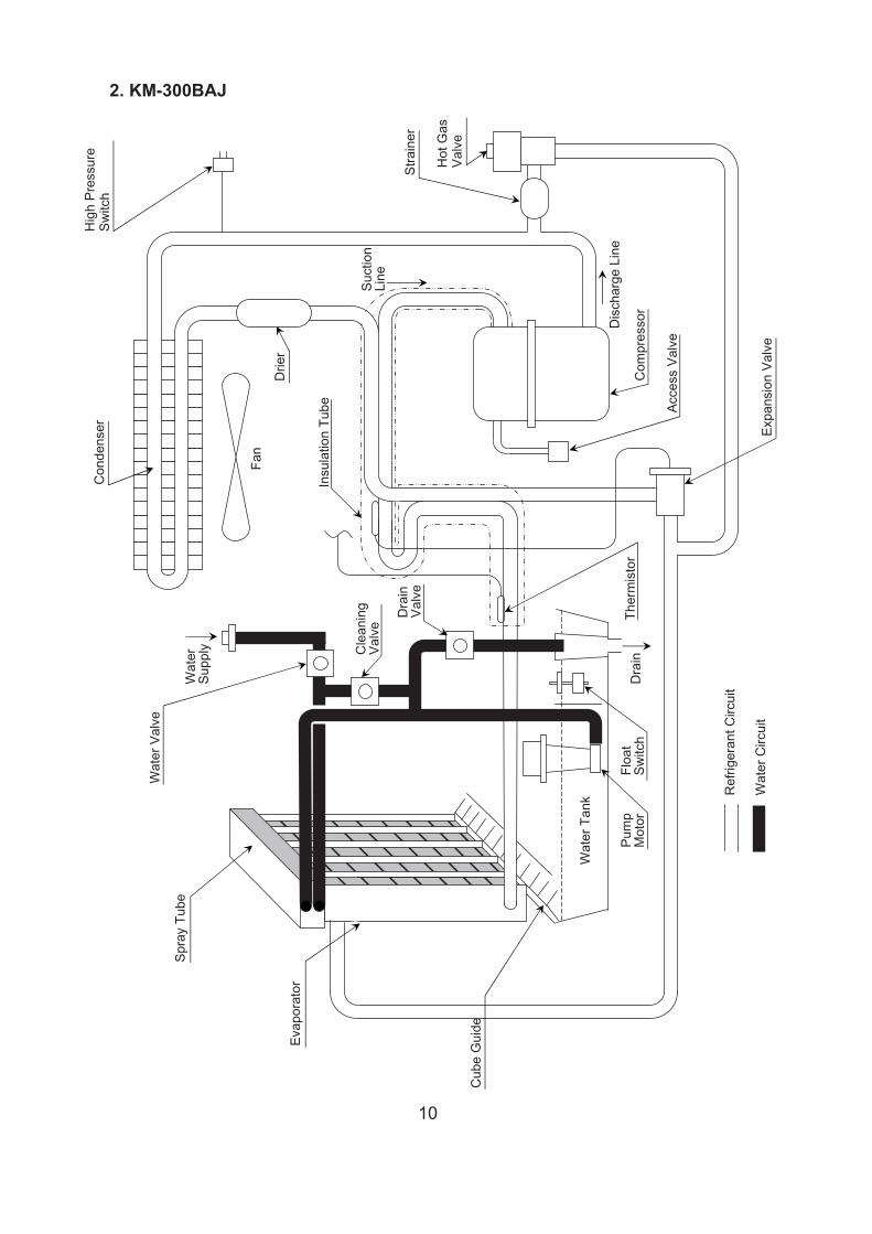
2. KM-300BAJ
Expa
nsio
n Va
lve
Com
pres
sor
Acce
ss V
alve
Dis
char
ge L
ine
Evap
orat
or
Floa
tSw
itch
Cub
e G
uide
Drie
r
Ther
mis
tor
Suct
ion
Line
Wat
erSu
pply
Wat
er V
alve
Spra
y Tu
be
Fan
Con
dens
erH
igh
Pres
sure
Switc
h
Ref
riger
ant C
ircui
t
Wat
er C
ircui
t
Insu
latio
n Tu
be
Pum
pM
otor
Wat
er T
ank
Dra
in
Dra
inVa
lve
Cle
anin
gVa
lve
Stra
iner
Hot
Gas
Valv
e
11
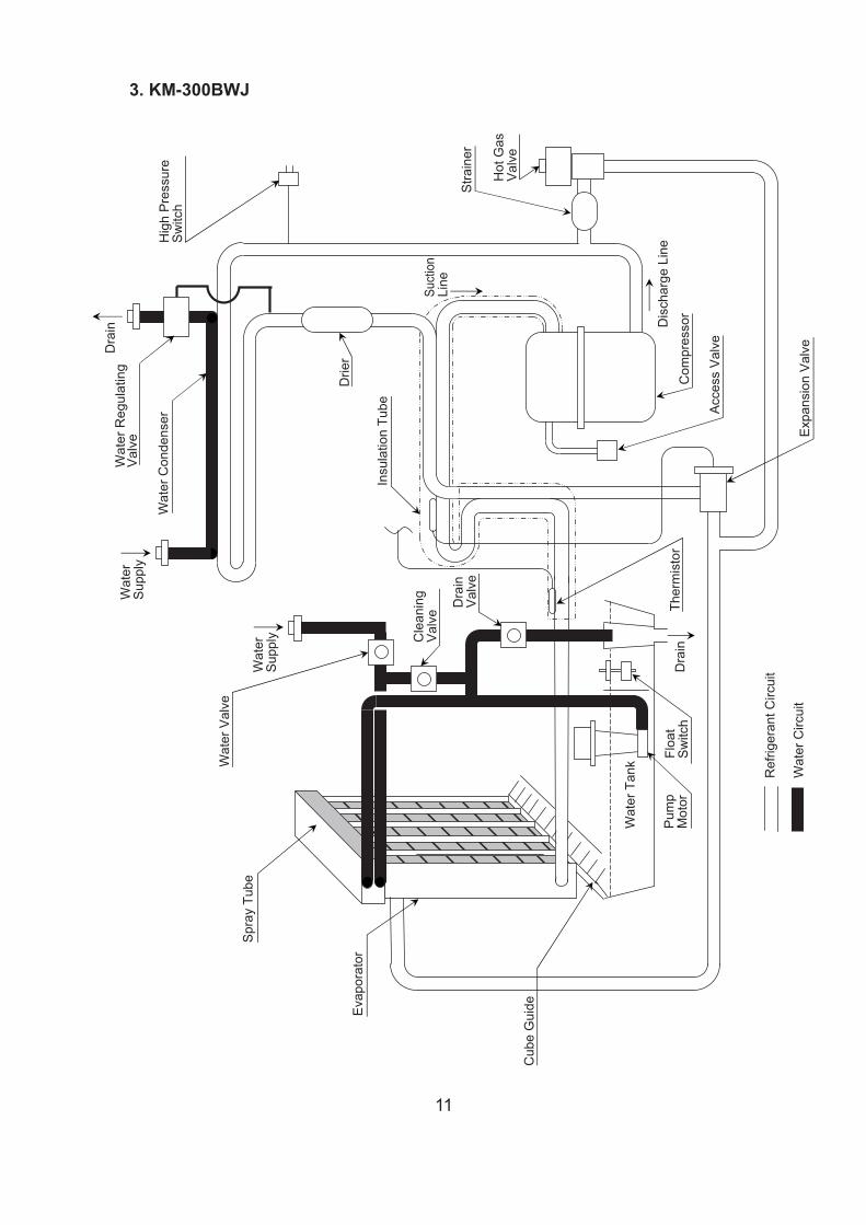
3. KM-300BWJ
Dra
in
Wat
er C
onde
nser
Hig
h P
ress
ure
Sw
itch
Wat
erS
uppl
yW
ater
Reg
ulat
ing
Val
ve
Wat
erS
uppl
y
Wat
er V
alve
Spr
ay T
ube
Stra
iner
Hot
Gas
Val
ve
Floa
tS
witc
hTh
erm
isto
r
Exp
ansi
on V
alve
Com
pres
sor
Acc
ess
Val
ve
Ref
riger
ant C
ircui
t
Wat
er C
ircui
t
Dis
char
ge L
ine
Pum
pM
otor
Wat
er T
ank
Dra
in
Eva
pora
tor
Cub
e G
uide
Drie
r
Suct
ion
Line
Insu
latio
n Tu
be
Cle
anin
gV
alve
Dra
inV
alve
12
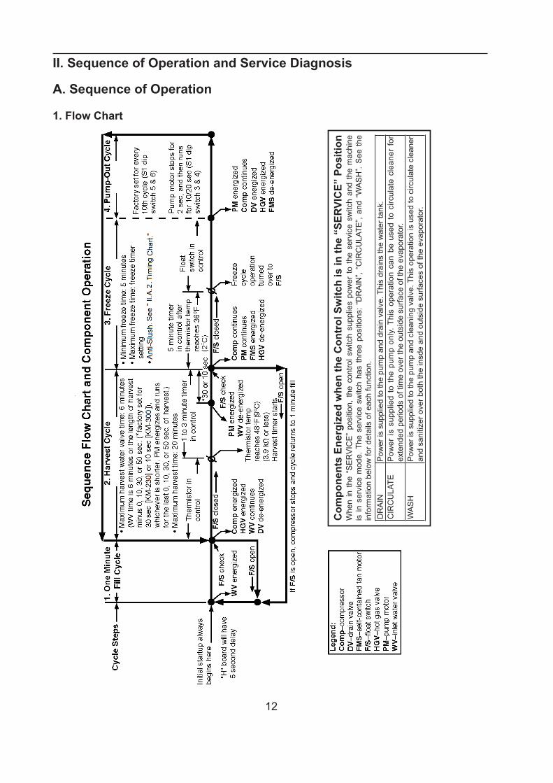
II. Sequence of Operation and Service Diagnosis
A. Sequence of Operation
1. Flow Chart
Com
pone
nts
Ener
gize
d w
hen
the
Con
trol
Sw
itch
is in
the
“SER
VIC
E” P
ositi
onW
hen
in t
he “
SE
RV
ICE
” po
sitio
n, t
he c
ontro
l sw
itch
supp
lies
pow
er t
o th
e se
rvic
e sw
itch
and
the
mac
hine
is
in s
ervi
ce m
ode.
The
ser
vice
sw
itch
has
thre
e po
sitio
ns:
“DR
AIN
”, “C
IRC
ULA
TE”,
and
“WA
SH
”. S
ee t
he
info
rmat
ion
belo
w fo
r det
ails
of e
ach
func
tion.
DR
AIN
Pow
er is
sup
plie
d to
the
pum
p an
d dr
ain
valv
e. T
his
drai
ns th
e w
ater
tank
.C
IRC
ULA
TEP
ower
is s
uppl
ied
to t
he p
ump
only
. Thi
s op
erat
ion
can
be u
sed
to c
ircul
ate
clea
ner
for
exte
nded
per
iods
of t
ime
over
the
outs
ide
surfa
ce o
f the
eva
pora
tor.
WA
SH
Pow
er is
sup
plie
d to
the
pum
p an
d cl
eani
ng v
alve
. Thi
s op
erat
ion
is u
sed
to c
ircul
ate
clea
ner
and
sani
tizer
ove
r bot
h th
e in
sde
and
outs
ide
surfa
ces
of th
e ev
apor
ator
.
13
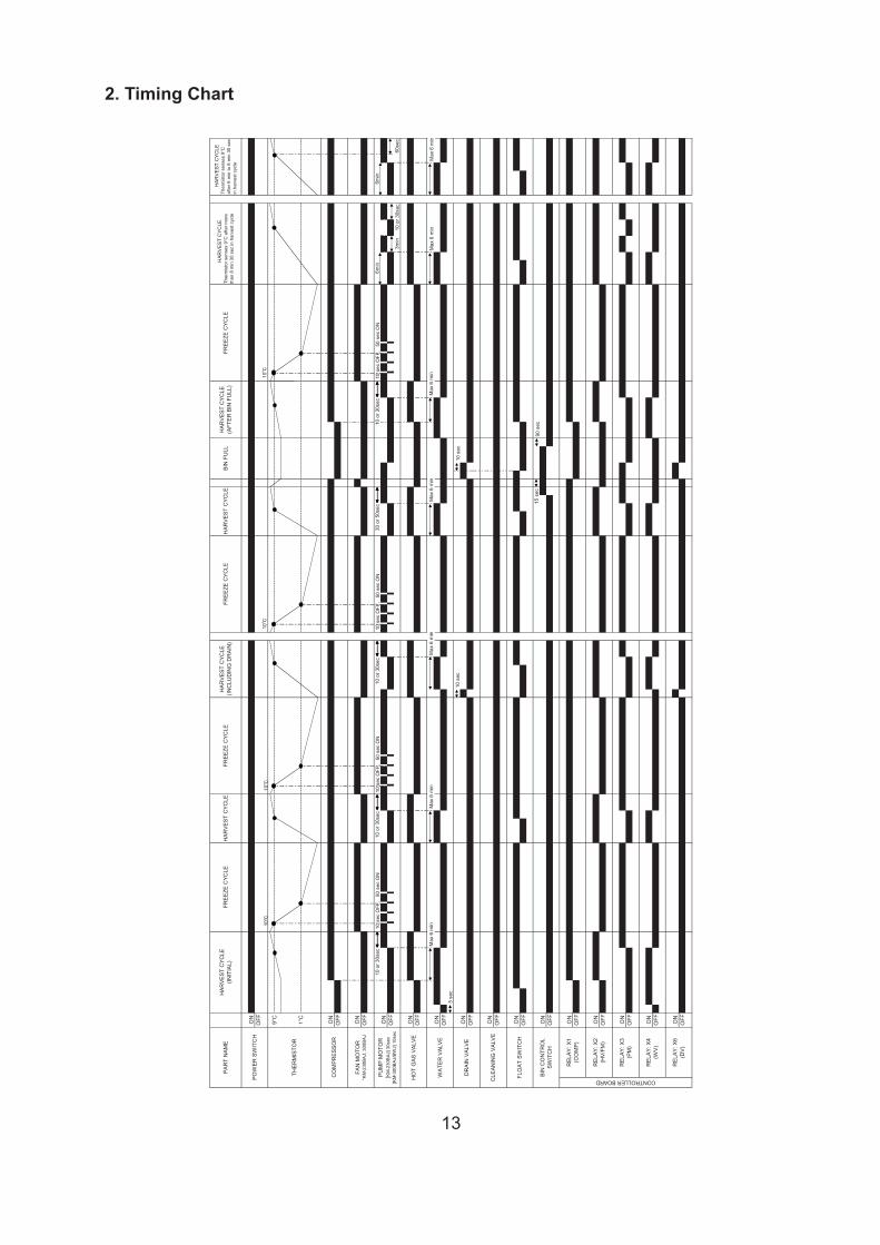
10 o
r 30s
ec10
or 3
0sec
10 o
r 30s
ec30
or 5
0sec
10 o
r 30s
ec
10 o
r 30s
ec
BIN
FU
LLPA
RT
NAM
EH
ARVE
ST C
YCLE
(INIT
IAL)
FREE
ZE C
YCLE
HAR
VEST
CYC
LEFR
EEZE
CYC
LE
POW
ER S
WIT
CH
ON
OFF
THER
MIS
TOR
9°C
HAR
VEST
CYC
LE(IN
CLU
DIN
G D
RAI
N)
OFF
HAR
VEST
CYC
LE(A
FTER
BIN
FU
LL)
FREE
ZE C
YCLE
H
AR
VE
ST
CYC
LETh
erm
isto
r sen
ses
9°C
afte
r mor
eth
an 8
min
30
sec
in h
arve
st c
ycle
H
AR
VE
ST
CYC
LETh
erm
isto
r sen
ses
9°C
afte
r 6 m
in to
8 m
in 3
0 se
cin
har
vest
cyc
le
FREE
ZE C
YCLE
HAR
VEST
CYC
LE
6min
OFF
3min
1°C
CO
MPR
ESSO
RO
NO
FF
FAN
MO
TOR
*KM
-230
BA
J, 3
00B
AJ
ON
60se
c
HO
T G
AS V
ALVE
ON
OFF
WAT
ER V
ALVE
ON
OFF
PUM
P M
OTO
R[K
M-2
30B
AJ]
30s
ec[K
M-3
00B
AJ/
BW
J] 1
0sec
ON
6min
DR
AIN
VAL
VEO
NO
FF
CLE
ANIN
G V
ALVE
ON
OFF
FLO
AT S
WIT
CH
ON
OFF
BIN
CO
NTR
OL
SWIT
CH
ON
OFF
CONTROLLER BOARD
REL
AY: X
1(C
OM
P)O
NO
FF
REL
AY: X
2(H
V/FM
)O
NO
FF
REL
AY: X
3(P
M)
ON
OFF
REL
AY: X
4(W
V)O
NO
FF
REL
AY: X
6(D
V)O
NO
FF
Max
6 m
in
5 se
c
Max
6 m
inM
ax 6
min
10 s
ec
Max
6 m
in
15 s
ec
10 s
ec
90 s
ec
Max
6 m
in
10 s
ec O
FF,
50
sec
ON
10 s
ec O
FF,
50
sec
ON
10 s
ec O
FF,
50
sec
ON
10
10
10
10 s
ec O
FF,
50
sec
ON
10
Max
6 m
inM
ax 6
min
2. Timing Chart
14
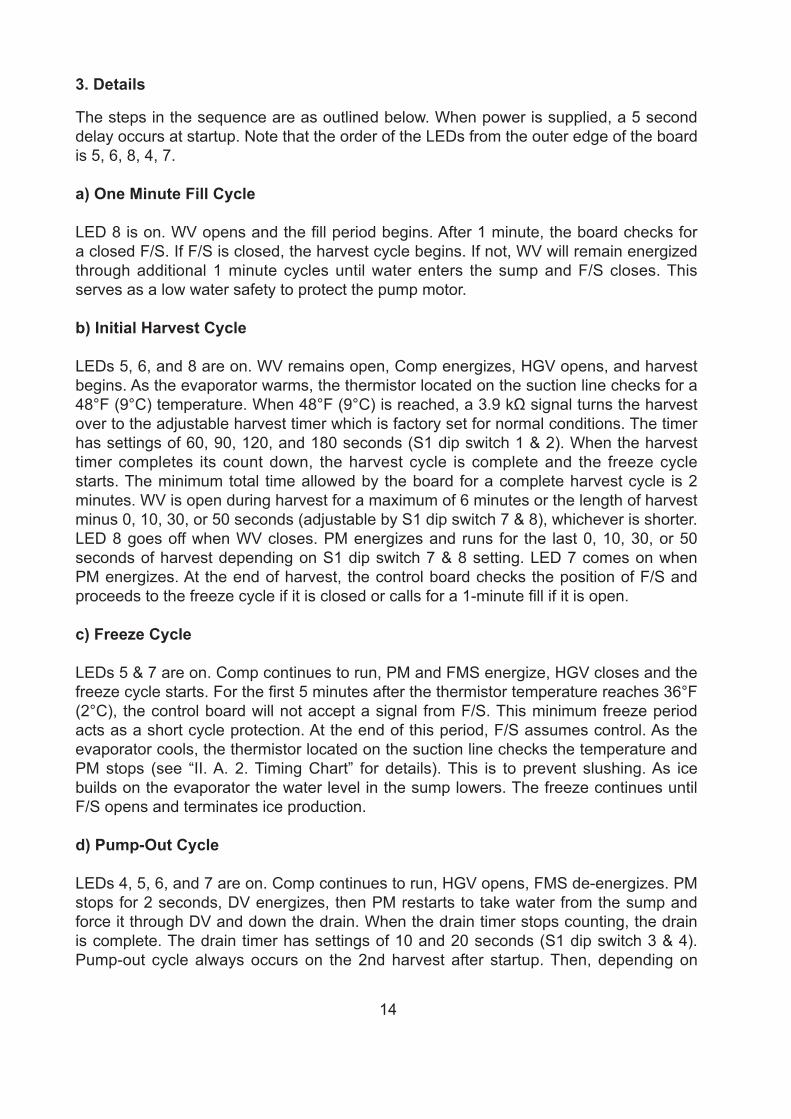
3. Details
The steps in the sequence are as outlined below. When power is supplied, a 5 second delay occurs at startup. Note that the order of the LEDs from the outer edge of the board is 5, 6, 8, 4, 7.
a) One Minute Fill Cycle
LED 8 is on. WV opens and the fill period begins. After 1 minute, the board checks for a closed F/S. If F/S is closed, the harvest cycle begins. If not, WV will remain energized through additional 1 minute cycles until water enters the sump and F/S closes. This serves as a low water safety to protect the pump motor.
b) Initial Harvest Cycle
LEDs 5, 6, and 8 are on. WV remains open, Comp energizes, HGV opens, and harvest begins. As the evaporator warms, the thermistor located on the suction line checks for a 48°F (9°C) temperature. When 48°F (9°C) is reached, a 3.9 kΩ signal turns the harvest over to the adjustable harvest timer which is factory set for normal conditions. The timer has settings of 60, 90, 120, and 180 seconds (S1 dip switch 1 & 2). When the harvest timer completes its count down, the harvest cycle is complete and the freeze cycle starts. The minimum total time allowed by the board for a complete harvest cycle is 2 minutes. WV is open during harvest for a maximum of 6 minutes or the length of harvest minus 0, 10, 30, or 50 seconds (adjustable by S1 dip switch 7 & 8), whichever is shorter. LED 8 goes off when WV closes. PM energizes and runs for the last 0, 10, 30, or 50 seconds of harvest depending on S1 dip switch 7 & 8 setting. LED 7 comes on when PM energizes. At the end of harvest, the control board checks the position of F/S and proceeds to the freeze cycle if it is closed or calls for a 1-minute fill if it is open.
c) Freeze Cycle
LEDs 5 & 7 are on. Comp continues to run, PM and FMS energize, HGV closes and the freeze cycle starts. For the first 5 minutes after the thermistor temperature reaches 36°F (2°C), the control board will not accept a signal from F/S. This minimum freeze period acts as a short cycle protection. At the end of this period, F/S assumes control. As the evaporator cools, the thermistor located on the suction line checks the temperature and PM stops (see “II. A. 2. Timing Chart” for details). This is to prevent slushing. As ice builds on the evaporator the water level in the sump lowers. The freeze continues until F/S opens and terminates ice production.
d) Pump-Out Cycle
LEDs 4, 5, 6, and 7 are on. Comp continues to run, HGV opens, FMS de-energizes. PM stops for 2 seconds, DV energizes, then PM restarts to take water from the sump and force it through DV and down the drain. When the drain timer stops counting, the drain is complete. The drain timer has settings of 10 and 20 seconds (S1 dip switch 3 & 4). Pump-out cycle always occurs on the 2nd harvest after startup. Then, depending on
15
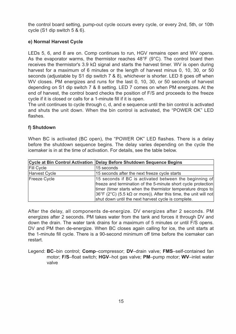
the control board setting, pump-out cycle occurs every cycle, or every 2nd, 5th, or 10th cycle (S1 dip switch 5 & 6).
e) Normal Harvest Cycle
LEDs 5, 6, and 8 are on. Comp continues to run, HGV remains open and WV opens. As the evaporator warms, the thermistor reaches 48°F (9°C). The control board then receives the thermistor's 3.9 kΩ signal and starts the harvest timer. WV is open during harvest for a maximum of 6 minutes or the length of harvest minus 0, 10, 30, or 50 seconds (adjustable by S1 dip switch 7 & 8), whichever is shorter. LED 8 goes off when WV closes. PM energizes and runs for the last 0, 10, 30, or 50 seconds of harvest depending on S1 dip switch 7 & 8 setting. LED 7 comes on when PM energizes. At the end of harvest, the control board checks the position of F/S and proceeds to the freeze cycle if it is closed or calls for a 1-minute fill if it is open.The unit continues to cycle through c, d, and e sequence until the bin control is activated and shuts the unit down. When the bin control is activated, the “POWER OK” LED flashes.
f) Shutdown
When BC is activated (BC open), the “POWER OK” LED flashes. There is a delay before the shutdown sequence begins. The delay varies depending on the cycle the icemaker is in at the time of activation. For details, see the table below.
Cycle at Bin Control Activation Delay Before Shutdown Sequence BeginsFill Cycle 15 secondsHarvest Cycle 15 seconds after the next freeze cycle startsFreeze Cycle 15 seconds if BC is activated between the beginning of
freeze and termination of the 5-minute short cycle protection timer (timer starts when the thermistor temperature drops to 36°F (2°C) (5.5 kΩ or more)). After this time, the unit will not shut down until the next harvest cycle is complete.
After the delay, all components de-energize. DV energizes after 2 seconds. PM energizes after 2 seconds. PM takes water from the tank and forces it through DV and down the drain. The water tank drains for a maximum of 5 minutes or until F/S opens. DV and PM then de-energize. When BC closes again calling for ice, the unit starts at the 1-minute fill cycle. There is a 90-second minimum off time before the icemaker can restart.
Legend: BC–bin control; Comp–compressor; DV–drain valve; FMS–self-contained fan motor; F/S–float switch; HGV–hot gas valve; PM–pump motor; WV–inlet water valve
16
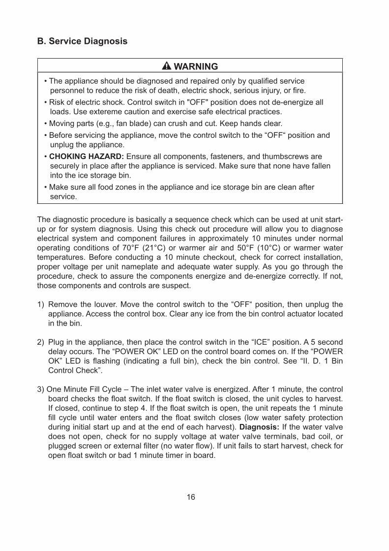
B. Service Diagnosis
WARNING• The appliance should be diagnosed and repaired only by qualified service
personnel to reduce the risk of death, electric shock, serious injury, or fire. • Risk of electric shock. Control switch in "OFF" position does not de-energize all
loads. Use extereme caution and exercise safe electrical practices.• Moving parts (e.g., fan blade) can crush and cut. Keep hands clear.• Before servicing the appliance, move the control switch to the “OFF“ position and
unplug the appliance.• CHOKING HAZARD: Ensure all components, fasteners, and thumbscrews are
securely in place after the appliance is serviced. Make sure that none have fallen into the ice storage bin.
• Make sure all food zones in the appliance and ice storage bin are clean after service.
The diagnostic procedure is basically a sequence check which can be used at unit start-up or for system diagnosis. Using this check out procedure will allow you to diagnose electrical system and component failures in approximately 10 minutes under normal operating conditions of 70°F (21°C) or warmer air and 50°F (10°C) or warmer water temperatures. Before conducting a 10 minute checkout, check for correct installation, proper voltage per unit nameplate and adequate water supply. As you go through the procedure, check to assure the components energize and de-energize correctly. If not, those components and controls are suspect.
1) Remove the louver. Move the control switch to the “OFF“ position, then unplug the appliance. Access the control box. Clear any ice from the bin control actuator located in the bin.
2) Plug in the appliance, then place the control switch in the “ICE” position. A 5 second delay occurs. The “POWER OK” LED on the control board comes on. If the “POWER OK” LED is flashing (indicating a full bin), check the bin control. See “II. D. 1 Bin Control Check”.
3) One Minute Fill Cycle – The inlet water valve is energized. After 1 minute, the control board checks the float switch. If the float switch is closed, the unit cycles to harvest. If closed, continue to step 4. If the float switch is open, the unit repeats the 1 minute fill cycle until water enters and the float switch closes (low water safety protection during initial start up and at the end of each harvest). Diagnosis: If the water valve does not open, check for no supply voltage at water valve terminals, bad coil, or plugged screen or external filter (no water flow). If unit fails to start harvest, check for open float switch or bad 1 minute timer in board.
17
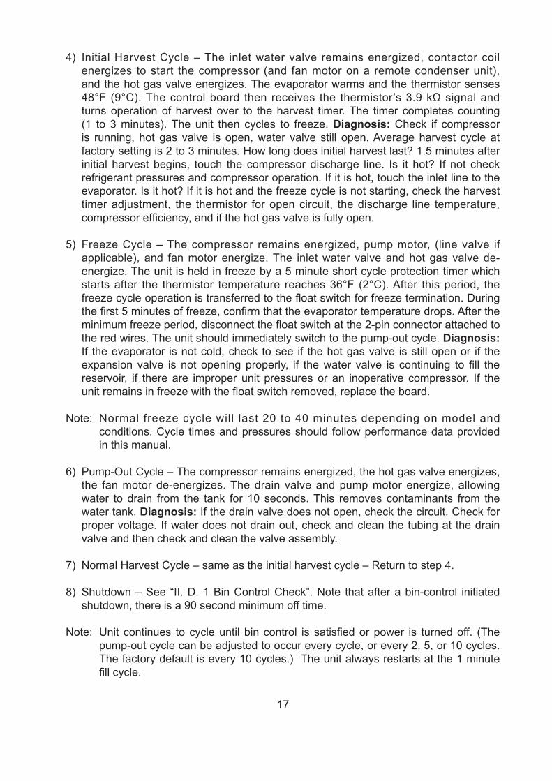
4) Initial Harvest Cycle – The inlet water valve remains energized, contactor coil energizes to start the compressor (and fan motor on a remote condenser unit), and the hot gas valve energizes. The evaporator warms and the thermistor senses 48°F (9°C). The control board then receives the thermistor’s 3.9 kΩ signal and turns operation of harvest over to the harvest timer. The timer completes counting (1 to 3 minutes). The unit then cycles to freeze. Diagnosis: Check if compressor is running, hot gas valve is open, water valve still open. Average harvest cycle at factory setting is 2 to 3 minutes. How long does initial harvest last? 1.5 minutes after initial harvest begins, touch the compressor discharge line. Is it hot? If not check refrigerant pressures and compressor operation. If it is hot, touch the inlet line to the evaporator. Is it hot? If it is hot and the freeze cycle is not starting, check the harvest timer adjustment, the thermistor for open circuit, the discharge line temperature, compressor efficiency, and if the hot gas valve is fully open.
5) Freeze Cycle – The compressor remains energized, pump motor, (line valve if applicable), and fan motor energize. The inlet water valve and hot gas valve de-energize. The unit is held in freeze by a 5 minute short cycle protection timer which starts after the thermistor temperature reaches 36°F (2°C). After this period, the freeze cycle operation is transferred to the float switch for freeze termination. During the first 5 minutes of freeze, confirm that the evaporator temperature drops. After the minimum freeze period, disconnect the float switch at the 2-pin connector attached to the red wires. The unit should immediately switch to the pump-out cycle. Diagnosis: If the evaporator is not cold, check to see if the hot gas valve is still open or if the expansion valve is not opening properly, if the water valve is continuing to fill the reservoir, if there are improper unit pressures or an inoperative compressor. If the unit remains in freeze with the float switch removed, replace the board.
Note: Normal freeze cycle will last 20 to 40 minutes depending on model and conditions. Cycle times and pressures should follow performance data provided in this manual.
6) Pump-Out Cycle – The compressor remains energized, the hot gas valve energizes, the fan motor de-energizes. The drain valve and pump motor energize, allowing water to drain from the tank for 10 seconds. This removes contaminants from the water tank. Diagnosis: If the drain valve does not open, check the circuit. Check for proper voltage. If water does not drain out, check and clean the tubing at the drain valve and then check and clean the valve assembly.
7) Normal Harvest Cycle – same as the initial harvest cycle – Return to step 4.
8) Shutdown – See “II. D. 1 Bin Control Check”. Note that after a bin-control initiated shutdown, there is a 90 second minimum off time.
Note: Unit continues to cycle until bin control is satisfied or power is turned off. (The pump-out cycle can be adjusted to occur every cycle, or every 2, 5, or 10 cycles. The factory default is every 10 cycles.) The unit always restarts at the 1 minute fill cycle.
18
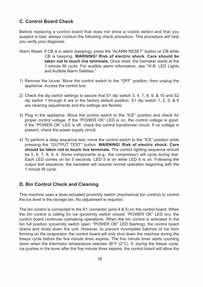
C. Control Board Check
Before replacing a control board that does not show a visible defect and that you suspect is bad, always conduct the following check procedure. This procedure will help you verify your diagnosis.
Alarm Reset: If CB is in alarm (beeping), press the “ALARM RESET” button on CB while CB is beeping. WARNING! Risk of electric shock. Care should be taken not to touch live terminals. Once reset, the icemaker starts at the 1-minute fill cycle. For audible alarm information, see “III.B. LED Lights and Audible Alarm Safeties.”
1) Remove the louver. Move the control switch to the “OFF” position, then unplug the appliance. Access the control box.
2) Check the dip switch settings to assure that S1 dip switch 3, 4, 7, 8, 9, & 10 and S2 dip switch 1 through 6 are in the factory default position. S1 dip switch 1, 2, 5, & 6 are cleaning adjustments and the settings are flexible.
3) Plug in the appliance. Move the control switch to the “ICE” position and check for proper control voltage. If the “POWER OK” LED is on, the control voltage is good. If the “POWER OK” LED is off, check the control transformer circuit. If no voltage is present, check the power supply circuit.
4) To perform a relay sequence test, move the control switch to the “ICE“ position while pressing the “OUTPUT TEST” button. WARNING! Risk of electric shock. Care should be taken not to touch live terminals. The correct lighting sequence should be 5, 6, 7, 8, 9, 4. Some components (e.g., the compressor) will cycle during test. Each LED comes on for 5 seconds. LED 5 is on while LED 6 is on. Following the output test sequence, the icemaker will resume normal operation beginning with the 1 minute fill cycle.
D. Bin Control Check and Cleaning
This machine uses a lever-actuated proximity switch (mechanical bin control) to control the ice level in the storage bin. No adjustment is required.
The bin control is connected to the K1 connector (pins 4 & 5) on the control board. When the bin control is calling for ice (proximity switch closed; “POWER OK” LED on), the control board continues icemaking operations. When the bin control is activated in the bin full position (proximity switch open; “POWER OK” LED flashing), the control board drains and shuts down the unit. However, to prevent incomplete batches of ice from forming on the evaporator, the control board will only shut down the machine during the freeze cycle before the five minute timer expires. The five minute timer starts counting down when the thermistor temperature reaches 36°F (2°C). If, during the freeze cycle, ice pushes in the lever after the five minute timer expires, the control board will allow the
19
machine to complete the freeze cycle and the following harvest cycle before shutting down the machine.
When the bin control is activated, the “POWER OK” LED flashes. There is a delay before the shutdown sequence begins. The delay varies depending on the cycle the icemaker is in at the time of activation. For details, see the table below.
Cycle at Bin Control Activation Delay Before Shutdown Sequence BeginsFill Cycle 15 secondsHarvest Cycle 15 seconds after the next freeze cycle startsFreeze Cycle 15 seconds if the bin control is activated between the
beginning of freeze and termination of the 5-minute short cycle protection timer (timer starts when the thermistor temperature drops to 36°F (2°C) (5.5 kΩ or more)). After this time, the unit will not shut down until the next harvest cycle is complete.
1. Bin Control Check
1) Remove the louver. Move the control switch to the “OFF” position, then unplug the appliance. Access the control box.
2) Clear any ice away from the bin control.
3) Disconnect the bin control at the 2-pin connector attached to the black wires coming from the K1 connector (pins 4 & 5) on the control board.
4) Check for continuity across the bin control leads. When calling for ice, the bin control proximity switch should be closed. If open, replace the bin control. Activate the bin control actuator (press the actuator in), check for continuity across the bin control leads. The bin control proximity switch should be open. If closed, replace the bin control.
5) Reconnect the 2-pin connector. Plug in the appliance, then move the control switch to the “ICE“ position. Allow the machine to cycle into the freeze cycle. In the first 5 minutes of the freeze cycle, activate the bin control actuator (press the actuator in). The “POWER OK” LED should flash and the machine should turn off. If not, replace the control board.
2. Bin Control Cleaning
Scale may build up on MBC. Scale can cause the actuator paddle and magnet to stick. In this case, MBC should be cleaned.
20
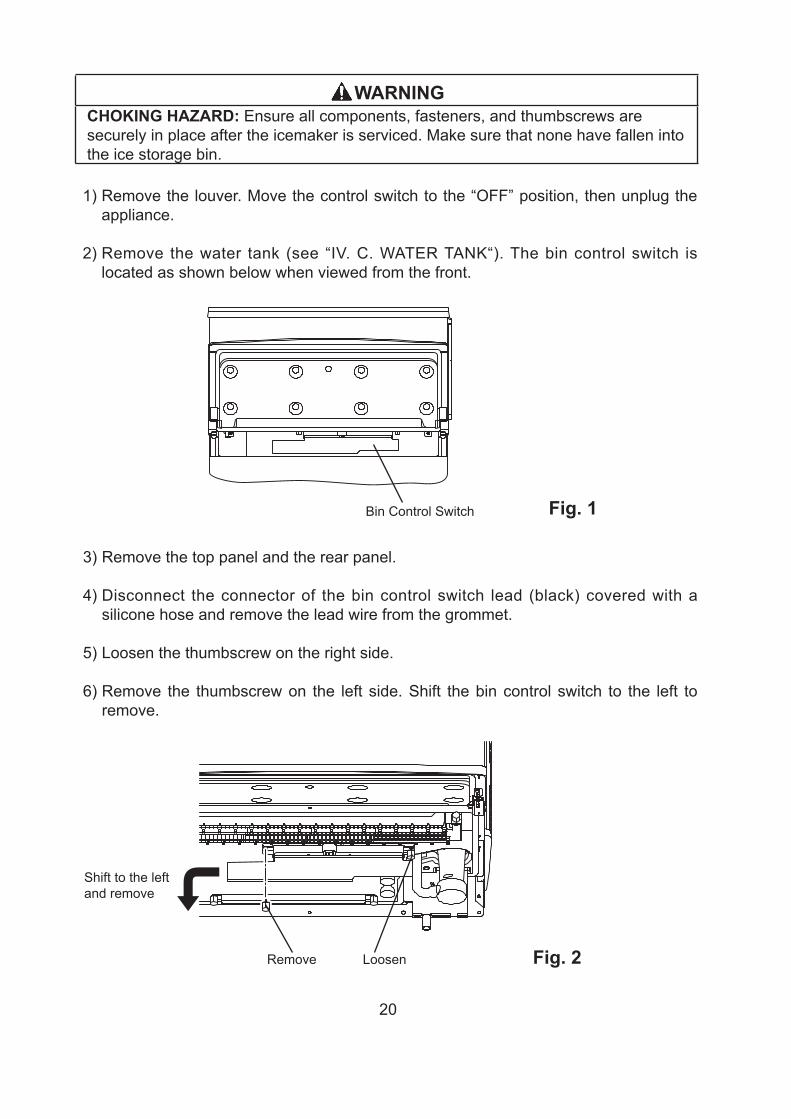
Fig. 1Bin Control Switch
Fig. 2Remove Loosen
Shift to the left and remove
WARNINGCHOKING HAZARD: Ensure all components, fasteners, and thumbscrews are securely in place after the icemaker is serviced. Make sure that none have fallen into the ice storage bin.
1) Remove the louver. Move the control switch to the “OFF” position, then unplug the appliance.
2) Remove the water tank (see “IV. C. WATER TANK“). The bin control switch is located as shown below when viewed from the front.
3) Remove the top panel and the rear panel.
4) Disconnect the connector of the bin control switch lead (black) covered with a silicone hose and remove the lead wire from the grommet.
5) Loosen the thumbscrew on the right side.
6) Remove the thumbscrew on the left side. Shift the bin control switch to the left to remove.
21
7) Wipe down MBC with a mixture of 1 part of Hoshizaki “Scale Away” and 25 parts of warm water. Rinse the parts thoroughly with clean water.
8) Refit the removed parts in the reverse order of the removal procedure.
9) Plug in the appliance.
Legend: MBC–mechanical bin control
E. Float Switch Check and Cleaning
FS is used to determine that there is sufficient water in the water tank after the 1-min. fill cycle and after each harvest cycle. FS is also used to determine that the appropriate volume of water has been converted into ice before switching out of the freeze cycle. No adjustment is required.
1. Float Switch Check
To check FS, follow the steps below.
1) Remove the louver.
2) Drain out the water tank by leaving the control switch in the “SERVICE“ position and the service switch in the “DRAIN“ position until the tank is empty.
3) Move the control switch to the “OFF“ position, then unplug the appliance.
4) Remove the top panel, rear panel and right side panel.
5) Disconnect the connector of the FS lead.
6) Check for continuity across FS leads. With the water tank empty, FS should be open. If open, continue to step 7. If closed, follow the steps in “II. E. 2. Float Switch Cleaning.“ After cleaning FS, check it again. Replace if necessary.
7) Reconnect FS connector.
8) Move the control switch to the “ICE” position. Replace the top panel, rear panel and right side panel in their correct positions, then plug in the appliance. After 1 min., the 1-min. fill cycle should end and the initial harvest cycle should begin. If the initial harvest cycle begins, FS is good and the check is complete. If the initial harvest cycle does not begin, continue to step 9.
9)Move the control switch to the “OFF” position, then unplug the appliance.
10) Remove the top panel, rear panel and right side panel.
22
11) Disconnect the connector of the FS lead.
12) Check for continuity across FS leads. With the water tank full, FS should be closed. If FS is closed and the icemaker will not switch from the 1-min. fill cycle to the initial harvest cycle, replace CB.
If FS is open, confirm that the water tank is full. If the water tank is not full, check the water supply, water filters, and inlet water valve. If the water tank is full, follow the steps in “II.E.2. Float Switch Cleaning.” After cleaning FS, check it again. Replace if necessary.
Legend: CB–control board; FS-float switch
2. Float Switch Cleaning
Depending on local water conditions, scale may build up on FS. Scale on the switch can cause the float to stick. In this case, FS should be cleaned.
1) Remove the louver.
2) Drain out the water tank by leaving the control switch in the “SERVICE“ position and the service switch in the “DRAIN“ position until the tank is empty.
3) Move the control switch to the “OFF“ position, then unplug the appliance.
4) Remove the top panel, rear panel and right side panel.
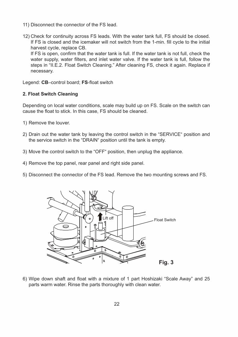
5) Disconnect the connector of the FS lead. Remove the two mounting screws and FS.
Fig. 3
Float SwitchLift off
6) Wipe down shaft and float with a mixture of 1 part Hoshizaki “Scale Away” and 25 parts warm water. Rinse the parts thoroughly with clean water.
23
7) Replace FS in its correct position and secure it with the two screws. Then connect FS connector.
8) Replace the right side panel, rear panel and top panel in their correct positions.
9) Plug in the appliance, then move the control switch to the “ICE” position.
Legend: CB–control board; FS-float switch
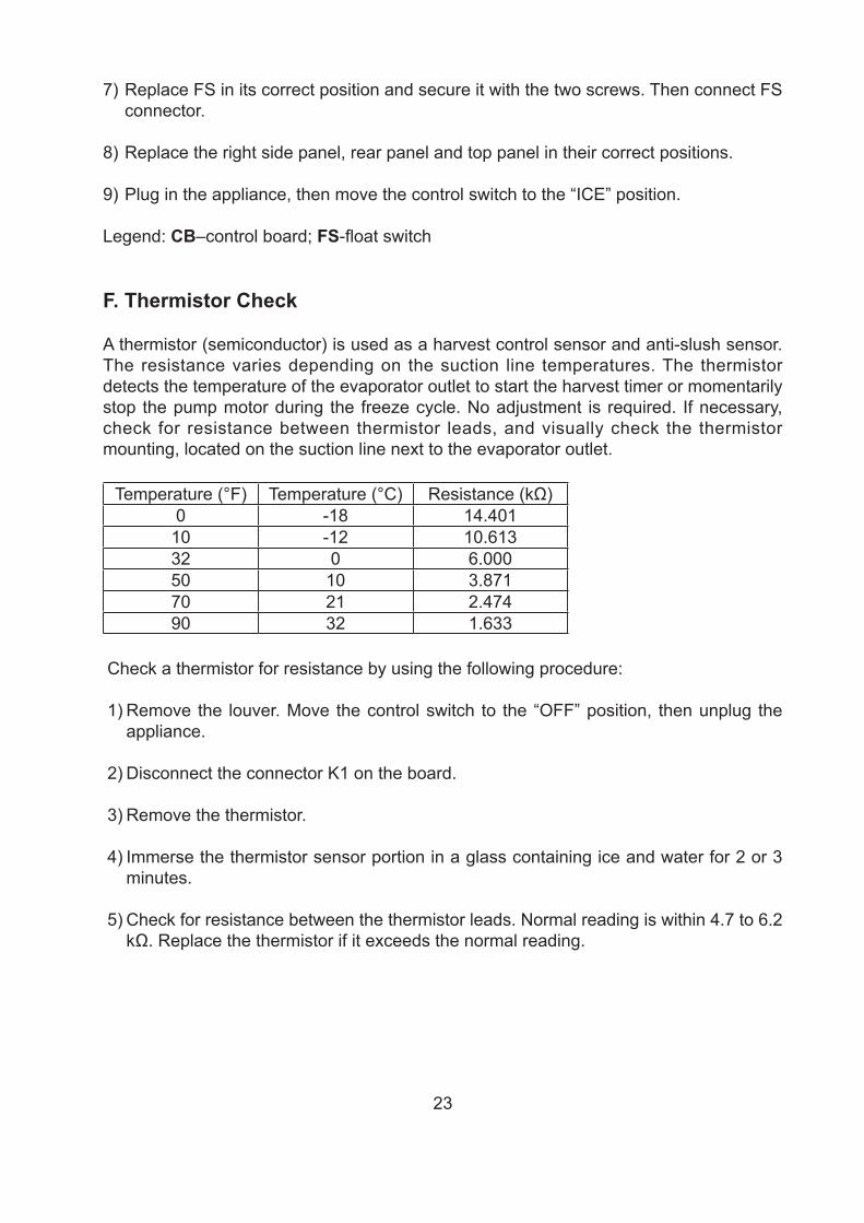
F. Thermistor Check
A thermistor (semiconductor) is used as a harvest control sensor and anti-slush sensor. The resistance varies depending on the suction line temperatures. The thermistor detects the temperature of the evaporator outlet to start the harvest timer or momentarily stop the pump motor during the freeze cycle. No adjustment is required. If necessary, check for resistance between thermistor leads, and visually check the thermistor mounting, located on the suction line next to the evaporator outlet.
Temperature (°F) Temperature (°C) Resistance (kΩ)0 -18 14.40110 -12 10.61332 0 6.00050 10 3.87170 21 2.47490 32 1.633
Check a thermistor for resistance by using the following procedure:
1) Remove the louver. Move the control switch to the “OFF” position, then unplug the appliance.
2) Disconnect the connector K1 on the board.
3) Remove the thermistor.
4) Immerse the thermistor sensor portion in a glass containing ice and water for 2 or 3 minutes.
5) Check for resistance between the thermistor leads. Normal reading is within 4.7 to 6.2 kΩ. Replace the thermistor if it exceeds the normal reading.
24
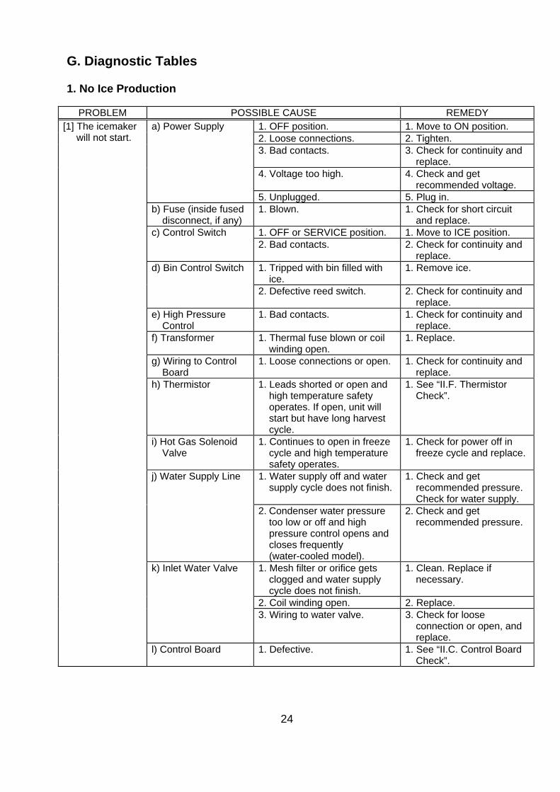
G. Diagnostic Tables 1. No Ice Production
PROBLEM POSSIBLE CAUSE REMEDY [1] The icemaker
will not start. a) Power Supply 1. OFF position. 1. Move to ON position.
2. Loose connections. 2. Tighten. 3. Bad contacts. 3. Check for continuity and
replace. 4. Voltage too high. 4. Check and get
recommended voltage. 5. Unplugged. 5. Plug in.
b) Fuse (inside fused disconnect, if any)
1. Blown. 1. Check for short circuit and replace.
c) Control Switch 1. OFF or SERVICE position. 1. Move to ICE position. 2. Bad contacts. 2. Check for continuity and
replace. d) Bin Control Switch 1. Tripped with bin filled with
ice. 1. Remove ice.
2. Defective reed switch. 2. Check for continuity and replace.
e) High Pressure Control
1. Bad contacts. 1. Check for continuity and replace.
f) Transformer 1. Thermal fuse blown or coil winding open.
1. Replace.
g) Wiring to Control Board
1. Loose connections or open. 1. Check for continuity and replace.
h) Thermistor 1. Leads shorted or open and high temperature safety operates. If open, unit will start but have long harvest cycle.
1. See “II.F. Thermistor Check”.
i) Hot Gas Solenoid Valve
1. Continues to open in freeze cycle and high temperature safety operates.
1. Check for power off in freeze cycle and replace.
j) Water Supply Line 1. Water supply off and water supply cycle does not finish.
1. Check and get recommended pressure. Check for water supply.
2. Condenser water pressure too low or off and high pressure control opens and closes frequently (water-cooled model).
2. Check and get recommended pressure.
k) Inlet Water Valve 1. Mesh filter or orifice gets clogged and water supply cycle does not finish.
1. Clean. Replace if necessary.
2. Coil winding open. 2. Replace. 3. Wiring to water valve. 3. Check for loose
connection or open, and replace.
l) Control Board 1. Defective. 1. See “II.C. Control Board Check”.
25
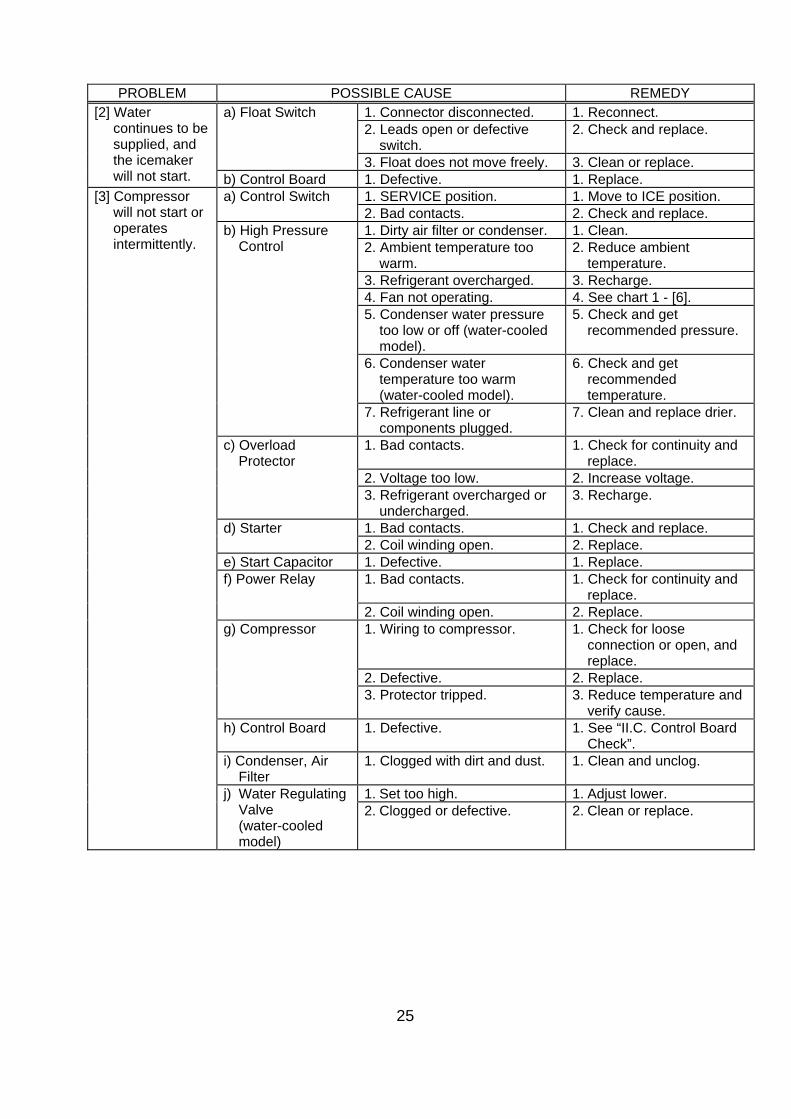
PROBLEM POSSIBLE CAUSE REMEDY [2] Water
continues to be supplied, and the icemaker will not start.
a) Float Switch 1. Connector disconnected. 1. Reconnect. 2. Leads open or defective
switch. 2. Check and replace.
3. Float does not move freely. 3. Clean or replace. b) Control Board 1. Defective. 1. Replace.
[3] Compressor will not start or operates intermittently.
a) Control Switch 1. SERVICE position. 1. Move to ICE position. 2. Bad contacts. 2. Check and replace.
b) High Pressure Control
1. Dirty air filter or condenser. 1. Clean. 2. Ambient temperature too
warm. 2. Reduce ambient
temperature. 3. Refrigerant overcharged. 3. Recharge. 4. Fan not operating. 4. See chart 1 - [6]. 5. Condenser water pressure
too low or off (water-cooled model).
5. Check and get recommended pressure.
6. Condenser water temperature too warm (water-cooled model).
6. Check and get recommended temperature.
7. Refrigerant line or components plugged.
7. Clean and replace drier.
c) Overload Protector
1. Bad contacts. 1. Check for continuity and replace.
2. Voltage too low. 2. Increase voltage. 3. Refrigerant overcharged or
undercharged. 3. Recharge.
d) Starter 1. Bad contacts. 1. Check and replace. 2. Coil winding open. 2. Replace.
e) Start Capacitor 1. Defective. 1. Replace. f) Power Relay 1. Bad contacts. 1. Check for continuity and
replace. 2. Coil winding open. 2. Replace.
g) Compressor 1. Wiring to compressor. 1. Check for loose connection or open, and replace.
2. Defective. 2. Replace. 3. Protector tripped. 3. Reduce temperature and
verify cause. h) Control Board 1. Defective. 1. See “II.C. Control Board
Check”. i) Condenser, Air
Filter 1. Clogged with dirt and dust. 1. Clean and unclog.
j) Water Regulating Valve (water-cooled model)
1. Set too high. 1. Adjust lower. 2. Clogged or defective. 2. Clean or replace.
26
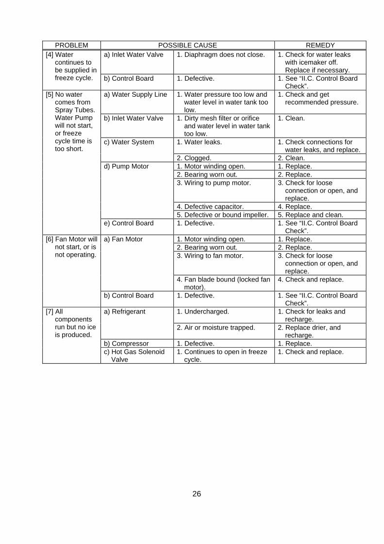
PROBLEM POSSIBLE CAUSE REMEDY [4] Water
continues to be supplied in freeze cycle.
a) Inlet Water Valve 1. Diaphragm does not close. 1. Check for water leaks with icemaker off. Replace if necessary.
b) Control Board 1. Defective. 1. See “II.C. Control Board Check”.
[5] No water comes from Spray Tubes. Water Pump will not start, or freeze cycle time is too short.
a) Water Supply Line 1. Water pressure too low and water level in water tank too low.
1. Check and get recommended pressure.
b) Inlet Water Valve 1. Dirty mesh filter or orifice and water level in water tank too low.
1. Clean.
c) Water System 1. Water leaks. 1. Check connections for water leaks, and replace.
2. Clogged. 2. Clean. d) Pump Motor 1. Motor winding open. 1. Replace.
2. Bearing worn out. 2. Replace. 3. Wiring to pump motor. 3. Check for loose
connection or open, and replace.
4. Defective capacitor. 4. Replace. 5. Defective or bound impeller. 5. Replace and clean.
e) Control Board 1. Defective. 1. See “II.C. Control Board Check”.
[6] Fan Motor will not start, or is not operating.
a) Fan Motor 1. Motor winding open. 1. Replace. 2. Bearing worn out. 2. Replace. 3. Wiring to fan motor. 3. Check for loose
connection or open, and replace.
4. Fan blade bound (locked fan motor).
4. Check and replace.
b) Control Board 1. Defective. 1. See “II.C. Control Board Check”.
[7] All components run but no ice is produced.
a) Refrigerant 1. Undercharged. 1. Check for leaks and recharge.
2. Air or moisture trapped. 2. Replace drier, and recharge.
b) Compressor 1. Defective. 1. Replace. c) Hot Gas Solenoid
Valve 1. Continues to open in freeze
cycle. 1. Check and replace.
27
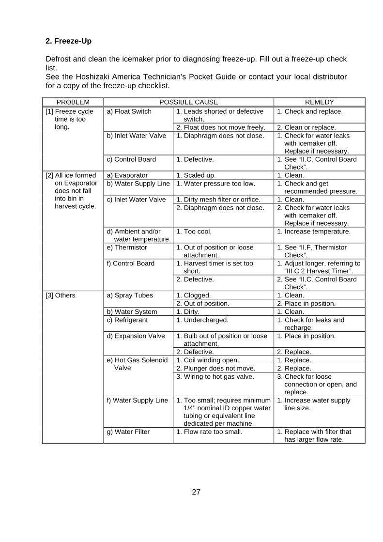
2. Freeze-Up Defrost and clean the icemaker prior to diagnosing freeze-up. Fill out a freeze-up check list. See the Hoshizaki America Technician’s Pocket Guide or contact your local distributor for a copy of the freeze-up checklist.
PROBLEM POSSIBLE CAUSE REMEDY [1] Freeze cycle
time is too long.
a) Float Switch 1. Leads shorted or defective switch.
1. Check and replace.
2. Float does not move freely. 2. Clean or replace. b) Inlet Water Valve 1. Diaphragm does not close. 1. Check for water leaks
with icemaker off. Replace if necessary.
c) Control Board 1. Defective. 1. See “II.C. Control Board Check”.
[2] All ice formed on Evaporator does not fall into bin in harvest cycle.
a) Evaporator 1. Scaled up. 1. Clean. b) Water Supply Line 1. Water pressure too low. 1. Check and get
recommended pressure. c) Inlet Water Valve 1. Dirty mesh filter or orifice. 1. Clean.
2. Diaphragm does not close. 2. Check for water leaks with icemaker off. Replace if necessary.
d) Ambient and/or water temperature
1. Too cool. 1. Increase temperature.
e) Thermistor 1. Out of position or loose attachment.
1. See “II.F. Thermistor Check”.
f) Control Board 1. Harvest timer is set too short.
1. Adjust longer, referring to “III.C.2 Harvest Timer”.
2. Defective. 2. See “II.C. Control Board Check”.
[3] Others a) Spray Tubes 1. Clogged. 1. Clean. 2. Out of position. 2. Place in position.
b) Water System 1. Dirty. 1. Clean. c) Refrigerant 1. Undercharged. 1. Check for leaks and
recharge. d) Expansion Valve 1. Bulb out of position or loose
attachment. 1. Place in position.
2. Defective. 2. Replace. e) Hot Gas Solenoid
Valve 1. Coil winding open. 1. Replace. 2. Plunger does not move. 2. Replace. 3. Wiring to hot gas valve. 3. Check for loose
connection or open, and replace.
f) Water Supply Line 1. Too small; requires minimum 1/4" nominal ID copper water tubing or equivalent line dedicated per machine.
1. Increase water supply line size.
g) Water Filter 1. Flow rate too small. 1. Replace with filter that has larger flow rate.
28
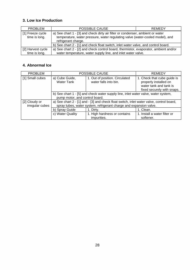
3. Low Ice Production
PROBLEM POSSIBLE CAUSE REMEDY [1] Freeze cycle
time is long. a) See chart 1 - [3] and check dirty air filter or condenser, ambient or water
temperature, water pressure, water regulating valve (water-cooled model), and refrigerant charge.
b) See chart 2 - [1] and check float switch, inlet water valve, and control board. [2] Harvest cycle
time is long. a) See chart 2 - [2] and check control board, thermistor, evaporator, ambient and/or
water temperature, water supply line, and inlet water valve. 4. Abnormal Ice
PROBLEM POSSIBLE CAUSE REMEDY [1] Small cubes a) Cube Guide,
Water Tank 1. Out of position. Circulated
water falls into bin. 1. Check that cube guide is
properly installed on water tank and tank is fixed securely with snaps.
b) See chart 1 - [5] and check water supply line, inlet water valve, water system, pump motor, and control board.
[2] Cloudy or irregular cubes
a) See chart 2 - [1] and - [3] and check float switch, inlet water valve, control board, spray tubes, water system, refrigerant charge and expansion valve.
b) Spray Guide 1. Dirty. 1. Clean. c) Water Quality 1. High hardness or contains
impurities. 1. Install a water filter or
softener.
29
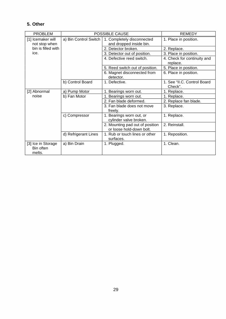
5. Other
PROBLEM POSSIBLE CAUSE REMEDY [1] Icemaker will
not stop when bin is filled with ice.
a) Bin Control Switch 1. Completely disconnected and dropped inside bin.
1. Place in position.
2. Detector broken. 2. Replace. 3. Detector out of position. 3. Place in position. 4. Defective reed switch. 4. Check for continuity and
replace. 5. Reed switch out of position. 5. Place in position. 6. Magnet disconnected from
detector. 6. Place in position.
b) Control Board 1. Defective. 1. See “II.C. Control Board Check”.
[2] Abnormal noise
a) Pump Motor 1. Bearings worn out. 1. Replace. b) Fan Motor 1. Bearings worn out. 1. Replace.
2. Fan blade deformed. 2. Replace fan blade. 3. Fan blade does not move
freely. 3. Replace.
c) Compressor 1. Bearings worn out, or cylinder valve broken.
1. Replace.
2. Mounting pad out of position or loose hold-down bolt.
2. Reinstall.
d) Refrigerant Lines 1. Rub or touch lines or other surfaces.
1. Reposition.
[3] Ice in Storage Bin often melts.
a) Bin Drain 1. Plugged. 1. Clean.
30
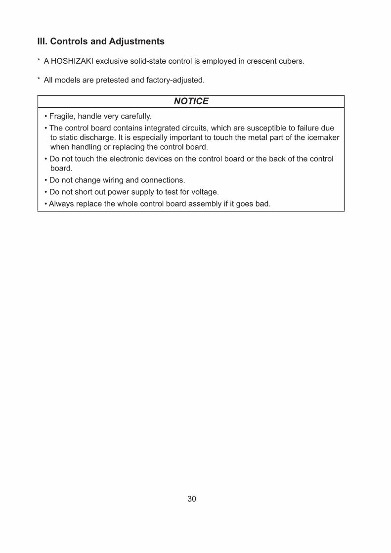
III. Controls and Adjustments
* A HOSHIZAKI exclusive solid-state control is employed in crescent cubers.
* All models are pretested and factory-adjusted.
NOTICE• Fragile, handle very carefully.• The control board contains integrated circuits, which are susceptible to failure due
to static discharge. It is especially important to touch the metal part of the icemaker when handling or replacing the control board.
• Do not touch the electronic devices on the control board or the back of the control board.
• Do not change wiring and connections.• Do not short out power supply to test for voltage.• Always replace the whole control board assembly if it goes bad.
31
A. Control Board Layout
16
"H" Control BoardPart Number P00013-0
"H" Control Board
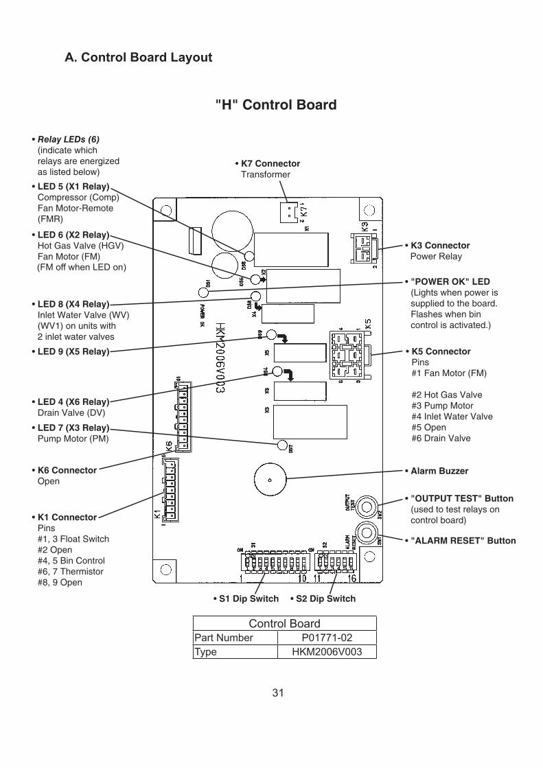
1. Control Board Layout
• "OUTPUT TEST" Button(used to test relays on control board)
• K6 ConnectorOpen
• K1 Connector Pins#1, 3 Float Switch# Open#4, 5 Bin Control#6, 7 Thermistor#8, 9 Open
• "ALARM RESET" Button
• S1 Dip Switch
• "POWER OK" LED(Lights when power is supplied to the board. Flashes when bin control is activated.)
• Relay LEDs (6)(indicate which relays are energized as listed below)
• LED 5 (X1 Relay)Compressor (Comp)Fan Motor-Remote (FMR)
• LED 4 (X6 Relay)Drain Valve (DV)
• LED 8 (X4 Relay)Inlet Water Valve (WV)(WV1) on units with inlet water valves
• K7 ConnectorTransformer
• K3 ConnectorMagnetic Contactor
• LED 7 (X3 Relay)Pump Motor (PM)
• LED 6 (X2 Relay)Hot Gas Valve (HGV)Fan Motor (FM) Liquid Line Valve (LLV)(FM and LLV off when LED on)
• LED 9 (X5 Relay)Inlet Water Valve (WV) on units with inlet water valves
• K5 Connector Pins#1 Fan Motor (FM) Liquid Line Valve (LLV)# Hot Gas Valve#3 Pump Motor#4 Inlet Water Valve#5 Open#6 Drain Valve
• S2 Dip Switch
• Alarm Buzzer
(FM off when LED on)Power Relay
Control BoardPart Number P01771-02Type HKM2006V003
32
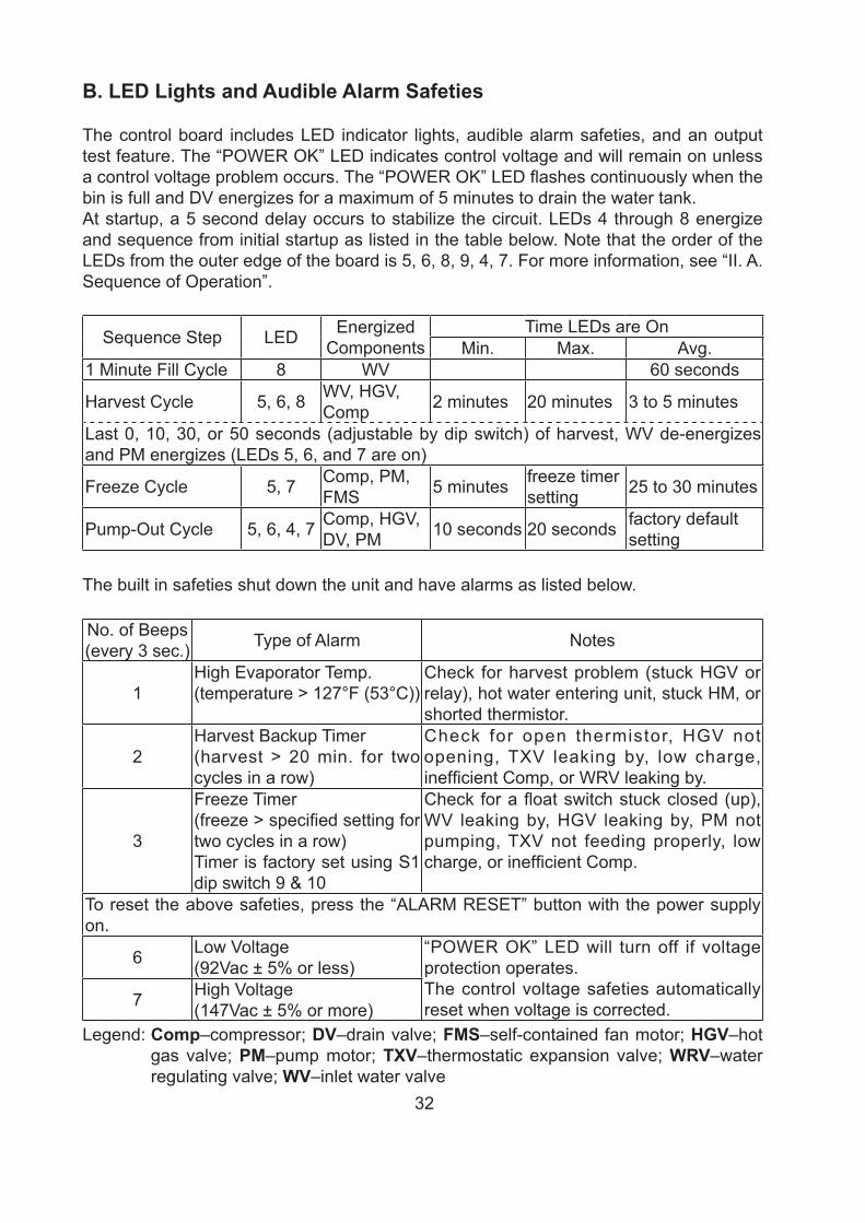
B. LED Lights and Audible Alarm Safeties
The control board includes LED indicator lights, audible alarm safeties, and an output test feature. The “POWER OK” LED indicates control voltage and will remain on unless a control voltage problem occurs. The “POWER OK” LED flashes continuously when the bin is full and DV energizes for a maximum of 5 minutes to drain the water tank.At startup, a 5 second delay occurs to stabilize the circuit. LEDs 4 through 8 energize and sequence from initial startup as listed in the table below. Note that the order of the LEDs from the outer edge of the board is 5, 6, 8, 9, 4, 7. For more information, see “II. A. Sequence of Operation”.
Sequence Step LED Energized Components
Time LEDs are OnMin. Max. Avg.
1 Minute Fill Cycle 8 WV 60 seconds
Harvest Cycle 5, 6, 8 WV, HGV, Comp 2 minutes 20 minutes 3 to 5 minutes
Last 0, 10, 30, or 50 seconds (adjustable by dip switch) of harvest, WV de-energizes and PM energizes (LEDs 5, 6, and 7 are on)
Freeze Cycle 5, 7 Comp, PM, FMS 5 minutes freeze timer
setting 25 to 30 minutes
Pump-Out Cycle 5, 6, 4, 7 Comp, HGV, DV, PM 10 seconds 20 seconds factory default
setting
The built in safeties shut down the unit and have alarms as listed below.
No. of Beeps (every 3 sec.) Type of Alarm Notes
1High Evaporator Temp.(temperature > 127°F (53°C))
Check for harvest problem (stuck HGV or relay), hot water entering unit, stuck HM, or shorted thermistor.
2Harvest Backup Timer(harvest > 20 min. for two cycles in a row)
Check for open thermistor, HGV not opening, TXV leaking by, low charge, inefficient Comp, or WRV leaking by.
3
Freeze Timer(freeze > specified setting for two cycles in a row)Timer is factory set using S1 dip switch 9 & 10
Check for a float switch stuck closed (up), WV leaking by, HGV leaking by, PM not pumping, TXV not feeding properly, low charge, or inefficient Comp.
To reset the above safeties, press the “ALARM RESET” button with the power supply on.
6 Low Voltage(92Vac ± 5% or less)
“POWER OK” LED will turn off if voltage protection operates.The control voltage safeties automatically reset when voltage is corrected.7 High Voltage
(147Vac ± 5% or more)Legend: Comp–compressor; DV–drain valve; FMS–self-contained fan motor; HGV–hot
gas valve; PM–pump motor; TXV–thermostatic expansion valve; WRV–water regulating valve; WV–inlet water valve
33
C. Settings and Adjustments
NOTICEDip switches are factory set. Failure to maintain factory settings may adversely affect performance and warranty coverage.
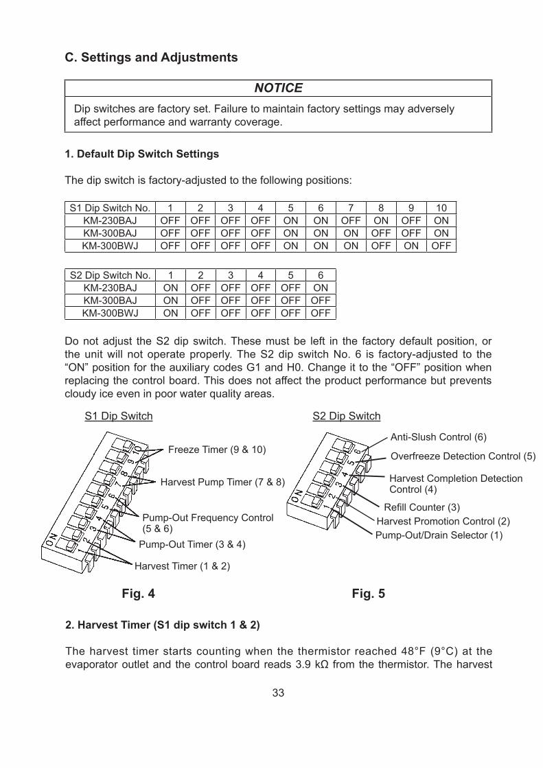
1. Default Dip Switch Settings
The dip switch is factory-adjusted to the following positions:
S1 Dip Switch No. 1 2 3 4 5 6 7 8 9 10KM-230BAJ OFF OFF OFF OFF ON ON OFF ON OFF ONKM-300BAJ OFF OFF OFF OFF ON ON ON OFF OFF ONKM-300BWJ OFF OFF OFF OFF ON ON ON OFF ON OFF
S2 Dip Switch No. 1 2 3 4 5 6KM-230BAJ ON OFF OFF OFF OFF ONKM-300BAJ ON OFF OFF OFF OFF OFFKM-300BWJ ON OFF OFF OFF OFF OFF
Do not adjust the S2 dip switch. These must be left in the factory default position, or the unit will not operate properly. The S2 dip switch No. 6 is factory-adjusted to the “ON” position for the auxiliary codes G1 and H0. Change it to the “OFF” position when replacing the control board. This does not affect the product performance but prevents cloudy ice even in poor water quality areas.
Fig. 4 Fig. 5
Freeze Timer (9 & 10)
Harvest Pump Timer (7 & 8)
Pump-Out Frequency Control (5 & 6)
Pump-Out Timer (3 & 4)
Harvest Timer (1 & 2)
S1 Dip Switch S2 Dip Switch
Anti-Slush Control (6)
Harvest Completion Detection Control (4)
Harvest Promotion Control (2)
Overfreeze Detection Control (5)
Pump-Out/Drain Selector (1)
Refill Counter (3)
2. Harvest Timer (S1 dip switch 1 & 2)
The harvest timer starts counting when the thermistor reached 48°F (9°C) at the evaporator outlet and the control board reads 3.9 kΩ from the thermistor. The harvest
34
timer is factory set, and generally no adjustment is required. However, a setting longer than the factory setting may be advised in cases where the drain provided at harvest needs to be prolonged for extra cleaning. Before changing this setting, contact Hoshizaki Technical Support at 1-800-233-1940 for recommendations. Keep in mind that setting the harvest timer to a longer setting decreases 24-hour production.Note that the pump-out timer (S1 dip switch 3 & 4) acts in place of the harvest timer during cycles with a pump out. For details, see “III. C. 3. Pump-Out Timer (S1 dip switch 3 & 4).“Note: On models with a pump-out every cycle, the harvest timer is only relevant during
the initial harvest cycle since a pump out occurs every cycle there after.
Dip Switch Setting Time(seconds)No. 1 No. 2
OFF OFF 60ON OFF 90OFF ON 120ON ON 180
3. Pump-Out Timer (S1 dip switch 3 & 4)
When a pump-out is called for, the pump motor stops for 2 seconds, then the pump motor and drain valve energize. Water is removed from the bottom of the water tank and sent down the drain. The pump-out drains the water tank for the time determined by the pump-out timer. The pump-out timer also acts in place of the harvest timer during cycles with a pump-out. The pump-out timer is factory set, and generally no adjustment is required. The pump-out timer control can be set to pump-out for 10 or 20 seconds.
Dip Switch Setting Time (seconds)No. 3 No. 4 T1 T2OFF OFF 10 120ON OFF 20 160OFF ON 20 120ON ON 20 180
T1: Time to drain the water tankT2: Harvest timer at pump-out
4. Pump-Out Frequency Control (S1 dip switch 5 & 6)
The water tank drains at the frequency set by the pump-out frequency control.The pump-out frequency control is factory-adjusted to drain the water tank every 10 cycles, and no adjustment is required. However, where water quality is bad and the icemaker needs a pump-out more often, the pump-out frequency can be adjusted as shown in the table below.
35
Dip Switch Setting FrequencyNo. 5 No. 6OFF OFF every cycleON OFF every 2 cyclesOFF ON every 5 cyclesON ON every 10 cycles
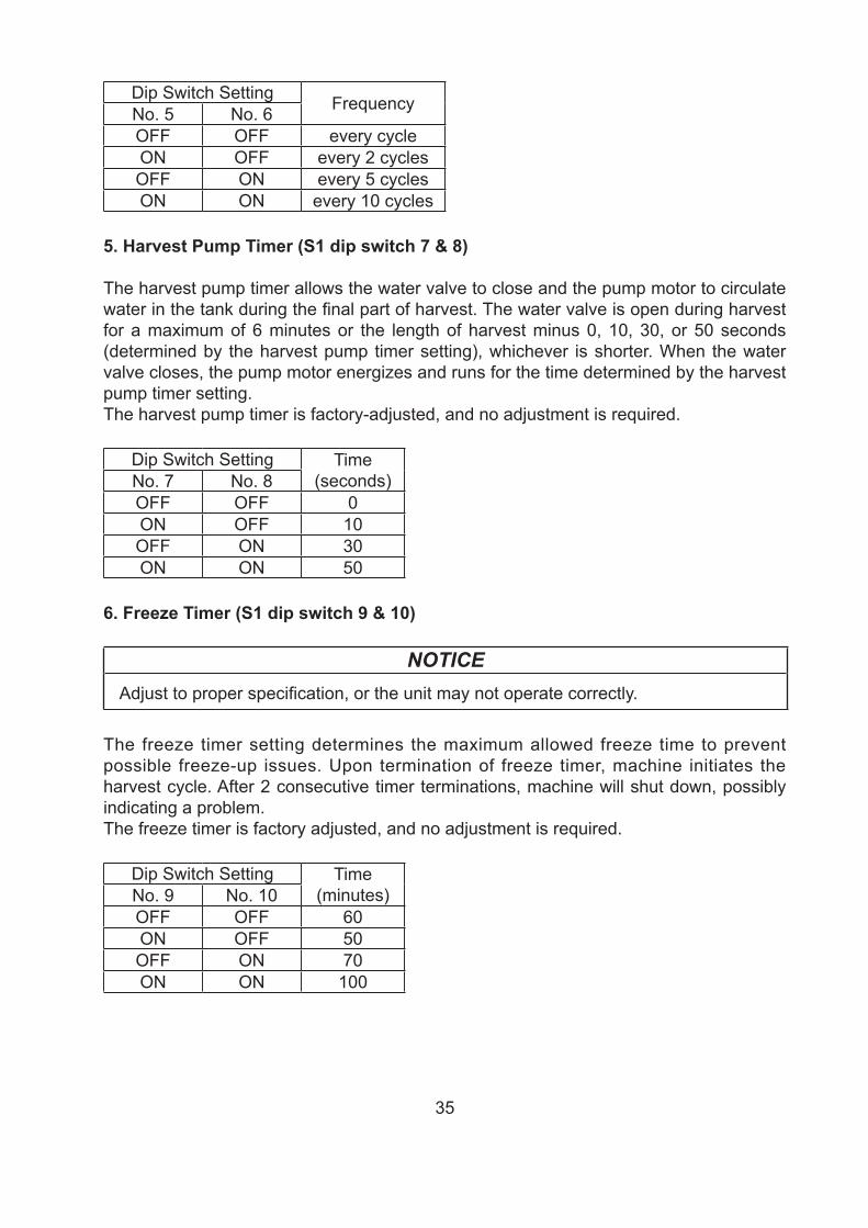
5. Harvest Pump Timer (S1 dip switch 7 & 8)
The harvest pump timer allows the water valve to close and the pump motor to circulate water in the tank during the final part of harvest. The water valve is open during harvest for a maximum of 6 minutes or the length of harvest minus 0, 10, 30, or 50 seconds (determined by the harvest pump timer setting), whichever is shorter. When the water valve closes, the pump motor energizes and runs for the time determined by the harvest pump timer setting.The harvest pump timer is factory-adjusted, and no adjustment is required.
Dip Switch Setting Time(seconds)No. 7 No. 8
OFF OFF 0ON OFF 10OFF ON 30ON ON 50
6. Freeze Timer (S1 dip switch 9 & 10)
NOTICEAdjust to proper specification, or the unit may not operate correctly.
The freeze timer setting determines the maximum allowed freeze time to prevent possible freeze-up issues. Upon termination of freeze timer, machine initiates the harvest cycle. After 2 consecutive timer terminations, machine will shut down, possibly indicating a problem.The freeze timer is factory adjusted, and no adjustment is required.
Dip Switch Setting Time(minutes)No. 9 No. 10
OFF OFF 60ON OFF 50OFF ON 70ON ON 100
36
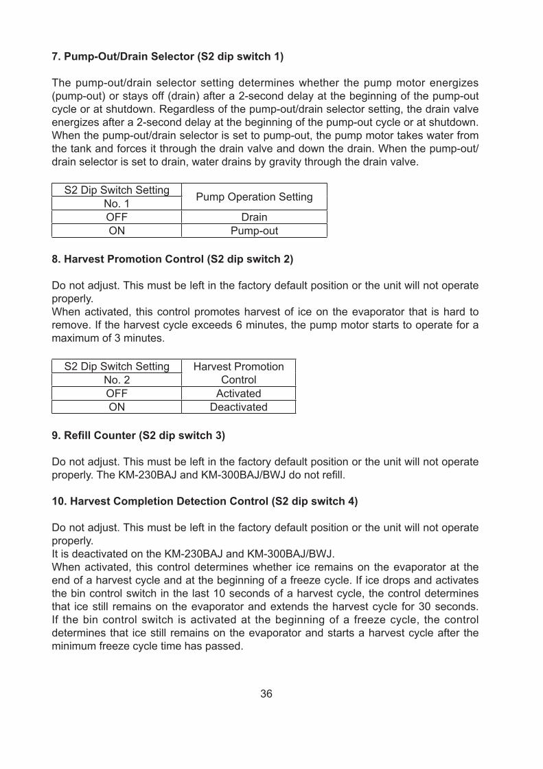
7. Pump-Out/Drain Selector (S2 dip switch 1)
The pump-out/drain selector setting determines whether the pump motor energizes (pump-out) or stays off (drain) after a 2-second delay at the beginning of the pump-out cycle or at shutdown. Regardless of the pump-out/drain selector setting, the drain valve energizes after a 2-second delay at the beginning of the pump-out cycle or at shutdown. When the pump-out/drain selector is set to pump-out, the pump motor takes water from the tank and forces it through the drain valve and down the drain. When the pump-out/drain selector is set to drain, water drains by gravity through the drain valve.
S2 Dip Switch Setting Pump Operation SettingNo. 1OFF DrainON Pump-out
8. Harvest Promotion Control (S2 dip switch 2)
Do not adjust. This must be left in the factory default position or the unit will not operate properly.When activated, this control promotes harvest of ice on the evaporator that is hard to remove. If the harvest cycle exceeds 6 minutes, the pump motor starts to operate for a maximum of 3 minutes.
S2 Dip Switch Setting Harvest Promotion ControlNo. 2
OFF ActivatedON Deactivated
9. Refill Counter (S2 dip switch 3)
Do not adjust. This must be left in the factory default position or the unit will not operate properly. The KM-230BAJ and KM-300BAJ/BWJ do not refill.
10. Harvest Completion Detection Control (S2 dip switch 4)
Do not adjust. This must be left in the factory default position or the unit will not operate properly.It is deactivated on the KM-230BAJ and KM-300BAJ/BWJ.When activated, this control determines whether ice remains on the evaporator at the end of a harvest cycle and at the beginning of a freeze cycle. If ice drops and activates the bin control switch in the last 10 seconds of a harvest cycle, the control determines that ice still remains on the evaporator and extends the harvest cycle for 30 seconds. If the bin control switch is activated at the beginning of a freeze cycle, the control determines that ice still remains on the evaporator and starts a harvest cycle after the minimum freeze cycle time has passed.
37
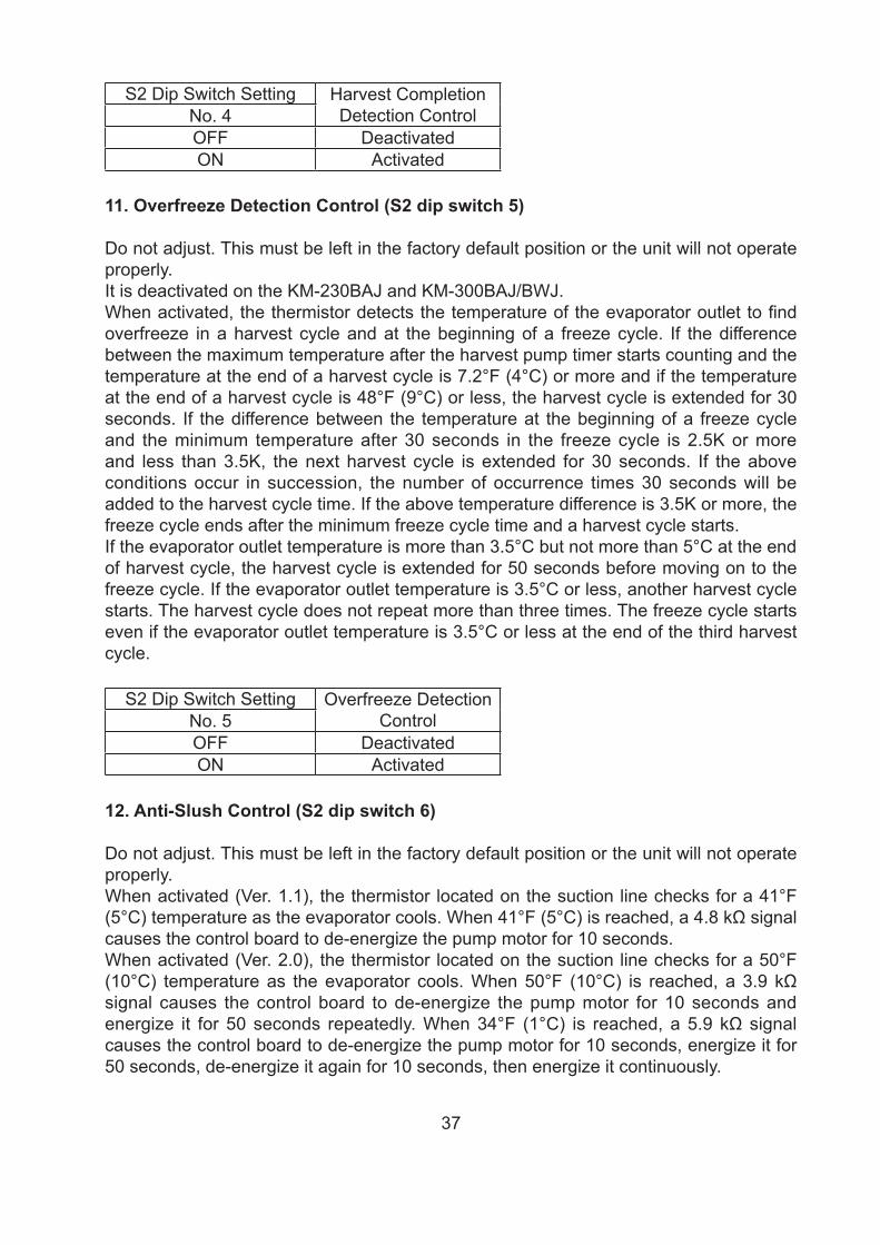
S2 Dip Switch Setting Harvest Completion Detection ControlNo. 4
OFF DeactivatedON Activated
11. Overfreeze Detection Control (S2 dip switch 5)
Do not adjust. This must be left in the factory default position or the unit will not operate properly.It is deactivated on the KM-230BAJ and KM-300BAJ/BWJ.When activated, the thermistor detects the temperature of the evaporator outlet to find overfreeze in a harvest cycle and at the beginning of a freeze cycle. If the difference between the maximum temperature after the harvest pump timer starts counting and the temperature at the end of a harvest cycle is 7.2°F (4°C) or more and if the temperature at the end of a harvest cycle is 48°F (9°C) or less, the harvest cycle is extended for 30 seconds. If the difference between the temperature at the beginning of a freeze cycle and the minimum temperature after 30 seconds in the freeze cycle is 2.5K or more and less than 3.5K, the next harvest cycle is extended for 30 seconds. If the above conditions occur in succession, the number of occurrence times 30 seconds will be added to the harvest cycle time. If the above temperature difference is 3.5K or more, the freeze cycle ends after the minimum freeze cycle time and a harvest cycle starts.If the evaporator outlet temperature is more than 3.5°C but not more than 5°C at the end of harvest cycle, the harvest cycle is extended for 50 seconds before moving on to the freeze cycle. If the evaporator outlet temperature is 3.5°C or less, another harvest cycle starts. The harvest cycle does not repeat more than three times. The freeze cycle starts even if the evaporator outlet temperature is 3.5°C or less at the end of the third harvest cycle.
S2 Dip Switch Setting Overfreeze Detection ControlNo. 5
OFF DeactivatedON Activated
12. Anti-Slush Control (S2 dip switch 6)
Do not adjust. This must be left in the factory default position or the unit will not operate properly.When activated (Ver. 1.1), the thermistor located on the suction line checks for a 41°F (5°C) temperature as the evaporator cools. When 41°F (5°C) is reached, a 4.8 kΩ signal causes the control board to de-energize the pump motor for 10 seconds.When activated (Ver. 2.0), the thermistor located on the suction line checks for a 50°F (10°C) temperature as the evaporator cools. When 50°F (10°C) is reached, a 3.9 kΩ signal causes the control board to de-energize the pump motor for 10 seconds and energize it for 50 seconds repeatedly. When 34°F (1°C) is reached, a 5.9 kΩ signal causes the control board to de-energize the pump motor for 10 seconds, energize it for 50 seconds, de-energize it again for 10 seconds, then energize it continuously.
38
S2 Dip Switch Setting Anti-Slush ControlNo. 6OFF Activated (Ver. 1.1)ON Activated (Ver. 2.0)
13. Control Board Replacement
The dip switches should be adjusted to the factory default settings as outlined in this manual.
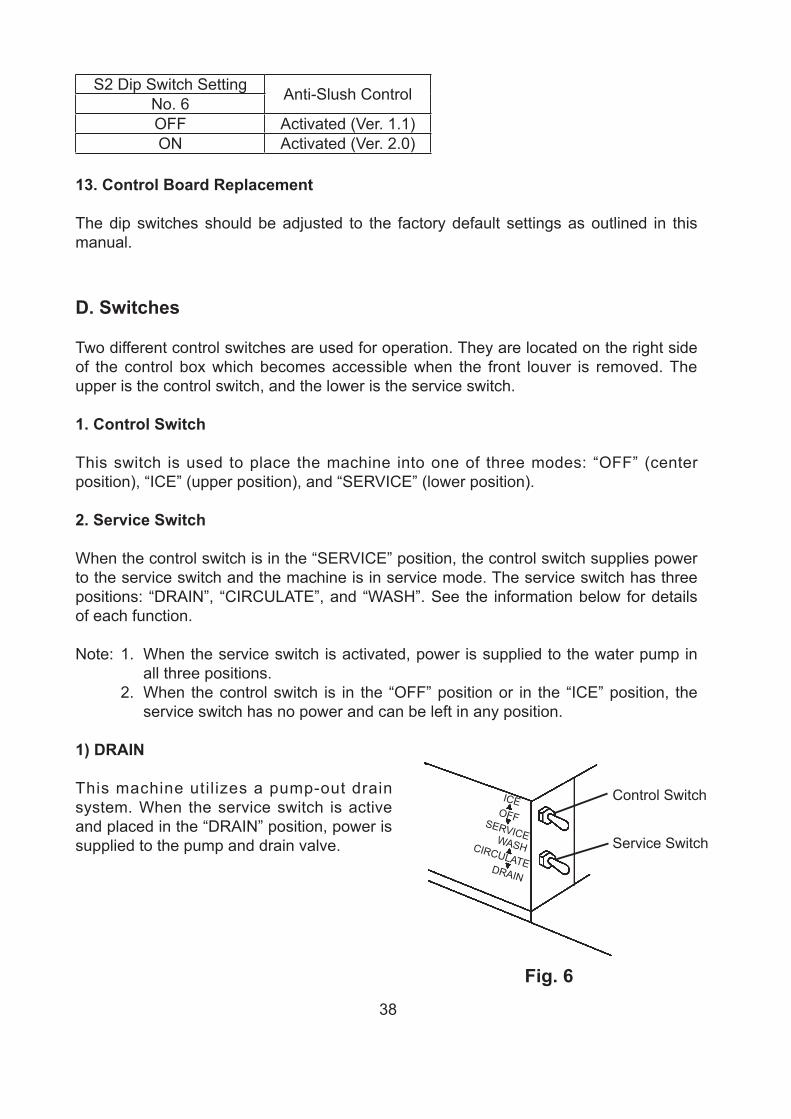
D. Switches
Two different control switches are used for operation. They are located on the right side of the control box which becomes accessible when the front louver is removed. The upper is the control switch, and the lower is the service switch.
1. Control Switch
This switch is used to place the machine into one of three modes: “OFF” (center position), “ICE” (upper position), and “SERVICE” (lower position).
2. Service Switch
When the control switch is in the “SERVICE” position, the control switch supplies power to the service switch and the machine is in service mode. The service switch has three positions: “DRAIN”, “CIRCULATE”, and “WASH”. See the information below for details of each function.
Note: 1. When the service switch is activated, power is supplied to the water pump in all three positions.
2. When the control switch is in the “OFF” position or in the “ICE” position, the service switch has no power and can be left in any position.
1) DRAIN
This machine util izes a pump-out drain system. When the service switch is active and placed in the “DRAIN” position, power is supplied to the pump and drain valve.
Fig. 6
Control Switch
Service SwitchSERVICE
ICEOFF
DRAIN
WASHCIRCULATE
39
2) CIRCULATE
When the service switch is active and placed in the “CIRCULATE” position, power is supplied to the pump only. This operation can be used to circulate cleaner for extended periods of time over the outside surface of the evaporator.
3) WASH
This machine utilizes a solenoid operated wash (bypass) valve. When the service switch is active and placed in the “WASH” position, power is supplied to the pump and cleaning valve. This operation is used to circulate cleaner and sanitizer over both the inside and outside of the evaporator.
40
IV. Refrigeration Circuit and Component Service Information
WARNING• This appliance should be diagnosed and repaired only by qualified service
personnel to reduce the risk of death, electric shock, serious injury, or fire. • To reduce the risk of electric shock, do not touch the control switch or plug with
damp hands. Make sure the control switch is in the "OFF" position before plugging in or unplugging the appliance.
• Move the control switch to the "OFF" position and unplug the appliance from the electrical outlet before servicing.
• CHOKING HAZARD: Ensure all components, fasteners, and thumbscrews are securely in place after any maintenance is done to the appliance. Make sure that none have fallen into the storage bin.
• Make sure all food zones in the icemaker and storage bin are clean after service.
A. Refrigeration Circuit Service Information
WARNING• Repairs requiring the refrigeration circuit to be opened must be performed by
properly trained and EPA-certified service personnel.• Use an electronic leak detector or soap bubbles to check for leaks. Add a trace of
refrigerant to the system (if using an electronic leak detector), and then raise the pressure using nitrogen gas (140 PSIG). Do not use R-404A as a mixture with pressurized air for leak testing.
NOTICE• Always recover the refrigerant and store it in an approved container. Do not
discharge the refrigerant into the atmosphere.• Do not leave the system open for longer than 15 min. when replacing or servicing
parts. The Polyol Ester (POE) oils used in R-404A applications can absorb moisture quickly. Therefore it is important to prevent moisture from entering the system when replacing or servicing parts.
• Always install a new drier every time the sealed refrigeration system is opened. Do not replace the drier until after all other repair or replacement has been made. Install the new drier with the arrow on the drier in the direction of the refrigerant flow.
• When brazing, protect the drier by using a wet cloth to prevent the drier from overheating. Do not allow the drier to exceed 250°F (121°C).
41
1. Refrigerant Recovery
The icemaker is provided with a low-side refrigerant access valve. Using proper refrigerant practices, recover the refrigerant from the access valve and store it in an approved container. Do not discharge the refrigerant into the atmosphere. After recovery is complete, install a proper, permanent high-side access valve.
2. Brazing
WARNING• R-404A itself is not flammable at atmospheric pressure and temperatures up to
176°F (80°C).• R-404A itself is not explosive or poisonous. However, when exposed to high
temperatures (open flames), R-404A can be decomposed to form hydrofluoric acid and carbonyl fluoride both of which are hazardous.
• Do not use silver alloy or copper alloy containing arsenic.
1) Braze all fittings while purging with nitrogen gas flowing at a pressure of 3 to 4 PSIG.Note: Because the pipes in the evaporator case are specially coated to resist
corrosion, it is important to make connections outside the evaporator case when possible. If it is necessary to braze inside the evaporator case, use sandpaper to remove the coating from the brazing connections before unbrazing the components.
NOTICE• Always install a new drier every time the sealed refrigeration system is opened. • Do not replace the drier until after all other repair or replacement has been made.
Install the new drier with the arrow on the drier in the direction of the refrigerant flow.
• When brazing, protect the drier by using a wet cloth to prevent the drier from overheating. Do not allow the drier to exceed 250°F (121°C).
2) Use an electronic leak detector or soap bubbles to check for leaks. Add a trace of refrigerant to the system (if using an electronic leak detector), and then raise the pressure using nitrogen gas (140 PSIG). Do not use R-404A as a mixture with pressurized air for leak testing.
3. Evacuation and Recharge (R-404A)1) Attach a vacuum pump to the system. Be sure to connect the charging hoses to
both the low-side access valve and the field-installed high-side access valve.
42
IMPORTANT
The vacuum level and vacuum pump may be the same as those for current refrigerants. However, the rubber hose and gauge manifold to be used for evacuation and refrigerant charge should be exclusively for POE oils.
2) Turn on the vacuum pump. Open the gauge manifold valves. Never allow the oil in the vacuum pump to flow backwards.
3) Allow the vacuum pump to pull down to a 29.9” Hg vacuum. Evacuating period depends on pump capacity.
4) Close the low-side valve and high-side valve on the gauge manifold.5) Disconnect the gauge manifold hose from the vacuum pump and attach it to
a refrigerant service cylinder. Remember to loosen the connection and purge the air from the hose. For the required refrigerant charge, see the nameplate. Hoshizaki recommends only virgin refrigerant or reclaimed refrigerant which meets AHRI Standard 700 (latest edition) be used.
6) A liquid charge is required when charging an R-404A system (to prevent fractionation). Place the service cylinder on the scales; if the service cylinder is not equipped with a dip tube, invert the service cylinder, then place it on the scales. Open the high-side valve on the gauge manifold.
7) Allow the system to charge with liquid until the proper charge weight is met.8) If necessary, add any remaining charge to the system through the low-side.
NOTICE! To prevent compressor damage, use a throttling valve or liquid dispensing device to add the remaining liquid charge through the low-side access valve with the appliance running.
9) Close the gauge manifold valves, then disconnect the gauge manifold hoses.10) Cap the access valves to prevent a possible leak.
B. Component Service Information
NOTICEWhen replacing a component listed below, see the notes to help ensure proper operation.
Component NotesCompressor Install a new start capacitor and start relay (if applicable).Thermostatic Expansion Valve
• Attach the thermostatic expansion valve bulb to the suction line in the same location as the previous bulb.
• The bulb should be between the 10 and 2 o'clock positions on the tube.
• Secure the bulb with the clamp and holder, then insulate it.
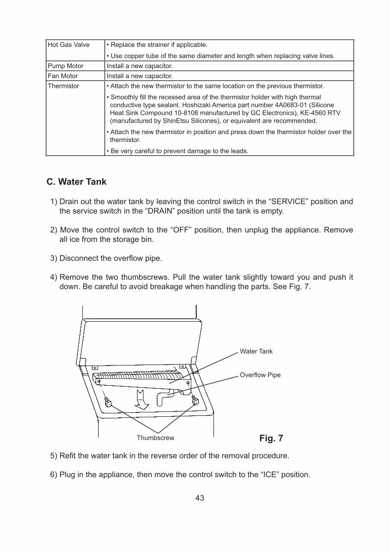
43
Fig. 7Thumbscrew
Water Tank
Overflow Pipe
Hot Gas Valve • Replace the strainer if applicable.
• Use copper tube of the same diameter and length when replacing valve lines.Pump Motor Install a new capacitor.Fan Motor Install a new capacitor.Thermistor • Attach the new thermistor to the same location on the previous thermistor.
• Smoothly fill the recessed area of the thermistor holder with high thermal conductive type sealant. Hoshizaki America part number 4A0683-01 (Silicone Heat Sink Compound 10-8108 manufactured by GC Electronics), KE-4560 RTV (manufactured by ShinEtsu Silicones), or equivalent are recommended.
• Attach the new thermistor in position and press down the thermistor holder over the thermistor.
• Be very careful to prevent damage to the leads.
C. Water Tank
1) Drain out the water tank by leaving the control switch in the “SERVICE” position and the service switch in the “DRAIN” position until the tank is empty.
2) Move the control switch to the “OFF” position, then unplug the appliance. Remove all ice from the storage bin.
3) Disconnect the overflow pipe.
4) Remove the two thumbscrews. Pull the water tank slightly toward you and push it down. Be careful to avoid breakage when handling the parts. See Fig. 7.
5) Refit the water tank in the reverse order of the removal procedure.
6) Plug in the appliance, then move the control switch to the “ICE” position.
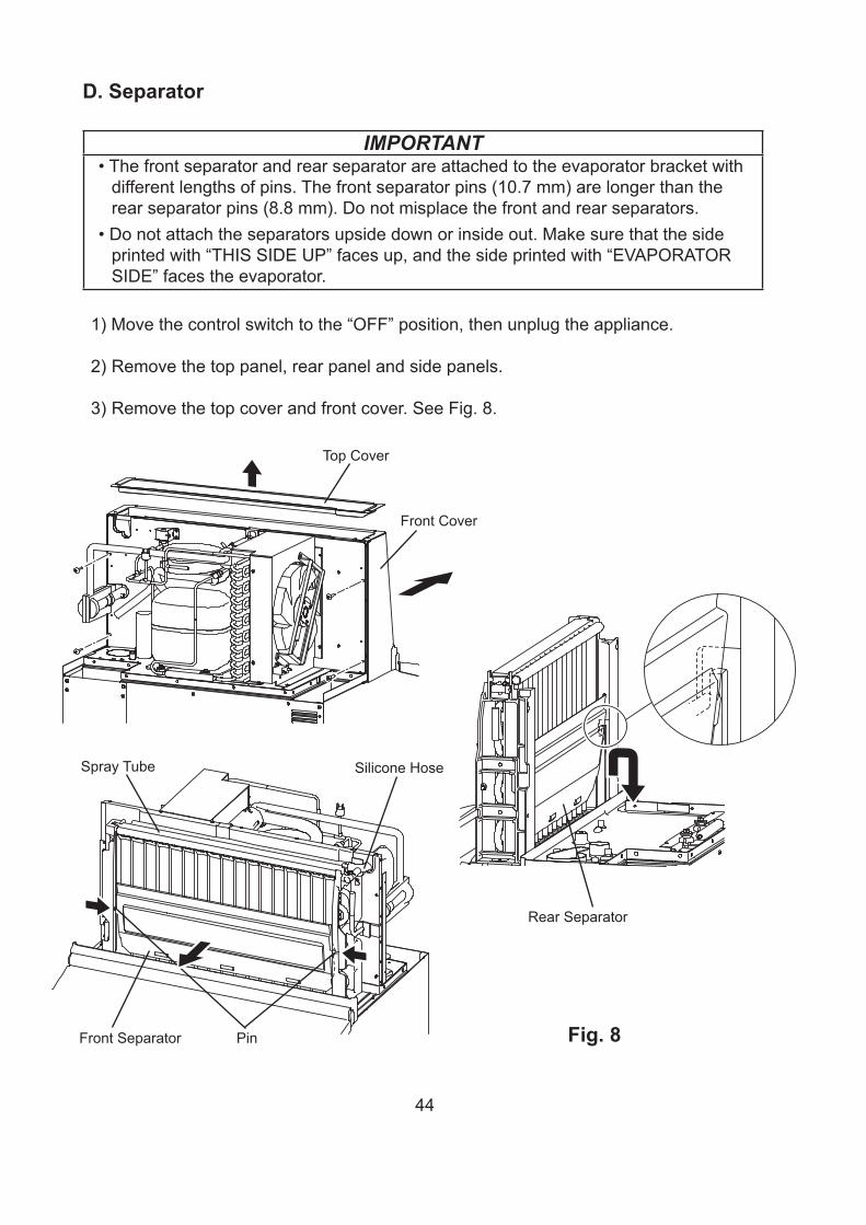
44
D. Separator
IMPORTANT• The front separator and rear separator are attached to the evaporator bracket with
different lengths of pins. The front separator pins (10.7 mm) are longer than the rear separator pins (8.8 mm). Do not misplace the front and rear separators.
• Do not attach the separators upside down or inside out. Make sure that the side printed with “THIS SIDE UP” faces up, and the side printed with “EVAPORATOR SIDE” faces the evaporator.
1) Move the control switch to the “OFF” position, then unplug the appliance.
2) Remove the top panel, rear panel and side panels.
3) Remove the top cover and front cover. See Fig. 8.
Fig. 8
Spray Tube
Front Separator Pin
Silicone Hose
Front Cover
Top Cover
Rear Separator
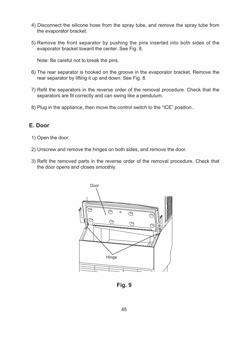
45
Fig. 9
Door
Hinge
4) Disconnect the silicone hose from the spray tube, and remove the spray tube from the evaporator bracket.
5) Remove the front separator by pushing the pins inserted into both sides of the evaporator bracket toward the center. See Fig. 8.
Note: Be careful not to break the pins.
6) The rear separator is hooked on the groove in the evaporator bracket. Remove the rear separator by lifting it up and down. See Fig. 8.
7) Refit the separators in the reverse order of the removal procedure. Check that the separators are fit correctly and can swing like a pendulum.
8) Plug in the appliance, then move the control switch to the “ICE” position..
E. Door
1) Open the door.
2) Unscrew and remove the hinges on both sides, and remove the door.
3) Refit the removed parts in the reverse order of the removal procedure. Check that the door opens and closes smoothly.
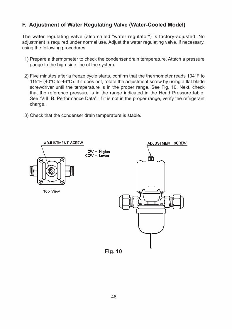
46
F. Adjustment of Water Regulating Valve (Water-Cooled Model)
The water regulating valve (also called "water regulator") is factory-adjusted. No adjustment is required under normal use. Adjust the water regulating valve, if necessary, using the following procedures.
1) Prepare a thermometer to check the condenser drain temperature. Attach a pressure gauge to the high-side line of the system.
2) Five minutes after a freeze cycle starts, confirm that the thermometer reads 104°F to 115°F (40°C to 46°C). If it does not, rotate the adjustment screw by using a flat blade screwdriver until the temperature is in the proper range. See Fig. 10. Next, check that the reference pressure is in the range indicated in the Head Pressure table. See “VIII. B. Performance Data”. If it is not in the proper range, verify the refrigerant charge.
3) Check that the condenser drain temperature is stable.
Fig. 10
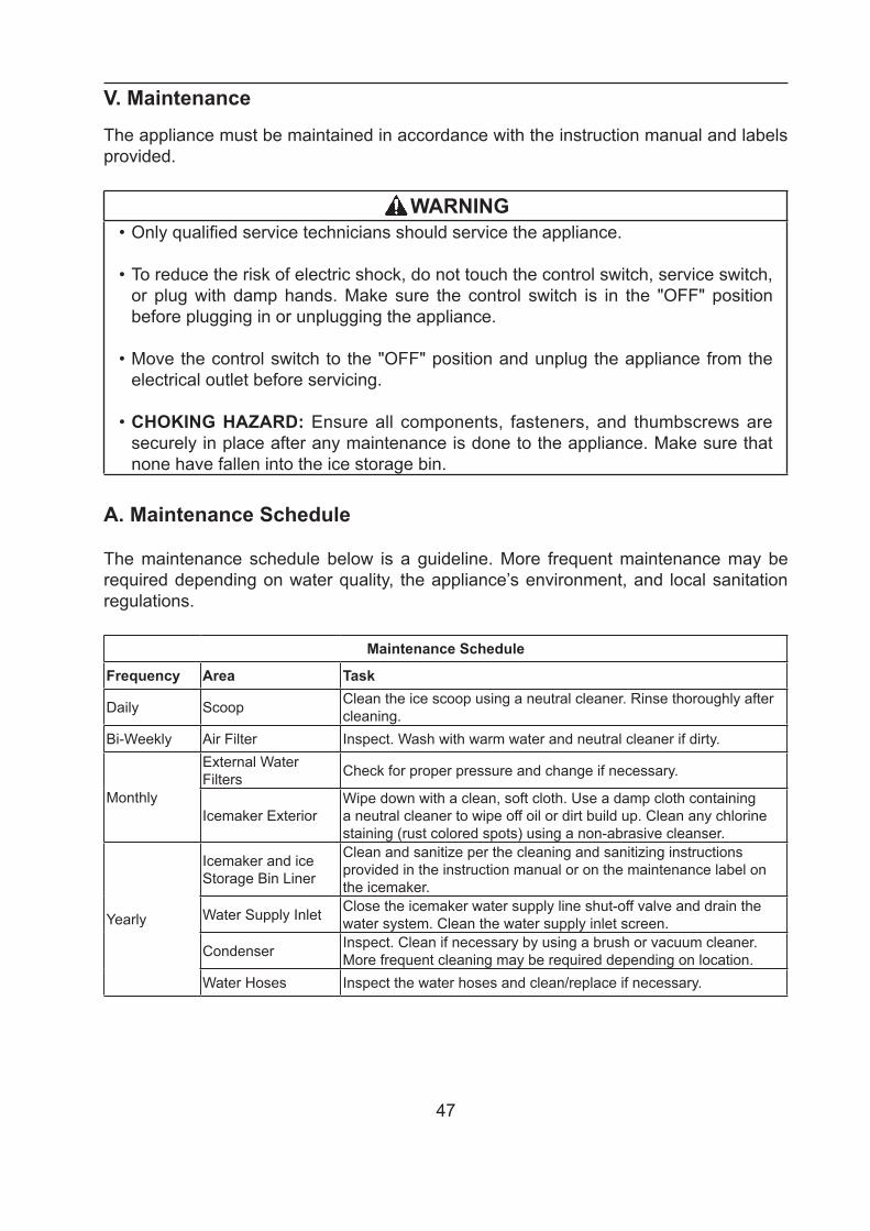
47
V. Maintenance
The appliance must be maintained in accordance with the instruction manual and labels provided.
WARNING• Only qualified service technicians should service the appliance.
• To reduce the risk of electric shock, do not touch the control switch, service switch, or plug with damp hands. Make sure the control switch is in the "OFF" position before plugging in or unplugging the appliance.
• Move the control switch to the "OFF" position and unplug the appliance from the electrical outlet before servicing.
• CHOKING HAZARD: Ensure all components, fasteners, and thumbscrews are securely in place after any maintenance is done to the appliance. Make sure that none have fallen into the ice storage bin.
A. Maintenance Schedule
The maintenance schedule below is a guideline. More frequent maintenance may be required depending on water quality, the appliance’s environment, and local sanitation regulations.
Maintenance Schedule
Frequency Area Task
Daily Scoop Clean the ice scoop using a neutral cleaner. Rinse thoroughly after cleaning.
Bi-Weekly Air Filter Inspect. Wash with warm water and neutral cleaner if dirty.
Monthly
External Water Filters Check for proper pressure and change if necessary.
Icemaker ExteriorWipe down with a clean, soft cloth. Use a damp cloth containing a neutral cleaner to wipe off oil or dirt build up. Clean any chlorine staining (rust colored spots) using a non-abrasive cleanser.
Yearly
Icemaker and ice Storage Bin Liner
Clean and sanitize per the cleaning and sanitizing instructions provided in the instruction manual or on the maintenance label on the icemaker.
Water Supply Inlet Close the icemaker water supply line shut-off valve and drain the water system. Clean the water supply inlet screen.
Condenser Inspect. Clean if necessary by using a brush or vacuum cleaner. More frequent cleaning may be required depending on location.
Water Hoses Inspect the water hoses and clean/replace if necessary.
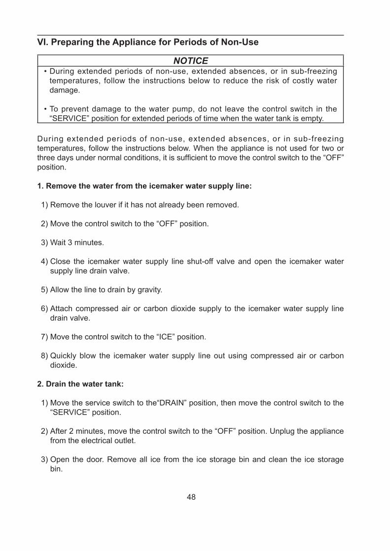
48
VI. Preparing the Appliance for Periods of Non-Use
NOTICE• During extended periods of non-use, extended absences, or in sub-freezing
temperatures, follow the instructions below to reduce the risk of costly water damage.
• To prevent damage to the water pump, do not leave the control switch in the “SERVICE” position for extended periods of time when the water tank is empty.
During extended periods of non-use, extended absences, or in sub-freezing temperatures, follow the instructions below. When the appliance is not used for two or three days under normal conditions, it is sufficient to move the control switch to the “OFF” position.
1. Remove the water from the icemaker water supply line:
1) Remove the louver if it has not already been removed.
2) Move the control switch to the “OFF” position.
3) Wait 3 minutes.
4) Close the icemaker water supply line shut-off valve and open the icemaker water supply line drain valve.
5) Allow the line to drain by gravity.
6) Attach compressed air or carbon dioxide supply to the icemaker water supply line drain valve.
7) Move the control switch to the “ICE” position.
8) Quickly blow the icemaker water supply line out using compressed air or carbon dioxide.
2. Drain the water tank:
1) Move the service switch to the“DRAIN” position, then move the control switch to the “SERVICE” position.
2) After 2 minutes, move the control switch to the “OFF” position. Unplug the appliance from the electrical outlet.
3) Open the door. Remove all ice from the ice storage bin and clean the ice storage bin.
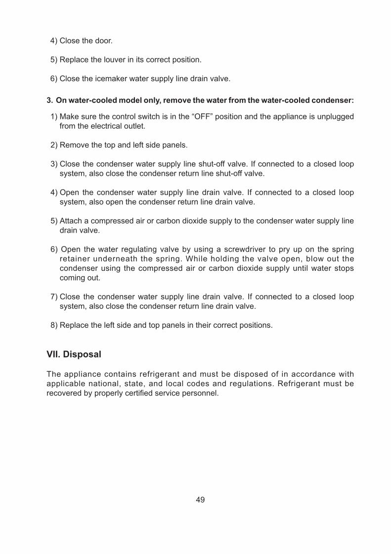
49
4) Close the door.
5) Replace the louver in its correct position.
6) Close the icemaker water supply line drain valve.
3. On water-cooled model only, remove the water from the water-cooled condenser:
1) Make sure the control switch is in the “OFF” position and the appliance is unplugged from the electrical outlet.
2) Remove the top and left side panels.
3) Close the condenser water supply line shut-off valve. If connected to a closed loop system, also close the condenser return line shut-off valve.
4) Open the condenser water supply line drain valve. If connected to a closed loop system, also open the condenser return line drain valve.
5) Attach a compressed air or carbon dioxide supply to the condenser water supply line drain valve.
6) Open the water regulating valve by using a screwdriver to pry up on the spring retainer underneath the spring. While holding the valve open, blow out the condenser using the compressed air or carbon dioxide supply until water stops coming out.
7) Close the condenser water supply line drain valve. If connected to a closed loop system, also close the condenser return line drain valve.
8) Replace the left side and top panels in their correct positions.
VII. Disposal
The appliance contains refrigerant and must be disposed of in accordance with applicable national, state, and local codes and regulations. Refrigerant must be recovered by properly certified service personnel.
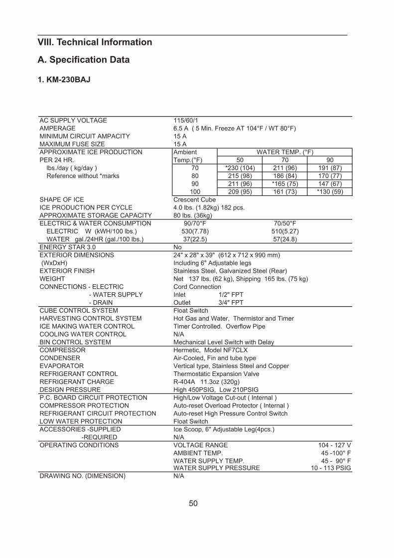
50
VIII. Technical Information
A. Specification Data
1. KM-230BAJSPECIFICATION NO. ISSUED:06/02/2017ITEM: HOSHIZAKI CRESCENT CUBER Revision 1MODEL: KM-230BAJ
AC SUPPLY VOLTAGE 115/60/1AMPERAGE 6.5 A ( 5 Min. Freeze AT 104°F / WT 80°F)MINIMUM CIRCUIT AMPACITY 15 AMAXIMUM FUSE SIZE 15 AAPPROXIMATE ICE PRODUCTION Ambient WATER TEMP. (°F)PER 24 HR. Temp.(°F) 50 70 90 lbs./day ( kg/day ) 70 *230 (104) 211 (96) 191 (87) Reference without *marks 80 215 (98) 186 (84) 170 (77)
90 211 (96) *165 (75) 147 (67)100 209 (95) 161 (73) *130 (59)
SHAPE OF ICE Crescent CubeICE PRODUCTION PER CYCLE 4.0 lbs. (1.82kg) 182 pcs.APPROXIMATE STORAGE CAPACITY 80 lbs. (36kg)ELECTRIC & WATER CONSUMPTION 90/70°F 70/50°F ELECTRIC W (kWH/100 lbs.) 530(7.78) 510(5.27) WATER gal./24HR (gal./100 lbs.) 37(22.5) 57(24.8)ENERGY STAR 3.0 NoEXTERIOR DIMENSIONS 24" x 28" x 39" (612 x 712 x 990 mm) (WxDxH) Including 6" Adjustable legsEXTERIOR FINISH Stainless Steel, Galvanized Steel (Rear) WEIGHT Net 137 lbs. (62 kg), Shipping 165 lbs. (75 kg)CONNECTIONS - ELECTRIC Cord Connection - WATER SUPPLY Inlet 1/2" FPT - DRAIN Outlet 3/4" FPTCUBE CONTROL SYSTEM Float SwitchHARVESTING CONTROL SYSTEM Hot Gas and Water, Thermistor and TimerICE MAKING WATER CONTROL Timer Controlled. Overflow PipeCOOLING WATER CONTROL N/ABIN CONTROL SYSTEM Mechanical Level Switch with DelayCOMPRESSOR Hermetic, Model NF7CLXCONDENSER Air-Cooled, Fin and tube typeEVAPORATOR Vertical type, Stainless Steel and CopperREFRIGERANT CONTROL Thermostatic Expansion ValveREFRIGERANT CHARGE R-404A 11.3oz (320g)DESIGN PRESSURE High 450PSIG, Low 210PSIGP.C. BOARD CIRCUIT PROTECTION High/Low Voltage Cut-out ( Internal )COMPRESSOR PROTECTION Auto-reset Overload Protector ( Internal )REFRIGERANT CIRCUIT PROTECTION Auto-reset High Pressure Control SwitchLOW WATER PROTECTION Float SwitchACCESSORIES -SUPPLIED Ice Scoop, 6" Adjustable Leg(4pcs.) -REQUIRED N/AOPERATING CONDITIONS VOLTAGE RANGE 104 - 127 V
AMBIENT TEMP. 45 -100° FWATER SUPPLY TEMP. 45 - 90° FWATER SUPPLY PRESSURE 10 - 113 PSIG
DRAWING NO. (DIMENSION) N/A
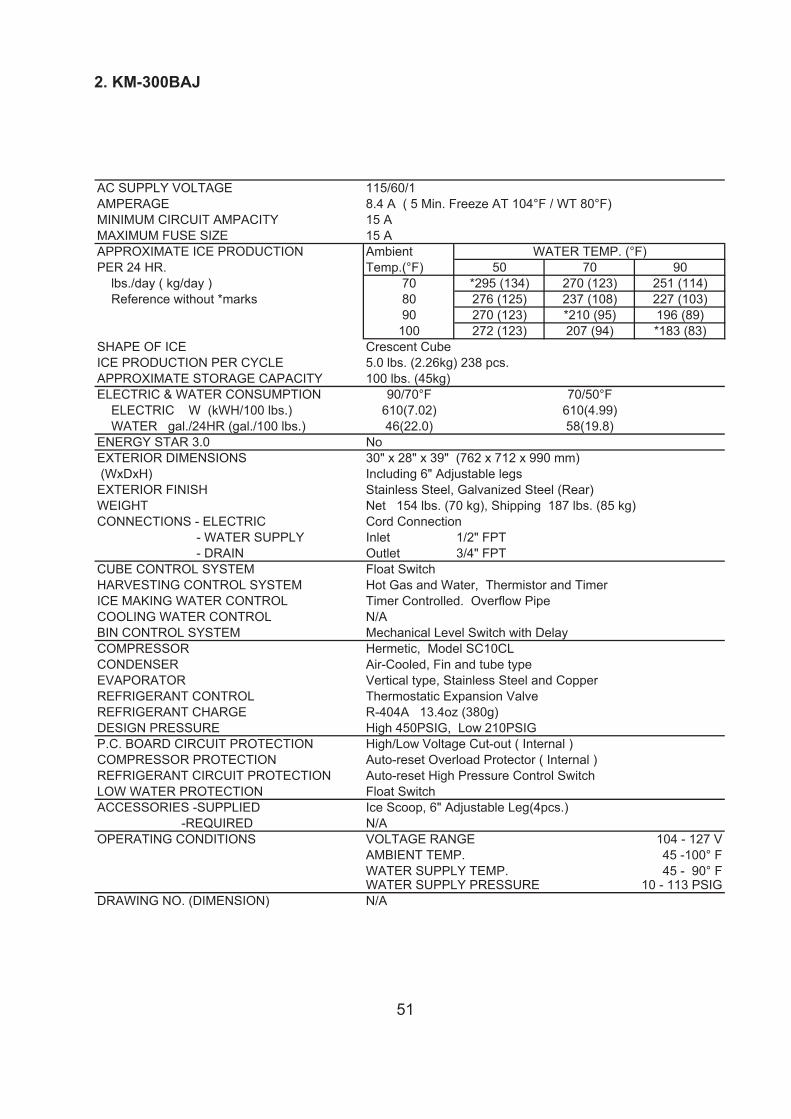
51
2. KM-300BAJ
SPECIFICATION NO. ISSUED:06/02/2017ITEM: HOSHIZAKI CRESCENT CUBER Revision 1MODEL: KM-300BAJ
AC SUPPLY VOLTAGE 115/60/1AMPERAGE 8.4 A ( 5 Min. Freeze AT 104°F / WT 80°F)MINIMUM CIRCUIT AMPACITY 15 AMAXIMUM FUSE SIZE 15 AAPPROXIMATE ICE PRODUCTION Ambient WATER TEMP. (°F)PER 24 HR. Temp.(°F) 50 70 90 lbs./day ( kg/day ) 70 *295 (134) 270 (123) 251 (114) Reference without *marks 80 276 (125) 237 (108) 227 (103)
90 270 (123) *210 (95) 196 (89)100 272 (123) 207 (94) *183 (83)
SHAPE OF ICE Crescent CubeICE PRODUCTION PER CYCLE 5.0 lbs. (2.26kg) 238 pcs.APPROXIMATE STORAGE CAPACITY 100 lbs. (45kg)ELECTRIC & WATER CONSUMPTION 90/70°F 70/50°F ELECTRIC W (kWH/100 lbs.) 610(7.02) 610(4.99) WATER gal./24HR (gal./100 lbs.) 46(22.0) 58(19.8)ENERGY STAR 3.0 NoEXTERIOR DIMENSIONS 30" x 28" x 39" (762 x 712 x 990 mm) (WxDxH) Including 6" Adjustable legsEXTERIOR FINISH Stainless Steel, Galvanized Steel (Rear) WEIGHT Net 154 lbs. (70 kg), Shipping 187 lbs. (85 kg)CONNECTIONS - ELECTRIC Cord Connection - WATER SUPPLY Inlet 1/2" FPT - DRAIN Outlet 3/4" FPTCUBE CONTROL SYSTEM Float SwitchHARVESTING CONTROL SYSTEM Hot Gas and Water, Thermistor and TimerICE MAKING WATER CONTROL Timer Controlled. Overflow PipeCOOLING WATER CONTROL N/ABIN CONTROL SYSTEM Mechanical Level Switch with DelayCOMPRESSOR Hermetic, Model SC10CLCONDENSER Air-Cooled, Fin and tube typeEVAPORATOR Vertical type, Stainless Steel and CopperREFRIGERANT CONTROL Thermostatic Expansion ValveREFRIGERANT CHARGE R-404A 13.4oz (380g)DESIGN PRESSURE High 450PSIG, Low 210PSIGP.C. BOARD CIRCUIT PROTECTION High/Low Voltage Cut-out ( Internal )COMPRESSOR PROTECTION Auto-reset Overload Protector ( Internal )REFRIGERANT CIRCUIT PROTECTION Auto-reset High Pressure Control SwitchLOW WATER PROTECTION Float SwitchACCESSORIES -SUPPLIED Ice Scoop, 6" Adjustable Leg(4pcs.) -REQUIRED N/AOPERATING CONDITIONS VOLTAGE RANGE 104 - 127 V
AMBIENT TEMP. 45 -100° FWATER SUPPLY TEMP. 45 - 90° FWATER SUPPLY PRESSURE 10 - 113 PSIG
DRAWING NO. (DIMENSION) N/A
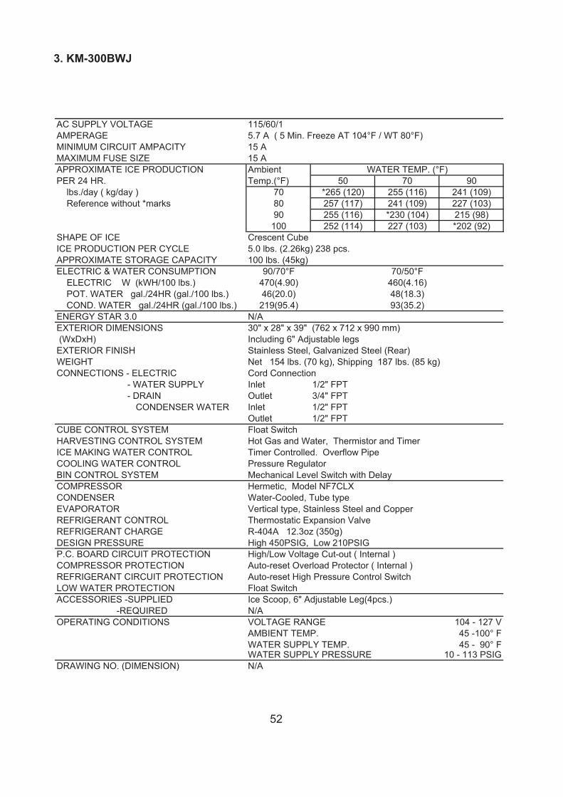
52
3. KM-300BWJ
SPECIFICATION NO. ISSUED:06/02/2017ITEM: HOSHIZAKI CRESCENT CUBER Revision 1MODEL: KM-300BWJ
AC SUPPLY VOLTAGE 115/60/1AMPERAGE 5.7 A ( 5 Min. Freeze AT 104°F / WT 80°F)MINIMUM CIRCUIT AMPACITY 15 AMAXIMUM FUSE SIZE 15 AAPPROXIMATE ICE PRODUCTION Ambient WATER TEMP. (°F)PER 24 HR. Temp.(°F) 50 70 90 lbs./day ( kg/day ) 70 *265 (120) 255 (116) 241 (109) Reference without *marks 80 257 (117) 241 (109) 227 (103)
90 255 (116) *230 (104) 215 (98)100 252 (114) 227 (103) *202 (92)
SHAPE OF ICE Crescent CubeICE PRODUCTION PER CYCLE 5.0 lbs. (2.26kg) 238 pcs.APPROXIMATE STORAGE CAPACITY 100 lbs. (45kg)ELECTRIC & WATER CONSUMPTION 90/70°F 70/50°F ELECTRIC W (kWH/100 lbs.) 470(4.90) 460(4.16) POT. WATER gal./24HR (gal./100 lbs.) 46(20.0) 48(18.3) COND. WATER gal./24HR (gal./100 lbs.) 219(95.4) 93(35.2)ENERGY STAR 3.0 N/AEXTERIOR DIMENSIONS 30" x 28" x 39" (762 x 712 x 990 mm) (WxDxH) Including 6" Adjustable legsEXTERIOR FINISH Stainless Steel, Galvanized Steel (Rear) WEIGHT Net 154 lbs. (70 kg), Shipping 187 lbs. (85 kg)CONNECTIONS - ELECTRIC Cord Connection - WATER SUPPLY Inlet 1/2" FPT - DRAIN Outlet 3/4" FPT
CONDENSER WATER Inlet 1/2" FPTOutlet 1/2" FPT
CUBE CONTROL SYSTEM Float SwitchHARVESTING CONTROL SYSTEM Hot Gas and Water, Thermistor and TimerICE MAKING WATER CONTROL Timer Controlled. Overflow PipeCOOLING WATER CONTROL Pressure RegulatorBIN CONTROL SYSTEM Mechanical Level Switch with DelayCOMPRESSOR Hermetic, Model NF7CLXCONDENSER Water-Cooled, Tube typeEVAPORATOR Vertical type, Stainless Steel and CopperREFRIGERANT CONTROL Thermostatic Expansion ValveREFRIGERANT CHARGE R-404A 12.3oz (350g)DESIGN PRESSURE High 450PSIG, Low 210PSIGP.C. BOARD CIRCUIT PROTECTION High/Low Voltage Cut-out ( Internal )COMPRESSOR PROTECTION Auto-reset Overload Protector ( Internal )REFRIGERANT CIRCUIT PROTECTION Auto-reset High Pressure Control SwitchLOW WATER PROTECTION Float SwitchACCESSORIES -SUPPLIED Ice Scoop, 6" Adjustable Leg(4pcs.) -REQUIRED N/AOPERATING CONDITIONS VOLTAGE RANGE 104 - 127 V
AMBIENT TEMP. 45 -100° FWATER SUPPLY TEMP. 45 - 90° FWATER SUPPLY PRESSURE 10 - 113 PSIG
DRAWING NO. (DIMENSION) N/A
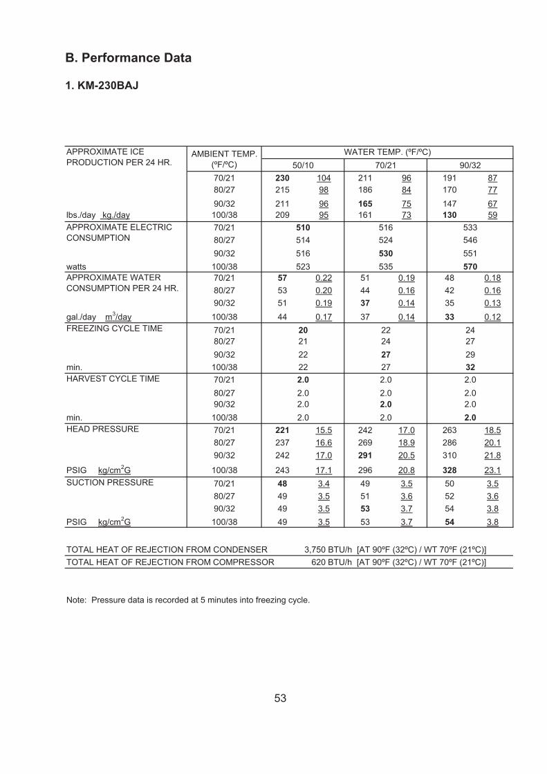
53
PERFORMANCE DATA ISSUED:06/02/2017ITEM: HOSHIZAKI CRESCENT CUBERMODEL: KM-230BAJ
70/21 230 104 211 96 191 8780/27 215 98 186 84 170 7790/32 211 96 165 75 147 67
lbs./day kg./day 100/38 209 95 161 73 130 5970/2180/2790/32
watts 100/3870/21 57 0.22 51 0.19 48 0.1880/27 53 0.20 44 0.16 42 0.1690/32 51 0.19 37 0.14 35 0.13
gal./day m3/day 100/38 44 0.17 37 0.14 33 0.1270/2180/2790/32
min. 100/3870/2180/2790/32
min. 100/3870/21 221 15.5 242 17.0 263 18.580/27 237 16.6 269 18.9 286 20.190/32 242 17.0 291 20.5 310 21.8
PSIG kg/cm2G 100/38 243 17.1 296 20.8 328 23.170/21 48 3.4 49 3.5 50 3.580/27 49 3.5 51 3.6 52 3.690/32 49 3.5 53 3.7 54 3.8
PSIG kg/cm2G 100/38 49 3.5 53 3.7 54 3.8
Note: Pressure data is recorded at 5 minutes into freezing cycle.
We reserve the right to make changes in specifications and design without prior notice.
212224
2.0
2.0
2.0
2.02.02.0
2.0
20
APPROXIMATE ICEPRODUCTION PER 24 HR.
APPROXIMATE ELECTRICCONSUMPTION
APPROXIMATE WATERCONSUMPTION PER 24 HR.
FREEZING CYCLE TIME
WATER TEMP. (ºF/ºC)AMBIENT TEMP.(ºF/ºC) 50/10 70/21 90/32
523
516524530535
510514516
24272932
533546551570
272222
27
2.0
SUCTION PRESSURE
HARVEST CYCLE TIME
HEAD PRESSURE
2.02.0
2.0 2.0
APPROVED CHECKED WRITTEN
K.Yamaoka2/Jun/2015
TOTAL HEAT OF REJECTION FROM CONDENSER 3,750 BTU/h [AT 90ºF (32ºC) / WT 70ºF (21ºC)]TOTAL HEAT OF REJECTION FROM COMPRESSOR 620 BTU/h [AT 90ºF (32ºC) / WT 70ºF (21ºC)]
\\Hzassv01\manual_data\海外【村瀬】\データ\Icemaker\KM\KM\原稿\KM-230,300B_J\201706\230BAJ SPEC & PERF.xls
B. Performance Data
1. KM-230BAJ
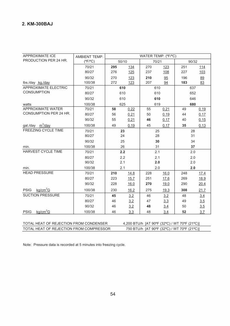
54
2. KM-300BAJ
PERFORMANCE DATA ISSUED:06/02/2017ITEM: HOSHIZAKI CRESCENT CUBERMODEL: KM-300BAJ
70/21 295 134 270 123 251 11480/27 276 125 237 108 227 10390/32 270 123 210 95 196 89
lbs./day kg./day 100/38 272 123 207 94 183 8370/2180/2790/32
watts 100/3870/21 58 0.22 55 0.21 49 0.1980/27 56 0.21 50 0.19 44 0.1790/32 55 0.21 46 0.17 40 0.15
gal./day m3/day 100/38 49 0.19 45 0.17 35 0.1370/2180/2790/32
min. 100/3870/2180/2790/32
min. 100/3870/21 210 14.8 228 16.0 248 17.480/27 223 15.7 251 17.6 269 18.990/32 228 16.0 270 19.0 290 20.4
PSIG kg/cm2G 100/38 230 16.2 275 19.3 308 21.770/21 45 3.2 46 3.2 48 3.480/27 46 3.2 47 3.3 49 3.590/32 46 3.2 48 3.4 50 3.5
PSIG kg/cm2G 100/38 46 3.3 48 3.4 52 3.7
Note: Pressure data is recorded at 5 minutes into freezing cycle.
We reserve the right to make changes in specifications and design without prior notice.
TOTAL HEAT OF REJECTION FROM CONDENSER 4,200 BTU/h [AT 90ºF (32ºC) / WT 70ºF (21ºC)]TOTAL HEAT OF REJECTION FROM COMPRESSOR 750 BTU/h [AT 90ºF (32ºC) / WT 70ºF (21ºC)]
2.1 2.0
APPROVED CHECKED WRITTEN
K.Yamaoka2/Jun/2015
312526
30
2.0
SUCTION PRESSURE
HARVEST CYCLE TIME
HEAD PRESSURE
2.02.0
28313437
637652646680625
610610610619
610610610
23
APPROXIMATE ICEPRODUCTION PER 24 HR.
APPROXIMATE ELECTRICCONSUMPTION
APPROXIMATE WATERCONSUMPTION PER 24 HR.
FREEZING CYCLE TIME
WATER TEMP. (ºF/ºC)AMBIENT TEMP.(ºF/ºC) 50/10 70/21 90/32
242528
2.0
2.2
2.1
2.12.12.0
2.2
\\Hzassv01\manual_data\海外【村瀬】\データ\Icemaker\KM\KM\原稿\KM-230,300B_J\201706\300BAJ SPEC & PERF.xls
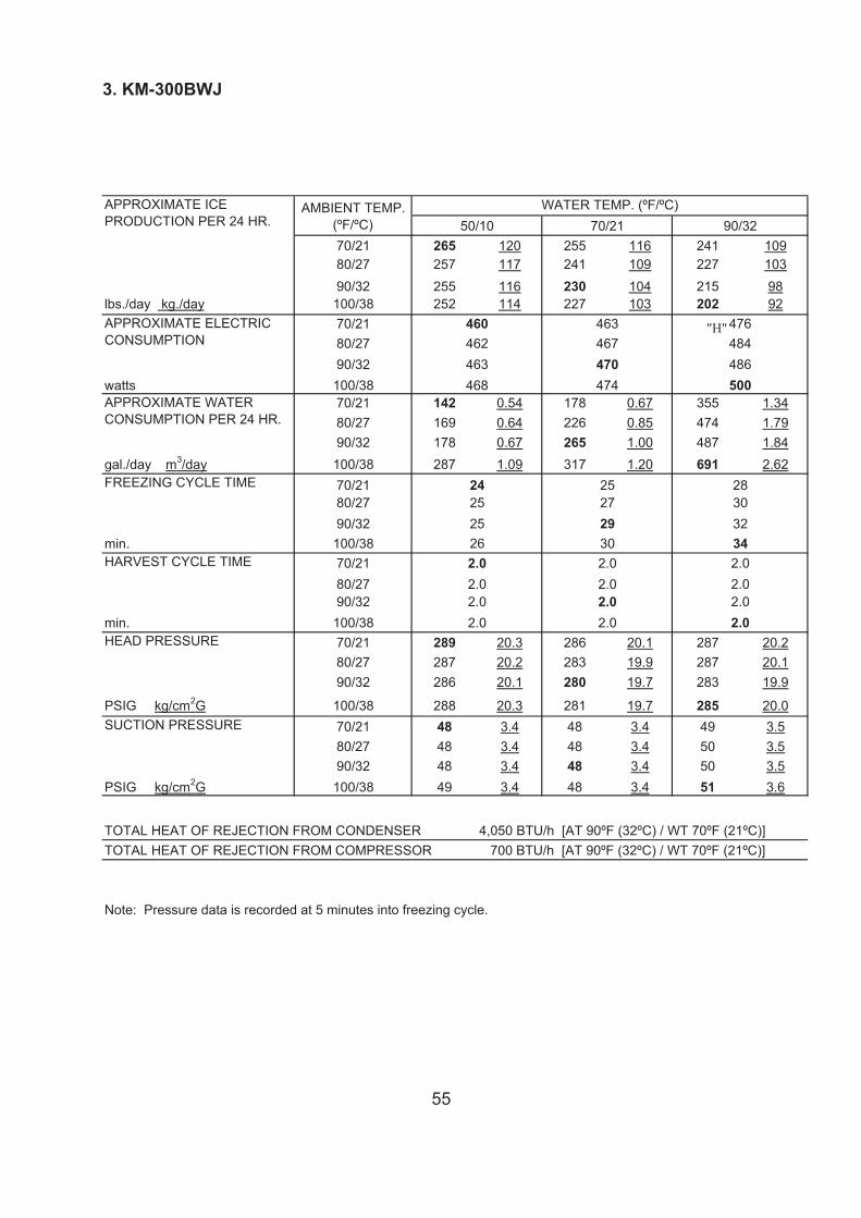
55
PERFORMANCE DATA ISSUED:06/02/2017ITEM: HOSHIZAKI CRESCENT CUBERMODEL: KM-300BWJ
70/21 265 120 255 116 241 10980/27 257 117 241 109 227 10390/32 255 116 230 104 215 98
lbs./day kg./day 100/38 252 114 227 103 202 9270/2180/2790/32
watts 100/3870/21 142 0.54 178 0.67 355 1.3480/27 169 0.64 226 0.85 474 1.7990/32 178 0.67 265 1.00 487 1.84
gal./day m3/day 100/38 287 1.09 317 1.20 691 2.6270/2180/2790/32
min. 100/3870/2180/2790/32
min. 100/3870/21 289 20.3 286 20.1 287 20.280/27 287 20.2 283 19.9 287 20.190/32 286 20.1 280 19.7 283 19.9
PSIG kg/cm2G 100/38 288 20.3 281 19.7 285 20.070/21 48 3.4 48 3.4 49 3.580/27 48 3.4 48 3.4 50 3.590/32 48 3.4 48 3.4 50 3.5
PSIG kg/cm2G 100/38 49 3.4 48 3.4 51 3.6
Note: Pressure data is recorded at 5 minutes into freezing cycle.
We reserve the right to make changes in specifications and design without prior notice.
252527
2.0
2.0
2.0
2.02.02.0
2.0
24
APPROXIMATE ICEPRODUCTION PER 24 HR.
APPROXIMATE ELECTRICCONSUMPTION
APPROXIMATE WATERCONSUMPTION PER 24 HR.
FREEZING CYCLE TIME
WATER TEMP. (ºF/ºC)AMBIENT TEMP.(ºF/ºC) 50/10 70/21 90/32
468
463467470474
460462463
28303234
476484486500
302526
29
2.0
SUCTION PRESSURE
HARVEST CYCLE TIME
HEAD PRESSURE
2.02.0
2.0 2.0
APPROVED CHECKED WRITTEN
K.Yamaoka2/Jun/2015
TOTAL HEAT OF REJECTION FROM CONDENSER 4,050 BTU/h [AT 90ºF (32ºC) / WT 70ºF (21ºC)]TOTAL HEAT OF REJECTION FROM COMPRESSOR 700 BTU/h [AT 90ºF (32ºC) / WT 70ºF (21ºC)]
\\Hzassv01\manual_data\海外【村瀬】\データ\Icemaker\KM\KM\原稿\KM-230,300B_J\201706\300BWJ SPEC & PERF.xls
3. KM-300BWJ
"H"
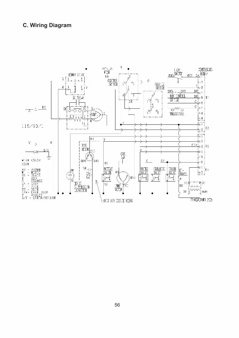
56
C. Wiring Diagram