Service Manual - Alpine Home Air Products and 24 Service... · 2016-08-11 · • Improper...
44
Service Manual Compact Programmable CP-14-18-24-ServMan (04-09) Models 2009 2008
Transcript of Service Manual - Alpine Home Air Products and 24 Service... · 2016-08-11 · • Improper...
Service Manual
Compact Programmable
CP-14-18-24-ServMan (04-09)
Models20092008
FRIEDRICH AIR CONDITIONING CO. Post Office Box 1540 · San Antonio, Texas 78295-1540 4200 N. Pan Am Expressway · San Antonio, Texas 78218-5212 (210) 357-4400 · FAX (210) 357-4490 www.friedrich.com
Printed in the U.S.A.
TECHNICAL SUPPORT CONTACT INFORMATION
1
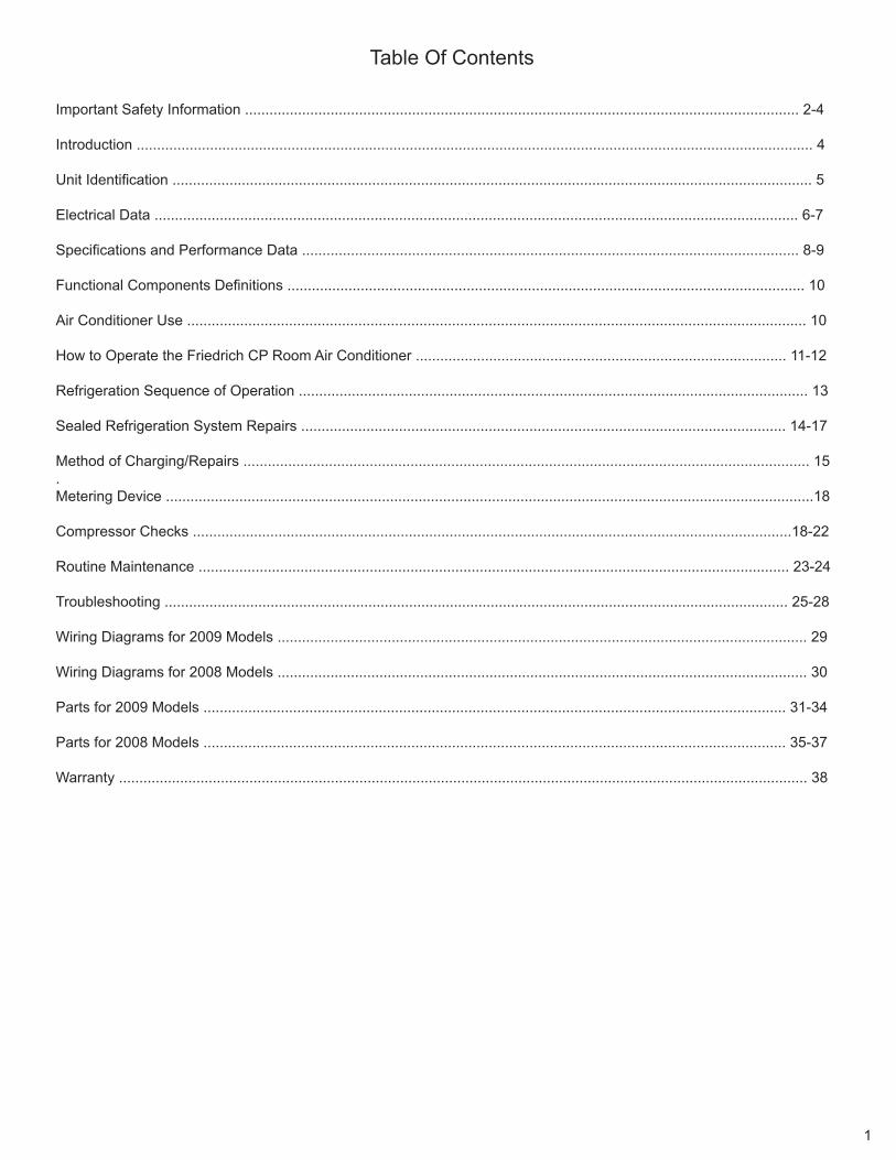
Table Of Contents Important Safety Information ........................................................................................................................................ 2-4
Introduction ...................................................................................................................................................................... 4
Unit Identification ............................................................................................................................................................. 5
Electrical Data .............................................................................................................................................................. 6-7
Specifications and Performance Data .......................................................................................................................... 8-9
Functional Components Definitions ............................................................................................................................... 10
Air Conditioner Use ........................................................................................................................................................ 10
How to Operate the Friedrich CP Room Air Conditioner ........................................................................................... 11-12
Refrigeration Sequence of Operation ............................................................................................................................. 13
Sealed Refrigeration System Repairs ....................................................................................................................... 14-17
Method of Charging/Repairs ........................................................................................................................................... 15 .Metering Device ...............................................................................................................................................................18
Compressor Checks ...................................................................................................................................................18-22
Routine Maintenance ................................................................................................................................................. 23-24
Troubleshooting ......................................................................................................................................................... 25-28
Wiring Diagrams for 2009 Models .................................................................................................................................. 29
Wiring Diagrams for 2008 Models .................................................................................................................................. 30
Parts for 2009 Models ............................................................................................................................................... 31-34
Parts for 2008 Models ............................................................................................................................................... 35-37
Warranty ......................................................................................................................................................................... 38
IMPORTANT SAFETY INFORMATIONThe information contained in this manual is intended for use by a qualified service technician who is familiar with the safety procedures required for installation and repair, and who is equipped with the proper tools and test instruments required to service this product.
Installation or repairs made by unqualified persons can result in subjecting the unqualified person making such repairs as well as the persons being served by the equipment to hazards resulting in injury or electrical shock which can be serious or even fatal.
Safety warnings have been placed throughout this manual to alert you to potential hazards that may be encountered. If you install or perform service on equipment, it is your responsibility to read and obey these warnings to guard against any bodily injury or property damage which may result to you or others.
PERSONAL INJURY OR DEATH HAZARDSELECTRICAL HAZARDS:
Unplug and/or disconnect all electrical power to the unit before performing inspections, •maintenance, or service.
Make sure to follow proper lockout/tag out procedures.•
Always work in the company of a qualified assistant if possible. •
Capacitors, even when disconnected from the electrical power source, retain an electrical charge •potential capable of causing electric shock or electrocution.
Handle, discharge, and test capacitors according to safe, established, standards, and approved •procedures.
Extreme care, proper judgment, and safety procedures must be exercised if it becomes necessary •to test or troubleshoot equipment with the power on to the unit.
Your safety and the safety of others are very important.We have provided many important safety messages in this manual and on your appliance. Always read and obey all safety messages.
All safety messages will tell you what the potential hazard is, tell you how to reduce the chance of injury, and tell you what will happen if the instructions are not followed.
This is a safety Alert symbol.
This symbol alerts you to potential hazards that can kill or hurt you and others.
All safety messages will follow the safety alert symbol with the word “WARNING” or “CAUTION”. These words mean:
You can be killed or seriously injured if you do not follow instructions.
You can receive minor or moderate injury if you do not follow instructions.
A message to alert you of potential property damage will have the word “NOTICE”. Potential property damage can occur if instructions are not followed.
WARNINGCAUTION
NOTICE
2
Do not spray or pour water on the return air grille, discharge air grille, evaporator coil, control panel, •and sleeve on the room side of the air conditioning unit while cleaning.
Electrical component malfunction caused by water could result in electric shock or other electrically •unsafe conditions when the power is restored and the unit is turned on, even after the exterior is dry.
Never operate the A/C unit with wet hands.•
Use air conditioner on a single dedicated circuit within the specified amperage rating. •
Use on a properly grounded outlet only.•
Do not remove ground prong of plug.•
Do not cut or modify the power supply cord.•
Do not use extension cords with the unit.•
Follow all safety precautions and use proper and adequate protective safety aids such as: gloves, •goggles, clothing, adequately insulated tools, and testing equipment etc.
Failure to follow proper safety procedures and/or these warnings can result in serious injury or death. •
REFRIGERATION SYSTEM HAZARDS:
Use approved standard refrigerant recovering procedures and equipment to relieve pressure before •opening system for repair.
Do not allow liquid refrigerant to contact skin. Direct contact with liquid refrigerant can result in minor •to moderate injury.
Be extremely careful when using an oxy-acetylene torch. Direct contact with the torch’s flame or hot •surfaces can cause serious burns.
Make sure to protect personal and surrounding property with fire proof materials.•
Have a fire extinguisher at hand while using a torch.•
Provide adequate ventilation to vent off toxic fumes, and work with a qualified assistant whenever •possible.
Always use a pressure regulator when using dry nitrogen to test the sealed refrigeration system for •leaks, flushing etc.
Make sure to follow all safety precautions and to use proper protective safety aids such as: gloves, •safety glasses, clothing etc.
Failure to follow proper safety procedures and/or these warnings can result in serious injury or death. •
MECHANICAL HAZARDS:
Extreme care, proper judgment and all safety procedures must be followed when testing, •troubleshooting, handling, or working around unit with moving and/or rotating parts.
Be careful when, handling and working around exposed edges and corners of sleeve, chassis, and •other unit components especially the sharp fins of the indoor and outdoor coils.
Use proper and adequate protective aids such as: gloves, clothing, safety glasses etc.•
Failure to follow proper safety procedures and/or these warnings can result in serious injury or death.•
3
4
PROPERTY DAMAGE HAZARDSFIRE DAMAGE HAZARDS:
Read the Installation/Operation Manual for this air conditioning unit prior to operating.•
Use air conditioner on a single dedicated circuit within the specified amperage rating. •
Connect to a properly grounded outlet only.•
Do not remove ground prong of plug.•
Do not cut or modify the power supply cord.•
Do not use extension cords with the unit.•
Failure to follow these instructions can result in fire and minor to serious property damage.•
WATER DAMAGE HAZARDS:
Improper installation maintenance, or servicing of the air conditioner unit, or not following the above •Safety Warnings can result in water damage to personal items or property.
Insure that the unit has a sufficient pitch to the outside to allow water to drain from the unit. •
Do not drill holes in the bottom of the drain pan or the underside of the unit. •
Failure to follow these instructions can result in result in damage to the unit and/or minor to serious •property damage.
INTRODUCTIONThis service manual is designed to be used in conjunction with the installation manuals provided with each unit.
This service manual was written to assist the professional HVAC service technician to quickly and accurately diagnose and repair any malfunctions of this product.
This manual, therefore, will deal with all subjects in a general nature. (i.e. All text will pertain to all models).
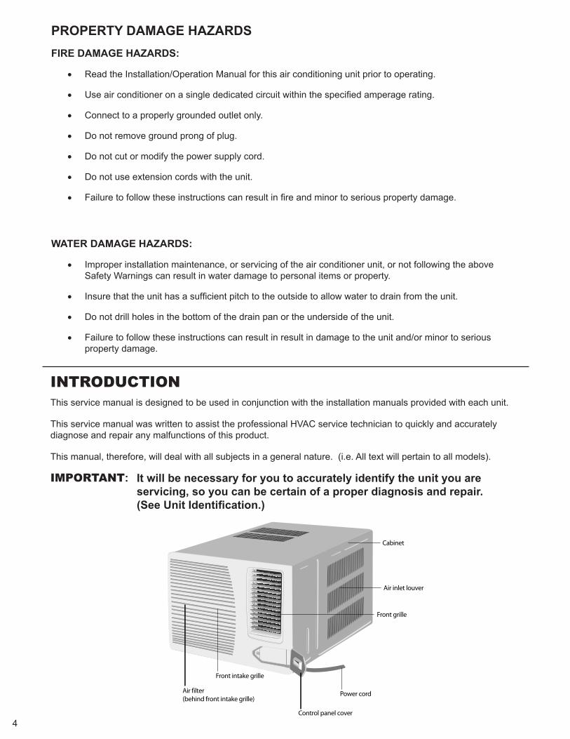
IMPORTANT: It will be necessary for you to accurately identify the unit you are servicing, so you can be certain of a proper diagnosis and repair. (See Unit Identification.)
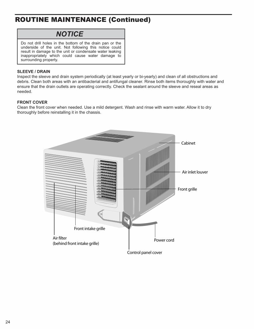
Cabinet
Air inlet louver
Front grille
Power cord
Control panel cover
Front intake grille
Air filter(behind front intake grille)
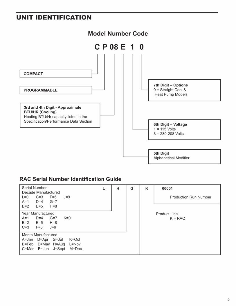
Serial Number Decade Manufactured L=0 C=3 F=6 J=9 A=1 D=4 G=7 B=2 E=5 H=8
L H G K 00001
Production Run Number
Year Manufactured A=1 D=4 G=7 K=0 B=2 E=5 H=8 C=3 F=6 J=9
Product Line K = RAC
Month Manufactured A=Jan D=Apr G=Jul K=Oct B=Feb E=May H=Aug L=Nov C=Mar F=Jun J=Sept M=Dec
3rd and 4th Digit - Approximate BTU/HR (Cooling) Heating BTU/Hr capacity listed in the Specification/Performance Data Section
7th Digit – Options 0 = Straight Cool & Heat Pump Models
6th Digit – Voltage 1 = 115 Volts 3 = 230-208 Volts
5th Digit Alphabetical Modifier
COMPACT
PROGRAMMABLE
Model Number Code C P 08 E 1 0
RAC Serial Number Identification Guide
UNIT IDeNTIfICATION
5
eleCTRICAl DATA
ELECTRIC SHOCK HAZARD
WARNING
Turn off electric power before service or installation.
All electrical connections and wiring MUST be installed by a qualified electrician and conform to the National Electrical Code and all local codes which have jurisdiction.Failure to do so can result in personal injury or death.
Not following the above WARNING could result in fire or electically unsafe conditions which could cause moderate or serious property damage.Read, understand and follow the above warning.
NOTICEFIRE HAZARD
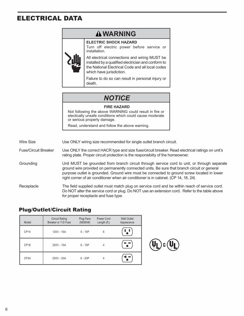
Wire Size Use ONLY wiring size recommended for single outlet branch circuit.
Fuse/Circuit Breaker Use ONLY the correct HACR type and size fuse/circuit breaker. Read electrical ratings on unit’s rating plate. Proper circuit protection is the responsibiity of the homeowner.
Grounding Unit MUST be grounded from branch circuit through service cord to unit, or through separate ground wire provided on permanently connected units. Be sure that branch circuit or general purpose outlet is grounded. Ground wire must be connected to ground screw located in lower right corner of air conditioner when air conditioner is in cabinet. (CP 14, 18, 24)
Receptacle The field supplied outlet must match plug on service cord and be within reach of service cord. Do NOT alter the service cord or plug. Do NOT use an extension cord. Refer to the table above for proper receptacle and fuse type.
Plug/Outlet/Circuit Rating
ModelCircuit Rating
Breaker or T-D FusePlug Face(NEMA#)
Power CordLength (ft.)
Wall OutletAppearance
CP14 125V - 15A 5 - 15P 6
CP18 250V - 15A 6 - 15P 4
CP24 250V - 20A 6 - 20P 4
6
7
ELECTRICAL SHOCK HAZARD
WARNING
Plug into a grounded 3 prong outlet. Do not remove powercord ground prong. Do not use a plug adapter. Do not use an extension cord. Failure to follow these instructions can result in death, fire, or electrical shock.
This air conditioner must be grounded. This air conditioner is equipped with a power supply cord having a grounded 3 prong plug. To minimize possible shock hazard, the cord must be plugged into a mating, grounded 3 prong outlet, grounded in accordance with all local codes and ordinances. If a mating outlet is not available, it is the customer’s responsibility to have a properly grounded 3 prong outlet installed by a qualified electrical component installer. It is the customer’s responsibility:
To contact a qualified electrical installer, and to assure that the electrical installation is adequate and in conformance with National Electrical Code, ANSI/NFPA 70 - latest edition, and all local codes and ordinances.
Copies of the standards listed may be obtained from:
National Fire Protection Association One Batterymarch Park Quincy, MA 02269
Recommended grounding method
To test your power supply cord:
1. Plug power supply cord into a grounded 3 prong outlet.
2. Press RESET.
3. Press TEST (listen for click; Reset button will trip and pop out).
4. Press and release RESET (listen for click; Reset butto will latch and remain in). The power supply cord is ready for operation.
NOTES:
The Reset button must be pushed in for proper operation.
The power supply cord must be replaced if it fails to trip when the test button is pressed or if it fails to reset. Do not use the power supply cord as an off/on switch. The power supply cord is designed as a protective device. A damaged power supply cord must be replaced with a new power supply cord obtained from the product manufacturer and must not be repaired. The power supply cord contains no user serviceable parts. Opening the tamper-resistant case voids all warranty and performance claims.
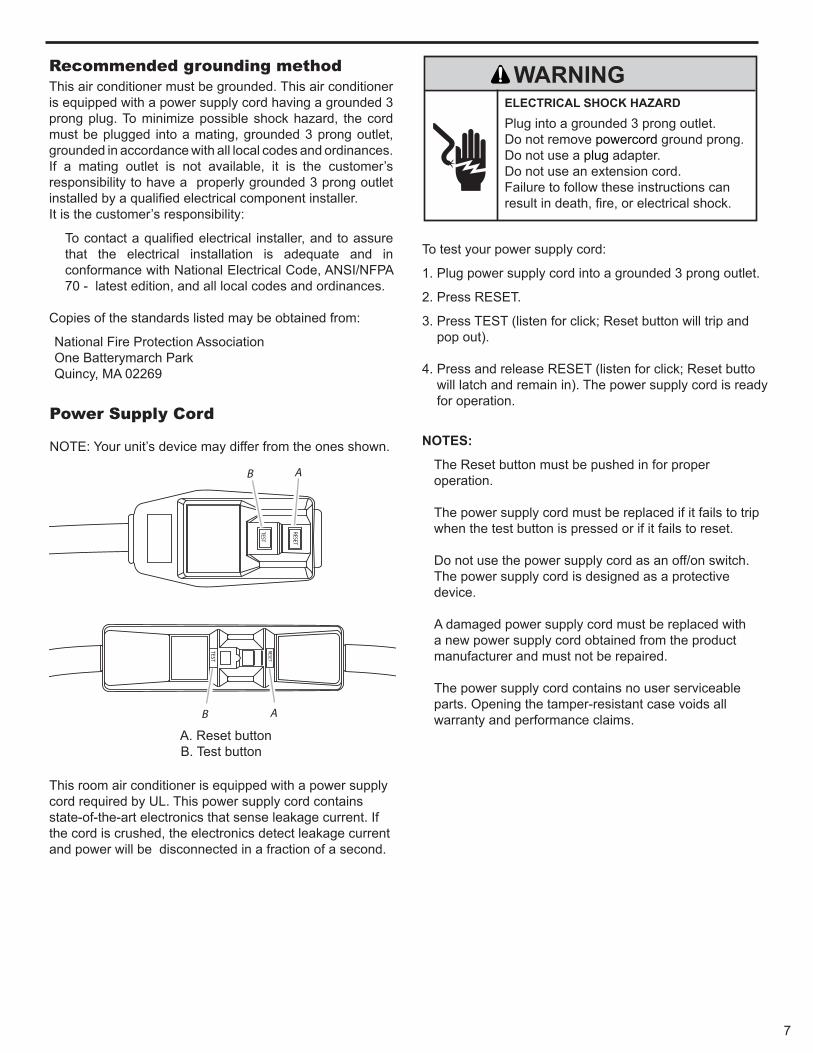
Power Supply Cord NOTE: Your unit’s device may differ from the ones shown.
A. Reset button B. Test button
This room air conditioner is equipped with a power supply cord required by UL. This power supply cord contains state-of-the-art electronics that sense leakage current. If the cord is crushed, the electronics detect leakage current and power will be disconnected in a fraction of a second.
TEST
TEST
RESET
RESET
A
AB
B
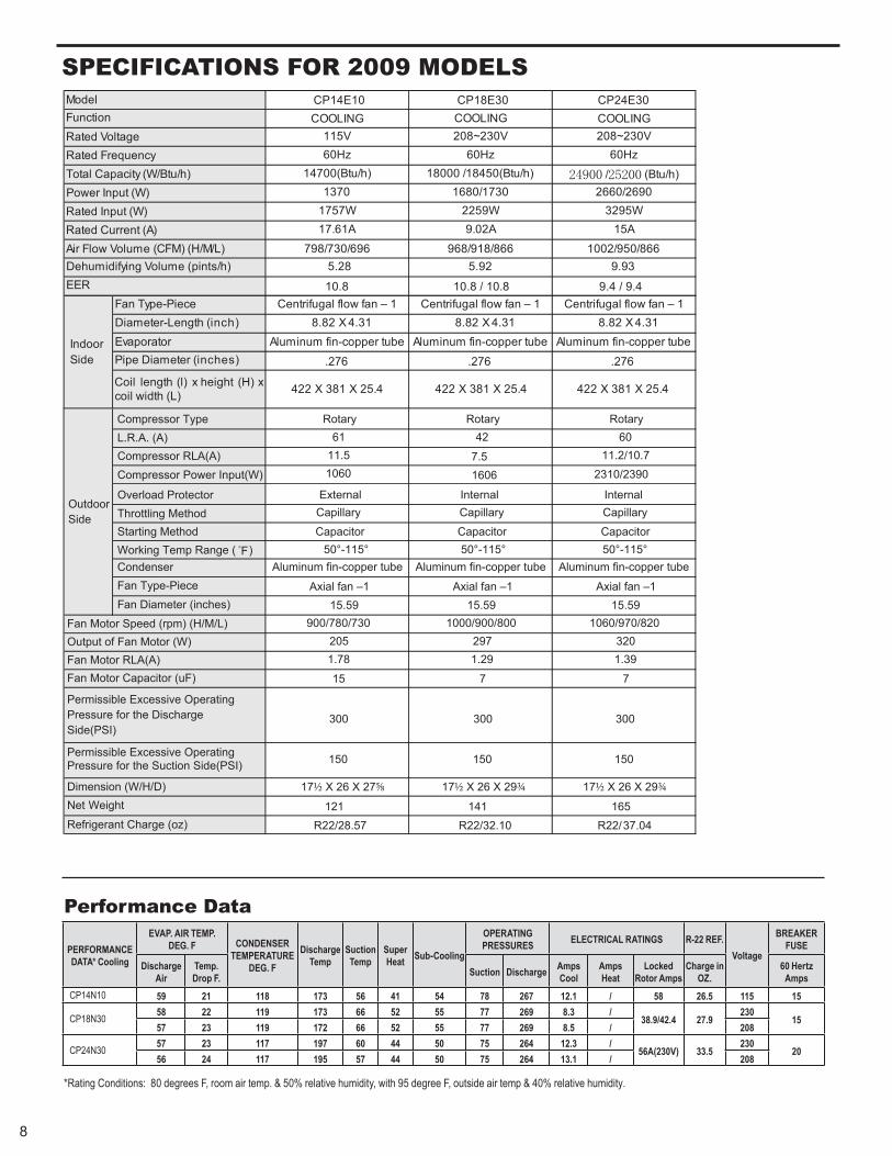
SPeCIfICATIONS fOR 2009 MODelS
8
Performance Data
PERFORMANCE DATA* Cooling
EVAP. AIR TEMP. DEG. F CONDENSER
TEMPERATURE DEG. F
Discharge Temp
Suction Temp
Super Heat Sub-Cooling
OPERATING PRESSURES ELECTRICAL RATINGS R-22 REF.
Voltage
BREAKER FUSE
Discharge Air
Temp. Drop F. Suction Discharge Amps
CoolAmpsHeat
Locked Rotor Amps
Charge in OZ.
60 Hertz Amps
CP14N10 59 21 118 173 56 41 54 78 267 12.1 / 58 26.5 115 15
CP18N30 58 22 119 173 66 52 55 77 269 8.3 /38.9/42.4 27.9
23015
802/5.8 962 775525 66 271 911 32 75
CP24N30 57 23 117 197 60 44 50 75 264 12.3 /56A(230V) 33.5
23020
802/1.31 462 570544 75 591 711 42 65
*Rating Conditions: 80 degrees F, room air temp. & 50% relative humidity, with 95 degree F, outside air temp & 40% relative humidity.
Compressor Type Rotary Rotary RotaryL.R.A. (A) 61 42 60Compressor RLA(A) 11.5 11.2/10.7
Compressor Power Input(W) 1060 2310/2390
Overload Protector InternalExternal InternalThrottling Method Capillary Capillary Capillary
Starting Method Capacitor Capacitor CapacitorWorking Temp Range ( F) 50°-115° 50°-115° 50°-115°Condenser Aluminum fin-copper tube Aluminum fin-copper tube Aluminum fin-copper tubeFan Type-Piece Axial fan –1 Axial fan –1 Axial fan –1Fan Diameter (inches) 15.59 15.59 15.59
900/780/730 1000/900/800 1060/970/820205 297 3201.78 1.29 1.39
15 7 7
300 300 300
150 150 150
17½ X 26 X 27⅝ 17½ X 26 X 29¾ 17½ X 26 X 29¾121 141 165
R22/28.57 R22/32.10 R22/37.04
OutdoorSide
Fan Motor Speed (rpm) (H/M/L)Output of Fan Motor (W)Fan Motor RLA(A)Fan Motor Capacitor (uF)
Net Weight
Refrigerant Charge (oz)
Permissible Excessive OperatingPressure for the DischargeSide(PSI)
Permissible Excessive OperatingPressure for the Suction Side(PSI)
Dimension (W/H/D)
7.51606
CP14E10 CP18E30 CP24E30COOLING COOLING COOLING
115V 208~230V 208~230V60Hz 60Hz 60Hz
14700(Btu/h) 18000 /18450(Btu/h) / (Btu/h)1370 1680/1730 2660/2690
1757W 2259W 3295W17.61A 9.02A 15A
798/730/696 968/918/866 1002/950/8665.28 5.92 9.93
10.8 10.8 / 10.8 9.4 / 9.4Fan Type-Piece Centrifugal flow fan – 1 Centrifugal flow fan – 1 Centrifugal flow fan – 1Diameter-Length (inch) 8.82 X 4.31 8.82 X 4.31 8.82 X 4.31Evaporator Aluminum fin-copper tube Aluminum fin-copper tube Aluminum fin-copper tubePipe Diameter (inches) .276 .276 .276
Coil length (l) x height (H) xcoil width (L) 422 X 381 X 25.4 422 X 381 X 25.4 422 X 381 X 25.4
ModelFunctionRated Voltage
Rated Input (W)Rated Current (A)Air Flow Volume (CFM) (H/M/L)
Rated FrequencyTotal Capacity (W/Btu/h)Power Input (W)
IndoorSide
Dehumidifying Volume (pints/h)EER
PERFORMANCE DATA* Cooling
EVAP. AIR TEMP. DEG. F CONDENSER
TEMPERATURE DEG. F
Discharge Temp
Suction Temp
Super Heat Sub-Cooling
OPERATING PRESSURES ELECTRICAL RATINGS R-22 REF.
Voltage
BREAKER FUSE
Discharge Air
Temp. Drop F. Suction Discharge Amps
CoolAmpsHeat
Locked Rotor Amps
Charge in OZ.
60 Hertz Amps
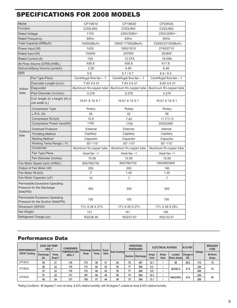
CP14N10 59 21 118 173 56 41 54 78 267 12.1 / 58 26.5 115 15
CP18N30 58 22 119 173 66 52 55 77 269 8.3 /38.9/42.4 27.9
23015
802/5.8 962 775525 66 271 911 32 75
CP24N30 57 23 117 197 60 44 50 75 264 12.3 /56A(230V) 33.5
23020
802/1.31 462 570544 75 591 711 42 65
*Rating Conditions: 80 degrees F, room air temp. & 50% relative humidity, with 95 degree F, outside air temp & 40% relative humidity.
Compressor Type Rotary Rotary RotaryL.R.A. (A) 58 42 56Compressor RLA(A) 10.9 11.7/11.0Compressor Power Input(W) 1182 2425/2480
Overload Protector ExternalExternal InternalThrottling Method Capillary Capillary Capillary
Starting Method Capacitor Capacitor CapacitorWorking Temp Range ( F) 50°-115° 50°-115° 50°-115°Condenser Aluminum fin-copper tube Aluminum fin-copper tube Aluminum fin-copper tubeFan Type-Piece Axial fan –1 Axial fan –1 Axial fan –1Fan Diameter (inches) 15.59 15.59 15.59
900/780/730 900/780/730 1000/900/800
200 200 1903 1.45 1.35
15 7 7
300 300 300
150 150 150
17½ X 26 X 27⅝ 17½ X 26 X 27⅝ 17½ X 26 X 29¾121 141 165
R22/26.46 R22/27.87 R22/33.51
OutdoorSide
Fan Motor Speed (rpm) (H/M/L)Output of Fan Motor (W)Fan Motor RLA(A)Fan Motor Capacitor (uF)
Net Weight
Refrigerant Charge (oz)
Permissible Excessive OperatingPressure for the DischargeSide(PSI)
Permissible Excessive OperatingPressure for the Suction Side(PSI)
Dimension (W/H/D)
7.451700
CP14N10 CP18N30 CP24N30COOLING COOLING COOLING
115V 230V/208V~ 230V/208V~60Hz 60Hz 60Hz
14000(Btu/h) 18000 /17600(Btu/h) 23500/23100(Btu/h)1430 1850/1810 2740/2710
1540W 2478W 3538W15A 12.57A 18.09A458.8 458.8 617.63.38 4.65 8.469.8 9.7 / 9.7 8.6 / 8.5
Fan Type-Piece Centrifugal flow fan – 1 Centrifugal flow fan – 1 Centrifugal flow fan – 1
Diameter-Length (inch) 7.93 X 4.31 7.93 X 4.31 8.82 X 4.31Evaporator Aluminum fin-copper tube Aluminum fin-copper tube Aluminum fin-copper tube
Pipe Diameter (inches) 0.276 0.276 0.276
Coil length (l) x height (H) xcoil width (L)
16.61 X 15 X 1 16.61 X 15 X 1 16.61 X 15 X 1
ModelFunction
Rated Voltage
Rated Input (W)Rated Current (A)Air Flow Volume (CFM) (H/M/L)
Rated FrequencyTotal Capacity (W/Btu/h)
Power Input (W)
IndoorSide
Dehumidifying Volume (pints/h)EER
9
SPeCIfICATIONS fOR 2008 MODelS
Performance Data
10
COMPONeNT DefINITIONSA. Mechanical components
B. Electrical components
C. Hermetic components
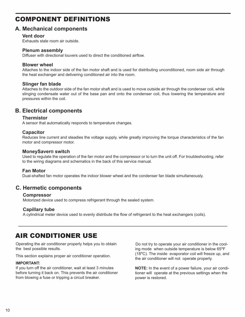
Vent door Exhausts stale room air outside. Plenum assembly Diffuser with directional louvers used to direct the conditioned airflow.
Blower wheelAttaches to the indoor side of the fan motor shaft and is used for distributing unconditioned, room side air through the heat exchanger and delivering conditioned air into the room.
Slinger fan bladeAttaches to the outdoor side of the fan motor shaft and is used to move outside air through the condenser coil, while slinging condensate water out of the base pan and onto the condenser coil, thus lowering the temperature and pressures within the coil.
ThermistorA sensor that automatically responds to temperature changes.
CapacitorReduces line current and steadies the voltage supply, while greatly improving the torque characteristics of the fan motor and compressor motor.
MoneySaver® switchUsed to regulate the operation of the fan motor and the compressor or to turn the unit off. For troubleshooting, refer to the wiring diagrams and schematics in the back of this service manual.
Fan MotorDual-shafted fan motor operates the indoor blower wheel and the condenser fan blade simultaneously.
CompressorMotorized device used to compress refrigerant through the sealed system.
Capillary tubeA cylindrical meter device used to evenly distribute the flow of refrigerant to the heat exchangers (coils).
AIR CONDITIONeR USe Operating the air conditioner properly helps you to obtain the best possible results.
This section explains proper air conditioner operation.
IMPORTANT: If you turn off the air conditioner, wait at least 3 minutes before turning it back on. This prevents the air conditioner from blowing a fuse or tripping a circuit breaker.
Do not try to operate your air conditioner in the cool-ing mode when outside temperature is below 65°F (18°C). The inside evaporator coil will freeze up, and the air conditioner will not operate properly.
NOTE: In the event of a power failure, your air condi-tioner will operate at the previous settings when the power is restored.
11
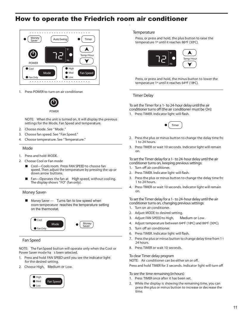
1. Press POWER to turn on air conditioner.
NOTE: When the unit is turned on, it will display the previoussettings for the Mode, Fan Speed and temperature.
2. Choose mode. See “Mode.”3. Choose fan speed. See “Fan Speed.”4. Choose temperature. See “Temperature.”
Mode
1. Press and hold MODE.2.
Cool—Cools room. Press FAN SPEED to choose fan speed. Then adjust the temperature by pressing the up ordown arrow buttons.
Fan—Operates the fan at High speed, without cool ing.The display shows “FO” (fan only).
Fan Speed
NOTE: The Fan Speed button will operate only when the Cool orPower Saver mode ha s been selected.1. Press and hold FAN SPEED until you see the indicator light
for the desired setting.2. Choose High, Medium or Low.
TemperaturePress, or press and hold, the plus button to raise thetemperature 1º until it reaches 86ºF (30ºC).
Press, or press and hold, the minus button to lower thetemperature 1º until it reaches 64ºF (18ºC).
Timer Delay
To set the Timer for a 1- to 24-hour delay until the airconditioner turns o� (the air conditioner must be On):1. Press TIMER. Indicator light will �ash.
2. Press the plus or minus button to change the delay time from1 to 24 hours.
3. Press TIMER or wait 10 seconds. Indicator light will remainon.
To set the Timer delay for a 1- to 24-hour delay until the airconditioner turns on, keeping previous settings:1. Turn o� air conditioner.2. Press TIMER. Indicator light will �ash.3. Press the plus or minus button to change the delay time from
1 to 24 hours.4. Press TIMER or wait 10 seconds. Indicator light will remain
on.
To set the Timer delay for a 1- to 24-hour delay until the airconditioner turns on, changing previous settings:1. Turn on air conditioner.2. Adjust MODE to desired setting.3. Adjust FAN SPEED to High, Medium or Low.4. Adjust temperature between 64ºF (18ºC) and 86ºF (30ºC).5. Turn o� air conditioner.6. Press TIMER. Indicator light will �ash.7. Press the plus or minus button to change delay time from 1 to
24 hours.8. Press TIMER or wait 10 seconds.
To clear Timer delay programNOTE: Air conditioner can be either on or o�.Press and hold TIMER for 3 seconds. Indicator light will turn o�.
To see the time remaining (in hours)1. Press TIMER once after it has been set.2. While the display is showing the remaining time, you can
press the plus or minus button to increase or decrease thetime.
POWER
Temp/Hour
Timer
Fan SpeedFan Only
Cool
MoneySaver®
High
Med
Low
0F
Mode
Hr.
Auto Swing
Temp/Hour
0F
Hr.
Timer
Money Saver — Turns fan to low speed whenroom temperature reaches the temperature setting on the thermostat.
Fan Only
Cool
Mode MoneySaver®
Fan SpeedHigh
Med
Low
POWER
Money Saver®
Choose Cool or Fan mode
How to operate the friedrich room air conditioner
12
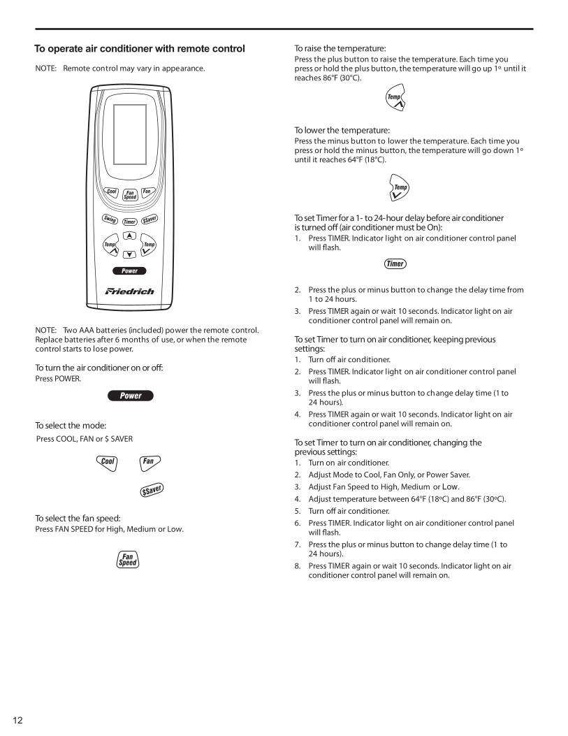
To operate air conditioner with remote control
NOTE: Remote control may vary in appearance.
NOTE: Two AAA batteries (included) power the remote control.Replace batteries after 6 months of use, or when the remotecontrol starts to lose power.
To turn the air conditioner on or o�:Press POWER.
To select the mode:
To select the fan speed:Press FAN SPEED for High, Medium or Low.
To raise the temperature:Press the plus button to raise the temperature. Each time youpress or hold the plus button, the temperature will go up 1º until itreaches 86°F (30°C).
To lower the temperature:Press the minus button to lower the temperature. Each time youpress or hold the minus button, the temperature will go down 1ºuntil it reaches 64°F (18°C).
To set Timer for a 1- to 24-hour delay before air conditioneris turned o� (air conditioner must be On):1. Press TIMER. Indicator light on air conditioner control panel
will �ash.
2. Press the plus or minus button to change the delay time from1 to 24 hours.
3. Press TIMER again or wait 10 seconds. Indicator light on air conditioner control panel will remain on.
To set Timer to turn on air conditioner, keeping previoussettings:1. Turn o� air conditioner.2. Press TIMER. Indicator light on air conditioner control panel
will �ash.3. Press the plus or minus button to change delay time (1 to
24 hours).4. Press TIMER again or wait 10 seconds. Indicator light on air
conditioner control panel will remain on.
To set Timer to turn on air conditioner, changing theprevious settings:1. Turn on air conditioner.2. Adjust Mode to Cool, Fan Only, or Power Saver.3. Adjust Fan Speed to High, Medium or Low.4. Adjust temperature between 64°F (18ºC) and 86°F (30ºC).5. Turn o� air conditioner.6. Press TIMER. Indicator light on air conditioner control panel
will �ash.7. Press the plus or minus button to change delay time (1 to
24 hours).8. Press TIMER again or wait 10 seconds. Indicator light on air
conditioner control panel will remain on.
Press COOL, FAN or $ SAVER
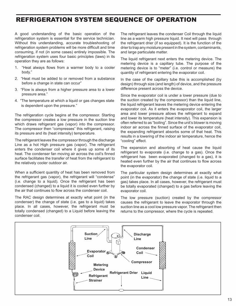
Suction Line
Evaporator Coil
Metering Device
Refrigerant Strainer
Discharge Line
Condenser Coil
Compressor
Refrigerant Drier Liquid Line
A good understanding of the basic operation of the refrigeration system is essential for the service technician. Without this understanding, accurate troubleshooting of refrigeration system problems will be more difficult and time consuming, if not (in some cases) entirely impossible. The refrigeration system uses four basic principles (laws) in its operation they are as follows:
1. “Heat always flows from a warmer body to a cooler body.”
2. “Heat must be added to or removed from a substance before a change in state can occur”
3. “Flow is always from a higher pressure area to a lower pressure area.”
4. “The temperature at which a liquid or gas changes state is dependent upon the pressure.” The refrigeration cycle begins at the compressor. Starting the compressor creates a low pressure in the suction line which draws refrigerant gas (vapor) into the compressor. The compressor then “compresses” this refrigerant, raising its pressure and its (heat intensity) temperature.
The refrigerant leaves the compressor through the discharge Line as a hot High pressure gas (vapor). The refrigerant enters the condenser coil where it gives up some of its heat. The condenser fan moving air across the coil’s finned surface facilitates the transfer of heat from the refrigerant to the relatively cooler outdoor air. When a sufficient quantity of heat has been removed from the refrigerant gas (vapor), the refrigerant will “condense” (i.e. change to a liquid). Once the refrigerant has been condensed (changed) to a liquid it is cooled even further by the air that continues to flow across the condenser coil.
The RAC design determines at exactly what point (in the condenser) the change of state (i.e. gas to a liquid) takes place. In all cases, however, the refrigerant must be totally condensed (changed) to a Liquid before leaving the condenser coil.
The refrigerant leaves the condenser Coil through the liquid line as a warm high pressure liquid. It next will pass through the refrigerant drier (if so equipped). It is the function of the drier to trap any moisture present in the system, contaminants, and large particulate matter.
The liquid refrigerant next enters the metering device. The metering device is a capillary tube. The purpose of the metering device is to “meter” (i.e. control or measure) the quantity of refrigerant entering the evaporator coil.
In the case of the capillary tube this is accomplished (by design) through size (and length) of device, and the pressure difference present across the device.
Since the evaporator coil is under a lower pressure (due to the suction created by the compressor) than the liquid line, the liquid refrigerant leaves the metering device entering the evaporator coil. As it enters the evaporator coil, the larger area and lower pressure allows the refrigerant to expand and lower its temperature (heat intensity). This expansion is often referred to as “boiling”. Since the unit’s blower is moving indoor air across the finned surface of the evaporator coil, the expanding refrigerant absorbs some of that heat. This results in a lowering of the indoor air temperature, hence the “cooling” effect.
The expansion and absorbing of heat cause the liquid refrigerant to evaporate (i.e. change to a gas). Once the refrigerant has been evaporated (changed to a gas), it is heated even further by the air that continues to flow across the evaporator coil.
The particular system design determines at exactly what point (in the evaporator) the change of state (i.e. liquid to a gas) takes place. In all cases, however, the refrigerant must be totally evaporated (changed) to a gas before leaving the evaporator coil.
The low pressure (suction) created by the compressor causes the refrigerant to leave the evaporator through the suction line as a cool low pressure vapor. The refrigerant then returns to the compressor, where the cycle is repeated.
RefRIGeRATION SYSTeM SeQUeNCe Of OPeRATION
13
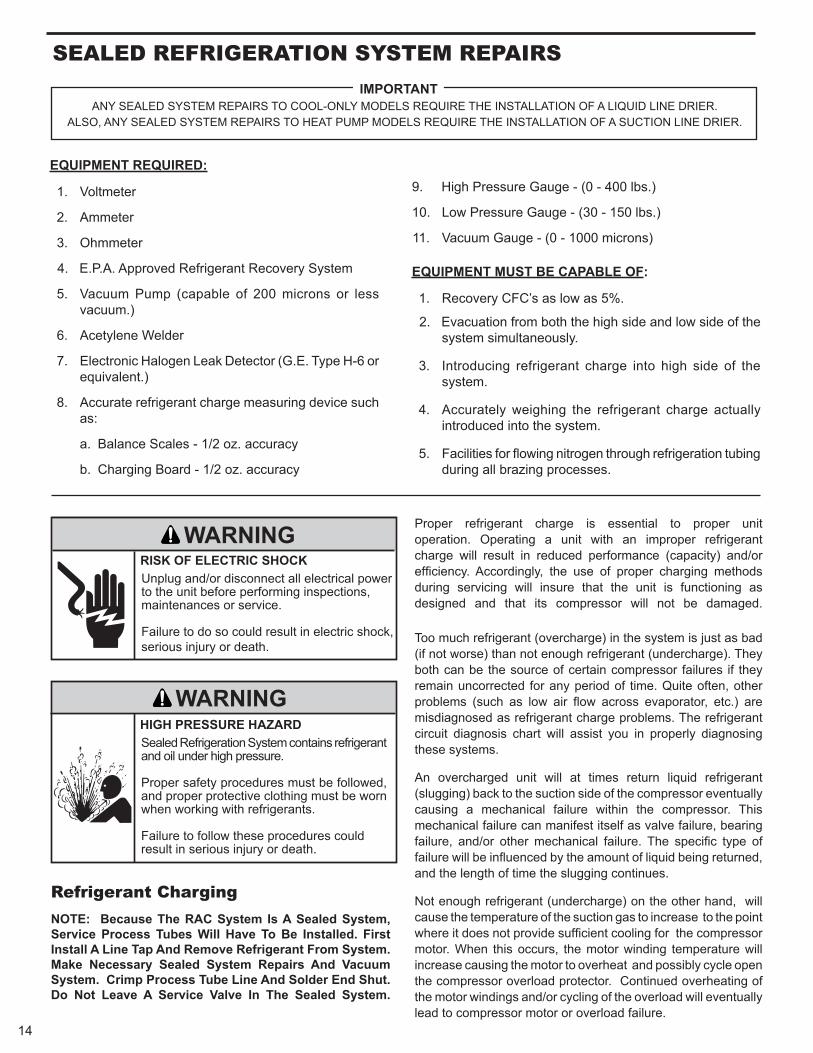
Refrigerant Charging NOTE: Because The RAC System Is A Sealed System, Service Process Tubes Will Have To Be Installed. First Install A Line Tap And Remove Refrigerant From System. Make Necessary Sealed System Repairs And Vacuum System. Crimp Process Tube Line And Solder End Shut. Do Not Leave A Service Valve In The Sealed System.
Proper refrigerant charge is essential to proper unit operation. Operating a unit with an improper refrigerant charge will result in reduced performance (capacity) and/or efficiency. Accordingly, the use of proper charging methods during servicing will insure that the unit is functioning as designed and that its compressor will not be damaged.
Too much refrigerant (overcharge) in the system is just as bad (if not worse) than not enough refrigerant (undercharge). They both can be the source of certain compressor failures if they remain uncorrected for any period of time. Quite often, other problems (such as low air flow across evaporator, etc.) are misdiagnosed as refrigerant charge problems. The refrigerant circuit diagnosis chart will assist you in properly diagnosing these systems.
An overcharged unit will at times return liquid refrigerant (slugging) back to the suction side of the compressor eventually causing a mechanical failure within the compressor. This mechanical failure can manifest itself as valve failure, bearing failure, and/or other mechanical failure. The specific type of failure will be influenced by the amount of liquid being returned, and the length of time the slugging continues.
Not enough refrigerant (undercharge) on the other hand, will cause the temperature of the suction gas to increase to the point where it does not provide sufficient cooling for the compressor motor. When this occurs, the motor winding temperature will increase causing the motor to overheat and possibly cycle open the compressor overload protector. Continued overheating of the motor windings and/or cycling of the overload will eventually lead to compressor motor or overload failure.
Unplug and/or disconnect all electrical power to the unit before performing inspections, maintenances or service. Failure to do so could result in electric shock, serious injury or death.
Sealed Refrigeration System contains refrigerant and oil under high pressure.
Proper safety procedures must be followed, and proper protective clothing must be worn when working with refrigerants.
Failure to follow these procedures could result in serious injury or death.
WARNING
WARNING
RISK OF ELECTRIC SHOCK
HIGH PRESSURE HAZARD
SeAleD RefRIGeRATION SYSTeM RePAIRS
ANY SEALED SYSTEM REPAIRS TO COOL-ONLY MODELS REQUIRE THE INSTALLATION OF A LIQUID LINE DRIER. ALSO, ANY SEALED SYSTEM REPAIRS TO HEAT PUMP MODELS REQUIRE THE INSTALLATION OF A SUCTION LINE DRIER.
IMPORTANT
EQUIPMENT REQUIRED:
1. Voltmeter
2. Ammeter
3. Ohmmeter
4. E.P.A. Approved Refrigerant Recovery System
5. Vacuum Pump (capable of 200 microns or less vacuum.)
6. Acetylene Welder
7. Electronic Halogen Leak Detector (G.E. Type H-6 or equivalent.)
8. Accurate refrigerant charge measuring device such as:
a. Balance Scales - 1/2 oz. accuracy
b. Charging Board - 1/2 oz. accuracy
9. High Pressure Gauge - (0 - 400 lbs.)
10. Low Pressure Gauge - (30 - 150 lbs.)
11. Vacuum Gauge - (0 - 1000 microns)
EQUIPMENT MUST BE CAPABLE OF:
1. Recovery CFC’s as low as 5%.
2. Evacuation from both the high side and low side of the system simultaneously.
3. Introducing refrigerant charge into high side of the system.
4. Accurately weighing the refrigerant charge actually introduced into the system.
5. Facilities for flowing nitrogen through refrigeration tubing during all brazing processes.
14
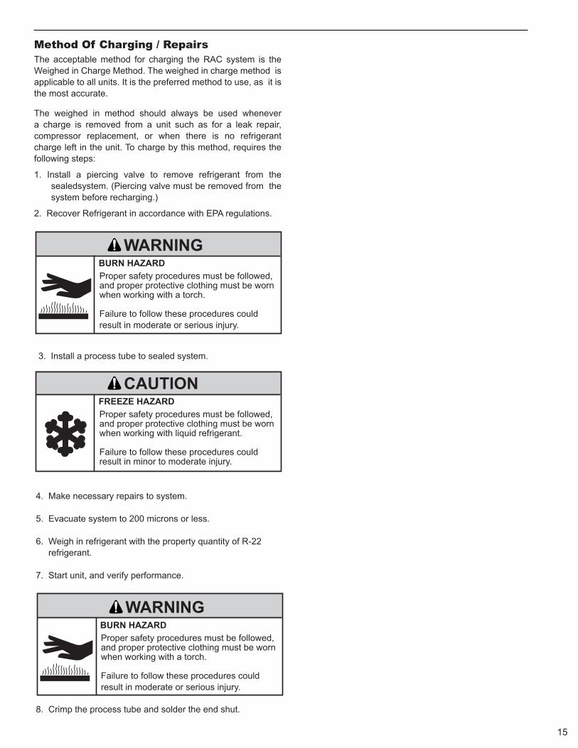
3. Install a process tube to sealed system.
4. Make necessary repairs to system. 5. Evacuate system to 200 microns or less. 6. Weigh in refrigerant with the property quantity of R-22 refrigerant. 7. Start unit, and verify performance.
8. Crimp the process tube and solder the end shut.
Proper safety procedures must be followed, and proper protective clothing must be worn when working with a torch.
Failure to follow these procedures could result in moderate or serious injury.
Proper safety procedures must be followed, and proper protective clothing must be worn when working with liquid refrigerant.
Failure to follow these procedures could result in minor to moderate injury.
WARNING
CAUTION
BURN HAZARD
FREEZE HAZARD
Proper safety procedures must be followed, and proper protective clothing must be worn when working with a torch.
Failure to follow these procedures could result in moderate or serious injury.
WARNINGBURN HAZARD
Method Of Charging / Repairs The acceptable method for charging the RAC system is the Weighed in Charge Method. The weighed in charge method is applicable to all units. It is the preferred method to use, as it is the most accurate.
The weighed in method should always be used whenever a charge is removed from a unit such as for a leak repair, compressor replacement, or when there is no refrigerant charge left in the unit. To charge by this method, requires the following steps:
1. Install a piercing valve to remove refrigerant from the sealedsystem. (Piercing valve must be removed from the system before recharging.)
2. Recover Refrigerant in accordance with EPA regulations.
15

Undercharged Refrigerant Systems An undercharged system will result in poor performance (low pressures, etc.) in both the heating and cooling cycle.
Whenever you service a unit with an undercharge of refrigerant, always suspect a leak. The leak must be repaired before charging the unit.
To check for an undercharged system, turn the unit on, allow the compressor to run long enough to establish working pressures in the system (15 to 20 minutes).
During the cooling cycle you can listen carefully at the exit of the metering device into the evaporator; an intermittent hissing and gurgling sound indicates a low refrigerant charge. Intermittent frosting and thawing of the evaporator is another indication of a low charge, however, frosting and thawing can also be caused by insufficient air over the evaporator.
Checks for an undercharged system can be made at the compressor. If the compressor seems quieter than normal, it is an indication of a low refrigerant charge.
Overcharged Refrigerant Systems
A check of the amperage drawn by the compressor motor should show a lower reading. (Check the Unit Specification.) After the unit has run 10 to 15 minutes, check the gauge pressures. Gauges connected to system with an undercharge will have low head pressures and substantially low suction pressures.
of the evaporator will not be encountered because the refrigerant will boil later if at all. Gauges connected to system will usually have higher head pressure (depending upon amount of over charge). Suction pressure should be slightly higher.
Compressor amps will be near normal or higher. Noncondensables can also cause these symptoms. To confirm, remove some of the charge, if conditions improve, system may be overcharged. If conditions don’t improve, Noncondensables are indicated.
Whenever an overcharged system is indicated, always make sure that the problem is not caused by air flow problems. Improper air flow over the evaporator coil may indicate some of the same symptoms as an over charged system.
An overcharge can cause the compressor to fail, since it would be “slugged” with liquid refrigerant.
The charge for any system is critical. When the compressor is noisy, suspect an overcharge, when you are sure that the air quantity over the evaporator coil is correct. Icing
ELECTRIC SHOCK HAZARD
WARNINGTurn off electric power before service or installation.
Extreme care must be used, if it becomes necessary to work on equipment with power applied.
Failure to do so could result in serious injury or death.
Sealed Refrigeration System contains refrigerant and oil under high pressure.
Proper safety procedures must be followed, and proper protective clothing must be worn when working with refrigerants.
Failure to follow these procedures could result in serious injury or death.
WARNINGHIGH PRESSURE HAZARD
16
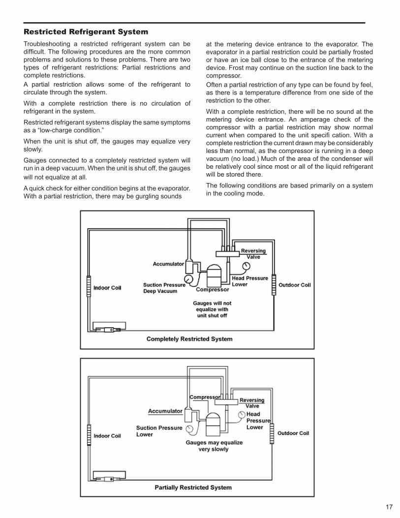
Restricted Refrigerant System
Troubleshooting a restricted refrigerant system can be difficult. The following procedures are the more common problems and solutions to these problems. There are two types of refrigerant restrictions: Partial restrictions and complete restrictions. A partial restriction allows some of the refrigerant to circulate through the system.
With a complete restriction there is no circulation of refrigerant in the system.
Restricted refrigerant systems display the same symptoms as a “low-charge condition.”
When the unit is shut off, the gauges may equalize very slowly.
Gauges connected to a completely restricted system will run in a deep vacuum. When the unit is shut off, the gauges will not equalize at all.
A quick check for either condition begins at the evaporator. With a partial restriction, there may be gurgling sounds
at the metering device entrance to the evaporator. The evaporator in a partial restriction could be partially frosted or have an ice ball close to the entrance of the metering device. Frost may continue on the suction line back to the compressor. Often a partial restriction of any type can be found by feel, as there is a temperature difference from one side of the restriction to the other.
With a complete restriction, there will be no sound at the metering device entrance. An amperage check of the compressor with a partial restriction may show normal current when compared to the unit specifi cation. With a complete restriction the current drawn may be considerably less than normal, as the compressor is running in a deep vacuum (no load.) Much of the area of the condenser will be relatively cool since most or all of the liquid refrigerant will be stored there.
The following conditions are based primarily on a system in the cooling mode.
17
MeTeRING DeVICe
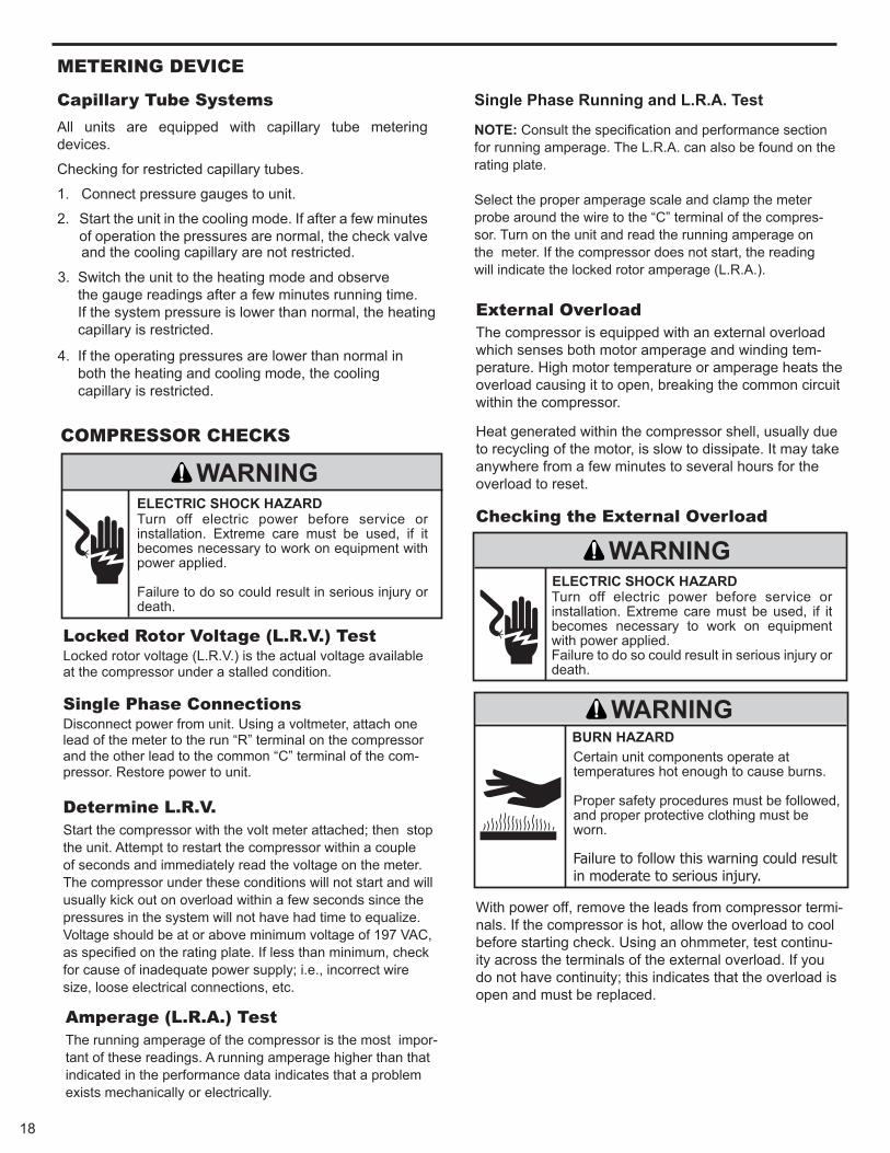
Capillary Tube Systems All units are equipped with capillary tube metering devices.
Checking for restricted capillary tubes.
1. Connect pressure gauges to unit.
2. Start the unit in the cooling mode. If after a few minutes of operation the pressures are normal, the check valve and the cooling capillary are not restricted.
3. Switch the unit to the heating mode and observe the gauge readings after a few minutes running time. If the system pressure is lower than normal, the heating capillary is restricted.
4. If the operating pressures are lower than normal in both the heating and cooling mode, the cooling capillary is restricted.
locked Rotor Voltage (l.R.V.) Test Locked rotor voltage (L.R.V.) is the actual voltage available at the compressor under a stalled condition.
Single Phase Connections Disconnect power from unit. Using a voltmeter, attach one lead of the meter to the run “R” terminal on the compressor and the other lead to the common “C” terminal of the com-pressor. Restore power to unit.
Determine l.R.V. Start the compressor with the volt meter attached; then stop the unit. Attempt to restart the compressor within a couple of seconds and immediately read the voltage on the meter. The compressor under these conditions will not start and will usually kick out on overload within a few seconds since the pressures in the system will not have had time to equalize. Voltage should be at or above minimum voltage of 197 VAC, as specified on the rating plate. If less than minimum, check for cause of inadequate power supply; i.e., incorrect wire size, loose electrical connections, etc.
COMPReSSOR CHeCKS
ELECTRIC SHOCK HAZARD
WARNINGTurn off electric power before service or installation. Extreme care must be used, if it becomes necessary to work on equipment with power applied. Failure to do so could result in serious injury or death.
Amperage (l.R.A.) Test The running amperage of the compressor is the most impor-tant of these readings. A running amperage higher than that indicated in the performance data indicates that a problem exists mechanically or electrically.
Single Phase Running and L.R.A. Test
NOTE: Consult the specification and performance section for running amperage. The L.R.A. can also be found on the rating plate. Select the proper amperage scale and clamp the meter probe around the wire to the “C” terminal of the compres-sor. Turn on the unit and read the running amperage on the meter. If the compressor does not start, the reading will indicate the locked rotor amperage (L.R.A.).
external Overload The compressor is equipped with an external overload which senses both motor amperage and winding tem-perature. High motor temperature or amperage heats the overload causing it to open, breaking the common circuit within the compressor.
Heat generated within the compressor shell, usually due to recycling of the motor, is slow to dissipate. It may take anywhere from a few minutes to several hours for the overload to reset.
Checking the external Overload
With power off, remove the leads from compressor termi-nals. If the compressor is hot, allow the overload to cool before starting check. Using an ohmmeter, test continu-ity across the terminals of the external overload. If you do not have continuity; this indicates that the overload is open and must be replaced.
Certain unit components operate at temperatures hot enough to cause burns.
Proper safety procedures must be followed, and proper protective clothing must be worn.
Failure to follow this warning could result in moderate to serious injury.
WARNINGBURN HAZARD
ELECTRIC SHOCK HAZARD
WARNINGTurn off electric power before service or installation. Extreme care must be used, if it becomes necessary to work on equipment with power applied.Failure to do so could result in serious injury or death.
18
19
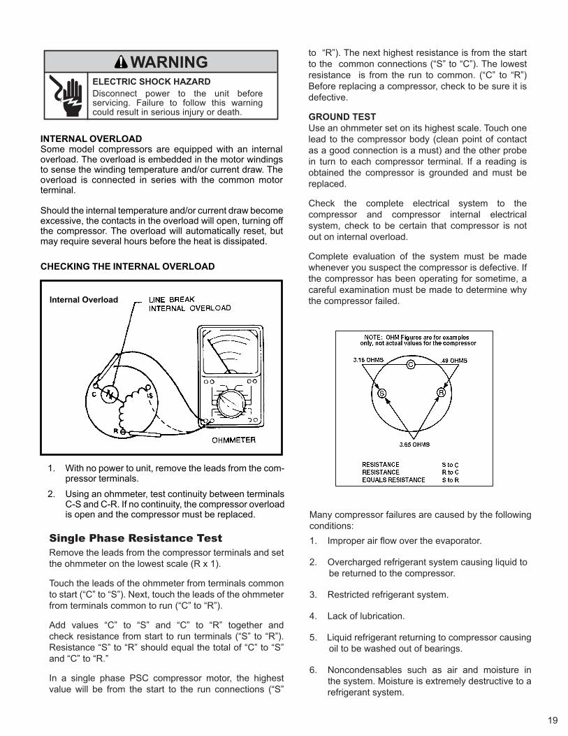
1. With no power to unit, remove the leads from the com-pressor terminals.
2. Using an ohmmeter, test continuity between terminalsC-S and C-R. If no continuity, the compressor overloadis open and the compressor must be replaced.
CHECKING THE INTERNAL OVERLOAD
INTERNAL OVERLOADSome model compressors are equipped with an internaloverload. The overload is embedded in the motor windingsto sense the winding temperature and/or current draw. Theoverload is connected in series with the common motorterminal.
Should the internal temperature and/or current draw becomeexcessive, the contacts in the overload will open, turning offthe compressor. The overload will automatically reset, butmay require several hours before the heat is dissipated.
Internal Overload
Single Phase Resistance Test Remove the leads from the compressor terminals and set the ohmmeter on the lowest scale (R x 1).
Touch the leads of the ohmmeter from terminals common to start (“C” to “S”). Next, touch the leads of the ohmmeter from terminals common to run (“C” to “R”).
Add values “C” to “S” and “C” to “R” together and check resistance from start to run terminals (“S” to “R”). Resistance “S” to “R” should equal the total of “C” to “S” and “C” to “R.”
In a single phase PSC compressor motor, the highest value will be from the start to the run connections (“S”
to “R”). The next highest resistance is from the start to the common connections (“S” to “C”). The lowest resistance is from the run to common. (“C” to “R”) Before replacing a compressor, check to be sure it is defective.
GROUND TESTUse an ohmmeter set on its highest scale. Touch one lead to the compressor body (clean point of contact as a good connection is a must) and the other probe in turn to each compressor terminal. If a reading is obtained the compressor is grounded and must be replaced.
Check the complete electrical system to the compressor and compressor internal electrical system, check to be certain that compressor is not out on internal overload.
Complete evaluation of the system must be made whenever you suspect the compressor is defective. If the compressor has been operating for sometime, a careful examination must be made to determine why the compressor failed.
Many compressor failures are caused by the following conditions: 1. Improper air flow over the evaporator.
2. Overcharged refrigerant system causing liquid to be returned to the compressor.
3. Restricted refrigerant system.
4. Lack of lubrication.
5. Liquid refrigerant returning to compressor causing oil to be washed out of bearings.
6. Noncondensables such as air and moisture in the system. Moisture is extremely destructive to a refrigerant system.
ELECTRIC SHOCK HAZARD
WARNING
Disconnect power to the unit before servicing. Failure to follow this warning could result in serious injury or death.
CAPACITORS CAPACITORS
Many motor capacitors are internally fused. Shorting the terminals will blow the fuse, ruining the capacitor. A 20,000 ohm 2 watt resistor can be used to discharge capacitors safely. Remove wires from capacitor and place resistor across terminals. When checking a dual capacitor with a capacitor analyzer or ohmmeter, both sides must be tested.
Capacitor Check with Capacitor AnalyzerThe capacitor analyzer will show whether the capacitor is “open” or “shorted.” It will tell whether the capacitor is within its micro farads rating and it will show whether the capacitor is operating at the proper power-factor percentage. The instrument will automatically discharge the capacitor when the test switch is released.
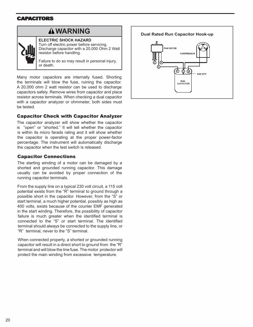
Capacitor Connections The starting winding of a motor can be damaged by a shorted and grounded running capacitor. This damage usually can be avoided by proper connection of the running capacitor terminals.
From the supply line on a typical 230 volt circuit, a 115 volt potential exists from the “R” terminal to ground through a possible short in the capacitor. However, from the “S” or start terminal, a much higher potential, possibly as high as 400 volts, exists because of the counter EMF generated in the start winding. Therefore, the possibility of capacitor failure is much greater when the identified terminal is connected to the “S” or start terminal. The identified terminal should always be connected to the supply line, or “R” terminal, never to the “S” terminal.
When connected properly, a shorted or grounded running capacitor will result in a direct short to ground from the “R” terminal and will blow the line fuse. The motor protector will protect the main winding from excessive temperature.
ELECTRIC SHOCK HAZARD
WARNINGTurn off electric power before servicing. Discharge capacitor with a 20,000 Ohm 2 Watt resistor before handling.
Failure to do so may result in personal injury, or death.
20
Dual Rated Run Capacitor Hook-up
F C H
21
Recommended procedure for compressor replacement
1. Be certain to perform all necessary electrical and refrigeration tests to be sure the compressor is actually defective before replacing.
2. Recover all refrigerant from the system though the process tubes. PROPER HANDLING OF RECOVERED REFRIGERANT ACCORDING TO EPA REGULATIONS IS REQUIRED. Do not use gauge manifold for this purpose if there has been a burnout. You will contaminate your manifold and hoses. Use a Schrader valve adapter and copper tubing for burnout failures.
3. After all refrigerant has been recovered, disconnect suction and discharge lines from the compressor and remove compressor. Be certain to have both suction and discharge process tubes open to atmosphere.
4. Carefully pour a small amount of oil from the suction stub of the defective compressor into a clean container.
9. Evacuate the system with a good vacuum pump capable of a final vacuum of 300 microns or less. The system should be evacuated through both liquid line and suction line gauge ports. While the unit is being evacuated, seal all openings on the defective compressor. Compressor manufacturers will void warranties on units received not properly sealed. Do not distort the manufacturers tube connections.
10. Recharge the system with the correct amount of refrigerant. The proper refrigerant charge will be found on the unit rating plate. The use of an accurate
measuring device, such as a charging cylinder, electronic scales or similar device is necessary.
COMPReSSOR RePlACeMeNT
5. Using an acid test kit (one shot or conventional kit), test the oil for acid content according to the instructions with the kit.
6. If any evidence of a burnout is found, no matter how slight, the system will need to be cleaned up following proper procedures.
7. Install the replacement compressor.
8. Pressurize with a combination of R-22 and nitrogen and leak test all connections with an electronic or Halide leak detector. Recover refrigerant and repair any leaks found. Repeat Step 8 to insure no more leaks are present.
Unplug and/or disconnect all electrical power to the unit before performing inspections, maintenances or service. Failure to do so could result in electric shock, serious injury or death.
WARNINGRISK OF ELECTRIC SHOCK
Sealed Refrigeration System contains refrigerant and oil under high pressure.
Proper safety procedures must be followed, and proper protective clothing must be worn when working with refrigerants.
Failure to follow these procedures could result in serious injury or death.
WARNINGHIGH PRESSURE HAZARD
Extreme care, proper judgment and all safety procedures must be followed when testing, troubleshooting, handling or working around unit while in operation with high temperature components. Wear protective safety aids such as: gloves, clothing etc.
Failure to do so could result in serious burn injury.
WARNINGHIGH TEMPERATURES
The use of a torch requires extreme care and proper judgment. Follow all safety recommended precautions and protect surrounding areas with fire proof materials. Have a fire extinguisher readily available. Failure to follow this notice could result in moderate to serious property damage.
NOTICEFIRE HAZARD
The use of nitrogen requires a pressureregulator. Follow all safety procedures and wear protective safety clothing etc.
Failure to follow proper safety procedures result in serious injury or death.
WARNINGEXPLOSION HAZARD
Proper safety procedures must be followed, and proper protective clothing must be worn when working with liquid refrigerant.
Failure to follow these procedures could result in minor to moderate injury.
CAUTIONFREEZE HAZARD

1.
2.
3.
4.
5.
ELECTRIC SHOCK HAZARD
WARNINGTurn off electric power before service or installation.
Failure to do so may result in personal injury, or death.
Sealed Refrigeration System contains refrigerant and oil under high pressure.
Proper safety procedures must be followed, and proper protective clothing must be worn when working with refrigerants.
Failure to follow these procedures could result in serious injury or death.
WARNINGHIGH PRESSURE HAZARD
The use of nitrogen requires a pressureregulator. Follow all safety procedures and wear protective safety clothing etc.
Failure to follow proper safety procedures result in serious injury or death.
WARNINGEXPLOSION HAZARD
Recover all refrigerant and oil from the system. Remove compressor, capillary tube and filter drier from the system. Flush evaporator condenser and all connecting tubing with dry nitrogen or equivalent. Use approved flushing agent to remove all contamination from system. Inspect suction and discharge line for carbon deposits. Remove and clean if necessary. Ensure all acid is neutralized. Reassemble the system, including new drier strainer and capillary tube.
Proceed with step 9-10 above. (see page #22).
SPECIAL PROCEDURE IN THE CASE OF MOTOR COMPRESSOR BURNOUT
Basically, troubleshooting and servicing rotary compres-sors is the same as on the reciprocating compressor with only one main exception:NEVER, under any circumstances, charge a rotary com-pressor through the LOW side. Doing so would cause permanent damage to the new compressor.
ROTARY COMPRESSOR SPECIAL TROUBLESHOOTING AND SERVICE
22
23
ROUTINe MAINTeNANCe
AIR FILTER Clean the unit air intake filter at least every 300 to 350 hours of operation. Clean the filters with a mild detergent in warm water and allow to dry thoroughly before reinstalling.
Units are to be inspected and serviced by qualified service personnel only. Use proper protection on surrounding property. Failure to follow this notice could result in moderate or serious property damage.
Do not use a caustic coil cleaning agent on coils or base pan. Use a biodegradable cleaning agent and degreaser, to prevent damage to the coil and/or base pan.
NOTICE
NOTICE
BLOWER WHEEL / HOUSING / CONDENSER FAN / SHROUD Inspect the indoor blower housing, evaporator blade, condenser fan blade and condenser shroud periodically (yearly or bi-yearly) and clean of all debris (lint, dirt, mold, fungus, etc.). Clean the blower housing area and blower wheel with an antibacterial / antifungal cleaner. Use a biodegradable cleaning agent and degreaser on condenser fan and condenser shroud. Use warm or cold water when rinsing these items. Allow all items to dry thoroughly before reinstalling them.
The indoor coil (evaporator coil), the outdoor coil (condenser coil) and base pan should be inspected periodically (yearly or bi-yearly) and cleaned of all debris (lint, dirt, leaves, paper, etc.). Clean the coils and base pan with a soft brush and compressed air or vacuum. If using a pressure washer, be careful not to bend the aluminium fin pack. Use a sweeping up and down motion in the direction of the vertical aluminum fin pack when pressure cleaning coils. Cover all electrical components to protect them from water or spray. Allow the unit to dry thoroughly before reinstalling it in the sleeve.
EXCESSIVE WEIGHT HAZARD
WARNINGUse two people to lift or carry the unit, and wear proper protective clothing.
Failure to do so may result in personal injury.
ELECTRIC SHOCK HAZARD
WARNINGTurn off electric power before inspections, maintenances, or service.
Extreme care must be used, if it becomes necessary to work on equipment with power applied.
Failure to do so could result in serious injury or death.
ELECTRONIC / ELECTRICAL / MECHANICAL
COILS AND BASE PAN
Periodically (at least yearly or bi-yearly): inspect all control components: electronic, electrical and mechanical, as well as the power supply. Use proper testing instruments (voltmeter, ohmmeter, ammeter, wattmeter, etc.) to perform elec-trical tests. Use an air conditioning or refrigeration thermometer to check room, outdoor and coil operating tempera-tures. Use a sling psychrometer to measure wet bulb temperatures indoors and outdoors.
Inspect the surrounding area (inside and outside) to ensure that the unit’s clearances have not been compromised or altered.
CUT/SEVER HAZARD
WARNINGBe careful with the sharp edges and corners. Wear protective clothing and gloves, etc.
Failure to do so could result in serious injury.
24
Cabinet
Air inlet louver
Front grille
Power cord
Control panel cover
Front intake grille
Air filter(behind front intake grille)
SLEEVE / DRAIN Inspect the sleeve and drain system periodically (at least yearly or bi-yearly) and clean of all obstructions and debris. Clean both areas with an antibacterial and antifungal cleaner. Rinse both items thoroughly with water and ensure that the drain outlets are operating correctly. Check the sealant around the sleeve and reseal areas as needed.
FRONT COVER Clean the front cover when needed. Use a mild detergent. Wash and rinse with warm water. Allow it to dry thoroughly before reinstalling it in the chassis.
ROUTINe MAINTeNANCe (Continued)
Do not drill holes in the bottom of the drain pan or the underside of the unit. Not following this notice could result in damage to the unit or condensate water leaking inappropriately which could cause water damage to surrounding property.
NOTICE
25
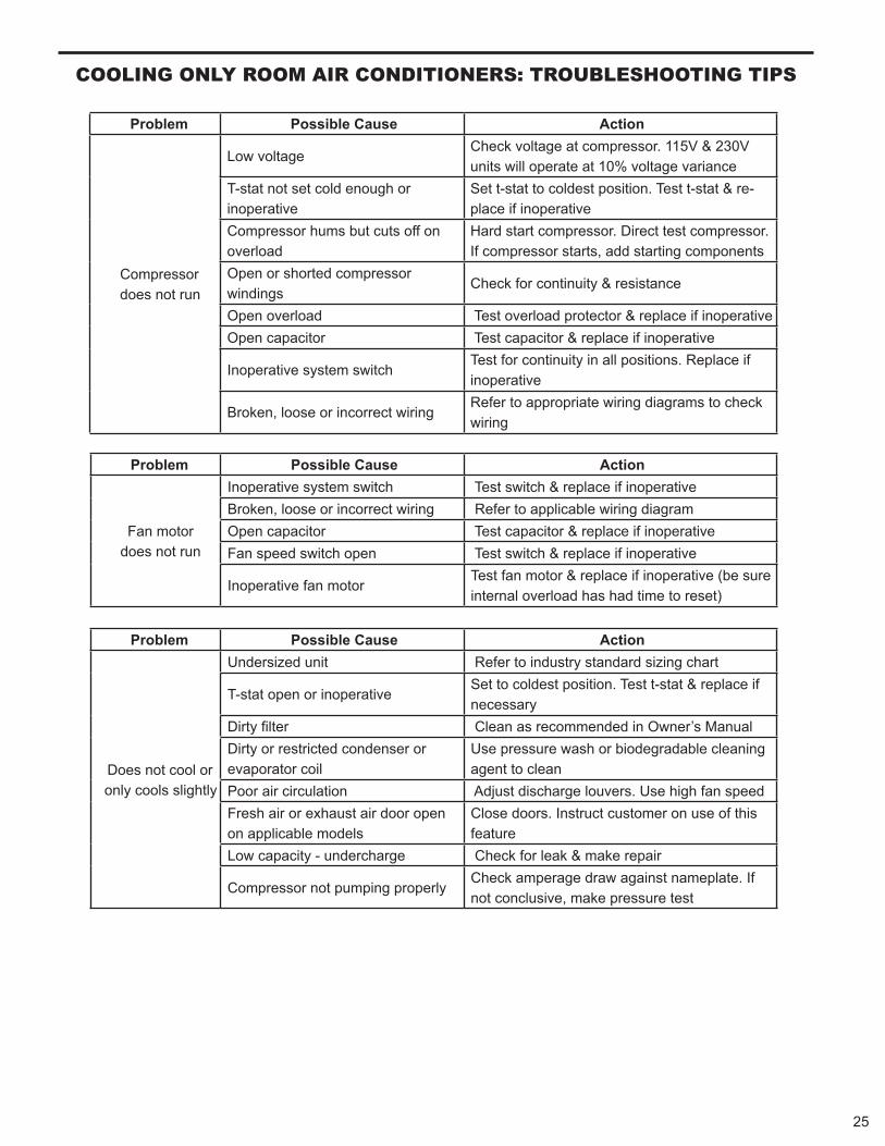
COOlING ONlY ROOM AIR CONDITIONeRS: TROUBleSHOOTING TIPS
noitcA esuaC elbissoP melborP
Compressordoes not run
Low voltage Check voltage at compressor. 115V & 230V units will operate at 10% voltage variance
T-stat not set cold enough or inoperative
Set t-stat to coldest position. Test t-stat & re- place if inoperative
Compressor hums but cuts off on overload
Hard start compressor. Direct test compressor. If compressor starts, add starting components
Open or shorted compressorwindings
Check for continuity & resistance
Open overload Test overload protector & replace if inoperative Open capacitor Test capacitor & replace if inoperative
Inoperative system switch Test for continuity in all positions. Replace if inoperative
Broken, loose or incorrect wiring Refer to appropriate wiring diagrams to check wiring
noitcA esuaC elbissoP melborP
Fan motordoes not run
Inoperative system switch Test switch & replace if inoperative Broken, loose or incorrect wiring Refer to applicable wiring diagram Open capacitor Test capacitor & replace if inoperative Fan speed switch open Test switch & replace if inoperative
Inoperative fan motor Test fan motor & replace if inoperative (be sure internal overload has had time to reset)
noitcA esuaC elbissoP melborP
Does not cool or only cools slightly
Undersized unit Refer to industry standard sizing chart
T-stat open or inoperative Set to coldest position. Test t-stat & replace if necessary
Dirty fi launaM s’renwO ni dednemmocer sa naelC retl Dirty or restricted condenser orevaporator coil
Use pressure wash or biodegradable cleaning agent to clean
Poor air circulation Adjust discharge louvers. Use high fan speed Fresh air or exhaust air door openon applicable models
Close doors. Instruct customer on use of this feature
Low capacity - undercharge Check for leak & make repair
Compressor not pumping properly Check amperage draw against nameplate. Ifnot conclusive, make pressure test
26
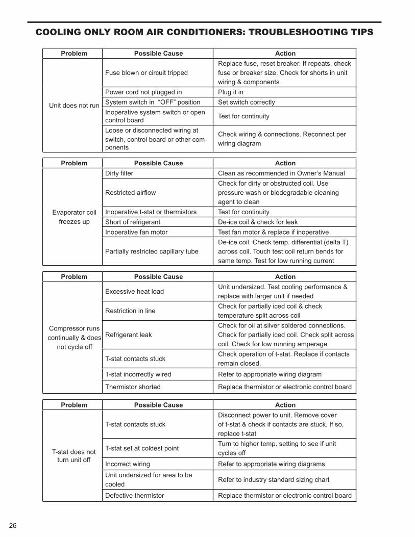
COOlING ONlY ROOM AIR CONDITIONeRS: TROUBleSHOOTING TIPS
noitcA esuaC elbissoP melborP
Unit does not run
Fuse blown or circuit tripped Replace fuse, reset breaker. If repeats, check fuse or breaker size. Check for shorts in unit wiring & components
Power cord not plugged in Plug it in System switch in “OFF” position Set switch correctly Inoperative system switch or open control board Test for continuity
Loose or disconnected wiring at switch, control board or other com-ponents
Check wiring & connections. Reconnect per wiring diagram
noitcA esuaC elbissoP melborP
Evaporator coilfreezes up
Dirty fi launaM s’renwO ni dednemmocer sa naelC retl
Restricted airfl ow Check for dirty or obstructed coil. Use pressure wash or biodegradable cleaning agent to clean
Inoperative t-stat or thermistors Test for continuity Short of refrigerant De-ice coil & check for leak Inoperative fan motor Test fan motor & replace if inoperative
Partially restricted capillary tube De-ice coil. Check temp. differential (delta T) across coil. Touch test coil return bends for same temp. Test for low running current
noitcA esuaC elbissoP melborP
Compressor runs continually & does
not cycle off
Excessive heat load Unit undersized. Test cooling performance & replace with larger unit if needed
Restriction in line Check for partially iced coil & check temperature split across coil
Refrigerant leak Check for oil at silver soldered connections. Check for partially iced coil. Check split across coil. Check for low running amperage
T-stat contacts stuck Check operation of t-stat. Replace if contacts remain closed.
T-stat incorrectly wired Refer to appropriate wiring diagram
Thermistor shorted Replace thermistor or electronic control board
noitcA esuaC elbissoP melborP
T-stat does not turn unit off
T-stat contacts stuck Disconnect power to unit. Remove cover of t-stat & check if contacts are stuck. If so, replace t-stat
T-stat set at coldest point Turn to higher temp. setting to see if unit cycles off
Incorrect wiring Refer to appropriate wiring diagrams
Unit undersized for area to becooled
Refer to industry standard sizing chart
Defective thermistor Replace thermistor or electronic control board
27
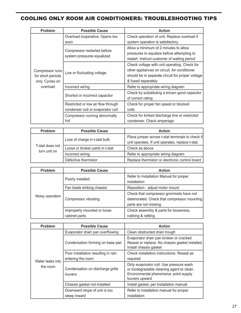
COOlING ONlY ROOM AIR CONDITIONeRS: TROUBleSHOOTING TIPS
noitcA esuaC elbissoP melborP
Compressor runs for short periods only. Cycles on
overload
Overload inoperative. Opens toosoon
Check operation of unit. Replace overload if system operation is satisfactory
Compressor restarted before system pressures equalized
Allow a minimum of 2 minutes to allow pressures to equalize before attempting to restart. Instruct customer of waiting period
Low or uctuating voltage
Check voltage with unit operating. Check for other appliances on circuit. Air conditioner should be in separate circuit for proper voltage & fused separately
Incorrect wiring Refer to appropriate wiring diagram
Shorted or incorrect capacitor Check by substituting a known good capacitor of correct rating
Restricted or low air ow through condenser coil or evaporator coil
Check for proper fan speed or blocked coils
Compressor running abnormally hot
Check for kinked discharge line or restricted condenser. Check amperage
noitcA esuaC elbissoP melborP
T-stat does not turn unit on
Loss of charge in t-stat bulb Place jumper across t-stat terminals to check if unit operates. If unit operates, replace t-stat.
Loose or broken parts in t-stat Check as above Incorrect wiring Refer to appropriate wiring diagram Defective thermistor Replace thermistor or electronic control board
noitcA esuaC elbissoP melborP
Noisy operation
Poorly installed Refer to Installation Manual for proper installation
Fan blade striking chassis Reposition - adjust motor mount
Compressor vibrating Check that compressor grommets have not deteriorated. Check that compressor mounting parts are not missing
Improperly mounted or loosecabinet parts
Check assembly & parts for looseness, rubbing & rattling
noitcA esuaC elbissoP melborP
Water leaks into the room
Evaporator drain pan over owing Clean obstructed drain trough
Condensation forming on base pan Evaporator drain pan broken or cracked. Reseal or replace. No chassis gasket installed. Install chassis gasket
Poor installation resulting in rain entering the room
Check installation instructions. Reseal as required
Condensation on discharge grille louvers
Dirty evaporator coil. Use pressure wash or biodegradable cleaning agent to clean. Environmental phenomena: point supply louvers upward
Chassis gasket not installed Install gasket, per Installation manual Downward slope of unit is toosteep inward
Refer to installation manual for proper installation
COOlING ONlY ROOM AIR CONDITIONeRS: TROUBleSHOOTING TIPS
noitcA esuaC elbissoP melborP
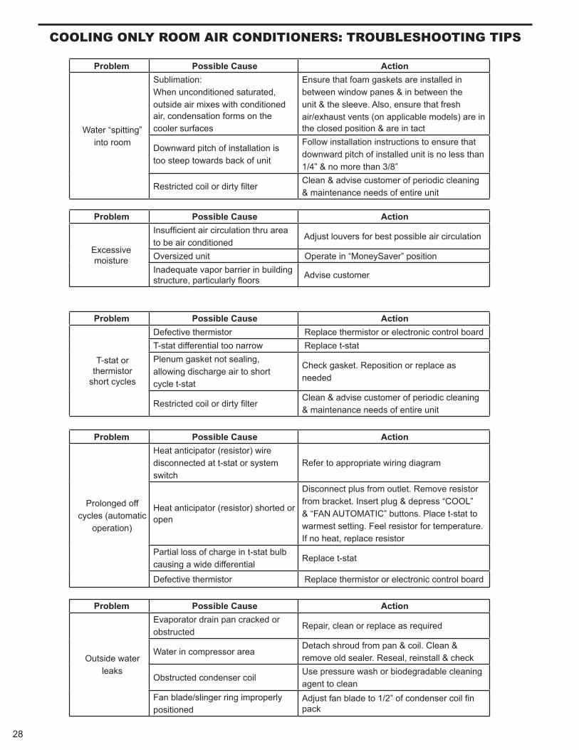
Water “spitting” into room
Sublimation:When unconditioned saturated,outside air mixes with conditioned air, condensation forms on the cooler surfaces
Ensure that foam gaskets are installed inbetween window panes & in between the unit & the sleeve. Also, ensure that fresh air/exhaust vents (on applicable models) are in the closed position & are in tact
Downward pitch of installation istoo steep towards back of unit
Follow installation instructions to ensure that downward pitch of installed unit is no less than 1/4” & no more than 3/8”
Restricted coil or dirty fi lter Clean & advise customer of periodic cleaning & maintenance needs of entire unit
noitcA esuaC elbissoP melborP
Excessivemoisture
Insuffi cient air circulation thru area to be air conditioned
Adjust louvers for best possible air circulation
noitisop ”revaSyenoM“ ni etarepO tinu dezisrevOInadequate vapor barrier in building structure, particularly fl oors Advise customer
noitcA esuaC elbissoP melborP
T-stat or thermistor
short cycles
Defective thermistor Replace thermistor or electronic control boardT-stat differential too narrow Replace t-stat Plenum gasket not sealing, allowing discharge air to shortcycle t-stat
Check gasket. Reposition or replace as needed
Restricted coil or dirty fi lter Clean & advise customer of periodic cleaning & maintenance needs of entire unit
noitcA esuaC elbissoP melborP
Prolonged off cycles (automatic
operation)
Heat anticipator (resistor) wiredisconnected at t-stat or systemswitch
Refer to appropriate wiring diagram
Heat anticipator (resistor) shorted or open
Disconnect plus from outlet. Remove resistorfrom bracket. Insert plug & depress “COOL” & “FAN AUTOMATIC” buttons. Place t-stat to warmest setting. Feel resistor for temperature. If no heat, replace resistor
Partial loss of charge in t-stat bulb causing a wide differential
Replace t-stat
Defective thermistor Replace thermistor or electronic control board
noitcA esuaC elbissoP melborP
Outside waterleaks
Evaporator drain pan cracked orobstructed
Repair, clean or replace as required
Water in compressor area Detach shroud from pan & coil. Clean & remove old sealer. Reseal, reinstall & check
Obstructed condenser coil Use pressure wash or biodegradable cleaning agent to clean
Fan blade/slinger ring improperly positioned
Adjust fan blade to 1/2” of condenser coil fi n pack
28
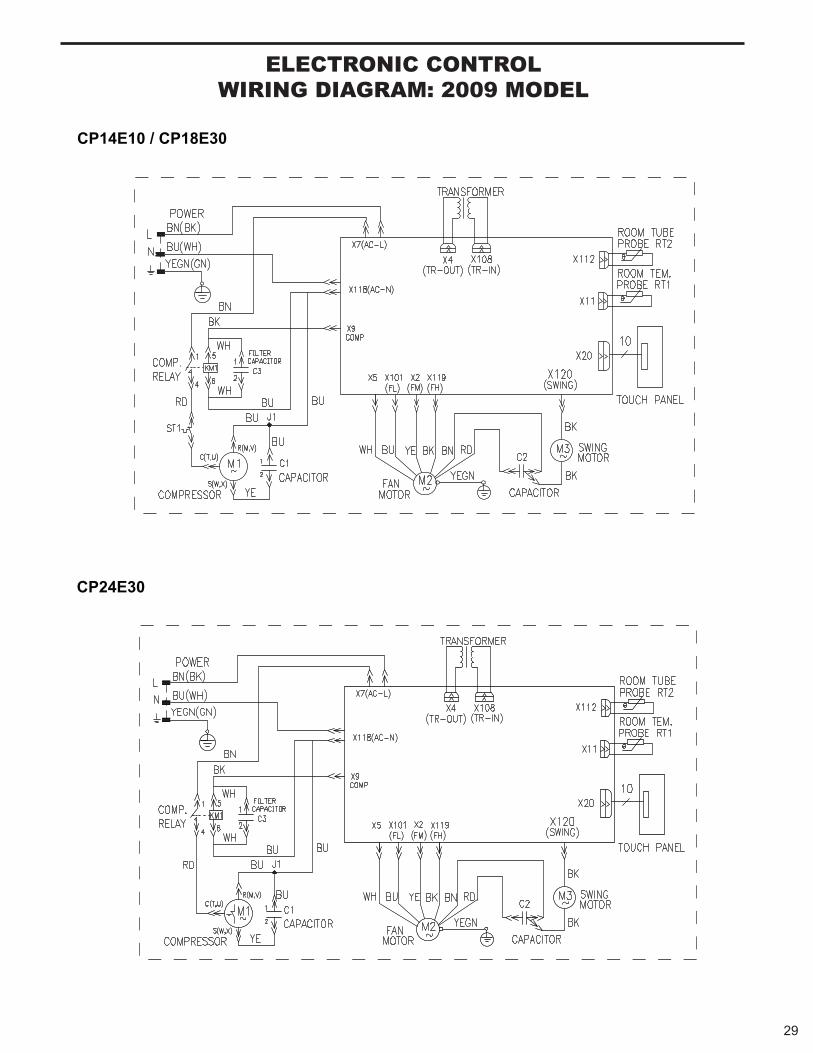
29
eleCTRONIC CONTROlWIRING DIAGRAM: 2009 MODel
CP24E30
CP14E10 / CP18E30
30
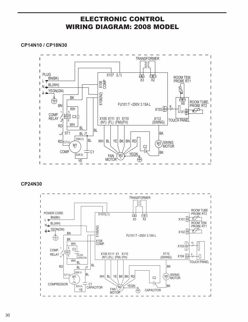
eleCTRONIC CONTROlWIRING DIAGRAM: 2008 MODel
CP24N30
CP14N10 / CP18N30
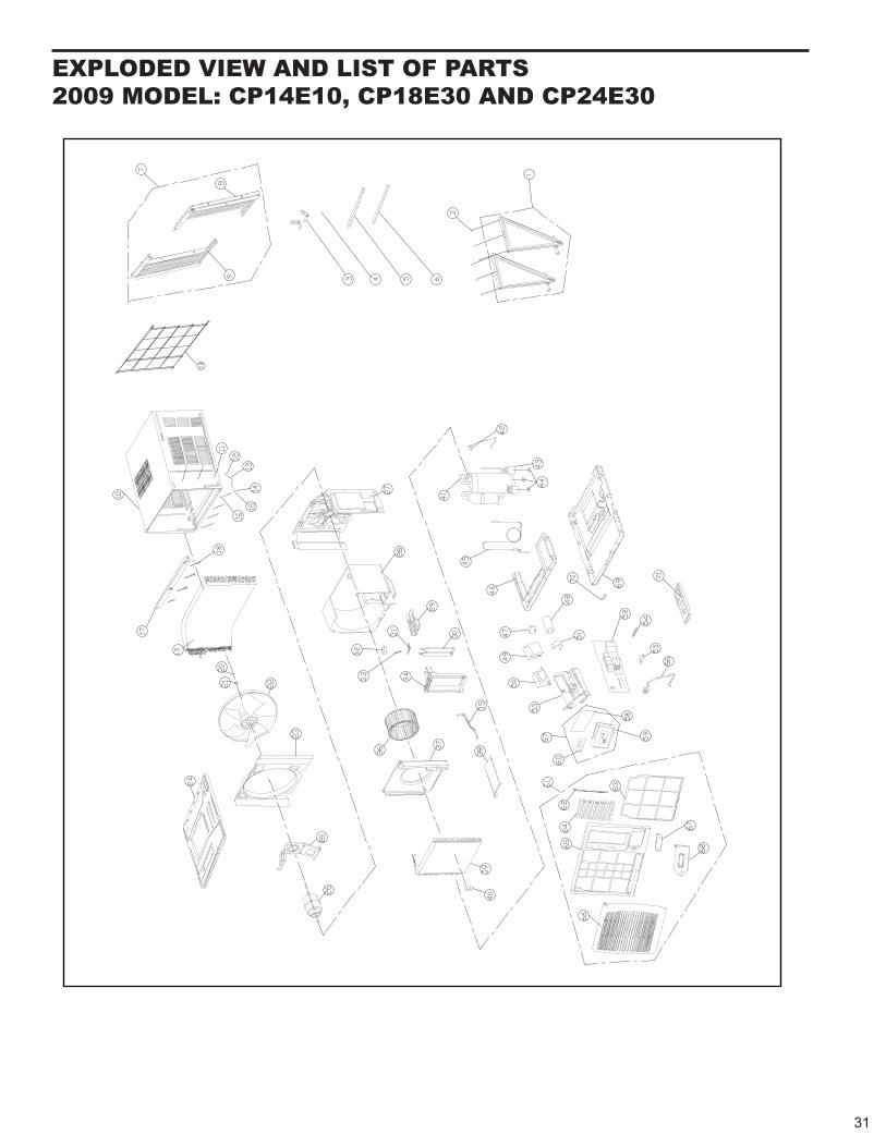
eXPlODeD VIeW AND lIST Of PARTS 2009 MODel: CP14e10, CP18e30 AND CP24e30
31
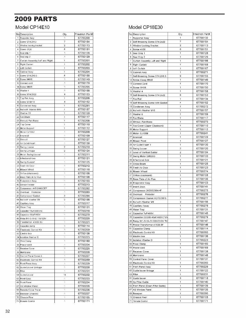
2009 PARTS
32
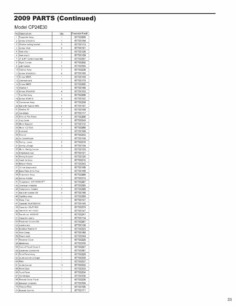
2009 PARTS (Continued)
33
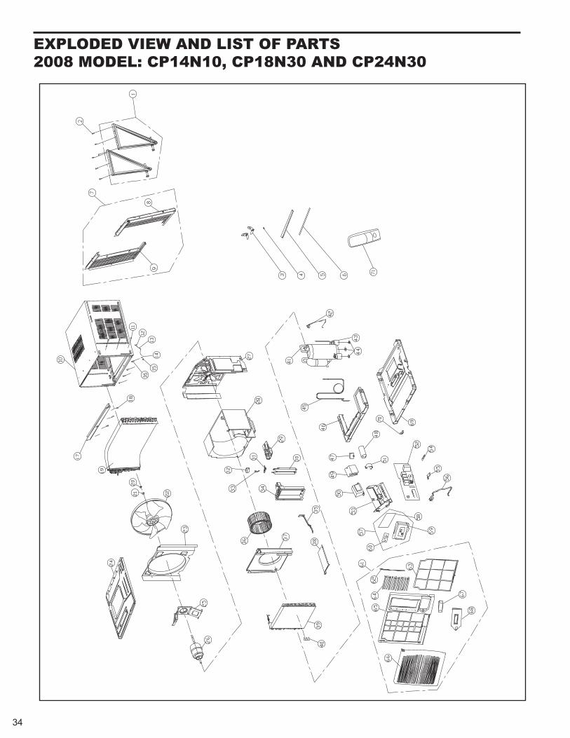
eXPlODeD VIeW AND lIST Of PARTS 2008 MODel: CP14N10, CP18N30 AND CP24N30
34
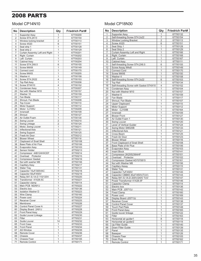
2008 PARTS
#traP hcirdeirFytQnoitpircseDoN002007761yssA retroppuS145100776731X2.4TS wercS2311007762tekcarb gnikcol wodniW315100776602X4 wercS48210077611 pirts laeS59210077612 pirts laeS6102007761thgiR dna tfeL ybmessA niatruC7202007761 niatruC thgiR8302007761 niatruC tfeL9402007761yssA tenibaC015510077665.6X2.4TS wercS119410077618X4M wercS21071007761droc tcennoC315020077615X4M wercS418510077614 rehsaW5135100776422X2.4TS wercS61602007761yssA liaR poT7125100776401X4TS wercS81702007761yssA resnednoC9175100776101M rehsaW htiw tuN0295100776101 rehsaW12711007761edalB naF22802007761edalB naF ,duorhS32011007761revoC poT42211007761troppuS rotoM52902007761U001JC rotoM62901007761llawrennI72721007761duorhS82031007761maoF teltuO riA92012007762revuoL gniwS03421007762egakniL gniwS13
32 Motor, Swing Louver 1 6770021133 Infl 121007761sixA lanoitce
521007761troppuS gniwS43212007761rooD riA hserF53611007761leehW rewolB63
Model CP14N10 Model CP18N30
801007761llehS lianS fo draobpalC73601007761eulF riA fo etalP esaB83301007761yssA rotaropavE93312007761redloH rosneS04412007761 FECXH421B44 rosserpmoC14512007761 rotcetorP daolrevO24612007763teksaG rosserpmoC346510077638M rehsaw htiw tuN44712007761yssA yrallipaC54131007761yarT retaW64812007761CAV003/Fu51 roticapaC74912007761V054/Fu05 roticapaC84022007761V021/011 D-A1-S-148 yaleR94122007761 C5.62X14 remrofsnarT05411007761pmalc roticapaC15222007761J19A2M BCP niaM25631007761xob cirtcelE35322007761D rehsaW noitalosI45061007761pmalC eriW55422007761droc rewoP65522007761revoC revieceR75622007761enarbmeM85722007761A revoC lenaP lortnoC95822007761 J19A2 draoB yalpsiD06922007761yssA lenaP tnorF16032007761egakniL revuoL ediuG26132007761retliF362320077641revuoL ediuG46332007761esaC tnorF56
66 432007761lenaP tnorF532007761wodniW SA76632007761revoC etomeR86732007761sissahC96501007761rexiF sissahC07171007761lortnoC etomeR17
#traP hcirdeirFytQnoitpircseDoN231007761yssA retroppuS145100776722x2.4TS wercS gnidaerht-fleS2311007762tekcarB gnikcoL wodniW315100776602X4 wercS48210077611 pirtS laeS59210077612 pirtS laeS6661007761thgiR dna tfeL ybmessA niatruC7861007761 niatruC thgiR8761007761 niatruC tfeL9111007761yssA tenibaC015510077665.6X2.4TS wercS gnidaerht-fleS119410077618x4M yassA wercS21071007761droC tcennoC310510077616X4M wercS418510077614 rehsaW5135100776622x2.4TS wercS gnidaerht-fleS61431007761liaR poT7125100776401X4TS teksaG htiw wercS gnidaerht-fleS81401007761yssA resnednoC9175100776101M rehsaW htiw tuN029510077616 rehsaW12711007761edalB naF22701007761edalB naF ,duorhS32011007761draobpalC reppU42211007761troppuS rotoM52461007761B001JC rotoM62901007761llawrennI72721007761tnorF rewolB820310077611 maoF teltuO riA92021007762revuoL gniwS03421007762rediuG lacitreV fo reveL13
32 Swing Motor SM020B 1 6770013333 Infl 121007761sixA lanoitce
521007761maeB ssorC43321007761rooD riA hserF53611007761leehW rewolB63801007761llehS lianS fo draobpalC tnorF73601007761eulF riA fo etalP esaB83301007761yssA rotaropavE93141007762kcolB tresnI04101007761FHA632S52K2 rosserpmoC14201007761rotcetorP daolrevO241610077635180707DA teksaG rosserpmoC346510077638M rehsaW htiw tuN44511007761yassA yrallipaC54131007761yarT retaW64541007761V054/Fu7 roticapaC74441007761)VUT(V054/Fu04 56BBC roticapaC84741007761VUT V042/V002 D-A1-S-148 yaleR94641007761F5.62X14 remrofsnarT rewoP05411007761pmalC roticapaC15631007761xob cirtcelE25241007761J31752J BCP niaM35061007761pmalC dexiF45961007761droc rewoP55341007761J31752J draoB yalpsiD65831007761revoC revieceR75731007761revoC lenaP lortnoC85841007761etalP daP hcuoT95561007761yssA lenaP tnorF06221007761egaknil revuol ediuG16361007761retliF268110077681rediug ria latnoziroH369110077612rediug ria latnoziroH46041007761ediuG retliF pU56
66 931007761ediuG retliF nwoD531007761lenaP76621007761napesaB86501007761rexiF sissahC96261007761gulP niarD07171007761lortnoC etomeR17
35
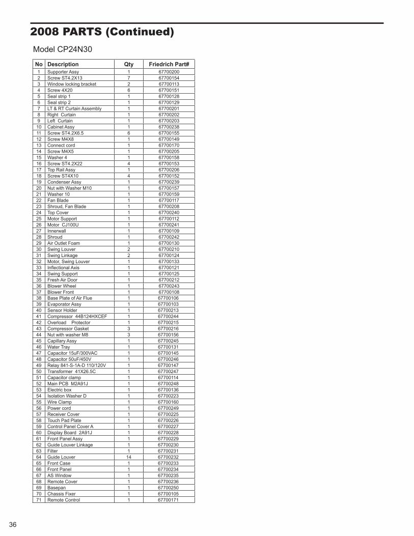
2008 PARTS (Continued)
#traP hcirdeirFytQnoitpircseDoN002007761yssA retroppuS145100776731X2.4TS wercS2311007762tekcarb gnikcol wodniW315100776602X4 wercS48210077611 pirts laeS59210077612 pirts laeS6102007761ylbmessA niatruC TR & TL7202007761 niatruC thgiR8302007761 niatruC tfeL9832007761yssA tenibaC015510077665.6X2.4TS wercS119410077618X4M wercS21071007761droc tcennoC315020077615X4M wercS418510077614 rehsaW5135100776422X2.4TS wercS61602007761yssA liaR poT7125100776401X4TS wercS81932007761yssA resnednoC9175100776101M rehsaW htiw tuN0295100776101 rehsaW12711007761edalB naF22802007761edalB naF ,duorhS32042007761revoC poT42211007761troppuS rotoM52142007761U001JC rotoM62901007761llawrennI72242007761duorhS82031007761maoF teltuO riA92012007762revuoL gniwS03421007762egakniL gniwS13
32 Motor, Swing Louver 1 6770013333 Infl 121007761sixA lanoitce
521007761troppuS gniwS43212007761rooD riA hserF53342007761leehW rewolB63801007761tnorF rewolB73
Model CP24N30
601007761eulF riA fo etalP esaB83301007761yssA rotaropavE93312007761redloH rosneS04442007761 FECXH421B44 rosserpmoC14512007761 rotcetorP daolrevO24612007763teksaG rosserpmoC346510077638M rehsaw htiw tuN44542007761yssA yrallipaC54131007761yarT retaW64541007761CAV003/Fu51 roticapaC74642007761V054/Fu05 roticapaC84741007761V021/011 D-A1-S-148 yaleR94742007761 C5.62X14 remrofsnarT05411007761pmalc roticapaC15842007761J19A2M BCP niaM25631007761xob cirtcelE35322007761D rehsaW noitalosI45061007761pmalC eriW55942007761droc rewoP65522007761revoC revieceR75622007761etalP daP hcuoT85722007761A revoC lenaP lortnoC95822007761 J19A2 draoB yalpsiD06922007761yssA lenaP tnorF16032007761egakniL revuoL ediuG26132007761retliF362320077641revuoL ediuG46332007761esaC tnorF56
66 432007761lenaP tnorF532007761wodniW SA76632007761revoC etomeR86052007761napesaB96501007761rexiF sissahC07171007761lortnoC etomeR17
36
Friedrich Air Conditioning Company P.O. Box 1540
San Antonio, TX 78295 210.357.4400
www.friedrich.com
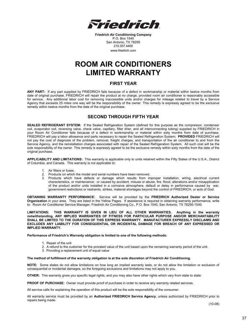
ROOM AIR CONDITIONERS LIMITED WARRANTY
FIRST YEAR
ANY PART: If any part supplied by FRIEDRICH fails because of a defect in workmanship or material within twelve months from date of original purchase, FRIEDRICH will repair the product at no charge, provided room air conditioner is reasonably accessiblefor service. Any additional labor cost for removing inaccessible units and/or charges for mileage related to travel by a ServiceAgency that exceeds 25 miles one way will be the responsibility of the owner. This remedy is expressly agreed to be the exclusiveremedy within twelve months from the date of the original purchase.
SECOND THROUGH FIFTH YEAR
SEALED REFRIGERANT SYSTEM: If the Sealed Refrigeration System (defined for this purpose as the compressor, condenser coil, evaporator coil, reversing valve, check valve, capillary, filter drier, and all interconnecting tubing) supplied by FRIEDRICH in your Room Air Conditioner fails because of a defect in workmanship or material within sixty months from date of purchase, FRIEDRICH will pay a labor allowance and parts necessary to repair the Sealed Refrigeration System; PROVIDED FRIEDRICH will not pay the cost of diagnosis of the problem, removal, freight charges, and transportation of the air conditioner to and from theService Agency, and the reinstallation charges associated with repair of the Sealed Refrigeration System. All such cost will be the sole responsibility of the owner. This remedy is expressly agreed to be the exclusive remedy within sixty months from the date of the original purchase.
APPLICABILITY AND LIMITATIONS: This warranty is applicable only to units retained within the Fifty States of the U.S.A., District of Columbia, and Canada. This warranty is not applicable to:
1. Air filters or fuses. 2. Products on which the model and serial numbers have been removed. 3. Products which have defects or damage which results from improper installation, wiring, electrical current
characteristics, or maintenance; or caused by accident, misuse or abuse, fire, flood, alterations and/or misapplication of the product and/or units installed in a corrosive atmosphere, default or delay in performance caused by war, government restrictions or restraints, strikes, material shortages beyond the control of FRIEDRICH, or acts of God.
OBTAINING WARRANTY PERFORMANCE: Service will be provided by the FRIEDRICH Authorized Dealer or ServiceOrganization in your area. They are listed in the Yellow Pages. If assistance is required in obtaining warranty performance, write to: Room Air Conditioner Service Manager, Friedrich Air Conditioning Co., P.O. Box 1540, San Antonio, TX 78295-1540.
LIMITATIONS: THIS WARRANTY IS GIVEN IN LIEU OF ALL OTHER WARRANTIES. Anything in the warranty notwithstanding, ANY IMPLIED WARRANTIES OF FITNESS FOR PARTICULAR PURPOSE AND/OR MERCHANTABILITY SHALL BE LIMITED TO THE DURATION OF THIS EXPRESS WARRANTY. MANUFACTURER EXPRESSLY DISCLAIMS AND EXCLUDES ANY LIABILITY FOR CONSEQUENTIAL OR INCIDENTAL DAMAGE FOR BREACH OF ANY EXPRESSED OR IMPLIED WARRANTY.
Performance of Friedrich’s Warranty obligation is limited to one of the following methods:
1. Repair of the unit 2. A refund to the customer for the prorated value of the unit based upon the remaining warranty period of the unit.
3. Providing a replacement unit of equal value
The method of fulfillment of the warranty obligation is at the sole discretion of Friedrich Air Conditioning.
NOTE: Some states do not allow limitations on how long an implied warranty lasts, or do not allow the limitation or exclusion of consequential or incidental damages, so the foregoing exclusions and limitations may not apply to you.
OTHER: This warranty gives you specific legal rights, and you may also have other rights which vary from state to state.
PROOF OF PURCHASE: Owner must provide proof of purchase in order to receive any warranty related services.
All service calls for explaining the operation of this product will be the sole responsibility of the consumer.
All warranty service must be provided by an Authorized FRIEDRICH Service Agency, unless authorized by FRIEDRICH prior to repairs being made.
(10-08)
37


FRIEDRICH AIR CONDITIONING CO. Post Office Box 1540 · San Antonio, Texas 78295-1540 4200 N. Pan Am Expressway · San Antonio, Texas 78218-5212 (210) 357-4400 · FAX (210) 357-4490 www.friedrich.com
Printed in the U.S.A.
TECHNICAL SUPPORT CONTACT INFORMATION

FRIEDRICH AIR CONDITIONING CO. Post Office Box 1540 · San Antonio, Texas 78295-1540 4200 N. Pan Am Expressway · San Antonio, Texas 78218-5212 (210) 357-4400 · FAX (210) 357-4490 www.friedrich.com
Printed in the U.S.A. CP-14-18-24-ServMan (04-09)