Service life of wood in outdoor above ground applications
34
Service life of wood in outdoor above ground applications Engineering design guideline
Transcript of Service life of wood in outdoor above ground applications
Service life of wood in outdoor above ground applications
Engineering design guideline


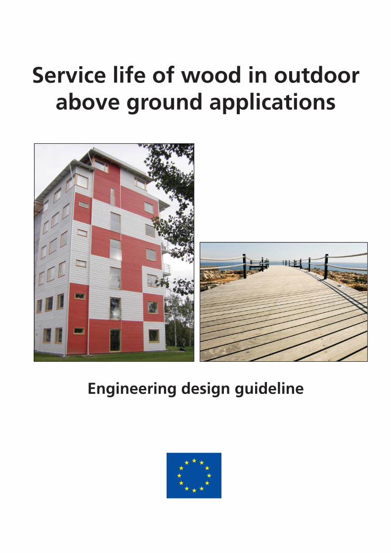
Service life of wood in outdoor above
ground applications
Engineering design guideline

Report TVBK‐3060 SP Report 2011:15 ISSN 0349‐4969 ISSN 0284‐5172 ISBN 978‐91‐979543‐0‐3 ISBN 978‐91‐86622‐46‐6
Lund University SP Technical Research Institute of Sweden Div. of Structural Engineering Box 857 Box 118 SE‐501 15 Borås SE‐221 00 Lund Sweden Sweden
Price 30 Euro Photos: SP Trätek and Panthermedia Translations of this guideline or parts of it need permission from Lund University. This English version must be referred to as the original source

1
Preface This is the first technical guideline in Europe for design of wooden constructions with respect to durability and service life. The guideline is focusing on constructions above ground, in particular on decking and cladding – two commodities where wood is abundantly used. The philosophy behind this guideline is similar to that of structural design and it shall be seen as the first attempt to develop a quantitative tool for use in practice. We believe that it will be continuously improved as it will be tested in practice by architects, specifiers and researchers, and that it will serve as a discussion document in the process of introducing performance-based engineering design for wood-based building components with respect to durability. The guideline has been developed within the European research project WoodExter (Service life and performance of exterior wood above ground). The project was initiated by the European Confederation of Woodworking Industries, CEI Bois, and their initiative Building with Wood, following a feasibility study on wood durability and service life in 2007. The financial support of WoodWisdom-Net (www.woodwisdom.net) and wood industry partnership
Building with Wood is gratefully acknowledged as well as the support from local industrial partners.
The WoodExter research partners are thanked for their cooperation and collaboration in this project.
Reinhold Steinmaurer Jöran Jermer Chairman of WoodExter Steering Committee WoodExter coordinator

2
WoodExter organization and support This guideline has been developed within the European project WoodExter (Service life and performance of exterior wood above ground) during 2008-2011. WoodExter has had the following R&D partners: SP Technical Research Institute of Sweden (co-ordinator) LTH - Lund University, Sweden BRE - Building Research Establishment, United Kingdom VTT, Finland FCBA, France HFA - Holzforschung Austria TUW – Technische Universität Wien, Austria NFLI – Norwegian Forest and Landscape Institute UGOE – Universität Göttingen, Germany UG – Universiteit Gent, Belgium Industrial partners were: CEI-Bois (major industrial partner) Swedish Wood Preservation Institute Södra Timber AB, Sweden Bergs Timber Bitus AB, Sweden Kebony ASA, Norway Fachverband der Holzindustrie Österreichs, Austria Synthesa GmbH, Austria Adler-Werk Lackfabrik, Austria
Author team The guideline has been written by the WoodExter partners and the following persons have directly contributed: Sven Thelandersson (editor), Tord Isaksson and Eva Frühwald, LTH Tomi Toratti and Hannu Viitanen, VTT Gerhard Grüll, HFA Jöran Jermer, SP Ed Suttie, BRE

3
Contents Summary 5 1. Introduction 7 2. Consequence class 9 3. Exposure index Isk 11 3.1 General 11 3.2 Basic exposure index Iso 1 3.3 Local conditions 14 3.4 Degree of sheltering and distance from ground 14 3.5 Detail design 15 3.5.1 General 15 3.5.2 Rating of details for decking 16 3.5.3 Ratings related to cladding 16 4. Design value IRd for resistance factor of the material 19 5. Calibration factor 21 6. Summary and conclusions 23 7. References 25 Annex. Application examples 27

4

5
Summary This engineering design guideline is intended for wood in outdoor above ground applications, i.e. use
class 3 according to EN 335. It is based on a prescribed limit state for onset of decay during a reference
service life of 30 years. Onset of decay is defined as a state of fungal attack according to rating 1 in EN
252. The approach is to determine the climate exposure as a function of geographical location, local
exposure conditions, sheltering, distance to ground and design of details. The exposure is then
compared with the material resistance defined in five classes and the design output is either OK or
NOT OK. The present version of the guideline covers applications for decking and cladding. The data
included in the guideline have partly been derived with the help of a dose-response model for decay,
which was used to derive relative measures of decay risk between different locations and between
different detail solutions. Other elements in the guideline have been estimated in a semi-subjective
manner based on expert opinions as well as experience from field testing. The guideline has been
verified by a number of reality checks of real buildings, which show that the output from the tool
agrees well with documented experience. The guideline has also been presented in a computerized
Excel format, which makes practical use more convenient. It is believed that many building
professionals will appreciate a tool within the area of wood durability which has an approach similar to
other design tasks in building projects. An advantage is that in applying the method the designer will go
through a check list where he/she becomes aware of the importance of appropriate design and
detailing solutions. In addition the user will have to consider the target service life as well as the
consequences of non-performance in the design of a construction.

6

7
1. Introduction This prototype guideline deals with wood in outdoor above ground applications, i.e. use class 3 according to EN 335 [1], focusing on cladding and decking, see Figure 1. The degradation mechanism considered is the risk for fungal decay. Two examples dealing with decking and cladding applications are presented in the Annex to this guideline. Background documentation for the guideline is presented in a separate publication [2].
Service life design is based on a clearly defined limit state, here corresponding to onset of decay,
during a reference service life assumed to be 30 years. Onset of decay is defined as a state of fungal
attack according to rating 1 in EN 252 [3]. Other types of limit states may be considered in the future,
such as a certain extent of decay or other reference service lives.
The design condition on the engineering level is formulated in the following way
RddSkSd III
(1)
where ISk is a characteristic exposure index, IRd is a design resistance index and d depends on
consequence class. The consequence class refers to the expected consequences if the limit state is
reached before the reference service life. If the condition in Eq. (1) is fulfilled, then the design is
accepted, otherwise it is not accepted.
The definitions of ISk and IRd are based on the following reference situations
Exposure situation: The exposure to outdoor temperature, relative humidity and rain of a horizontal member with no moisture traps, is used to define a basic exposure index depending on geographical location.
Material: Norway spruce (Picea abies) sapwood, uncoated, corresponds to IRd = 1,0
Consequence class 3 (most severe) corresponds to d = 1,0 Since the reference exposure is a favourable design condition for avoiding decay, the expsoure
normally gets worse when accounting for moisture traps and various design details. This is considered
by various exposure factors described in Section 3 below.

8
Figure 1. Design involving cladding and decking.
The design of a certain detail is made in the following steps:
1. Choose consequence class to determine d
2. Determine a base value IS0 for the exposure index depending on the geographical location
of interest
3. Find a correction factor for the exposure index to account for the local climate conditions
(meso-/micro climate). Factors of importance are orientation, overall geometry of the
structure, nature of the surroundings
4. Find appropriate correction factors for
a) Sheltering conditions
b) Distance from ground
c) Detailed design of the wood component considered
Steps 2-4 give a characteristic value ISk for the exposure index
5. Choose material to determine a design value IRd for the resistance index
6. Check performance by the condition
RdSkdSdIII
7. If non-performance, change inputs in some or all of steps 2, 3, 4 and 5.
Factors influencing exposure and resistance are described in the following sections.

9
2. Consequence class The consequence class depends on the severity of consequences in case of non-performance and is
described by the factor d as shown in Table 1.
Table 1. Safety factor d as a function of consequence class
Consequence class d
1 Small (e.g. cases where it may be acceptable to replace a limited number of elements in a structure if decay occurs)
0,8
2 Medium (e.g. cases where the expected consequences are of significant economic and practical nature)
0,9
3 High (e.g. wood elements in load-bearing structures where failure may imply risk for humans)
1

10

11
3. Exposure index ISk
3.1 General The exposure index Isk shall be conceived as a “characteristic (safe) value” accounting for uncertainties.
The exposure index is assumed to depend on
Geographical location determining global climate
Local climate conditions
The degree of sheltering
Distance from the ground
Detailed design of the wood component
Use and maintenance of coatings
The exposure index is determined by
aSssssSk cIkkkkI 04321 (2)
where
IS0 = basic exposure index depending on geographical location/global climate
ks1 = factor describing the effect of local climate conditions (meso-climate)
ks2 = factor describing the effect of sheltering
ks3 = factor describing the effect of distance from ground
ks4 = factor describing the effect of detailed design
ca = calibration factor to be determined by reality checks and expert input
The exposure index intends to describe the severity in terms of combined moisture and temperature
conditions favourable for development of decay fungi.
3.2 Basic exposure index IS0
The basic climate exposure index IS0 is a function of geographical location and describes the relative
climate effect on a horizontal board of spruce sapwood (exposed to rain but without moisture traps).
The exposure valid at one specific site, Helsinki, is chosen as reference, and IS0 = 1,0 at this site.
For other sites the (relative) base value of the exposure has been estimated with the help of the
performance model described in [2]. The performance model (in the form of dose-response
relationship) describes the combined effect of moisture content, temperature and the variation in
time of these parameters on the potential for decay fungi to germinate and grow. Values for a number
of European sites are shown in Figure 2. Table 2 gives these estimates on the European level evaluated
with performance models, taking into account the combined effect of moisture content and
temperature and where the moisture content includes the effect of rain. The macroclimate at different
sites is based on the software Meteonorm [4,5]. The underlying dose-response model is partly based
on Brischke et al [6]. The results have been partly verified against another model [7].

12
Table 2. Basic exposure index for different climate zones at altitudes lower than 500 m above sea level. For altitudes above 500 m, reduce factor by 0,3.
Climate Zones IS0 Description
Continental Europe 1,4 All Europe except Nordic, Atlantic and
Mediterranean zones
Nordic climate zone 1,0 Northern Europe
Atlantic climate zones:
South of latitude 50°
Latitude 50-55°
North of latitude 55°
2,0
1,7
1,4
Coastal regions, higher values in
southern parts, lower in northern parts
Mediterranean climate zone 1,5 Mediterranean regions south of the Alps

13
Figure 2. Relative climate exposure for sites in Europe. The results are based on reference [2].
The climate characterization for the whole Europe shown in Table 2 is basic and approximate. A more
detailed mapping on a national level should be made with the same methodology, which is presented
in the background document [2]. A more precise characterization for a given location can also be made
by using climate data from Meteonorm as input evaluating the dose according to the method
described in [2].

14
3.3 Local conditions This part describes the effect of meso-climate conditions and is a function of land topography,
adjacent buildings and distance from the sea. The local conditions are described in terms of four
classes as presented in Table 3. The factor ks1 is valid for wood facing the dominating wind direction,
since this case gives the most severe exposure. Adjustments for less exposed directions are not made,
because the design of e.g. cladding typically does not vary between different walls for the same
building.
Table 3. Definition of local conditions
Rating Description ks1
Light Local conditions have little impact on performance as the three
features all offer sheltering (i) land topography (ii) local buildings (iii)
>5 km from the sea (so no maritime effect).*
0,8
Medium Local conditions have some impact on performance as one of the
three features does not offer sheltering (i) land topography (ii) local
buildings (iii) >5 km from the sea (so no maritime effect).
1,0
Heavy Local conditions have an impact on performance as two of the three
features do not offer sheltering (i) land topography (ii) local buildings
(iii) >5 km from the sea (so no maritime effect).
1,2
Severe Local conditions have a significant impact on performance as the
three features do not offer sheltering (i) land topography (ii) local
buildings (iii) >5 km from the sea (so no maritime effect).**
1,4
* e.g. building is sheltered by hills and neighbouring buildings and is inland.
** e.g. building is on a flat plain, with no nearby buildings and less than 1 km from the sea.
3.4 Degree of sheltering and distance from ground The sheltering from eaves is described by a factor ks2, which is a function of the ratio of eave overhang
e relative to the position d of the detail under consideration, see Figure 3. The sheltering effect can be
used for both decking and cladding. Similarly, the effect of distance from ground is described by a
factor ks3, see Figure 3. Values for coefficients ks2 and ks3 are given in Tables 4 and 5.
Table 4. Effect of sheltering from eave overhang.
Sheltering: eave to detail position ratio e/d (see Figure 3) ks2
e>0,5d 0,7
e= 0,15d-0,5d 0,85
e<0,15 d (directly exposed to rain) 1,0

15
Table 5. Effect of distance from the ground.
Distance from ground ks3
> 300 mm 1,0
100 – 300 mm 1,5
< 100 mm 2,0
Figure 3. Illustration of effect of eave overhang and
definition of distance from ground.
3.5 Detail design
3.5.1 General
This part considers the microclimate conditions as influenced by the detailed design. Different details
are assumed to be allocated to 5 different ratings according to Table 6. This table describes the rating
in generic terms, and is illustrated below with separate interpretations for decking and cladding.
Eave length e
Wal
l hei
ght
d=P
osi
tio
n o
f
des
ign
det
ail
Dis
tan
ce
fro
m
gro
un
d
16
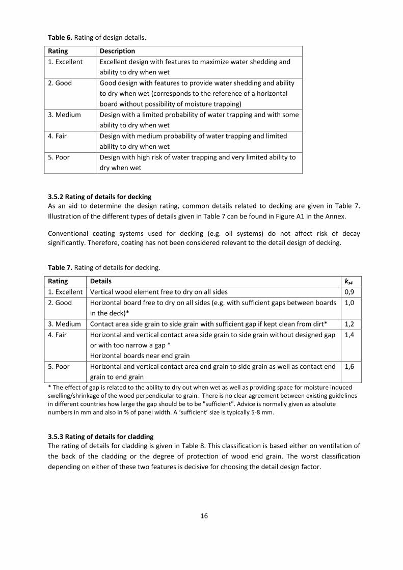
Table 6. Rating of design details.
Rating Description
1. Excellent Excellent design with features to maximize water shedding and
ability to dry when wet
2. Good Good design with features to provide water shedding and ability
to dry when wet (corresponds to the reference of a horizontal
board without possibility of moisture trapping)
3. Medium Design with a limited probability of water trapping and with some
ability to dry when wet
4. Fair Design with medium probability of water trapping and limited
ability to dry when wet
5. Poor Design with high risk of water trapping and very limited ability to
dry when wet
3.5.2 Rating of details for decking As an aid to determine the design rating, common details related to decking are given in Table 7.
Illustration of the different types of details given in Table 7 can be found in Figure A1 in the Annex.
Conventional coating systems used for decking (e.g. oil systems) do not affect risk of decay significantly. Therefore, coating has not been considered relevant to the detail design of decking.
Table 7. Rating of details for decking.
Rating Details ks4
1. Excellent Vertical wood element free to dry on all sides 0,9
2. Good Horizontal board free to dry on all sides (e.g. with sufficient gaps between boards
in the deck)*
1,0
3. Medium Contact area side grain to side grain with sufficient gap if kept clean from dirt* 1,2
4. Fair Horizontal and vertical contact area side grain to side grain without designed gap
or with too narrow a gap *
Horizontal boards near end grain
1,4
5. Poor Horizontal and vertical contact area end grain to side grain as well as contact end
grain to end grain
1,6
* The effect of gap is related to the ability to dry out when wet as well as providing space for moisture induced swelling/shrinkage of the wood perpendicular to grain. There is no clear agreement between existing guidelines in different countries how large the gap should be to be "sufficient". Advice is normally given as absolute numbers in mm and also in % of panel width. A ‘sufficient’ size is typically 5-8 mm.
3.5.3 Rating of details for cladding The rating of details for cladding is given in Table 8. This classification is based either on ventilation of
the back of the cladding or the degree of protection of wood end grain. The worst classification
depending on either of these two features is decisive for choosing the detail design factor.

17
fully ventilated limited ventilation not ventilated not ventilated with air space without air space
Figure 4. Categories of ventilation of the back of the cladding [8].
Ventilation of the back of the cladding depends on design of the exterior wall layers, and the four
categories included in Table 8 are shown and explained in Figure 4. Full ventilation is valid when
ventilation gaps are present at the bottom and the top of the cladding whereas the absence of
ventilation gaps reduces the ventilation of the back side. For non-ventilated cladding the presence of
an air space between the cladding and the outermost wall material (e.g. heat insulation) is decisive to
distinguish the two categories.
For the quality of end grain protection it is decisive if the end grain is protected by construction
elements or if it is open, whether or not a gap (> 1 cm) is constructed at the end grain of panels and
whether or not the end grain is sealed with low water permeability sealant.
Ventilation at the back of the cladding and end grain protection are the two major factors. Further
recommendations of best practice guidance documents should be respected but they usually have less
dominant impact on the risk of decay.
Coatings can have a positive effect to reduce the exposure of the wood provided that
The coating system is checked and maintained regularly
The coating system used is of the type that the risk for additional moisture trapping is limited,
i.e. it is sufficiently permeable for water vapour (sd-value ≤ 1 m)
Suitable board profiles with rounded edges (radius min 2,5 mm) are used for coated wood
parts
Coating application is carried out according to manufacturers’ specifications, early after machining the wood surface and shortly after installation of the cladding.

18
Table 8. Ratings of details for cladding (vertical wood members) depending on ventilation (a) or end grain protection (b). The worst rating of (a) and (b) determines the overall rating.
Rating a) Ventilation b) End grain protection Uncoated Coated
ks4 ks4
1. Excellent fully ventilated with gap and sealed or
end grain covered
0,8 0,5
2. Good limited ventilation with gap unsealed 0,9 0,6
3. Medium not ventilated with air
space
1,1 0,9
4. Fair without gap but sealed 1,3 1,1
5. Poor not ventilated without air
space
without gap and unsealed 1,5 1,5

19
4. Design value IRd for resistance factor of the material The design resistance index IRd for selected wood materials is determined on the basis of resistance
class according to Table 9. This is a simplified first step for a material resistance classification based on
a balanced expert judgment of moisture dynamics and durability class. The resistance class term is
based on a combination of durability class data according to EN 350-2 [9], test data, practical
experience of treatability and permeability for wood species as well as experience from use in practice.
Biological durability is the key factor determining performance for wood in different use classes. The
robust laboratory and field test methods that exist make it possible to assign a durability rating to
timber linked to the intended use class according to EN 335 [1], assuming a worst case scenario. Other
factors, see Section 3 above, determine the likelihood of the worst case scenario occurring in practice.
The natural durability of wood is classified into durability classes as described in EN 350-1 [9] and
presented as durability classes for heartwood of timber species in EN 350-2 [9]. Durability class is a
classification on five levels from non-durable to very durable. This is based on decades of data from
ground contact field trials for use class 4. The natural durability for a wood species can vary widely.
Table 9. Resistance rating of selected wood materials and corresponding design resistance index IRd.
Material resistance class
Examples of wood materials* IRd
A Heartwood of very durable hardwoods, e.g. afzelia, robinia (durability class 1) Preservative-treated sapwood, industrially processed to meet requirements of use class 3
10,0
B Heartwood of durable wood species e.g. sweet chestnut and western red cedar (durability class 2)
5,0
C Heartwood of moderately and slightly durable wood species e.g. douglas fir, larch and Scots pine (durability classes 3 and 4)
2,0
D Slightly durable wood species having low water permeability (e.g. Norway spruce)
1,0
E Sapwood of all wood species (and where sapwood content in the untreated product is high)
0,7
* For the majority of wood materials there is variability in material resistance. The material resistance classification should
defer to local knowledge based on experience of performance of cladding and decking and where this is not available field test data and then laboratory test data. It is possible that a classification with different design resistance indices may need to be adopted for specific regions or countries, based on practical experience e.g. from the use of a material in that region.
For out of ground contact (e.g. exterior wood cladding) the challenge is to translate durability class from use class 4 to use class 3. In EN 350-1 [9] the term “markedly different” is used to describe the additional benefits of low permeability on the performance of wood out of ground contact. Expert advice is recommended for assigning the material resistance class for wood materials such as: Preservative treated wood is often a combination of mixed treated heartwood and sapwood. The
treated sapwood should be thoroughly treated and enhanced to durability class 1. The heartwood is
more resistant to treatment and the enhancement of the heartwood can be considered to be slightly
higher than the natural durability class of the heartwood for the species (EN 350-2). Therefore, for
preservative treated decking it may be more sensible to take a mid-point between the resistance class
of the treated sapwood and the treated heartwood. E.g. for pine heartwood treated (resistance class
20
C) and pine sapwood treated (resistance class A) the overall batch of preservative treated wood should
then be classified as resistance class B.
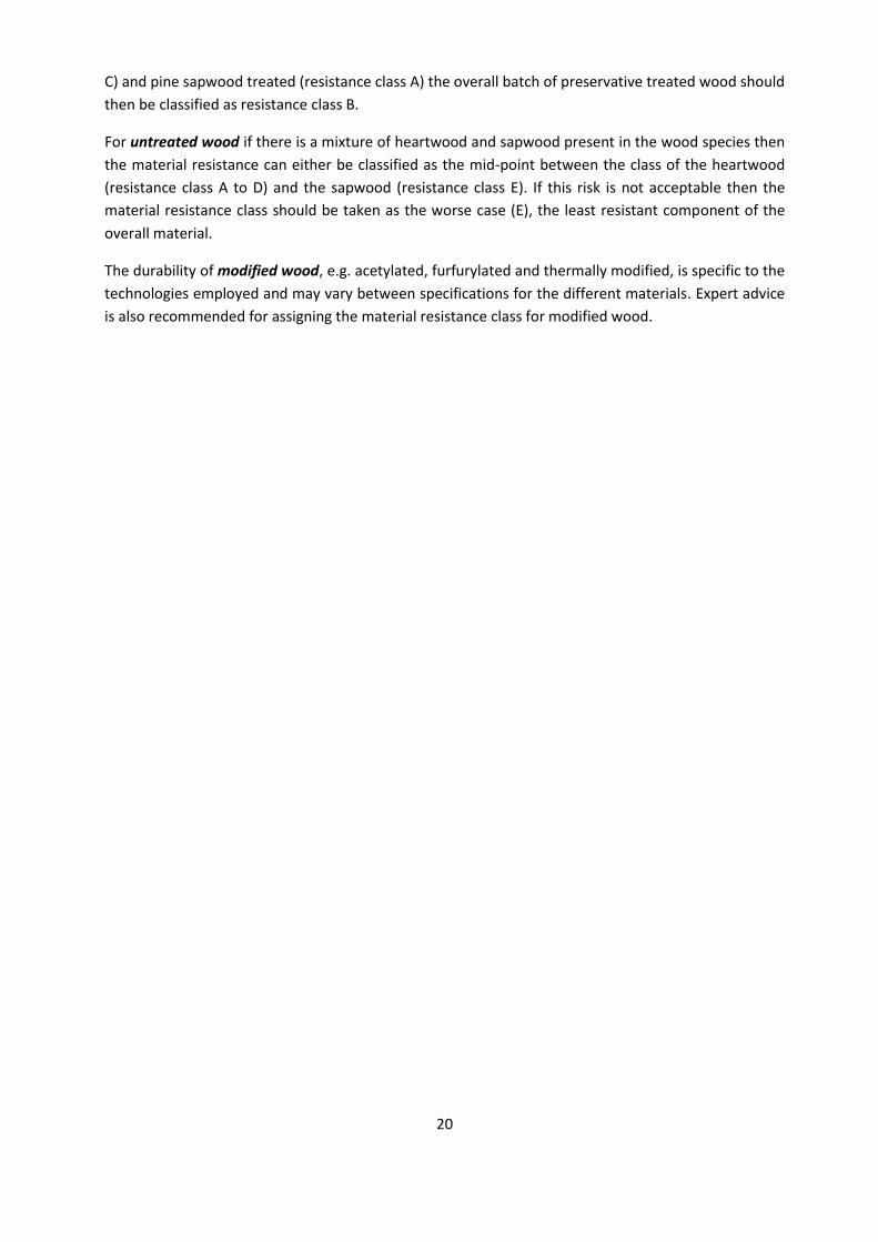
For untreated wood if there is a mixture of heartwood and sapwood present in the wood species then
the material resistance can either be classified as the mid-point between the class of the heartwood
(resistance class A to D) and the sapwood (resistance class E). If this risk is not acceptable then the
material resistance class should be taken as the worse case (E), the least resistant component of the
overall material.
The durability of modified wood, e.g. acetylated, furfurylated and thermally modified, is specific to the
technologies employed and may vary between specifications for the different materials. Expert advice
is also recommended for assigning the material resistance class for modified wood.

21
5. Calibration factor All elements in the design system are expressed in relative terms. The calibration factor has been
determined to ca =1,0, which means that the system will give reasonable results in accordance with
generally accepted experience. This is documented in [2] by verifications of the guideline against a
number of reality checks with good results. There are however always uncertainties in this kind of
design given the high variability for both exposure and resistance. The user may increase the safety of
the design by choosing a higher value for the calibration factor.

22

23
6. Summary and conclusions Examples illustrating the application of the guideline are given in the Annex. A software tool, based on
Excel, is available to facilitate application of the guideline [10].
Background documentation is presented in [2] on how the values have been determined from
experimental data and physical models. Where necessary, input based on experience and expert
opinions has been used for some of the elements in the design guideline. The guideline can be seen as
a first attempt to formulate a quantitative type of tool in this field, and it could be continuously
improved in the future when new research results and data become available.
It is not possible to quantify all the factors in this design method on a scientific basis. But the
characteristic exposure index for the reference situation has been estimated by using time series of
climate data at different geographical locations together with performance models for onset of decay.
Attempts have been made to make a relevant assessment of variability to achieve appropriate safety
margins.
The system gives the designer a method to consider climate conditions at the actual geographical site
and also to some extent local exposure conditions. A very simplified way to account for the effect of
coatings on exposure has also been introduced.
One advantage with the system is that the user is encouraged to think about the consequences of
violation of the limit state. Another advantage is that in applying the method the designers will go
through a check list where they will become aware of the importance of appropriate detailing
solutions. Even if the factors describing the effects of detailing, contact zones, coating systems and
maintenance are difficult to quantify in a reliable way the use of the method will generally lead to
better solutions.
Many users have limited understanding of the concept of durability by design. Direct descriptions of so
called best practice solutions are quite difficult to use because the designer does not understand what
happens if the solution is modified, which is most often necessary.
The resistance class describing effect of wood material selection is estimated by relative comparison
between the decay resistance of different materials, supported by subjective expert opinions. An
important background are the test results presented by Brischke [6].
The design system as a whole has also been tested with good results in a number of "reality checks" from real buildings, to see if the output from the design method agrees with known experience and results from practice investigated in a separate part of project WoodExter. These reality checks are reported in reference [2].

24
25
7. References [1] EN 335 (1992). Durability of wood and wood-based products - Definition of hazard classes of biological attack.
[2] Thelandersson, S, Isaksson, T, Suttie, E, Frühwald, E, Toratti, T, Grüll, G, Viitanen, H, Jermer, J (2011).
Background document for "Service life of wood in outdoor above ground applications - Engineering design
guideline". Report TVBK-3061. Div. of Structural Engineering, Lund University, Sweden.
[3] EN 252 (1989). Wood preservatives. Field test methods for determining the relative protective effectiveness
in ground contact.
[4] Meteonorm. Global Meteorological Database for Engineers, Planners and Education.
http://www.meteonorm.com/ METEOTEST.
[5] Remund, J and S, Kunz (1995). METEONORM – a comprehensive meteorological database and planning tool
for system design. In Proceedings of 13th Solar Energy Photovoltaic Conference and Exhibition, Nice. Commission
of the European Communities (CEC). [Volume 1].
[6] Brischke, C (2007) Investigation of decay influencing factors for service life prediction of exposed wooden
components. Dissertation, Univ. of Hamburg.
[7] Viitanen, H, Toratti T, Makkonen, L, Peuhkari, R, Ojanen, T, Ruokolainen, L, Räisänen, J (2010). Towards
modelling of decay risk of wooden materials. Eur. J. Wood Prod. (2010), 68: 303-313.
[8] Schober, K P, Auer, C, Dolezal, F, Gamerith, H, Grüll, G, Höfler K et al (2010): Fassaden aus Holz. 1. Aufl.,
proHolz Austria, Vienna.
[9] EN 350 (1994). Durability of wood and wood-based products - Natural durability of solid wood. Part 1: Guide
to the principles of testing and classification of the natural durability of wood. Part 2: Guide to natural durability
and treatability of selected wood species of importance in Europe.
[10] Excel tool, see www.kstr.lth.se.

26

27
Annex: Application examples
Example 1: Design of decking
Based on the design guideline the decking shown in Figure A1 will be checked. Details A-E are
identified and evaluated.
Figure A1. Decking with design details. Courtesy: Timber Decking Association, UK.
Consequence class 2 is assumed for details A, C, D and E. d=0,9
Consequence class 1 is assumed for decking boards (can be easily replaced) d=0,8
Exposure index
Location Berlin ISo=1,26 (Figure. 2)
Local conditions, rating medium ks1 = 1,0 (Table 3)
Sheltering: Exposed to rain ks2 = 1,0 (Table 4)
Coating: No coating
The different details are described in Table A1.
Calibration factor ca = 1,0
Horizontal
Spacing
Contact area
(horizontal, side-side grain)
Contact area
(vertical, side-side grain)
Vertical
Contact area
(vertical,
end-side grain)
gap
A
B
C
D
E

28
Table A1. Calculation of exposure index for the decking details shown in Figure A1.
Detail ca ks1ks2 Iso Distance
from
ground, mm
ks3
Table 4
Detail rating
Table 7
ks4 Isk d Isd=
d Isk
A 1,26 200 1,5 1 0,9 1,70 0,9 1,53
B 1,26 >300 1,0 2 1,0 1,26 0.8 1,01
C 1,26 >300 1,0 4 1,4 1,76 0,9 1,59
D 1,26 >300 1,0 4 1,4 1,76 0,9 1,59
E 1,26 >300 1,0 5 1,6 2,01 0,9 1,81
Resistance index (for all details)
Material: larch (heartwood, resistance class C) IRd =2,0
Verification of performance
The design criterion
RdSdII
is therefore fulfilled for the details considered in the decking. The margin is however narrow especially
for detail E. It is also very important that the material in the decking does not contain sapwood. If that
cannot be guaranteed the value IRd = 1,5 should be taken (average between class C and D). In that case
the design is not acceptable.
Example 2: Design of cladding
Two details are identified to demonstrate the guideline for cladding, see Figure A2. It is assumed that
the coating is correctly maintained on the building and fulfills the coating requirements specified in
section 3.5.3.
Consequence class 2 d=0,9
Exposure index
Location Växjö, Sweden IS0=1,22 (calculated from Meteonorm)
Local conditions, medium rating ks1 = 1,0
Detail A (cover boarding with rib flanges)
Sheltering: Eave length 0,5m, detail position 6 m, e=0,083 d<0,15 d ks2=1,0 (Table 4)
Distance from ground: >300 mm ks3=1,0 (Table 5)
Boards with designed fully ventilated cavity behind boards, end grain with gap unsealed and coating
correctly maintained (rating good) ks4 = 0,6 (Table 8)

29
This gives (Eq. 2 with ca = 1,0)
Isk = 1,0 1,0 1,0 0,6 1,22 1,0= 0,73 and
Isd= dIsk = 0,9 0,73 = 0,66
Figure A2. Cladding with design details.
Detail B (casing for window, end to side grain)
Sheltering:
Eave length 0,5m, detail position 5 m, e=0,1 d ks2=1,0 (Table 4)
Distance from ground: >300 mm ks3=1,0 (Table 5 )
End grain protection: Vertical end to side grain, without gap but sealed, coating with correct
maintenance ks4=0,9 (Table 8, rating medium).
This gives (Eq. 2 with ca = 1,0)
Isk = 1,0 1,0 1,0 0,9 1,22 1,0= 1,10 and
Isd= dIsk = 0,9 1,1 = 0,99
Resistance index (for all details)
Material: spruce. From Table 9: IRd = 1,0
Thus it is safe to use spruce for the general cladding area, but the detail for the casing around the
window has a low safety margin.
A
B
Service life of wood in outdoor above ground applicationsEngineering design guideline
This engineering design guideline is intended for wood in outdoor above ground applications, i.e. use class 3 according to EN 335. It is based on a prescribed limit state for onset of decay during a reference service life of 30 years. Onset of decay is defi ned as a state of fungal attack according to rating 1 in EN 252. The approach is to determine the climate exposure as a function of geographical location, local exposure conditions, sheltering, distance to ground and design of details. The exposure is then compared with the material resistance defi ned in fi ve classes and the design output is either OK or NOT OK. The present version of the guideline covers appli-cations for decking and cladding. The data included in the guideline have partly been derived with the help of a dose-response model for decay, which was used to derive relative measures of decay risk between different locations and between different detail solutions. Other elements in the guideline have been estimated in a semi-subjective manner based on expert opinions as well as experience from fi eld testing. The guideline has been verifi ed by a number of reality checks of real buildings, which show that the output from the tool agrees well with documented experience. The guideline has also been presented in a computerized Excel format, which makes practical use convenient. It is believed that many building professio-nals will appreciate a tool within the area of wood durability which has an approach similar to other design tasks in building projects. An advantage is that in applying the method the designer will go through a check list where he/she becomes aware of the importance of appropriate detailing solutions. In addition the user will have to consider the target service life as well as the consequences of non-performance in the design of a construction.