SERVICE INSTRUCTIONS 8302 TM Diaphragm Pump - … · TM SERVICE INSTRUCTIONS Diaphragm Pump 8302...
13
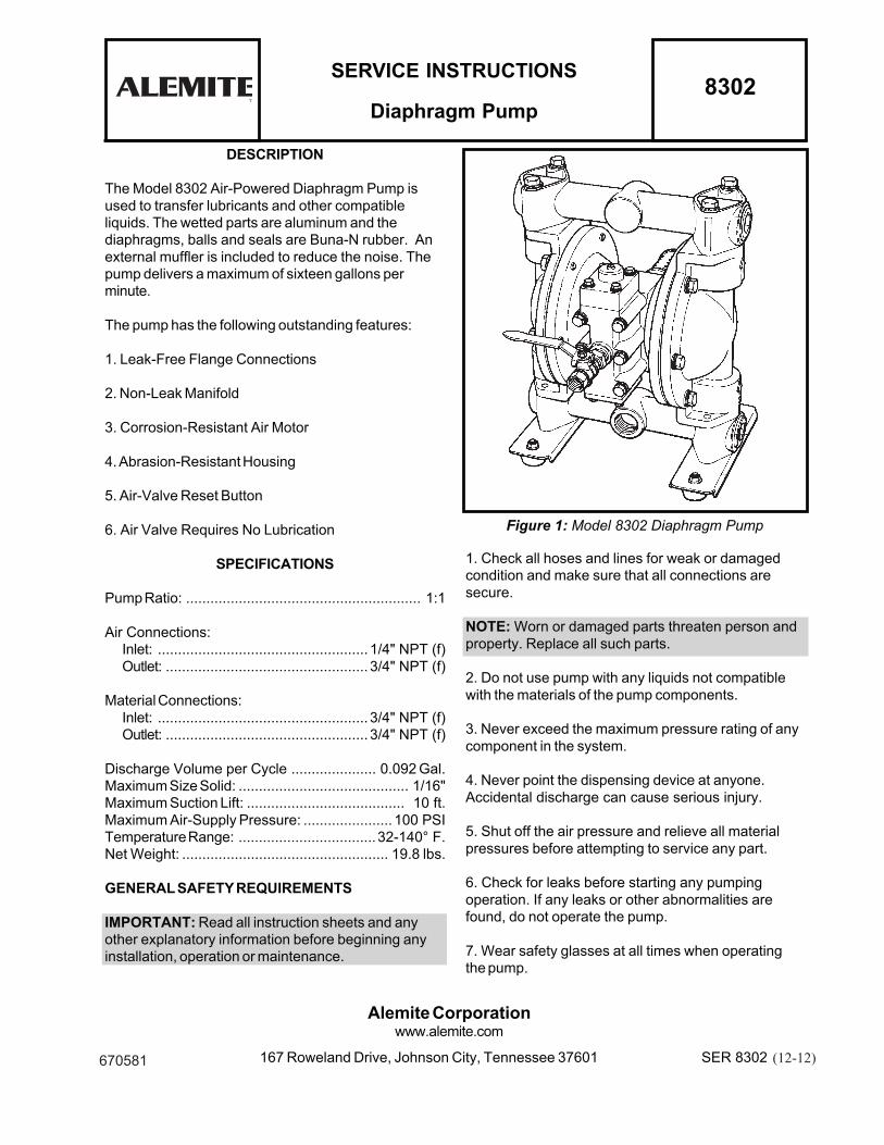
TM SERVICE INSTRUCTIONS Diaphragm Pump 8302 Figure 1: Model 8302 Diaphragm Pump 1. Check all hoses and lines for weak or damaged condition and make sure that all connections are secure. NOTE: Worn or damaged parts threaten person and property. Replace all such parts. 2. Do not use pump with any liquids not compatible with the materials of the pump components. 3. Never exceed the maximum pressure rating of any component in the system. 4. Never point the dispensing device at anyone. Accidental discharge can cause serious injury. 5. Shut off the air pressure and relieve all material pressures before attempting to service any part. 6. Check for leaks before starting any pumping operation. If any leaks or other abnormalities are found, do not operate the pump. 7. Wear safety glasses at all times when operating the pump. DESCRIPTION The Model 8302 Air-Powered Diaphragm Pump is used to transfer lubricants and other compatible liquids. The wetted parts are aluminum and the diaphragms, balls and seals are Buna-N rubber. An external muffler is included to reduce the noise. The pump delivers a maximum of sixteen gallons per minute. The pump has the following outstanding features: 1. Leak-Free Flange Connections 2. Non-Leak Manifold 3. Corrosion-Resistant Air Motor 4. Abrasion-Resistant Housing 5. Air-Valve Reset Button 6. Air Valve Requires No Lubrication SPECIFICATIONS Pump Ratio: .......................................................... 1:1 Air Connections: Inlet: .................................................... 1/4" NPT (f) Outlet: .................................................. 3/4" NPT (f) Material Connections: Inlet: .................................................... 3/4" NPT (f) Outlet: .................................................. 3/4" NPT (f) Discharge Volume per Cycle ..................... 0.092 Gal. Maximum Size Solid: .......................................... 1/16" Maximum Suction Lift: ....................................... 10 ft. Maximum Air-Supply Pressure: ...................... 100 PSI Temperature Range: .................................. 32-140° F. Net Weight: ................................................... 19.8 lbs. GENERAL SAFETY REQUIREMENTS IMPORTANT: Read all instruction sheets and any other explanatory information before beginning any installation, operation or maintenance. Alemite Corporation www.alemite.com 167 Roweland Drive, Johnson City, Tennessee 37601 SER 8302 ( 2 670581 (12-12)
Transcript of SERVICE INSTRUCTIONS 8302 TM Diaphragm Pump - … · TM SERVICE INSTRUCTIONS Diaphragm Pump 8302...
TM
SERVICE INSTRUCTIONS
Diaphragm Pump8302
Figure 1: Model 8302 Diaphragm Pump
1. Check all hoses and lines for weak or damaged
condition and make sure that all connections are
secure.
NOTE: Worn or damaged parts threaten person and
property. Replace all such parts.
2. Do not use pump with any liquids not compatible
with the materials of the pump components.
3. Never exceed the maximum pressure rating of any
component in the system.
4. Never point the dispensing device at anyone.
Accidental discharge can cause serious injury.
5. Shut off the air pressure and relieve all material
pressures before attempting to service any part.
6. Check for leaks before starting any pumping
operation. If any leaks or other abnormalities are
found, do not operate the pump.
7. Wear safety glasses at all times when operating
the pump.
DESCRIPTION
The Model 8302 Air-Powered Diaphragm Pump is
used to transfer lubricants and other compatible
liquids. The wetted parts are aluminum and the
diaphragms, balls and seals are Buna-N rubber. An
external muffler is included to reduce the noise. The
pump delivers a maximum of sixteen gallons per
minute.
The pump has the following outstanding features:
1. Leak-Free Flange Connections
2. Non-Leak Manifold
3. Corrosion-Resistant Air Motor
4. Abrasion-Resistant Housing
5. Air-Valve Reset Button
6. Air Valve Requires No Lubrication
SPECIFICATIONS
Pump Ratio: .......................................................... 1:1
Air Connections:
Inlet: .................................................... 1/4" NPT (f)
Outlet: .................................................. 3/4" NPT (f)
Material Connections:
Inlet: .................................................... 3/4" NPT (f)
Outlet: .................................................. 3/4" NPT (f)
Discharge Volume per Cycle ..................... 0.092 Gal.
Maximum Size Solid: .......................................... 1/16"
Maximum Suction Lift: ....................................... 10 ft.
Maximum Air-Supply Pressure: ...................... 100 PSI
Temperature Range: ..................................32-140° F.
Net Weight: ................................................... 19.8 lbs.
GENERAL SAFETY REQUIREMENTS
IMPORTANT: Read all instruction sheets and any
other explanatory information before beginning any
installation, operation or maintenance.
Alemite Corporationwww.alemite.com
167 Roweland Drive, Johnson City, Tennessee 37601 SER 8302 ( 2670581 (12-12)
SER 8302
▼
▲
▼
▼
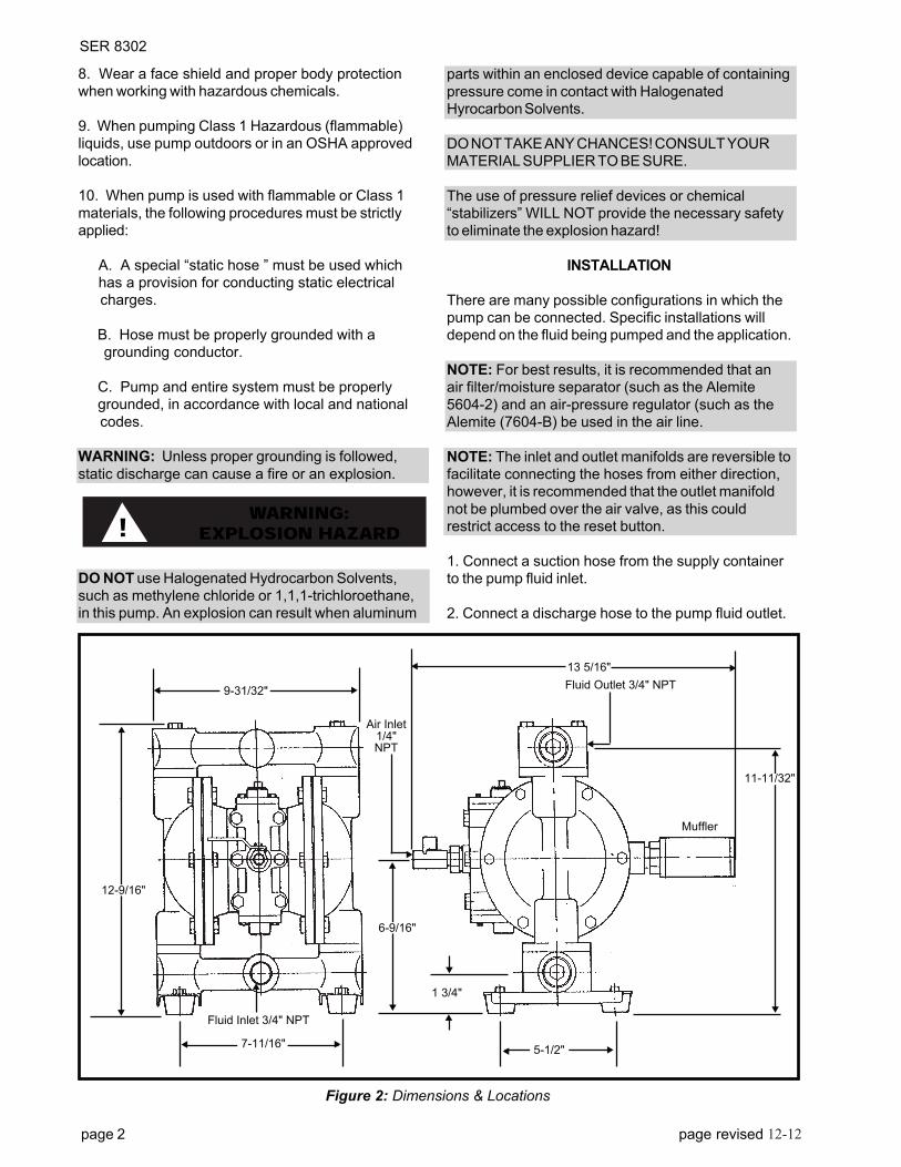
▼9-31/32"
7-11/16"
12-9/16"
6-9/16"
5-1/2" ▼
▼
▼
▼
▼
▲
▲
▲
▼
Air Inlet1/4"NPT
▼
▼
1 3/4"▲
Figure 2: Dimensions & Locations
13 5/16"
11-11/32"
Fluid Inlet 3/4" NPT
Fluid Outlet 3/4" NPT
▼
8. Wear a face shield and proper body protection
when working with hazardous chemicals.
9. When pumping Class 1 Hazardous (flammable)
liquids, use pump outdoors or in an OSHA approved
location.
10. When pump is used with flammable or Class 1
materials, the following procedures must be strictly
applied:
A. A special “static hose ” must be used which
has a provision for conducting static electrical
charges.
B. Hose must be properly grounded with a
grounding conductor.
C. Pump and entire system must be properly
grounded, in accordance with local and national
codes.
WARNING: Unless proper grounding is followed,
static discharge can cause a fire or an explosion.
DO NOT use Halogenated Hydrocarbon Solvents,
such as methylene chloride or 1,1,1-trichloroethane,
in this pump. An explosion can result when aluminum
! WARNING:EXPLOSION HAZARD
parts within an enclosed device capable of containing
pressure come in contact with Halogenated
Hyrocarbon Solvents.
DO NOT TAKE ANY CHANCES! CONSULT YOUR
MATERIAL SUPPLIER TO BE SURE.
The use of pressure relief devices or chemical
“stabilizers” WILL NOT provide the necessary safety
to eliminate the explosion hazard!
INSTALLATION
There are many possible configurations in which the
pump can be connected. Specific installations will
depend on the fluid being pumped and the application.
NOTE: For best results, it is recommended that an
air filter/moisture separator (such as the Alemite
5604-2) and an air-pressure regulator (such as the
Alemite (7604-B) be used in the air line.
NOTE: The inlet and outlet manifolds are reversible to
facilitate connecting the hoses from either direction,
however, it is recommended that the outlet manifold
not be plumbed over the air valve, as this could
restrict access to the reset button.
1. Connect a suction hose from the supply container
to the pump fluid inlet.
2. Connect a discharge hose to the pump fluid outlet.
▼
Muffler
page 2 page revised 6-0312-12
SER 8302
page revised 6-03 page 3
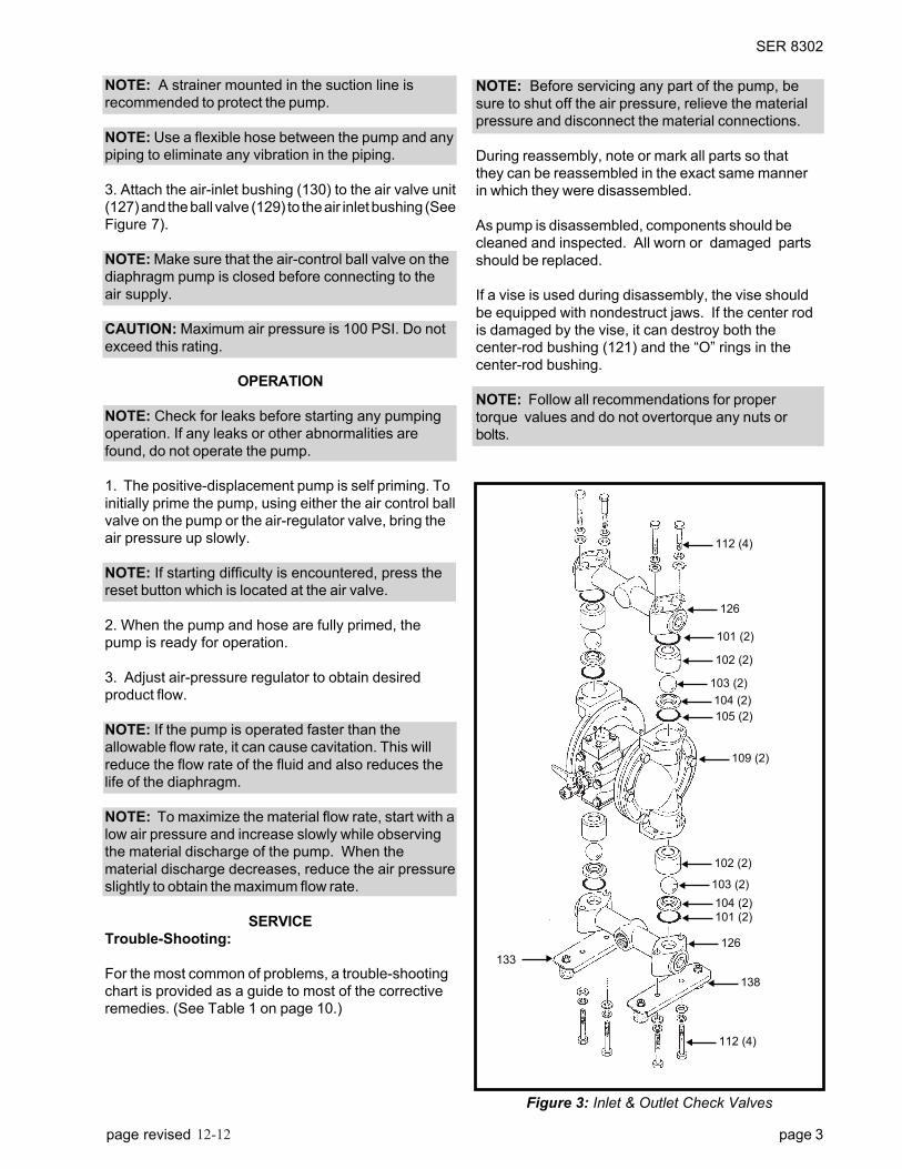
Figure 3: Inlet & Outlet Check Valves
▼
112 (4)
▼
126
▼
101 (2)
▼
102 (2)
▼
103 (2)
▼
104 (2)
▼
105 (2)
▼
109 (2)
▼
102 (2)
▼
103 (2)
▼
104 (2)
▼
101 (2)
▼
126
▼
138
▼
112 (4)
▼133
NOTE: Before servicing any part of the pump, be
sure to shut off the air pressure, relieve the material
pressure and disconnect the material connections.
During reassembly, note or mark all parts so that
they can be reassembled in the exact same manner
in which they were disassembled.
As pump is disassembled, components should be
cleaned and inspected. All worn or damaged parts
should be replaced.
If a vise is used during disassembly, the vise should
be equipped with nondestruct jaws. If the center rod
is damaged by the vise, it can destroy both the
center-rod bushing (121) and the “O” rings in the
center-rod bushing.
NOTE: Follow all recommendations for proper
torque values and do not overtorque any nuts or
bolts.
NOTE: A strainer mounted in the suction line is
recommended to protect the pump.
NOTE: Use a flexible hose between the pump and any
piping to eliminate any vibration in the piping.
3. Attach the air-inlet bushing (130) to the air valve unit
(127) and the ball valve (129) to the air inlet bushing (See
Figure 7).
NOTE: Make sure that the air-control ball valve on the
diaphragm pump is closed before connecting to the
air supply.
CAUTION: Maximum air pressure is 100 PSI. Do not
exceed this rating.
OPERATION
NOTE: Check for leaks before starting any pumping
operation. If any leaks or other abnormalities are
found, do not operate the pump.
1. The positive-displacement pump is self priming. To
initially prime the pump, using either the air control ball
valve on the pump or the air-regulator valve, bring the
air pressure up slowly.
NOTE: If starting difficulty is encountered, press the
reset button which is located at the air valve.
2. When the pump and hose are fully primed, the
pump is ready for operation.
3. Adjust air-pressure regulator to obtain desired
product flow.
NOTE: If the pump is operated faster than the
allowable flow rate, it can cause cavitation. This will
reduce the flow rate of the fluid and also reduces the
life of the diaphragm.
NOTE: To maximize the material flow rate, start with a
low air pressure and increase slowly while observing
the material discharge of the pump. When the
material discharge decreases, reduce the air pressure
slightly to obtain the maximum flow rate.
SERVICE
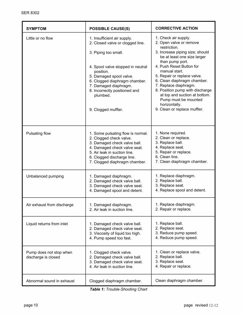
Trouble-Shooting:
For the most common of problems, a trouble-shooting
chart is provided as a guide to most of the corrective
remedies. (See Table 1 on page 10.)
12-12
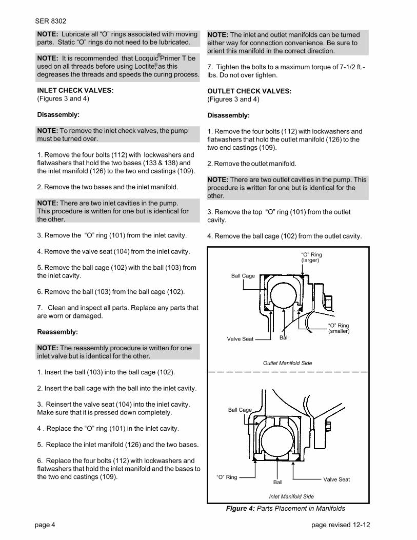
Figure 4: Parts Placement in Manifolds
“O” Ring(smaller)
▲
Ball
▲▲
Valve Seat
▼
“O” Ring(larger)
▼
Ball Cage
Outlet Manifold Side
▲
▼
Ball
Inlet Manifold Side
▼
Ball Cage
▲
“O” Ring Valve Seat
SER 8302
NOTE: Lubricate all “O” rings associated with moving
parts. Static “O” rings do not need to be lubricated.
NOTE: It is recommended that Locquic Primer T be
used on all threads before using Loctite, as this
degreases the threads and speeds the curing process.
INLET CHECK VALVES:
(Figures 3 and 4)
Disassembly:
NOTE: To remove the inlet check valves, the pump
must be turned over.
1. Remove the four bolts (112) with lockwashers and
flatwashers that hold the two bases (133 & 138) and
the inlet manifold (126) to the two end castings (109).
2. Remove the two bases and the inlet manifold.
NOTE: There are two inlet cavities in the pump.
This procedure is written for one but is identical for
the other.
3. Remove the “O” ring (101) from the inlet cavity.
4. Remove the valve seat (104) from the inlet cavity.
5. Remove the ball cage (102) with the ball (103) from
the inlet cavity.
6. Remove the ball (103) from the ball cage (102).
7. Clean and inspect all parts. Replace any parts that
are worn or damaged.
Reassembly:
NOTE: The reassembly procedure is written for one
inlet valve but is identical for the other.
1. Insert the ball (103) into the ball cage (102).
2. Insert the ball cage with the ball into the inlet cavity.
3. Reinsert the valve seat (104) into the inlet cavity.
Make sure that it is pressed down completely.
4 . Replace the “O” ring (101) in the inlet cavity.
5. Replace the inlet manifold (126) and the two bases.
6. Replace the four bolts (112) with lockwashers and
flatwashers that hold the inlet manifold and the bases to
the two end castings (109).
page 4 page revised
NOTE: The inlet and outlet manifolds can be turned
either way for connection convenience. Be sure to
orient this manifold in the correct direction.
7. Tighten the bolts to a maximum torque of 7-1/2 ft.-
lbs. Do not over tighten.
OUTLET CHECK VALVES:
(Figures 3 and 4)
Disassembly:
1. Remove the four bolts (112) with lockwashers and
flatwashers that hold the outlet manifold (126) to the
two end castings (109).
2. Remove the outlet manifold.
NOTE: There are two outlet cavities in the pump. This
procedure is written for one but is identical for the
other.
3. Remove the top “O” ring (101) from the outlet
cavity.
4. Remove the ball cage (102) from the outlet cavity.
®
®
SER 8302
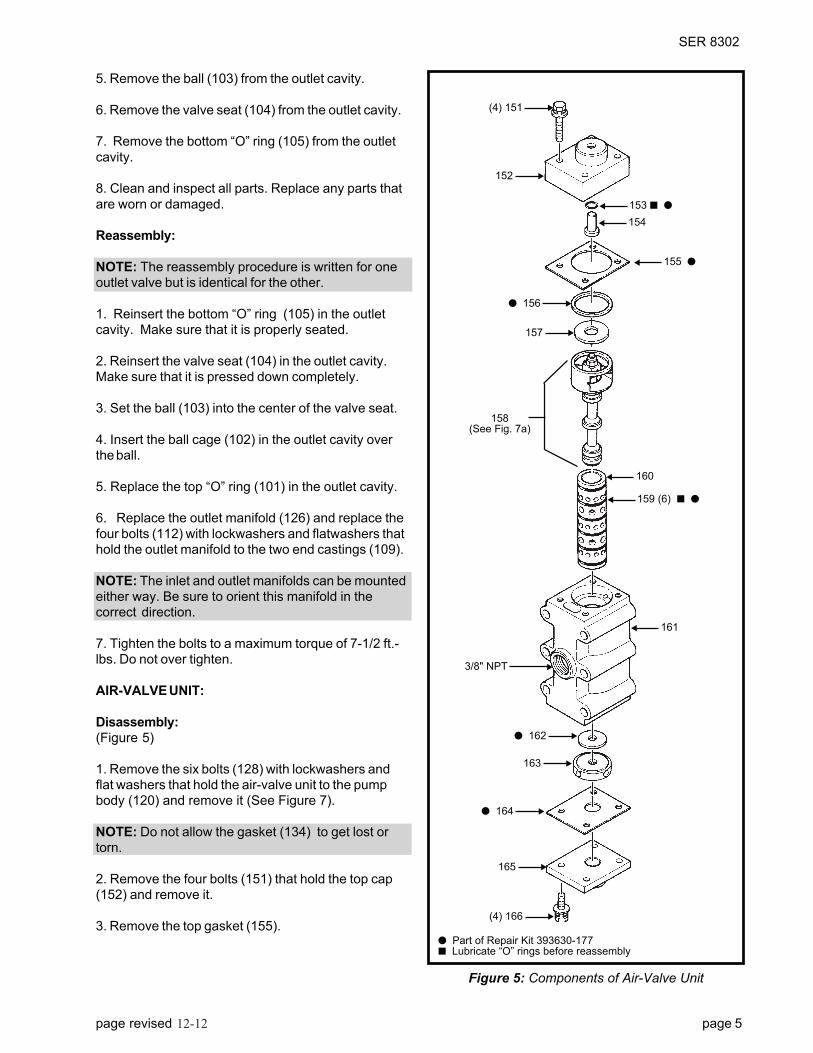
▼153 ■ ●
▼
154
▼
155 ●
▼
160
▼
159 (6) ■ ●
▼
161
▼(4) 166
▼165
▼● 164
▼ 163
▼ ● 162
▼157
▼ ● 156
▼152
▼(4) 151
▼3/8" NPT
158(See Fig. 7a)
page revised 6-03 page 5
5. Remove the ball (103) from the outlet cavity.
6. Remove the valve seat (104) from the outlet cavity.
7. Remove the bottom “O” ring (105) from the outlet
cavity.
8. Clean and inspect all parts. Replace any parts that
are worn or damaged.
Reassembly:
NOTE: The reassembly procedure is written for one
outlet valve but is identical for the other.
1. Reinsert the bottom “O” ring (105) in the outlet
cavity. Make sure that it is properly seated.
2. Reinsert the valve seat (104) in the outlet cavity.
Make sure that it is pressed down completely.
3. Set the ball (103) into the center of the valve seat.
4. Insert the ball cage (102) in the outlet cavity over
the ball.
5. Replace the top “O” ring (101) in the outlet cavity.
6. Replace the outlet manifold (126) and replace the
four bolts (112) with lockwashers and flatwashers that
hold the outlet manifold to the two end castings (109).
NOTE: The inlet and outlet manifolds can be mounted
either way. Be sure to orient this manifold in the
correct direction.
7. Tighten the bolts to a maximum torque of 7-1/2 ft.-
lbs. Do not over tighten.
AIR-VALVE UNIT:
Disassembly:
(Figure 5)
1. Remove the six bolts (128) with lockwashers and
flat washers that hold the air-valve unit to the pump
body (120) and remove it (See Figure 7).
NOTE: Do not allow the gasket (134) to get lost or
torn.
2. Remove the four bolts (151) that hold the top cap
(152) and remove it.
3. Remove the top gasket (155).● Part of Repair Kit 393630-177■ Lubricate “O” rings before reassembly
Figure 5: Components of Air-Valve Unit
12-12
SER 8302
page 6 page revised 6-03
4. Remove the reset button (154) and the “O” ring
(153) from the top cap (152). Replace the “O” ring
with the one in the kit.
5. Remove the rubber packing (156) and the metal
washer (157).
6. Remove the four bolts (166) that hold the bottom
cap (165) and remove it with its gasket (164).
7. Remove the lantern ring (163) and the air-valve
cushion (162) from the air-valve body (161).
8. Push the Spool-Valve Assembly (158) out by hand
from the bottom of the air-valve body.
9. Check the seal rings (173) on the spool assembly
for any damage. If any defects are found, replace the
seal rings, cushion and nut from kit 393630-179.
10. Remove the sleeve (160) from the air-valve body.
11. Check the six “O” rings (159) on the sleeve for
any damage. If any is found, replace the ”O” rings.
Reassembly:
(Figure 5)
1. Push the sleeve (160) with “O” rings (159) into the
air-valve body and center the sleeve in the air-valve
body (161).
NOTE: To ease installation, apply grease to the “O”
rings.
2. Push the Spool-Valve Assembly (158) with seal
rings (173) into the sleeve from the top of the air-valve
body.
CAUTION: Be careful not to damage the seal rings.
3. Place the metal washer (157) and the rubber
packing (156) on the Spool-Valve Assembly.
4. Place the top gasket (155) on the air-valve body.
5. Place the reset button (154) with “O” ring (153)
into the top cap (152).
6. Reattach the top cap onto the air-valve body and
secure with the four bolts (151). Do Not Overtighten.
7. Place the lantern ring (163) and the air-valve
cushion (162) into the air valve body (161).
8. Replace the bottom cap (165) and its gasket (164)
and secure with the four bolts (166). Do Not
Overtighten.
9. Place the air-valve gasket (134) behind the air-
valve unit (127) and secure the air-valve unit to the
pump body (120) using the six bolts (128) (Figure 7).
NOTE: Make sure that the reset button is facing up.
10. Tighten the bolts by a criss-cross method to
prevent any unusual strain on the aluminum air-valve.
Torque to 20 ft.-lbs. Do Not Overtighten.
ENTIRE PUMP:
Disassembly: (Figures 6 and 7)
1. Remove the muffler (135) from the pump body
(120).
2. Remove the air valve unit (127) and its gasket (134)
from the pump body (120) by removing six hex-head
bolts (128).
NOTE: Do not allow the gasket (134) to get torn or
lost.
NOTE: It is not necessary to remove the ball valve
(129) or the bushing (130) if the air valve is not to be
serviced.
3. Remove the inlet and outlet manifolds (126) by
removing the four bolts (112) for each one.
NOTE: The bases (133 and 138) will come off with
the inlet manifold.
4. Remove the six bolts (113) on one end casting
(109) and remove the end casting.
5. Repeat step 4 for the other end casting.
6. Remove the hex nut (110) on one end of the center
rod (124). Remove the cone-disk spring washer
(111).
7. Remove one washer (108), one centerdisk (107),
the rubber diaphragm (106), a second centerdisk
(107) and a second washer (108) and the diaphragm
cushion (125) from the center rod (124).
8. Repeat steps 6 and 7 for the same parts on the
other side of the center rod.
9. Using a five-millimeter Allen wrench, remove the
four flat-head bolts (123) with four lock washers that
hold the air-chamber disk (114).
12-12
SER 8302
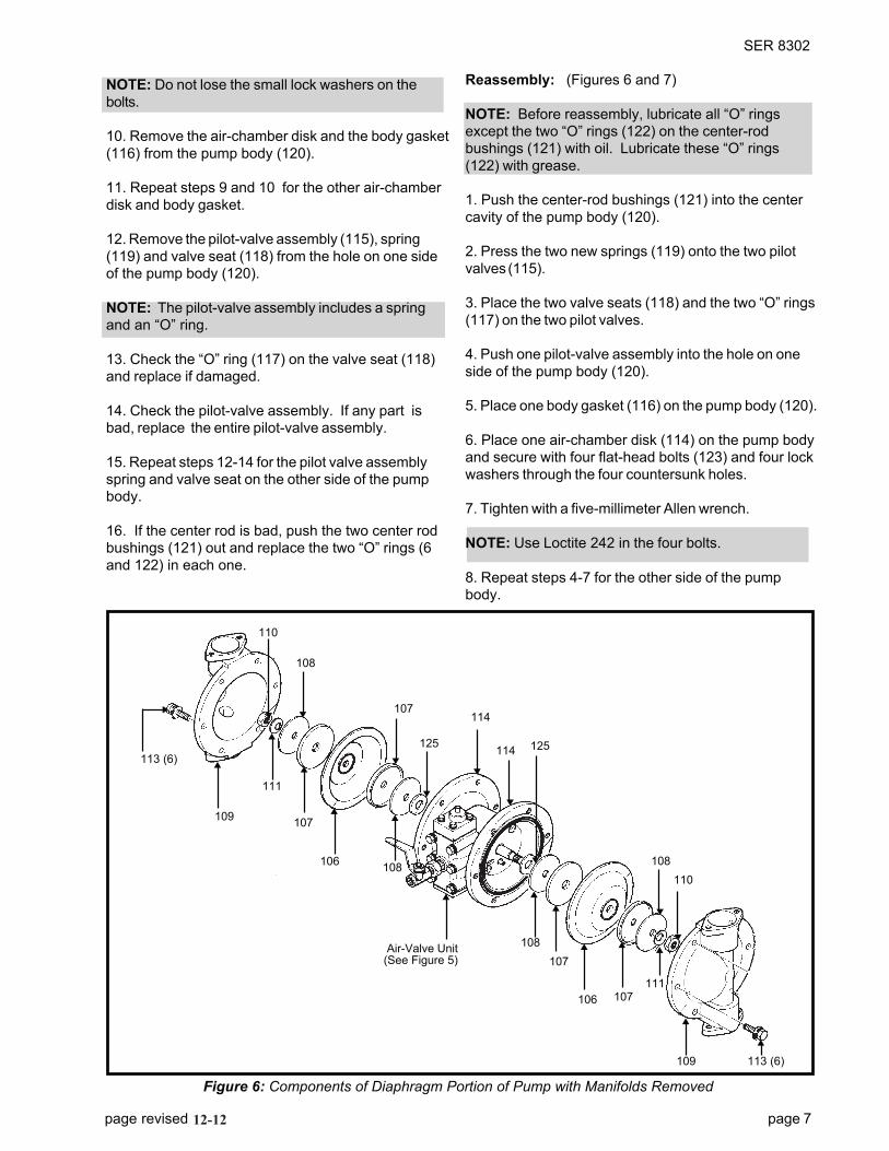
Figure 6: Components of Diaphragm Portion of Pump with Manifolds Removed
▼
125
▼
113 (6) ▼
109
▼
111
▼
107
▼
106
▼
108
Air-Valve Unit(See Figure 5)
▼ ▼
108
▼
107
▼
106
▼
107
▼
111
▼
▼
▼
108
110
▼
▼
114
▼
114
▼
125
▼
107▼
108
▼
109 113 (6)
page revised 6-03 page 7
NOTE: Do not lose the small lock washers on the
bolts.
10. Remove the air-chamber disk and the body gasket
(116) from the pump body (120).
11. Repeat steps 9 and 10 for the other air-chamber
disk and body gasket.
12. Remove the pilot-valve assembly (115), spring
(119) and valve seat (118) from the hole on one side
of the pump body (120).
NOTE: The pilot-valve assembly includes a spring
and an “O” ring.
13. Check the “O” ring (117) on the valve seat (118)
and replace if damaged.
14. Check the pilot-valve assembly. If any part is
bad, replace the entire pilot-valve assembly.
15. Repeat steps 12-14 for the pilot valve assembly
spring and valve seat on the other side of the pump
body.
16. If the center rod is bad, push the two center rod
bushings (121) out and replace the two “O” rings (6
and 122) in each one.
Reassembly: (Figures 6 and 7)
NOTE: Before reassembly, lubricate all “O” rings
except the two “O” rings (122) on the center-rod
bushings (121) with oil. Lubricate these “O” rings
(122) with grease.
1. Push the center-rod bushings (121) into the center
cavity of the pump body (120).
2. Press the two new springs (119) onto the two pilot
valves (115).
3. Place the two valve seats (118) and the two “O” rings
(117) on the two pilot valves.
4. Push one pilot-valve assembly into the hole on one
side of the pump body (120).
5. Place one body gasket (116) on the pump body (120).
6. Place one air-chamber disk (114) on the pump body
and secure with four flat-head bolts (123) and four lock
washers through the four countersunk holes.
7. Tighten with a five-millimeter Allen wrench.
NOTE: Use Loctite 242 n the four bolts.
8. Repeat steps 4-7 for the other side of the pump
body.
110
12-12
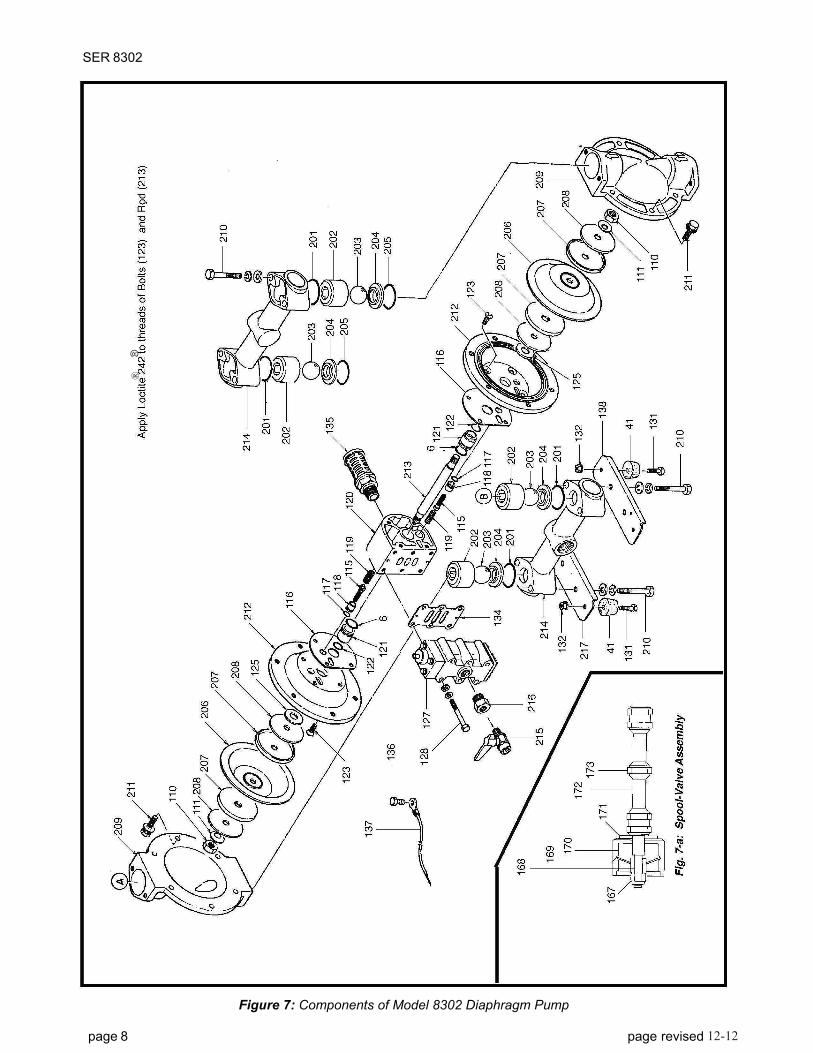
Figure 7: Components of Model 8302 Diaphragm Pump
SER 8302
page 8 page revised 6-03
®®
12-12
page revised 6-03 page 9
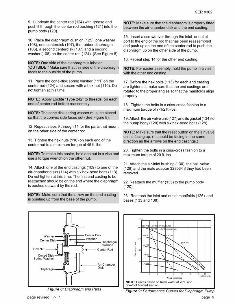
Figure 9: Performance Curves for Diaphragm PumpFigure 8: Diaphragm and Parts
▼Center Disk
▼Coned DiskSpring Washer
▼Diaphragm
▼ Center Disk
▼ Washer
▼
DiaphragmCushion
▼
▼ Air-ChamberDisk
Center Rod▼Hex Nut
Rubber DiaphragmMeter Feet
Dis
char
ge
Hea
d
(Air Supply Pressure)
(Air Consumption)
Water DischargeGallon/Min.
Liter/Min.
100PSI
5CFM
10CFM
15CFM
80PSI
60PSI
40PSI
20PSI
70
60
50
40
30
20
10
0
200
150
100
50
02 4 6 8 10 12 14 16
0 10 20 30 40 50 60NOTE: Curves based on fresh water at 70°F andone-foot flooded suction.
Dis
char
ge
Hea
d
Water Discharge
SER 8302
NOTE: Make sure that the diaphragm is properly fitted
between the air-chamber disk and the end casting.
15. Insert a screwdriver through the inlet or outlet
port to the end of the rod that has been reassembled
and push up on the end of the center rod to push the
diaphragm up on the other side of the pump.
16. Repeat step 14 for the other end casting.
NOTE: For easier assembly, hold the pump in a vise
with the other end casting.
17. Before the hex bolts (113) for each end casting
are tightened, make sure that the end castings are
rotated to the proper angles so that the manifolds align
properly.
18. Tighten the bolts in a criss-cross fashion to a
maximum torque of 7-1/2 ft.-lbs.
19. Attach the air valve unit (127) and its gasket (134) to
the pump body (120) with six hex-head bolts (128).
NOTE: Make sure that the reset button on the air valve
unit is facing up. (It should be facing in the same
direction as the arrows on the end castings.)
20. Tighten the bolts in a criss-cross fashion to a
maximum torque of 20 ft. lbs.
21. Attach the air-inlet bushing (130), the ball valve
(129) and the male adapter 328034 if they had been
removed.
22. Reattach the muffler (135) to the pump body
(120).
23. Reattach the inlet and outlet manifolds (126) and
bases (133 and 138).
9. Lubricate the center rod (124) with grease and
push it through the center rod bushing (121) into the
pump body (120).
10. Place the diaphragm cushion (125), one washer
(108), one centerdisk (107), the rubber diaphragm
(106), a second centerdisk (107) and a second
washer (108) on the center rod (124). (See Figure 8).
NOTE: One side of the diaphragm is labeled
“OUTSIDE.” Make sure that this side of the diaphragm
faces to the outside of the pump.
11. Place the cone-disk spring washer (111) on the
center rod (124) and secure with a hex nut (110). Do
not tighten at this time.
NOTE: Apply Loctite “Type 242” to threads on each
end of center rod before reassembly.
NOTE: The cone disk spring washer must be placed
so that the convex side faces out (See Figure 8).
12. Repeat steps 9 through 11 for the parts that mount
on the other side of the center rod.
13. Tighten the hex nuts (110) on each end of the
center rod to a maximum torque of 45 ft. lbs.
NOTE: To make this easier, hold one nut in a vise and
use a torque wrench on the other nut.
14. Attach one of the end castings (109) to one of the
air-chamber disks (114) with six hex-head bolts (113).
Do not tighten at this time. The first end casting to be
reattached should be on the end where the diaphragm
is pushed outward by the rod.
NOTE: Make sure that the arrow on the end casting
is pointing up from the base of the pump.
▼Washer
12-12
SER 8302
SYMPTOM
Little or no flow
Pulsating flow
Unbalanced pumping
Air exhaust from discharge
Liquid returns from inlet
Pump does not stop when
discharge is closed
Abnormal sound in exhaust
POSSIBLE CAUSE(S)
1. Insufficient air supply.
2. Closed valve or clogged line.
3. Piping too small.
4. Spool valve stopped in neutral
position.
5. Damaged spool valve.
6. Clogged diaphragm chamber.
7. Damaged diaphragm.
8. Incorrectly positioned and
plumbed.
9. Clogged muffler.
1. Some pulsating flow is normal.
2. Clogged check valve.
3. Damaged check valve ball.
4. Damaged check valve seat.
5. Air leak in suction line.
6. Clogged discharge line.
7. Clogged diaphragm chamber.
1. Damaged diaphragm.
2. Damaged check valve ball.
3. Damaged check valve seat.
4. Damaged spool and detent.
1. Damaged diaphragm.
2. Air leak in suction line.
1. Damaged check valve ball.
2. Damaged check valve seat.
3. Viscosity of liquid too high.
4. Pump speed too fast.
1. Clogged check valve.
2. Damaged check valve ball.
3. Damaged check valve seat.
4. Air leak in suction line.
Clogged diaphragm chamber.
CORRECTIVE ACTION
1. Check air supply.
2. Open valve or remove
restriction.
3. Increase piping size; should
be at least one size larger
than pump port.
4. Push Reset Button for
manual start.
5. Repair or replace valve.
6. Clean diaphragm chamber.
7. Replace diaphragm.
8. Position pump with discharge
at top and suction at bottom.
Pump must be mounted
horizontally.
9. Clean or replace muffler.
1. None required.
2. Clean or replace.
3. Replace ball.
4. Replace seat.
5. Repair or replace.
6. Clean line.
7. Clean diaphragm chamber.
1. Replace diaphragm.
2. Replace ball.
3. Replace seat.
4. Replace spool and detent.
1. Replace diaphragm.
2. Repair or replace.
1. Replace ball.
2. Replace seat.
3. Reduce pump speed.
4. Reduce pump speed.
1. Clean or replace valve.
2. Replace ball.
3. Replace seat.
4. Repair or replace.
Clean diaphragm chamber.
Table 1: Trouble-Shooting Chart
page 10 page revised 6-0312-12
SER 8302
page revised 6-03 page 11
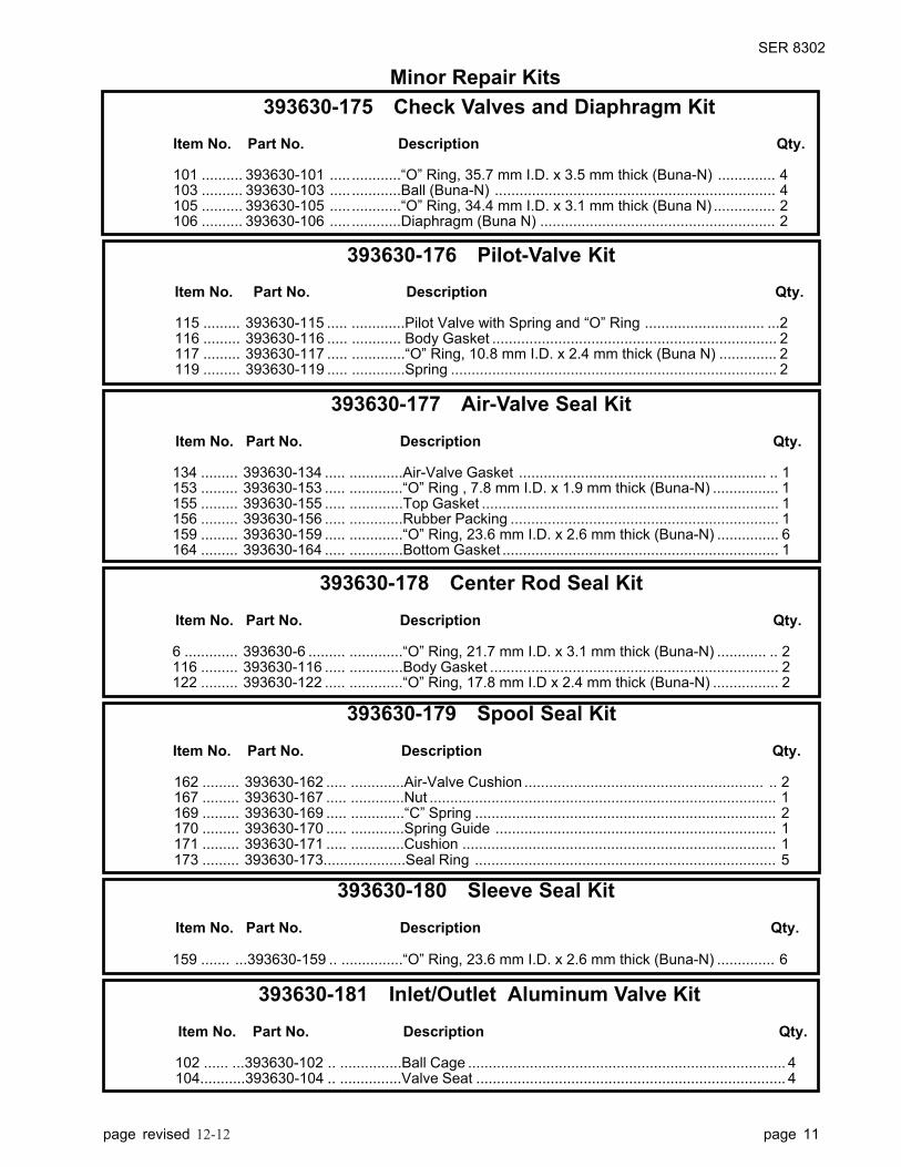
393630-176 Pilot-Valve Kit
Item No. Part No. Description Qty.
115 ......... 393630-115 ..... .............Pilot Valve with Spring and “O” Ring ............................. ...2116 ......... 393630-116 ..... ............ Body Gasket ..................................................................... 2117 ......... 393630-117 ..... .............“O” Ring, 10.8 mm I.D. x 2.4 mm thick (Buna N) .............. 2119 ......... 393630-119 ..... .............Spring ............................................................................... 2
393630-175 Check Valves and Diaphragm Kit
Item No. Part No. Description Qty.
101 .......... 393630-101 ..... ............“O” Ring, 35.7 mm I.D. x 3.5 mm thick (Buna-N) .............. 4103 .......... 393630-103 ..... ............Ball (Buna-N) .................................................................... 4105 .......... 393630-105 ..... ............“O” Ring, 34.4 mm I.D. x 3.1 mm thick (Buna N) ............... 2106 .......... 393630-106 ..... ............Diaphragm (Buna N) ......................................................... 2
393630-177 Air-Valve Seal Kit
Item No. Part No. Description Qty.
134 ......... 393630-134 ..... .............Air-Valve Gasket ............................................................ .. 1153 ......... 393630-153 ..... .............“O” Ring , 7.8 mm I.D. x 1.9 mm thick (Buna-N) ................ 1155 ......... 393630-155 ..... .............Top Gasket ........................................................................ 1156 ......... 393630-156 ..... .............Rubber Packing ................................................................. 1159 ......... 393630-159 ..... .............“O” Ring, 23.6 mm I.D. x 2.6 mm thick (Buna-N) ............... 6164 ......... 393630-164 ..... .............Bottom Gasket ................................................................... 1
393630-178 Center Rod Seal Kit
Item No. Part No. Description Qty.
6 ............. 393630-6 ......... .............“O” Ring, 21.7 mm I.D. x 3.1 mm thick (Buna-N) ............ .. 2116 ......... 393630-116 ..... .............Body Gasket ...................................................................... 2122 ......... 393630-122 ..... .............“O” Ring, 17.8 mm I.D x 2.4 mm thick (Buna-N) ................ 2
393630-180 Sleeve Seal Kit
Item No. Part No. Description Qty.
159 ....... ...393630-159 .. ...............“O” Ring, 23.6 mm I.D. x 2.6 mm thick (Buna-N) .............. 6
393630-181 Inlet/Outlet Aluminum Valve Kit
Item No. Part No. Description Qty.
102 ...... ...393630-102 .. ...............Ball Cage ............................................................................. 4 104...........393630-104 .. ...............Valve Seat ........................................................................... 4
393630-179 Spool Seal Kit
Item No. Part No. Description Qty.
162 ......... 393630-162 ..... .............Air-Valve Cushion .......................................................... .. 2167 ......... 393630-167 ..... .............Nut .................................................................................... 1169 ......... 393630-169 ..... .............“C” Spring ......................................................................... 2170 ......... 393630-170 ..... .............Spring Guide .................................................................... 1171 ......... 393630-171 ..... .............Cushion ............................................................................ 1173 ......... 393630-173....................Seal Ring ......................................................................... 5
Minor Repair Kits
12-12

PARTS LIST – Model 8302 Diaphragm Pump
Item No. Part No. Description Qty.
6 ............. 393630-6 ......... “O” Ring, 21.7 mm I.D. x 3.1 mm thick (Buna-N) ........................ 2
41 ........... 393630-41 ....... Rubber Foot ................................................................................. 4
101 ......... 393630-101 ..... “O” Ring, 35.7 mm I.D. x 3.5 mm thick (Buna-N) ........................ 4
102 ......... 393630-102 ..... Ball Cage ...................................................................................... 4
103 ......... 393630-103 ..... Ball (Buna-N) ............................................................................... 4
104 ......... 393630-104 ..... Valve Seat .................................................................................... 4
105 ......... 393630-105 ..... “O” Ring, 34.4 mm I.D. x 3.1 mm thick (Buna-N) ........................ 2
106 ......... 393630-106 ..... Diaphragm (Buna-N) .................................................................... 2
107 ......... 393630-107 ..... Center Disk .................................................................................. 4
108 ......... 393630-108 ..... Washer, 2-1/2" O.D. ..................................................................... 4
109 ......... 393630-109 ..... End Casting .................................................................................. 2
110 ......... 393630-110 ..... Hex Nut ........................................................................................ 2
111 ......... 393630-111 ..... Coned Disk Spring Washer .......................................................... 2
112 ......... 393630-112 ..... Hex-Head Bolt .............................................................................. 8
113 ......... 393630-113 ..... Hex-Head Bolt ............................................................................ 12
114 ......... 393630-114 ..... Air-Chamber Disk ........................................................................ 2
115 ......... 393630-115 ..... Pilot Valve with spring and “O” ring ............................................. 2
116 ......... 393630-116 ..... Body Gasket ................................................................................ 2
117 ......... 393630-117 ..... “O” Ring, 10.8 mm I.D. x 2.4 mm thick (Buna-N) ........................ 2
118 ......... 393630-118 ..... Valve Seat .................................................................................... 2
119 ......... 393630-119 ..... Spring ........................................................................................... 2
120 ......... 393630-120 ..... Pump Body ................................................................................... 1
121 ......... 393630-121 ..... Center-Rod Bushing ..................................................................... 2
122 ......... 393630-122 ..... “O” Ring, 17.8 mm I.D. x 2.4 mm thick (Buna-N) ........................ 2
123 ......... 393630-123 ..... Flat-Head Bolt with Lockwasher .................................................. 8
124 ......... 393630-124 ..... Center Rod ................................................................................... 1
125 ......... 393630-125 ..... Diaphragm Cushion (Buna-N) ...................................................... 2
126 ......... 393630-126 ..... Manifold ........................................................................................ 2
127 ......... 393630-127 ..... Air-Valve Unit ............................................................................... 1
128 ......... 393630-128 ..... Hex-Head Bolt, 7 x 75 x 1.25 mm ................................................ 6
129 ......... 393630-129 ..... Ball Valve ..................................................................................... 1
130 ......... 393630-130 ..... Air-Inlet Bushing ........................................................................... 1
131 ......... 393630-131 ..... Hex-Head Bolt .............................................................................. 4
132 ......... 393630-132 ..... Lock Nut ....................................................................................... 4
133 ......... 393630-133 ..... Base ............................................................................................. 1
134 ......... 393630-134 ..... Air-Valve Gasket .......................................................................... 1
135 ......... 393630-135 ..... Muffler .......................................................................................... 1
136 ......... 393630-136 ..... Hex-Head Bolt .............................................................................. 1
137 ......... 393630-137 ..... Ground Strap ................................................................................ 1
138 ......... 393630-138 ..... Base ............................................................................................. 1
● Repair-Kit Part
❋ See Separate Parts List
✚ Not available as a separate purchased part
● ✚
● ✚
● ✚
● ✚
● ✚
● ✚
✚
● ✚
✚
✚
✚
✚
✚
✚
● ✚
● ✚
● ✚
● ✚
✚
● ✚
✚
❋ ✚
✚
✚
✚
✚
✚
●
✚
✚
✚
SER 8302
page 12 page revised 6-0312-12
SER 8302
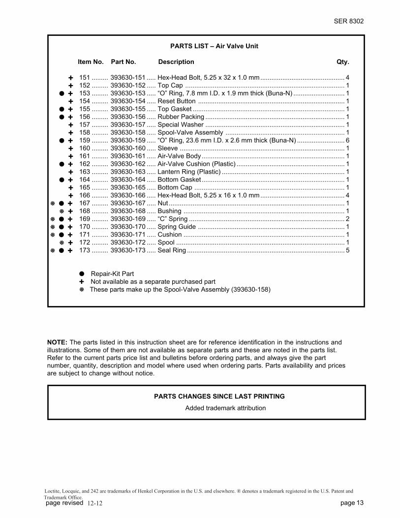
PARTS LIST – Air Valve Unit
Item No. Part No. Description Qty.
151 ......... 393630-151 ..... Hex-Head Bolt, 5.25 x 32 x 1.0 mm.............................................. 4
152 ......... 393630-152 ..... Top Cap ....................................................................................... 1
153 ......... 393630-153 ..... “O” Ring, 7.8 mm I.D. x 1.9 mm thick (Buna-N) ............................ 1
154 ......... 393630-154 ..... Reset Button ................................................................................ 1
155 ......... 393630-155 ..... Top Gasket ................................................................................... 1
156 ......... 393630-156 ..... Rubber Packing ............................................................................ 1
157 ......... 393630-157 ..... Special Washer ............................................................................ 1
158 ......... 393630-158 ..... Spool-Valve Assembly ................................................................. 1
159 ......... 393630-159 ..... “O” Ring, 23.6 mm I.D. x 2.6 mm thick (Buna-N) .......................... 6
160 ......... 393630-160 ..... Sleeve .......................................................................................... 1
161 ......... 393630-161 ..... Air-Valve Body.............................................................................. 1
162 ......... 393630-162 ..... Air-Valve Cushion (Plastic) ........................................................... 1
163 ......... 393630-163 ..... Lantern Ring (Plastic) ................................................................... 1
164 ......... 393630-164 ..... Bottom Gasket .............................................................................. 1
165 ......... 393630-165 ..... Bottom Cap .................................................................................. 1
166 ......... 393630-166 ..... Hex-Head Bolt, 5.25 x 16 x 1.0 mm.............................................. 4
167 ......... 393630-167 ..... Nut ................................................................................................ 1
168 ......... 393630-168 ..... Bushing ........................................................................................ 1
169 ......... 393630-169 ..... “C” Spring ..................................................................................... 2
170 ......... 393630-170 ..... Spring Guide ................................................................................ 1
171 ......... 393630-171 ..... Cushion ........................................................................................ 1
172 ......... 393630-172 ..... Spool ............................................................................................ 1
173 ......... 393630-173 ..... Seal Ring ...................................................................................... 5
● Repair-Kit Part
✚ Not available as a separate purchased part
❋ These parts make up the Spool-Valve Assembly (393630-158)
NOTE: The parts listed in this instruction sheet are for reference identification in the instructions and
illustrations. Some of them are not available as separate parts and these are noted in the parts list.
Refer to the current parts price list and bulletins before ordering parts, and always give the part
number, quantity, description and model where used when ordering parts. Parts availability and prices
are subject to change without notice.
PARTS CHANGES SINCE LAST PRINTING
✚
✚
● ✚
✚
● ✚
● ✚
✚
✚
● ✚
✚
✚
● ✚
✚
● ✚
✚
✚
❋ ● ✚
❋ ✚
❋ ● ✚
❋ ● ✚
❋ ● ✚
❋ ✚
❋ ● ✚
page revised page 13
Loctite, Locquic, and 242 are trademarks of Henkel Corporation in the U.S. and elsewhere. ® denotes a trademark registered in the U.S. Patent and
Trademark Office.
12-12