
Service - ApplianceAssistant.comapplianceassistant.com/ServiceManuals/16026312... · Ice and Water...
71
Ice and Water Bottom Mount Refrigerators This Base Manual covers general information Refer to individual Technical Sheet for information on specific models This manual includes, but is not limited to the following: Amana AFI2237AE* AFI2538AE* AFD25BCZX* AFD25WBZX* Service This manual is to be used by qualified appliance technicians only. Maytag does not assume any responsibility for property damage or personal injury for improper service procedures done by an unqualified person. 16026312 February 2006 Maytag MFI2067AE* MFI2266AE* MFI2568AE*
Transcript of Service - ApplianceAssistant.comapplianceassistant.com/ServiceManuals/16026312... · Ice and Water...

Ice and WaterBottom MountRefrigerators
This Base Manual covers general informationRefer to individual Technical Sheetfor information on specific models
This manual includes, but isnot limited to the following:
Amana
AFI2237AE*AFI2538AE*AFD25BCZX*AFD25WBZX*
ServiceThis manual is to be used by qualified appliancetechnicians only. Maytag does not assume anyresponsibility for property damage or personalinjury for improper service procedures done byan unqualified person.
16026312February 2006
Maytag
MFI2067AE*MFI2266AE*MFI2568AE*

2 16026312 ©2006 Maytag Services
Important Notices for Servicers and ConsumersMaytag will not be responsible for personal injury or property damage from improper service procedures. Pride andworkmanship go into every product to provide our customers with quality products. It is possible, however, thatduring its lifetime a product may require service. Products should be serviced only by a qualified service technicianwho is familiar with the safety procedures required in the repair and who is equipped with the proper tools, parts,testing instruments and the appropriate service information. IT IS THE TECHNICIANS RESPONSIBILITY TOREVIEW ALL APPROPRIATE SERVICE INFORMATION BEFORE BEGINNING REPAIRS.
! WARNINGTo avoid risk of severe personal injury or death, disconnect power before working/servicing on appliance to avoidelectrical shock.
To locate an authorized servicer, please consult your telephone book or the dealer from whom you purchased thisproduct. For further assistance, please contact:
Customer Service Support Center
CAIR CenterWeb Site Telephone Number
WWW.AMANA.COM ............................................... 1-800-843-0304WWW.JENNAIR.COM ............................................ 1-800-536-6247WWW.MAYTAG.COM ............................................. 1-800-688-9900
CAIR Center in Canada .......................................... 1-800-688-2002Amana Canada Product .......................................... 1-866-587-2002
Recognize Safety Symbols, Words, and Labels
DANGER!DANGER—Immediate hazards which WILL result in severe personal injury or death.
WARNING!WARNING—Hazards or unsafe practices which COULD result in severe personal injury or death.
CAUTION!CAUTION—Hazards or unsafe practices which COULD result in minor personal injury, product or property
damage.
Important Information

©2006 Maytag Services 16026312 3
Important Information .................................................... 2Product Design ............................................................. 4Component Testing ....................................................... 5Service Procedures ...................................................... 10Service Equipment ....................................................... 10Drier Replacement ....................................................... 10Refrigerant Precautions ................................................ 11Line Piercing Valves ..................................................... 11Open Lines .................................................................. 11Compressor Operational Test ....................................... 11Dehydrating Sealed Refrigeration System ....................12Leak Testing .................................................................12
Testing Systems Containing aRefrigerant Charge ................................................. 12Testing Systems ContainingNo Refrigerant Charge ............................................12
Restrictions .................................................................. 13Symptoms ............................................................. 13Testing for Restrictions .......................................... 13
Evacuation and Charging .............................................. 14Evacuation ............................................................. 14Charging ................................................................ 15Refrigerant Charge ................................................. 15
HFC134a Service Information ....................................... 16Health, Safety, and Handling .................................. 16Comparison of CFC12 and HFC134a Properties .....16
Replacement Service Compressor ................................17Compressor Testing Procedures ............................ 17
Brazing ........................................................................ 17Refrigerant Flow 20, 22, 25 cu. ft ................................. 18Cabinet Air Flow 20, 22, 25 cu. ft ................................1920, 22, 25 cu. ft Machine Compartment Air Flow Diagram ......................................................... 20Water Dispenser Flow ..................................................21Water Flow Schematic ................................................. 22Typical External Sweat Pattern...................................23Troubleshooting Chart................................................24System Diagnosis ........................................................27Disassembly ProceduresDoor Removal
Fresh Food Doors ..................................................30Freezer Drawer ...................................................... 30
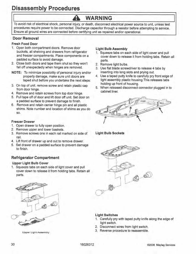
Refrigerator CompartmentUpper Light Bulb Cover .......................................... 30Light Bulb Assembly .............................................. 30Light Bulb Sockets ................................................ 30Light Switches ....................................................... 30Fresh Food Thermistor ........................................... 31Water Tank ............................................................ 31
Water Dispenser Facade ....................................... 31Low Voltage Board ................................................. 31Chute Extension / Yoke Assembly ......................... 31
Ice Box CompartmentIce Bin Assembly ................................................... 31Icemaker Assembly ............................................... 31Ice Box Fan ........................................................... 31Auger Motor ........................................................... 31Solenoid ................................................................ 32Damper .................................................................. 32Ice Box Thermistor ................................................. 32
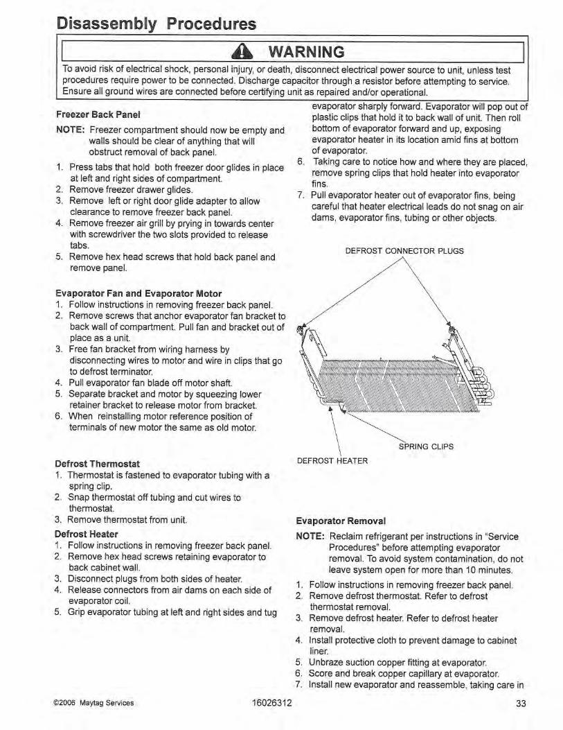
Freezer CompartmentFreezer Thermistor ................................................. 32Light Socket .......................................................... 32Light Switch ...........................................................32Freezer Back Panel ...............................................33Evaporator Fan and Evaporator Motor ................... 33Defrost Terminator (thermostat) .............................. 33Defrost Heater ....................................................... 33Evaporator Removal ...............................................33Drawer Assembly ................................................... 34Drawer Rails .......................................................... 34Rack and Pinion Gear ............................................34
Bottom of CabinetFront roller assembly ............................................. 34Rear roller assembly............................................34
Machine CompartmentCondenser Fan and Fan motor ............................... 34Compressor ...........................................................34Overload/Relay/Capacitor ....................................... 35Condensate Drain Pan ........................................... 35Condensate Drain Tube.......................................... 35Condenser Removal ...............................................35
Cabinet BackHigh Voltage Board ................................................ 35
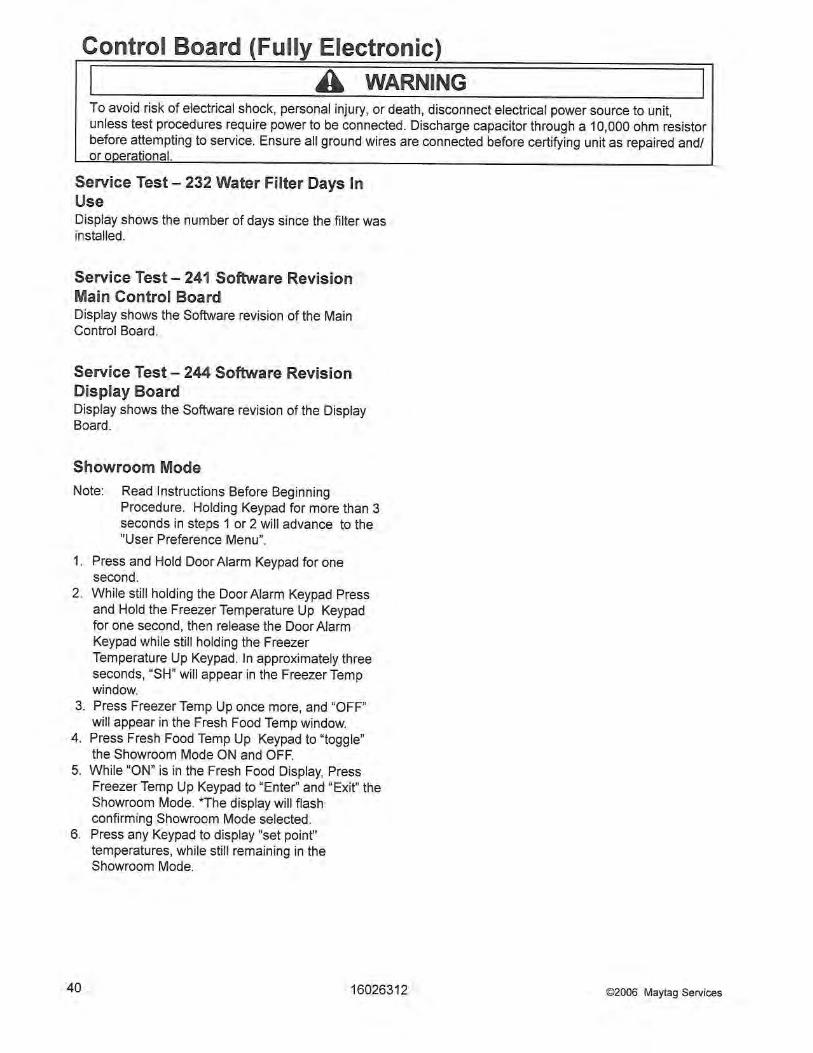
Control Board (Fully Electronic)Programming Mode ...............................................36Defrost Operation ................................................... 36Forced Defrost Mode ............................................. 36Service Test Mode ................................................. 37Show Room Mode ................................................. 40
Appendix A Owner’s Manual ........ ........................................A-1
Table of Contents

4 16026312 ©2006 Maytag Services
Product Design
To avoid risk of electrical shock, personal injury, or death, disconnect electrical power source to unit, unless testprocedures require power to be connected. Discharge capacitor through a resistor before attempting to service.Ensure all ground wires are connected before certifying unit as repaired and/or operational.
! WARNING
Refrigeration SystemCompressor forces high temperature vapor into fancooled tube and wire condenser where vapor is cooledand condensed into high pressure liquid by circulationof air across condenser coil. (See Refrigerant FlowDiagram, page 18)High pressure liquid passes into post-condenser loopwhich helps to prevent condensation around freezercompartment opening and through molecular sieve drierand into capillary tube. Small inside diameter ofcapillary offers resistance, decreasing pressure andtemperature of liquid discharged into evaporator.Capillary diameter and length is carefully sized for eachsystem.Capillary enters evaporator at top front. Combined liquidand saturated gas flows through front to bottom of coiland into suction line. Aluminium tube evaporator coil islocated in freezer compartment where circulatingevaporator fan moves air through coil and into fresh foodcompartment.Large surface of evaporator allows heat to be absorbedfrom both fresh food and freezer compartments byairflow over evaporator coil causing some of the liquid toevaporate. Temperature of evaporator tubing near end ofrunning cycle may vary from -13°F to -25°F.Saturated gas is drawn off through suction line wheresuperheated gas enters compressor. To raisetemperature of gas, suction line is placed in heatexchange with capillary.
Temperature ControlsFreezer compartment temperature is regulated by airsensing thermistor at top front of freezer compartmentwhich actuates compressor. Control should be set tomaintain freezer temperature between 0°F to -2°F.Fresh food compartment temperature is regulated by anair damper control governing amount of refrigerated airentering fresh food compartment from freezer. Freshfood compartment temperature should be between 38°Fand 40°F.Evaporator and Ice Box Fans are multiple speed lowvoltage fans that change speeds depending onconditions changing in refrigerator.
Defrost System Fully Electronic Defrost SystemThe Control Board adapts the compressor run timebetween defrosts to achieve optimum defrost intervalsby monitoring the length of time the defrost heater ison.After initial power up, defrost interval is 4 hourscompressor run time. Defrost occurs immediately afterthe 4 hours.Note: Once unit is ready to defrost there is a 4 minute
wait time prior to the beginning of the defrostcycle.
Component Testing
! WARNING To avoid risk of electrical shock, personal injury, or death, disconnect electrical power source to unit, unless test procedures require power to be connected. Discharge capacitor through a resistor before attempting to service. Ensure all ground wires are connected before certifying unit as repaired and/or operational.
©2006 Maytag Services 16026312 5
Component Description Test Procedures Compressor
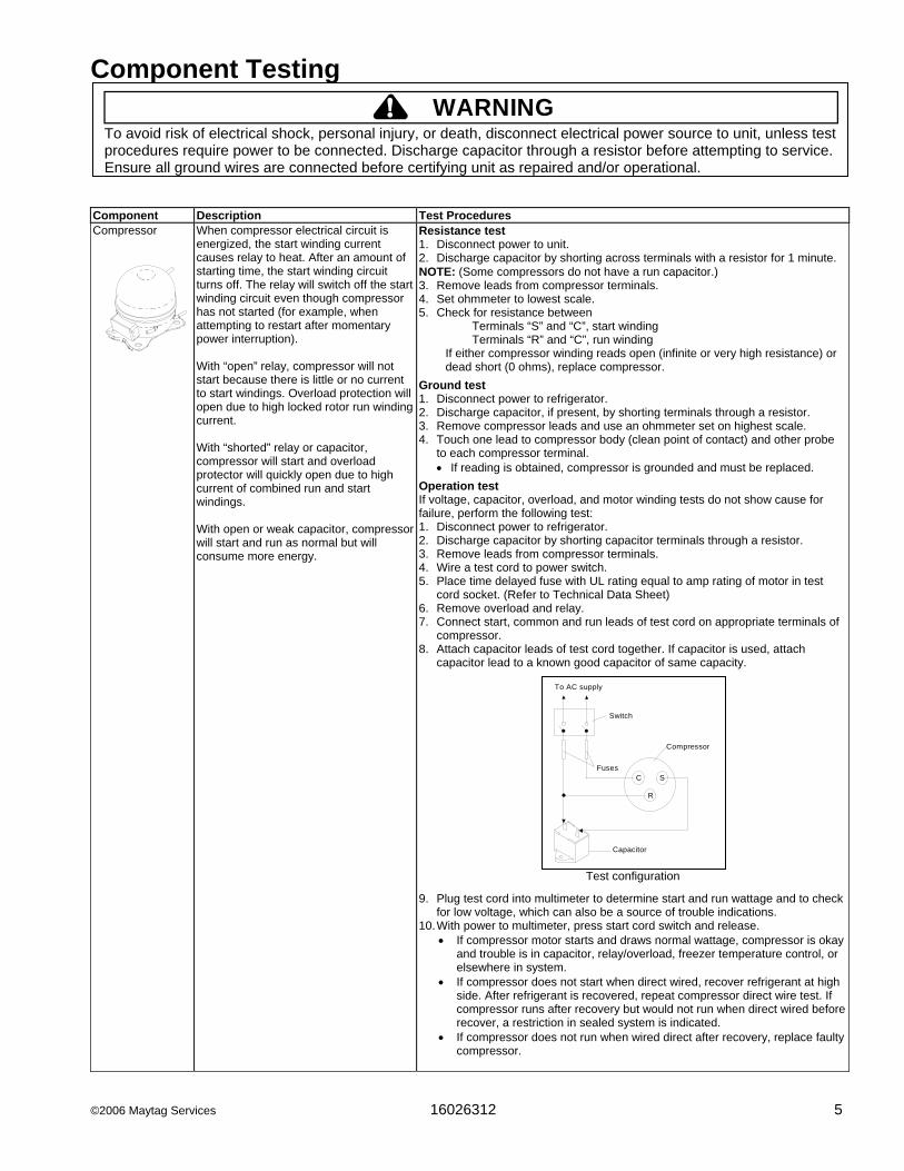
When compressor electrical circuit is energized, the start winding current causes relay to heat. After an amount of starting time, the start winding circuit turns off. The relay will switch off the start winding circuit even though compressor has not started (for example, when attempting to restart after momentary power interruption). With “open” relay, compressor will not start because there is little or no current to start windings. Overload protection will open due to high locked rotor run winding current. With “shorted” relay or capacitor, compressor will start and overload protector will quickly open due to high current of combined run and start windings. With open or weak capacitor, compressor will start and run as normal but will consume more energy.
Resistance test 1. Disconnect power to unit. 2. Discharge capacitor by shorting across terminals with a resistor for 1 minute. NOTE: (Some compressors do not have a run capacitor.) 3. Remove leads from compressor terminals. 4. Set ohmmeter to lowest scale. 5. Check for resistance between Terminals “S” and “C”, start winding Terminals “R” and “C”, run winding
If either compressor winding reads open (infinite or very high resistance) or dead short (0 ohms), replace compressor.
Ground test 1. Disconnect power to refrigerator. 2. Discharge capacitor, if present, by shorting terminals through a resistor. 3. Remove compressor leads and use an ohmmeter set on highest scale. 4. Touch one lead to compressor body (clean point of contact) and other probe
to each compressor terminal. • If reading is obtained, compressor is grounded and must be replaced.
Operation test If voltage, capacitor, overload, and motor winding tests do not show cause for failure, perform the following test: 1. Disconnect power to refrigerator. 2. Discharge capacitor by shorting capacitor terminals through a resistor. 3. Remove leads from compressor terminals. 4. Wire a test cord to power switch. 5. Place time delayed fuse with UL rating equal to amp rating of motor in test
cord socket. (Refer to Technical Data Sheet) 6. Remove overload and relay. 7. Connect start, common and run leads of test cord on appropriate terminals of
compressor. 8. Attach capacitor leads of test cord together. If capacitor is used, attach
capacitor lead to a known good capacitor of same capacity.
Test configuration
9. Plug test cord into multimeter to determine start and run wattage and to check for low voltage, which can also be a source of trouble indications.
10. With power to multimeter, press start cord switch and release. • If compressor motor starts and draws normal wattage, compressor is okay
and trouble is in capacitor, relay/overload, freezer temperature control, or elsewhere in system.
• If compressor does not start when direct wired, recover refrigerant at high side. After refrigerant is recovered, repeat compressor direct wire test. If compressor runs after recovery but would not run when direct wired before recover, a restriction in sealed system is indicated.
• If compressor does not run when wired direct after recovery, replace faulty compressor.
C
R
SFuses
Capacitor
Compressor
Switch
To AC supply

Component Testing
! WARNING To avoid risk of electrical shock, personal injury, or death, disconnect electrical power source to unit, unless test procedures require power to be connected. Discharge capacitor through a resistor before attempting to service. Ensure all ground wires are connected before certifying unit as repaired and/or operational.
6 16026312 ©2006 Maytag Services
Component Description Test Procedures Capacitor
Run capacitor connects to relay terminal 3 and L side of line. Some compressors do not require a run capacitor; refer to the Technical Data Sheet for the unit being serviced.
1. Disconnect power to refrigerator. 2. Remove capacitor cover and disconnect capacitor wires. 3. Discharge capacitor by shorting across terminals with a resistor for 1 minute.4. Check resistance across capacitor terminals with ohmmeter set on “X1K”
scale. • Good—needle swings to 0 ohms and slowly moves back to infinity. • Open—needle does not move. Replace capacitor. • Shorted—needle moves to zero and stays. Replace capacitor. • High resistance leak—needle jumps toward 0 and then moves back to
constant high resistance (not infinity).
Condenser Condenser is a tube and wire construction located in machine compartment. Condenser is on high pressure discharge side of compressor. Condenser function is to transfer heat absorbed by refrigerant to ambient. Higher pressure gas is routed to condenser where, as gas temperature is reduced, gas condenses into a high pressure liquid state. Heat transfer takes place because discharged gas is at a higher temperature than air that is passing over condenser. It is very important that adequate air flow over condenser is maintained. Condenser is air cooled by condenser fan motor. If efficiency of heat transfer from condenser to surrounding air is impaired, condensing temperature becomes higher. High liquid temperature means liquid will not remove as much heat during boiling in evaporator as under normal conditions. This would be indicated by higher than normal head pressures, long run time, and high wattage. Remove any lint or other accumulation, that would restrict normal air movement through condenser. From condenser the refrigerant flows into a post condenser loop which helps control exterior condensation on flange, center mullion, and around freezer door. Refrigerant flows through the drier to evaporator and into compressor through suction line.
Leaks in condenser can usually be detected by using an electronic leak detector or soap solution. Look for signs of compressor oil when checking for leaks. A certain amount of compressor oil is circulated with refrigerant. Leaks in post condenser loop are rare because loop is a one-piece copper tube. For minute leaks 1. Separate condenser from rest of refrigeration system and pressurize
condenser up to a maximum of 235 PSI with a refrigerant and dry nitrogen combination.
2. Recheck for leaks.
WARNING! To avoid electrical shock which can cause severe personal injury or death, discharge capacitor through a resistor before handling.
WARNING!To avoid severe personal injury or death from sudden eruption of high pressures gases, observe the following:
Protect against a sudden eruption if high pressures are required for leak checking. Do not use high pressure compressed gases in refrigeration systems without a reliable pressure regulator and pressure relief valve in the lines.
Component Testing
! WARNING To avoid risk of electrical shock, personal injury, or death, disconnect electrical power source to unit, unless test procedures require power to be connected. Discharge capacitor through a resistor before attempting to service. Ensure all ground wires are connected before certifying unit as repaired and/or operational.
©2006 Maytag Services 16026312 7
Component Description Test Procedures Overload / Relay
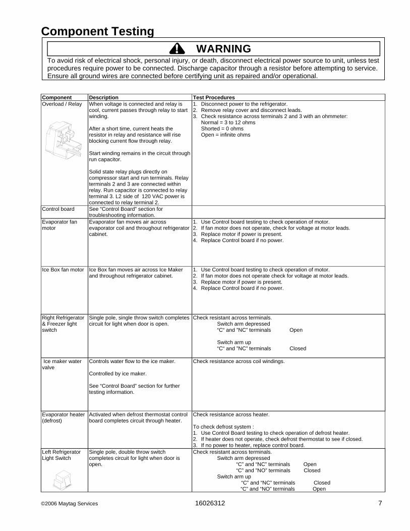
When voltage is connected and relay is cool, current passes through relay to start winding. After a short time, current heats the resistor in relay and resistance will rise blocking current flow through relay. Start winding remains in the circuit through run capacitor. Solid state relay plugs directly on compressor start and run terminals. Relay terminals 2 and 3 are connected within relay. Run capacitor is connected to relay terminal 3. L2 side of 120 VAC power is connected to relay terminal 2.
1. Disconnect power to the refrigerator. 2. Remove relay cover and disconnect leads. 3. Check resistance across terminals 2 and 3 with an ohmmeter: Normal = 3 to 12 ohms Shorted = 0 ohms Open = infinite ohms
Control board
See “Control Board” section for troubleshooting information.
Evaporator fan motor
Evaporator fan moves air across evaporator coil and throughout refrigerator cabinet.
1. Use Control board testing to check operation of motor. 2. If fan motor does not operate, check for voltage at motor leads. 3. Replace motor if power is present. 4. Replace Control board if no power.
Ice Box fan motor
Ice Box fan moves air across Ice Maker and throughout refrigerator cabinet.
1. Use Control board testing to check operation of motor. 2. If fan motor does not operate check for voltage at motor leads. 3. Replace motor if power is present. 4. Replace Control board if no power.
Right Refrigerator & Freezer light switch
Single pole, single throw switch completes circuit for light when door is open.
Check resistant across terminals. Switch arm depressed “C“ and ”NC” terminals Open Switch arm up “C“ and ”NC” terminals Closed
Ice maker water valve
Controls water flow to the ice maker. Controlled by ice maker. See “Control Board” section for further testing information.
Check resistance across coil windings.
Evaporator heater (defrost)
Activated when defrost thermostat control board completes circuit through heater.
Check resistance across heater. To check defrost system : 1. Use Control Board testing to check operation of defrost heater. 2. If heater does not operate, check defrost thermostat to see if closed. 3. If no power to heater, replace control board.
Left Refrigerator Light Switch
Single pole, double throw switch completes circuit for light when door is open.
Check resistant across terminals. Switch arm depressed “C” and “NC” terminals Open “C” and ”NO” terminals Closed Switch arm up “C” and “NC” terminals Closed “C” and “NO” terminals Open
Component Testing
! WARNING To avoid risk of electrical shock, personal injury, or death, disconnect electrical power source to unit, unless test procedures require power to be connected. Discharge capacitor through a resistor before attempting to service. Ensure all ground wires are connected before certifying unit as repaired and/or operational.
8 16026312 ©2006 Maytag Services
Component Description Test Procedures Drier
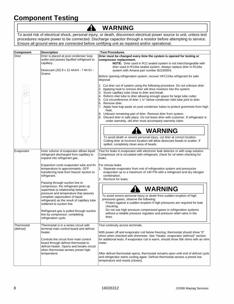
Drier is placed at post condenser loop outlet and passes liquified refrigerant to capillary. Desiccant (20) 8 x 12 4AXH - 7 M>S> -Grams
Drier must be changed every time the system is opened for testing or compressor replacement. NOTE: Drier used in R12 sealed system is not interchangeable with drier used in R134a sealed system. Always replace drier in R134a system with Amana part number B2150504.
Before opening refrigeration system, recover HFC134a refrigerant for safe disposal.
1. Cut drier out of system using the following procedure. Do not unbraze drier. 2. Applying heat to remove drier will drive moisture into the system. 3. Score capillary tube close to drier and break. 4. Reform inlet tube to drier allowing enough space for large tube cutter. 5. Cut circumference of drier 1 ¼" below condenser inlet tube joint to drier. 6. Remove drier. 7. Apply heat trap paste on post condenser tubes to protect grommets from high
heat. 8. Unbraze remaining part of drier. Remove drier from system. 9. Discard drier in safe place. Do not leave drier with customer. If refrigerator is
under warranty, old drier must accompany warranty claim.
Evaporator Inner volume of evaporator allows liquid
refrigerant discharged from capillary to expand into refrigerant gas. Expansion cools evaporator tube and fin temperature to approximately -20°F transferring heat from freezer section to refrigerant. Passing through suction line to compressor, the refrigerant picks up superheat (a relationship between pressure and temperature that assures complete vaporization of liquid refrigerant) as the result of capillary tube soldered to suction line. Refrigerant gas is pulled through suction line by compressor, completing refrigeration cycle.
Test for leaks in evaporator with electronic leak detector or with soap solution. Compressor oil is circulated with refrigerant; check for oil when checking for leaks. For minute leaks 1. Separate evaporator from rest of refrigeration system and pressurize
evaporator up to a maximum of 140 PSI with a refrigerant and dry nitrogen combination.
2. Recheck for leaks.
Thermostat (defrost)
Thermostat is in a series circuit with terminal main control board and defrost heater. Controls the circuit from main control board through defrost thermostat to defrost heater. Opens and breaks circuit when thermostat senses preset high temperature.
Test continuity across terminals. With power off and evaporator coil below freezing, thermostat should show “0” ohms when checked with ohmmeter. See “Heater, evaporator (defrost)” section for additional tests. If evaporator coil is warm, should show 56k ohms with an ohm meter. After defrost thermostat opens, thermostat remains open until end of defrost cycle and refrigerator starts cooling again. Defrost thermostat senses a preset low temperature and resets (closes).
WARNING!To avoid severe personal injury or death from sudden eruption of high pressures gases, observe the following:
Protect against a sudden eruption if high pressures are required for leak checking. Do not use high pressure compressed gases in refrigeration systems without a reliable pressure regulator and pressure relief valve in the lines.
WARNING!To avoid death or severe personal injury, cut drier at correct location. Cutting drier at incorrect location will allow desiccant beads to scatter. If spilled, completely clean area of beads.
Component Testing
! WARNING To avoid risk of electrical shock, personal injury, or death, disconnect electrical power source to unit, unless test procedures require power to be connected. Discharge capacitor through a resistor before attempting to service. Ensure all ground wires are connected before certifying unit as repaired and/or operational.
©2006 Maytag Services 16026312 9
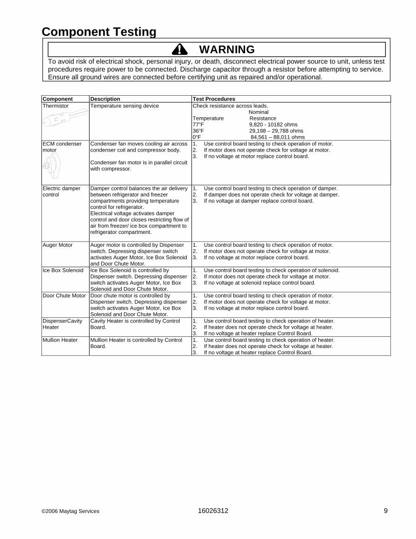
Component Description Test Procedures Thermistor
Temperature sensing device Check resistance across leads. Nominal Temperature Resistance 77°F 9,820 - 10182 ohms 36°F 29,198 – 29,788 ohms 0°F 84,561 – 88,011 ohms
ECM condenser motor
Condenser fan moves cooling air across condenser coil and compressor body. Condenser fan motor is in parallel circuit with compressor.
1. Use control board testing to check operation of motor. 2. If motor does not operate check for voltage at motor. 3. If no voltage at motor replace control board.
Electric damper control
Damper control balances the air delivery between refrigerator and freezer compartments providing temperature control for refrigerator. Electrical voltage activates damper control and door closes restricting flow of air from freezer/ ice box compartment to refrigerator compartment.
1. Use control board testing to check operation of damper. 2. If damper does not operate check for voltage at damper. 3. If no voltage at damper replace control board.
Auger Motor Auger motor is controlled by Dispenser switch. Depressing dispenser switch activates Auger Motor, Ice Box Solenoid and Door Chute Motor.
1. Use control board testing to check operation of motor. 2. If motor does not operate check for voltage at motor. 3. If no voltage at motor replace control board.
Ice Box Solenoid Ice Box Solenoid is controlled by Dispenser switch. Depressing dispenser switch activates Auger Motor, Ice Box Solenoid and Door Chute Motor.
1. Use control board testing to check operation of solenoid. 2. If motor does not operate check for voltage at motor. 3. If no voltage at solenoid replace control board.
Door Chute Motor Door chute motor is controlled by Dispenser switch. Depressing dispenser switch activates Auger Motor, Ice Box Solenoid and Door Chute Motor.
1. Use control board testing to check operation of motor. 2. If motor does not operate check for voltage at motor. 3. If no voltage at motor replace control board.
DispenserCavity Heater
Cavity Heater is controlled by Control Board.
1. Use control board testing to check operation of heater. 2. If heater does not operate check for voltage at heater. 3. If no voltage at heater replace Control Board.
Mullion Heater Mullion Heater is controlled by Control Board.
1. Use control board testing to check operation of heater. 2. If heater does not operate check for voltage at heater. 3. If no voltage at heater replace Control Board.

10 16026312 ©2006 Maytag Services
Drier ReplacementBefore opening refrigeration system, recoverHFC134a refrigerant for safe disposal.Every time sealed HFC134a system is repaired, drierfilter must be replaced with, part # B2150504.Cut drier out of system by completing the followingsteps. Do not unbraze drier filter. Applying heat toremove drier will drive moisture into system.
To avoid risk of severe personal injury or death, cutdrier at correct location. Cutting drier at incorrectlocation will allow desiccant beads to scatter.Completely clean area of beads, if spilled.
1. Score capillary tube close to drier and break.2. Reform inlet tube to drier allowing enough space
for large tube cutter.3. Cut circumference of drier at 1-1/4", below
condenser inlet tube joint to drier.4. Remove drier.5. Apply heat trap paste on post condenser tubes to
protect grommets from high heat.6. Unbraze remaining part of drier. Remove drier
from system.7. Discard drier in safe place. Do not leave drier with
customer. If refrigerator is under warranty, olddrier must accompany warranty claim.
Service Procedures
Service EquipmentListed below is equipment needed for proper servicingof HFC134a systems. Verify equipment is confirmedby manufacturer as being compatible with HFC134aand ester oil system.Equipment must be exclusively used for HFC134a.Exclusive use of equipment only applies to italic items.• Evacuation pump
Check with vacuum pump supplier to verify equipmentis compatible for HFC134a. Robinair, Model 15600
2 stage, 6 cubic feet per minute pump isrecommended.
• Four-way manifold gauge set, with low loss hoses• Leak detector• Charging cylinder• Line piercing saddle valve
(Schroeder valves). Seals must be HFC134a andester oil compatible. Line piercing valves may be usedfor diagnosis but are not suitable for evacuation orcharging, due to minute holes pierced in tubing. Donot leave mechanical access valves on system.Valves eventually will leak. Molecules of HFC134a aresmaller than other refrigerants and will leak whereother refrigerants would not.
• Swaging tools• Flaring tools• Tubing cutter• Flux• Sil-Fos• Silver solder• Oil for swaging and flaring
Use only part # R0157532• Copper tubing
Use only part # R0174075 and # R0174076• Dry nitrogen
99.5% minimum purity, with -40°F or lower dew point• Crimp tool• Tube bender• Micron vacuum gauge• Process tube adaptor kit• Heat trap paste• ICI appliance grade HFC134a
To avoid risk of electrical shock, personal injury, or death, disconnect electrical power source to unit, unless testprocedures require power to be connected. Discharge capacitor through a 10,000 ohm resistor before attemptingto service. Ensure all ground wires are connected before certifying unit as repaired and/or operational.
! WARNING
WARNING!

©2006 Maytag Services 16026312 11
Refrigerant Precautions
WARNING!To avoid risk of personal injury, do not allowrefrigerant to contact eyes or skin.
CAUTION!To avoid risk of property damage, do not userefrigerant other than that shown on unit serialnumber identification plate.
NOTE: All precautionary measures recommended byrefrigerant manufacturers and suppliers applyand should be observed.
Line Piercing ValvesLine piercing valves can be used for diagnosis, butare not suitable for evacuating or charging due toholes pierced in tubing by valves.NOTE: Do not leave line piercing valves on system.
Connection between valve and tubing is nothermetically sealed. Leaks will occur.
Open LinesDuring any processing of refrigeration system, neverleave lines open to atmosphere. Open lines allow watervapor to enter system, making proper evacuation moredifficult.
Compressor Operational Test(short term testing only)If compressor voltage, capacitor, overload, and motorwinding tests are successful (do not indicate a fault),perform the following test:1.Disconnect power to unit.2.Discharge capacitor by shorting capacitor
terminals through a resistor.NOTE: Not all units have run capacitor.3.Remove leads from compressor terminals.4.Attach test cord to compressor windings.
• Common lead on test cord attaches to C terminalon compressor.
• Start lead on test cord attaches to S terminal oncompressor.
• Run lead on test cord attaches to R terminal oncompressor.
Service Procedures
C
R
SFuses
Capacitor
Compressor
Switch
To AC supply
Attaching Capacitor for Compressor Test5. Connect a known good capacitor into circuit as shown
above. For proper capacitor size and rating, seetechnical data sheet for unit under test.
NOTE: Ensure test cord cables and fuses meetspecifications for unit under test (see TechnicalSheet for unit under test).
6. Replace compressor protector cover securely.7. Plug test cord into outlet, then press and release start
cord switch.
CAUTION!To avoid risk of damage to compressor windings,immediately disconnect (unplug) test cord from powersource if compressor does not start. Damage tocompressor windings occurs if windings remainenergized when compressor is not running.
If compressor runs when direct wired, it is workingproperly. Malfunction is elsewhere in system.If compressor does not start when direct wired, recoversystem at high side. After the system is recovered,repeat compressor direct wire test.If compressor runs after system is recovered (butwould not operate when wired direct before recovery) arestriction in sealed system is indicated.If motor does not run when wired direct after recovery,replace faulty compressor.
To avoid risk of electrical shock, personal injury, or death, disconnect electrical power source to unit, unless testprocedures require power to be connected. Discharge capacitor through a 10,000 ohm resistor before attemptingto service. Ensure all ground wires are connected before certifying unit as repaired and/or operational.
! WARNING

12 16026312 ©2006 Maytag Services
Dehydrating Sealed Refrigeration SystemMoisture in a refrigerator sealed system exposed toheat generated by the compressor and motor reactschemically with refrigerant and oil in the system andforms corrosive hydrochloric and hydrofluoric acids.These acids contribute to breakdown of motor windinginsulation and corrosion of compressor working parts,causing compressor failure.In addition, sludge, a residue of the chemical reaction,coats all surfaces of sealed system, and will eventuallyrestrict refrigerant flow through capillary tube.To dehydrate sealed system, evacuate system (seeparagraph Evacuation).
Leak Testing
DANGER!To avoid risk of serious injury or death from violentexplosions, NEVER use oxygen or acetylene forpressure testing or cleaning out of refrigerationsystems. Free oxygen will explode on contact withoil. Acetylene will explode spontaneously when putunder pressure.
It is important to check sealed system for refrigerantleaks. Undetected leaks can lead to repeated servicecalls and eventually result in system contamination,restrictions, and premature compressor failure.
Refrigerant leaks are best detected with halide orelectronic leak detectors.
Testing Systems Containing a Refrigerant Charge1. Stop unit operation (turn refrigerator off).2. Holding leak detector exploring tube as close to
system tubing as possible, check all piping, joints,and fittings.
NOTE: Use soap suds on areas leak detector cannotreach or reliably test.
Testing Systems Containing No Refrigerant Charge1. Connect cylinder of nitrogen, through gauge
manifold, to process tube of compressor and liquidline strainer.
2. Open valves on nitrogen cylinder and gauge manifold.Allow pressure to build within sealed system.
3. Check for leaks using soap suds.If a leak is detected in a joint, do not to attempt to repairby applying additional brazing material. Joint must bedisassembled, cleaned and rebrazed. Capture refrigerantcharge (if system is charged), unbraze joint, clean allparts, then rebraze.
If leak is detected in tubing, replace tubing. If leak isdetected in either coil, replace faulty coil.
Service Procedures
! WARNINGTo avoid risk of electrical shock, personal injury, or death, disconnect electrical power source to unit, unless testprocedures require power to be connected. Discharge capacitor through a 10,000 ohm resistor before attemptingto service. Ensure all ground wires are connected before certifying unit as repaired and/or operational.
©2006 Maytag Services 16026312 13
Service Procedures
! WARNINGTo avoid risk of electrical shock, personal injury, or death, disconnect electrical power source to unit, unless testprocedures require power to be connected. Discharge capacitor through a 10,000 ohm resistor before attemptingto service. Ensure all ground wires are connected before certifying unit as repaired and/or operational.
RestrictionsSymptomsRestrictions in sealed system most often occur atcapillary tube or filter drier, but can exist anywhere onliquid side of system.Restrictions reduce refrigerant flow rate and heatremoval rate. Wattage drops because compressor isnot circulating normal amount of refrigerants.Common causes of total restrictions are moisture,poorly soldered joints, or solid contaminants. Moisturefreezes at evaporator inlet end of capillary tube. Solidcontaminants collect in filter drier.If restriction is on low side, suction pressure will be in avacuum and head pressure will be near normal.If restriction is on high side, suction pressure will be ina vacuum and head pressure will be higher thannormal during pump out cycle.Refrigeration occurs on low pressure side of partialrestriction. There will be a temperature difference atthe point of restriction. Frost and/or condensation willbe present in most cases at the point of restriction.Also, system requires longer to equalize.Slight or partial restriction can give the samesymptoms as refrigerant shortage including lower thannormal back pressure, head pressure, wattage, andwarmer temperatures.Total restriction on the discharge side of compressor,when restriction is between compressor and first halfof condenser, results in higher than normal headpressure and wattage while low side is being pumpedout.Testing for RestrictionsTo determine if a restriction exists:1. Attach gauge and manifold between suction and
discharge sides of sealed system.2. Turn unit on and allow pressure on each side to
stabilize. Inspect condenser side of system. Tubingon condenser should be warm and temperatureshould be equal throughout (no sudden drops at anypoint along tubing).• If temperature of condenser tubing is consistent
throughout, go to step 4.• If temperature of condenser tubing drops suddenly
at any point, tubing is restricted at point oftemperature drop (if restriction is severe, frost mayform at point of restriction and extend down indirection of refrigerant flow in system). Go to step 5.
3. Visually check system for kinks in refrigeration linewhich is causing restriction. Correct kink and repeatstep 2.
4. Turn unit off and time how long it takes high and lowpressure gauges to equalize:• If pressure equalization takes longer than 10
minutes, a restriction exists in the capillary tube ordrier filter. Go to step 5.
• If pressure equalization takes less than 10 minutes,system is not restricted. Check for other possiblecauses of malfunction.
5. Recover refrigerant in sealed system.NOTE: Before opening any refrigeration system,
capture refrigerant in system for safe disposal.6. Remove power from unit.
To avoid risk of personal injury or property damage,take necessary precautions against hightemperatures required for brazing.
7. Remove and replace restricted device.8. Evacuate sealed system.9. Charge system to specification.NOTE: Do not use captured or recycled refrigerant in
units. Captured or recycled refrigerant voids anycompressor manufacturer's warranty.
NOTE: Charge system with exact amount of refrigerant.Refer to unit nameplate for correct refrigerantcharge. Inaccurately charged system will causefuture problems.
CAUTION!

14 16026312 ©2006 Maytag Services
Evacuation and Charging
To avoid risk of fire, sealed refrigeration systemmust be air free. To avoid risk of air contamination,follow evacuation procedures exactly.
NOTE: Before opening any refrigeration system, EPAregulations require refrigerant in system to becaptured for safe disposal.
Proper evacuation of sealed refrigeration system is animportant service procedure. Usable life andoperational efficiency greatly depends upon howcompletely air, moisture and other non-condensablesare evacuated from sealed system.Air in sealed system causes high condensingtemperature and pressure, resulting in increasedpower requirements and reduced performance.Moisture in sealed system chemically reacts withrefrigerant and oil to form corrosive hydrofluoric andhydrochloric acids. These acids attack motor windingsand parts, causing premature breakdown.Before opening system, evaporator coil must be atambient temperature to minimize moisture infiltrationinto system.EvacuationTo evacuate sealed refrigeration system:
1. Connect vacuum pump, vacuum tight manifold setwith high vacuum hoses, thermocouple vacuumgauge and charging cylinder as shown in illustration.Evacuation should be done through I.D. opening oftubes not through line piercing valve.
2. Connect low side line to compressor process tube.3. Connect high side line to drier/process tube.4. Evacuate both simultaneously. With valve “C” and “F”
closed, open all other valves and start vacuum pump.
Vacuum Pump
.6 cm CopperTubing
CompressorCompressorProcessTube
Charging Hose
ThermistorVacuum Gauge
Low Side Gauge
EValve
B
DValve
High Side Gauge
Charging Hose
Drier/Process Tube
FValve
ChargingCylinder
C
A
Equipment Setup For Evacuation And Charging
5. After compound gauge (low side) drops toapproximately 29 inches gauge, open valve “C” tovacuum thermocouple gauge and take micronreading.
NOTE: A high vacuum pump can only produce a goodvacuum if oil in pump is not contaminated.
6. Continue evacuating system until vacuum gaugeregisters 600 microns.
7. At 600 microns, close valve “A” to vacuum pump andallow micron reading in system to balance. Micronlevel will rise.• If in 2 minutes, micron level stabilizes at 1000
microns or below, system is ready to be charged.• If micron level rises above 1000 microns and
stabilizes, open valve “A” and continue evacuating.• If micron reading rises rapidly and does not
stabilize, a leak still exists in system.Close valve “A” to vacuum pump and valve “C” tovacuum gauge. Invert charging cylinder and opencharging cylinder valve “F” to add partial charge forleak checking. With leak detector, check manifoldconnections and system for leaks. After locatingleak, capture refrigerant, repair leak, and begin atstep 1.
Service Procedures
! WARNINGTo avoid risk of electrical shock, personal injury, or death, disconnect electrical power source to unit, unless testprocedures require power to be connected. Discharge capacitor through a 10,000 ohm resistor before attemptingto service. Ensure all ground wires are connected before certifying unit as repaired and/or operational.
CAUTION!

©2006 Maytag Services 16026312 15
ChargingNOTE: Do not use captured or recycled refrigerant in
units. Captured or recycled refrigerant voids anywarranty.
NOTE: Charge system with exact amount of refrigerant.Refer to unit serial plate for correct refrigerantcharge. Inaccurately charged system will causefuture problems.
To charge system:
1. Close valves “A” to vacuum pump and “C” to vacuumgauge and “E” to low side manifold gauge.
2. Set scale on dial-a-charge cylinder for correspondingHFC134a pressure reading.
3. Open valve “F” to charging cylinder and let exactamount of refrigerant flow from cylinder into system.Close valve.Low side gauge pressure should rise shortly afteropening charging cylinder valve as system pressureequalizes through capillary tube.If pressure does not equalize, a restriction typicallyexists at capillary/drier braze joint.
4. If pressure equalizes, open valve “E” to low sidemanifold gauge and pinch off high side drier processtube.
5. Start compressor and draw remaining refrigerant fromcharging hoses and manifold into compressorthrough compressor process tube.
6. To check high side pinch-off drier process tube. Closevalve “D” to high side gauge. If high side pressurerises, repeat high side pinch-off and open valve “D”.Repeat until high side pinch-off does not leak.
7. Pinch-off compressor process tube and removecharging hose. Braze stub closed while compressor isoperating.
8. Disconnect power. Remove charging hose and brazehigh side drier process tube closed.
9. Recheck for refrigerant leaks.
Service Procedures
! WARNINGTo avoid risk of electrical shock, personal injury, or death, disconnect electrical power source to unit, unless testprocedures require power to be connected. Discharge capacitor through a 10,000 ohm resistor before attemptingto service. Ensure all ground wires are connected before certifying unit as repaired and/or operational.
Refrigerant ChargeRefrigerant charge in all capillary tube systems iscritical and exact amount is required for properperformance. Factory charges are shown on serialplate.NOTE: Do not use refrigerant other than shown on
serial plate.
16 16026312 ©2006 Maytag Services
To minimize contamination, exercise extreme carewhen servicing HFC134A sealed systems.
• No trace of other refrigerants is allowed in HFC134asystems. Chlorinated molecules in other refrigerantssuch as CFC12, etc. will lead to capillary tubeplugging.
• Ester oil is used in HFC134a systems. Do not usemineral oil. HFC134a and mineral oils cannot bemixed. If mineral oils were used in HFC134a systems,lubricant would not return to compressor and wouldcause early compressor failure. If significant amount ofoil has been lost from compressor, replace oil ratherthan adding oil.
• Ester oils used in HFC134a systems are sohydroscopic that by the time an inadequate systemperformance is detected, oil will be saturated withmoisture.
• CFC12 has much higher tolerance to systemprocessing materials, such as drawing compounds,rust inhibitors, and cleaning compounds, thanHFC134a. Such materials are not soluble in HFC134asystems. If materials were to be washed from systemsurfaces by ester oils, they could accumulate andeventually plug capillary tube.
• Care must be taken to minimize moisture enteringHFC134a system. Do not leave compressor or systemopen to atmosphere for more than 10 minutes.Excessive moisture in HFC134a system will react withcompressor oil and generate acid.
• Compressor must be replaced when performing lowside leak repair.
• Drier filter must always be replaced with service drierfilter, part #B2150504.Important: Unbrazing drier filter from tubing will drivemoisture from desiccant and into system, causingacids to form. Do not unbraze filter drier from tubing. IfCFC12 service drier was installed in HFC134A system,drier could overload due to excessive moisture.
• HFC134a compatible copper tubing, part #R0174075(1/4" O.D. X 18" length) and part #R0174076 (5/16"O.D. X 24" length) must be used when replacingtubing.
• Avoid system contamination by using Towerdraw E610evaporating oil, part # R0157532, when flaring,swaging, or cutting refrigeration tubing.
Service Procedures
HFC134a Service InformationHFC134a is alternative refrigerant for CFC12.HFC134a has an ozone depletion potential (ODP)factor of 0.0 and a global warming potential (GWP)factor of 0.27. HFC134a is not flammable and hasacceptable toxicity levels. HFC134a is notinterchangeable with CFC12. There are significantdifferences between HFC134a and CFC12 which mustbe considered when handling and processingrefrigeration system.
Health, Safety, and HandlingHealth, safety and handling considerations forHFC134A are virtually no different than those forCFC12.
To avoid risk of electrical shock, personal injury, or death, disconnect electrical power source to unit, unless testprocedures require power to be connected. Discharge capacitor through a 10,000 ohm resistor before attemptingto service. Ensure all ground wires are connected before certifying unit as repaired and/or operational.
! WARNING
CAUTION!
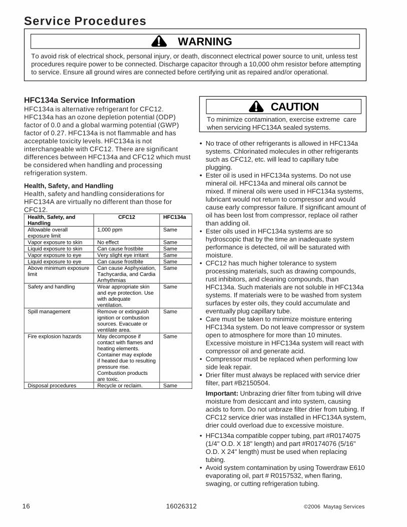
Health, Safety, andHandling
CFC12 HFC134a
Allowable overallexposure limit
1,000 ppm Same
Vapor exposure to skin No effect SameLiquid exposure to skin Can cause frostbite SameVapor exposure to eye Very slight eye irritant SameLiquid exposure to eye Can cause frostbite SameAbove minimum exposurelimit
Can cause Asphyxiation,Tachycardia, and CardiaArrhythmias
Same
Safety and handling Wear appropriate skinand eye protection. Usewith adequateventilation.
Same
Spill management Remove or extinguishignition or combustionsources. Evacuate orventilate area.
Same
Fire explosion hazards May decompose ifcontact with flames andheating elements.Container may explodeif heated due to resultingpressure rise.Combustion productsare toxic.
Same
Disposal procedures Recycle or reclaim. Same

©2006 Maytag Services 16026312 17
To avoid death or severe personal injury, never useoxygen, air or acetylene for pressure testing orclean out of refrigeration system. Use of oxygen,air, or acetylene may result in violent explosion.Oxygen may explode on contact with oil andacetylene will spontaneously explode when underpressure.
Replacement Service CompressorHFC134a service compressors will be charged withester oil and pressurized with dry nitrogen. Beforereplacement compressor is installed, pull out 1 rubberplug. A pop from pressure release should be heard. Ifa pop sound is not heard, do not use compressor.Positive pressure in compressor is vital to keepmoisture out of ester oil. Do not leave compressoropen to atmosphere for more than 10 minutes.Compressor Testing Procedures
Refer to Technical Data Sheet “TemperatureRelationship Chart” for operating watts, test points,and temperature relationship test for unit being tested.• Temperature testing is accomplished by using 3 lead
thermocouple temperature tester in specific locations.Test point T-1 is outlet on evaporator coil and T-2 isinlet. Test point T-3 is suction tube temperaturemidway between where armaflex ends and suctionport of compressor (approximately 12 inches fromcompressor).
• Thermocouple tips should be attached securely tospecified locations.
• Do not test during initial pull down. Allow one off cycleor balanced temperature condition to occur beforeproceeding with testing.
• Refrigerator must operate minimum of 20 minutesafter thermocouples are installed.
• Turn control to colder to obtain required on time.• Wattage reading must be recorded in conjunction with
temperature test to confirm proper operation.• Suction and head pressures are listed on
“Temperature and Relationship Chart”. Normally theseare not required for diagnosis but used for confirmationon systems which have been opened.
Service Procedures
To avoid risk of electrical shock, personal injury, or death, disconnect electrical power source to unit, unless testprocedures require power to be connected. Discharge capacitor through a 10,000 ohm resistor before attemptingto service. Ensure all ground wires are connected before certifying unit as repaired and/or operational.
! WARNING
Brazing
CAUTION!To avoid risk of personal injury or property damage,take necessary precautions against hightemperatures required for brazing.
Satisfactory results require cleanliness, experience,and use of proper materials and equipment.Connections to be brazed must be properly sized, freeof rough edges, and clean.Generally accepted brazing materials are:• Copper to copper joints: SIL-FOS (alloy of 15
percent silver, 80 percent copper, and 5 percentphosphorous). Use without flux. Recommendedbrazing temperature is approximately 1400°F. Do notuse for copper to steel connection.
• Copper to steel joints: SILVER SOLDER (alloy of 30percent silver, 38 percent copper, 32 percent zinc).Use with fluoride based flux. Recommended brazingtemperature is approximately 1200°F.
• Steel to steel joints: SILVER SOLDER (see copperto steel joints).
• Brass to copper joints: SILVER SOLDER (seecopper to steel joints).
• Brass to steel joints: SILVER SOLDER (see copperto steel joints).
WARNING!
18 16026312 ©2006 Maytag Services
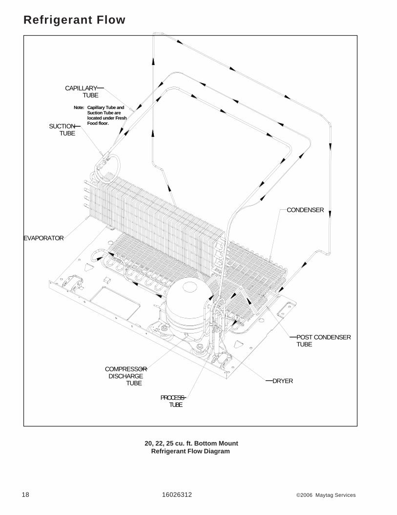
Refrigerant Flow
20, 22, 25 cu. ft. Bottom MountRefrigerant Flow Diagram
EVAPORATOR
COMPRESSORDISCHARGE
TUBE
CONDENSER
CAPILLARYTUBE
SUCTIONTUBE
DRYER
PROCESSTUBE
POST CONDENSERTUBE
Note: Capillary Tube and Suction Tube are located under Fresh Food floor.

©2006 Maytag Services 16026312 19
Cabinet Air Flow
20, 22, 25 cu. ft. Bottom MountCabinet Air Flow Diagram
20 16026312 ©2006 Maytag Services
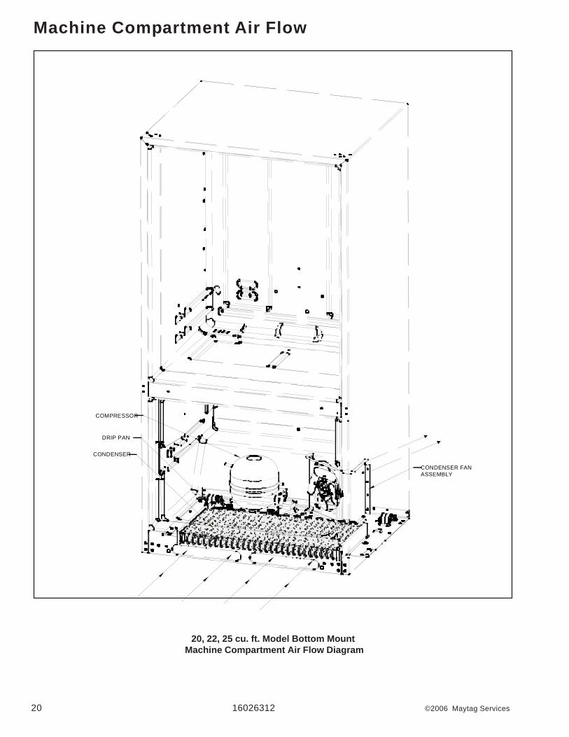
20, 22, 25 cu. ft. Model Bottom Mount Machine Compartment Air Flow Diagram
Machine Compartment Air Flow
COMPRESSOR
CONDENSER FANASSEMBLY
CONDENSER
DRIP PAN

©2006 Maytag Services 16026312 21
Water Dispenser
20, 22, 25 cu. ft. Model Bottom Mount Water Flow Diagram
WaterLine
Water Inletto Ice Maker
Water Inletto Dispenser
Water Solenoidto Ice Maker &Dispenser
Water Tankto Ice Maker &Dispenser
Water Solenoidto Ice Maker &Dispenser
Water Filter

22 16026312 ©2006 Maytag Services
20, 22, 25 cu. ft. Model Bottom Mount Water Flow Schematic
Water Flow Schematic
1/4 “ O.D.PLASTIC TUBING
1/4 “

©2006 Maytag Services 16026312 23
Typical External Sweat Pattern
TOP
Classification of Condensation1 = Haze or Fog2 = Beading3 = Beads or small drops4 = Drops running together
Conditions after 4 hour Laboratory Sweat Test: Ambient 90 dF Relative humidity 84% Refrigerator Temp. 40 dF Freezer Temp. 0 dF
#1 Sweat

24 16026312 ©2006 Maytag Services
Troubleshooting Chart
Symptom Possible Causes Corrective Action No power to unit Check for power at outlet. Check
fuse box/circuit breaker for blown fuse or tripped breaker. Replace or reset.
Faulty power cord Check with test light at unit; if no circuit and current is indicated at outlet, replace or repair.
Low voltage Check input voltage for proper voltage. Take appropriate action to correct voltage supply problem.
Faulty motor or freezer temperature control
Check all connections are tight and secure. Use Control Board Service Mode to check motor.
Faulty relay Check relay. Replace if necessary. Faulty compressor Check compressor motor windings
for opens/shorts. Perform compressor direct wiring test. Replace if necessary.
Unit does not run
Faulty overload Check overload for continuity. NOTE: Ensure compressor/overload are below trip temperature before testing.
Replace if necessary. Excessive door opening Consumer education Overloading of shelves Consumer education
Warm or hot foods placed in cabinet Consumer education
Cold control set too warm Set control to colder setting.
Poor door seal Level cabinet. Adjust hinges. Replace gasket.
Refrigerator airflow Check damper is opening by removing grille. With door open, damper should open. Replace if faulty. Check Ice Box fan for operation. Turn control setting to colder position.
Faulty condenser fan or evaporator fan
Use Control Board Service Mode to check motor. Check fan and wiring. Replace if necessary.
Refrigerator section too warm
Faulty compressor Use Control Board Service Mode to check motor. Replace compressor.
Troubleshooting chart on following pages contains symptoms that may be seen in malfunctioning units. Eachsymptom is accompanied by one or more possible causes and by a possible remedy or test to determine ifcomponents are working properly.
To avoid risk of electrical shock, personal injury, or death, disconnect electrical power source to unit, unless testprocedures require power to be connected. Discharge capacitor through a resistor before attempting to service.Ensure all ground wires are connected before certifying unit as repaired and/or operational.
! WARNING

©2006 Maytag Services 16026312 25
Symptom Possible Causes Corrective Action Refrigerator temperature control set too cold or faulty Fresh Food thermistor
Adjust refrigerator temperature control or check thermistor.
Refrigerator section too cold
Refrigerator airflow not properly adjusted
Check air flow.
Temperature controls set too warm Reset temperature controls. Poor door seal Level cabinet. Adjust hinges.
Replace gasket. Dirty condenser or obstructed grille Check condenser and grille. Clean. Faulty control Test main control. Replace if failed.
Freezer and refrigerator sections too warm
Refrigerant shortage or restriction Check for leak or restriction. Repair, evacuate and recharge system.
Freezer temp control set too cold Adjust freezer temperature control. Freezer section too cold Faulty control Test main control. Replace if failed. Temperature control set too cold Adjust temperature control. Dirty condenser or obstructed grille Check condenser and grille. Clean. Poor door seal Level cabinet. Adjust hinges.
Replace gasket. Faulty condenser fan or evaporator fan
Check fan and wiring. Replace if necessary.
Faulty control Test main control. Replace if failed. Refrigerant shortage or restriction Check for leak or restriction. Repair,
evacuate and recharge system. Refrigerant overcharge Check for overcharge. Evacuate and
recharge system.
Unit runs continuously
Air in system Check for low side leak. Repair, evacuate and recharge system.
Unit runs continuously. Temperature normal.
Ice on evaporator See “Ice on evaporator”.
Unit runs continuously. Temperature too cold.
Faulty defrost thermostat Check thermostat. Replace if necessary.
Loose flooring or floor not firm Repair floor or brace floor. Cabinet not level Level cabinet. Tubing in contact with cabinet, other tubing, or other metal
Adjust tubing.
Drip pan vibrating Adjust drain pan. Fan hitting another part Ensure fan is properly aligned and
all attaching hardware and brackets are tight and not worn. Tighten or replace.
Worn fan motor bearings Check motor for loss of lubricant or worn bearings. Replace if necessary.
Compressor mounting grommets worn or missing. Mounting hardware loose or missing
Tighten hardware. Replace grommets if necessary.
Noisy operation
Free or loose parts causing or allowing noise during operation
Inspect unit for parts that may have worked free or loose or missing screws. Repair as required.
Troubleshooting Chart
To avoid risk of electrical shock, personal injury, or death, disconnect electrical power source to unit, unless testprocedures require power to be connected. Discharge capacitor through a resistor before attempting to service.Ensure all ground wires are connected before certifying unit as repaired and/or operational.
! WARNING

26 16026312 ©2006 Maytag Services
Sym ptom Possib le Causes Corrective Action D efrost therm ostat faulty Check defrost therm ostat. R eplace if
fa iled.
Evapora tor fan faulty Check fan m otor. R eplace if fa iled.
D efrost heater rem ains open Check defrost heater continuity. Rep lace if fa iled.
D efrost control faulty Check m ain control and rep lace if fa iled.
O pen w ire or connector Check w iring and connections. Repa ir as necessary.
F rost or ice on evaporator
R efrigerant shortage or res tric tion Check for leak or res tric tion. R epair, evacuate and recharge sys tem .
Loose w ire connections Check w iring and connections. Repa ir as necessary.
Supply vo ltage out of specification Check input vo ltage. C orrect any supply problem s.
O verload protector open Check overload protector for continuity. If open, rep lace overload.
N O TE: Ensure overload/com pressor are below trip tem perature before testing.
Faulty com pressor m otor capacitor (som e com pressors do not require m otor capacitor)
Check capac itor for open/short. Rep lace if necessary.
N O TE: D ischarge capac itor before testing.
Faulty fan m otor Check fan m otor. R eplace if fa iled. R estric ted air flow Check condenser and grille for d irt.
C lean.
U nit s tarts and stops frequently (cycles on and off)
R efrigerant shortage or res tric tion Check for leak or res tric tion. Repair, evacuate and recharge sys tem .
In Sabbath m ode. If D ispenser lights are a lso off, see Sabbath m ode.
D oor has been left open for 10 continuous m inutes.
C lose all three doors for at least one second to reset contro l.
N o Interior lights, and app liance is still runn ing.
O pen circu it on neutra l s ide of light c ircuit.
O pen c ircu it (w iring or m ain control board) from neutral to light sockets.
Troubleshooting Chart
To avoid risk of electrical shock, personal injury, or death, disconnect electrical power source to unit, unless testprocedures require power to be connected. Discharge capacitor through a resistor before attempting to service.Ensure all ground wires are connected before certifying unit as repaired and/or operational.
! WARNING

System Diagnosis
©2006 Maytag Services 16026312 27
CONDITION
SUCTIONPRESSUREVARIATION
FROMNORMAL
HEADPRESSUREVARIATION
FROMNORMAL
T1 INLETTEMPERATURE
VARIATIONFROM NORMAL
T2 OUTLETTEMPERATURE
VARIATIONFROM NORMAL
T3 SUCTIONTEMPERATURE
VARIATIONFROM NORMAL
WATTAGEVARIATION
FROMNORMAL
RefrigerantOvercharge Increase Increase Warmer Warmer Colder Increase
Shortage ofRefrigerant Decrease
Decrease orIncreaseSee Text
Colder Warmer Warmer Decrease
PartialRestriction Decrease
Decrease orIncreaseSee TextNote 2
Colder Warmer Warmer Decrease
Air in System Near Normal Increase Warmer Warmer Warmer Increase
Low AmbientInstallations
(HighAmbients the
Reverse)
Decrease Decrease Colder Warmer Warmer Decrease
AdditionalHeat Load Increase Increase Warmer Warmer Warmer Increase
InefficientCompressor Increase Normal or
DecreaseWarmer or
Colder Warmer Warmer Decrease
Symptoms of an Overcharge• Above normal freezer temperatures.• Longer than normal or continuous run.• Freezing in refrigerator.• Higher than normal suction and head pressure.• Higher than normal wattage.• Evaporator inlet and outlet temperatures warmer than
normal.• Suction tube temperature below ambient. Always
check for separated heat exchanger when suctiontemperature is colder than ambient.
Various conditons could indicate an overcharge. Forexample, if the cooling coil is not defrosted at regularintervals, due to a failure of the defrost system, therefrigerant will "flood out" and cause the suction line tofrost or sweat. The cause of this problem should becorrected rather than to purge refrigerant from thesytem. Running the freezer section colder thannecessary (-2 to -1 F. is considered normal packagetemperatures) or continuous running of the compressorfor a variety of reasons, or the freezer fan motor notrunning, may give the indication of an overcharge.
Symptoms of Refrigeration Shortage• Rise in food product temperature in both
compartments. (See Note 1 below.)• Long or continuous run time.• Look for obvious traces of oil that would occur due to a
leak or cracked refrigerant line.• Lower than normal wattage.• Compressor will be hot to touch because of the heat
generated by the motor windings from long continuousrunning. It will not be as hot as it would be with a fullcharge and long run times for some other reason suchas a dirty condenser.
• Depending on the amount of the shortage, thecondenser will not be hot, but closer to roomtemperature. The capillary tube will be warmer thannormal from a slight shortage.
• If the leak is on the high side of the system, bothgauges will show lower than normal readings and willshow progressively lower readings as this chargebecomes less. The suction pressure guage willprobably indicate a vacuum.
• If the leak is on the low side of the system the suctionpressure guage will be lower than normal - probably ina vacuum - and the head pressure gauge will behigher than normal. It will probably continue tobecome higher because air drawn in through the leakis compressed by the compressor and accumulates in
System Diagnosis
28 16026312 ©2006 Maytag Services
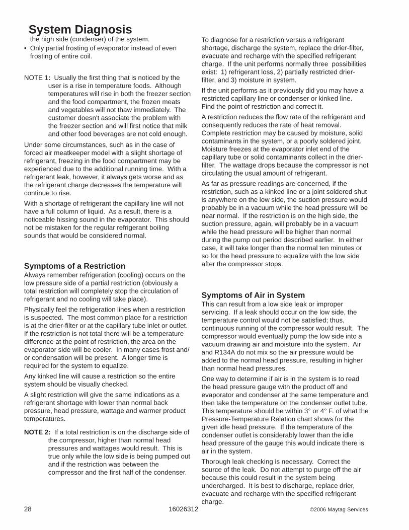
the high side (condenser) of the system.• Only partial frosting of evaporator instead of even
frosting of entire coil.
NOTE 1: Usually the first thing that is noticed by theuser is a rise in temperature foods. Althoughtemperatures will rise in both the freezer sectionand the food compartment, the frozen meatsand vegetables will not thaw immediately. Thecustomer doesn't associate the problem withthe freezer section and will first notice that milkand other food beverages are not cold enough.
Under some circumstances, such as in the case offorced air meatkeeper model with a slight shortage ofrefrigerant, freezing in the food compartment may beexperienced due to the additional running time. With arefrigerant leak, however, it always gets worse and asthe refrigerant charge decreases the temperature willcontinue to rise.With a shortage of refrigerant the capillary line will nothave a full column of liquid. As a result, there is anoticeable hissing sound in the evaporator. This shouldnot be mistaken for the regular refrigerant boilingsounds that would be considered normal.
Symptoms of a RestrictionAlways remember refrigeration (cooling) occurs on thelow pressure side of a partial restriction (obviously atotal restriction will completely stop the circulation ofrefrigerant and no cooling will take place).Physically feel the refrigeration lines when a restrictionis suspected. The most common place for a restrictionis at the drier-filter or at the capillary tube inlet or outlet.If the restriction is not total there will be a temperaturedifference at the point of restriction, the area on theevaporator side will be cooler. In many cases frost and/or condensation will be present. A longer time isrequired for the system to equalize.Any kinked line will cause a restriction so the entiresystem should be visually checked.A slight restriction will give the same indications as arefrigerant shortage with lower than normal backpressure, head pressure, wattage and warmer producttemperatures.
NOTE 2: If a total restriction is on the discharge side ofthe compressor, higher than normal headpressures and wattages would result. This istrue only while the low side is being pumped outand if the restriction was between thecompressor and the first half of the condenser.
To diagnose for a restriction versus a refrigerantshortage, discharge the system, replace the drier-filter,evacuate and recharge with the specified refrigerantcharge. If the unit performs normally three possibilitiesexist: 1) refrigerant loss, 2) partially restricted drier-filter, and 3) moisture in system.If the unit performs as it previously did you may have arestricted capillary line or condenser or kinked line.Find the point of restriction and correct it.A restriction reduces the flow rate of the refrigerant andconsequently reduces the rate of heat removal.Complete restriction may be caused by moisture, solidcontaminants in the system, or a poorly soldered joint.Moisture freezes at the evaporator inlet end of thecapillary tube or solid contaminants collect in the drier-filter. The wattage drops because the compressor is notcirculating the usual amount of refrigerant.As far as pressure readings are concerned, if therestriction, such as a kinked line or a joint soldered shutis anywhere on the low side, the suction pressure wouldprobably be in a vacuum while the head pressure will benear normal. If the restriction is on the high side, thesuction pressure, again, will probably be in a vacuumwhile the head pressure will be higher than normalduring the pump out period described earlier. In eithercase, it will take longer than the normal ten minutes orso for the head pressure to equalize with the low sideafter the compressor stops.
Symptoms of Air in SystemThis can result from a low side leak or improperservicing. If a leak should occur on the low side, thetemperature control would not be satisfied; thus,continuous running of the compressor would result. Thecompressor would eventually pump the low side into avacuum drawing air and moisture into the system. Airand R134A do not mix so the air pressure would beadded to the normal head pressure, resulting in higherthan normal head pressures.One way to determine if air is in the system is to readthe head pressure gauge with the product off andevaporator and condenser at the same temperature andthen take the temperature on the condenser outlet tube.This temperature should be within 3° or 4° F. of what thePressure-Temperature Relation chart shows for thegiven idle head pressure. If the temperature of thecondenser outlet is considerably lower than the idlehead pressure of the gauge this would indicate there isair in the system.Thorough leak checking is necessary. Correct thesource of the leak. Do not attempt to purge off the airbecause this could result in the system beingundercharged. It is best to discharge, replace drier,evacuate and recharge with the specified refrigerantcharge.
System Diagnosis
©2006 Maytag Services 16026312 29
Symptoms of Low or High AmbientTemperature InstallationLower ambient air temperature reduces the condensingtemperature and therefore reduces the temperature ofthe liquid entering the evaporator. The increase inrefrigeration effect due to operation in a lower ambientresults in a decrease in power consumption and runtime. At lower ambients there is a reduction in cabinetheat leak which is partially responsibile for lower powerconsumption and run time.An increase in refrigeration effect cannot be expectedbelow a certain minimum ambient temperature. Thistemperature varies with the type and design of theproduct.Generally speaking, ambient temperatures cannot belower than 60° F. without affecting operating efficiency.Conversely, the higher the ambient temperature thehigher the head pressure must be to raise the high siderefrigerant temperature above that of the condensingmedium. Therefore, head pressure will be higher as theambient temperature raises. Refrigerators installed inambient temperatures lower than 60° F. will not performas well because the pressures within the system aregenerally reduced and unbalanced. This means that thelower head pressure forces less liquid refrigerantthrough the capillary line. The result is the symptoms ofa refrigerant shortage. The lower the ambienttemperature the more pronounced this conditionbecomes.When a point where the ambient temperature is belowthe cut-in of the Temperature Control is reached, thecompressor won't run.The drain traps will freeze in ambient temperatures of32° F.Heat LoadA greater heat load can result from the addition of morethan normal supply of foods, such as after doing theweekly shopping. Other items contributing to anadditional heat load would be excessive door openings,poor door sealing, interior light remaining on, etc.An increase in heat being absorbed by the refrigerant inthe evaporator will affect the temperature and pressureof the gas returning to the compressor. Compartmenttemperatures, power consumption, discharge, andsuction pressures are all affected by heat load.Pressures will be higher than normal under heavy heatload.


Form No. A/02/0 6 Part No. 12828139 www.amana.com Litho USA
®
RefrigeratorUse & Care GuideImportant Safety Instructions ........................ 1-2
Quick Reference Guide........................................ 3
Installation ......................................................... 4-9
Using the Controls ....................................... 10-11
Ice And Water ................................................12-13
Water Filter ..................................................... 14-15
Fresh Food Features..................................... 16-17
Freezer Features ................................................. 18
Food Stor age T ips ........................................ 19-21
Car e and Cleaning ....................................... 22-25
Operating Sounds............................................... 26
Troubleshooting ............................................ 27-30
Ice & Water in French Door
1
Important Safety Instructions
WARNING – Hazards or unsafe practices whichCOULD result in severe personal injury or death.
WARNING
DANGER – Immediate hazards which WILL resultin severe personal injury or death.
DANGER
CAUTION – Hazards or unsafe practices which COULDresult in minor personal injury or property damage.
CAUTION
What You Need to Know AboutSafety InstructionsWarning and Important Safety Instructions appearing inthis guide are not meant to cover all possibleconditions and situations that may occur. Commonsense, caution and care must be exercised wheninstalling, maintaining or operating appliance.
Always contact the manufacturer about problems orconditions you do not understand.
Recognize Safety Symbols, Words,Labels
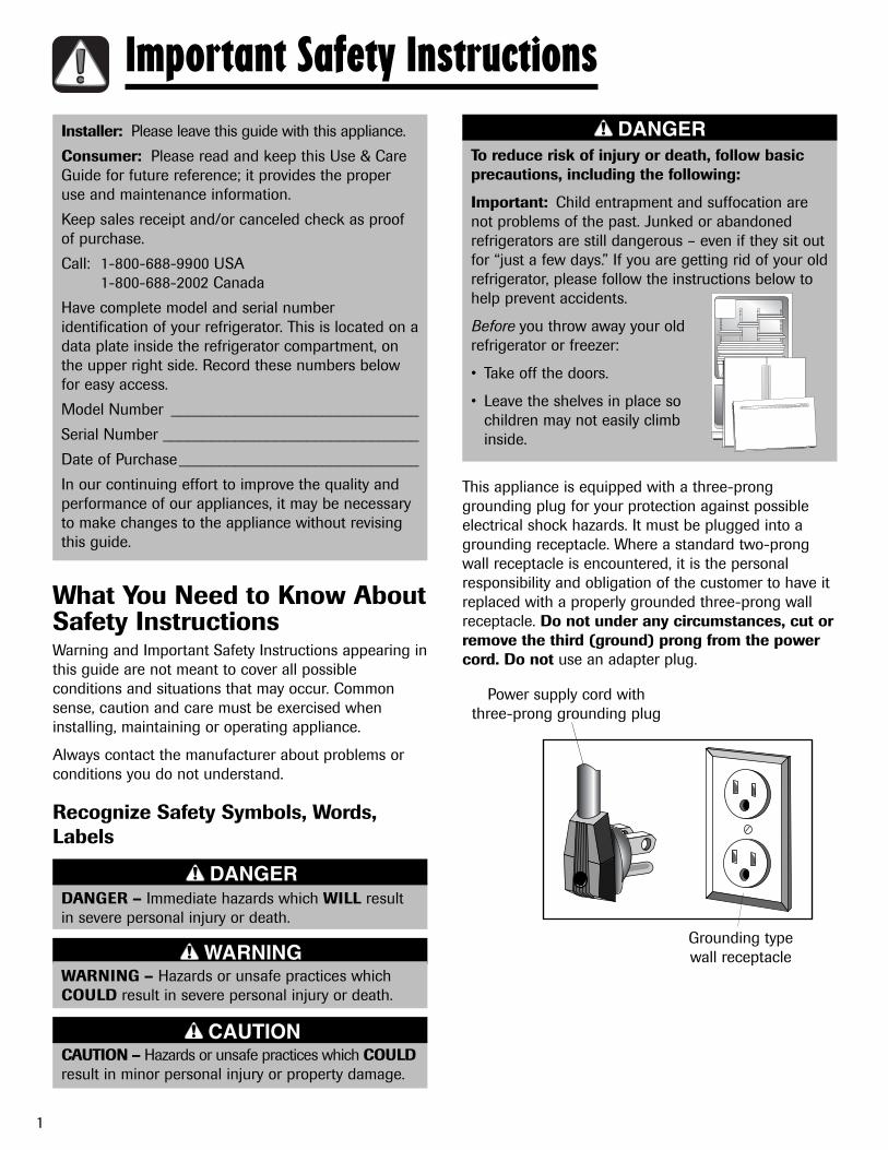
This appliance is equipped with a three-pronggrounding plug for your protection against possibleelectrical shock hazards. It must be plugged into agrounding receptacle. Where a standard two-prongwall receptacle is encountered, it is the personalresponsibility and obligation of the customer to have itreplaced with a properly grounded three-prong wallreceptacle. Do not under any circumstances, cut orremove the third (ground) prong from the powercord. Do not use an adapter plug.
Power supply cord with three-prong grounding plug
Grounding typewall receptacle
To reduce risk of injury or death, follow basicprecautions, including the following:
Important: Child entrapment and suffocation arenot problems of the past. Junked or abandonedrefrigerators are still dangerous – even if they sit outfor “just a few days.” If you are getting rid of your oldrefrigerator, please follow the instructions below tohelp prevent accidents.
Before you throw away your oldrefrigerator or freezer:
• Take off the doors.
• Leave the shelves in place sochildren may not easily climbinside.
DANGERInstaller: Please leave this guide with this appliance.
Consumer: Please read and keep this Use & CareGuide for future reference; it provides the properuse and maintenance information.
Keep sales receipt and/or canceled check as proofof purchase.
Call: 1-800-688-9900 USA1-800-688-2002 Canada
Have complete model and serial numberidentification of your refrigerator. This is located on adata plate inside the refrigerator compartment, onthe upper right side. Record these numbers belowfor easy access.
Model Number _______________________________
Serial Number ________________________________
Date of Purchase______________________________
In our continuing effort to improve the quality andperformance of our appliances, it may be necessaryto make changes to the appliance without revisingthis guide.

To reduce risk of fire, electric shock, seriousinjury or death when using your refrigerator,follow these basic precautions, including thefollowing:
1. Read all instructions before using the refrigerator.2. Observe all local codes and ordinances.3. Be sure to follow grounding instructions.4. Check with a qualified electrician if you are not
sure this appliance is properly grounded.5. Do not ground to a gas line.6. Do not ground to a cold-water pipe.7. Refrigerator is designed to operate on a separate
115 volt, 15 amp., 60 cycle line.8. Do not modify plug on power cord. If plug does
not fit electrical outlet, have proper outlet installedby a qualified electrician.
9. Do not use a two-prong adapter, extension cordor power strip.
10. Do not remove warning tag from power cord.11. Do not tamper with refrigerator controls.12. Do not service or replace any part of refrigerator
unless specifically recommended in Use and CareGuide or published user-repair instructions.Do not attempt service if instructions are notunderstood or if they are beyond personal skilllevel.
13. Always disconnect refrigerator from electricalsupply before attempting any service. Disconnectpower cord by grasping the plug, not the cord.
14. Install refrigerator according to InstallationInstructions. All connections for water, electricalpower and grounding must comply with localcodes and be made by licensed personnel whenrequired.
15. Keep your refrigerator in good condition. Bumpingor dropping refrigerator can damage refrigeratoror cause refrigerator to malfunction or leak. Ifdamage occurs, have refrigerator checked byqualified service technician.
16. Replace worn power cords and/or loose plugs.17. Always read and follow manufacturer’s storage
and ideal environment instructions for items beingstored in refrigerator.
18. Your refrigerator should not be operated in thepresence of explosive fumes.
19. Children should not climb, hang or stand on anypart of the refrigerator.
20. Clean up spills or water leakage associated withwater installation.
2
Important Safety Instructions
SAVE THESE INSTRUCTIONS
WARNING

3
Quick Reference GuideA
B
C
D
E F G H I
J
Quick Reference Guide
See pages 10-11 for more information on controls.
Use to control the temperature in the refrigerator and freezer compartments. Temperaturesare preset at the factory at 38° F (3° C) in the refrigerator compartment and 0° F (-17° C) inthe freezer compartment.Use to quickly drop compartment temperatures to minimum settings.To activate: press pad.To deactivate: press pad again.Senses light level within the room.
Use as a reminder to order or replace the filter. Press and hold the pad for three secondsto turn off lights.Use to lock all functions.To activate: press until green light illuminates. To deactivate: press and hold the pad for three seconds until green light turns off.Use to select water.
Use to fill large items that will not fit in dispenser area. Push the pad to use. To dispenseice and water simultaniously, choose Cube mode, then press container against dispenserpad while pressing the Front Fill pad.Use to select ice.Use to activate or deactivate the light. Press pad once for Auto, twice for Continuous orthree times to deactivate.Indicates the door has been left open. Close the door or press the Door Alarm pad todeactivate the feature.
A
B
C
D
E
F
G
HI
J
Temperature Control
Max Cool
Light Sensor
Reset Filter
Lock/Unlock
Water
Front Fill
Cube
Light
Door Alarm

4
Materials Needed:
• 3⁄8” hex head driver
• Carpenter’s level.
1. Remove toe grille.
• Grasp firmly and pull outward to unclip.
2. Using hex head driver, turn the front adjustmentscrews (A) on each side to raise or lower the frontof the refrigerator (see illustration below).
3. Using the hex head driver, turn each of theseadjustment screws (B) to raise or lower the rear ofthe refrigerator.
4. Using a carpenter’s level, make sure front ofrefrigerator is 1⁄4” (6 mm) or approximately 1⁄2 bubblehigher than back of refrigerator and that therefrigerator is level from side to side.
5. Turn stabilizing legs (C) clockwise until firmlyagainst floor.
6. Turn adjustment screws (A) counterclockwise toallow the full weight of the refrigerator to rest onthe stabilizing legs.
7. Replace the toe grille.
• Align the toe grille mounting clips with the lowercabinet slots.
• Push the toe grille firmly until it snaps into place.
InstallationYour refrigerator was packed carefully for shipment.Remove and discard shelf packaging and tape. Do notremove the serial plate.
Location• Do not install refrigerator near oven, radiator or other
heat source. If not possible, shield refrigerator withcabinet material (contact a qualified contractor).
• Do not install where temperature falls below 55° F (13° C) or rises above 110° F (43° C). Malfunction mayoccur at this temperature.
• Refrigerator is designed for indoor householdapplication only.
Measuring the OpeningWhen installing your refrigerator, measure carefully.Allow 1⁄2” space at top and 1⁄2” space behind the machinecompartment cover (located in the rear) for proper aircirculation.
Subflooring or floor coverings (i.e. carpet, tile, woodfloors, rugs) may make your opening smaller thananticipated.
Some clearance may be gained by using the levelingprocedure under Leveling.
Important: If refrigerator is to be installed into a recesswhere the top of the refrigerator is completely covered,use distance from floor to top of hinge cap to verifyproper clearance.
Transporting Your Refrigerator• NEVER transport refrigerator on its side. If an upright
position is not possible, lay refrigerator on its back.Allow refrigerator to sit upright for approximately 30minutes before plugging it in to assure oil returns tothe compressor. Plugging the refrigerator inimmediately may cause damage to internal parts.
• Use an appliance dolly when moving refrigerator.ALWAYS truck refrigerator from its side orback–NEVER from its front.
• Protect outside finish of refrigerator during transportby wrapping cabinet in blankets or inserting paddingbetween the refrigerator and dolly.
• Secure refrigerator to dolly firmly with straps orbungee cords. Thread straps through handles whenpossible. Do not over-tighten. Over-tighteningrestraints may dent or damage outside finish.
Leveling
To protect property and refrigerator fromdamage, observe the following:
• Protect vinyl or other flooring with cardboard, rugs,or other protective material.
• Do not use power tools when performing levelingprocedure.
CAUTION
To enhance the appearance and maintain performance,the refrigerator should be level.
Notes:• Complete any required water supply connection
before leveling.
• Some models only have adjustment screws “A”.
C C
A B AB

5
Installation
To avoid electrical shock which can causesevere personal injury or death, observe thefollowing:
• Disconnect power to refrigerator before removingdoors or drawer. Connect refrigerator door wireharness and power only after replacing doors ordrawer.
WARNING
To avoid damage to walls and flooring, protect vinylor other flooring with cardboard, rugs or otherprotective material. Monitor water connection for 24hours. Correct leaks if necessary.
CAUTION
Door and Drawer RemovalSome installations require door/drawer removal totransport the refrigerator to its final location.
1. Unplug power cord from power source.
2. Remove toe grille (see page 4).
3. Remove top hinge coverfrom right side refrigeratordoor by removing Phillipsscrews. Retain screw andcover for later use.
4. Unscrew 5⁄16” hex headscrews from top hinge toremove hinge and retainall screws for later use.
5. Lift right siderefrigerator door fromcenter hinge pin.Remove door closurefrom center hinge pinon the right side andretain for later use.
rightsidedoorclosure
Note: For refrigerators in operation, shut off waterbefore removing water line from the door.
6. Remove top hinge coverfrom left side refrigeratordoor by removing Phillipsscrews. Retain screwsand cover for later use.
7. Disconnect wire harnesson top left side ofrefrigerator door tophinge. Release connectorby pressing junctionpoint with a flat bladescrewdriver orfingernail.
8. Disconnect water line.Hold “tabbed” sectionof waterline whilerotating the blacklocking collar clockwiseand slide back.
9. Unscrew 5⁄16” hex headscrews from top hingeto remove hinge; retain forlater use.
10. Lift left side refrigerator door,along with top hinge, fromcenter hinge pin.
11. Remove center hinge pinwith a 5⁄16” hex head driverand retain hinge pin for lateruse.
12. Remove Phillipsscrews to removeright and left hinges;retain all screws forlater use.
13. Remove bothstabilizing bracketswith 3⁄8” hex headdriver; retain screwsfor later use.
Tabs
Connector

6
InstallationPullout Freezer Drawer
To avoid electrical shock which can cause severepersonal injury or death, disconnect power torefrigerator before removing doors. After replacingdoors, connect power.
WARNING
To avoid possible injury, product, or propertydamage, you will need two people to perform thefollowing instructions. Important: Always unloadfood in freezer trays before removing trays.
CAUTION
3. Remove Phillips screws fromeach of the drawer slides.
Door Reinstallation1. Install hinge assemblies:
• Install center hinge withPhillips screws.
2. Place hinge side of refrigeratordoor on center hinge pin.
• Install top hinge with 5⁄16” hex head screws.
3. While holding refrigerator door upright, tightendown top hinge with 5⁄16” hex head driver.
4. Reconnect connector.
5. Connect the waterlinetubes firmly by pushing onewaterline inside the other.
6. Slide the black lockingcollar fully forward.
7. Hold tabbed section ofwaterline.
8. Rotate black locking collarcounterclockwise lockingwater lines in place. A“click” is heard ensuringwaterlines are correctlylocked in place. The “arrow”on the tabbed section shouldalign with the 2 bars on theblack locking collar.
9. Ensure the connection doesnot leak before installing theupper hinge cover.
10. Replace top hinge covers.
To Remove:
1. Pull drawer open to fullextension.
2. Slide freezer drawer forwardand lift straight out.
4. Lift top of drawer front tounhook the drawer from theslides.
5. Move drawer slides fully forward.
6. Lift out lower drawer assembly.
Connector
Tabs

7
Notes:• Select models have a
slight curve to the freezerhandle.
• For proper installation, besure handle is oriented as shown.
To Install:
1. Align door handle clipsto the studs attached tothe freezer door.
2. Ensure the large hole inthe mounting clip ispositioned to the righton both ends of thehandle.
Freezer Handle
Handles
Installation
5. Grasp the handle firmly andslide down.
Plastic HandleTo Remove:
1. Grasp the lower part of thehandle firmly, slide up, lift andremove from the surface.
4. Rotate the handle so that thehandle is flat against the door.
To Install:
1. Pull both rails out to fullextension.
2. While supporting doorfront, hook supports intoslots located on inside ofeach slide.
Note: All four drawer bracket supports must be inthe proper slots for the drawer to function properly(see inset for detail).
3. Lower door front into finalposition.
4. Replace and tighten Phillipsscrews that were removedfrom the drawer slides.
5. Install the lower assembly byaligning hooks of lowerdrawer assembly with rearrail on freezer drawer.
6. Replace freezer drawers.Align the large squarenotches on outside of thedrawer slides.
3. Ensure the large hole in themounting clip is positioned downon both ends of the handle.
DoorStud
Note: If not installed, the handle is located in theinterior of the fresh food compartment or attachedto the back of your refrigerator.
To Install:
1. The handles are to be oriented asshown.
2. Align door handle clip with thedoor studs.

8
Connecting the Water Supply
To reduce the risk of injury or death, followbasic precautions, including the following:
• Read all instructions before installing ice maker.
• Do not attempt installation if instructions are notunderstood or if they are beyond personal skilllevel.
• Observe all local codes and ordinances.
• Do not service ice maker unless specificallyrecommended in Use and Care Guide or publisheduser-repair instructions.
• Disconnect power to refrigerator before installingice maker.
• Water damage due to an improper waterconnection may cause mold/mildew growth. Cleanup spills or leakage immediately!
WARNING
To avoid property damage or possible injury,follow basic precautions, including thefollowing:
• Consult a plumber to connect 1⁄4” O.D. coppertubing to household plumbing to assurecompliance with local codes and ordinances.
• Confirm water pressure to water valve is between35 and 100 pounds per square inch, 20 poundsper square inch without filter.
• Do not use a self-piercing, or 3⁄16” saddle valve.Both reduce water flow and can become cloggedover time, and may cause leaks if repair isattempted.
• Tighten nuts by hand to prevent cross threading.Finish tightening nuts with pliers and wrenches.Do not over-tighten.
• Wait two to three hours before placing refrigeratorinto final position to check and correct any waterleaks. Recheck for leaks after 24 hours.
• Verify the copper tubing under the sleeve issmooth and free from defects. Do not reuse anold sleeve.
CAUTION
Installation3. Rotate the handle so that the handle is flat against
the door.
4. Grasp the handle firmly and slide handle to theright and remove from surface.
To Remove:
1. With both hands, firmly grasp the handle towardthe right side.
2. Slide toward the left, lift and remove from thesurface.
To Remove:
• Loosen set screws inhandle using 3⁄32” Allenwrench.
• Repeat the procedure onall screws.
To Replace:
• Align handle with themounting posts.
• Fully tighten all setscrews to secure handlein place.
Metal Handle
Materials Needed:
• 3⁄32” Allen wrench
• Gloves to protect hands
Note: Metal handles can scratch doors.

9
1. Create service loop with coppertubing (minimum 2’diameter). Avoid kinks inthe copper tubing whenbending it into a serviceloop. Do not use plastictubing.
InstallationMaterials Needed:
• 1⁄4” outer diameter flexible copper tubing • Shut-off valve (requires a 1⁄4” hole to be drilled into
water supply line before valve attachment)• Adjustable wrenches (2)• 1⁄4” hex nut driver
Notes:• Use only copper tubing for installation. Plastic is
less durable and can cause damage.
• Add 8’ to tubing length needed to reach watersupply for creation of service loop.
2’ diameterminimum
2. Remove plastic cap from water valve inlet port.
3. Place brass nut (A) and sleeve (B)on copper tube end as illustrated.Reminder: Do not use an oldsleeve. The nut and sleeve areprovided in the Use and Care packet.
A
B
4. Place end of coppertubing into water valveinlet port.
5. Slide brass nut oversleeve and screw nut intoinlet port. Tighten nutwith wrench.
(1) Place adjustablewrench on nut attachedto plastic waterline andmaintain position.
(2) Using secondadjustable wrench turn the upper nut clockwise andfully tighten while holding the lower nut in place.
6. Pull on tubing to confirmconnection is secure. Connecttubing to frame with watertubing clamp (C). Slidewaterline into retainer, then turnon water supply. Check forleaks and correct if necessary.Continue to observe the watersupply connection for two tothree hours prior to moving therefrigerator to its permanent location.
7. Monitor water connection for 24 hours. Correctleaks, if necessary.
C
Important: Do not over-tighten. Cross threading mayoccur.
Opening and Closing YourFresh Food DoorsYour new refrigerator isuniquely designed with twofresh food doors. Either doorcan be opened or closedindependently of one another.
For proper usage and toavoid possible damage,always ensure the verticalhinged section (on the leftfresh food door) remainsfolded inward before closingboth doors. When both doorsare closed, the hinged sectionautomatically forms a seal between the two doors.
When the left door is opened, the vertical hingedsection automatically folds inward so that is is out ofthe way.
To avoid electrical shock which can cause severepersonal injury or death, DO NOT attempt toremove the vertical hinged section from the freshfood section.
WARNING
To avoid possible product damage, ALWAYS verifythat the vertical hinged section is folded againstthe edge of the door prior to closing.
CAUTION
VerticalHingedSection
2’
WaterlineRetainer
1
2
WaterlineSupply
Retainer

10
Temperature Control Guide
Refrigerator too cold
Refrigerator too warm
Freezer too cold
Freezer too warm
Turn refrigerator off
Using the Controls
Initial Temperature SettingTemperatures are preset at the factory at 38° F (3° C)in the fresh food compartment and 0° F (-18° C) in thefreezer compartment.
Adjusting the Control24 hours after adding food, you may decide that one orboth compartments should be colder or warmer. If so,adjust the control as indicated in the TemperatureControl Guide below.
• Do not change either control more than one degreeat a time. Allow temperature to stabilize for 24 hoursbefore making a new temperature adjustment.
Set the Refrigerator controlto next higher number bypressing the pad.
Set the Refrigerator controlto next lower number bypressing the pad.
Set the Freezer control tonext higher number bypressing the pad.
Set the Freezer control tonext lower number bypressing the pad.
Press the Freezer paduntil “OFF” appears in thedisplay. Press the ineither the freezer orrefrigerator section to turnback on.
Front Fill Button (select models)
The Front Fill Button works independently ofthe dispenser controls, providing an up-frontalternative to the dispenser pad fordispensing water. This feature is convenient for fillinglarge items that will not fit into the dispenser area (i.e.sport bottles, pitchers, large pans, coffee pots). Thisfeature allows added convenience of dispensing iceand water simultaneously. To use, choose Cube modefrom dispenser control panel. Press container againstdispenser pad while pressing the Front Fill button.
Water Filter Status Indicator Light
When a water filter has been installed in therefrigerator, the yellow Order light willilluminate when 90 percent used OR 11months have elapsed since the filter has beeninstalled.
The red Replace light will illuminate when the ratedvolume of water has passed through the filter OR 12months have elapsed since the filter was installed. Anew filter should be installed immediately when theReplace light is illuminated.
After replacing the filter, press and hold the Reset Filterpad for three seconds. The Order and Replace lightswill go off.
Light
The Light feature can be used to providelight to the dispenser area. The light featureis automatically activated and the indicatorlight illuminates. There are two methods available forlighting the dispenser - Auto and Continous.
The Auto light function activates the dispenser light athalf-power when the light sensor detects that the lightlevels in the room are low.
The Continuous light function provides light untildeactivated. The On indicator light will illuminate.
To Activate Auto Light:
Press the Light pad once. The Auto indicator willilluminate.
Cont.

11
• Activate the Sabbath Mode.To access the User Preferences menu, press and holdthe Door Alarm pad for three seconds. When in theUser Preferences mode, a short title for the feature willappear in the Freezer temperature display and thefeature status will appear in the Refrigerator display. 1. Use the Freezer and control to scroll
through the features. 2. When the desired feature is displayed, use the
Refrigerator and control to change thestatus.
3. When changes are complete, press the Door Alarmpad for three seconds OR close the Refrigeratordoor.
Temperature Display (F_C)
Change the display to show temperatures in degreesFahrenheit or degrees Celsius.
Alarm (AL)
When the Alarm mode is off, all audible alarms will bedisabled until the feature is turned on.
Auto Light Level Selection (LL)
This setting adjusts the light level at which thedispenser light will illuminate when the sensor detectsthat the light levels in the room are low. Setting 1 isthe darkest light level setting, setting 9 is the brightestlight level setting. Important: The Auto Light must beactivated on the ice and water dispenser control totake advantage of this option.
Sabbath Mode (SAb)
When the Sabbath Mode is on, all control lights,interior lights, and the night light will be disabled untilthe feature is turned off. Press the Door Alarm padfor three seconds to restore the lights.
Warm Cabinet SurfacesAt times, the front of the refrigerator cabinet may bewarm to the touch. This is a normal occurrence thathelps prevent moisture from condensing on thecabinet. This condition will be more noticeable whenthe refrigerator is first started, during hot weather andafter excessive or lengthy door openings.
Using the ControlsTo Activate Continuous Light:
Press Light pad again. The On indicator light willilluminate.
To Deactivate Auto or Continuous Light:
Press the Light pad a third time. This will turn off thedispenser and indicator light.
Door Alarm
The Door Alarm feature will alert you when oneof the doors has been left open forapproximately three minutes. When this happens, theDoor Alarm light will flash and an audible alarm willsound.
To Activate:
Press the Door Alarm pad once. The Door Alarmindicator light will illuminate.
To Deactivate:
Press the Door Alarm pad once. The indicator light willgo off.
To Turn Off the Audible Alarm:
Press the Door Alarm pad once or close the door.
Max Cool
The Max Cool feature is automaticallyactivated and the indicator light illuminates.This feature provides the ability to cool down therefrigerator and freezer after extended door openingsor when loading either compartment with warm food.This feature causes the refrigerator and freezertemperatures to drop to the minimum seetings on thecontrol. Important: When the Max Cool feature is inoperation, the and pads for the Refrigeratorand Freezer controls will not operate.
To Activate:
Press the Max Cool pad once. The Max Cool indicatorlight will illuminate.
To Deactivate:
Press the Max Cool pad once. The indicator light willgo off.
Max Cool will deactivate automatically after 2 hours.
User PreferencesAccess the User Preferences menu to:• Change the temperature display from °F to °C.• Enable or disable audible alarms.• Adjust the light level at which the Dispenser Auto
Light will illuminate when this feature is activated onthe ice and water dispenser.
Notes:• Dispenser light will not activate during dispensing
while in Sabbath Mode.
• If the power fails, the control will remain inSabbath Mode when power returns.

12
Dispenser Lock/Unlock
The Dispenser Lock/Unlock prevents iceor water from being dispensed.
To Lock Dispenser:
• Press and hold the Lock/Unlock button for threeseconds. A green indicator light above the button willilluminate when the dispenser is locked.
To Unlock Dispenser:
• Hold the Lock/Unlock button for three seconds. Thegreen indicator light above will go out.
Ice and Water
Ice and Water DispenserTo Use DispenserPaddle:
• Choose Water selection from dispenser control panel.
• Press a sturdy, wide-mouthed container against dispenser paddle.
• Release pressure on dispenser paddle to stop water dispensing. A smallamount of water may continue to dispense andcollect in dispenser tray. Large spills should be wiped dry.
Removable Tray
The removable tray at the bottom of the dispenser areais designed to collect small spills and may be easilyremoved for cleaning and emptying purposes.
Important: Removable tray does not drain. Do notallow tray to overflow. If it does, remove tray and wipeup overflow.
Notes: If dispenser is active for more than fiveminutes, an automatic lock out sensor will shutdown power to dispenser area. See DispenserLock/Unlock for unlocking information.
Note: During initial use of water dispenser andice maker, there will be a one to two minute delaywhile water tank fills before water dispenses or iceis made. Discard first 10-14 glasses of water afterinitially connecting refrigerator to household watersupply. Additional flushing may be required insome households where water is of poor quality.
To Dispense Ice and Water:
• Select Water, or Cube ice mode by pushing button on dispenser control panel. A green light above button indicates mode selection.
• Press container against dispenser paddle. When dispensing ice, hold container as close to chute as possible to reduce spraying.
Water Cube
DispenserPaddle
Removable Tray
Automatic Ice MakerConnect the ice maker to thewater supply as instructed onpages 8-9. Proper waterflow and a level refrigeratorare essential for optimalice maker performance.
Ice Storage BinThe ice storage bin islocated below theautomatic ice maker in theupper left side enclosureof the fresh foodcompartment.
To Remove:
• Depress the button on the lower right ofthe ice storage bin to release from the enclosure.Continue pulling until resistance is felt. Lift up frontof ice bin and remove. Press the switch on the frontof the ice maker to turn the ice maker off.
Important: Do not remove ice storage bin withoutpressing ice maker switch to OFF. Removing icestorage bin while ON could result in ice falling into theice storage bin enclosure, blocking the dispenser anddisabling the bin from being locked into properposition.
ON/OFFswitch
Note: Access to the ice storage bin will be limitedwith the left fresh food door opened at 90 degrees.Move cabinet forward to enable door to opensufficiently for ice storage bin access.
To Install:
Important: Ice bin must belocked in place for proper icedispensing. If necessary, turnauger driver behind ice bincounterclockwise to properly alignice bin with auger driver.
Cont.
Auger Driver

13
Ice and Water
Operating Instructions• Confirm ice bin is in place.
• After freezer section reaches between 0° to 2° F (-18°to -17° C), ice maker fills with water and beginsoperating. You will have a complete harvest of iceapproximately every hour.
• Allow approximately 3 to 6 hours after installation toreceive first harvest of ice.
• Discard ice created within the first 12 hours ofoperation to verify system is flushed of impurities.
• Stop ice production by pressing the ON/OFF switchlocated on the front of the ice maker.
• The first one or two batches will probably containundersized and irregular cubes because of air in thesupply line.
• When the ice cubes are ejected it is normal forseveral cubes to be joined together at the ends. Theycan easily be broken apart. The ice maker willcontinue to make ice until the supply of ice cubesraises the ice maker arm, shutting the ice maker off.
• Certain sounds may accompany the various cycles ofthe ice maker. The motor may have a slight hum, thecubes will rattle as they fall into an empty storagepan and the water valve may click or “buzz”occasionally.
• If the ice is not used frequently, the ice cubes willbecome cloudy, shrink, stick together and taste stale.Empty the ice storage bin periodically and wash it inlukewarm water. Be sure to dry the bin thoroughlybefore replacing it.
• Beverages and foods should not be placed in theice storage bin for quick chilling. These items cancause the ice maker to malfunction.
• Press the switch on the ice maker front to OFF whenthe water supply is to be shut off for several hours.
To avoid personal injury or property damage,observe the following:
• Do not place fingers or hands on the automaticice making mechanism while the refrigerator isplugged in. This will help protect you from possibleinjury. It will also prevent interference with movingparts of the ejector mechanism and the heatingelement that releases the cubes.
• Under certain rare circumstances, ice cubes maybe discolored, usually appearing with a green-bluish hue. The cause of this unusual discolorationcan be a combination of factors such as certaincharacteristics of local waters, householdplumbing and the accumulation of copper salts inan inactive water supply line which feeds the icemaker. Continued consumption of such discoloredice cubes may be injurious to health. If suchdiscoloration is observed, discard the ice cubesand contact your dealer to purchase and install awater line filter.
• Water damage due to improper water connectionmay cause mold/mildew growth.
• Clean up water and ice spills to avoid personalinjury and to prevent mold/mildew growth.
• Do not dispense ice directly into thin glass, finechina or delicate crystal.
WARNING• Press the switch ON to activate ice maker. Slide bininto guide rails located on either side of theenclosure. Push the ice bin in until resistance is felt.Raise the front slightly and push the ice bincompletely in. An audible “click” is heard whenthe ice bin is located correctly.

14
Water Filter Water Filter Removaland Installation
To avoid serious illness or death, do not userefrigerator where water is unsafe or of unknownquality without adequate disinfection before or afteruse of filter.
WARNING
After installing a new water filter, alwaysdispense water for two minutes beforeremoving the filter for any reason. Air trapped insystem may cause water and cartridge to eject.Use caution when removing.
• The bypass cap does not filter water. Be sure tohave replacement cartridge available when filterchange is required.
• If water filtration system has been allowed tofreeze, replace filter cartridge.
• If system has not been used for several months, orwater has an unpleasant taste or odor, flushsystem by dispensing water for two to threeminutes. If unpleasant taste or odor persists,change filter cartridge.
CAUTION
Initial InstallationThe water filter islocated in the upperright-hand corner of thefresh foodcompartment.
1. Remove blue bypasscap and retain forlater use.
2. Remove sealinglabel from end offilter and insert intofilter head.
3. Rotate gentlyclockwise until filterstops. Snap filtercover closed.
Replacing Water FilterImportant: Air trapped in system may causewater and cartridge to eject. Always dispensewater for at least 2 minutes before removing thefilter for any reason. Use caution when removing.
1. Turn filter counterclockwise until it releases fromfilter head.
2. Drain water from filter into sink, and dispose innormal household trash.
3. Wipe up excess water in filter cover and continuewith Initial Installation, steps 2 through 3.
The filter should be changed at least every 12 months.
Important: Condition of water and amount useddetermines life span of water filter cartridge. If wateruse is high, or if water is of poor quality, replacementmay need to take place more often.
To purchase a replacement water filter cartridge,contact your dealer or call 1-877-232-6771 USA or 1-800-688-8408 Canada.
The dispenser feature may be used without a waterfilter cartridge. If you choose this option, replace filterwith blue bypass cap.
State of CaliforniaDepartment of Health Services
Water Treatment DeviceCertificate Number
03 - 1583Date Issued: September 16, 2003
Date Revised: April 22, 2004
Trademark /Model Designation Replacement Elements
UKF8001AXX750 UKF8001AXX
469006-750 46 9006
67003523-750 67003523
Manufacturer: PentaPure Inc.
The water treatment device(s) listed on this certificate have met the testing requirements
pursuant to Section 116830 of the Health and Safety Code for the following health related
contaminant's:
Microbiological contaminant's and Turbidity Inorganic/Radiological contaminant'sCysts AsbestosTurbidity Lead
Mercury
Organic contaminant'sAtrazineLindaneBenzeneCarbofuranp-dichlorobenzeneToxaphene
Rated Service Capacity: 750 gal. Rated Service Flow: 0.78 gpm
Conditions of Certification:Do not use where water is microbiologically unsafe or with water of unknown quality, except thatsystems certified for cyst reduction may be used on disinfected waters that may contain filterablecysts.
Pull tab to remove

15
Water Filter System Specification and Performance Data Sheet Refrigerator Water Filter Cartridge Model UKF8001AXX
SpecificationsService Flow Rate (Maximum).............................................0.78 GPM (2.9 L/min)Rated Service Life UKF8001AXX-750 (Maximum)......750 gallons/2838 litersMaximum Operating Temperature .....................................100° F / 38° CMinimum Pressure Requirement........................................35 psi /241 kPAMinimum Operating Temperature ......................................33° F/1° CMaximum Operating Pressure.............................................120 psi /827 kPA
Performance Data
1000 Apollo RoadEagan, Minnesota 55121-2240
651.450.4913EPA EST #35917-MN-1
100834/B
The PuriClean® II retractable water filtration system uses aUKF8001AXX replacement cartridge. Timely replacementof filter cartridge is essential for performance satisfactionfrom this filtration system. Please refer to the applicablesection of your Use and Care Guide for general operation,maintenance requirements and troubleshooting.Suggested retail price of replacement water filter is $39.99.
This system has been tested according to ANSI/NSF 42 and53 for reduction of the substance listed above. Theconcentration of the indicated substances in water enteringthe system was reduced to a concentration less than orequal to the permissible limit for water leaving the system,as specified in ANSI/NSF 42 and 53.
General Use ConditionsRead this Performance Data Sheet and compare thecapabilities of this unit with your actual watertreatment needs.
DO NOT use this product where water is microbio-logically unsafe or of unknown quality withoutadequate disinfection before or after the system.System certified for cyst reduction may be used ondisinfected water that may contain filterable cysts.
USE ONLY WITH COLD WATER SUPPLY. CHECKFOR COMPLIANCE WITH THE STATE AND LOCALLAWS AND REGULATIONS.
* Tested using a flow rate of 0.78 gpm; pressure of 60 psig; pH of 7.5 + 0.5; temp. of68° + 5° F (20° + 3° C)
** Measurement in Particles /ml. Particles used were 0.5 - 1 microns
*** NTU - Nephelometric Turbidity UnitsStandard No. 42: Aesthetic EffectsTaste and Odor ReductionChlorine Taste & OdorMechanical Filtration UnitParticulate Reduction Class 1
Standard No. 53: Health EffectsChemical Reduction UnitLead, Atrazine, Lindane, Benzene,Carbofuran, p-Dichlorobenzene, Mercury& Toxaphene ReductionMechanical Filtration UnitCyst, Turbidity and Asbestos Reduction
Tested and certified by NSF International against ANSI/NSF Standards 42 & 53in models UKF8001AXX-750 for the reduction of:
Parameter
Chlorine
T & O
Particulate**
USEPA MCL
—
—
—
Standard No. 42: Aesthetic Effects
InfluentChallenge Concentration
2.0 mg/L ± 10%
—
at least 10,000 particles/ml
InfluentAverage
1.88 mg/L
—
5,700,000 #/ml
Average
<0.05136364 mg/L
—
30,583 #/ml
Maximum
0.06 mg/L
—
69,000 #/ml
Average
>97.26%
—
99.52%
Minimum
96.84%
—
98.94%
Min. RequiredReduction
50%
—
85%
Effluent % Reduction
USEPA MCL
1 NTU**
99.5% Reduction
99% Reduction
0.015 mg/L
0.015 mg/L
0.002 mg/L
0.002 mg/L
0.003 mg/L
0.005 mg/L
0.04 mg/L
0.075 mg/L
0.0002 mg/L
0.003 mg/L
Standard No. 53: Health Effects
InfluentChallenge Concentration
11 ± 1 NTU***
Minimum 50,000/L
107 108 fibers/L; fibers >10 micrometers in length
0.15 mg/L + 10%
0.15 mg/L + 10%
.006 mg/L ± 10%
.006 mg/L ± 10%
0.009 mg/L + 10%
0.015 mg/L ± 10%
0.08 mg/L ± 10%
.225 mg/L ± 10%
0.002 mg/L + 10%
0.015 ± 10%
InfluentAverage
10.7 NTU
166,500 #/L
155 MF/L
0.153 mg/L
0.150 mg/L
0.006 mg/L
0.006 mg/L
0.009 mg/L
0.014 mg/L
0.081 mg/L
0.208 mg/L
0.002 mg/L
0.015 mg/L
Average
0.31 NTU
<1 #/L
<1 MF/L
<.001 mg/L
<.001 mg/L
0.0003 mg/L
0.0008 mg/L
<0.002 mg/L
0.0006 mg/L
<0.001 mg/L
<0.0005 mg/L
0.000 mg/L
<0.001 mg/L
Maximum
.049 NTU
<1 #/L
<1 MF/L
<.001 mg/L
<.001 mg/L
0.0005 mg/L
0.0015 mg/L
0.002 mg/L
0.0011 mg/L
<0.001 mg/L
<0.0005 mg/L
<0.0001 mg/L
<0.001 mg/L
Average
97.09%
>99.99%
>99.99%
>99.35%
>99.33%
95.70%
86.22%
76.99%
95.71%
98.74%
99.76%
98.72%
92.97%
Minimum
95.20%
>99.99%
>99.99%
>99.29%
>99.29%
90.91%
75.93%
75.31%
92.14%
98.46%
99.74%
96.50%
91.67%
Min. RequiredReduction
0.5 NTU
>99.95%
99%
0.10 mg/L
0.10 mg/L
0.002 mg/L
0.002 mg/L
0.003 mg/L
0.005 mg/L
0.04 mg/L
0.075 mg/L
0.0002 mg/L
0.003 mg/L
Effluent % ReductionParameter
Turbidity
Cysts
Asbestos
Lead at pH 6.5
Lead at pH 8.5
Mercury at pH 6.5
Mercury at pH 8.5
Atrazine
Benzene
Carbofuran
p-Dichlorobenzene
Lindane
Toxaphene
TM

16
Fresh Food FeaturesShelves
To avoid personal injury or property damage,observe the following:
• Never attempt to adjust a shelf that is loaded withfood.
• Confirm shelf is secure before placing items onshelf.
• Handle tempered glass shelves carefully. Shelvesmay break suddenly if nicked, scratched, orexposed to sudden temperature change.
CAUTION
SpillsaverTM Glass ShelvesYour refrigerator has SpillsaverTM glass shelves. Theshelves have a spill retainer edge which allows foreasier clean up and some are equipped with a slideout feature. To slide out, grasp the front of the shelfand pull forward. Push in the shelf to return to theoriginal position.
To Remove a Shelf:
• Slightly tilt up the front and lift upthe rear of the shelf, then pull theshelf straight out.
To Lock the Shelf Into AnotherPosition:
• Tilt up the front edge of the shelf.
• Insert the hook into the desired frame openings andlet the shelf settle into place.
• Be sure the shelf is securely locked at the rear.
Door StorageDairy CenterThe dairy center providesconvenient door storage forspreadable items such as butterand margarine. This compartmentcan be moved to different locations to accommodatestorage needs. To use the dairy center, raise the cover.
To Remove:
• Raise the cover, push upward and pull out.
To Install:
• Slide the dairy center in and push down until firmlyseated in the door liner.
Door BucketsDoor buckets can be moved to meet storage needs.
To Remove:
• Slide bucket up and pull straight out.
To Install:
• Slide bucket in and push downuntil firmly seated in the door liner.
Crisper TopThe crisper top serves as the lower fresh food shelf.
To Remove the Crisper Top:
• Remove crisper drawers.
• Place hand under the frame to push up the glass. Liftglass out.
• Lift frame from refrigerator liner rails.
To Install:
• Replace frame in refrigerator liner rails.
• Carefully replace glass into frame.Note: For best results, keep the crisper drawerstightly closed.
To Remove:
• Pull drawer out to full extension. Tilt up front ofdrawer and pull straight out.
To Install:
• Insert drawer into frame rails and push back intoplace.
Crisper DrawersThe crisper drawers provide a higher humidityenvironment for fresh fruit and vegetable storage.
Controls
The crisper controls regulate the amount of humidity inthe crisper drawer. Slide the control toward the FRUITsetting for produce with outer skins. Slide the controltoward the VEGETABLES setting for leafy produce.

17
Chef’s PantryTM Drawer The Chef’s PantryTM drawer is a full-width drawer withadjustable temperature control. This drawer can beused for large party trays, deli items, beverages ormiscellaneousitems andfeatures adivider toorganize thedrawer intosections ifdesired.
There is atemperature control which adjusts the amount ofcold air allowed into the drawer. The control is locatedon the right side of the drawer, under the lid.
Set the control to the higher setting to provide anormal refrigerator temperature. Set the drawer on thelower setting when a temperature colder than themain refrigerator compartment is desired. Use thecoldest setting when storing meats.
Notes:• Cold air directed to the drawer can decrease
refrigerator temperature. Refrigerator control mayneed to be adjusted.
• Do not place leafy vegetables in the drawer.Colder temperatures could damage leafy produce.
Fresh Food FeaturesAccessoriesGrip Pads (select models)The grip pads prevent objects fromsliding in the door buckets. Grippads are removable and are top-rackdishwasher safe for easy cleaning.
Egg Tray (style may vary)The egg tray holds a “dozen-plus” eggs. It can beremoved to carry to a work area or to be washed.
Wine Trivet/Can RackThe wine trivet/can rack accessory fits in the Chef’sPantry™ drawer or on a shelf.
Bottles or cans can be laid crosswise, or a single bottlemay be laid in the center depression.
To Remove Drawer:
• Lift lid. Pull drawer out to full extension. Tilt up frontof drawer and pull straight out.
To Install Drawer:
• Push metal glide rails to the back of the refrigerator.Place drawer onto rails and slide drawer back until itfalls into place.
To Remove Divider:
• Pull drawer completely out and raise the front of thedivider to unhook it from the rear wall of the drawer,then lift drawer out.
To Install Divider:
• Hook back of divider over rear wall of drawer andlower into place.
FastGrabTM OrganizerThe vertical can rack is located in thefresh food section on the inside leftdoor. The can rack is designed to holdsix - 12oz. cans, 20oz. bottles, babybottles or yogurt containers individually.
Beverage ChillerThe Beverage Chiller keeps beveragesand other items cooler than the rest ofthe fresh food section. A cold air inletallows air from the freezer section to passinto the Beverage Chiller. The BeverageChiller control is located on the right wallof the fresh food compartment. Thecontrol adjusts the amount of cold airallowed into the Beverage Chiller. For acooler temperature in the BeverageChiller, slide the control down. TheBeverage Chiller can hold up totwo gallons of milk or two-2 literbottles of soda, for example.
To Remove:
• Slide bucket up and straight out. Firmly hold each side of the beverage chiller, lift up and away from the door.
To Install:
• Reverse above procedure.

18
Freezer Features
Note: See pages 6-7 for complete information onlower drawer and drawer removal.
To Remove:
• Pull upper drawer out to full extension and lift out toremove.
To Install:
• Slide upper drawer intofreezer. Make sure the largesquare holes along outer binalign with square knobs onfreezer drawer.
Freezer Bin Lower Freezer Drawer
19
Food Storage TipsFresh Food Storage• The fresh food compartment of a refrigerator should
be kept between 34°-40° F (1°-4° C) with anoptimum temperature of 37° F (3° C). To check thetemperature, place an appliance thermometer in aglass of water and place in the center of therefrigerator. Check after 24 hours. If the temperatureis above 40° F (4° C) adjust the controls as explainedon pages 10 and 11.
• Avoid overcrowding the refrigerator shelves. Thisreduces the circulation of air around the food andresults in uneven cooling.
Fruits and Vegetables• Storage in the crisper drawers traps humidity to help
preserve the fruit and vegetable quality for longertime periods (see page 16).
• Sort fruits and vegetables before storage and usebruised or soft items first. Discard those showingsigns of decay.
• Always wrap odorous foods such as onions andcabbage so the odor does not transfer to other foods.
• While vegetables need a certain amount of humidityto remain fresh, too much humidity can shortenstorage times (especially leafy vegetables). Drainvegetables well before storing.
• Wait to wash fresh produce until right before use.
Meat and Cheese• Storage in Chef’s PantryTM drawer helps preserve
quality for longer time periods.
• Raw meat and poultry should be wrapped securelyso leakage and contamination of other foods orsurfaces does not occur.
• Occasionally mold will develop on the surface ofhard cheeses (Swiss, Cheddar, Parmesan). Cut off atleast an inch around and below the moldy area. Keepyour knife or instrument out of the mold itself.Do not try to save individual cheese slices, softcheese, cottage cheese, cream, sour cream or yogurtwhen mold appears.
Dairy Food• For milk and cream, store in the Beverage Chiller
which is designed to maintain a lower temperaturefor optimum freshness and life.
• Most dairy foods such as milk, yogurt, sour creamand cottage cheese have freshness dates on theircartons for appropriate length of storage. Store thesefoods in the original carton and refrigerateimmediately after purchasing and after each use.
Frozen Food Storage• The freezer compartment of a refrigerator should be
kept at approximately 0° F (-18° C). To check thetemperature, place an appliance thermometerbetween the frozen packages and check after 24hours. If the temperature is above 0° F (-18° C),adjust the control as described on page 10.
• A freezer operates more efficiently when it is at leasttwo-thirds full.
Packaging Foods for Freezing• To minimize dehydration and quality deterioration use
aluminum foil, freezer wrap, freezer bags or airtightcontainers. Force as much air out of the packages aspossible and be sure they are tightly sealed. Trappedair can cause the food to dry out, change color anddevelop an off-flavor (freezer burn).
• Overwrap fresh meats and poultry with suitablefreezer wrap prior to freezing.
• Do not refreeze meat that has completely thawed.
Loading the Freezer• Avoid adding too much warm food to the Freezer at
one time. This overloads the Freezer, slows the rate offreezing and can raise the temperature of frozenfoods.
• Leave space between the packages so cold air cancirculate freely, allowing food to freeze as quickly aspossible.
Refer to the Food Storage Chart on pages 20 and 21 forapproximate storage times.

20
Food Storage TipsFood Storage ChartStorage times are approximate and may vary depending on type of packaging, storage temperature, and the qualityof the food when purchased.
FOODS
DAIRY PRODUCTS
Butter
Milk and cream
Cream cheese, cheese spread and cheese food
Cottage cheese
Sour cream
Hard cheese (Swiss, Cheddar and Parmesan)
EGGS
Eggs in the shell
Leftover yolks or whites
FRUITS Store in Crisper Drawer
Apples
Bananas
Pears, plums, avocados
Berries, cherries, apricots
Grapes
Citrus fruits
Pineapples, cut
REFRIGERATOR
1 month1 weekStore inTemperatureControlled BeverageChiller.
1 to 2 weeks
3 to 5 days
10 days
1 to 2 months
3 weeks
2 to 4 days
1 month
2 to 4 days
3 to 4 days
2 to 3 days
3 to 5 days
1 to 2 weeks
2 to 3 days
FREEZER
6 to 9 months
Not recommended
Not recommended
Not recommended
Not recommended
4 to 6 monthsMay becomecrumbly
Not recommended
9 to 12 months
8 months (cooked)
6 months(whole/peeled)
Not recommended
6 months
1 month (whole)
Not recommended
6 to 12 months
STORAGE TIPS
Wrap tightly or cover.
Check carton date. Close tightly.Do not return unused portions tooriginal container. Do not freezecream unless whipped.
Wrap tightly.
Store in original carton. Check carton date.
Store in original carton. Check carton date.
Wrap tightly. Cut off any mold.
Refrigerate small ends down.
For each cup of yolks to be frozen,add 1 tsp. sugar for use in sweet, or1 tsp. salt for non-sweet dishes.
May also store unripe or hard applesat 60° to 70° F (16° to 21° C).
Ripen at room temperature beforerefrigerating. Note: Bananas darkenwhen refrigerated.
Ripen at room temperature beforerefrigerating. Note: Avocados darkenwhen refrigerated.
Ripen at room temperature beforerefrigerating.
Ripen at room temperature beforerefrigerating.
May also store at 60° to 70° F (16° to21° C). If refrigerated, store uncovered.
Will not ripen after purchase. Use quickly.

21
Food Storage Tips
Sources: United States Department of Agriculture; Food Marketing Institute; Cooperative Extension Service, IowaState University
FOODS
VEGETABLES Store in Crisper Drawer
Asparagus
Brussels sprouts, broccoli, cauliflower, green peas, lima beans, onions, peppers
Cabbage, celery
Carrots, parsnips, beets and turnips
Lettuce
POULTRY and FISH Store in Chef’s PantryTM Drawer or Freezer
Chicken and Turkey, whole
Chicken and Turkey, pieces
Fish
MEATS Store in Chef’s PantryTM Drawer or Freezer
Bacon
Beef or lamb, ground
Beef or lamb, roast and steak
Ham, fully cooked, whole
half
slices
Luncheon meat
Pork, roast
Pork, chops
Sausage, ground
Sausage, smoked
Veal
Frankfurters
REFRIGERATOR
1 to 2 days
3 to 5 days
1 to 2 weeks
7 to 10 days
7 to 10 days
1 to 2 days
1 to 2 days
1 to 2 days
7 days
1 to 2 days
3 to 5 days
7 days
5 days
3 days
3 to 5 days
3 to 5 days
3 to 5 days
1 to 2 days
7 days
3 to 5 days
7 days
FREEZER
8 to 10 months
8 to 10 months
Not recommended
8 to 10 months
Not recommended
12 months
9 months
2 to 6 months
1 month
3 to 4 months
6 to 9 months
1 to 2 months
1 to 2 months
1 to 2 months
1 to 2 months
4 to 6 months
4 months
1 to 2 months
1 to 2 months
4 to 6 months
1 month
STORAGE TIPS
Do not wash before refrigerating.Store in crisper.
Wrap odorous foods. Leave peas in pods.
Wrap odorous foods and refrigeratein crisper.
Remove tops. Wrap odorous foodsand refrigerate in the crisper.
Keep in original packaging forrefrigeration. Place in the meat andcheese drawer. When freezing longerthan two weeks, overwrap withfreezer wrap.
Fresh meats can be kept in originalpackaging for refrigeration.
Place in the meat and cheese drawer.When freezing longer than twoweeks, overwrap with freezer wrap.
Unopened, vacuum-packed luncheonmeat may be kept up to two weeksin the meat and cheese drawer.
Processed meats should be tightlywrapped and stored in the meat andcheese drawer.

22
Care and Cleaning
To avoid electrical shock which can cause severepersonal injury or death, disconnect power torefrigerator before cleaning. After cleaning, connectpower.
WARNINGTo avoid personal injury or property damage,observe the following:
• Read and follow manufacturer’s directions for allcleaning products.
• Do not place buckets, shelves or accessories indishwasher. Cracking or warping of accessoriesmay result.
CAUTION
* To order, call 1-877-232-6771 USA or 1-800-688-8408 Canada.
Refrigerator Cleaning Chart
PART
Smooth or Textured PaintedDoors and Exterior (select models)Damage to finish due to improperuse of cleaning products or non-recommended products is not covered under this product’s warranty.
Cabinet Interior
Stainless Steel Doors and Exterior (select models)Important:Damage to stainless steel finish due to improper use of cleaning products or non-recommended products is not covered under this product’s warranty.
Door Gaskets and IceDispenser Chute
Condenser Coil Remove base grille to access.
Condenser Fan Outlet GrilleSee back of refrigerator.
Accessories Shelves, buckets, drawers, etc.
DO NOT USE
Abrasive or harsh cleanersAmmoniaChlorine bleachConcentrated detergentsor solventsMetal or plastic-textured scouring pads
Abrasive or harsh cleanersAmmoniaChlorine bleachConcentrated detergents orsolventsMetal or plastic-texturedscouring padsVinegar-based productsCitrus-based cleaners
DO
Use 4 tablespoons of baking soda dissolved in 1quart (1 liter) warm, soapy water.Rinse surfaces with clean, warm water and dryimmediately to avoid water spots.
Use warm, soapy water and a soft, clean cloth orsponge.Rinse surfaces with clean, warm water and dryimmediately to avoid water spots.To polish and help prevent fingerprints, follow withStainless Steel Magic Spray (part no. 20000008*).
Abrasive or harsh cleanersMetal or plastic-textured scouring pads
Anything other than a vacuumcleaner
A dishwasher
Use a vacuum cleaner hose nozzle.
Use a vacuum cleaner hose nozzle with brushattachment.
Follow removal and installation instructions fromappropriate feature section. Allow items to adjust to room temperature.Dilute mild detergent and use a soft, clean cloth orsponge for cleaning. Use a plastic bristle brush to get into crevices. Rinsesurfaces with clean, warm water.Dry glass and clear items immediately to avoid spots.
Use warm, soapy water and a soft, clean cloth orsponge.

23
Care and CleaningRemoving Odorsfrom Refrigerator
1. Remove all food and turn the refrigerator off.
2. Disconnect power to the refrigerator.
3. Clean the walls, floor, ceiling of cabinet interior,drawers, shelves and gaskets according to theinstructions on page 22.
4. Dilute mild detergent and brush solution intocrevices using a plastic bristle brush. Let stand for5 minutes. Rinse surfaces with warm water. Drysurfaces with a soft, clean cloth.
5. Wash and dry all bottles, containers and jars.Discard spoiled or expired items.
6. Wrap or store odor-causing foods in tightly sealedcontainers to prevent recurring odors.
7. Reconnect power to refrigerator and return food torefrigerator.
8. Allow the refrigerator to cool.
9. After 24 hours, check if odor has been eliminated.
If Odor is Still Present:
1. Remove drawers and place on top shelf ofrefrigerator.
2. Pack refrigerator and freezer sections – includingdoors – with crumpled sheets of black and whitenewspaper.
3. Place charcoal briquettes randomly on crumplednewspaper in both freezer and fresh foodcompartments.
4. Close doors and let stand 24 to 48 hours.
Energy Saving Tips• Avoid overcrowding refrigerator shelves.
Overcrowding reduces air circulation around foodand causes refrigerator to run longer.
• Avoid adding too much warm food to refrigerator atone time. This overloads compartments and slowsrate of cooling.
• Do not use aluminum foil, wax paper, or papertoweling as shelf liners. This decreases air flow andcauses refrigerator to run less efficiently.
• A freezer that is two-thirds full runs most efficiently.
• Locate refrigerator in coolest part of room. Avoidareas of direct sunlight, or near heating ducts,registers or other heat producing appliances. If this isnot possible, isolate exterior by using a section ofcabinet or an added layer of insulation.
• Clean door gaskets every three months according tocleaning instructions. This will assure that door sealsproperly and refrigerator runs efficiently.
• Take time to organize items in refrigerator to reducetime that door is open.
• Be sure your doors are closing securely by levelingrefrigerator according to the instructions on page 4.
• Clean condenser coils as indicated in the cleaninginstructions every three months. This will increaseenergy efficiency and cooling performance.
To avoid electrical shock which can cause severepersonal injury or death, disconnect power torefrigerator before cleaning. After cleaning,reconnect power.
WARNING
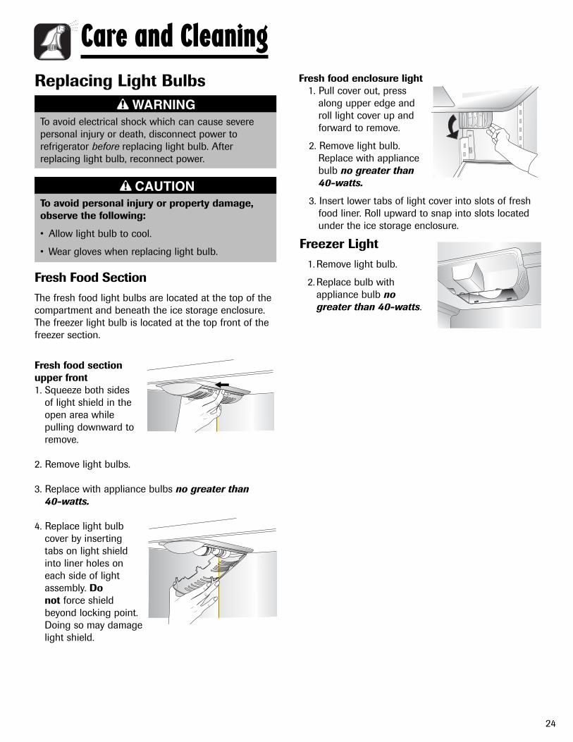
24
Care and Cleaning
To avoid electrical shock which can cause severepersonal injury or death, disconnect power torefrigerator before replacing light bulb. Afterreplacing light bulb, reconnect power.
WARNING
To avoid personal injury or property damage,observe the following:
• Allow light bulb to cool.
• Wear gloves when replacing light bulb.
CAUTION
Replacing Light Bulbs
Freezer Light 1. Remove light bulb.
2. Replace bulb withappliance bulb no greater than 40-watts.
Fresh Food Section The fresh food light bulbs are located at the top of thecompartment and beneath the ice storage enclosure.The freezer light bulb is located at the top front of thefreezer section.
Fresh food sectionupper front 1. Squeeze both sides
of light shield in the open area while pulling downward to remove.
2. Remove light bulbs.
3. Replace with appliance bulbs no greater than 40-watts.
4. Replace light bulb cover by inserting tabs on light shield into liner holes on each side of light assembly. Do not force shield beyond locking point. Doing so may damagelight shield.
Fresh food enclosure light1. Pull cover out, press
along upper edge and roll light cover up and forward to remove.
2. Remove light bulb. Replace with appliance bulb no greater than40-watts.
3. Insert lower tabs of light cover into slots of fresh food liner. Roll upward to snap into slots located under the ice storage enclosure.

25
Care and Cleaning
If there is any possibility that the temperature candrop below freezing where the refrigerator islocated, the water supply system (including thewater tank and the water valve) must be drained bya qualified servicer.
CAUTION
Preparing for Vacation Upon your ReturnAfter a Short Vacation or Absence:
• Reconnect the water supply and turn on supply valve(see pages 8-9).
• Monitor water connection for 24 hours and correctleaks if necessary.
• Run 10-15 glasses of water from the dispenser toflush out the system.
• Restart the ice maker, by pressing switch to the ONposition.
• Discard at least the first three ice harvests.
After a Long Vacation or Absence:
• Reconnect the water supply and turn on supply valve(see pages 8-9).
• Plug the refrigerator back in and reset controls (seepage 10-11).
• Monitor water connection for 24 hours and correctleaks, if necessary.
Run water through the dispenser for at least threeminutes with the filter bypass in place, then installwater filter (see page 14).
• After installing the water filter, run water through thedispenser continuously for at least two minutes, oruntil water runs steady. Initially you may notice a one to two minute delay in water dispersal as theinternal tanks fills.
• Restart the ice maker by, pressing switch to the ONposition.
• Discard ice produced within the first 12 hours (atleast the first three harvests).
Preparing to Move• Follow the above instructions for long
vacations/absences, through step 7.
• Secure all loose items such as shelves and drawersby taping them securely in place to prevent damage.
• Tape the doors shut.
• Use an appliance dolly when moving the refrigerator.ALWAYS truck the refrigerator from its side or back - NEVER from its front.
• Be sure the refrigerator stays in an upright positionduring moving.
For Short Vacations or Absences (Three Months or Less):
1. Remove all perishables.
2. If no one will be checking in on the refrigeratorduring your absence, remove all frozen items also.
• Shut off the water supply to the ice maker at least one day ahead of time.
• After the last load of ice drops, press ice makerswitch to OFF.
• Empty the ice bin.
3. If the room temperature will drop below 55° F (13° C), follow the instructions for longer absences.
For Long Vacations, Absences (More Than ThreeMonths) OR if the Room Temperature Will DropBelow 55º F (13° C):
1. Remove food.
• Shut off the water supply to the ice maker at leastone day ahead of time.
• After the last load of ice drops, press ice makerswitch to OFF.
• Empty the ice bin.
2. Remove the water filter cartridge and install the filterbypass. Dispose of the used cartridge.
3. Turn the Freezer control to OFF.
4. Unplug the refrigerator.
5. Thoroughly clean the interior of both compartmentswith a baking soda solution and a clean, soft cloth(four tablespoons of baking soda in one quart ofwarm water).
6. Dry thoroughly.
7. Secure both doors open to prevent odors and tokeep the doors from shutting while you are away.
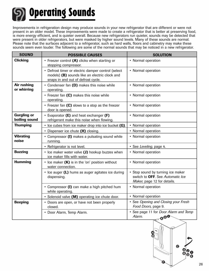
26
Operating SoundsImprovements in refrigeration design may produce sounds in your new refrigerator that are different or were notpresent in an older model. These improvements were made to create a refrigerator that is better at preserving food,is more energy efficient, and is quieter overall. Because new refrigerators run quieter, sounds may be detected thatwere present in older refrigerators, but were masked by higher sound levels. Many of these sounds are normal.Please note that the surfaces adjacent to a refrigerator, such as hard walls, floors and cabinetry may make thesesounds seem even louder. The following are some of the normal sounds that may be noticed in a new refrigerator.
SOUNDClicking
Air rushing or whirring
Gurgling or boiling soundThumping
Vibrating noise
Buzzing
Humming
Beeping
POSSIBLE CAUSES• Freezer control (A) clicks when starting or
stopping compressor.• Defrost timer or electric damper control (select
models) (B) sounds like an electric clock andsnaps in and out of defrost cycle.
• Condenser fan (D) makes this noise whileoperating.
• Freezer fan (C) makes this noise whileoperating.
• Freezer fan (C) slows to a stop as the freezerdoor is opened.
• Evaporator (E) and heat exchanger (F)refrigerant make this noise when flowing.
• Ice cubes from ice maker drop into ice bucket (G).• Dispenser ice chute (H) closing.• Compressor (I) makes a pulsating sound while
running.• Refrigerator is not level.• Ice maker water valve (J) hookup buzzes when
ice maker fills with water.• Ice maker (K) is in the ‘on’ position without
water connection.• Ice auger (L) hums as auger agitates ice during
dispensing.
• Compressor (I) can make a high pitched humwhile operating.
• Solenoid valve (M) operating ice chute door.• Doors are open, or have not been properly
closed.• Door Alarm, Temp Alarm.
SOLUTION• Normal operation
• Normal operation
• Normal operation
• Normal operation
• Normal operation
• Normal operation
• Normal operation• Normal operation• Normal operation
• See Leveling, page 4.• Normal operation
• Normal operation
• Stop sound by turning ice makerswitch to OFF. See Automatic IceMaker, page 12 for details.
• Normal operation
• Normal operation• See Opening and Closing your Fresh
Food Doors, page 9. • See page 11 for Door Alarm and Temp
Alarm.
I
E
K
H
F
J
G
M
A
DB
C
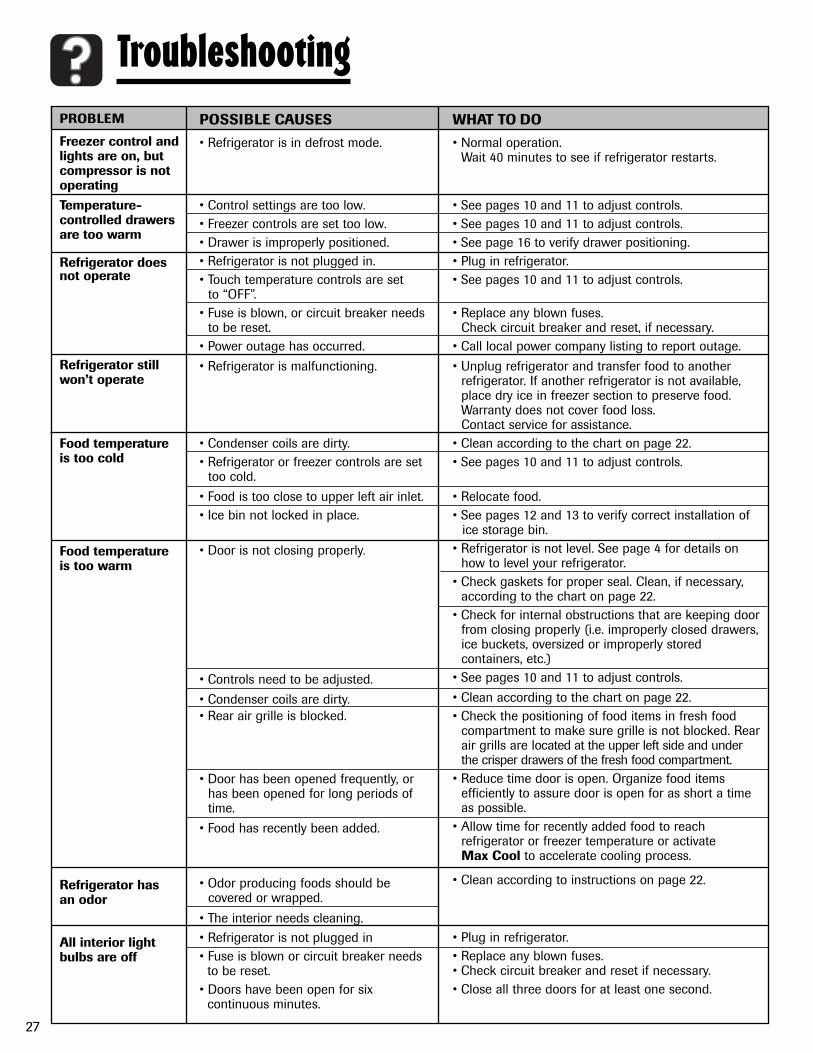
27
TroubleshootingPROBLEM
Freezer control and lights are on, but compressor is not operatingTemperature- controlled drawersare too warm
Refrigerator does not operate
Refrigerator still won’t operate
Food temperature is too cold
Food temperatureis too warm
Refrigerator has an odor
All interior lightbulbs are off
POSSIBLE CAUSES
• Refrigerator is in defrost mode.
• Control settings are too low.• Freezer controls are set too low.• Drawer is improperly positioned.• Refrigerator is not plugged in.• Touch temperature controls are set
to “OFF”.• Fuse is blown, or circuit breaker needs
to be reset.• Power outage has occurred.
• Refrigerator is malfunctioning.
• Condenser coils are dirty.• Refrigerator or freezer controls are set
too cold.
• Food is too close to upper left air inlet.• Ice bin not locked in place.
• Door is not closing properly.
• Controls need to be adjusted.
• Condenser coils are dirty.• Rear air grille is blocked.
• Door has been opened frequently, or has been opened for long periods of time.
• Food has recently been added.
• Odor producing foods should be covered or wrapped.
• The interior needs cleaning.• Refrigerator is not plugged in• Fuse is blown or circuit breaker needs
to be reset.• Doors have been open for six
continuous minutes.
WHAT TO DO
• Normal operation. Wait 40 minutes to see if refrigerator restarts.
• See pages 10 and 11 to adjust controls.• See pages 10 and 11 to adjust controls.• See page 16 to verify drawer positioning.• Plug in refrigerator.• See pages 10 and 11 to adjust controls.
• Replace any blown fuses. Check circuit breaker and reset, if necessary.
• Call local power company listing to report outage.
• Unplug refrigerator and transfer food to another refrigerator. If another refrigerator is not available, place dry ice in freezer section to preserve food. Warranty does not cover food loss. Contact service for assistance.
• Clean according to the chart on page 22.• See pages 10 and 11 to adjust controls.
• Relocate food.• See pages 12 and 13 to verify correct installation of
ice storage bin.• Refrigerator is not level. See page 4 for details on
how to level your refrigerator.• Check gaskets for proper seal. Clean, if necessary,
according to the chart on page 22.• Check for internal obstructions that are keeping door
from closing properly (i.e. improperly closed drawers,ice buckets, oversized or improperly stored containers, etc.)
• See pages 10 and 11 to adjust controls.
• Clean according to the chart on page 22.• Check the positioning of food items in fresh food
compartment to make sure grille is not blocked. Rearair grills are located at the upper left side and under the crisper drawers of the fresh food compartment.
• Reduce time door is open. Organize food items efficiently to assure door is open for as short a time as possible.
• Allow time for recently added food to reach refrigerator or freezer temperature or activate Max Cool to accelerate cooling process.
• Clean according to instructions on page 22.
• Plug in refrigerator.• Replace any blown fuses.• Check circuit breaker and reset if necessary.• Close all three doors for at least one second.

28
Troubleshooting
Water droplets formon inside ofrefrigerator
Refrigerator or ice maker makes unfamiliar sounds or seems too loud
Crisper drawersdo not close freely
Refrigerator runs too frequently
PROBLEM POSSIBLE CAUSES
• See pages 10 and 11 to adjust your controls.• Reduce time door is open. • Organize food items efficiently to assure door is
open for as short a time as possible.
• Clean, if necessary, according to the chart onpage 22.
• See page 26 for Operating Sounds.
• Reposition food items and containers to avoidinterference with the drawers.
• See pages 17-18 to verify drawer positioning.
• See page 4 for details on how to level yourrefrigerator.
• Clean drawer channels with warm, soapy water.• Rinse and dry thoroughly.• Apply a thin layer of petroleum jelly to drawer
channels.
• Reduce time door is open. • Organize food items efficiently to assure door is
open for as short a time as possible.
• Allow interior environment to adjust for period thedoor has been opened.
• Normal operation.
• Allow time for recently added food to reachrefrigerator or freezer temperature.
• Evaluate your refrigerator’s environment.Refrigerator may need to be moved to run moreefficiently.
• Clean according to the chart on page 22.
• See pages 10 and 11 to adjust your controls.
• Refrigerator is not level. See page 4 for details onhow to level your refrigerator.
• Check gaskets for proper seal.
• Clean, if necessary, according to the chart onpage 22.
• Check for internal obstructions that are keepingdoor from closing properly (i.e. improperly closeddrawers, storage bins, oversized or improperlystored containers, etc.)
• See Operating Sounds on page 26.
WHAT TO DO
• Humidity levels are high or door hasbeen been opened frequently.
• Check gaskets for proper seal.
• Normal operation.
• Contents of drawer or positioning ofitems in the surrounding compartmentcould be obstructing drawer.
• Drawer is not in proper position.
• Refrigerator is not level.
• Drawer channels are dirty or needtreatment.
• Doors have been opened frequently orfor long periods of time.
• Humidity or heat in surrounding areais high.
• Food has recently been added.
• Refrigerator is exposed to heat byenvironment or by appliances nearby.
• Condenser coils are dirty.
• Controls need to be adjusted.
• Door is not closing properly.
• Normal operation

29
Troubleshooting
Refrigerator isleaking water
Water flow is slower than normal
Ice storage binwill not close
Water filter indicator light is red
Ice forms in inlet tube to ice maker
Ice and WaterPROBLEM POSSIBLE CAUSES
• Plastic tubing was used to completewater connection.
• Improper water valve was installed.
• Water pressure is low.
• Improper water valve was installed.
• Copper tubing has kinks.
• Water filter is clogged or needs to bechanged.
• Ice cube blockage
• Water filter needs to be replaced.
• Filter indicator sensor needs to bereset.
• Water pressure is too low
• Saddle valve not open completely.
• Freezer temperature is too high.
• The manufacturer recommends using copper tubingfor installation. Plastic is less durable and can causeleakage. The manufacturer is not responsible forproperty damage due to improper installationor water connection.
• Check water connection procedure (see pages 8-9).Self-piercing and 3⁄16” saddle valves cause low waterpressure and may clog the line over time. Themanufacturer is not responsible for propertydamage due to improper installation or waterconnection.
• Water pressure must be between 35 to 100 poundsper square inch to function properly. A minimumpressure of 35 pounds per square inch isrecommended for refrigerators with water filters.
• Check water connection procedure in yourInstallation Instructions. Self-piercing and 3⁄16”saddle valves cause low water pressure and mayclog the line over time. The manufacturer is notresponsible for property damage due toimproper installation or water connection.Open water valve completely and check for leaks.
• Turn off water supply and remove kinks. If kinkscannot be removed, replace tubing.
• Change water filter (see page 14).
• Remove spilled ice cube(s) before replacing icestorage bin.
• If filter is not available, replace with bypass filter.See Water Filter, pages 14-15.
• See Filter Status Indicator Light, page 10.
• Water pressure must be between 35 to 100 poundsper square inch to function properly. A minimumpressure of 35 pounds per square inch isrecommended for refrigerators with water filters.
• Open saddle valve completely.
• See Temperature Controls, pages 10 and 11. Freezertemperature should be between 0° to 2° F (-18° to -17° C) to produce ice.
WHAT TO DO

30
Troubleshooting
Ice maker is not producing ice
Temp Alarm Lightis flashing
All lights on dispenser andinterior lights areoff and applianceis still running
Door alarm set, noalarm sounded
Temperatures indisplay look too low
PROBLEM POSSIBLE CAUSES
• Ice maker switch is not ON
• Household water supply is notreaching water valve.
• Copper tubing has kinks.
• Water pressure is too low.
• Check freezer temperature.
• Inner fountain door is blocked orfrozen.
• Exceeded normal operatingtemperatures.
• Control has been set to SabbathMode.
• Alarm mode has been disabled.
• Temperature display has been set toCelsius rather than Fahrenheit.
• Confirm ice maker switch is ON. See Automatic IceMaker, pages 12-13.
• See Connecting the Water Supply, pages 8-9.
• Turn off water supply and remove kinks. If kinkscannot be removed, replace tubing.
• Water pressure must be between 35 to 100 poundsper square inch to function properly. A minimumpressure of 35 pounds per square inch isrecommended for refigerators with water filters.
• See Temperature Controls, pages 10 and 11. Freezertemperature should be between 0° to 2° F (-18° to -17° C) to produce ice.
• Do not attempt to free the fountain door bycontinuously pressing the dispenser button. Contactqualified service technician.
• See Temp Alarm, page 11.
• See, Sabbath Mode, page 11.
• To activate audible alarms, refer to page 11.
• See Temperature display on page 10.
WHAT TO DO


