Service Handbook - Agilent · Agilent 1049A illustrated parts breakdown 57 ... The Main Power...
68
s1 Agilent 1049A Electrochemical Detector Service Handbook
Transcript of Service Handbook - Agilent · Agilent 1049A illustrated parts breakdown 57 ... The Main Power...

s1
Agilent 1049AElectrochemical Detector
Service Handbook

Agilent Technologies Deutschland GmbHHewlett-Packard-Strasse 876337 WaldbronnGermany
Copyright Agilent Technologies 2000
All rights reserved. Reproduction, adaption, or translation without prior written permission is prohibited, except as allowed under the copyright laws.
Part No. 01049-90101
Edition 10/00
Printed in Germany
Warranty
The information contained in this document is subject to change without notice.
Agilent Technologies
makes no warranty of
any kind with regard to
this material,
including, but not
limited to, the implied
warranties or
merchantability and
fitness for a particular
purpose.
Agilent Technologies shall not be liable for errors contained herein or for incidental or consequential damages in connection with the furnishing, performance, or use of this material.

Service Handbook
Agilent 1049A Electrochemical Detector

Using This Handbook
Installation, performance verification and test features of the Agilent 1049A
electrochemical detector are described in the Operator’s Handbook.This Service Handbook contains informations about the hardware, cables and connectors and a parts reference list.
4

Contents
1 Main Power Supply
Voltage Distribution 9
2 Keyboard and Display Module
General Description: 16
3 Electrochemical Detector Controller Board
General Description 20Processor & Control 24Data Processing 25D/A Conversion 26
4 Electrochemical Detector Preamplifier Board
General Description: 35Diagnose 36
5 Flow Temperature Controller Board
General Description 41
6 Connectors and Cables
Integrator and Auxiliary Output 44Remote 48
5

Contents
7 Parts Identification
Agilent 1049A illustrated parts breakdown 57Agilent 1049A Keyboard 60Agilent 1049A Rear Panel 62Agilent 1049A Flow Cell 64Agilent 1049A Miscellaneous Parts 66
6

1
1 Main Power Supply

Main Power Supply
MPS-board 01046-66501
Exchange Part Number: 01046-69501
The Main Power Supply works with a switching frequency of 50 kHz and is covered with sheet metal to prevent high frequency radiation and shock hazard.
The line voltage is routed through the line filter, line fuses and power switch to the Main Power Supply (MPS).
Values of the fuses are:
• 100-120V: 1 A slow (part number 2110-0007)
• 220-240V: 0.5 A slow (part number 2110-0202)
WARNING Hazardous voltage are present at the output connector with
instrument power cord connected to the AC line.
Figure 1 Warning Label and Power Select Switch
8

Main Power SupplyVoltage Distribution
Voltage Distribution
All boards with analog circuits have their own +15 V regulators. The GND line separates in the Main Power Supply and forms analog GND line (AGND) and a digital GND line (DGNG).
The following voltages can be measured on the Electrochemical Detector Controller Board:
Each voltage is fused. LED’s indicate the proper function of the fuses.
Figure 2 Main Power Supply Board
Voltage Variation
+ 5 V + 10%
+ 19 V + 10 %
+ 24 V + 10 %
- 19 V - 10 %
- 35 V - 15 %
9

Main Power SupplyVoltage Distribution
Figure 3 Agilent 1049A Voltage Distribution
10

Main Power SupplyVoltage Distribution
Main Power Supply Board (MPS)
The line voltage selector switch S1 inside the instrument selects either 220-240V or 100-120V.
The Main Power Supply contains the electronics of the switched power supply. The output voltage on the secodary side of the transformer depends on the duty cycle for the Power-FET (pulse-width modulation).
A main rectifier supplies the switching transformer, whereas a second auxiliary rectifier supplies the regulation circuit.
Regulation is implemented only for the +5 V DC line. Regulation of other DC voltages depends on power coupling by the transformer core. These DC voltages are regulated on the respective boards.
The error amplifier senses the +5 V DC line which has PID characteristics due to noise on the +5 Volts. The voltage on the sense line is compared with a reference voltage and an error signal is generated. This error signal is fed through an analog opto coupler into the error sense input of the power control circuit, where it is used to control the duty cycle of the pulse-width modulated signal. The pulse width is inversely proportional to the error signal, and has less than 45% duty cycle. To prevent the transformer working at saturation, and causing current spikes which may destroy components, no more than 45% duty cycle is used.
The power control cicuit limits the current through the switching transformer with the help of sense line. It senses the voltage drop and compares it with a reference voltage. As soon as an overcurrent condition is reached, the pulse-width signal at the output of the control circuit is reduced. This results in a limited current through the switching transformer.
The error amplifier senses an overvoltage condition on the +5 Volt line. Overvoltage turns-OFF the power control circuit. After a short delay, the power control circuit turns-ON again. If the over voltage condition, remains it turns-OFF again. The oscillating frequency is approximately 1 Hz which can be observed at the green LED.
The power control circuit senses an undervoltage condition on the auxiliary rectifier. The power control circuit turns-OFF, as long as its supply voltage is below +9 Volt. When sensing this undervoltage condition, the power control circuit generates the power fail signal (POF-) and feeds it through an opto coupler to the input latch on the detector controller board (ECC). If power fails, the controller stores all setpoints in the battery backed-up memory.
11

Main Power SupplyVoltage Distribution
12

2
2 Keyboard and Display
Module

Keyboard and Display
Module
KDM-assembly (01049-66508)
Exchange Part Number: 01049-69508
The keyboard and display module (KDM) is located behind the front panel of the instrument.
Figure 4 Front Panel of Agilent 1049A
14

Keyboard and Display Module
Figure 5 Agilent 1049A KDM Block Diagram
15

Keyboard and Display ModuleGeneral Description:
General Description:
Two grid drivers select the position of the character to be displayed, and drive the 32-character vacuum tube fluorescent display. The controller loads the characters sequentially from the data bus via buffer, using the load master (LDM) and load slave (LDS) lines. The pattern generator determines which character pattern will be displayed. It is loaded from the grid drivers.
The Electrochemical Controller Board (ECC) supplies the filament voltage (FIL) with a frequency of 22 kHz.
Latches drive the RUN LED, ERROR LED and NOT READY LED, whereas the POWER LED is connected to the -35V line.
Buffers drive the keyboard matrix through 6 lines (row drive). The controller reads the keyboard matrix through 8 lines (column read).
16

3
3 Electrochemical
Detector Controller
Board

Electrochemical Detector
Controller Board
ECC-board 01049-66501
Exchange Part Number: 01049-69501
The Electrochemical Detector Controller Board (ECC) is the heart of the Agilent 1049A. This one board contains the whole management of Potentiostat, D/A and A/D Conversion, Amplification, Input/Output Devices, Analog Outputs, GPIB and Options. Connected to the ECC Board are the Pre-Amplifier Board (ECP), Keyboard Display Module (KDM), and the Flow Temperature Controller (FTC). Common Agilent 1049A functions for the processor are:
• display handling
• keyboard polling
• remote control input and output
• leak sensing
• option interfacing
• time programming
• method storage
• cell control
18

Electrochemical Detector Controller Board
Figure 6 Agilent 1049A ECC Board
19

Electrochemical Detector Controller BoardGeneral Description
General Description
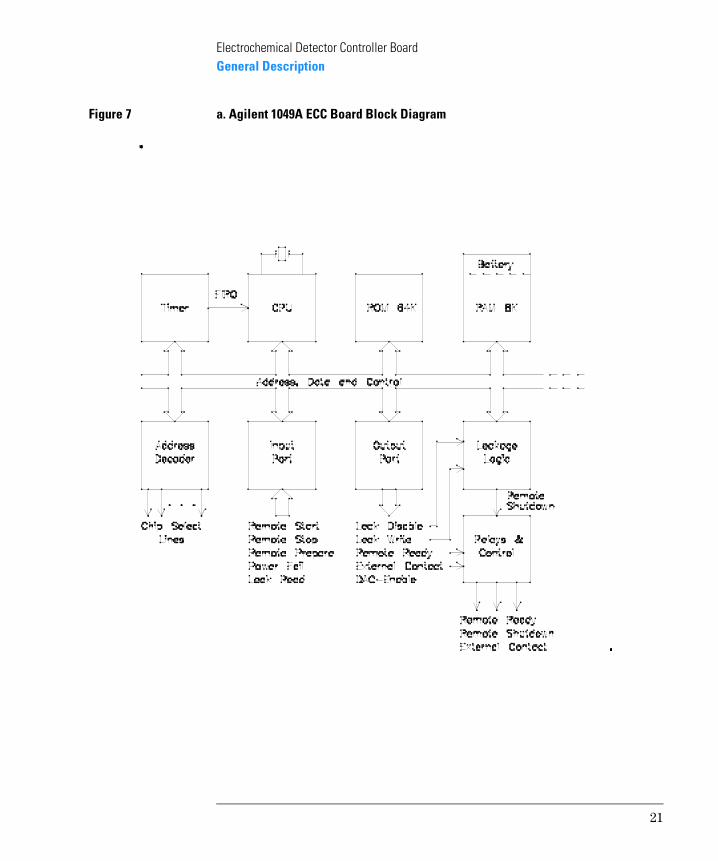
The heart of the controller hardware is a 6809 processor. The local bus system, which consists of a Control Bus, a 16 bit Address Bus and an 8 bit Data Bus, connects all functional groups on this board. The firmware is stored permanently in a 64 kbyte ROM. Data are stored temporarily in an 8 kbyte RAM which has an internal battery back-up to prevent loss of setpoints.
The power-ON logic supplies a reset to the processor when the power supply comes ON. It also gives a reset if undervoltage spikes occur on the 5 V power line. The programmable timer 68B40 delivers an input to the CPU with a frequency of 220 Hz.
20
Electrochemical Detector Controller BoardGeneral Description
Figure 7 a. Agilent 1049A ECC Board Block Diagram
21

Electrochemical Detector Controller BoardGeneral Description
Figure 8 b. Agilent 1049A ECC Board Block Diagram
22

Electrochemical Detector Controller BoardGeneral Description
Figure 9 c. Agilent 1049A ECC Board Block Diagram
23

Electrochemical Detector Controller BoardProcessor & Control
Processor & Control
The ECC board controls the signals going to and coming from the ECD cell. The potentiostat provides a voltage POTENTIAL to the auxiliary electrode and the reference electrode through a 16 bit D/A-Converter. This voltage works against a virtual ground. The solvent is now able to accept electrons (reduction-mode) or donates electrons (oxidation-mode), if it is ’electrochemical active’.
A current (signal) can be measured at the working electrode (WE). The signal can be compensated by a ZEROCURRENT. With the AutoZERO function this current can be choosen automatically. During a chromatogram the ZEROCURRENT remains stable.
On the Preamplifier Board (ECP), the current is converted to a voltage. With the INSTRUMENT FULLSCALE function, three gain factors can be selected. The converted voltage is fed to a Track&Hold circuit and a programmable gain amplifier on the ECC board for getting higher resolution with a standard 12 bit successive approximation converter. This value represents the signal current. The data processing section of the processor shows the value on the display, and guides it to the analog outputs.
24

Electrochemical Detector Controller BoardData Processing
Data Processing
Data is delivered to the Electrochemical Detector Controller Board (ECC). Data tasks include data bunching, boxcar filtering, and offset adjustment. The data bunching stage averages a certain number of datapoints. The boxcar filter takes a certain number of bunched data points (in this example 3) from the bunched signal and averages them to form the first boxcar filtered data point. The boxcar filter then leaves out the first bunched data point, adds the next bunched data point (n+1) and calculates a new average i.e. a new boxcar filtered data point. The length of the boxcar filter is called n. The resulting signal therefore contains the same number of data points as the originally bunched signal.
25

Electrochemical Detector Controller BoardD/A Conversion
D/A Conversion
The main functions of the Digital to Analog conversion are:
• conversion of digital data into analog signals compatible with external integrators;
• provide two independent analog signals
The D/A- logic comprises two independent pulse-width modulated 18 bit D/A converters.The repetition rate for the data per channel is 90Hz. The two analog outputs can be used for integrators and recorders.
Timers
Three 16 bit timers are available on the D/A section. One is fixed as a divider, and provides the 90 Hz clock for the control logic. The other two timers work as Pulse Width Modulators for channel 1 and 2. They are loaded with the digital word stored in the data storage area and activated with a 90 Hz clock. Starting with the loaded word, each counter will count downwards with the 6.555 MHz cycle.
Pulse Width Modulator
The pulses generated in the counter section are fed to diode switches that are responsible for switching ON or OFF the constant current source to the low pass filter section.
Output voltage -4 ...996mV (1V)
or -0.4 ...99.6mV
(100mV)
hardware switchable
Rise Time (10/90%): 0.1 sec
Noise : <4µV (at 0.1 sec rise time)
26

Electrochemical Detector Controller BoardD/A Conversion
Low Pass Filter
There are three low pass filters in series. All filters suppress the 90 Hz cycle. The cutoff frequency is <4 Hz and suppresses the 90 Hz with >100 dB. The third low pass filter has a variable gain, which allows a scale factor for the analog output voltage at 1V or 0.1V.
Power Supply
The +/- 19V from the Power Supply is used to generate +/- 15V and + 10V as a reference voltage for the constant current source.
Output Voltage Check
Check of outputvoltage is possible with an integrator or a voltmeter after a balance has been done. Following values are measurable (+/- 10%):
If these values can not be measured, the Analog-Output part may be defective. See chapter “Verifying the Performance of Your Detector” in the Operator's Manual.
Potentiostat
The potentiostat provides a fixed potential of the reference electrode (REF) referred to virtual ground of the amperometer. This is done by regulating the potentials in the +/- 14 V range applied to the auxiliary electrode (AUX) depending on changing signal currents or solvent impedances. Connected to the peripheral-data-bus, two 8 bit buffers create a 16 bit word. A 16 bit D/A-converter converts the word in an analog signal, and sends it to two active filters. The first filter converts the current to a voltage. The second filter is driven by the processor. The processor selects it either as a low-pass filter with a low frequency or as a low-pass filter with higher frequency. The low frequency is used in amperometric mode whereby the higher frequency in different pulse modes. The outputs of both filters are connected with the
Zero% Voltage [mV]
0 0
5 50
100 1000
27

Electrochemical Detector Controller BoardD/A Conversion
op-amp which makes up the potentiostat together with Auxiliary (AUX) and Reference (REF)- electrodes.
Zero Current
The zero current compensates the current coming from the Electrochemical Detector cell, so that the amperometer is working in the optimum range (around 0 nA).
The zero current is adjusted with a 12 bit D/A converter which has a microprocessor compatible interface. The converter is driven by the peripheral DATA bus. It uses its own reference voltage (+10V). An OP amp converts the output, which is then filtered with a low pass filter. Current compensation occurs on the Preamplifier Board (ECP).
Amperometer
On the ECP board, the signal coming from the detector cell is amplified and converted into a voltage. This voltage is measured.Relays define actual gain of the amperometer. With a programmable gain amplifier the voltage is supplied to the A/D converter with a resolution of 12 bit. The processor selects the amplification factor of the gain amplifier and gets by that a real resolution of 15 bit. Two 8 bit latches provide the digital signal to the processor. Digital filtering will perform then an analog output resolution of more than 18 bit.
Leak Detection
The leak detection circuit uses a PTC resistor as leak sensor. The sensor is part of the ECP-board. If there is a leak, the PTC is cooled by the fluid, and the resistance of the PTC decreases. Hence a cooled PTC results in an increased voltage at TPL1. As soon as the voltage exceeds the voltage applied by the resistor divider to the positive input of comparator, its output goes LOW at TPL3. If the PTC is disconnected or any connection to it is broken, a comparator provides a low going output signal at TPL3, since the voltage is lower than the voltage applied to the negative input of a comparator. Outputs are read via LKRD- line from the processor.
• LKRD- is LOW (TPL3), if the voltage on TPL1 is less than 80 mV (defective) or if the voltage on TPL1 is greater than 5.8 V (leak).
• LKRD- (TPL3) delivers pulses from LKWR-, if the voltage on TPL1 is in the range of 150 mV to 4.4 V.
28

Electrochemical Detector Controller BoardD/A Conversion
If LKRD- line is LOW (TPL3), the processor generates the Error Message: ERROR: leak detected. In addition, the LKRD-signal is used to switch a relay. The relay (contact closure in case of leak) can be used to turn-OFF external instruments (e.g. LC pumps). The relay acts independently of the controller. A NTC resistor is used for ambient temperature compensation.An automatic selfcheck is implemented in the leak detection circuit. The processor sends a LKWR- signal of 10 µs pulse width and a repetition rate of 0.6 seconds. This signal (TPL2) is fed into a circuit to simulate a leak for the duration of the pulse. The processor which reads the LKRD- line is able to decide if the leak detection circuit is functioning properly.
The 10 µs pulses have no effect on the relay as they are filtered out by a low pass filter. LKDIS- line inhibits the leak detection circuit for the first minute after power-ON to ensure proper operation.
Working condition of the PTC
Actions:
• Check for a leak.
• Check voltage at TPL1 and resistance of leak sensor.
• Change ECP board.
GPIB Interface
The Electrochemical Detector has a built-in GPIB Interface. It consists of a 32 kByte RUN buffer, circuits for IN/OUTput and GPIB control.
NOTE The Pascal Workstation doesn’t support the electrochemical detector.
GPIB Controller
The main part of the GPIB section is the GPIB controller which communicates with the processor through the data and address bus. In addition the GPIB controller uses the Interrupt path (IRQ). A 4 MHz clock triggers the GPIB controller. Two drivers send the data to the IN/OUTPUT port of the GPIB interface.
Normal: About 75°C/400 … 500 ΩError: Below 55°C/about 150 Ω
29

Electrochemical Detector Controller BoardD/A Conversion
Run Buffer Logic
A Run Buffer stores the data before they are sent to the GPIB interface. A latch creates a special bus system. This bus addresses the buffer. The 16 bit address is stored in two 8 bit buffers.
The buffer gets its address from two 8 bit buffers. The data transfer is done through the special data bus. The switch shows the GPIB address of the Electrochemical Detector. This information is also storable inside the buffer.
LEDs
If the green LED labeled IRQ- is ON, all interrupts have been served (if LED is OFF, CPU has a lock up); Five green LEDs indicate the voltages supplied to the controller. The LEDs are labelled +5 V, +/-19 V, +24 V and -35 V respectively. If a LED is ON, the corresponding voltage is supplied to the controller.
Remote Control
The processor drives the IN/OUTput ports and the External Contacts. The output port delivers the following signals:
• READY: for the ready relay (contact closure);
• LKWR-: leads to the input from leak detection circuit. A pulse of 10 µs duty cycle is delivered from the processor approximately every 0.6 seconds;
• LKDIS-: to disable the leak detection circuit for 1 minute after power-ON;
• DACEN: to enable the analog outputs AUXILIARY and INTEGRATOR.
• EXT CONTACT: an addition connector; activated (contact closure) for pen up/down or remote start of non Agilent-devices.
The input port senses:
• external contacts: START- and STOP- (TTL level);
• LKRD-: from output of the leak detection circuit. The response from leak detection circuit is read on this line. If LKRD- does not follow LKWR-, the leak detection circuit is defective;
• POF: to indicate a Power-OFF failure.
• PREPARE: external contacts: activates prepare controlled operations
Remote control allows easy connection between single instruments or systems to ensure coordinated analysis with simple coupling requirements.
30

Electrochemical Detector Controller BoardD/A Conversion
Connector
For the Agilent 1049A Electrochemical Detector the subminiature D connector is used. Two remote connectors are provided which are both parallel and both inputs and outputs.
To provide maximum safety within a distributed analysis system, one line is dedicated to SHUT DOWN the system’s critical parts in case a leak is detected.
Control of the analysis is maintained by signal readiness READY for the next analysis, followed by START of run and optional STOP of run triggered on the respective lines. In addition PREPARE may be issued.
The signal levels are defined as standard TTL levels (0V is logic true, + 5V is logic false).
To help you make the correct connections, the signals carried on each pin are listed below (the colors refer to wires of remote cable 01046-60201).
A full description is done in chapter ’Connectors and Cables’ in this manual.
Pin Signal Active Color
1 Digital ground white
2 Prepare run LOW brown
3 Start LOW gray
4 Shut down LOW blue
5 Reserved pink
6 not used
7 Ready HIGH red
8 Stop LOW green
9 not used
31

Electrochemical Detector Controller BoardD/A Conversion
Signal description
SHUT DOWN (L) The system has a serious problem (e.g. leak: stops pump). The receiver is any module capable of reducing the safety risk.
POWER ON (H) All modules connected to the system are switched on. The receiver is any module relying on the operation of others.
READY (H) The system is ready for the next analysis.The receiver is any sequence controller.
PREPARE (L) Request to prepare for analysis (e.g. zero balance, pretreatment).The receiver is any module performing preanalysis activities.
32

4
4 Electrochemical
Detector Preamplifier
Board

Electrochemical Detector
Preamplifier Board
ECP-board 01049-66502
Exchange Part Number: 01049-69502
The Preamplifier Board (ECP) is the interface between the Electrochemical Detector Cell and the Processor Board (ECC). Three electrodes are connected to the Preamplifier Board:
• working electrode (WE)
• reference electrode (REF)
• auxiliary electrode (AUX)
Figure 10 Agilent 1049A ECP Board
34

Electrochemical Detector Preamplifier BoardGeneral Description:
General Description:
Figure 11 Agilent 1049A Operating Schematic
The reference electrode is connected to the potentiostat through pin 9 (labelled blue), and to the auxiliary electrode through pin 5 (labelled red). Opening S2 isolates the auxiliary electrode from the potentiostat. In addition, relay S1 can connect the reference and auxiliary electrodes together. The cell current, which is the signal of the working electrode, is guided to an OP-amplifier (OPII). The OP-amp is connected to ’virtual ground’. Relay S3 disconnect the working electrode from the electronic for test purpose (dummy cell test).
With relays, three ranges are selectable (50 nA, 500 nA and 500 uA). The output signal of the preamplifier is guided through connector J21 to the amplifier of the data aquisition electronics on the Electrochemical Detector Controller Board (ECC). Compensation of the measurent current is done with the zero current which is delivered from the ECC board through connector J21.
The local bus system, consisting of a Control Bus, a 16-bit Address Bus and an 8-bit Data Bus, connects all functional groups on this board. All relays are driven from the processor.
35

Electrochemical Detector Preamplifier BoardDiagnose
Diagnose
For diagnostic purposes a 1 MΩ shunt resistor can be connected instead of the detector cell. This is done with the dummy cell test mode from the instrument keyboard (MODE = TEST1; dummy cell test). This enables a complete electronic test to be done.
Reference electrode
Figure 12 Schematic of the Reference Electrode Test
To diagnose the reference electrode, the REF-connection is grounded and the equilibrating potential of the redox-preaction (Ag/AgCl) is measured by means of the auxiliary electrode.
Working electrode
To diagnose the working electrode, a cyclovoltamogram with the background current of the solvent should be done. Now, compare this with a cyclovoltamogram done with a ’good’ working electrode.
36

Electrochemical Detector Preamplifier BoardDiagnose
Leak sensor
Figure 13 Location of the leak sensor
The leak sensor is soldered to the ECP board. During operation the leak sensor should be placed inside the leak tray.
CA UTIO N In case of a leak, dry the leak sensor with a tissue. Do not blow on the leak sensor or use a fan to dry the leak sensor.
37

Electrochemical Detector Preamplifier BoardDiagnose
38

5
5 Flow Temperature
Controller Board

Flow Temperature
Controller Board
FTC-board 01049-66503
Exchange Part Number: 01049-69503
Figure 14 Agilent 1049A FTC Board
Heat exchanger: 01049-66901
Exchange Part Number: 01049-69901
Figure 15 Agilent 1049A Heat Exchanger
The Flow Temperature Controller Board (FTC) and the Heat Exchanger are optionally installed in the 1049A. The board includes a temperature control circuity with a 8 bit D/A-converter which makes the temperature setting controllable by the processor. The board is connected to the Electrochemical Detector Controller Boeard (ECC). Hardware interfacing at this place is universally defined for future option handling.
J1
40

Flow Temperature Controller BoardGeneral Description
General Description
Figure 16 Schematic of Flow and Temperature control
The flow temperature controller as an option is realized by sensing the temperature of the heat exchanger with a Platinium resistor (PT 100). The heat exchanger is installed nearby the inlet steel capillaries of the detector. It is isolated in an aluminium/PU-foam sandwich for better energy transfer and low ambient temperature interference. The capillaries are bent around a heating element which is fed by a special power line (+24V).
The controller compares the voltage across the Platinium resistor with the voltage which is get by the 8 bit D/A-converter according to temperature range of 20 to 60°C. The differential signal is now transferred to a pulse width modulator with a PI-behaviour. The modulator limits power losses in the power regulation circuit. Feedback is done thermally in the heat exchanger element.
For controlling present states of the circuit there are three window comparators for checking whether regulation is above or under the required setting or even out of specified temperature range. Out of range will cause an ERROR (shutdown), over/under temperature will cause a NOT READY on the remote bus and status will be seen.
Depending on the flow rate of the chromatographic system, the time for definite temperature setting will be different from seconds to some minutes.
41

Flow Temperature Controller BoardGeneral Description
42

6
6 Connectors and Cables

Connectors and Cables
Integrator and Auxiliary Output
Figure 17 Agilent1049A Rear Panell
The Integrator and the Auxiliary Output connectors provide either a 100 mV or a 1 V maximum signal output at the BNC-connectors. The full-scale voltage range of both outputs is presetted at the factory at 0 to 1 V. Changing the full-scale voltage range can be done by a switch on the ECC-board individually for each output.
Available analog cables for the Agilent 1049A Electrochemical Detector are listed below and on the following pages.
44

Connectors and CablesIntegrator and Auxiliary Output
Agilent 1049A to HP 3390/2/3 Integrators
or Signal Distribution Module 01090-60300
Agilent 1049A to HP 3394 and Agilent 3396 Integrators or Agilent
35900 Interface
Connector(Part Number 01040-60101)
Pin3390/2/3
Pin1049A Signal Name
1 Shield Ground
2 Not connected
3 Center Signal +
4 Connected to pin 6
5 Shield Analog -
6 Connected to pin 4
7 KEY
8 Not connected
Connector(Part Number 35900-60750)
Pin3394/6
Pin1049A Signal Name
1 Not connected
2 Shield Analog -
3 Center Signal +
45

Connectors and CablesIntegrator and Auxiliary Output
Agilent 1049A to HP 18562 Interface
Agilent 1049A to HP 1084 LC
Connector(Part Number 01046-60103)
Pin18562
Pin1049A Signal Name
3 Shield Analog -
4 Centr Signal +
F KEY
Connector(Part Number 8120-1840)
Pin1084
Pin1049A Signal Name
Shield Shield Analog -
Center Center Signal +
3
46

Connectors and CablesIntegrator and Auxiliary Output
Agilent 1049A to General Purpose
Connector(Part Number 01046-60105)
WireColor
Pin1049A Signal Name
BLACK Shield Analog -
RED Center Signal +
47

Connectors and CablesRemote
Remote
Both remote connectors are identical and connected in parallel.
The Prepare Run, Start and Stop are low active TTL level inputs.
The prepare run signal can be used to get some features of the Agilent 1049A Electrochemical Detector e.q. Pretreatment for cleaning the working electrode before run.
If the detector is not ready it generates a contact closure not ready signal. If a leak is detected, a shut-down signal is activated, which can be used to stop a solvent pump.
The table below lists signals which are used by the Agilent 1049A Electrochemical Detector.
NC = Not Connected
Table 1 Pin assignment 1049A
Pin# Signal Action
1 Digital Ground
2 Prepare Run Low active input
3 Start Low active input
4 Shut down Contact closure output
5 NC
6 NC
7 Ready Contact closure output
8 Stop Low active input
9 NC
48

Connectors and CablesRemote
Agilent 1049A to HP 3390 Integrator
NC = Not Connected
Agilent 1049A to HP 3392/3 Integrator
Connector(Part Number 01046-60203)
Pin3390
Pin1049A Signal Name (Active)
2 WHT 1 Digital Ground
NC BRN 2 Prepare Run (LOW)
7 GRA 3 Start (LOW)
NC BLU 4 Shut Down (LOW)
NC PNK 5 Not Connected
NC YEL 6 Not Connected
NC RED 7 Ready (HIGH)
NC GRN 8 Stop (LOW)
NC BLK 9 Not Connected
Connector(Part Number 01046-60206)
Pin3392/3
Pin1049A Signal Name (Active)
3 WHT 1 Digital Ground
NC BRN 2 Prepare Run (LOW)
11 GRA 3 Start (LOW)
NC BLU 4 Shut Down (LOW)
NC PNK 5 Not Connected
NC YEL 6 Not Connected
9 RED 7 Ready (HIGH)
1 GRN 8 Stop (LOW)
NC BLK 9 Not Connected
4 - KEY
49

Connectors and CablesRemote
Agilent 1049A to HP 3394 Integrator
Connector(Part Number 01046-60210)
Pin3394
Pin1049A Signal Name (Active)
9 WHT 1 Digital Ground
NC BRN 2 Prepare Run (LOW)
3 GRA 3 Start * (LOW)
NC BLU 4 Shut Down (LOW)
NC PNK 5 Not Connected
NC YEL 6 Not Connected
5, 14 RED 7 Ready (HIGH)
3 GRN 8 Stop ** (LOW)
1 BLK 9 Not Connected
13, 15 Not Connected
* = START and STOP are connected via diodes to pin 3 of the HP 3394 connector.** = START and STOP are connected via diodes to pin 3 of the HP 3394 connector.
50

Connectors and CablesRemote
Agilent 1049A to Agilent 3396 Integrator
Agilent 1049A to HP 1050 or Agilent 35900 A/D converter
Connector(Part Number 03394-60600)
Pin3396
Pin1049A Signal Name (Active)
9 WHT 1 Digital Ground
NC BRN 2 Prepare Run (LOW)
3 GRA 3 Start (LOW)
NC BLU 4 Shut Down (LOW)
NC PNK 5 Not Connected
NC YEL 6 Not Connected
5, 14 RED 7 Ready (HIGH)
6 GRN 8 Stop (LOW)
1 BLK 9 Not Connected
13, 15 Not Connected (LOW)
Connector(Part Number 5061-3378)
Pin1050
Pin1049A Signal Name (Active)
1 WHT 1 Digital Ground
2 BRN 2 Prepare Run (LOW)
3 GRA 3 Start (LOW)
4 BLU 4 Shut Down (LOW)
5 PNK 5 Not Connected
6 YEL 6 Not Connected
7 RED 7 Ready (HIGH)
8 GRN 8 Stop (LOW)
9 BLK 9 Not Connected (LOW)
51

Connectors and CablesRemote
Agilent 1049A to HP 18562 Interface
Agilent 1049A to HP 1090 LC or Signal Distribution Module
Connector(Part Number 01046-60204)
Pin18562
Pin1049A Signal Name (Active)
B WHT 1 Digital Ground
NC BRN 2 Prepare Run (LOW)
C GRA 3 Start (LOW)
NC BLU 4 Shut Down (LOW)
NC PNK 5 Not Connected
NC YEL 6 Not Connected
NC RED 7 Ready (HIGH)
NC GRN 8 Stop (LOW)
NC BLK 9 Not Connected
Connector(Part Number 01046-60202)
Pin1090
Pin1049A Signal Name (Active)
1 WHT 1 Digital Ground
NC BRN 2 Prepare Run (LOW)
4 GRA 3 Start (LOW)
7 BLU 4 Shut Down (LOW)
8 PNK 5 Not Connected
NC YEL 6 Not Connected
3 RED 7 Ready (HIGH)
6 GRN 8 Stop (LOW)
NC BLK 9 Not Connected
5 - KEY
52

Connectors and CablesRemote
Agilent 1049A to HP 1081B LC
Agilent 1049A to HP 1084 LC or Universal
Connector(Part Number 01046-60200)
Pin1081
Pin1049A Signal Name (Active)
E WHT 1 Digital Ground
NC BRN 2 Prepare Run (LOW)
B GRA 3 Start (LOW)
D BLU 4 Shut Down (LOW)
C PNK 5 Not Connected
NC YEL 6 Not Connected
NC RED 7 Ready (HIGH)
NC GRN 8 Stop (LOW)
NC BLK 9 Not Connected
Connector(Part Number 01046-60201)
PinUniversal
Pin1049A Signal Name (Active)
WHT 1 Digital Ground
BRN 2 Prepare Run (LOW)
GRA 3 Start (LOW)
BLU 4 Shut Down (LOW)
PNK 5 Not Connected
YEL 6 Not Connected
RED 7 Ready (HIGH)
GRN 8 Stop (LOW)
BLK 9 Not Connected (LOW)
53

Connectors and CablesRemote
54

7
7 Parts Identification

Parts Identification
This chapter gives diagrams for parts identification and the complete parts listings respectively.
• Overall Diagram
• Keyboard
• Rear Panel
• Flow Cell
• Miscellaneous Parts
56

Parts IdentificationAgilent 1049A illustrated parts breakdown
Agilent 1049A illustrated parts breakdown
Figure 18 Exploded View
57

Parts IdentificationAgilent 1049A illustrated parts breakdown
Table 2 Agilent 1049A Exploded View
# Description Part number
1 Cover top 5021-3663
2 Cover bottom 5021-3662
3 Rear panel assembly 01049-60015
4 Keyboard assembly no part number
5 Cover side 5061-8320
6 Side panel 01049-00202
7 Screw 0515-0750
8 ECD inlet 01049-27601
9 ECD outlet 01049-27602
10 Washer 2190-0596
11 Nut hex 0535-0116
12 Leak drawer 01049-44502
13 Foot 4040-2098
14 Screw 0515-1118
15 ECP-board 01049-66502
16 Cable assy 5061-3359
17 MPS-board 01046-66501
18 Cover MPS-board 01046-04101
19 Screw 0515-0886
20 ECC-board 01049-66501
21 Screw 0515-1507
22 ECD cabinet 01049-04401
23 Assy sheet 01049-06501
24 ECD cell 01049-68700
24a Mounting clamp 5021-1866
58

Parts IdentificationAgilent 1049A illustrated parts breakdown
25 Waste tube 01049-27301
26 Tube flex 0890-1711
27 Nut 0100-0771
28 Gasket 01049-07101
29 Connector tube 01049-27302
30 Leaktray 01049-44501
31 FTC-board (opt.) 01049-66503
32 Screw 0515-0886
33 Heat exchanger (opt.) 01049-66901
34 Insulation 4324-0159
Table 2 Agilent 1049A Exploded View, continued
# Description Part number
59

Parts IdentificationAgilent 1049A Keyboard
Agilent 1049A Keyboard
Figure 19 Keyboard Exploded View
60

Parts IdentificationAgilent 1049A Keyboard
Table 3 Keyboard
# Description Part number
1 Frontpanel 01049-40201
2 Keyboard 01049-66508
3 Holder upper 01046-02301
4 RFI strip 8160-0392
5 Holder lower 01046-02302
6 Screw 0515-0886
7 Frontpanel cover 01049-04101
8 Screw 0515-0886
61

Parts IdentificationAgilent 1049A Rear Panel
Agilent 1049A Rear Panel
Figure 20 Rear Panel
62

Parts IdentificationAgilent 1049A Rear Panel
Table 4 Rear Panel
# Description Part number
1 Cable interface 5061-3352
2 Panel GPIB 01090-00215
3 GPIB scewIncluded in item 1
4 BDG post 1510-0038
5 Wash lock 2190-0084
6 BDG post 1510-0038
7 O-ring 0905-1185
8 Nut hex 0535-0006
9 Cable clamp 1400-0024
10 Screw 2200-0105
11 Cable assy 01046-61604
12 Screw lock 1252-1518
13 Screw 0515-0886
14 Switch rocker 3101-2913
15 Screw M3.5 0515-0887
16 Fuse holder 2110-0610
16a Fuse holder cap 2110-0565
16b Nut hex plastic 2110-0569
63

Parts IdentificationAgilent 1049A Flow Cell
Agilent 1049A Flow Cell
Figure 21 Agilent 1049A Electrochemical Detector Cell
64

Parts IdentificationAgilent 1049A Flow Cell
Table 5 Agilent 1049A Flow Cell
# Description Part number
1 Working electrode disc glassy carbon 01049-64105
1a Working electrode disc platinum (opt.) 01049-28801
1b Working electrode disc gold (opt.) 01049-28802
2 Working electrode assembly 01049-60013
2a Silicon tubing 5062-2474
3 Electrode swifel nut 01049-25701
4 Reference electrode solid state 01049-62901
4a Reference electrode intern. electrolyte (opt.)Seal reference electrodeused for 4 and 4a
01049-62902
01049-47102
5 Cell body black (auxiliary electrode) 01049-27708
6 Electrode socket no part number
7 FEP spacer 01049-24705
8 Auxiliary electrode connection 01049-27604
9 Inlet tubing PTFE, red 01049-27305
9a Silicon tubing 5041-8355
10 Ferrule 20/Pk 5061-3321
10a Gripper 20/Pk 5061-3322
10b Male 20/pk 5061-3323
10c Buffer disc 20/Pk 5061-3324
11 Inlet connection nut and ferrule 5021-1867
12 Outlet tubing PTFE, blue 01049-27306
65

Parts IdentificationAgilent 1049A Miscellaneous Parts
Agilent 1049A Miscellaneous Parts
Table 6 Agilent 1049A Miscellanous Parts
# Description Part number
1 ECD inlet capillary 01048-87302
2 ECD outlet capillary 01040-67602
3 Plug external contact 1251-4782
4 Connector external contact 1251-3911
5 Fuse 1 A 2110-0001
6 Fuse 2 A 2110-0002
7 Fuse 0.5 A 2110-0012
8 Fuse 0.1 A 2110-0236
9 Pipe insulation 1 m 5021-7131
10 Polishing kit 01049-67001
10a Diamond paste no part number
10b Polishing disc 5955-3794
11 KCL electrolyte solution 01049-92101
66


s1In This Book
Installation, performance verification and test features of the Agilent 1049A electrochemical detector are described in the Operator’s Handbook.
This Service Handbook contains informations about the hardware, cables and connectors and a parts reference list.