InnovatIve SolutIonS experIence & technology - insage.com.my

Serviceexperience
Two-stroke technologies

MAN Energy SolutionsService experience – two-stroke technologies
Futurein the
making
2
ME-GI service experience 5Service experience with fuel gas supply systems 10Cylinder condition of G95ME-C-9.5 15TCEV and FBIV introduction 28G95 TCEV service experience 33G95 FBIV service experience 38Common rail system description 41Common rail service experience 44Tier III technologies 49Conclusion 51
Contents
3
tests on a 6S50ME-C8.1 engine have been completed successfully. In July 2018, the first MAN B&W two-stroke engine of the type 6S35ME-CR9.5 entered service after extensive tests at the Makita test bed in Takamatsu, Japan. We will describe the lessons learned until now. At the time of writing, the CR (common rail) technology in service in general works very well.
The Tier III technologies, exhaust gas recirculation (EGR) and selective catalytic reduction (SCR), are introduced on a large numbers on vessels currently being commissioned. However, service hours from vessels operating in Tier III mode are still limited because of the few operating hours in ECA zones. However, we have introduced a Tier II version of the EGR system, EcoEGR. EcoEGR is used in Tier II mode outside of Tier III zones with a recirculation rate of the order 10-15%. We will present the latest service experience from this system, which is logging considerably more service hours than other Tier III systems.
A large number of ME-GI engines have entered service successfully. These engines are installed in various types of vessels like container carriers, car carriers and bulk carriers. However, the majority of the ME-GI engines have un-til now been installed in vessels that carry fuel as cargo. These ship types are LNG carriers (ME-GI), ethane carri-ers (ME-GIE) and methanol carriers (ME-LGIM).
We have introduced various upgrades based on service experience from the first ME-GI engines. These upgrades include software upgrades aimed at increasing surveillance of the control valves as well as software and upgrades aimed at lowering the specific pilot oil consumption (SPOC) and reducing pressure peaks in the hydraulic cylinder unit (HCU) blocks when injecting pilot fuel.
The gas atomiser development will be touched upon along with other mechanical upgrades related to the gas components.
Challenges with the ME-GI fuel gas supply system will be described and
the improvements will be discussed in detail.
In the beginning of 2016, a number of large container vessels for global trade were fitted with MAN B&W 11G95ME-C9.5 engines. The service experience gained from these engines soon revealed a number of aspects concerning the engine design that had to be addressed, amongst others issuing new operational guidelines and understanding engine operation conditions on these types of large container ships.
The top-controlled exhaust valve (TCEV) and fuel booster injection valve (FBIV) technology has been service tested extensively during the past years, and the first commercial engine orders with this technology have been successfully shop tested. We will describe the development from the service tests on the first versions of the S50 engines to the latest results of service tests on the G95 engines.
Common rail injection technology has also been introduced in the engine programme. Comprehensive service
This paper describes in detail the service experience of ME-GI, ME-GIE and ME LGIM engines. Furthermore, the latest experience from our large bore engines is described. Technologies to meet Tier III requirements, and our new TCEV/FBIV designs are also touched upon.
MAN Energy SolutionsService experience – two-stroke technologies4

On our first methane fuelled engine we are well above 13,000 gas running hours whereas our first ethane fuelled engine reaches 10,000 hours on gas in just 20 months – a record which will be hard to beat for any dual-fuel two-stroke engine. In 2017, we experienced a few cases of overheating of the gas-block on the ME-GI engines after gas purging. On one of the vessels, engine operation continued on liquid fuel while the crew tried to restart gas operation without trouble shooting. An electronic gas injection (ELGI) valve stuck in open position resulted in overheating of the gas-block and damage to various seals. In order to avoid this, we introduced the new engine control system (ECS) software with supervision of the ELGI position feedback. This made it impossible to restart gas operation before the ELGI valve was exchanged or rectified, see Fig. 1. Since this modification was introduced (at the time of writing it is one and a half year ago) no further incidents have occurred.
and owners has led to the introduction of our GI Mk. 2 design.
The positive results from our ME-GI engines in service have also brought reduction of the pilot oil consumption into focus. The introduction of newly designed injection profiles for pilot oil has provided a significantly better performance as well as a reduction of the specific pilot oil consumption (SPOC). Currently, we have vessels in service with a SPOC well below 3%, and we are getting closer to our new 0.5% target.
Since our first steps into the two-stroke dual-fuel market, we have introduced new technologies in an impressive way over the years. In October 2015, the first commercial vessel operating on methane (LNG) was introduced and in April 2016, the first vessel using methanol entered service. March 2017, the first vessel using ethane entered service and in October 2018, we presented the first ever two-stroke engine using liquified petroleum gas (LPG).
Fig. 1: Position feedback supervision of the ELGI valve
Since the introduction to the market in 2015, the ME-GI engine has taken the position as the market leader and thus already proven the concept of dual fuel propulsion. With more than 60 dual fuel engines in service, our two-stroke engine programme covers methane, ethane and methanol.
As first mover on the market, we have faced a number of challenges. The rapidly increasing number of running hours on our dual fuel engines has enabled us to analyse and follow up on design improvements and feedback to maintain the position as the most reliable dual fuel engine on the market.
The high number of accumulated running hours does not only prove the concepts, it has also given us valuable feedback. The feedback is already used and will be used for improvements and optimisation of the design in the future.
Several modifications have already been implemented and introduced, since the initial design was released. The feedback from engine operators
ME-GI service experience
3.15 A ELGI valveControl signalCylinder n
ELGI Valve OKFeedbackCylinder n
ELGI positionFeedbackCylinder n
ELGI valve cyl n
ELGI
MPC
ELWIvalve
Gasaccumulator
Gas inj.valves
Gas pressure
Window valve
Valve closed
To GI injection valves
To silencer
Seal oil
Gas block
Purgevalve
Blow offvalve
ELGIvalve
5

6
Fig. 3: Left: New 0.7 L accumulator, right: Old 0.2 L accumulator
Fig. 2: Individual adjustment of the pilot oil amount for each cylinder
The same ECS software made it possible to perform individual (from cylinder to cylinder) adjustment of the pilot oil amount. In this way, the crew could reduce the amount of pilot oil
significantly from the main operating panel (MOP), see Fig. 2.
On the hydraulic side, the use of an enlarged gas-block accumulator (Fig. 3)
has solved issues with damage to the accumulator diaphragms. Furthermore, the time between nitrogen re-charges has been increased to an acceptable level.
MAN Energy SolutionsService experience – two-stroke technologies

A redesign of the control oil pipe from the HCU to the gas-block, by using a combination of hydraulic hose and pipe, has solved issues with broken control oil pipes, see Fig. 4.
The new pilot oil profile shown in Fig. 5 has lowered the hydraulic peaks in the HCU block. After this change the solenoid valves for the cylinder oil lubricators stopped failing. Furthermore, the new profiles have improved air venting of the cylinder prior to injection. It is also possible to lower the SPOC further with the new profiles. Initial results show an improved condition of the fuel injection valves (FIVs), however, more operating hours are needed to confirm this.
Fig. 4: Control oil pipe design with a combination of hose and pipe
Fig. 5: Modification of the pilot oil profile
-30 10 20 30 40 50
-2
-1
0
1
2
3Orginal ProfileOptimised profile
7
MAN Energy SolutionsService experience – two-stroke technologies8
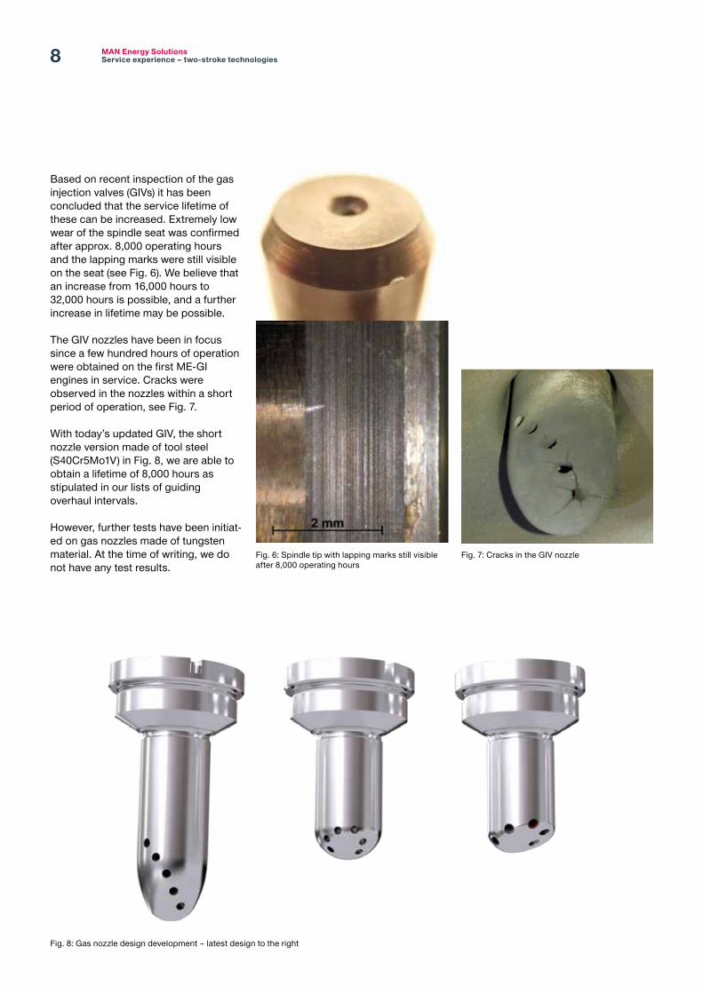
Based on recent inspection of the gas injection valves (GIVs) it has been concluded that the service lifetime of these can be increased. Extremely low wear of the spindle seat was confirmed after approx. 8,000 operating hours and the lapping marks were still visible on the seat (see Fig. 6). We believe that an increase from 16,000 hours to 32,000 hours is possible, and a further increase in lifetime may be possible.
The GIV nozzles have been in focus since a few hundred hours of operation were obtained on the first ME-GI engines in service. Cracks were observed in the nozzles within a short period of operation, see Fig. 7.
With today’s updated GIV, the short nozzle version made of tool steel (S40Cr5Mo1V) in Fig. 8, we are able to obtain a lifetime of 8,000 hours as stipulated in our lists of guiding overhaul intervals.
However, further tests have been initiat-ed on gas nozzles made of tungsten material. At the time of writing, we do not have any test results.
Fig. 7: Cracks in the GIV nozzleFig. 6: Spindle tip with lapping marks still visible after 8,000 operating hours
Fig. 8: Gas nozzle design development – latest design to the right

9
too-high additivation of calcium. We gave the instructions to operate about 24 hours on high-BN oil and 48 hours on low-BN oil. The intervals can be altered (extended) based on inspections. Clean ring lands and ring grooves can be maintained in this way, see Fig. 11, and a good cylinder condition is generally experienced on the ME-GI engines.
A manual for systematic analysis of gas trips, i.e. gas alarms and shutdowns, has been made available to the crew on board the ME-GI driven vessels. This manual contains an analysis of the gas pressure curve (Fig. 9) and it provides a description of various deviations from the normal curve caused by known failures. The manual enables the crew to perform more qualified troubleshooting on board to rectify issues on a unit quickly in case of a gas trip.
We have gained experience with the cylinder condition when the engine operates continuously on gas. The continuous operation on low-sulphur fuel has given us some ideas about the challenges we will encounter after 2020, when the global sulphur cap comes into force. We have experienced that low base number (low BN) cylinder oils, which should be optimal for continuous low-sulphur fuel operation, did not have sufficient detergency for such operation. A build-up of deposits was seen on ring lands and ring grooves as shown in Fig. 10.To address this we issued a circular letter instructing operators of ME-GI engines to alternate between high-BN (100) cylinder oil for cleaning and low-BN (25-40) for counteracting the
Gas pressure
WV openTemperature =>
Sensor reset
Angle [degrees]BDCTDC TDC135 180 225 270 315 360 45 90 135 180 225
Pressure increase
WV close
Gas injection stopGas injection start
Gas injectionWindow valve
Fig. 9: Gas pressure curve analysis
Fig. 10: The continuous operation on low-sulphur fuel and the use of low-BN cylinder oils give insufficient detergency
Fig. 11: The continuous operation on low-sulphur fuel and the alternating use of high- and low-BN cylinder oil give sufficient detergency

MAN Energy SolutionsService experience – two-stroke technologies10
supply pressure for the main engine and to 300 bar for the cargo re-liquefaction system. Additionally, the compressor supplies gas at 8 bar to the auxiliary engines, see the common FGSS in Fig. 12.
FGSS for LNG carriers
Large LNG carriers are commonly delivered with large boil-off gas (BOG) compressors that compresses BOG from the cargo tanks to the 300 bar
The dual fuel engines depend on reliable fuel gas supply systems (FGSS) in order to operate on secondary fuels. Our service experience will be described in the following sections.
Fig. 12: FGSS for LNG carriers
Service experience with fuel gas supply systems
LNG cargo tanks
2×5G70ME-C9.2-GI
300 bar, 45˚C
300 bar
6 bar, 60˚C
BCA Laby – GI compressor
DF GenSets (3×7L35/44DF, 1×6L35/44DF)
LNG vaporiser
LNG heater
LNG supply pump
Suction drumLNG HP pump
LNG HP pump
Flash drum
GCU
Cold box

11
Boil-off gas compressors
Figs. 13 and 14 show two sizes of commonly used compressors. We have experienced a number of issues with these compressors that have been rectified. Wear of the high-pressure piston rod packing in stage 4/5 has been observed and the solution is replacement of the high-pressure packing, see Fig. 15 and the labyrinth piston rod glands. Fig. 14: 5LP250-5B_1 modelFig. 13: 6LP190-5C_1 model
Fig. 15: Modified high-pressure packing

MAN Energy SolutionsService experience – two-stroke technologies12
Gas valve train The gas valve train (GVT) with the latest inlet filter, slow-opening valve and spool pieces for easy gas pipe flushing is seen on Figs. 17 and 18.
The above-mentioned problems have resulted in compressor downtime and in higher operating costs for the owners. Furthermore, a long delivery time for spare parts has aggravated these cases. MAN Energy Solutions (MAN ES) has pressed the maker of the compressors very hard to clarify these important issues. Furthermore, we work hard at introducing alternative compressor suppliers.
Furthermore, oil transfer from the compressor to the LNG tanks has been seen. The solution is installation of an oil trap system before the BOG returns to the LNG tanks, see Fig. 16.
For the 190-type compressor, the piston rod design has been modified with a new piston rod with an increased diameter.
Fig. 16: Oil trap system before the LNG tanks
Fig. 17: GVT with inlet filter and slow-opening valve
Fig. 18: Spool pieces in GVT piping
PRS
Separator
Coalescing Filter 1
Coalescing Filter 2
«Adsorbtion» Filter Cold Box
Joule-Thomson Valves
Knock-out Drum
Vent ValveBypass Valve
From Compressor Stage 5
To HP Vent Mast
To ME-GI
Auto Drain Auto Drain
Manual Drain
Manual Drain
NRV Block Valve Block Valve
Block Valve
Liquefied Methane
Condensate Return
LNG Cargo Tanks
Cryogenic Filter
Vent Valve
To Gas Dome
Block Valve
(1) (2)
(3) (4)*
(5.1)
(5.2)
(6)
Major design modifications & improvements implemented:
(1) Cyclone separator design improvement (improved efficiency)(2) Coalescing filter design improvement and re-location (to main delivery)(3) 2nd coalescing filter design improvement(4) Possibility to install optional/additional adsorbtion filter (vapor removal)(5) Additional vent valve in line to PRS – avoid reverse flow(6) Additional cryogenic filter in condensate return line (removal of solid oil
particles, vapor content)
Major achievements:
- Efficient oil removal- No oil “spillage” caused by (a) rapid de-compression and
(b) reverse flow- Significant efficiency improvement of filtration equipment- Cryogenic filter to remove oil vapor before entering the
knock-out drum (yard scope)
Future outlook:
- Adsorbtion filter technology to remove vapor content before entering the PRS (in trial phase)
- “ideal” lubricant – special PAG oil with lowest possible vapor content
Flash Gas

13
Increased wear occurred on the gas valve seats due to an excessive amount of particles in the gas piping after installation (Fig. 19), caused by the fact that gas supplied from bunker barges and trucks is not as clean as expected and that the valves in the GVT are sensitive to dirt. Because of this, larger 10 micron fine filters were introduced on the gas side before the GVT, see Fig. 20.
High-pressure pumps
In some cases the LNG high-pressure (HP) pumps have had a limited service time because the cold end of the pumps has been worn. The wear has been caused by contamination of gas and piping and the solution is an installation of a cryogenic 10 micron filter in front of the HP pumps, see Fig. 21.
Fig. 19: Dirt particles in LNG
Fig. 21: The cryogenic 10 micron filter should be installed before the HP pumpsFig. 20: 10 micron fine filter before the GVT
MAN Energy SolutionsService experience – two-stroke technologies14
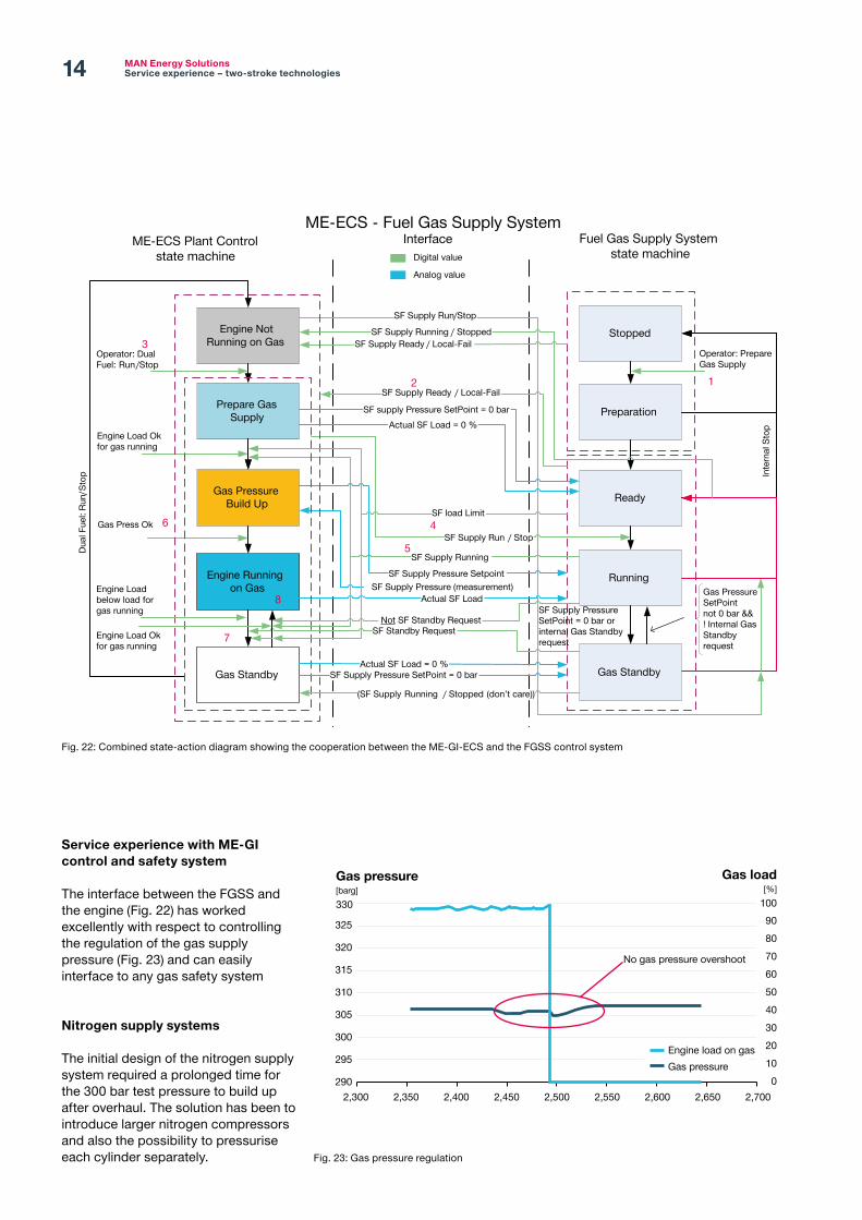
Service experience with ME-GI control and safety system
The interface between the FGSS and the engine (Fig. 22) has worked excellently with respect to controlling the regulation of the gas supply pressure (Fig. 23) and can easily interface to any gas safety system
Nitrogen supply systems
The initial design of the nitrogen supply system required a prolonged time for the 300 bar test pressure to build up after overhaul. The solution has been to introduce larger nitrogen compressors and also the possibility to pressurise each cylinder separately.
Fig. 22: Combined state-action diagram showing the cooperation between the ME-GI-ECS and the FGSS control system
Fig. 23: Gas pressure regulation
Stopped
Preparation
Ready
Fuel Gas Supply System state machine
InterfaceME-ECS - Fuel Gas Supply System
Inte
rnal
Sto
p
Engine Not Running on Gas
Prepare Gas Supply
Engine Load Ok for gas running
ME-ECS Plant Controlstate machine
Gas Press Ok
Engine Running on Gas
Operator: Dual Fuel: Run /Stop
SF Supply Ready / Local-Fail
SF Supply Run / Stop
Actual SF Load
SF Supply Run/Stop
SF Supply Ready / Local-Fail
Digital value
Analog value
Running
Gas Pressure Build Up
SF Supply Running
SF Supply Pressure SetpointSF Supply Pressure (measurement)
Dual
Fue
l: Ru
n/St
op
12
3
4
5
6
Gas Standby Gas StandbyActual SF Load = 0 %
SF Supply Pressure SetPoint = 0 bar
SF Standby Request
Engine Load below load for gas running
Not SF Standby RequestEngine Load Ok for gas running
SF supply Pressure SetPoint = 0 barActual SF Load = 0 %
Gas Pressure SetPoint not 0 bar &&! Internal Gas Standby request
SF Supply Pressure SetPoint = 0 bar or internal Gas Standby request7
8
Operator: Prepare Gas Supply
SF load Limit
(SF Supply Running / Stopped (don’t care))
SF Supply Running / Stopped
Gas pressure[barg]330
Gas load[%]
100
325
Engine load on gasGas pressure
320
315
310
305
300
295 1020304050
70
90
60
80
02902,350 2,400 2,450 2,500 2,550 2,600 2,650
No gas pressure overshoot
2,7002,300

15
is related to situations where the engine experiences load changes. It has led to a new functionality in the load programme (controlled in the ECS software) that protects the engine during load changes. The detailed background and the new functionality will be presented.
Design challenges
As mentioned above, the service experience indicated the need for improving the scuffing resistance.
Our design efforts in this respect have been focused on the following main points:
– piston ring design – piston ring quality – liner design – engine control system
Piston ring design
The first focus was the piston ring design, and this lead to a number of changes, see Fig. 24.
chamber was lower than seen on other similar engine types.
The level of corrosive wear and the impact on the cylinder condition will be discussed in detail. This includes the tests and countermeasures, which led to optimisation of the lube oil strategy and temporary operational guidelines. To improve the cylinder condition, a number of focus areas were identified and service tests were initiated to improve running conditions and longevity of liners and piston rings. Some of the tests in the test programme had a more significant impact on improving the issues than others. The tests, which have shown significant results, will be presented. Among others, the design history of the piston rings will be discussed with respect to the cause and countermeasures of each step in the G95 piston ring development.
Based on the comprehensive collection of data, new insights have been gained into piston ring running behaviour with regard to scuffing. The new knowledge
In the beginning of 2016, a number of large container vessels for global trade were fitted with MAN B&W 11G95ME-C9.5 engines. The service experience soon revealed a number of aspects concerning the engine design that had to be addressed, amongst others issuing new operational guidelines and understanding engine operation on these types of large container ships.
Consequently, a number of tests were initiated in cooperation between the owners and MAN ES in order to improve the cylinder condition, where the main challenge was the short time between overhaul due to scuffing. A key part of the evaluation of the initiated tests was the collection and processing of operational data. Such data is today accessible in the CoCoS Engine Diagnostic System, which records ECS data. Besides, operational data was collected from the alarm monitoring system. Once the engine was in operation, it was observed that the degree of cold corrosion inside the combustion
Cylinder condition of G95ME-C9.5
Fig. 24: Piston ring evolution

MAN Energy SolutionsService experience – two-stroke technologies16
The different ring versions led to version L2, today’s standard for G95 engines. Version L2 is characterised by an asymmetric barrel shape of the top ring, and a lower second and third ring with symmetric barrel shape. All three rings have a cermet hard coating (CM1) with a running-in layer (alucoat) on top (Fig. 25).
This ring pack has a good service record without scuffing incidents, see Fig. 26.
Fig. 26: Accumulated cylinder units in service without any scuffing cases
Fig. 25: L2 piston ring configuration
– Asymmetric barrel shape
– CM1 hard coating thick
– Thin alucoat as run in
– CM1 hard coating thin
– Thick alucoat as run in
– Symmetric barrel shape
– Lower rings
80
90
100
Units accumulated in service
70
60
50
40
30
20
10
0Sep.2017
Oct.2017
Nov.2017
Dec.2017
Jan.2018
Feb.2018
Mar.2018
Apr.2018
May.2018
Jun.2018
Jul.2018
Aug.2018
Sep.2018
Oct.2018
Nov.2018
Dec.2019
Jan2019
Feb.2019

17
The ring-pack version H5 has a similarly good record with no scuffing, see Fig. 27.
Piston ring quality
In the early days, the majority of scuffing occurred in the period just after the alucoat had been worn off. This led us to focus on the roughness of the CM1 layer, which is specified as “as-sprayed.” Pictures, where the CM1 layer has penetrated the alucoat, (Fig. 28) showed many small dots indicating a too high surface roughness.
This phenomenon is known to cause scuffing. In addition, some defects were discovered in the coating matrix with un-molten particles, which may potentially weaken the coating matrix.
In co-operation with the ring maker, the spraying parameters were optimised to reduce the surface roughness of the as-sprayed surface to improve the matrix of CM1.
Ring pack versions H5 and L2 are produced according to the new spraying parameters, and, as mentioned earlier, the service experience is very good.
Liner design
Four main design changes were introduced on the cylinder liners for the G95 engines. In the first inspections of the cylinder liner surface hard contact marks were found as indicated in Fig. 29.
Firstly, reducing the inner diameter of the PC-ring solved the upper contact problem and increased the clearance between the O-ring and the cylinder frame at the lower contact point, which resulted in an increased PC-ring efficiency. Secondly, a longer liner cooling jacket was introduced to improve both the liner deformation and the cooling of the piston rings, see Fig. 30 (left side). As a third countermeasure the airflow path below the liner was
– Asymmetric barrel shape
– CM1 hard coat thick
– Thin alucoat as run in
– CM1 hard coat thin
– Thick alucoat as run in
– Symmetric barrel shape
Fig. 27: H5 piston ring configuration
Fig. 28: Piston ring running surface where the hard coating (CM1) has penetrated the running-in alucoat
Fig. 29: Cylinder liner deformation and potential contact positions

MAN Energy SolutionsService experience – two-stroke technologies18
improved to reduce the air speed between the scavenge box bottom and liner as shown in Fig. 30 (right side).
The fourth countermeasure was an update of the rating-dependent cooling design (RDL) of the liner. The RDL concept ensures that engines with different ratings have more or less the same liner temperature. The lower cool-ing intensity needed for the lower-rated engines has been achieved by reducing the number of cooling bores and adapt-ing the positions of the individual cooling bores. Reducing the number of cooling bores results in a more unevenly distributed circumferential cooling which causes larger liner waviness, called bore distortion.
For the G95 engines the increased bore distortion led to a local increase in contact surface pressure as seen in Fig. 31.
Furthermore, the excessive bore distortion causes additional problems, especially during running-in of the liner and rings at shop test and sea trial.
The scuffing observed on the test bed during the shop test is considered closely related to the low-rated RDL liners. The bore distortion of these liners is significantly larger than the oil film thickness, as depicted in Fig. 32. If it gets too large, the piston rings cannot properly adapt to the liner anymore, causing a gas leakage past the rings’ running surface.
The original liner design, only used for the first 12 engines of the type 11G95ME-C9.5, had 30 cooling bores and did not have one single scuffing in-cident during sea trial. This led to a de-sign update of the RDL liners. The new updated liners for the G95 engines have an increased number of cooling bores and they are designed with the same level of bore distortion (or lower) as experienced on the first 11G95ME-C9.5 engines mentioned earlier.
Today, scuffing during sea trial is considered the result of a combination of too rapid load-up and too large bore
Fig. 30: Left: cylinder liner cooling jacket height; Right: clearance between liner and scavenge bottom
Fig. 31: Cylinder liner contact marks caused by bore distortion
Fig. 32: Illustration of exaggerated bore distortion and piston ring interaction
20 µmOil film 1 µm
Piston ring
distortion. The scuffing problems encountered with the old, low-rating RDL liners were solved completely with the introduction of a new software feature called an index rate limiter (IRL)
that protects the engine against rapid load-up. Since bore distortion is worn away in service and the IRL takes care of the running-in, the old RDL design is fully acceptable for operation.
625
Height increased 35 mm(i.e. shorter liner)

19
– Group recess system (GRS) machining. Ongoing
– Laser hardening, semi-honed. Ongoing
– Laser hardening, fully honed. Ongoing
– Pitch-honed liners. Ongoing
Lubrication testing – 1/8 high lubrication, Electronic Soft Delivery. Abandoned
– 1/8 high lubrication, standard timing. Ongoing
– 1/8 lubrication, SHHI (Single Hole Horizontal Insection). Ongoing
– Mk. 1 Alpha Lubricator. Ongoing – Controlled corrosion with BN70 outside ECA. Ongoing
– BN100 inside SECA. Abandoned – BN20-25, 24 hrs before entering SECA. Abandoned
– BN20-25, 12 hrs before entering SECA. Ongoing
– ACOM BN mixing. Ongoing – Increased minimum feed rate (0.8 g/kWh). Ongoing
– Increased load change dependent (LCD) active time. Ongoing
– LCD2 using HRN as controlling element (see later). Ongoing
Cooling water settings – Load dependent cylinder liner (LDCL) cooling stopped in all areas. Ongoing
– LDCL cooling stopped in SECA. Ongoing
– LDCL cooling flat low temperature. Ongoing
– LDCL cooling automatically adapting to high- or low-sulphur fuel. Ongoing/new standard
Engine Control System – Fine tuning “Torque mode” governor control. Ongoing/new standard
– “Load programme” extended. Ongoing/temporary changes
– Heavy running number used for LCDv2 control and reduction of P-rise etc., when running heavy. MAN Standard
– Index rate limiter. Ongoing/new standard
and most of the test results and components have remained in the engine for long-term analysis. Some features have been introduced without testing because they have been considered certain upgrades against scuffing. These upgrades are:
– The full cermet-coated ring pack as in version H3
– A change from two to three controlled leakage (CL) grooves in the top ring (version H4)
– The improved quality of the cermet and alucoating
– The asymmetric barrel shape of the top ring (H4)
– Return of the thick running-in alucoating for rings 2 and 3 (H5)
– Smaller inner diameter of PC ring
Below is a list of all the tests we have initiated to improve the scuffing resistance of the G95 engine. As mentioned, some tests have led to the definition of a new design standard, some have been abandoned, some have been implemented as a temporary remedy and some remain in service even though the results are not clear.
Piston ring testing – One high, two low rings, all cermet-coated. Now new engine standard
– One high, two low rings, the top ring is cermet-coated. Ongoing
– Three low rings, all cermet-coated. Ongoing
– Ground cermet-coated, all rings 3H. Ongoing
– Small radius barrel top ring. Ongoing – Small radius barrel ring, second and third rings have thick alucoat. Ongoing
– Extra pressure relief (additional CL grooves). Ongoing
– Alternative ring maker, no chromium. Ongoing
– All rings with CL grooves. Ongoing
Cylinder liner testing – Deformation compensated machining (DCM). Ongoing
– Long cooling jacket. Ongoing/new standard
– Shortened liner. Ongoing/new standard
Engine control system
Two new software features have been introduced to increase the margin against scuffing.
A significant number of scuffing incidents took place on sea trial in engines equipped with liners with significant bore distortion. These incidents could be related to quick load changes caused by, for example, rudder movement during manoeuvring. Subsequently this knowledge led to the first software feature, the introduction of the IRL, which for example protects the engine during sharp turns on sea trial.
Secondly, in situations with very distinct heavy running, the heavy running performance limiter (HRPL) reduces the maximum pressure, based on a heavy running number (HRN) calculated in the ECS. The collected service experience shows a significantly increased scuffing frequency in conditions with shallow waters, rough sea, and frequent engine start and stop. Consequently, a protection feature was developed based on the amount of heavy running, see later in this paper. Both features were introduced with a software update in 2018 (ECS1609).
Service test overview
During the first test bed running of the 11G95 engines, problems with iron embedment in the running-in coating were noticed and testing was initiated to improve the condition. The test bed performance was improved by introducing barrel-shaped second and third piston rings, and a thinner but stronger running-in coating ensured an intact barrel shape for a longer time.
Since the first scuffing incidents occurred during the first entrance of the North European SECA area, tests of various piston rings, liners, cylinder oil types, lubrication settings, cooling water settings and ECS parameters have been ongoing. A large part of the successful service test results have been implemented as a new standard

MAN Energy SolutionsService experience – two-stroke technologies20
the conventional temperature alerts implemented in most alarm systems as the alarm values continuously need to be readjusted and fluctuations not caused by scuffing can lead to frequent false alarms.
For this reason we have developed a scuffing identification algorithm, which has been used for the research & development (R&D) data analysis. Currently it is being tested on incoming data from a vessel with on-board diagnostics (OBD) installed.
Scuffing incidents at sea trial
As mentioned before, a detailed analysis of the data available from multiple sea trials with scuffing incidents revealed a connection between rapid load changes and scuffing incidents. So far, the present load-up restrictions for our engines were acting mainly on the speed set
Fig. 33: Liner wall temperature during scuffing
track of all relevant components installed on the engines with regard to scuffing with the aim to investigate the effect of all major design changes on the scuffing proneness of the engines.
Identification of scuffing
Maybe the most important task prior to any analysis is to locate scuffing in the available data. Best suited for this approach are the liner wall temperatures and liner jacket cooling water temperatures, which show the clearest response to scuffing. A scuffing incident, where two units simultaneously start scuffing, is shown in Fig. 33.
When scuffing occurs, the liner wall temperatures show fast frequent fluctuations in temperature and, in most cases, an increase of the overall temperature level. In general, these patterns are complicated to detect with
Performance tuning – Pmax reduced with 20 bar. Used when scuffing is suspected
Testing has been important in the reduction of the scuffing frequency, and the service experience for the latest G95 with all upgrades is satisfactory with regard to scuffing. However, we have not yet minimised the scuffing issue on all vessels in service to the level aimed at by MAN ES. Furthermore, we consider the general scuffing risk to increase with the increased number of SECA areas worldwide, where very-low-sulphur and ultra-low-sulphur fuels (VLSF and ULSF) have to be used, and with the general use of very-low-sulphur fuel (VLSF) after 2020 for vessels not fitted with a SOX scrubber.
The coming new engine types feature higher Pmax at reduced SFOC, and we therefore foresee that testing of components, ECS settings and lubrication features will remain important in our continuous development of the most scuffing-resistant engine.
Data analysis – big data
From the very beginning of the scuffing problems on the G95 engines, the data analysis of the massive amount of data from the various data sources available today from vessel and engine was under intensified focus. In the detailed analysis of the single scuffing incidents, data from the ECS, the alarm system, automatic identification system (AIS) data and other sources were combined to get a detailed insight into the factors that may cause scuffing incidents. However, it is still very complicated to prove the root cause as the definitive start of a scuffing incident is hard to identify. Liner and cooling water temperatures react with varying delays to the real start of local scuffing, and other sensors, for example the online drain oil sensors, have a rather low sample time.
Furthermore, a detailed study with a statistical approach was made to keep

21
Fig. 35 displays the locations of all scuffing incidents in 2018 for which the start of the incident could be clearly identified. About 70% of all scuffing incidents happened inside an Emission Controlled Area (ECA). Furthermore, scuffing has not only occurred in the European ECAs, but also in the Asian and American ECAs.
A decisive factor regarding scuffing is the engine load. It has been proven that scuffing is more likely to occur if the
In the following examples, only data from 2018 is used. This limitation is made because recent data represents the current engine design far best, e.g. all rings now have cermet coating. Furthermore, this limitation simplifies the data since scuffing on older designs showed a different pattern. Lastly, the number of scuffing incidents for which we could retrieve both the engine and alarm system data is much higher now than it was in the very beginning.
point of the engine. Yet, during sea trial, we encountered frequent increases in load, for example from 70 to 100% within seconds as shown in Fig. 34.
These sea trial phenomena were investigated by our engineers, and the first impression was that the vessel’s rudder movement had a significant influence on the engine load. This is especially relevant for the G95 engines mainly used in ultra large container vessels, since these feature an increased rudder size compared to older smaller vessels.
Based on the initial observations, a sea trial was performed where the key parameters related to scuffing were measured:
– engine load and speed – liner wall temperature – online measuring of the magnetic iron content in the drain oil.
The result clearly showed a connection between rapid load changes and a rise in iron content for the affected units.
Today, the IRL feature has been introduced on all large-bore engines and it successfully protects the engine against the externally introduced load changes.
Location of scuffing incidents for engines in service
At the time of writing, there are 522 G95 cylinders in service, which have now collected about 5.2 million running hours. We needed to keep detailed track of all scuffing incidents as well as of all the components installed on these engine, which are relevant to the cylinder condition in order to assess the impact of our design changes. Today, this database includes about 2500 piston rings, which have been or still are in service and which can be used for a detailed comparison of e.g. different piston ring pack types. However, the full details of this study do not fit within the scope of this paper. Instead, a more general insight into scuffing incidents on today’s large container vessels is given.
Fig. 34: Load changes during sea trial
Fig. 35: Location of scuffing incidents in 2018
Load [%] / Speed [rpm]100
95
90
85
80
75
70
05:53 05:57 06:00 06:04 06:08 06:11 06:15 06:19 06:22 06:26
LoadrpmECS speed setpoint
Engine performance without IRL
Time

MAN Energy SolutionsService experience – two-stroke technologies22
The HRPL feature reduces the pressure rise during heavy running of the engine. For an average vessel, this feature is only active for 2-3% of the engine’s running time, but precisely in challenging load conditions like fast load increases.
Fig. 38 depicts the pressure rise in the load diagram for an engine with HRPL. It is clearly visible how the pressure is reduced by up to 20 bar when approaching the allowed power limits of the engine.
and departures. In particular heavy running because of bad weather, shallow water and acceleration have demonstrated an increase of the thermal and mechanical load on the engine.
To protect the engine and to counteract these effects, a new software feature called a heavy running performance limiter (HRPL) was developed, which reduces the pressure rise in the engine during distinct heavy running operation.
engine speed is above 80% MCR speed, but there is no strong indication that scuffing happens solely at high engine load or speed as shown in Fig. 36.
A large fraction of all scuffing cases typically starts shortly after departure from a harbour, where load-up of the main engine takes place. More precisely, 55% of all scuffing cases occurred within the first 12 hours after departure. Besides the scuffing incidents occurring shortly after departure, there is another group of scuffing incidents, which take place after a fuel changeover from high- to low-sulphur fuel. In 2018, 25% of all scuffing cases took place within just 12 hours after such a fuel changeover, as shown in Fig. 37.
Finally, it is very interesting to note that there is no overlap between the two groups, and as a result, 80% of all scuffing cases in 2018 occurred within 12 hours after a change either of fuel or in load.
Heavy running performance limiter
The majority of scuffing cases in ECA operation and after load-up might partly be due to the increased amount of heavy running-in these areas and partly to the frequent harbour arrivals Fig. 36: Scuffing events 2018, grouped according to engine speed
Fig. 37: Scuffing incidents in 2018, grouped according to the cause of the incident
10-50 51-65 66-70 71-80 81-900
10
20
30
40
50
◼ 2018◼ All
Number of scuffings%60
91-100[% of MCR]Speed
Scuffing groups
Other
After fuel change
Afterdeparture
Fig. 38: Pressure rise shown in the load diagram
50 10 15 20 25 30 35 40
0
10
20
30
40
50
60
70
80
90
100
110
Load[%]120
0 10 20 30 40 50 60 70 80 90 100 110 [%]rpm

23
which consists of a stepwise reduction of the cylinder oil feed rate, one step every 24 hours while also taking drain oil samples. Once analysed, a graph can be drawn that shows the correlation between feed rate factor, the iron content and the BN of the drain oil. Fig. 39 shows the sweep test results that when using a BN100 cylinder oil a very low FRF is needed to control the cold corrosion.
One of the typical reasons for liner scuffing is liner bore polish, which may occur when using a too high feed rate and an oil with too high BN.
To optimise the G95ME-C9.5 operation, the operators were recommended to switch to BN70 oil instead of BN100 to ensure that the risk of bore polish was reduced, as many incidents had happened during manoeuvring. A temporary increase of the minimum feed rate from 0.6 to 0.8 g/kWh was also recommended. Once the new LCDv2 features were introduced with the new ECS 1609-6, the guiding minimum was again reduced to the normal 0.6 g/kWh. When using BN70, the FRF often remained low. Cold corrosive wear could only be observed when shutting down the LDCL cooling system and refraining from increasing the part-load temperature. However, liner
oil sulphur content, to ensure that enough BN is added to the cylinder liner surface to counteract the amount of sulphuric acid formed during the combustion. The best way to obtain the correct FRF is by monitoring the cylinder lubrication by analysing the waste oil drained from the bottom of the cylinder frame. The analysis of the “drain oil” has to be done regularly to monitor the engine condition, and it can also be used to determine if liner scuffing has occurred since the iron (Fe) content will rise from normally 100 to 200 mg/kg to above 1,000 mg/kg. Once in service, the drain oil analysis showed that the corrosive level of the G95 was less than that of similar S90ME-C10.2 engines.
The G95ME-C9.5 engine features all the countermeasures against cold corrosion:
– Load dependent cylinder liner cooling water system that increases the liner cooling water temperature at part-load up to 120ºC
– Rating dependent liner, which by design ensures that the cooling levels are the same for high and low rated engines
– The use of BN100 cylinder oil
The normal way to determine the correct FRF is to perform a stress test, also called a feed rate sweep test,
Additional lubrication during load changes
As for the load programme, our previous load change dependent (LCD) lubrication algorithm is not activated during engine load changes due to external influences, such as bad weather, manoeuvring, rudder operation, etc.
Additional lubrication is desired under these conditions to ensure refreshment of oil and flushing of wear particles. This is more relevant in case of scuffing initiation as it might prevent the change to a propagation phase where an abrasive contact dominates. Furthermore, the analysis of the online magnetic iron measurements shows that extra iron is created during load changes. Therefore, a reduction of the liner wear is also expected. The effect depends on the vessel operation.
The activation of the new LCDv2 is controlled by changes in the heavy running number (HRN), which is in contrast with the present activation by the speed set point change. We also took the opportunity to base the extra lubrication amount on the magnitude of the HRN change (instead of a fixed factor increase), making it suitable for each case.
Drain oil analysis and cylinder oil selection
One key aspect to the operators of modern two-stroke engines is to control the cold corrosion occurring inside the combustion chamber. On today’s engines the combustion pressure is high enough to cause condensation of water, combined with sulphur vapour from the combustion and an early expansion, water and sulphuric acid on the liner wall may cause heavy wear, if not controlled.
To control the impact of cold corrosion, a high-based cylinder oil is dosed in controlled amounts by the lubrication system. The feed rate of the cylinder oil is controlled by the feed rate factor (FRF), which is multiplied with the fuel
0
5
10
15
20
25
30
35
BN[mgKOH/g]
40
0
100
200
300
400
500
600
Fe [mg/kg]700
0.15 0.20 0.25 0.30 0.35 0.40
FeBN reserve
0.45[g/kWh x S%]
Feed Rate Factor
Engine Type: 11G95ME-C9.5Engine Load: 59%New Oil BN: 100Fuel Sulphur: 3.24%
Fig. 39: Feed rate sweep test

MAN Energy SolutionsService experience – two-stroke technologies24
connection with hard-coated piston rings, where a significant increase in the hardness of the piston ring surface has been introduced without changing the liner surface hardness. This is illustrated in the graphs in Figs. 41 and 42, where the min. and max. values of the Brinell hardness (Hb) are listed in historical order for both piston ring (Fig. 41) and cylinder liner (Fig. 42). The piston ring material Uballoy and liner material Tarkalloy constitute the original specifications used for the MC engine.
Service experience from operation on both low-sulphur and high-sulphur fuels have shown a very open graphite structure. Test on the G95 engines performed after the initial running-in have shown a clear improvement in the graphite openness when comparing the laser hardened liner with the reference liner, see Fig. 40.
In addition, the aim is to achieve a better hardness ratio between liner material and coating material. Such an improvement may be needed in
seizures still occurred, indicating that other factors have greater influence than bore polish.
The moderate level of cold corrosion indicates an opportunity to ensure a low consumption of lubrication oil in the future by utilising the LDCL cooling system with BN70 or BN100 cylinder oil.
New design features
In addition to the mentioned new features for G95, a number of tests provides some indication of the future cylinder liner piston ring configuration. One of these tests comprises a cylinder liner with an increased hardness of the liner surface.
Laser hardening of the cylinder liner surface is being tested on an 11G95ME-C9.5 engine. The aim of this design is twofold. Firstly, it is introduced to avoid bore polish by keeping an open graphite structure of the liner surface in connection with low sulphur operation, for example when running on ULSF in ECAs or running on gas in general. Secondly, it is introduced as a running-in feature for engines running on heavy fuel oil (HFO). The reason for this is that the laser hardening is only 0.5 mm deep.
Fig. 40: Enlarged photos of the liner surfaces, the standard liner surface on the right and the laser-hardened on the left
Fig. 42: Cylinder liner material hardness
Fig. 41: Piston ring material hardness
Uballoy CF5 CV1 CM1 CM20
100
200
300
400
500
600
700
800
900
1,000
◼ Hb min◼ Hb max
Tarkalloy Tarkalloy-C Tarkalloy-A Tarkalloy-Claser hardend
0
100
200
300
400
500
600
700
800
900
1,000
◼ Hb min◼ Hb max

25
Based on these figures, hard coatings CM1 and CM2 are good candidates in connection with increased hardness of the cylinder liner surface. The next step will be to test the concept on the test bed and on half of the cylinders on an engine in service.
Onboard diagnostics
For the first series of 11G95ME-C9.5 engines, it was decided to establish a digital connection between onboard and ashore, where key data from the ECS and the alarm system are transmitted in near real time together with important manually measured data such as wear measurements, etc. The OBD development started in 2012, and a status was presented at CIMAC in Helsinki in 2016. The name on-board diagnostics refers to the basic idea of making it easier for the chief engineer on board the ship to operate the engine in accordance with the instruction book. Benefits also exist for the shipowner, who will be able to follow the running condition of the engine in near real time with a web-based service. Normally, data are uploaded to the cloud every two hours, but upload as often as every minute can be chosen.
Until now, focus has been on retrieving data from the vessels and on generating automatic reports visible for
Iron (Fe)[mg/kg]500
0
100
200
300
400
0 10 20 30 40 50 60 70[mg KOH/g]
TBN
Onboard Ship XXX Engine 6G60ME-C9.2-TIISampled 5 January 2018 Lubricator MAN Alpha with ACC
1
234
56
Fig. 43: OBD drain oil analysis results
Fig. 44: OBD sweep test result
12345678910
0.21 0.24 0.27 0.30 0.33 0.36 0.39 0.42 0.45 0.48 0.51 0.54Feed Rate Factor [g/kWh x %S]
0
100
200
300
400
500
600
700
800
900
0
5
10
15
20
25
30
35
40
45
Iron[mg/kg] (avg: )
1,000
TBN[mg KOH/kg] (avg: )
50
all parties. One example is the drain oil analysis report that shows data in the same format as recommended in the prevailing service letter, see Fig. 43.
In the future, the OBD interface will be developed further, and various notifications will appear. As a starting point, the focus of these notifications will be on the cylinder condition and engine performance. The collected data is used by MAN ES to troubleshoot on a specific engine if an abnormal condition exists and, of course, also for R&D purposes.
Drain oil analyses play an important role for the cylinder condition, and these data are stored in the OBD. Data may originate from on-board equipment where the crew has been typing in the data. Data may come from an onshore lab that receives samples from the ship. Once these samples are analysed, the data will be uploaded to the OBD where it will be visible to the ship’s crew, the shipowner, engine builder (licensee) and MAN ES. One example is the sweep test as shown in Fig. 44.

MAN Energy SolutionsService experience – two-stroke technologies26
Piston ring coating wear is an example, where data is used to predict overhaul of the cylinder unit. Measurements of coating thicknesses are recorded during scavenge port inspections and entered into the OBD. The resulting wear trend curves are used to predict the coating lifetime, see Fig. 45.
Today’s engine performance reports are automatically generated whenever the chief engineer wishes it. The performance results are shown in a table in Fig. 46.
Fig. 45: Graph of OBD piston ring coating wear
Fig. 46: Engine performance sheet
Thick coating reference Thin coating referencePiston 6 Piston 7Piston 2
Piston 8Piston 3 Piston 4Piston 1
Piston 9 Piston 10Piston 5
13,000
0.9
0.8
0.7
0.6
0.5
0.4
0.3
0.2
0.1
0.0
Coatingmm
0 1,000 3,0002,000 4,000 5,000 6,000 7,000 8,000 9,000 10,000 11,000 12,000Ring hours
27
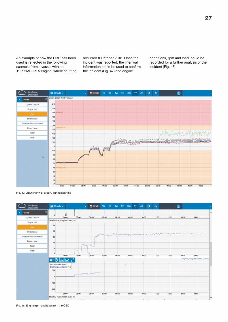
An example of how the OBD has been used is reflected in the following example from a vessel with an 11G95ME-C9.5 engine, where scuffing
occurred 8 October 2018. Once the incident was reported, the liner wall information could be used to confirm the incident (Fig. 47) and engine
conditions, rpm and load, could be recorded for a further analysis of the incident (Fig. 48).
Fig. 47: OBD liner wall graph, during scuffing
Fig. 48: Engine rpm and load from the OBD

MAN Energy SolutionsService experience – two-stroke technologies28
2017R&D test on a commercial G95 engine type on the test bed where TCEV-FBIVs were mounted on three cylinders. Cylinders 1, 2 and 3 are rebuilt to match the TCEV-FBIV Mk. I cylinder control components. The basic TCEV-FBIV design remains unchanged compared to the G95 R&D test in 2016. However, the oil distribution block of the TCEV actuation unit has been redesigned to facilitate faces for mounting of separate hydraulic control valves for the FBIV as well as for TCEV actuation. The two control valves are named ELFI (electronic fuel injection) and PEVA (proportional exhaust valve actuation).
2017A single cylinder TCEV-FBIV Mk. I service test of an 8G95ME engine was launched prior to sea trial of a large container vessel. In March 2018, the test components have been upgraded to Mk. II components.
actuation unit. The abbreviation TCEV is used about the complete exhaust valve, where a piston in a so-called control bushing inside the actuation unit actuates the spindle. The piston in the oil cylinder acts directly on the exhaust valve spindle top. The actuation unit is mounted directly on the exhaust valve housing.
2015Launch of S50ME-C8 single cylinder TCEV-FBIV service test. The component set-up is similar to that of the 4SME-T9 test runs. The FBIV and TCEV designs are of the first type and in this document they are given the designation Mk. I. The hydraulic control valve is of the FIVA type. A shut-off valve is required in the low-pressure fuel supply line to the test cylinder due to the Mk. I FBIV design. The service test was extended after an intermediate inspection of the TCEV-FBIV components during the planned dry-docking of the vessel in the summer 2018.
2016R&D test on a commercial G95-type engine on the test bed where TCEV-FBIVs were mounted on three cylinders. Cylinders 1, 2 and 3 are rebuilt with TCEV-FBIV Mk. I cylinder control components. The basic TCEV and FBIV designs are the same as for the S50ME-C8 engines. However, the change in dimensions for the G95 design makes the two set-ups non-comparable. For the G95 trials, the low-pressure liquid supply and drain line layout for the FBIV are revised in order to ease the mounting and replacement of the FBIV in the cylinder cover. The hydraulic control valve is of the FIVA type.
The purpose of achieving a weight reduction for newly designed engines has led to the development of directly actuated cylinder control components. The weight reduction is around 30% compared to a traditional ME cylinder control arrangement. The direct actuation allows an improvement of the well-proven design used for decades, where high-pressure fuel lines and, to some extent, hydraulic pressure lines transfer forces from the actuator to the fuel injection valve and the exhaust valve. The fuel and exhaust trains consist of the same components as known from the ME/-C engines, however, they are redesigned and relocated.
In the following component description and system layout, the terms fuel booster injection valve (FBIV) and top-controlled exhaust valve (TCEV) will be explained.
Design paths
2012-2014Single cylinder service test of FBIV on S50ME-B, where hydraulic oil is led to the actuation piston of the FBIV by an electronic fuel injection valve (ELFI-valve) directly mounted on the FBIV body (plunger body). Trouble-free service test for 10,000 hours of HFO operation has been obtained (test terminated in 2016).
2014TCEV-FBIV mounted on all cylinders of a 4S50ME-T9 engine for R&D purposes. The FBIV design is similar to that of the S50ME-B with exception of the hydraulic oil supply design. The hydraulic oil is distributed to the FBIV actuation piston from the TCEV
TCEV and FBIV introduction

29
the double-walled hydraulic pipe. The pipe, which lies against the face of the TCEV oil cylinder, transfers pressurised hydraulic oil from the annular-shaped chamber formed by the TCEV control bushing, see Fig. 50, pos. 2 and the oil cylinder pos. 1. This chamber contains distribution oil for all FBIVs installed in the cylinder cover, the chamber is pressurised when the ELFI valve directs hydraulic oil to the chamber.
During the initial S50ME-T9 trials, air bubbles were experienced which tend to accumulate in the hydraulic pipe to the FBIV top cover. In order to ensure that the trapped air causes no disturbances, LPS oil enters the FBIV top cover via a non-return valve (Fig.
chamber. The precision steel pipes connect the FBIV to external fuel supply and fuel return manifold, and LPS oil and umbrella drain (see Fig. 49 pos. 2, 5 and 6).
Low-pressure fuel is supplied to the compression chamber via a suction valve integrated in the fuel plunger (pos. 7). As hydraulic oil is supplied to the top of the hydraulic piston integrated with the fuel plunger, the low-pressure fuel lever is lifted to the FBIV opening pressure and further up to the injection pressure. As the FBIV opens, the fuel injection phase starts.
The FBIV top cover (Fig. 49A and C, pos. 9) facilitates a face for mounting
FBIV component description
The following FBIV component description refers to Fig. 49. A cylindrical sleeve is bolted onto the cylinder cover, concentric to the FBIV bore in the cylinder cover. The inner wall of the sleeve has faces against which the O-rings mounted on the FBIV pump barrel seal (pos. 11). The annular shaped chambers formed when the FBIV is mounted in the sleeve act as pressure and drain collector for fuel and lubrication oil, i.e. low-pressure supply (LPS) oil.
Precision steel pipes are connected to bores, each piercing the sleeve wall in the centre of each annular-shaped
Fig. 49: FBIV development
1
2
3
4
5
7
9
11
10
1
2
3
4
6
7
8
9
11
10
1. Fuel booster plunger combined with hydraulic actuator piston2. Umbrella drain3. Fuel inlet4. Fuel return5. LPS inlet6. LPS return7. Suction valve as integrated part of the fuel booster plunger8. Non-return valve9. Top cover10. Fuel valve cut-off shaft11. Pump barrel
AFBIV Mk I cross-sectional drawing
B CFBIV Mk II cross-sectional drawing
Inlet manifold to cylinder
Fuel manifold side
Fuel cut off valve

MAN Energy SolutionsService experience – two-stroke technologies30
49, pos. 5). The LPS oil flows through the hydraulic double-walled pipe to the TCEV oil cylinder in between two injec-tion phases.
The R&D tests at MAN ES in Copenhagen and the G95 R&D trials at test bed in 2017 demonstrated an improved accuracy of the fuel injection profile (time versus pressure) when LPS oil flowed in the opposite direction, i.e. from the TCEV oil cylinder to the FBIV. The LPS oil inlet in this design goes through a valve block mounted on the outer surface of the oil cylinder. This block connects to the FBIV drain bore of the TCEV oil cylinder. The valve block’s inner slide is actuated by oil flow and returned to
the resting position by a spring force. The slide is actuated in the phase after fuel injection, where the ELFI connects the hydraulic piston in the FBIV to the drain. Once actuated, the LPS inlet bore is closed. When the FBIV fuel plunger has fully returned, the slide will return to its resting position and LPS oil can now flow through the double-walled hydraulic pipe through the FBIV and out through the bore in Fig. 49C, pos. 6.
The Mk. II FBIV has only this type of air bleed. The Mk. II design has a non-return valve (Fig. 49C, pos. 8) built into the outlet bore of the compression chamber formed by the pump barrel and the fuel plunger. The non-return
valve is closed by spring force at around 20 bar pressure and lower in downstream direction. Hereby, any uncontrolled fuel ingress to the combustion chamber is prevented during engine standstill and between two injections if the spindle guide is stuck in the lifted position. A pneumatically operated three-way valve (fuel cut-off valve) is required when running with the Mk. I FBIV, since this design did not have the mentioned non-return valve. The fuel cut-off valve is located in the fuel inlet line to the FBIV, see Fig. 49B, picture.
1. Oil cylinder2. Control bushing (piston or slide contains step 1 and 2 annular surfaces for hydraulic energy control at exhaust valve spindle actuation)3. Hydraulic distribution block4. Inlet for pressurised hydraulic oil 5. ELFI control valve6. PEVA control valve7. Cone for exhaust valve spindle position detection8. Air piston (no opening damper function)9. Air spring chamber safety valve10. Exhaust valve gas housing
ATCEV Mk II cross-sectional drawing
B C3D model of TCEV Mk. II
2
7
8
9
4
1
36
10
Fig. 50: TCEV Mk. II

31
positions of the control bushing and the piston determine on which of the two axially orientated faces the pressurised hydraulic oil will act on. The hydraulic force acts on both faces in the initial opening phase of the exhaust valve spindle. The piston inside the control bushing will change its position relative to the bushing, as the piston pushes the exhaust valve spindle further down. This change in relative position cuts off the hydraulic oil supply to step1. Towards the end of the exhaust valve opening stroke, where the target is to slow down the spindle speed to avoid the so-called overshoot, the relative position of the piston and control bushing throttles the oil flow to step 2.
distribution block, the hydraulic control valves mounted on the block distribute oil to the FBIV during the fuel injection phase. Cylinder scavenging is ensured by directing pressurised hydraulic oil to the oil cylinder of the TCEV actuation unit.
The piston for exhaust valve spindle actuation has two axially oriented faces (Fig. 51, pos. 2 and 3) starting in the top closing damper (Fig. 51, pos. 1) and extends further down. The uppermost face has the smallest cross section, named step 2. The designation used for the larger face is step 1. At the initial opening of the exhaust valve, a high force is required for spindle actuation. The relative
TCEV component decription
As mentioned earlier, the TCEV abbreviation is used about the complete exhaust valve, where a piston in the control bushing inside the actuation unit performs the spindle actuation. The piston in the oil cylinder acts directly on the exhaust valve spindle top. The actuation unit is mounted directly on the exhaust valve gas housing.
A hydraulic distribution block (equivalent to the HCU used on all electronically controlled engines) is mounted on the designated face of the TCEV actuation unit. Pressurised hydraulic oil is supplied to the
Fig. 51: Improved control bushing with slide

MAN Energy SolutionsService experience – two-stroke technologies32
However, at engine part load, where the cylinder pressure is low, throttling the oil flow, controlled by the relative position of the piston and control bushing, is insufficient to slow down the spindle speed. Here, throttling of the oil supply to the actuation unit is required. The PEVA throttles the oil supply due to its proportional characteristics.
In the early period of the ME engine the cylinder control consisted of ELFI and ELVA control valves (2000-2005). Hereafter, the properties of the two valves were merged into a single control valve design (FIVA). In 2016, the ELFI and ELVA control valves became the standard on the newly
designed electronically controlled engines. The ELVA control valve design has no proportional properties and this is required to control the TCEV.
Mk. II design particulars: – The control bushing (Fig. 50, pos. 2 and Fig. 51) has been upgraded in the Mk. II revision with a larger wall thickness of the wall surrounding the piston, which is pushing onto the exhaust valve spindle top. During the finite element analysis (FE analysis), it was discovered that the control bushing was deformed by the impact of the pressurised hydraulic oil.
– The design of the oil cylinder top cover is revised to improve bleeding of trapped air in the FBIV hydraulic actuation pipe. Bleeding and flushing is done between injection phases (FBIV-actuation).
– The oil distribution block of the TCEV actuation unit allows “hanging” hydraulic accumulators.

33
Several shop trials and R&D tests of both small- and large-bore engines with TCEV/FBIV have led to the latest iteration of the G95-TCEV design, which is currently being tested on an 8G95ME-C9.5 engine in service.
As Table 1 shows, 3412 running hours have been accumulated on the Mk. 2 design iteration since it was launched in March 2018. It replaced the intermediate iteration, the Mk. 1.5, which had accumulated 3915 running hours.
1 FIVA-II-60 6/3 was specifically developed for the TCEV design with the addition of an extra port (VAtop) enabling de-pressurising the exhaust valve actuator slide more uniformly on both step-I and step-II annular piston areas. The use of this valve has been cancelled, as there is a tendency to progressively diverge from single-valve mainstage control towards having two mainstages controlling the fuel and exhaust valve, respectively, as standard again. The PEVA valve was developed for the same, including the same VAtop pressure port with the addition of proportional-controlling capabilities compared to the ELVA valve, thus, enabling customised control of the exhaust valve actuation flow including the possibility of performing speed control of the valve spindle.
2 No Mk. 1.5 design officially existed. The rapid out-phasing of the FIVA-II-60 6/3 valve on the design, however, gave birth to the Mk.1.5 version whereas the first 4018 RHs were conducted on the original hardware-design (Mk. 1), but with the ELFI/PEVA valve configuration rather than FIVA-II, see Fig. 52.
3 See Fig. 53.
G95 TCEV service experience
G95ME-C9.5 TCEV/FBIV service hours
Designation Service test start Currently accumulated running hours in service Control valve(s) Injection flushing valveMk. 11 n/a 0 FIVA-II-60 6/3 NoMk. 1.52 August 2017 3915 PEVA-30-15-TCEV & ELFI B3-45 NoMk. 23 March 2018 3412 PEVA-30-15-TCEV & ELFI B3-45 Yes
Fig. 52: TCEV Mk. 1.5
Table 1: Running hours accumulated on service tests
Fig. 53: TCEV Mk. 2

MAN Energy SolutionsService experience – two-stroke technologies34
to jack up the measuring cone against the air piston. Fig. 55 shows fretting and seizing marks inside a cone after removal.
The clearance in the measuring cone was increased on the Mk. 2 test to avoid this issue again.
Stuck measuring cone and fretting of inner surface
On the first inspection (see Table 2), we encountered a few issues with the mea-suring cone positioned on top of the exhaust valve spindle in the Mk. 1.5 design, where the clearance was too tight. As a result, removal of the cone during inspection had to be done by means of threaded studs to jack it up, and hydraulic force applied to the top to push against the spindle top. Fig. 54 shows the process, when using studs
Over the years the TCEV-design has progressively matured during various service tests, therefore a large percentage of the encountered remarks to the entire system have been eliminated. Table 2 highlights the respective focus points and findings of the inspections.
The general behaviour of the TCEV has been steady and satisfactory. Minor remarks were made during the inspections, thus leading to further iterative work on the design.
G95ME-C9.5 TCEV component inspections since the launch of the test
Inspection no. Designation RHs of design at inspection Date Focus point Findings1 Mk. 1.5 1586 November 2017 Air piston and cone rings
conditionFretting and seizing of the measuring cone to the spindle.
2
Mk. 1.5
3915
March 2018/rebuilt to Mk. 2
Rebuilding of unit to Mk. 2., control bushing check
Coke deposits in X/V housing of the TCEV related to the length of the atomisers. Cavitation on control bushing outer rim to step-1 drain chamber.
3 Mk. 2 3147 October 2018 Repeating PEVA alarms during manoeuvring
Cavitation of PEVA slide and configuration of proportional valve.
4
Mk. 2
3412
November 2018
Complete disassembly and inspection of TCEV components
Imprint on top of the measuring cone, worn spindle stem seal and small cavitation marks on the control bushing.
Table 2: G95ME-C9.5 TCEV component inspection
Fig. 54: Stuck measuring cone Fig. 55: Fretting inside the measuring cone

35
Cavitation of control bushing rim towards step 1 cut-off volume
During re-building of Mk. 2 components in March 2018 (see Table 2, second inspection) cavitation was found on the control bushing during assessment of the flow port conditions. Cavitation damage was discovered on the outer-rim above the uppermost sealing ring towards the step-1 cut-off volume. The cavitation location and damage can be seen on Fig. 56.
The mentioned components have been improved on the Mk. 2 design where the flow area of the tank bores from injection and valve actuation have been increased. Additionally, the newest commercialised version of the TCEV has been improved by separating the injection and exhaust valve tank bores.
PEVA feedback alarms and slide cavitation
One of the more long-lasting and repetitive issues is PEVA feedback failure alarms, also referred to in Table 2, third inspection. This issue only pertained during ME manoeuvring, and it was concluded that cavitation and sticking of the PEVA main slide was the cause.
As a rapid test, the PEVAs were cleaned and the slide was rotated 180 degrees, thus, the area with cavitation was no longer directly exposed to the flow from the hydraulic pressure port. After assembly, the engine was tested and no alarms have been returned since then. The design was updated immediately because of the findings and the test vessel received a replacement valve with an updated slide, which is now running to accumulate hours. In order to assist with the production of control valve slides, the PEVAs had another slide design than normally for control valves from the beginning.
Unfortunately, flow cavitation on the rim (between the CVa-port (valve actuation)
Fig. 56: Cavitation on the outside of the tank control bushing
Fig. 57: PEVA slide bearing
Fig. 58: Cavitation on PEVA slide version I Fig. 59: Cavitation on the PEVA housing
and P-port (HPS pressure)) of the slide and counterpart caused the ME engine slow down. The two designs can be seen in Fig. 57.
Fig. 58 shows the cavitation damage on the PEVA slide and Fig. 59 shows the damage on corresponding counterpart of the PEVA housing.

MAN Energy SolutionsService experience – two-stroke technologies36
Remarks from the latest inspection
As mentioned in Table 2, the fourth inspection resulted in a few remarks. The list below and Fig. 60 summarises the findings and the location in the TCEV where these were made. In general, though, apart from the minor remarks, the TCEV Mk. 2 design shows a very stable and equally reliable performance and operation as the low-force exhaust valve.
1. Imprint on top of the measuring cone made by the pressure piece on the actuator slide
2. Worn spindle stem sealing ring3. Cavitation marks on oil cylinder and
control bushing4. Condition of seals on control
bushing and top cover5. Sticking of measuring cone
When the measuring cone was removed from the spindle top, an indentation on the diameter of the actuator slide pressure piece was discovered. The measured depth was 0.35 mm as seen on Fig. 61.
The stem seal was worn down by 23% during the clocked running hours. As a result, the amount of coke deposits inside the spindle guide and air spring chamber were higher than normal. A cause of ring wear can be a too small amount of oil in the controlled oil level (COL) and therefore a lack of preservation of the ring during operation. This may be solved by tuning the safety valve which controls the air
Fig. 60: Minor issues with TCEV Mk. 2
Fig. 61 Imprint from actuator slide pressure piece Fig. 62: Air spring chamber Fig. 63: Coke deposit in the spindle guide
1
53+4
3+4
2
pressure and oil leakage in and from the air spring COL.
Figs. 62 and 63 display the increased debris in the air spring chamber and the amount of coke deposits in the
spindle guide clearance, respectively.
Small cavitation marks were found on the same rim towards the step 1 cut-off drain volume, but to a lesser degree than found at the Mk. 1.5. The

37
improvement is a result of the increased flow area of the tank bores in the TCEV Mk. 2 design. These bores are also con-nected directly to the step 1 cut-off drain volume around the control bushing. The cavitation marks are highlighted with a white circle on Fig. 64, a greatly improved situation compared to the previous design. The commercialised TCEV version has already been further improved by separating the tank bores from injection and exhaust valve, TFi and TVa respectively.
The radial sealing rings on the control bushing were found with some degree of wear, most likely due to the relative motion of the bushing. This is solved in the next iteration by fixating the bushing from the top of the TCEV oil cylinder. In the Mk. 2 version it is kept in place by the TCEV top cover allowing a few tenths of millimetres vertical motion. Fig. 65 displays the wear of the sealing rings.
Fig. 64: Imprint from actuator slide pressure piece
Fig. 65: Sealing ring wear

MAN Energy SolutionsService experience – two-stroke technologies38
Operational issues
All springs were in good condition without any sign of breakage only minor marks on the outer surface of the windings were noticed. It is likely that these marks arose because the windings have been touching the inside of the fuel valve holder.
At an early stage, we saw peel-off of coated material from the inlet hole opening of the suction valve (shown with circles on Fig. 67). The previous design had sharp edges in the oval opening of the suction valve. When the plunger went through a nitrating process, the entire sharp edge around the opening would be fully nitrated and not just surface-coated. This edge would be extremely brittle and not able to withstand the flexing of the plunger
integrated on one unit was chosen (illustration in Fig. 66). The service test was initiated with FBIV Mk. 1 design in August 2017, the test is still ongoing but the FBIV has been upgraded to Mk. 2 design.
In March 2018, we implemented Mk. 2 with several changes to the design. The most crucial was a non-return valve, now implemented inside the FBIV between the plunger/barrel and fuel valve thrust piece. This was done to remove the possibility of pouring fuel into the combustion chamber if the spindle guide was hanging. Other changes were made to the appearance and design of the plunger.
After 3,147 running hours some issues are known for the FBIV Mk. 2, which will be covered in the following.
FBIV in general
The development of the FBIV started as a single cylinder test on a 6S50ME-B9.2 engine in March 2014. The unit accumulated more than 10,000 running hours without components malfunctioning. The unit ran continuously on HFO without any issues, and the service test was terminated in March 2016. After the success, a more extensive service test was initiated in February 2016 on an S50ME-C8.1 single unit combined with TCEV and the test is ongoing. In December 2018, the unit clocked 6,000 running hours on MGO.
As the FBIV development progressed, it was necessary to test the design on a large-bore engine. Therefore, an 8G95ME-C9.5 with TCEV/FBIV
Fig. 66: Three units with TCEV/FBIV on an 8G95ME-C9.5 engine Fig. 67: Inlet hole of suction valve
G95 FBIV service experience

39
experienced during an injection. The issue has been solved by rounding the edge in the oval opening.
Cavitation marks appeared on top of the hydraulic plunger. The marks clearly occurred 90 degrees apart, see Fig. 68. This confirms our suspicion about too few pressure relief grooves on top of the hydraulic plunger.
Design changes have been implemented to solve the issue on future designs. Additional relief grooves have been created, see the illustration in Fig. 69.
Maintenance issues
Several incidents occurred during testing and in service when the FBIV was dismantled. The fuel valve holder nut, which secures the spindle guide to the fuel valve body, breaks the guide pin for the atomiser. When dismantling the FBIV a torque is applied which supersedes the limits of the atomiser guide pin. The excess force is needed due to large friction and a high tightening torque. The design has been updated to a two-piece divided fuel valve holder nut and the tightening torque has been reduced.
The test vessel where the TCEV/FBIV testing was conducted experienced a breakdown at sea due to a broken O-ring. The failure pointed at additional challenges related to the FBIV design.
The FBIV is mounted in a sleeve, which is protruding from the cylinder cover, see Fig. 70. This sleeve has a relief hole to prevent pressure build-up in case the fuel valve does not seal properly against the seat in the fuel valve pocket.
When the O-ring snapped, the fuel outlet compartment had access to fuel oil return and fuel was spraying up against the exhaust valve housing. Subsequently, the crew attempted to overhaul the FBIV, which resulted in a complete failure of the FBIV due to a
Fig. 68: Cavitation marks on the hydraulic plunger top
Fig. 70: FBIV design in the cylinder cover
Fig. 69: Plunger top with the modified grove design
Fig. 71: Wrong assembly of fuel valve part and pump barrel
disastrous mounting of the FBIV in the top cover.
This incident revealed the vulnerability of the design related to assembly of the fuel valve part and the pump barrel. Guide pins, which can be difficult to align, can create an uneven load distribution between thrust piece and barrel. In this case the mentioned components were crushed, see Fig. 71.

MAN Energy SolutionsService experience – two-stroke technologies40
Fig. 72 shows top cover, barrel, guide bushing and the fuel valve part. From the left, the top cover is mounted on the barrel with a heavy-duty guide pin, which leaves only one mounting solution. The bushing is mounted on the barrel and acts as a guide for the fuel valve. All three parts have an asymmetric mating part for easy assembly.
The spindle guide is fabricated with a knot, see Fig. 73. The knot replaces the guide pin, which is prone to breakage. The new knot design has chamfered round edges, which creates a stronger and more resilient design. All of these changes will be implemented in the coming design.
Furthermore, the mounting bracket was twisted out of alignment with the pin, when it was mounted in the cylinder cover. The design can cause the mounting bracket to be twisted out of alignment and create a potential risk of an incorrect injection angle into the combustion chamber.
Updated design
To eliminate the possibility of wrong assembly and mounting, we have reduced the number of small vulnerable guide pins and created heavy-duty guides with asymmetric shapes.
Fig. 72: Updated design of FBIV assembly
Fig. 73: Updated spindle guide knot design

41
pressure, where the cut-off shaft lifts from its seat and injects oil.
In the CR injection, valve pressurised fuel enters the space above the cut-off shaft via control bores, and it will create a downwards force on top of the cut-off shaft, thus keeping it firmly against its mating seat of the spindle guide housing.
When an injection command is given, the control valve inside the CR-injection valve is energised. The control valve needle lifts and connects the chamber above the cut-off shaft to the return line manifold of the engine (4 bar system). The cut-off shaft lifts from its seat and injection starts. When the injection STOP command is given, the control valve is de-energised and the needle in the control valve seals off the chamber above the cut-off shaft. The fuel pressure above the cut-off shaft raises to the rail pressure and the created force moves the cut-off shaft firmly against its seat in the spindle guide housing.
In the event that the spindle guide malfunctions, a built-in flow limiter will close, thus preventing fuel from flowing uncontrolled into the cylinder space. The capacity of the flow limiter is 130% of the required fuel amount in load point L1. A recirculation valve of the mechanical type is built into the CR-injection valve top cover. The recirculation valve is opened by a spring force when the fuel pressure drops to less than 15 bar fuel pressure.
positioned so that the rail pressure stabilises at 700-900 bar. The flow out of the COMBI valve determines the specific rail pressure. The largest flow out of the COMBI valve happens at low engine load and vice versa.
The situation where the COMBI valve is opened by spring force is called “limp home” condition. The engine can be operated at reduced load in this condition until the loss of rail pressure control can be rectified. The COMBI valve will only open mechanically (safety valve function) if the high-pressure pump index control goes into the fail-safe mode.
High-pressure fuel pumpThe pump (see Fig 74–3) is of the reciprocating piston type, i.e. with positive displacement. The pump is driven by an electric motor powered by a variable frequency drive (VFD) (see Fig. 74–4). The reason for the VFD-controlled power supply is to keep the pump shaft rotation speed at the specified 3000 rpm regardless of the supply grid frequency.
The delivered amount of fuel from the pump is controlled by a control unit (throttle valve) mounted in front of the suction side of the pump. The control unit is of the electrical/mechanical type. A spring force returns the valve to fully open position (full index) and the force from an electric coil performs the throttling of the fuel amount to the pump.
The common rail system is designed for preheated HFO operation, i.e. fuel oil will be circulated through the high-pressure pumps and CR injection valves in all conditions independent of the engine fuel consumption.
Common rail injection valveThe CR injection valve (see Fig. 74–5) is continuously exposed to the rail pressure, which always acts on the lower side of the cut-off shaft like in a conventional fuel valve, where a compressed spring determines the
Fuel railThe rail (see Fig. 74–1) is a single-walled tube pressurised by a number of high-pressure fuel pumps in the standard fuel supply system in the engine room. The pumps are controlled by the ECS and each high-pressure pump connects to the rail via a double-walled pipe and a non-return valve.
The fuel supply for each common rail injection valve (CR valve) happens via a flow limiter built into the rail connection block bolted onto the top surface of the rail. The flow limiter has a capacity of 150% of the required amount of fuel at load point L1.
The fuel rail is equipped with two COMBI valves, which act as mechanical safety valves and as an operational rail pressure control (digital), when the engine mode changes from STOP to RUNNING to STOP. If mechanical activation takes place from the ECS due to a loss of rail pressure, normally just one of the two opens.
Rail pressure transmitters PT1, PT2 and PT3 are connected to the rail at its aft end and at the same position to minimise sensor deviations caused by potential pressure pulsation in the rail, thus stabilising rail pressure control.
COMBI valveThe COMBI valve (see Fig. 74–2) is mounted in the rail connection block. Firstly, its purpose is to act as a mechanical safety valve. Secondly, it can be opened by compressed air via the ECS. Actuation via the ECS is used when the engine operational state changes from STOPPED to RUNNING condition.
A pre-set spring force causes the COMBI valve to open at 1,150-1,200 bar. This pressure acts on an internal needle with an annular-shaped face, when combined with a narrow gap in front of the outlet bore of the COMBI valve body, the needle will be
Common rail system description

MAN Energy SolutionsService experience – two-stroke technologies42
1 2 3 4 5 6 7 8
2 2
3 3
5
3 4 5
6
2
1
34
25
Fig. 74: Common rail design on 6S35ME-C9-CR
1. Fuel rail2. COMBI valve3. HP pump4. VFD drive5. CR injection valve6. CRISD module

43
CRISD moduleEnergisation of the CR injection valve coil happens via an amplifier module, termed the CR injection system driver, CRISD (see Fig. 74–6). The CRISD module is powered and controlled by the cylinder unit multi-purpose controller (MPC). When an injection command is given, a relatively high pull-in current (see Fig. 75) is required to lift the control valve piston. After the initial lift, a lower hold-in current is sufficient to keep the control valve piston lifted and hence the CR injection valve open during the rest of the
Pull-in
Hold-in
Trig input
Time [S]
Trig input [V]
Output current [A]
HW interrupted max time
Fig. 75: Solenoid current profile
injection cycle. The output voltage during pull-in is 100 VDC and the current control takes place with the pulse width modulation (PWM) technique.
Low-pressure fuel supplyFuel is supplied to the HP pumps through 50µ and 6µ filter units in series, both are of the auto-backflush type.
Lubricating oil supplyLubricating oil supply for each HP pump branches off from the LPS system manifold of the engine, the
pressure is increased to the pressure specified by the manufacturer by means of a mechanically driven lube oil pump directly connected to the HP pump crankshaft.
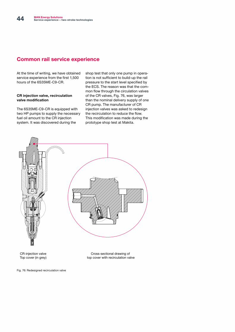
MAN Energy SolutionsService experience – two-stroke technologies44
At the time of writing, we have obtained service experience from the first 1,500 hours of the 6S35ME-C9-CR.
CR injection valve, recirculation valve modification
The 6S35ME-C9-CR is equipped with two HP pumps to supply the necessary fuel oil amount to the CR injection system. It was discovered during the
Fig. 76: Redesigned recirculation valve
Common rail service experience
CR-injection valveTop cover (in grey)
Cross-sectional drawing of top cover with recirculation valve
shop test that only one pump in opera-tion is not sufficient to build-up the rail pressure to the start level specified by the ECS. The reason was that the com-mon flow through the circulation valves of the CR valves, Fig. 76, was larger than the nominal delivery supply of one CR pump. The manufacturer of CR injection valves was asked to redesign the recirculation to reduce the flow. This modification was made during the prototype shop test at Makita.

45
In the process of redesigning the recirculation valve it was discovered that the pressure drop of approximately 4 bar across the stopped HP pump was too large (see Fig. 77A). Consequently, the HP pump manufacturer was asked to reduce the pressure drop across the pump which they solved by inserting an external bypass line in series with a built-in upstream non-return valve (Fig. 77B).
Modification of HP pump pressure control valve
Apart from experience gained during shop test, the intake throttle, Fig. 78A, in combination with a standard two-stage fuel supply system used in HFO applications, caused too low pressure in the inlet manifold of the engine.
The low-pressure problem was experienced during sea trial, and it was temporarily solved by increasing the spring force within the intake throttle. The permanent solution was to replace the intake throttle with an orifice with fixed bore (Fig. 78B).
Originally, the HP pump was delivered with pneumatic activation (closing) of the intake throttle (Fig. 78A) to enhance fuel circulation through the stopped pump. With the fixed bore orifice as the permanent successor to the pressure control valve, the pneumatic activation had no function and it was omitted in the final layout (Fig. 78B).
COMBI valve experience
An issue occurring for an engine running with open COMBI valve was discovered during the preliminary test run. The COMBI valve opened as intended at high rail pressure, but the normal reset function of the COMBI valve did not function correctly. The COMBI valve is reset correctly by stopping the engine and reducing the rail pressure to a level below the COMBI valve reset value (<240 bar). Consequently, it was suggested to include digital position monitoring of
Fig. 77: High-pressure pump redesign
B
Initial situation
Solution
A

MAN Energy SolutionsService experience – two-stroke technologies46
Fig. 78A and B: Control diagrams for the high-pressure pump
Optimal check-valve to bypass the pump during spilling process
High pressure pumpwith control unit
Lube oil booster systemEngine
MP06
MP04
Fine filter (5μm)
Pre-filter (25μm)
MP03
Fuel
feed
line
MP01
Fuel
retu
rn li
ne
Lube
oil
feed
ing
line
Lube
oil
retu
rn li
neto
tank
Lubrication pointsof HDP-K3
MP02
Inje
ctor
retu
rn li
ne
Plunger leackage returnline (unpressurized)
Flow control valve,solenoid-operated
MP05Drain throttleØ1 mm
Intake throttle
Mix
oil
Sepe
ratio
nre
turn
line
to s
ludg
e ta
nk (u
npre
ssun
ized) Solenoid with piping and
control removed
PI-diagram 2. Hydraulic diagram from maiden voyage,
ECS SW version 1710-2.2
B
High pressure pumpwith control unit
Lube oil booster systemEngine
MP06
MP04
Fine filter (5μm)
Pre-filter (25μm)
MP03
Fuel
feed
line
MP01
Com
pres
sed-
air l
ine
for i
ncre
asin
gpr
essu
re (H
FO s
pill
proc
edur
e)
Fuel
retu
rn li
ne
Lube
oil
feed
ing
line
Lube
oil
retu
rn li
neto
tank
Lubrication pointsof HDP-K3
MP02
Inje
ctor
retu
rn li
ne
Plunger leackage returnline (unpressurized)
Flow control valve,solenoid-operated
MP05Admission pressurecontrol valve
Intake throttle
Pneumatic 3/2-way solenoid valve controlled by the ECS
A
PI-diagram 1. Hydraulic diagram from shop test,
ECS SW version 1710-1.5

47
inspection, breakage of the control valve piston collar/shoulder (Fig. 80, pos. A) was discovered. As it could be expected, the disturbance in the magnetic flux caused by the collar breakage gave current transient peaks in the driver outlet channel. These current peaks were detected by the driver supervision as a fault condition.
Due to the 100 VDC, the output for each CR injection valve is galvanic isolated in order to protect the main circuit board of the CRISD module.
Numerous intermittent driver shutdown alarms occurred during the maiden voyage. The shutdown condition was reset automatically within a few seconds. The extensive troubleshooting finally pointed at a faulty CR injector instead of the driver module, which initially was suspected to be the root cause. At an open-up
the COMBI valve needle along with the introduction of a position sensor on the COMBI valve top cover. A redesigned top cover was introduced (Figs. 79, pos. 4 and 12). Sensor calibration is performed to achieve a correct position feedback signal to the ECS (ECS SW parameter).
CR injection valve
The CRISD driver supervises internal board circuits and external outputs.
Fig. 79: Combi valve redesign
Fig. 80: CR injection valve and control valve

MAN Energy SolutionsService experience – two-stroke technologies48
Three control valve pistons broke after 300 hours of operation, Fig. 81.
A finite element (FE) calculation was performed to understand the reason behind the rupture. The following modifications have been introduced (Fig. 82) based on the results:
– Shoulder thickness increased to 2 mm
– Relief radius changed to 0.4 mm – Material changed from HS-6-5-2 to Vanadis 4E
– The fatigue limit of Vanadis 4E is twice that of HS-6-5-2.
A complete set of CR injection valves with the improved control valve piston collar was produced, delivered on board and installed in the engine by the end of November 2018. By mid-March 2019 the batch of new injection valves will have been in service for 1,100-1,200 hours. No problems have been reported within the service period.
Fig. 82: Modified design of CR injection control valve collar
Fig. 81: Broken CR injection control valve collar
First piston got broken after around 300 hours
Second piston got broken few hours after the first

49
The amount of sludge and dirt accumulated in the scavenge air receiver is increased in EGR operation compared to operation without EGR, Fig. 84. The feedback from owners operating continuously with EGR or EcoEGR is that the cleaning interval has been slightly reduced.
One concern about EGR operation, related to service experience, has been the cylinder condition and the amount of cylinder oil required to maintain a good wear condition and clean piston ring lands. Again, in order to have sufficient service hours we have inspected the EcoEGR engine after approx. 1,000 EcoEGR hours and 100 EGR hours. Figs. 85 and 86 show piston rings, piston top land, piston skirt and cylinder liner for cylinder 1
The Tier III technologies, EGR and SCR, are introduced in large numbers on vessels being commissioned these days. However, service hours from the vessels operating in Tier III mode are still limited because of the limited operating hours in ECA zones. The general feedback from owners of vessels with EGR or SCR is good, but based on a limited number of service hours.
In 2018, we introduced the Tier II version of the EGR system, the EcoEGR. EcoEGR is used in Tier II mode with a 10-15% recirculation rate, see Fig. 83. On 7G80ME-C9.5-EGRTC-Eco, the feedback after 1,000 EcoEGR service hours is good and the cylinder condition acceptable operating continuously on HFO.
Tier III technologies
Fig. 83: EGR and EcoEGR
35-40%Exh. gas coolingCleaningrecirculating
Tier III operation:NOX < 3.4 g/kWh
Tier II operation:NOX < 14.4 g/kWh
10-15%Exh. gas coolingCleaningrecirculating
and 5, respectively, in very good condition.
The cylinder oil sweep test in EcoEGR mode (Fig. 87) shows a feed rate factor of 0.32 g/kWh*S%, which is quite normal for this engine type.
There is an increased interest in combined scrubber and Tier III plants. The general scrubber market is booming and the scrubber makers have full order books, even well into 2020. All shipping segments are now choosing scrubbers however, the largest segments are cruise ships, RoRo, bulk carriers and container vessels. The estimated number of scrubber ships by 2020 is 3,000-4,000, depending on the source (retrofit around 70%, newbuildings 30%).
Fig. 84: Sludge and dirt accumulation in the scavenging receiver when operating with EGR

MAN Energy SolutionsService experience – two-stroke technologies50
Fig. 85: 7G80ME-C9.5 EGRTC-Eco, good condition of cylinder No. 1
Fig. 86: 7G80ME-C9.5 EGRTC-Eco, good condition of cylinder No. 5
Fig. 87: Result of cylinder oil sweep test in EcoEGR mode
160
FE average
BN average
140
120
100
80
60
40
20
00.25 0.30 0.35 0.40 0.45 0.550.50 0.600.20

51
Service experience for new designs related to exhaust valve actuation, fuel injection and engine control has been described with the TCEV/FBIV technology and the common rail technology as examples. Furthermore, service experience with regard to our Tier III solutions has been touched upon.
This paper clearly demonstrates our tradition of being very open regarding service experience, both in relation to well-established technologies as well as to new groundbreaking technologies. We are confident that this tradition is highly appreciated by the market, and look forward to continuing the dialogue on service experience with our customers.
With the 11G95ME-C9.5 fleet as an example, advanced tools, many related to the analysis of data collected online, the development of the cylinder condition has been described.
The collection of data from engine operation has become much easier and the amount of data is large and will be even larger. This makes it possible to identify factors not previously known with an influence on the scuffing incidents. An example is the supervision of the engines during sea trial, which clearly showed proof of the impact from rudder movement, and the need to implement additional features in the engine control system.
As an industry, we are continuously challenged to find ways to reduce our environmental footprint, our fuel consumption and CO2 emission. We have introduced engines with a changed combustion process operating on new fuel types to secure lower emissions of NOX and SOX.
To adapt to these changes a close relationship between engine builders, shipowners and us as engine designer is of great importance to address the new challenges once the engines are in service.
In this paper, we have addressed the challenges and solutions regarding the ME-GI technology with an engine and fuel gas supply system perspective.
Conclusion

MAN Energy Solutions 2450 Copenhagen SV, DenmarkP +45 33 85 11 00F +45 33 85 10 [email protected]
All data provided in this document is non-binding. This data serves informational purposes only and is not guaranteed in any way. Depending on the subsequent specific individual projects, the relevant data may be subject to changes and will be assessed and determined individually for each project. This will depend on the particular characteristics of each individual project, especially specific site and operational conditions.
Copyright © MAN Energy Solutions. 5510-0238-00ppr Jul 2019. Printed in Denmark.