SERVICE COMPONENT INVESTIGATION REPORT · PDF fileservice component investigation report...
38
REPORT NO: SCIR 64628 Iss 3 ISSUED BY ROLLS ROYCE PLC SERVICE ENGINEERING SERVICE COMPONENT INVESTIGATION REPORT OPERATOR : SINGAPORE AIRLINES ENGINE TYPE : TRENT SUBJECT: ESN51067 – HP Compressor Lining Loss Investigation ENGINE/MODULE DETAILS PART DETAILS ENGINE MARK TRENT 800 ATA REF 72-41-41 ENGINE NO 51067 MOD STD SEE PAGE 2 MODULE NO FM9795 PART NO SEE PAGE 2 REMOVAL DATE 25 AUG 04 SERIAL NO NA AIRCRAFT/POSITION 9V-SYB POS 1 MATERIAL SEE PAGE 2 LIFE : ENGINE MODULE LIFE : TSN 15614 17488 TSN SEE PAGE 2 CSN 4527 4935 CSN SEE PAGE 2 TSR 2256 2256 TSR SEE PAGE 2 CSR 614 614 CSR SEE PAGE 2 REFERENCES PART CONDITION MRA SPIN PS 7609 SERVICEABLE (Subject to inspection) RECEIPT DATE 28 SEPT 04 REPAIRABLE SEE PAGE 2 RECEIVED FROM company A SCRAP SEE PAGE 2 REPORT REF MFR43255 RETURN TO OPERATOR NAME SIGNATURE DATE COMPILED Roll-Royce plc On file 3 rd April 2006 APPROVED Roll-Royce plc On file 3 rd April 2006 Internal Circulation - This document is the property of Rolls-Royce PLC and may not be copied or used for any purpose other than that for which it is supplied without the written authority of Rolls-Royce PLC ©2006 Rolls-Royce plc. The information in this document is the property of Rolls-Royce plc and may not be copied, or communicated to a third party, or used for any purpose other than that for which it is supplied, without the express written consent of Rolls-Royce plc. Page 1 of 38
Transcript of SERVICE COMPONENT INVESTIGATION REPORT · PDF fileservice component investigation report...

REPORT NO: SCIR 64628 Iss 3
ISSUED BY ROLLS ROYCE PLC
SERVICE ENGINEERING
SERVICE COMPONENT INVESTIGATION REPORT
OPERATOR : SINGAPORE AIRLINES ENGINE TYPE : TRENT
SUBJECT: ESN51067 – HP Compressor Lining Loss Investigation
ENGINE/MODULE DETAILS PART DETAILS
ENGINE MARK TRENT 800 ATA REF 72-41-41 ENGINE NO 51067 MOD STD SEE PAGE 2 MODULE NO FM9795 PART NO SEE PAGE 2 REMOVAL DATE 25 AUG 04 SERIAL NO NA AIRCRAFT/POSITION 9V-SYB POS 1 MATERIAL SEE PAGE 2 LIFE : ENGINE MODULE LIFE : TSN 15614 17488 TSN SEE PAGE 2 CSN 4527 4935 CSN SEE PAGE 2 TSR 2256 2256 TSR SEE PAGE 2 CSR 614 614 CSR SEE PAGE 2
REFERENCES PART CONDITION
MRA SPIN PS 7609 SERVICEABLE (Subject to inspection)
RECEIPT DATE 28 SEPT 04 REPAIRABLE SEE PAGE 2
RECEIVED FROM company A SCRAP SEE PAGE 2
REPORT REF MFR43255 RETURN TO OPERATOR
NAME SIGNATURE DATE
COMPILED Roll-Royce plc On file 3rd April 2006
APPROVED Roll-Royce plc On file 3rd April 2006
Internal Circulation - This document is the property of Rolls-Royce PLC and may not be copied or used for any purpose other than that for which it is supplied without the written authority of Rolls-Royce PLC
©2006 Rolls-Royce plc. The information in this document is the property of Rolls-Royce plc and may not be copied, or communicated to a third party, or used for any purpose other than that for which it is supplied, without the express written consent of Rolls-Royce plc. Page 1 of 38

REPORT NO: SCIR 64628 Iss 3 CONTENTS PAGE 1.0 INTRODUCTION ......................................................................................................................................4 2.0 CONCLUSIONS.........................................................................................................................................5 3.0 PART DETAILS.........................................................................................................................................5 4.0 ROTOR PATH LINING DETAILS .........................................................................................................6 5.0 INVESTIGATION......................................................................................................................................6
5.1 HP COMPRESSOR LINING LABORATORY INVESIGATION ..........................................6 5.1.1. VISUAL EXAMINATION ..........................................................................................6 5.1.2 EVALUATION (REPLICATION) OF ABRADABLE LOSS ..................................6 AND WEAR PROFILE 5.1..3 METALLOGRAPHY EXAMINATION ...................................................................7 5.1.4 SCANNING ELECTRON MICROSCOPY ...............................................................7
5.2 COMPANY B PROCESS INVESTIGATION ..........................................................................9
5.2.1 COMPANY B SPRAYING PRACTICE ....................................................................9 5.2.2 SPRAYING METHOD .................................................................................................9 5.2.3 SPRAYING OF ENGINE 51067 HP COMPRESSOR CASINGS..........................10 5.2.4 SPRAYING OF TEST AND HARDNESS SAMPLES ............................................10 5.2.5 HARDNESS TESTING ............................................................................................. 10
6.0 HP COMPRESSOR ROTOR BLADE CONDITION...........................................................................11
6.1 HP COMPRESSOR ROTOR BLADE TIP MEASUREMENTS ...........................................12
7.0 DIGITAL FLIGHT DATA RECORDER (DFDR) ANALYSIS ..........................................................12 8.0 LH UPPER FAIRING RELEASE ..........................................................................................................12
9.0 DISCUSSION ..........................................................................................................................................13 9.1 HP ROTOR BLADES ................................................................................................................13 9.2 HP COMPRESSOR ROTOR BLADE TIP CLEARANCES .................................................13 9.3 ROTOR PATH LININGS ..........................................................................................................14 9.4 SPRAY PROCESS INVESTIGATION ....................................................................................15 9.5 SERVICE MANAGEMENT ....................................................................................................15
10.0 REFERENCES .......................................................................................................................................15 11.0 GLOSSARY OF TERMS.......................................................................................................................15 ©2006 Rolls-Royce plc. The information in this document is the property of Rolls-Royce plc and may not be copied, or communicated to a third party, or used for any purpose other than that for which it is supplied, without the express written consent of Rolls-Royce plc. Page 2 of 38

REPORT NO: SCIR 64628 Iss 3 12.0 ADDENDUM ..........................................................................................................................................16
12.1 PRAXAIR SURFACE TECHNOLOGIES INVESTIGATIONS..................................................16
12.1.1 ESN51067 – SECTION OF HP COMPRESSOR STAGE 6 CASING ..............................16
12.1.2 ESN51363 – HP COMPRESSOR STAGE 6 CASING .......................................................16
12.1.3 FOLLOW-UP INVESTIGATION BY ROLLS-ROYCE....................................................16
12.1.3.1 EXAMINATION OF CORRECT QUALITY CONTROL SAMPLES .................16 …………FROM 51067
12.1.3.2 PHASE DISTRIBUTION OF STAGE 6 COATING ...............................................16 MICRO STRUCTURE FROM 51363
12.1.4 FOLLOW-UP INVESTIGATION DISCUSSION ..............................................................17
13.0 ADDENDUM 2 .......................................................................................................................................19
©2006 Rolls-Royce plc. The information in this document is the property of Rolls-Royce plc and may not be copied, or communicated to a third party, or used for any purpose other than that for which it is supplied, without the express written consent of Rolls-Royce plc. Page 3 of 38

REPORT NO: SCIR 64628 Iss 3 1.0 INTRODUCTION 1.1 INITIAL ISSUE
Data Systems and Solutions (DS&S) issued an alert for 51067 on 04 August 2004 following a step change in TGT margin. Trouble-shooting was carried out on the engine in accordance with the aircraft maintenance manual (AMM). No anomalies were reported (note: inspection of the rotor path linings is only possible to a very limited extent) and the engine was allowed to remain in service. On 25 August 2004 the engine surged just before V1, after rotation and during climb out of Melbourne. The engine was shut down and an air turn-back was performed after dumping fuel. As a consequence, this event became the subject of an investigation by the Australian Transport Safety Board (ATSB). The ATSB requested that a borescope inspection of the HP compressor and HP turbine blades be carried out. A visual inspection of the VSV stage 1 and 2 levers was also requested. The borescope inspection revealed very minor leading edge damage to a small number of HPC stage 6 blades. All VSV levers were intact but upon opening up the ‘C’ ducts, it was revealed that the left hand upper composite fairing had released from it’s fixing points. The ATSB are carrying out their own investigation on the fairing. The engine was stripped and examined at an appropriate overhaul base (company A). Strip of the 04 module revealed visible lining loss on all six stages of the HP compressor. The lining loss was severe at the rear stages. The casings were returned to R-R, Derby for investigation. This report details the examination findings. The engine had been refurbished at an overhaul base in 2003 using a new HP compressor stage 1 casing and re-lined HP compressor stage 2 to 6. The stage 2 to 6 casings had been re-lined during October 2003 by the overhaul bases sub contractor (company B), based at the overhaul facility.
1.2 ISSUE 2 Since the initial issue of this report, it has been established that incorrect quality control (QC) samples were supplied to, and therefore investigated by, Rolls-Royce. ESNs 51067 and 51092 had both previously been into an overhaul base in May 2002. The HP compressor casings from 51092 were relined by company B and fitted into 51067 at that shop visit. Company B record the ESN for which the casings have been removed, therefore, the correct QC samples to support the investigation were those identified as ‘51092’ not ‘51067’.
COMPANY C carried out an investigation on the following: 1. A section of the HP compressor stage 6 casing from 51067 supplied by Rolls-Royce and the correct QC samples 2. The HP compressor stage 6 casing and QC samples from 51363 (another lining loss casing re-lined by company B). On completion of their investigation, company C sent the correct QC samples to Rolls-Royce for investigation. Company C has now issued their own report (ref Technical Note No.05-14), which concurs with the Rolls-Royce investigation findings but suggests that the lining loss erosion has been caused by a different mechanism.
©2006 Rolls-Royce plc. The information in this document is the property of Rolls-Royce plc and may not be copied, or communicated to a third party, or used for any purpose other than that for which it is supplied, without the express written consent of Rolls-Royce plc. Page 4 of 38
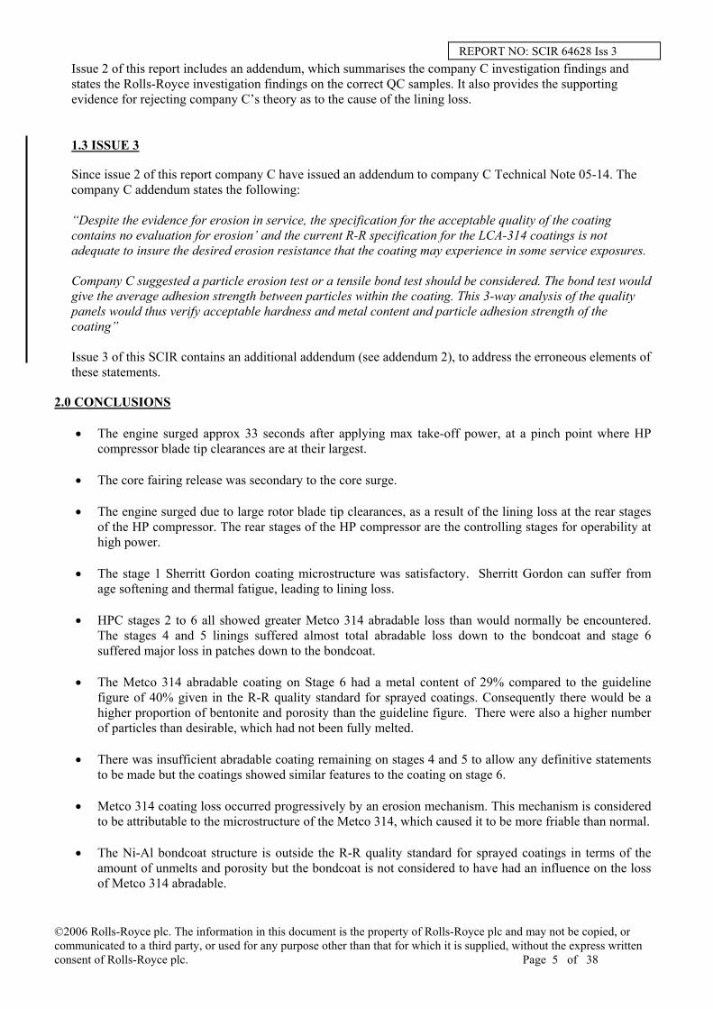
REPORT NO: SCIR 64628 Iss 3 Issue 2 of this report includes an addendum, which summarises the company C investigation findings and states the Rolls-Royce investigation findings on the correct QC samples. It also provides the supporting evidence for rejecting company C’s theory as to the cause of the lining loss. 1.3 ISSUE 3 Since issue 2 of this report company C have issued an addendum to company C Technical Note 05-14. The company C addendum states the following: “Despite the evidence for erosion in service, the specification for the acceptable quality of the coating contains no evaluation for erosion’ and the current R-R specification for the LCA-314 coatings is not adequate to insure the desired erosion resistance that the coating may experience in some service exposures. Company C suggested a particle erosion test or a tensile bond test should be considered. The bond test would give the average adhesion strength between particles within the coating. This 3-way analysis of the quality panels would thus verify acceptable hardness and metal content and particle adhesion strength of the coating” Issue 3 of this SCIR contains an additional addendum (see addendum 2), to address the erroneous elements of these statements.
2.0 CONCLUSIONS
• The engine surged approx 33 seconds after applying max take-off power, at a pinch point where HP compressor blade tip clearances are at their largest.
• The core fairing release was secondary to the core surge.
• The engine surged due to large rotor blade tip clearances, as a result of the lining loss at the rear stages
of the HP compressor. The rear stages of the HP compressor are the controlling stages for operability at high power.
• The stage 1 Sherritt Gordon coating microstructure was satisfactory. Sherritt Gordon can suffer from
age softening and thermal fatigue, leading to lining loss.
• HPC stages 2 to 6 all showed greater Metco 314 abradable loss than would normally be encountered. The stages 4 and 5 linings suffered almost total abradable loss down to the bondcoat and stage 6 suffered major loss in patches down to the bondcoat.
• The Metco 314 abradable coating on Stage 6 had a metal content of 29% compared to the guideline
figure of 40% given in the R-R quality standard for sprayed coatings. Consequently there would be a higher proportion of bentonite and porosity than the guideline figure. There were also a higher number of particles than desirable, which had not been fully melted.
• There was insufficient abradable coating remaining on stages 4 and 5 to allow any definitive statements
to be made but the coatings showed similar features to the coating on stage 6.
• Metco 314 coating loss occurred progressively by an erosion mechanism. This mechanism is considered to be attributable to the microstructure of the Metco 314, which caused it to be more friable than normal.
• The Ni-Al bondcoat structure is outside the R-R quality standard for sprayed coatings in terms of the amount of unmelts and porosity but the bondcoat is not considered to have had an influence on the loss of Metco 314 abradable.
©2006 Rolls-Royce plc. The information in this document is the property of Rolls-Royce plc and may not be copied, or communicated to a third party, or used for any purpose other than that for which it is supplied, without the express written consent of Rolls-Royce plc. Page 5 of 38

REPORT NO: SCIR 64628 Iss 3 • The microstructure of the abradable on the casings was inferior to that produced on the quality control
test samples sprayed with the components. The hardness of the test samples were within the required limits of 45-55R15Y and the microstructure contained 38% metallic phase compared with the recommended value of 40%.
• Rolls-Royce strongly reject the company C assertion in the addendum to company C Technical Note 05-14 that the Rolls-Royce specification is inadequate in protecting against erosion and contend that company C have drawn an erroneous conclusion from the available service data
• Rolls-Royce concludes that the repair process actually used by company C deviated from the requirements of the Rolls-Royce repair documentation.
• Rolls-Royce conclude that where erosion has occurred, there has been a variation between the spraying
of components and the quality control samples; resulting in the component and the test sample or just the component, being below the required hardness range.
3.0 PART DETAILS
Part No./ Mod Std
Description TSN CSN TSR CSR Part Con
FK20186/ SB72-E018
HPC Stage 1 Casing 2256 614 NA NA Scrap
FK20592/ DIS
HPC Stage 2 Casing 17488 4935 2256 614 Repairable
FK25919/ DIS
HPC Stage 3 Casing 17488 4935 2256 614 Repairable
FK22836/ DIS
HPC Stage 4 Casing 17488 4935 2256 614 Scrap
FK22837/ DIS
HPC Stage 5 Casing 17488 4935 2256 614 Scrap
FK18642/ DIS
HPC Stage 6 Casing 17488 4935 2256 614 Scrap
4.0 ROTOR PATH LINING DETAILS
Stage 1 - Sherritt Gordon Omat 3/91 (73-76%Ni – <0.8%Co– Remainder C) A Nickel-Graphite coating (Powder particles comprise a graphite “seed” surrounded by a shell of nickel) R-R quality standard guidelines for the coating are 50% Nickel – 25% Graphite – 25% Porosity. Stages 2-6 – Metco 314 Omat 3/202 (5-30% Bentonite – 1-6%Al – 1-6% Cr – Remainder Ni) A Nickel-Chromium-Aluminium-Bentonite coating (Powder particles comprise a bentonite core with a metallic shell. R-R quality standard guidelines for the coating are 40% Metallic phase – 20% Bentonite – 40% Porosity.
5.0 INVESTIGATION
5.1 HP COMPRESSOR LINING LABORATORY INVESIGATION
5.1.1. VISUAL EXAMINATION
©2006 Rolls-Royce plc. The information in this document is the property of Rolls-Royce plc and may not be copied, or communicated to a third party, or used for any purpose other than that for which it is supplied, without the express written consent of Rolls-Royce plc. Page 6 of 38

REPORT NO: SCIR 64628 Iss 3 Figure 1 shows the casings. The degree of abradable loss varied from stage to stage but none of the stages showed any signs of cracks in the coating or evidence of gouges from entrapped material. The Stage 1 casing is Inco material (IN907) with a Sherritt Gordon abradable coating. The coating had been lost generally with many patches to the full depth of coating. Some light smearing of the coating from contact with the rotor blades was visible over approximately an 80º circumferential arc in a band about 5mm inboard of the rear edge of the track. The rubbing was mainly in a band 5-10mm wide and extending about halfway across the track at its maximum. Figure 2. Stages 2 and 3 casings were manufactured from corrosion resistant steel with a Metco 314 Ni-Cr-Al –Bentonite abradable coating. The majority of the coating was still in place with fairly even wear around the entire circumference, the wear was deepest in the central region of the coating. The surface of the stage 3 abradable was smeared within the wear track around the full circumference. Figure 2 Stage 4 – IN907 casing, Metco 314 abradable. The coating was evenly worn across the liner with no circumferential variation. There had been a substantial loss of abradable coating, generally down to the bond coat. Surface smearing caused by rotor blade material transfer was present around an approximately 150º arc across the whole wear track. Figure 2. The severity of rubbing decreased markedly over a further 90º arc and was very slight to virtually non-existent over the remaining approximately 120º arc. Stage 5 – IN907 casing, Metco 314 abradable. The wear was similar to stage 4 with almost total loss of abradable coating down to the bond coat. The surface of the abradable was smeared over a 30º arc, Figure 2, with light smearing over a further approximately 70º arc. Stage 6 - IN907 casing, Metco 314 abradable. Abradable loss was similar in appearance to the stage 1 loss with many patches where the full thickness of coating has been lost. There was no evidence of abradable de-bond i.e. no delamination.
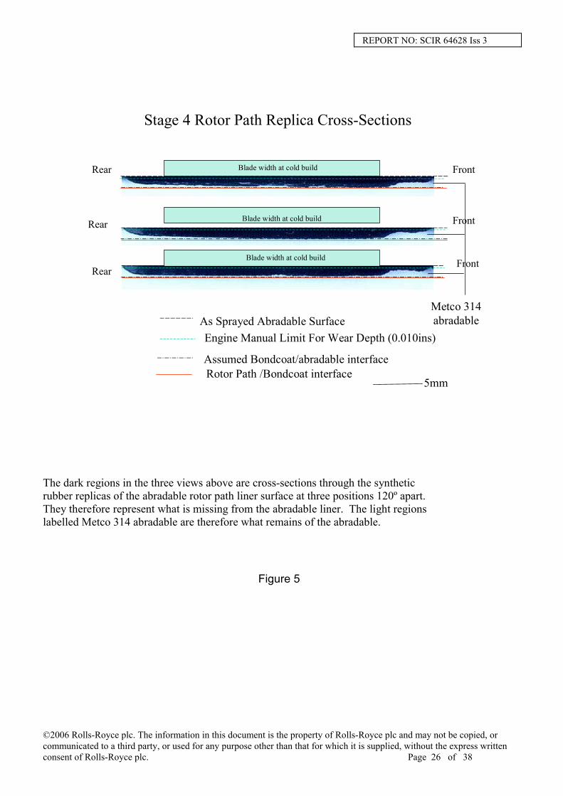
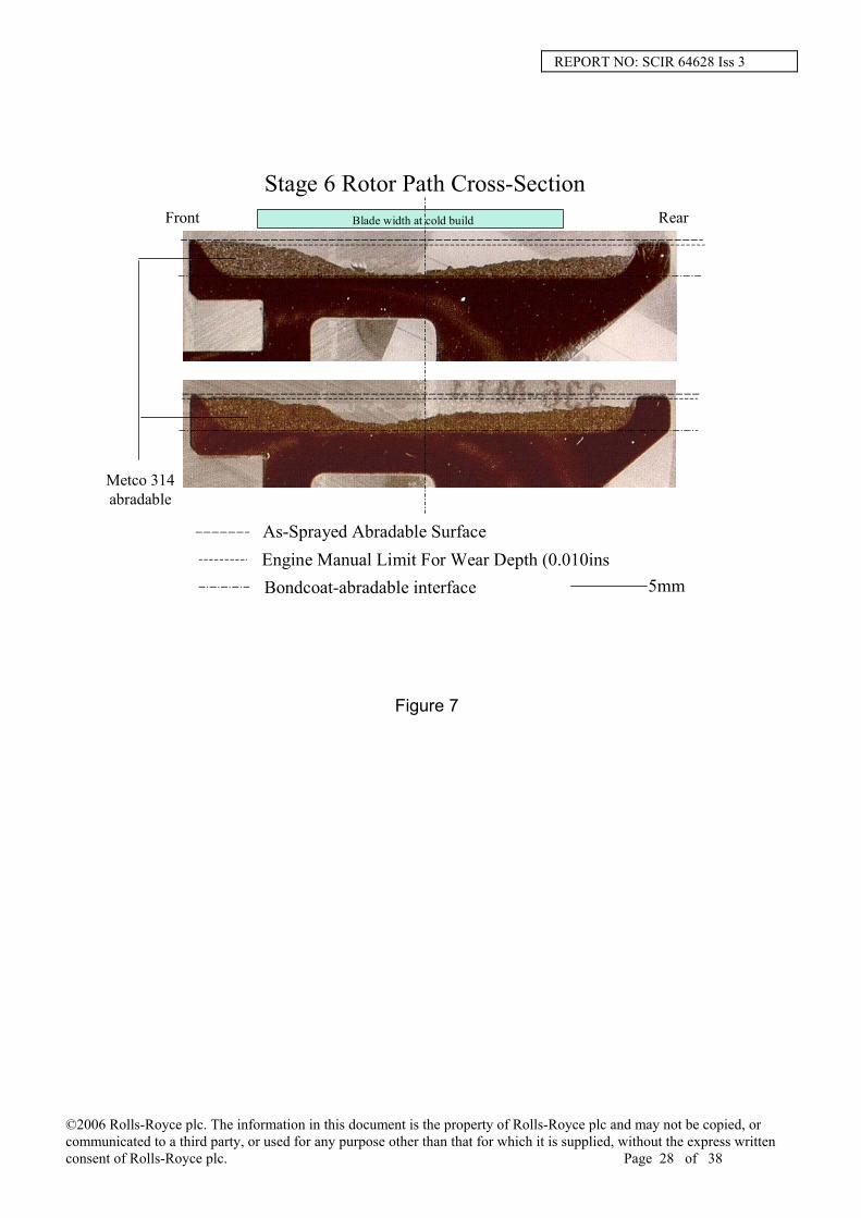
5.1.2 EVALUATION (REPLICATION) OF ABRADABLE LOSS AND WEAR PROFILE Synthetic rubber replication medium was used to obtain casts of the abradable rotor path liner from stages 1 and 6 to estimate the volume of material loss and from stages 2, 3, 4 and 5 to measure the wear profile. For the volume loss evaluations the rubber compound was applied over a 90º arc of the abradable, using the edges of the metal casing at the sides of the rotor path as guides for smoothing the liquid rubber to the level assumed for the originally machined abradable surface. The volume of the solid rubber replica was measured using equipment which accurately weighed the replica in air and then when submerged in water. The volume loss of material calculated for stages 1 and 6 are given in the table below. Replicas of the rotor path abradable lining were made at 120º intervals around stages 2-5 and sectioned to show the cross-section. In addition, a depth micrometer was also used to cross-check the depth of abradable loss. The values of abradable thickness loss are given in the table below. Typical cross-sections through stages 2 to 5 are shown in Figures 3 to 7. Superimposed on the cross-sections are the assumed position of the as-sprayed surface, Engine Manual limits for wear (0,25 mm) and the bondcoat / abradable interface position. The width of the blade at cold build is also indicated for stages 3 to 6 but the rubbed track on the abradable will be wider than this. The depth of wear on all of the stages exceeds Engine Manual limits and coating has been lost outside the anticipated blade contact area particularly for stages 4, 5 and 6. The replicas show that on stages 4 and 5 almost all of the coating has been lost down to the bondcoat, confirming the measurements made with the depth micrometer.
©2006 Rolls-Royce plc. The information in this document is the property of Rolls-Royce plc and may not be copied, or communicated to a third party, or used for any purpose other than that for which it is supplied, without the express written consent of Rolls-Royce plc. Page 7 of 38

REPORT NO: SCIR 64628 Iss 3 Table showing abradable coating measurements
Stage Design Thickness
(mm) Wear Depth (mm) Abradable Volume Loss
cm3 % of total 1 2,39 1,43 max 78.5 35 2 1,17 0,77 typical ~40* 3 1,17 0,65 typical ~35* 4 1,17 1,07 typical ~80* 5 1,17 1,06 typical ~80* 6 2,39 2,29 max 58.1 35
* calculation based on a combination of the typical thickness of the abradable lost and cross-sections taken through abradable replicas
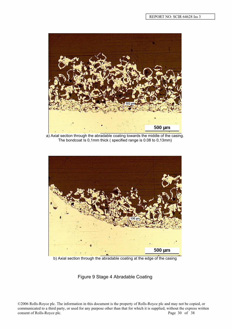
5.1.3 METALLOGRAPHY EXAMINATION Stages 1 and 6 together with Stages 4 and 5 were sectioned to allow the abradable coating to be examined. Stages 2 and 3 were kept intact to allow them to be reworked following this investigation. Initially it was hoped that fragments of coating could be removed from stages 2, 3 and 4 to allow the abradable coating microstructure to be assessed but attempting to chisel off coating from these stages resulted only in fine particles being produced. Stage 1 Figure 8 shows a typical cross-section through the Sherritt Gordon coating and the slightly increased porosity in the corner at the edge of the wear track, which is usual because of the increased turbulence arising in this region when depositing the coating. The general structure of the coating conforms to the Rolls-Royce quality acceptance standard (Ref 9.0), containing acceptable proportions of metallic phase, graphite and porosity. Stage 4 Virtually all of the abradable coating had been removed from this stage with only the Ni-Al bondcoat and isolated fragments of abradable left, Figure 9 (a) and (b). As mentioned above, the coating at the corner position may not be representative of the rest of the coating because of the curvature of the corner leading to turbulence during spraying. Image analysis software calculated that the metallic phase content was 40 % but the limited material available for analysis renders this result unreliable. The guideline figure for the coating, as stated in the Rolls-Royce quality acceptance standard (Ref 9.0), is 40%. The coating contained unmelted particles in the abradable whilst the bondcoat also contained unmelts and internal oxides to a higher degree than usual. The bondcoat thickness was within specification at 0,1mm. A small amount of bondcoat / substrate interface oxidation was present. This oxidation was also present on the rest of the casing surface Stage 5 As with stage 4, the vast majority of the abradable coating was missing with only a small volume of material remaining at the forward edge of the rotor path, Figure 10 (a) and (b). The structure of the coating and the bondcoat was similar to stage 4 and while the metallic phase content was measured at 28.7% the reservations applied to stage 4 as to the reliability of this value apply. An increased amount of bondcoat/substrate interface oxidation compared to stage 4 was present (Figure 10b) together with similar oxidation to the rest of the casing surface. Fingers of oxidation extended into the IN907 (casing) caused by accelerated oxidation at grain boundaries. Beneath the coating, cracks were present normal to the substrate surface within the oxide some of which extended into the bondcoat similar to stage 6 as shown in Figure 11.
©2006 Rolls-Royce plc. The information in this document is the property of Rolls-Royce plc and may not be copied, or communicated to a third party, or used for any purpose other than that for which it is supplied, without the express written consent of Rolls-Royce plc. Page 8 of 38

REPORT NO: SCIR 64628 Iss 3 Stage 6 Again, the abradable coating contained unmelted particles i.e. powder particles whose metallic shell was relatively undisturbed, and image analysis indicated a metallic phase content of 29.1%. The bondcoat thickness was within specification (0,08-0,13mm) but contained a high number of unmelts and porosity. An even greater amount of oxidation was present than seen on stage 5. An increased number of fine cracks within the oxide were present which extended up into the bondcoat compared to Stage 5, Figure 11. As mentioned above the oxidation seen at the bondcoat-substrate interface was present on all of the exposed surfaces of the casings. On these exposed surfaces the depth of oxidation increased progressively from stage 4 (40µm) to stage 5 (110µm) to stage 6 (170µm) similar to the bondcoat-substrate interface oxidation. This implies that the oxidation has increased as the temperature to which the material has been operating increased. If the oxidation arose because of an operation during the refurbishment of the coating it would be reasonable to expect it to be reasonably uniform in depth on all three casings. No surface oxidation was visible on the stage 1 casing which was also manufactured from IN907 which further suggests it occurs because of the temperature experienced in service. Stage 1 will experience ~300C while stage 6 temperature is ~600C. Company B Sprayed Test Samples The quality specification (ref 9.0) requires that a test sample is sprayed at the same time as the casings, this is used to assess the spray quality of each lining, and each sample is hardness checked. The samples for the stage 2 – 6 casing being investigated were supplied by company B for investigation. Cross-sections taken through the test samples were examined. The Metco 314 samples showed a higher metallic phase content (38.5%) with a greater degree of melting such that a more substantial metallic network was formed compared to the rotor path linings, Figure 12. The bondcoat test sample was also different to the rotor path bondcoats with less unmelted particles and less porosity, which was more in line with the specification coating standard. Figure 13. Figure 14 summarises the phase distribution in the Metco 314. The first and second bars show the metallic content / porosity and bentonite ratio for the Rolls-Royce and company B quality standards respectively, the third bar shows the ratio for the test samples provided by company B and the 3rd, 4th and 5th bars show the ratio for the stage 4, 5 and 6 casings examined.
5.1.4 SCANNING ELECTRON MICROSCOPY Chemical analysis of both the abradable and bondcoat materials, using electron microscopy, confirmed that the chemical elements present were consistent with the Metco 314 and the Ni-Al bondcoat respectively. Chemical analysis of the oxidation visible at the bondcoat-IN907 substrate interface (e.g. in Figure 11(b)) found iron oxide i.e. this was a result of oxidation of the IN907 substrate. Clear paths through the remaining abradable and bondcoat were visible, which would allow air easy access to the IN907 substrate, accounting for the oxidation seen. Oxidation at the particle interface boundaries within the bondcoat was predominantly nickel oxide. Smeared material on the surface of stages 3 and 4 was removed. Chemical analysis identified it as rotor blade material (IN718).
5.2 COMPANY B PROCESS INVESTIGATION
As part of the overall investigation, company B provided the information requested by Rolls-Royce (listed in 5.2.1 below) in order to carry out a remote audit of their spraying process. The objective of this exercise was to identify any deficiencies in the process that could have lead to lining quality issue.
©2006 Rolls-Royce plc. The information in this document is the property of Rolls-Royce plc and may not be copied, or communicated to a third party, or used for any purpose other than that for which it is supplied, without the express written consent of Rolls-Royce plc. Page 9 of 38
REPORT NO: SCIR 64628 Iss 3
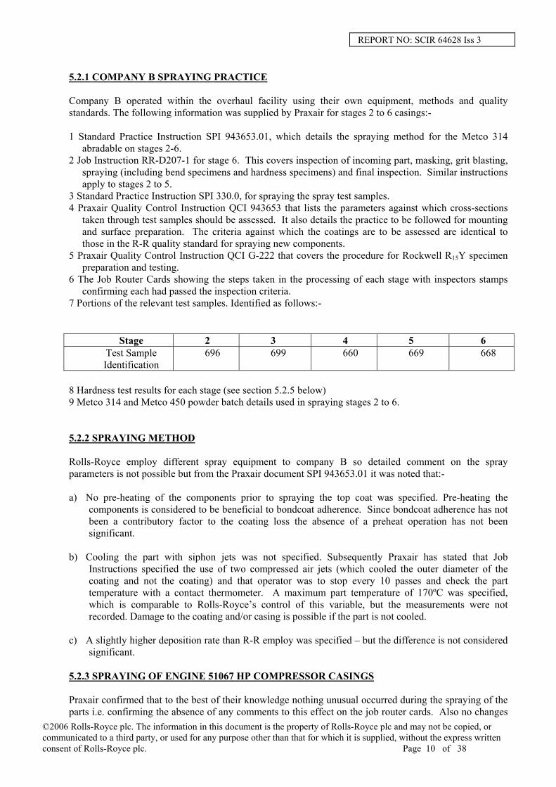
5.2.1 COMPANY B SPRAYING PRACTICE Company B operated within the overhaul facility using their own equipment, methods and quality standards. The following information was supplied by Praxair for stages 2 to 6 casings:- 1 Standard Practice Instruction SPI 943653.01, which details the spraying method for the Metco 314
abradable on stages 2-6. 2 Job Instruction RR-D207-1 for stage 6. This covers inspection of incoming part, masking, grit blasting,
spraying (including bend specimens and hardness specimens) and final inspection. Similar instructions apply to stages 2 to 5.
3 Standard Practice Instruction SPI 330.0, for spraying the spray test samples. 4 Praxair Quality Control Instruction QCI 943653 that lists the parameters against which cross-sections
taken through test samples should be assessed. It also details the practice to be followed for mounting and surface preparation. The criteria against which the coatings are to be assessed are identical to those in the R-R quality standard for spraying new components.
5 Praxair Quality Control Instruction QCI G-222 that covers the procedure for Rockwell R15Y specimen preparation and testing.
6 The Job Router Cards showing the steps taken in the processing of each stage with inspectors stamps confirming each had passed the inspection criteria.
7 Portions of the relevant test samples. Identified as follows:-
Stage 2 3 4 5 6 Test Sample Identification
696 699 660 669 668
8 Hardness test results for each stage (see section 5.2.5 below) 9 Metco 314 and Metco 450 powder batch details used in spraying stages 2 to 6. 5.2.2 SPRAYING METHOD Rolls-Royce employ different spray equipment to company B so detailed comment on the spray parameters is not possible but from the Praxair document SPI 943653.01 it was noted that:- a) No pre-heating of the components prior to spraying the top coat was specified. Pre-heating the
components is considered to be beneficial to bondcoat adherence. Since bondcoat adherence has not been a contributory factor to the coating loss the absence of a preheat operation has not been significant.
b) Cooling the part with siphon jets was not specified. Subsequently Praxair has stated that Job
Instructions specified the use of two compressed air jets (which cooled the outer diameter of the coating and not the coating) and that operator was to stop every 10 passes and check the part temperature with a contact thermometer. A maximum part temperature of 170ºC was specified, which is comparable to Rolls-Royce’s control of this variable, but the measurements were not recorded. Damage to the coating and/or casing is possible if the part is not cooled.
c) A slightly higher deposition rate than R-R employ was specified – but the difference is not considered
significant. 5.2.3 SPRAYING OF ENGINE 51067 HP COMPRESSOR CASINGS Praxair confirmed that to the best of their knowledge nothing unusual occurred during the spraying of the parts i.e. confirming the absence of any comments to this effect on the job router cards. Also no changes
©2006 Rolls-Royce plc. The information in this document is the property of Rolls-Royce plc and may not be copied, or communicated to a third party, or used for any purpose other than that for which it is supplied, without the express written consent of Rolls-Royce plc. Page 10 of 38
REPORT NO: SCIR 64628 Iss 3 to spray equipment, operating personnel, tooling, spray procedures or consumable specification and sourcing had taken place at the relevant times at which the parts were sprayed. 5.2.4 SPRAYING OF TEST AND HARDNESS SAMPLES Praxair stated that the test samples were sprayed in exactly the same manner as the parts. Job Instruction R-R-D207 states the samples should either be mounted with the parts or mounted on the turntable to simulate actual parts. This should ensure similarity of the coating on parts and test pieces and should ensure that no differences arise because of spraying in a different pattern for example. The method for preparing the surface prior to hardness testing can influence the result obtained. The practice specified by Praxair in QCI G-222 was in line with that used by R-R i.e. abrade the surface with 120 to 220 grit silicon carbide paper to produce a surface uniform in appearance.
5.2.5 HARDNESS TESTING Hardness testing of the abradables on any of the stages was not possible because of insufficient material. The Sherritt Gordon stage 1 as-sprayed hardness recorded by R-R Hillington was 48 R15Y i.e. within the R-R quality standard guidelines of 30-50 R15Y. The R15Y hardness values measured by company B on the Metco 314 test samples they sprayed for stages 2 to 6 were within the required range:-
Stage 2 Stage 3 Stage 4 Stage 5 Stage 6 R-R and
company B Quality Limits
51.8
51.7
48.8
48.6
49.4
45-55
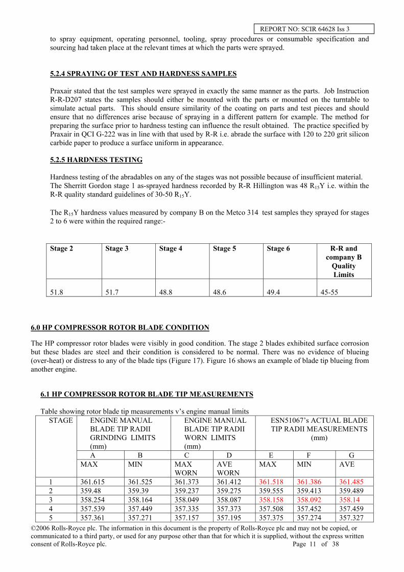
6.0 HP COMPRESSOR ROTOR BLADE CONDITION The HP compressor rotor blades were visibly in good condition. The stage 2 blades exhibited surface corrosion but these blades are steel and their condition is considered to be normal. There was no evidence of blueing (over-heat) or distress to any of the blade tips (Figure 17). Figure 16 shows an example of blade tip blueing from another engine.
6.1 HP COMPRESSOR ROTOR BLADE TIP MEASUREMENTS
Table showing rotor blade tip measurements v’s engine manual limits ENGINE MANUAL BLADE TIP RADII GRINDING LIMITS (mm)
ENGINE MANUAL BLADE TIP RADII WORN LIMITS (mm)
ESN51067’s ACTUAL BLADE TIP RADII MEASUREMENTS
(mm)
A B C D E F G
STAGE
MAX MIN MAX WORN
AVE WORN
MAX MIN AVE
1 361.615 361.525 361.373 361.412 361.518 361.386 361.485 2 359.48 359.39 359.237 359.275 359.555 359.413 359.489 3 358.254 358.164 358.049 358.087 358.158 358.092 358.14 4 357.539 357.449 357.335 357.373 357.508 357.452 357.459 5 357.361 357.271 357.157 357.195 357.375 357.274 357.327
©2006 Rolls-Royce plc. The information in this document is the property of Rolls-Royce plc and may not be copied, or communicated to a third party, or used for any purpose other than that for which it is supplied, without the express written consent of Rolls-Royce plc. Page 11 of 38

REPORT NO: SCIR 64628 Iss 3 6 356.869 356.959 356.756 356.794 357.017 356.895 356.956
Columns A and B under the ENGINE MANUAL BLADE TIP RADII GRINDING LIMITS heading are the dimensions used for HP compressor rotors at new engine build and for full performance restoration engines at overhaul. Columns C and D under the ENGINE MANUAL BLADE TIP RADII WORN LIMITS heading are the maximum worn and average limits for check and repair engines at overhaul. Columns E, F and G under the ACTUAL BLADE TIP RADII heading are the maximum, minimum and average actual blade tip radius dimensions for the HP compressor from 51067. The dimensions shown in red are below the minimum grinding limit stated in column B, although they are within the max and average worn dimensions shown in column C and D. See Table in section 9.1 for comparison of the above HP compressor rotor blade tip measurements with those from other engines
7.0 DIGITAL FLIGHT DATA RECORDER (DFDR) ANALYSIS
Fig 15 shows the DFDR take-off data for the event on 25 August 2004, the following data are plotted: LP shaft speed N1 (%) HP shaft speed N3 (%) Throttle angle (degrees) TGT (degrees) P30 (psi) The data shows that the engine surges approx 33 seconds after applying max take-off power. This is a known pinch point, where HP compressor blade tip clearances are at their largest. This is due to faster thermal growth of the HP compressor casings relative to the thermal growth of the discs in the HP rotor, due to the mass differential . The surge is identified by the pressure drop and TGT rise. There is also an uncommanded rise in N3 speed, which suggests a HP compressor stall. The throttle angle is reduced 60 seconds after the initial surge and the engine recovers from the surge and is operating normally, but at a reduced power. The engine is shut down approximately 20 seconds after the engine recovered. On the basis that the engine was stable following the power reduction, the engine potentially need not have been shut-down. The data also shows there was no increase in N1 speed prior to the core surge, indicative of a fan stall. This suggests that the core fairing release was secondary. It is considered that if the fairing release had been primary it would only have affected the fan working line and lead to a fan stall. The fairing release would not have caused the large tip clearances to then cause the core surge. As a significant amount of fairing material was found on the runway, it is more likely that the fairing released during the initial surge event at rotation.
8.0 LH UPPER FAIRING RELEASE The left hand upper composite fairing was found to have released from it’s fixing points (figure 18 and 19) when the ‘C’ ducts were opened up to carry out a visual inspection of the VSV stage 1 and 2 levers was requested during on-ground inspection checks. All bolts remained in position but no torque values are available. The ATSB are carrying out their own investigation on the fairing release, which will be reported separately.
©2006 Rolls-Royce plc. The information in this document is the property of Rolls-Royce plc and may not be copied, or communicated to a third party, or used for any purpose other than that for which it is supplied, without the express written consent of Rolls-Royce plc. Page 12 of 38

REPORT NO: SCIR 64628 Iss 3 9.0 DISCUSSION
9.1 HP ROTOR BLADES. Table showing Trent 800 HP compressor blade tip measurements as measured at overhaul
REASON FOR REMOVAL
STAGE 1
STAGE 2
STAGE 3
STAGE 4
STAGE 5
STAGE 6
LINING MATERIAL
SHERRITT GORDON
METCO 314
METCO 314
METCO 314
METCO 314
METCO 314
EM MIN 361.525 359.39 358.164 357.449 357.271 356.869 51067 ENGINE SURGE /
DETERIORATION 361.386 359.413 358.092 357.452 357.274 356.895
51135 ENGINE SURGE ON TEST
361.526 359.481 358.216 357.401 357.33 356.578
51172 ENGINE SURGE / ICE INGESTION 361.554 359.090 357.904 357.485 357.256 356.822
51017 ENGINE SURGE/ HPC STAGE 6 BLADE DAMAGE 361.424 358.940 357.657 356.753 356.418 356.057
51021 HPC STAGE 5-6 DRUM LIFE 361.551 359.372 357.894 356.890 356.761 356.296
51046 IPC DAMAGE 361.526 359.395 357.871 357.467 357.243 356.466 51148 DETERIORATION 361.414 359.308 357.530 356.852 357.106 356.182 51105 HIGH LIFE 361.62 359.477 358.128 357.542 357.057 356.787 51238 ENGINE SURGE /
DETERIORATION 361.526 359.024 357.901 357.038 356.789 356.428 * Measurements below engine manual grinding limits are shown in red.
The HP compressor rotor blade tip measurements for 51067 are considered to be unusual. The HP compressor rotor blade tip measurements for a number of Trent 800 engines, in the table above, supports this statement. It can be seen that the blade tip measurements for 51067, with the exception of stage 1 blades, which runs in Sherritt Gordon lining material, only stage 3 blades are only marginally undersize. In comparison, most of the blades running in Metco 314 for the other engines are undersize. In addition to rotor blade tip wear, under certain conditions, it is possible to cause blueing (over-heating due to heavy rubbing) and distress to the blade tips. An example is shown in figure 16. There was no such blueing or distress to the blades from 51067 (figure 17).
9.2 HP COMPRESSOR ROTOR BLADE TIP CLEARANCES
Table showing HP compressor rotor blade tip clearances ESN REASON FOR
REMOVAL STAGE
1 STAGE
2 STAGE
3 STAGE
4 STAGE
5 STAGE
6 COLD BUILD CLEARANCE
1.32 1.02 0.99 1.02 1.19 1.37
51067 ENGINE SURGE/ DETERIORATION *3.21 2.02 1.95 2.33 2.48 *3.86
51238 ENGINE SURGE/ DETERIORATION
2.54
1.96
1.88
2.00
2.13
2.24
51105 HIGH LIFE 1.75 1.45 1.25 1.42 1.91 1.63 * Patchy lining loss
Engine 51238 surged at high power due to large HP compressor rotor blade tip clearances. Analysis of the data showed that the tip clearance effect on surge margin to be approx 10 % greater than that expected for an
©2006 Rolls-Royce plc. The information in this document is the property of Rolls-Royce plc and may not be copied, or communicated to a third party, or used for any purpose other than that for which it is supplied, without the express written consent of Rolls-Royce plc. Page 13 of 38

REPORT NO: SCIR 64628 Iss 3 engine removed from service due to performance deterioration. It can seen that engine 51067’s tip clearances are larger than those measured and analysed for 51238 (albeit the lining loss on stage 1 and 6 was patchy). It is therefore possible to conclude that the engine surged at high power due to the large tip clearances at the rear stages of the HP compressor. 9.3 ROTOR PATH LININGS The stage 1 casing lining microstructure was satisfactory, however lining loss was experienced. Service experience with Sherritt Gordon indicates that a number of engines typically lose some areas of lining, the extent on 51067 is greater than normal. Sherritt Gordon can suffer from age softening and thermal fatigue, leading to lining loss. Loss of front stage linings on Trent 800 engine causes poor starting and does not cause high power surges. There is no evidence of abradable coating delamination in the Metco 314 linings. This type of failure mechanism leads to wholesale abradable coating loss in large sections. This is characterised by cracking running from the edge of the casing at the abradable / bondcoat interface. It is considered that these linings eroded over a period of time until they were large enough to cause the engine to surge. At the point of surge the casings deflected heavily causing the smearing evident on the linings. Note the smearing i.e. the transfer of blade tip material to the lining material can only be light due to the light wear to the blades. The lining has been lost progressively by an erosion mechanism caused by the low metallic phase and high proportion of bentonite and porosity. This is supported by the fact that no wear has taken place to the HPC rotor blade tips. Normally Metco 314 is abradable initially but quickly becomes abrasive due to the lining hardening. Rubs depths of 0,25 mm are considered normal. Metco 314 lining are used in the rear stages of all RB211 and Trent engines service experience has been excellent with lining loss events being very rare. The HP compressor efficiency analysis, carried out post the event, shows it begins a downward trend around 250 cycles after returning to service following refurbishment and continued to deteriorate until the surge event 360 cycles later. This is consistent with progressive lining loss increasing the tip clearance in the HP compressor, reducing the efficiency. The IP compressor efficiency remained unaffected. 9.4 SPRAY PROCESS INVESTIGATION The reasons for the casings being sprayed with an abradable below the normal standard and this escaping detection by the supplier are unclear. While there were no aspects of the spraying procedure and parameters which were obviously at fault there was evidence of a lack of the required degree of melting and particle cohesion in both the abradable and the bondcoat indicating that the spray parameters have not been within ideal limits. The quality control samples indicated that the coatings would be to the quality desired but there was variation between the test samples and components in both the abradable and the bondcoat, suggesting that they had not been sprayed in the same manner. company B relined HP compressor casings in the period October 2002 to March 2004. These casings are fitted to 53 engines across the Trent 800 fleet and 1 Trent 700 engine. Since the 51067 event, two other engines have been identified as having exceeded the TGT deterioration limit through engine health monitoring alerts, subsequently found to partly or wholly due to HP compressor lining loss. ESN 51058 was found to have lost HP compressor stage 6 linings on engine strip. Rolls-Royce is currently carrying out an investigation on this casing, which had been relined by company B. ESN 51076 was actually removed for HP compressor blade damage but was also found to have lining loss on engine strip. Again, the casings had been relined by company B.
The overhaul facility terminated business with company B in March of this year. Since March, HPC casings have been resprayed by alternative sub-contractors.
©2006 Rolls-Royce plc. The information in this document is the property of Rolls-Royce plc and may not be copied, or communicated to a third party, or used for any purpose other than that for which it is supplied, without the express written consent of Rolls-Royce plc. Page 14 of 38

REPORT NO: SCIR 64628 Iss 3
9.5 SERVICE MANAGEMENT The engine health monitoring (EHM) monitoring carried out by DS&S monitors both absolute and step changes in TGT. If either TGT limit is exceeded, an alert will be issued. An EHM alert was issued on 4 August 2004 for 51067 due to a step change in TGT margin being noted. Troubleshooting was carried out on the engine in accordance with the fault isolation manual (FIM), reference chapter 71-05, task 828. A borescope inspection of the HP compressor was carried out as part of the troubleshooting and minor damage (within AMM acceptance limits) to a small number of HPC stage 6 blades was reported The engine was allowed to continue in service. Since this event, EHM procedures have been changed. If an EHM alert is issued and troubleshooting reveals no findings to explain the observed trend change, Rolls-Royce will review engine parameter data in more detail. This may lead to a recommendation that the engine is removed, particularly where the HP casings have been resprayed by company B. The Boeing AMM will be updated to include an inspection check of the condition of the rotor path lining immediately adjacent to the borescope port hole and to contact Rolls-Royce if no evidence of lining loss (ref request for manual revision document number 5008).
Rolls-Royce has also developed an algorithm to alert changes of HP compressor efficiency as part of the suite of automatically generated alerts produced by DS&S for EHM purposes.
10.0 REFERENCES
CME 5033/2/E1 – Engineering Coating Standards for Thermal Spray Coatings - Generic 11.0 GLOSSARY OF TERMS
AMM - Aircraft maintenance manual ATSB - Australian Transport Safety Bureau DS&S - Data Systems and Solutions EHM - Engine health monitoring FIM - Fault isolation manual HAESL - Hong Kong Aero Engines Services HP - High Pressure IP - Intermediate Pressure LH - Left Hand QC - Quality Control TGT - Turbine gas temperature
T30 - HP Compressor Outlet Temperature
©2006 Rolls-Royce plc. The information in this document is the property of Rolls-Royce plc and may not be copied, or communicated to a third party, or used for any purpose other than that for which it is supplied, without the express written consent of Rolls-Royce plc. Page 15 of 38

REPORT NO: SCIR 64628 Iss 3 12.0 ADDENDUM
12.1 COMPANY C’S INVESTIGATIONS
12.1.1 ESN51067 – SECTION OF HP COMPRESSOR STAGE 6 CASING A section of stage 6 casing from 51067 was requested by company C to support their investigation. About this time company C realised that the QC samples submitted to Rolls-Royce for the 51067 casings were not the correct samples. Eventually the correct samples were identified and examined by company C. The investigation concluded that the micro structure of QC sample No.466 for the 51067 HP compressor stage 6 had a metallic content of 40.5% which is similar to the Rolls-Royce quality standard recommendation of 40%. The measured hardness of 51.7 was also within the Rolls-Royce quality recommendation of 45-55 R15Y. Examination of the section of stage 6 casing confirmed a low metallic content of 27%.
12.1.2 ESN51363 – HP COMPRESSOR STAGE 6 CASING The Data Systems and Support Group identified an increasing TGT trend on ESN51363 and a loss of HP compressor efficiency relative to the ‘sister ‘ engine. Following confirmation that the stage 6 casing had been relined by company B a decision was taken to remove the engine. Strip of the HP compressor revealed patchy lining loss from the HP compressor stage 6 casing similar to that seen on 51067 and 51058’s stage 6 casings. The stage 5 casing, which had not been relined by company B, did not exhibit lining loss. Rolls-Royce were supplied with photographs (fig 20 and 21) and the lining hardness values of the stage 5 and 6 casings but declined to have them returned for investigation. Company C did however conduct an extensive investigation into the stage 6 lining failure examining micro structures and phase distribution, chemical analysis of the bulk coating and contaminants, oxidation, coefficient of thermal expansion, erosion resistance and CMAS contamination. Company C’s examination of the microstructure concluded direct comparison of the QC sample (No.864) and the casing. The metallic content of this QC sample was found to be 40.9% and the sample removed from the casing was found to be 43.1%, both samples were therefore acceptable against the Rolls-Royce quality standard recommendations of 40%.
12.1.3 FOLLOW-UP INVESTIGATION BY ROLLS-ROYCE On completion of their own investigation, company C sent the correct quality control samples from 51067 and the QC samples and fragments of the coating from the stage 6 casing from ESN51363 to Rolls-Royce.
12.1.3.1 EXAMINATION OF CORRECT QUALITY CONTROL SAMPLES FROM 51067 Examination of the correct set of QC samples from 51067 revealed similarity with the first incorrect set of QC samples, in terms of metallic content and reacted particles. This goes no further towards highlighting any inadequacies with the company B manufacturing process.
12.1.3.2 PHASE DISTRIBUTION OF STAGE 6 COATING MICRO STRUCTURE FROM 51363
©2006 Rolls-Royce plc. The information in this document is the property of Rolls-Royce plc and may not be copied, or communicated to a third party, or used for any purpose other than that for which it is supplied, without the express written consent of Rolls-Royce plc. Page 16 of 38

REPORT NO: SCIR 64628 Iss 3 Image analysis was used to determine the phase distribution of the QC samples and fragments of coating chipped from 51363 stage 6 coating. The results from the investigation indicated the metallic content in both the QC sample and the chipped coatings from the stage 6 casing were similar to the Rolls-Royce quality standard.
12.1.4 FOLLOW-UP INVESTIGATION DISCUSSION Rolls-Royce concluded that the coating in the HP compressor stage 6 casing from ESN51067 had a low metallic content and, consequently, a higher proportion of bentonite and porosity compared to the Rolls-Royce acceptance standard. Also, there were a high number of particles, which had not been fully melted. This caused the coating to be more friable than normal, leading to the erosion during service operation. Following their own investigation, company C concluded that the QC sample was the same as the coating in the casing as it left the company B coating cell in August 2003. The company C report does not offer a reason for the high number of unmelted particles but concludes that the low metallic content was due to the loss of particles from deep within the coating structure during operation. Company C also concluded that the erosion was not caused by low metallic content in the coating, but rather by severe oxidation of the coating as a consequence of engine operating conditions. Company C suggested that the operation may have been above the recommended operating temperature for the lining and hence could have caused the excessive oxidation of both the coating and substrate. Rolls-Royce does not accept Praxair’s conclusions for the cause of lining loss. The take-off performance data for 51067 for the last 400 cycles prior to the event shows that the engine had been operating normally. As stated previously, DS&S issued an alert on 04 August 2004 following a step change in TGT, the engine still had 10 °C margin just before it surged. The maximum temperature capability of Metco 314 is around 815 °C, so the suggestion that the engine may have been above the recommended operating temperature for the lining can be ruled out. Rolls-Royce has carried out an investigation to assess the degree of abradable coating oxidation on HP compressor stage 5 and 6 casings from 51058. The stage 5 casing, which had not been relined by company B, did not exhibit lining loss (see fig 22). The stage 6 casing, which had been relined by company B, did exhibit lining loss (see fig 23). Electron microscope images were taken from micro samples prepared from the sectioned casings and the percent oxidation measured using image analysis software. The results from the investigation showed the oxidation content on stage 5 casing to be 20.6% compared to 10.4% for the eroded stage 6 casing. This suggests oxidation was not the primary driver for erosion. Hardness measurements have been taken from the engine stage 5 and 6 casings from 51058 and 51363, post engine running (see table below). Again, the stage 5 casing from 51363 had not been relined by company B but the stage 6 casing had. The hardness requirement for ‘as sprayed’ Metco 314 is 45 to 55 R15Y. Metco 314 hardens during engine running, therefore, the hardness values for engine run components should be greater than the ‘as sprayed’ hardness values. It can be seen from the table that the coating hardness measurements for stage 5 casings are harder than for the stage 6 casings. This is particularly evident on the casings from 51058, further supporting a problem with the company B sprayed linings. No attempt was made to determine the hardness of the linings in any of the HP compressor casings from 51067 due to the amount of lining loss. However, wear normally occurs to the HP compressor blade tips due to the ‘hard’ Metco 314 lining. The table in 6.1 shows the HP compressor blade tip measurements from 51067 as measured post the event. This reveals that all stages of blades rubbing against Metco 314, with the exception of the stage 3, are still within engine manual grinding limits after 2256 hours and 614 cycles of engine running. This is unusual and is considered to be a result of the blades rubbing against a
©2006 Rolls-Royce plc. The information in this document is the property of Rolls-Royce plc and may not be copied, or communicated to a third party, or used for any purpose other than that for which it is supplied, without the express written consent of Rolls-Royce plc. Page 17 of 38

REPORT NO: SCIR 64628 Iss 3 ‘soft’ lining. This is supported by more typical blade wear, as shown in the table in 9.1, for other Trent 800 engines.
Table showing the hardness values obtained for the linings from engine run casings
ESN Casing Stage
Sprayed by company B
Hardness value (R15Y)
Source
51363 5 No 62.1 Company A
6 Yes 51 Company C
51058 5 No 80 Rolls-Royce
6 Yes 35 Rolls-Royce
The differences between the quality QC sample and the coating in the stage 6 casing from ESN51067 cannot be explained. Also, no explanation can be given for the apparent acceptable quality of the QC sample and the stage 6 casing from ESN51363. However, the most compelling evidence for contesting Praxair’s conclusions is the Metco 314 service history in Trent 800 engines. Praxair suggested the thermal expansion coefficient mismatch between the coating and the substrate may have initiated the coating loss. The Trent 800 entered into service in 1995. There are now 450+ Trent 800 engines in service, which have accrued more than 7 million hours of service operation. In this time, only five engines have been removed from service for loss of TGT margin and HP compressor efficiency, which subsequently was found to be due to Metco 314 lining loss. In each case, the casing that had lost Metco 314 lining had been relining by company B at the previous shop visit. Prior to the ESN51067 event date, Rolls-Royce has no history of Metco 314 lining loss, either as sprayed from new manufacture or resprayed at overhaul. Further, company B had set up their spraying facility within company A. Following termination of the company A / company B contract in March 2004, company A purchased the cell equipment ‘as is’ from them later that year. The company B spraying process and ‘areas for improvement’ are stated in 5.2.1 and 5.2.2 respectively. company A made the following changes to equipment / process to improve the quality of component spraying:
• Introduced automated grit blasting process to ensure consistent preparation of the surface. • Introduced additional cooling air to cool the component during spraying • Plasma gun changed from a FP73 type to a 9MB type, as specified in the engine manual. • Introduced new tooling and fixtures to hold the components properly during spraying no ensure
no heat distortion • Measure the flame spray hardness on the actual component • Improved house-keeping
o Distilled water now changed every quarter o Grit blast media now changed every two weeks o Powder hoppers moved from outside to inside the spray booth
For the reasons stated above, Rolls-Royce reject the conclusions made by Company C as to the cause of the lining loss
©2006 Rolls-Royce plc. The information in this document is the property of Rolls-Royce plc and may not be copied, or communicated to a third party, or used for any purpose other than that for which it is supplied, without the express written consent of Rolls-Royce plc. Page 18 of 38

REPORT NO: SCIR 64628 Iss 3
13.0 ADDENDUM 2
13.1 Company C’S Addendum to Technical Note 05-14 Following issue 2 of this report Company C have added an addendum to Company C Technical Note 05-14, this addendum states the following: “Despite the evidence for erosion in service, the specification for the acceptable quality of the coating contains no evaluation for erosion’ and the current R-R specification for the LCA-314 coatings is not adequate to insure the desired erosion resistance that the coating may experience in some service exposures. Company C suggested a particle erosion test or a tensile bond test should be considered. The bond test would give the average adhesion strength between particles within the coating. This 3-way analysis of the quality panels would thus verify acceptable hardness and metal content and particle adhesion strength of the coating.” 13.2 Rolls-Royce response to Company C statement in 13.1 Rolls-Royce strongly rejects the assertion that the Rolls-Royce specification is inadequate in protecting against erosion and contends that company C have drawn an erroneous conclusion from the available service data. The evidence for this is presented below. 13.3 Rolls-Royce controlling documentation The RR documentation controlling the repair to the HPC casing at the time they were sprayed was TSD594 OP704. This document states the quality control sample must be attached to the part (see extract below); “Where the indentation test cannot be effected on the part an 'integral' test piece must be used, i.e. a test piece which is attached to the part and sprayed with the part. The test piece should be of steel, measuring approximately 6,35 x 20,32 x 50,8 mm. (0.250 x 0.800 x 2.000in.)” It is normal for subcontract companies to put in place internal local working procedures that comply with the Original Engine Manufacture’s (OEM) repair documentation. When originally questioned on the procedure used by company B to generate and measure the hardness of the quality control samples Praxair submitted (28th Oct 04) Job Instruction R-R-D207-1, for HP Compressor Stage 6 Case. on generation of the hardness quality control sample; “R-R-D207-1 Operation N°40 – flame Coat Procedure 9. Mount Macro Hardness Test Coupon together with the parts if possible or mount the coupon on Turntable to simulate actual parts. Procedure 10. Spray top coat (Metco 314 NS) on the test coupon and the actual (For test coupon mounted together with the parts) as per SPI N° 943653.01 to achieve dimension as per Table 3A. Remove the test coupon when the coating thickness is more than 0.050” Procedure 11. For coupon on simulated parts, spray the coupon to 0.050” min; follow by spraying the actual part to size as shown in Table 3A.”
©2006 Rolls-Royce plc. The information in this document is the property of Rolls-Royce plc and may not be copied, or communicated to a third party, or used for any purpose other than that for which it is supplied, without the express written consent of Rolls-Royce plc. Page 19 of 38
This procedure allows the test sample to be mounted and sprayed separately to the actual casing ring. This process therefore does not comply with the stated Rolls-Royce repair scheme.

REPORT NO: SCIR 64628 Iss 3 In addition to this information a fax from Fred Mundt (6th Oct 04) confirmed the component was sprayed to the Praxair Standard Practice Instruction 330.00 with the following comments; “The parts and samples were coated at separate times (of necessity) but each representative sample set coated immediately before / after the part in the same coating centre set-up, using the same equipment and material.” The separate spraying of the test piece is considered by Rolls-Royce to be significant. When the test piece is sprayed independently of the casing, it is possible for the quality control sample to have a different hardness value to the actual casing. Rolls-Royce has previous evidence of this (see section 13.5). The Rolls-Royce development and service evidence demonstrates that provided the hardness value of the casing matches the hardness value of the test coupon and both are within the required hardness specification, then the lining will not erode during the planned time between overhauls. Therefore, when all repair documentation requirements are complied with, there is no deficiency in the Rolls-Royce specification. 13.4 Service Evidence of Lining Issues Metco 314 is used in all Trent HP compressor casings and has an excellent ‘in service’ record. In the 10 years of operation, the Trent 800 engine has accrued over 8.8 million hours of service. With the exception of Metco 314 erosion found in casings sprayed by company B, Rolls-Royce experience is that there has not been a single occurrence of Metco 314 lining loss through erosion. This is true for HP compressor casings as sprayed during new manufacture or by vendors other than company B at overhaul. It is also true for all operators despite them operating their engines at different engine ratings and in different environments. 13.5 Previous Experience of Quality Control Test Samples There is known experience of variation between spraying components and quality control samples resulting in the component being out of the required hardness range. RB211-535E4B engines suffered from engine surges and consequently unscheduled engine removals around March 2002. Boroscope inspection of these engines highlighted partial loss of the Metco 320 HPC stage 3 rotor path lining. All affected parts had been reworked in one particular overhaul base, with the introduction of Metco 320. An investigation was launched to determine the root cause of the failure. The findings from the investigation highlighted the following point; Metco 320 test coupons hardness coating structure and component coating structure (and therefore hardness value) could differ if the quality control sample was not sprayed with the component. 13.6 Why have the repair documents been amended since company C casings were sprayed? As part of Repair and Surface Engineering Process Excellence activities launched to support the robust repair of Al/Si based abradable coatings, it was deemed best practice to incorporate the additional quality requirements stipulated in the new manufacture standard (CME 5033 2 / E1) to the repair standard (TSD 594). This “best practice “activity was read-across to all abradable coatings regardless of the service experience. In order to do this document and procedure amendments were required. These changes were made as part of on-going process improvement and not because of any deficiency in the original procedures / documents, relating to spraying Metco 314 to repair HPC casings.
©2006 Rolls-Royce plc. The information in this document is the property of Rolls-Royce plc and may not be copied, or communicated to a third party, or used for any purpose other than that for which it is supplied, without the express written consent of Rolls-Royce plc. Page 20 of 38

REPORT NO: SCIR 64628 Iss 3 13.7 Addendum 2 - Conclusions Based on the above evidence Rolls-Royce strongly reject the assertion that the Rolls-Royce specification is inadequate in protecting against erosion and contend that company C have drawn an erroneous conclusion from the available service data Rolls-Royce conclude that where erosion has occurred, there has been a variation between the spraying of components and the quality control samples; resulting in the component and the test sample or just the component, being below the required hardness range. Additional Statement Nothing in this report shall be deemed to be an admission by Rolls-Royce plc of any liability whatsoever, however arising in respect of any loss, damage, death or injury.
©2006 Rolls-Royce plc. The information in this document is the property of Rolls-Royce plc and may not be copied, or communicated to a third party, or used for any purpose other than that for which it is supplied, without the express written consent of Rolls-Royce plc. Page 21 of 38

REPORT NO: SCIR 64628 Iss 3
©2006 Rolls-Royce plc. The information in this document is the property of Rolls-Royce plc and may not be copied, or communicated to a third party, or used for any purpose other than that for which it is supplied, without the express written consent of Rolls-Royce plc. Page 22 of 38
Figure 1 General view of the HPC casings

REPORT NO: SCIR 64628 Iss 3
©2006 Rolls-Royce plc. The information in this document is the property of Rolls-Royce plc and may not be copied, or communicated to a third party, or used for any purpose other than that for which it is supplied, without the express written consent of Rolls-Royce plc. Page 23 of 38
Smearing on the Stage 1 abradable surface
Stage 3 smearing
Stage 4 smearing
Stage 5 smearing
Figure 2 Examples of the smearing on stages 1, 3, 4 and 5

REPORT NO: SCIR 64628 Iss 3
Stage 2 Rotor Path Replica Cross-Sections
5mmRotor Path /Bondcoat interface
Engine Manual Limit For Wear Depth (0.010ins)
Metco 314 abradable
As Sprayed Abradable Surface
Assumed Bondcoat/abradable interface
The dark regions in the three views above are cross-sections through the synthetic rubber replicas of the abradable rotor path liner surface at three positions 120º apart. They therefore represent what is missing from the abradable liner. The light regions labelled Metco 314 abradable are therefore what remains of the abradable
Figure 3
©2006 Rolls-Royce plc. The information in this document is the property of Rolls-Royce plc and may not be copied, or communicated to a third party, or used for any purpose other than that for which it is supplied, without the express written consent of Rolls-Royce plc. Page 24 of 38

REPORT NO: SCIR 64628 Iss 3
Stage 3 Rotor Path Replica Cross-Sections
As Sprayed Abradable Surface
Engine Manual Limit For Wear Depth (0.010ins)
Rotor Path /Bondcoat interfaceAssumed Bondcoat/abradable interface
Metco 314 abradable
5mm
Front
Front
Front
Rear
Rear
Rear
Blade width at cold build
The dark regions in the three views above are cross-sections through the synthetic rubber replicas of the abradable rotor path liner surface at three positions 120º apart. They therefore represent what is missing from the abradable liner. The light regions labelled Metco 314 abradable are therefore what remains of the abradable.
Figure 4
©2006 Rolls-Royce plc. The information in this document is the property of Rolls-Royce plc and may not be copied, or communicated to a third party, or used for any purpose other than that for which it is supplied, without the express written consent of Rolls-Royce plc. Page 25 of 38
REPORT NO: SCIR 64628 Iss 3
Stage 4 Rotor Path Replica Cross-Sections
As Sprayed Abradable Surface Engine Manual Limit For Wear Depth (0.010ins)
Rotor Path /Bondcoat interface5mm
Assumed Bondcoat/abradable interface
Metco 314 abradable
Front
Front
Front
Rear
Rear
Rear
Blade width at cold build
Blade width at cold build
Blade width at cold build
The dark regions in the three views above are cross-sections through the synthetic rubber replicas of the abradable rotor path liner surface at three positions 120º apart. They therefore represent what is missing from the abradable liner. The light regions labelled Metco 314 abradable are therefore what remains of the abradable.
Figure 5
©2006 Rolls-Royce plc. The information in this document is the property of Rolls-Royce plc and may not be copied, or communicated to a third party, or used for any purpose other than that for which it is supplied, without the express written consent of Rolls-Royce plc. Page 26 of 38

REPORT NO: SCIR 64628 Iss 3
Stage 5 Rotor Path –Typical Cross-Section
5mm
As-Sprayed Abradable Surface
Engine Manual Limit For Wear Depth (0.010ins)
Metco 314
abradable
Bondcoat-abradable interface
Blade width at cold build
Front Rear
Figure 6
©2006 Rolls-Royce plc. The information in this document is the property of Rolls-Royce plc and may not be copied, or communicated to a third party, or used for any purpose other than that for which it is supplied, without the express written consent of Rolls-Royce plc. Page 27 of 38
REPORT NO: SCIR 64628 Iss 3
Stage 6 Rotor Path Cross-Section
5mm
As-Sprayed Abradable SurfaceEngine Manual Limit For Wear Depth (0.010ins
Metco 314 abradable
Bondcoat-abradable interface
Front RearBlade width at cold build
Figure 7
©2006 Rolls-Royce plc. The information in this document is the property of Rolls-Royce plc and may not be copied, or communicated to a third party, or used for any purpose other than that for which it is supplied, without the express written consent of Rolls-Royce plc. Page 28 of 38

REPORT NO: SCIR 64628 Iss 3
a)– Axial cross-section - typical microstructure
b) The Sherrit Gordon Coating in the curved corner at the edge of the casing
Figure 8 Stage 1 Sherritt Gordon Coating
©2006 Rolls-Royce plc. The information in this document is the property of Rolls-Royce plc and may not be copied, or communicated to a third party, or used for any purpose other than that for which it is supplied, without the express written consent of Rolls-Royce plc. Page 29 of 38
REPORT NO: SCIR 64628 Iss 3
a) Axial section through the abradable coating towards the middle of the casing.
The bondcoat Is 0,1mm thick ( specified range is 0.08 to 0,13mm)
b) Axial section through the abradable coating at the edge of the casing
Figure 9 Stage 4 Abradable Coating
©2006 Rolls-Royce plc. The information in this document is the property of Rolls-Royce plc and may not be copied, or communicated to a third party, or used for any purpose other than that for which it is supplied, without the express written consent of Rolls-Royce plc. Page 30 of 38

REPORT NO: SCIR 64628 Iss 3
a) Axial cross-section through the abradable at the edge of the casing
b) Axial cross-section through the abradable showing the bondcoat-IN907 substrate oxidation. Where oxidation is heaviest there are cracks within the oxide (arrowed)
Figure 10 Stage 5 Abradable Coating
©2006 Rolls-Royce plc. The information in this document is the property of Rolls-Royce plc and may not be copied, or communicated to a third party, or used for any purpose other than that for which it is supplied, without the express written consent of Rolls-Royce plc. Page 31 of 38

REPORT NO: SCIR 64628 Iss 3
©2006 Rolls-Royce plc. The information in this document is the property of Rolls-Royce plc and may not be copied, or communicated to a third party, or used for any purpose other than that for which it is supplied, without the express written consent of Rolls-Royce plc. Page 32 of 38
a)Axial cross-section through the coating towards the centre of the casing. Powder particles which have not fused well to contribute to the formation of a metallic network within the coating are arrowed
b) Axial cross-section through the coating at the corner of the casing. Possibly more porosity than
in a) because of turbulence during spraying caused by the corner geometry. Bondcoat-IN907 substrated interface oxidation arrowed
Figure 11 Stage 6 Abradable Coating

REPORT NO: SCIR 64628 Iss 3
Figure 12 company B Metco 314 Test Sample (~40% metal content)
Figure 13 company B Bondcoat Test sample. Isolated unmelted particles are visible and porosity
is reduced compared to the HPC casings
©2006 Rolls-Royce plc. The information in this document is the property of Rolls-Royce plc and may not be copied, or communicated to a third party, or used for any purpose other than that for which it is supplied, without the express written consent of Rolls-Royce plc. Page 33 of 38

REPORT NO: SCIR 64628 Iss 3
40 42.50 38.48 40.0326.65 29.12
0
10
20
30
40
50
60
70
80
90
100
R-R Qulity std. AST Qualitystd.
AST assprayed
Stage 4 * Stage 5 * Stage 6
(%)
Porosity & Bentonite
Metal
Scatter
Figure 14 Metco 314 Coating Phase Distribution
©2006 Rolls-Royce plc. The information in this document is the property of Rolls-Royce plc and may not be copied, or communicated to a third party, or used for any purpose other than that for which it is supplied, without the express written consent of Rolls-Royce plc. Page 34 of 38

REPORT NO: SCIR 64628 Iss 3 Fig 15 Take-off data taken from the DFDR
Blueing at blade tip
Figure 16 shows an example of a HP compressor stage 3 blade with blueing at the tip
Figure 17 shows no discolouration on the HP compressor stage 2 and 3 blade tips from ESN51067 ©2006 Rolls-Royce plc. The information in this document is the property of Rolls-Royce plc and may not be copied, or communicated to a third party, or used for any purpose other than that for which it is supplied, without the express written consent of Rolls-Royce plc. Page 35 of 38

REPORT NO: SCIR 64628 Iss 3
Fixing Positions
Fig 18 showing remains of the LH Upper Fairing (front)
olls-Royce plc. The information in this document is the property of Rolls-Royce plc and may not be copiunicated to a third party, or used for any purpose other than that for which it is supplied, without the express written
Fixing Positions
©2006 R ed, or commconsent of Rolls-Royce plc. Page 36 of 38
REPORT NO: SCIR 64628 Iss 3
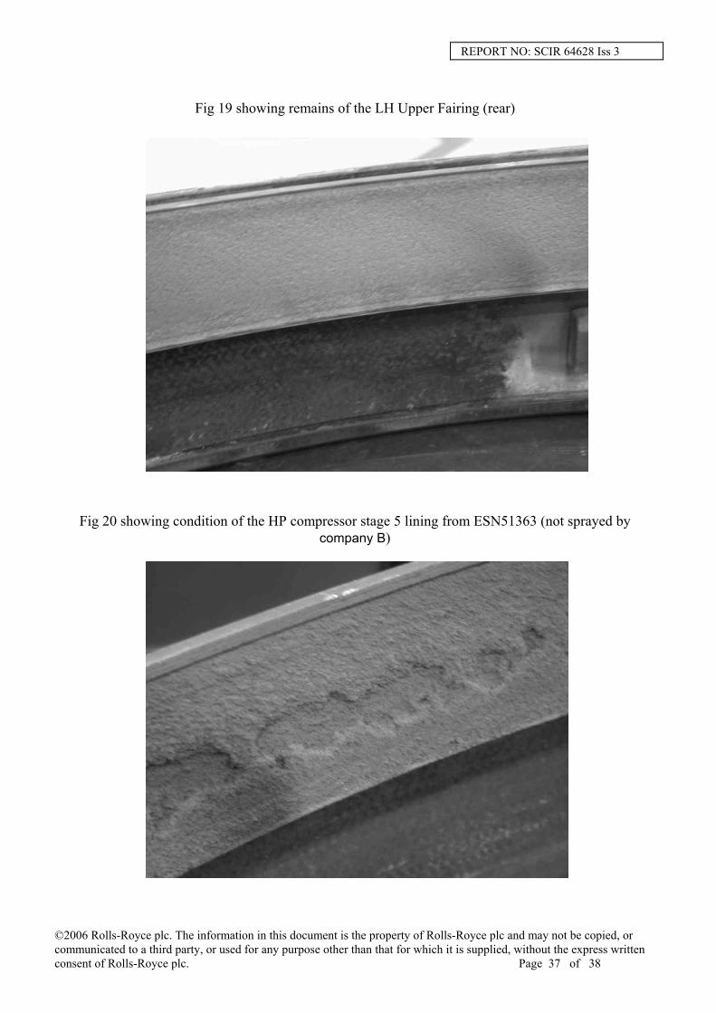
Fig 19 showing remains of the LH Upper Fairing (rear)
Fig 20 showing condition of the HP compressor stage 5 lining from ESN51363 (not sprayed by company B)
©2006 Rolls-Royce plc. The information in this document is the property of Rolls-Royce plc and may not be copied, or communicated to a third party, or used for any purpose other than that for which it is supplied, without the express written consent of Rolls-Royce plc. Page 37 of 38

REPORT NO: SCIR 64628 Iss 3
Fig 21 showing condition of the HP compressor stage 6 lining from ESN51363 (sprayed by company B)
Fig 22 showing condition of the HP compressor stage 5 lining from ESN51058 (not sprayed by company B)
Fig 23 showing condition of the HP compressor stage 6 lining from ESN51058 (sprayed by company B)
©2006 Rolls-Royce plc. The information in this document is the property of Rolls-Royce plc and may not be copied, or communicated to a third party, or used for any purpose other than that for which it is supplied, without the express written consent of Rolls-Royce plc. Page 38 of 38