Service Bulletin Wch Rt-82 Issue2
20
TECHNICAL BULLETIN At your convenience Concerned products All Wärtsilä 2-stroke engines. Preventive action To ensure trouble-free operation of Wärtsilä 2-stroke engines with distillate fuels, it is important to read the information and follow the recommendations stated in this bulletin. Validity Before taking any action, always check the available on line systems for the latest revision of this document. Any locally stored or printed version is considered to be an uncontrolled document Note This Technical Bulletin Issue 1 supersedes the Service Bulletin RT-82, dated 29.06.2009, entitled “Distillate Fuel Use”. Wärtsilä Switzerland Ltd. Tel (24h): +41 52 262 80 10 PO Box 414 CH-8401 Winterthur [email protected] Issue 2, 01 December 2014 Opera tion on disti llate fuels Information to all Owners and Operators of all Wärtsi lä 2-stroke engines RT-82 Wärtsi lä 2-stroke Technical Services
Transcript of Service Bulletin Wch Rt-82 Issue2

8/10/2019 Service Bulletin Wch Rt-82 Issue2
http://slidepdf.com/reader/full/service-bulletin-wch-rt-82-issue2 1/20
TECHNICALBULLETIN
At your convenience
Concerned products
All Wärtsilä 2-stroke engines.
Preventive action
To ensure trouble-free operation ofWärtsilä 2-stroke engines with distillatefuels, it is important to read the informationand follow the recommendations stated inthis bulletin.
Validity
Before taking any action, always check theavailable on line systems for the latestrevision of this document. Any locallystored or printed version is considered tobe an uncontrolled document
Note
This Technical Bulletin Issue 1 supersedesthe Service Bulletin RT-82, dated
29.06.2009, entitled “Distillate Fuel Use”.
Wärtsilä Switzerland Ltd. Tel (24h): +41 52 262 80 10
PO Box 414
CH-8401 Winterthur [email protected]
Issue 2, 01 December 2014
Operation on disti llate fuels
Information to all Owners and Operators of allWärtsi lä 2-stroke engines
RT-82Wärtsi lä 2-stroke
Technical Services

8/10/2019 Service Bulletin Wch Rt-82 Issue2
http://slidepdf.com/reader/full/service-bulletin-wch-rt-82-issue2 2/20
TECHNICAL BULLETIN
RT-82, Issue 2, Page 2 / 20
Contents
Page
1
Introduction 2
2 Emission control regulations 3
3
System proposal of fuel system 5
4 Fuel Change over procedure 7
5
Engine component design considerations 11
6 Contacts 20
1 Introduction
This Technical Bulletin RT-82, Issue 2, provides information and guidance concerningthe latest Emission Control Areas (ECA) regulations and fuel changeover of Wärtsilä
2-stroke engines, as well some engine components design considerations to be
followed when using distillate fuels.
NOTE:
• This Technical Bulletin supersedes the Service Bulletin RT-82, dated 29.06.2009,
entitled “Distillate Fuel Use”. Distillate fuel specifications, fuel changeover and
engine components design considerations of Wärtsilä 2-stroke engines are now
incorporated in this new document.
Wärtsilä Switzerland allows its 2-stroke engines to be operated on all distillate fuels
supplied under the ISO 8217-2012, with the exception of the distillate grade DMX
which has a viscosity and flash point too low.
The availability of fuels with various sulphur levels depends on the crude oil, the
refining technology and the region. The demand for sulphur content in the Emission
Control Area (ECA) will be decreased below 0.1% in January 2015. Thus, it is possible
that only distillate fuel will be available to meet the sulphur limits. In many aspects
distillate fuels are different to HFO. Generally, the quality of distillate fuel is more strictly
specified and better than residual fuel. Ignition and combustion properties are observed
to be significantly different for this type of fuel compared to heavy fuels.
According to ISO 8217-2012, distillate fuels are categorized as DMX, DMA, DMZ (also
called MGO) and DMB (also called MDO). DMX is a fuel used in some emergency
generators with a lower flashpoint and viscosity, thus it requires additional storage
precautions. Due to the low flash point and viscosity, DMX is not suitable for use in
2-stroke marine diesel engines. DMA, DMZ and DMB are the most common distillate
fuels. These fuels have good ignition properties because of the specified cetane index.
The DMB fuel contains up to 15% HFO and has a lower specified minimum cetane
index. It is important to ensure that the distillate fuel has adequate viscosity and anti-
wear properties in accordance with the ISO 8217:2012 specification.
8/10/2019 Service Bulletin Wch Rt-82 Issue2
http://slidepdf.com/reader/full/service-bulletin-wch-rt-82-issue2 3/20
TECHNICAL BULLETIN
RT-82, Issue 2, Page 3 / 20
The Cetane Number (determined by standardized engine test) or the Cetane Index
(found by calculation) are used to estimate the ignition properties of a distillate fuel.
The ignition and combustion properties are very important for medium-speed and high-
speed engines. Poor quality fuel are now frequently and widely found. The properties offuel is at the root of more than 50% of all cases of problem in large 2-stroke engines
(source: Brookes Bell marine investigation and consultancy).
With regards to air pollution, the international maritime legislation is laid out in
MARPOL Annex VI. Within this legislation and with regards to limiting pollution by
sulphur, the maximum sulphur content of the fuel used is defined. Alternatively, if this
cannot be complied with, approved alternative methods can be employed to reduce
sulphur emissions in the exhaust gas. For more information about the latest and
mandatory legislation, see paragraph 2 entitled “Emission control regulations”
ATTENTION:For additional information about the distillate fuel oil requirements and quality limits at
engine inlet for all Wärtsilä 2-stroke engines, see the latest issue of the
Data & Specifications bulletin RT-126, entitled “Diesel engines fuels”.
2 Emission control regulations
The International Marine Organization (IMO), with the ratification of MARPOL Annex VI
legislation, sets the maximum acceptable limits of sulphur and nitrogen compounds, as
well as the alternative strategies in terms of emission reductions.
The IMO maximum sulphur requirements can be summarized as follows:
2.1 Marine sulphur limits outside Emission Control Areas
Table 1
Date Sulphur percentage (%) limit s
From 01.01.2012 3.50% m/m
From 01.01.2020 *)
0.50% m/m
*1)
Limit will be reviewed to be completed by 2018 to determine the availability of fuelin compliance with global limit 0.50% in 2020. Based on this information parties will
defer the date of becoming effective until 1 January 2025.
2.2 Emission Control Areas
Table 2
Date Remarks
From 01.07.2010 1.00% m/m sulphur limit
01.02.2012 North America ECA implementation date01.01.2014
US Caribbean sea ECA implementation date (Puerto Rico andUS virgin islands)
From 01.01.2015 0.10% m/m sulphur limit

8/10/2019 Service Bulletin Wch Rt-82 Issue2
http://slidepdf.com/reader/full/service-bulletin-wch-rt-82-issue2 4/20
TECHNICAL BULLETIN
RT-82, Issue 2, Page 4 / 20
2.3 USA, California and North America Regulation
The California Air Resource Board has defined a region in which only distillate fuels of
grade specific maximum sulphur content are permitted to be used. This region is
24 nautical miles from the California shoreline, or from the shoreline of the ChannelIslands off the California coast.
Table 3
Date MGO (DMA,DMZ) MDO (DMB)
1 August 2012 1.0% by weight 0.5% by weight
1 January 2014 0.1% by weight 0.1% by weight
ATTENTION:Scrubber technology is not allowed in this area except on an experimental research
basis. CARB regulations will be superseded my IMO legislation in 2015.
2.4 European Union regulation
The 2012 review of the EU legislation included the latest MARPOL Annex VI
regulations with the following additional requirements:
• In EU waters outside ECAs, the fuel sulphur limit will change from 3.50% m/m to
0.5% m/m from 1 January 2020. This is irrespective of any delay agreed by IMO in
relation to the corresponding MARPOL Annex VI requirement. Until that time the
existing 1.50% m/m limit for scheduled service passenger ships remains in place.
The 0.10% m/m sulphur limit will be retained in respect of fuels used by ships while
at berth.
• Fuel with more than 3.50% m/m sulphur will only be allowed to be sold to and used
by ships equipped with an approved closed loop exhaust gas cleaning system (i.e.
no discharge of wash water overboard).
The European Parliament Directive 2009/30/EC defined that as of 1 January 2011 the
sulphur content of fuels used by inland waterway vessels is limited to a maximum of0.0010% m/m (10 mg/kg).

8/10/2019 Service Bulletin Wch Rt-82 Issue2
http://slidepdf.com/reader/full/service-bulletin-wch-rt-82-issue2 5/20
TECHNICAL BULLETIN
RT-82, Issue 2, Page 5 / 20
3 System proposal of fuel system
Figure 1: System proposal of f uel oil system for all Wärtsilä 2-stroke engines.

8/10/2019 Service Bulletin Wch Rt-82 Issue2
http://slidepdf.com/reader/full/service-bulletin-wch-rt-82-issue2 6/20
TECHNICAL BULLETIN
RT-82, Issue 2, Page 6 / 20
Table 4: Fuel system com ponents from Figure 1
001. Main Engine
002. Three way valve, Manually orremotely operated
003. Fuel oil suction filter, heated
(trace heating acceptable)
004. Low pressure feed pump
005. Pressure regulating valve
006. Automatic self-cleaning filter 10
micron, heated (trace heating
acceptable)
007. Flowmeter
008. Mixing unit, heated and insulated
009. High pressure booster pump010. Fuel oil end-heater
011. Fuel oil cooler
012. Automatic fuel changeover unit
013. Viscosimeter
014. Fuel oil filter, 60 micron, heated
(trace heating acceptable)
015. MDO settling tank
016. Pipe reduction
019. HFO settling tank, heated and
insulated
020. LSHFO settling tank, heated and
insulated021.HFO service tank, heated and
insulated
022. LSHFO service tank, heated and
insulated
023. MGO service tank
024. Suction filter
025. HFO/LSHFO separator supply
pump, with safety valve 1)
026. HFO/LSHFO pre heater
027. Self-cleaning HFO/LSHFO
separator 2)
028. Three-way valve, diaphragm
operated
029. Sludge tank
030. Fuel oil leakage tank 3)
033. Self-cleaning MDO separator 2)
034. Separator supply pump. With safety
valve 1)
035. MDO suction filter
036. MDO-pre heater
A) The return pipe can also be connected to the HFO service tank (see Figure 1).1) Pump can be omitted if integrated in the separator.
2) Separator capacity is related to the viscosity in accordance with the instructions of
the separator manufacturer and the certified flow rate.
3) A second fuel oil leakage tank can be considered to collect HFO and distillate fuel
leakages separately.

8/10/2019 Service Bulletin Wch Rt-82 Issue2
http://slidepdf.com/reader/full/service-bulletin-wch-rt-82-issue2 7/20
TECHNICAL BULLETIN
RT-82, Issue 2, Page 7 / 20
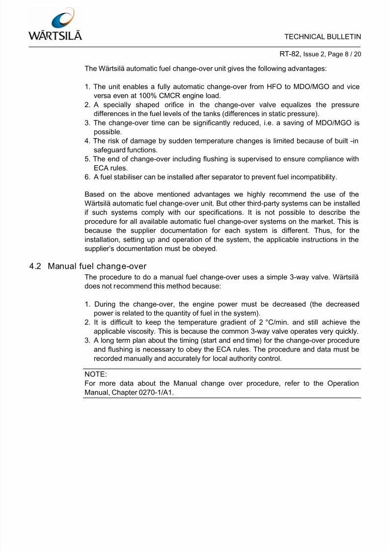
4 Fuel Change over procedure
When changing over from HFO to MDO/MGO and vice versa, thermal stress of the
related fuel components due to severe temperature changes, must be kept as low as
possible. Too rapid changes in temperature can cause the fuel pump plungers to seize,
which can cause leakages in the fuel pipes. This can also have an effect on the
manoeuvrability of the ship, with a system shutdown being the worst case.
When changing over from one fuel type to another, the temperature gradient of
2 °C/min. should not be exceeded and must be monitored in addition to the required
viscosity grade (minimum 2 cSt for MDO/MGO). In our previous specification, we
accept even a temperature change up to 15 °C/min. However, this higher limit was
based on the consideration that the fuel change-over was not done frequently (only in
exceptional circumstances). These days, when ships enter and leave ECAs more
frequently, it is recommended that the temperature change is kept as close as possibleto 2 °C/min. This will prevent a negative impact on the long-term reliability of
continuous fuel change-over procedures. The temperature gradient must also be
decreased because of the larger differences in viscosity between MGO and HFO,
relative to historical values.
4.1 Automatic fuel change-over
Wärtsilä recommends the use of an automatic fuel change-over unit (preferably
supplied from Wärtsilä), as shown in the system proposal in the Marine Installation
Drawing Set (MIDS) and in Figure 1 of this document. This type of unit has the
functions that follow:
• Internally monitors the fuel temperature
• Controls the operation of the cooler to change the fuel to the necessary viscosity.
If the fuel temperature changes too quickly, (i.e. temperature increase/drop is more
than the recommended 2 °C/min.) the system automatically stops operation
momentarily, then starts again. This keeps the mean temperature change to a
maximum of 2 °C/min. (the target is to achieve an almost linear characteristic). For the
correct installation, setting and appropriate operation refer to the data in the fuel
change-over unit Installation and Operation Manuals.
8/10/2019 Service Bulletin Wch Rt-82 Issue2
http://slidepdf.com/reader/full/service-bulletin-wch-rt-82-issue2 8/20

8/10/2019 Service Bulletin Wch Rt-82 Issue2
http://slidepdf.com/reader/full/service-bulletin-wch-rt-82-issue2 9/20
TECHNICAL BULLETIN
RT-82, Issue 2, Page 9 / 20
4.3 Manual fuel change over from HFO to MDO/MGO
ATTENTION:
This procedure is not valid for W-X62 and W-X72 engines.
When an automatic change-over system is not installed, or an automatic change-over
system has become defective, do the procedure that follows:
1. When the engine operates with MDO/MGO for a long period, the cylinder lubricating
oil must be changed to an applicable Base Number (BN). For more data about
cylinder lubricating oil, refer to Data & Specifications bulletin RT-138, entitled
“Lubricating Oils”.
2. The fuel change-over must be completed in open waters before entering the ECAand with sufficient time to complete the system flushing.
3. Trace heating of the fuel system must be set to off approximately one hour before
change-over, to prevent an increased temperature of the fuel pipes. The accurate
time is related to the pipe diameter and waste heat in the system. The viscometer
setting must be increased to 17 cSt to decrease the temperature of the HFO.
For W-X35 and W-X40 engines this setting value must be increased to 20 cSt.
4. All heating sources in the system (e.g. the fuel heaters) must be set off some
minutes before the change-over.
5. During Manual change-over from HFO to MDO/MGO decrease the engine power
(e.g. according to service experience in the range of 40% to 50% CMCR power).
The power to which to decrease is related to the total quantity of the fuel circulatingin the system, i.e. the bigger the mixing tank, the less decrease in load is necessary.
6. The recommended maximum temperature decrease of 2 °C/min. must be kept
during the change-over procedure.
7. If a continuous temperature change of maximum 2 °C/min. is not possible (after
each step of temperature change), keep the temperature change constant at a
maximum of 2 °C/min. The target is to get an almost linear property.
8. If the cooler is not started, a small viscosity decrease below 2 cSt cannot be
prevented. Thus when the fuel is at a temperature near the applicable value, you
can start the cooler slowly. This will give a linear and smooth temperature change
and minimum viscosity.
9. Normally the fuel return from the engine goes back to the mixing unit. If the return
goes back to the service tank, do not change-over the return to the MDO/MGO
service tank before the entire system (e.g. all system components such as pumps,
filters etc.) are completely flushed and filled with MDO/MGO.

8/10/2019 Service Bulletin Wch Rt-82 Issue2
http://slidepdf.com/reader/full/service-bulletin-wch-rt-82-issue2 10/20
TECHNICAL BULLETIN
RT-82, Issue 2, Page 10 / 20
4.4 Manual fuel change-over from MDO/MGO to HFO
1. When the engine operates with HFO, the cylinder lubricating oil must be changed to
an applicable Base Number (BN). For more data about cylinder lubricating oils, refer
to Data & Specifications bulletin RT-138, entitled “Lubricating oils”. Monitor the fuelreturn to make sure that HFO does not go into the MDO/MGO service tank.
2. Set the Trace Heating to ON immediately before the first step of the change-over
procedure. Engines with very large fuel rails take longer for the fuel to increase in
temperature.
3. Move the 3-way valve from MDO/MGO to HFO. HFO will then flow into the system.
When the Viscosimeter is set to 13 cSt, the pre-heater will start to operate to
achieve that.
4. The recommended maximum rate of temperature increase is 2 °C/min. during the
change-over procedure. If a continuous temperature change of 2 °C/min. is not
possible after each valve adjustment, make sure that the fuel temperature is stable.
If the temperature is stable, you can then continue the procedure. This will keep the
mean temperature change to 2 °C/min.
5. It is recommended that the engine power stays at less than 75% CMCR (This has
been established from service experience). The decrease of the engine power is
related to the total quantity in the fuel system i.e. the larger the mixing tank, the less
decrease in load is necessary.
4.5 Starting RT-flex, W-X82 and W-X92 engines on MDO/MGO
The first start on MDO/MGO may be hampered due to cold ICU control oil. In case of
such experience, repeatedly activate in flexView “Fuel Venting (all)” and manually
open/close the exhaust valves several times before engine start.
8/10/2019 Service Bulletin Wch Rt-82 Issue2
http://slidepdf.com/reader/full/service-bulletin-wch-rt-82-issue2 11/20
TECHNICAL BULLETIN
RT-82, Issue 2, Page 11 / 20
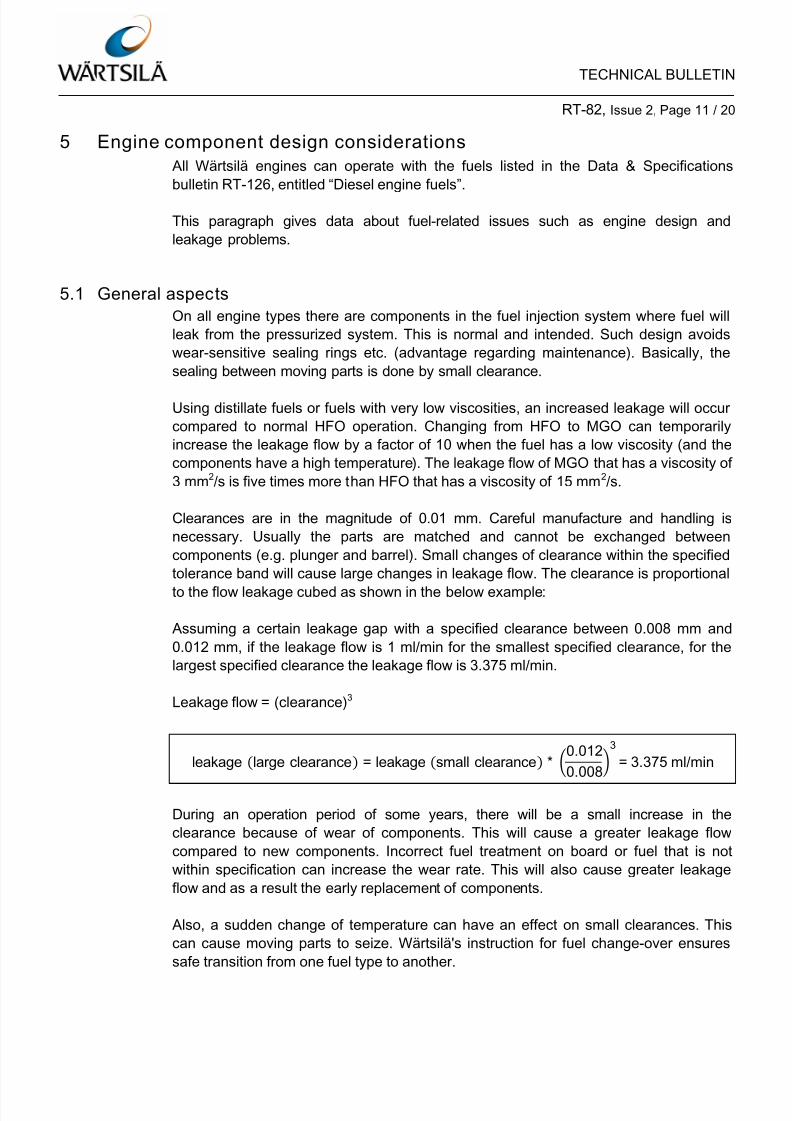
5 Engine component design considerations
All Wärtsilä engines can operate with the fuels listed in the Data & Specifications
bulletin RT-126, entitled “Diesel engine fuels”.
This paragraph gives data about fuel-related issues such as engine design and
leakage problems.
5.1 General aspects
On all engine types there are components in the fuel injection system where fuel will
leak from the pressurized system. This is normal and intended. Such design avoids
wear-sensitive sealing rings etc. (advantage regarding maintenance). Basically, the
sealing between moving parts is done by small clearance.
Using distillate fuels or fuels with very low viscosities, an increased leakage will occur
compared to normal HFO operation. Changing from HFO to MGO can temporarily
increase the leakage flow by a factor of 10 when the fuel has a low viscosity (and the
components have a high temperature). The leakage flow of MGO that has a viscosity of
3 mm2/s is five times more than HFO that has a viscosity of 15 mm2/s.
Clearances are in the magnitude of 0.01 mm. Careful manufacture and handling is
necessary. Usually the parts are matched and cannot be exchanged between
components (e.g. plunger and barrel). Small changes of clearance within the specified
tolerance band will cause large changes in leakage flow. The clearance is proportional
to the flow leakage cubed as shown in the below example:
Assuming a certain leakage gap with a specified clearance between 0.008 mm and
0.012 mm, if the leakage flow is 1 ml/min for the smallest specified clearance, for the
largest specified clearance the leakage flow is 3.375 ml/min.
Leakage flow = (clearance)3
leakage (large clearance) = leakage (small clearance) * �0.012
0.008
3
= 3.375 ml/min
During an operation period of some years, there will be a small increase in the
clearance because of wear of components. This will cause a greater leakage flow
compared to new components. Incorrect fuel treatment on board or fuel that is not
within specification can increase the wear rate. This will also cause greater leakage
flow and as a result the early replacement of components.
Also, a sudden change of temperature can have an effect on small clearances. This
can cause moving parts to seize. Wärtsilä's instruction for fuel change-over ensures
safe transition from one fuel type to another.

8/10/2019 Service Bulletin Wch Rt-82 Issue2
http://slidepdf.com/reader/full/service-bulletin-wch-rt-82-issue2 12/20
TECHNICAL BULLETIN
RT-82, Issue 2, Page 12 / 20
Fuel leakages can be divided in three groups:
1. Unwanted leakages: this is mostly leakage from incorrectly installed high pressure
(HP) pipes. These pipes are designed with a double wall or with protection hoses. Ifthere is damage to the HP pipes, loose sealing surfaces or incorrect installation,
leakage will drain safely and an alarm will be activated. On some engine types,
overpressure safety valves are installed, which drain the fuel to the fuel leakage or
fuel return system. During usual operation, this type of leakage must be zero. For
more data, refer to the applicable engine Manuals.
2. Leakages, which are returned to the pressurized fuel system. This is usual engine
operation. It will usually not be noticed by operator as a “leakage”, because it
automatically returns to the normal fuel system (e.g. fuel leakages from the injector
needle).
3. Leakages, which must be drained from the engine without backpressure. Also this is
usual leakage (e.g. from fuel pumps). Usually the leakages give in paragraph 1. are
connected to the same leakage tank. If the fuel drains into an isolated fuel drain
tank, the fuel can be used again, but not if the fuel has drained into a common waste
oil tank. The separate drain tank for such fuel leakages is standard for Wärtsilä’s
interface recommendation. Before changing fuels, it is recommended, that all
affected tanks are empty and the possibilities of mixing fuels are minimized.
During engine operation, the change of fuel between HFO and MGO will have an effect
on some performance parameters.
• Satisfactory combustion can change the quantity of injected fuel mass.
• Fuels DMA, DMZ, and DMB have lower densities than HFO, which results in a net
decrease in the calorific values per volume.
• Density of HFO is decreased compared to nominal values (normally given at 15 °C)
because the temperature of the fuel must be increased to get the applicable
viscosity.
• Fuel leakages are larger, when engines operate with MGO/MDO compared to HFO.
This causes a small increase in volume of MGO/MDO, which must be injected
compared to HFO. This (small) difference can be seen when the fuel command signal(RT-flex engines) or load indication (fuel pumps on RTA engines) are compared. This
data is described in the paragraphs that follow.

8/10/2019 Service Bulletin Wch Rt-82 Issue2
http://slidepdf.com/reader/full/service-bulletin-wch-rt-82-issue2 13/20
TECHNICAL BULLETIN
RT-82, Issue 2, Page 13 / 20
5.2 RTA engine design
RTA fuel injections pumps use dedicated valves to control the start and stop of
injection. Fuel leakage appears at the plunger and guide of the pushrods for suction-
and spill valve. The leakage of fuel cannot mix with the lubricating oil. If all drains areclear leakage is collected and drained from intermediate space in the fuel pump.
1. Suction valve
2. Leakage from suction valve
3. Delivery valve
4. Leakage from delivery valve
5. Spill valve
6. Leakage from spill valve
Figure 2: RTA fuel injection pump common leakages
Regular checks must be done to make sure that:
• The bottom spring carrier plunger has no fuel residue that can decrease the fuel
drainage.
• All drain bores in the spring carrier umbrella are clear.
Do a check of the relief valve (safety valve) on RTA injection pumps for indications of
operation (because of overpressure). Refer to the Operation and Maintenance
Manuals.
ATTENTION:
RTA82, RTA38 and RTA48 engines have fuel injection pumps with the jerk-typeplunger. For more data, refer to the applicable Operation Manual.
1
3
2
4
6
5

8/10/2019 Service Bulletin Wch Rt-82 Issue2
http://slidepdf.com/reader/full/service-bulletin-wch-rt-82-issue2 14/20
TECHNICAL BULLETIN
RT-82, Issue 2, Page 14 / 20
A higher load index can be related to an increased terminal shaft position of the
governor. On some engines, this could put a limit on the engine load because of the
governor torque and/or scavenge air limiters. If an engine must operate on low
viscosity fuels for a long period, it could be necessary to adjust the governor. Thecrankshaft torque must not be more than the maximum limit during a change-over back
to standard fuel. Speak to the nearest Wärtsilä representative if the procedures above
are necessary. Refer to the Technical Bulletin RT-121, which specifies the relation
between the engine and propeller.
When low viscosity fuel is used, different ignition properties can be seen compared to
HFO operation. This can result in high firing pressures which can have a negative
effect on the reliability of the piston rings and other combustion space components.
When a low viscosity fuel is used, measure the firing pressures and retard the timing to
compensate this peak, or operate at decreased power output of approximately
75% MCR maximum. On all RT-flex, RLA, RLB, most RTA and some RND-M enginesthe FQS can be used to retard the timing. On all other RTA engines without FQS,
adjust the fuel pump cams to retard the timing.
The pressure increase is different for each engine type and rating. Use the original
Factory Acceptance Test and or sea trial data for the reference values. If this data is
not available, speak to Wärtsilä representative to get the data. Also, refer to the
Operation Manual, 0420-1/A1 “special procedures during operation” about these
engine adjustments. The pressure compensation procedure must be done for each
batch of fuel (all grades), which will help to get the best engine performance.
Another source of leakages from the high pressure system is the fuel injection valves,
where fuel leaks along the needle guide in the nozzle element. This fuel drain is not
connected to the leakage system. This part for the fuel pipes of RTA engines is
connected to the fuel outlet of the engine (to the fuel circulation system). Therefore
operators will not see this fuel quantity as leakage. Usually, this part of the fuel system
has a pressure of between 4 bar and 5 bar to prevent cavitation damage in some areas
of the injector.

8/10/2019 Service Bulletin Wch Rt-82 Issue2
http://slidepdf.com/reader/full/service-bulletin-wch-rt-82-issue2 15/20

8/10/2019 Service Bulletin Wch Rt-82 Issue2
http://slidepdf.com/reader/full/service-bulletin-wch-rt-82-issue2 16/20
TECHNICAL BULLETIN
RT-82, Issue 2, Page 16 / 20
There are different generations and design variants of ICUs installed on RT-flex
engines. All ICUs are connected to the drain system to the overflow tank. No back-
pressure is permitted in this area. Fuel leakage that flows from this area is part of usual
operation, see Figure 4.
1. ICU block
2. Injection control piston
3. Leakage from the piston rod guide
4. Injection Control Valve (ICV)
5. Distance pin
6. Leakage from distance pin
Figure 4: Injection Con tro l Unit size 0 for RT-flex48T-D, RT-flex50, RT-flex50-B and
RT-flex50-D engines
Other ICUs with a different functional design have an added leakage connection that is
connected to the pressurized fuel system. This permits the decrease of the fuel
leakage quantity to the overflow tank. An example of the ICU from an RT-flex82T
engine is shown in Figure 5.
13
2 5
4
6

8/10/2019 Service Bulletin Wch Rt-82 Issue2
http://slidepdf.com/reader/full/service-bulletin-wch-rt-82-issue2 17/20
TECHNICAL BULLETIN
RT-82, Issue 2, Page 17 / 20
1. Injection Control Unit
2. Fuel leakage connection without back
pressure
3. Fuel return to system (4 bar to 5 Bar)
Figure 5: Injection Cont rol Unit size 3 for RT-flex82T
Leakage drains that are not pressurized are usually part of the system that monitors
fuel leakage of the HP pipes. Level switches monitor and identify these leakages. Make
sure that all drain pipes and bores are clear, which will prevent alarms that are not
necessary. The leakage flow will increase, when MGO/MDO is used. The steam trace
heating must be set to off every time when low viscosity fuel is used (some engines
might have an electrical trace heating or thermal oil instead of steam). Otherwiseexcessive leakage flow will appear and damages on fuel injection components might
happen.
Increased leakage through from ICUs causes a faster pressure decrease in the fuel
rail, when the engine is stopped. This can cause a small increase in the starting air
when manoeuvring.
1
2
1
3

8/10/2019 Service Bulletin Wch Rt-82 Issue2
http://slidepdf.com/reader/full/service-bulletin-wch-rt-82-issue2 18/20
TECHNICAL BULLETIN
RT-82, Issue 2, Page 18 / 20
Fuel leakages also drain from the fuel pumps installed on the supply unit. Fuel will leak
through the small gap between pump cylinder and plunger. As with any other
component, leakage flow will increase when MGO/MDO are used compared to HFO
operation.
Increased leakage from fuel pumps does not have an effect on engine performance.
These fuel pumps supply fuel to keep pressure in the fuel rail. There is no effect on
injection timing etc. The pressure controller on the fuel rail will automatically adjust the
leakage from the fuel pumps and ICUs. This will have the effect of a higher actuator
position.
The fuel pump has an isolated drain space with O-rings. Make sure these O-rings are
in good condition. The oil leakage drains from the engine through the drain pipes. It is
necessary to ensure drains are clear (refer to the related Operation and Maintenance
Manuals).
When the engine is running on DMA, DMZ or DMB grade fuel and the fuel change-over
is completed, the remaining heavy fuel can be drained. Trace heating must be set to off
when engine is running on low viscosity fuels. Ensure this is set to ON again for the
use of HFO.
The combustion will change compared to HFO and allowance must be made for high
firing pressures. Refer to the Operation Manual in the section 0420-1/A1 Special
Procedures during Operation to get information about these engine adjustments.
RT-flex electronically controlled engines can be adjusted to achieve the correct
maximum pressure by making adjustments using the software.
1. Fuel inlet2. Fuel leakage
3. Bore for lifting device
4. Fuel outlet5. Lube oil inlet
Figure 6: Fuel oil pump
1
5
4
3
2

8/10/2019 Service Bulletin Wch Rt-82 Issue2
http://slidepdf.com/reader/full/service-bulletin-wch-rt-82-issue2 19/20
TECHNICAL BULLETIN
RT-82, Issue 2, Page 19 / 20
Leakages from injectors on RT-flex engines are almost the same as those on RTA
engines. The drain pipes are connected to the fuel circulation system and this drain is
not seen as leakage. Fuel injectors of different designs are installed on different
engines. On some engines, the needle element in the injector looks the same as thoseinstalled on RTA engines. Others have a spiral groove applied to the needle. The
design of the needle element has an effect on the flow rate to the fuel system, which is
considered in the design during engine development.
1. Injectors without groove in the needle
2. Injectors with groove in the needle
3. Fast injector
Figure 7: Different designs of fuel injectors
When the pressure to open an injector is adjusted, you can see the leakage. When the
capacity of the pump is low, it is possible that the pressure to open the injector is not
sufficient when low viscosity test fluid is used. In these conditions, use oil that has a
higher viscosity, which will decrease the leakage flow during the adjustment procedure.
5.4 Summary of leakage and design conditions
• On RTA and RT-flex engines, it is usual for fuel leakage to drain to the overflowtank. The wide range of operation conditions, one value cannot easily be given as a
guideline.
• Low viscosity fuels used during operation will cause a higher flow rate of fuel
leakage.
• During change-over from HFO to MGO/MDO, the leakage flow can increase
temporarily.
• Usually, it is not necessary to measure the leakage. The operator will know when
there is too much leakage when the contents of the leakage drain tank must be
moved to the service tank more frequently.
3
2
1

8/10/2019 Service Bulletin Wch Rt-82 Issue2
http://slidepdf.com/reader/full/service-bulletin-wch-rt-82-issue2 20/20
TECHNICAL BULLETIN
RT-82, Issue 2, Page 20 / 20
6 Contacts
6.1 How to contact Wärtsilä
For questions about the content of this Technical Bulletin, or if you need Wärtsiläassistance, services, spare parts and/or tools, please contact your nearest Wärtsilä
representative.
If you do not have the contact details at hand, please follow the link “Contact us” – “24h
Services” on the Wärtsilä webpage:
www.wartsila.com
6.2 Contact details for emergency issues
6.2.1 Operational support
For questions concerning operational issues, please send your enquiry to:
or phone 24hrs support: +41 52 262 80 10.
6.2.2 Field service
If you need Wärtsilä Field Service, please send your enquiry to:
or phone 24hrs support: +41 79 255 68 80.
6.2.3 Spare parts
If you need Wärtsilä spare parts and/or tools, please contact your nearest Wärtsilä
representative or your key account manager.
© 2014 Wärtsilä Switzerland Ltd. – All rights reserved
No part of this publication may be reproduced or copied in any form or by any means (electronic, mechanical, graphic, photocopying,recording, taping or other information retrieval systems) without the prior written permission of the copyright holder. Wärtsilä Switzerland Ltd.makes no representation, warranty (express or implied) in this publication and assumes no responsibility for the correctness, errors oromissions for information contained herein. Information in this publication is subject to change without notice.
Unless otherwise expressly set forth, no recommendation contained in this document or any of its appendices is to be construed asprovided due to a defect of the product, but merely as an improvement of the product and/or the maintenance procedures relating thereto. Any actions by the owner/operator as a result of the recommendations are not covered under any warranty provided by Wärtsilä and suchactions will thus be at the owners/operators own cost and expense.
NO LIABILITY WHETHER DIRECT, INDIRECT, SPECIAL, INCIDENTAL OR CONSEQUENTIAL, IS ASSUMED WITH RESPECT TO