Service-Based Architecture in 5G · In chapter 5.1, the Network Data Layer is introduced to achieve...
24
Transcript of Service-Based Architecture in 5G · In chapter 5.1, the Network Data Layer is introduced to achieve...


Service-Based Architecture in 5G Case Study and Deployment Recommendations
by NGMN Alliance
Version: V2
Date: 14-June-2019
Document Type: Final Deliverable (approved)
Confidentiality Class: P - Public
Project: Service-Based Architecture in 5G
Case Study and Deployment Recommendations
Editor / Submitter: Tao Sun(China Mobile) Dan Wang(China Mobile)
Contributors: CMCC (Tao Sun, Dan Wang, Tangqing Liu), Deutsche Telekom AG (Hans Einsiedler, Steffen Drüsedow), CATR (Zhengkun Zhang), Huawei (Lei Zhu), Interdigital (Trossen Dirk), Orange (Ben Meriem Tayeb), NTT DOCOMO (Thakolsri Srisakul), AT&T (Farooq Bari), Sprint (Serge Manning), ZTE (Jinguo Zhu), US Cellular (Sebastian Thalanany)
Approved by / Date: NGMN Board, 31st July 2019
© 2019 Next Generation Mobile Networks e.V. All rights reserved. No part of this document may be reproduced or transmitted in any form or by any means without prior written permission from NGMN e.V.
The information contained in this document represents the current view held by NGMN e.V. on the issues discussed as of the date of publication. This document is provided “as is” with no warranties whatsoever including any warranty of merchantability, non-infringement, or fitness for any particular purpose. All liability (including liability for infringement of any property rights) relating to the use of information in this document is disclaimed. No license, express or implied, to any intellectual property rights are granted herein. This document is distributed for informational purposes only and is subject to change without notice. Readers should not design products based on this document.

Contents 1 Introduction ................................................................................................................................................................. 3 2 Reference .................................................................................................................................................................... 3 3 Abbrevations and Definitions ..................................................................................................................................... 3 4 Motivation and requirements ..................................................................................................................................... 4
4.1 Challenges and requirements for 5G SBA ..................................................................................................... 4 4.2 Introduction of Stateless Services ................................................................................................................... 5
4.2.1 Impacts to Service Design for Stateless ..................................................................................................... 5 5 Case study Leverage SBA ......................................................................................................................................... 5
5.1 Distributed deployment .................................................................................................................................... 5 5.2 UPF service support in SBA ............................................................................................................................ 6 5.3 Support Edge Computing ................................................................................................................................ 6 5.4 Support Network Slicing .................................................................................................................................. 7 5.5 Roaming ........................................................................................................................................................... 8
6 Efficient implementation and deployment of SBA .................................................................................................... 9 6.1 Implementation considerations ..................................................................................................................... 10
6.1.1 Requirements ............................................................................................................................................. 10 6.1.2 Functions of the Service Messaging Platform .......................................................................................... 11 6.1.3 Implementation Choices for the Service Message Platform .................................................................... 13 6.1.4 Considerations for Transport Network Integration ................................................................................... 17 6.1.5 Considerations on Slicing .......................................................................................................................... 18 6.1.6 Considerations on Performance Benefits ................................................................................................. 18 6.1.7 Considerations on Applicability within 3GPP ............................................................................................ 19
6.2 Deployment considerations under cloud native environment ..................................................................... 20 6.2.1 Virtualization technologies for service deployment .................................................................................. 20 6.2.2 Service Deployment in Cloud .................................................................................................................... 20
7 Summary ................................................................................................................................................................... 22

1 INTRODUCTION
At the beginning of 2018, the work item of “Service-Based Architecture in 5G Case Study and Deployment
Recommendations” was approved by the NGMN Board. The main target of this document is to investigate the
following aspects, which were not covered in phase 1.
- How to make services more decoupled to achieve independent Life Cycle Management (LCM) and flexible
service deployment and management.
- How to achieve high performance, including low delay, high concurrency, high reliability, and security
- Investigate how to support roaming across different 5G core networks
- Case study for generation of network slicing and edge computing by service
- Case study and recommendations for a distribution strategy of network services
This document calls for the industry cooperation on standardisation, development and promotion of the service-
based 5G architecture.
2 REFERENCE [1] 3GPP TS23.501 “System Architecture for the 5G System”,
https://portal.3gpp.org/desktopmodules/Specifications/SpecificationDetails.aspx?specificationId=3144
[2] 3GPP TS23.502 “Procedures for the 5G System;”,
https://portal.3gpp.org/desktopmodules/Specifications/SpecificationDetails.aspx?specificationId=3145
[3] ETSI GS NFV 002: Network Functions Virtualisation (NFV); Architectural Framework
[4] “NGMN 5G White Paper”, https://www.ngmn.org/5g-white-paper/5g-white-paper.html.
[5] [CONFIG] CONFIG project, Deliverable “D0.1: Reasoning for a highly flexible and modular control plane”,
https://www.5g-control-plane.eu/documents/.
[6] “Service-Based Architecture in 5G”
https://www.ngmn.org/fileadmin/ngmn/content/downloads/Technical/2018/180119_NGMN_Service_Based_Archite
cture_in_5G_v1.0.pdf
3 ABBREVATIONS AND DEFINITIONS
CPS: Control Plane Services
CPES:Control Plane Exposure Service
NDL: Network Data Layer
Nupf: Service Based Interface for N4
PCE: Path Computation Entity
SMP: Service Messaging Platform
SR: Service Router
UPS: User Plane Services
https://portal.3gpp.org/desktopmodules/Specifications/SpecificationDetails.aspx?specificationId=3144
https://portal.3gpp.org/desktopmodules/Specifications/SpecificationDetails.aspx?specificationId=3144
4 MOTIVATION AND REQUIREMENTS
4.1 Challenges and requirements for 5G SBA
Within Digital transformation and softwarization of Service Providers’ sector, network virtualization migration path’s
ultimate phase for network architectures shall embed (built-in features) and exhibit from the outset following
properties: flexibility, programmability, reliability, resilience, multi-tenancy support, isolation and cost-effective
resource consumption all as key requirements.
Those requirements shall be mapped to corresponding capabilities and exposed by the architecture as key
enablers for 5G systems. Those capabilities shall be easily consumable via standardized open APIs and adaptable
by 5G architects / designers through dynamic processes to accommodate and fulfill the variability of SLA
characteristics associated with the diverse Network Slicing Business Scenarios (Each Network Slice type is
categorized or differentiated from others by its own SLAs characteristics).
External exposure of those capabilities is essential to 5G Service Providers in building 5G partnerships and 5G
ecosystems. This should shorten time-to-market and open up opportunities for monetizing Service Providers’ 5G
assets and for new revenue stream creation through those new extended business models beyond Service
Providers’ space and 5G assets.
From standardization standpoint, the 5G architecture must move away from traditional rigid function block based-
style (linear or P2P), of architectures that are usually monolithic, heavily coupled, non-re-usable and costly chained
under static processes and costly upgradable in case of needed changes, to fine-grained service and software
component-based style of an architecture; fully flexible to be “composable” (through functional composition-style)
and programmable, resilient, re-usable and totally decoupled.
This allows independency of SFSs (Service Facing Services) from underlying RFS (Resource Facing Services). It
also allows invoking, selecting and consuming only the needed “features” (Services) when building a given Network
Service. Besides, stateless behavior of the Service-based architecture “components” shall be supported ensuring a
clear separation of storage from processing.
The main characteristic w.r.t. deployment of such a service-based architecture is the composability, which is
associated with softwarization, hence it should be aligned with cloud native model. Therefore, cloud native
deployment flavors can be compared and contrasted per Network Slice Business Scenario basis (per user, one or
multiple Network Slice, per-service type (e.g. Voice, Internet) or per Vertical (e.g. Factory, Health, Banking).
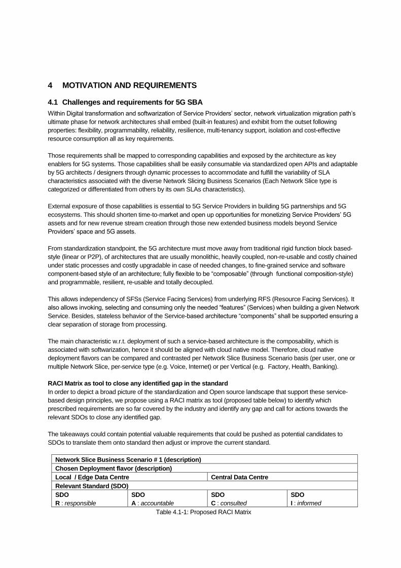
RACI Matrix as tool to close any identified gap in the standard
In order to depict a broad picture of the standardization and Open source landscape that support these service-
based design principles, we propose using a RACI matrix as tool (proposed table below) to identify which
prescribed requirements are so far covered by the industry and identify any gap and call for actions towards the
relevant SDOs to close any identified gap.
The takeaways could contain potential valuable requirements that could be pushed as potential candidates to
SDOs to translate them onto standard then adjust or improve the current standard.
Network Slice Business Scenario # 1 (description)
Chosen Deployment flavor (description)
Local / Edge Data Centre Central Data Centre
Relevant Standard (SDO)
SDO
R : responsible
SDO
A : accountable
SDO
C : consulted
SDO
I : informed
Table 4.1-1: Proposed RACI Matrix

4.2 Introduction of Stateless Services
Telecom networks which are composed of VNFs today contain both the business logic and the contextual
data related to the ongoing transactions. Such a VNF with both the business logic and the data is considered
to have “stateful” services as the instance retain the context of previous transactions handled. This makes the
association between different individual instances of VNFs more permanent. As operator networks move
towards cloud native environments, it becomes necessary that the business logic is separated out from
contextual and session related data so that it is easier to use any service instance to perform the next
transaction. This concept where only the business logic is retained in services while the contextual /
transaction related data is stored separately is called “stateless” services.
4.2.1 Impacts to Service Design for Stateless
Stateless services can use open and RESTful APIs for stateless interaction, which ensure handling of each
service transaction independently. Stateless service design requires separate data storage. The data
associate with the VNFs contains public data and private data. All the data should be stored in storage layer
rather than VNF instance. The VNF should not loss or mistaken the data when the program instance migration or
collapse. Public data contains the data defined by 3GPP, such as subscription data, subscription policy data,
structured data to be exposed or application data. The public data could be stored in UDR (according to Rel-15)
and can be accessed by VNF instance by Nudr interface. The private data contains unstructured data defined by
VNFs (e.g. instance contextual, state machine), such data can be store or retrieve in Nudsf by VNFs via N18/Nudsf
interface. Each NF service should be self-contained, when it designed by stateless. Self-contained NF service
should complete or have all the components it needs when applying its business logic, the service instance could
be managed independently from other NF services.
In chapter 5.1, the Network Data Layer is introduced to achieve the stateless service design.
5 CASE STUDY LEVERAGE SBA
5.1 Distributed deployment
The future 5G core will exist either in a central network or as a distributed network – central network and edge
networks. The number of edge networks will be between one and “m” as shown in Figure 5.1. Control Plane as well
as User Plane will be hosted in the core and the edge networks. The locations of the network services will be
depending on the requirements and characteristics of the communication functionalities.
One Control Plane (CP), which is consisted of multiple Control Plane Services, can control one or more User Planes
(UPs), which are consisted of multiple User Plane Services. The separation deployment of UPS is attributable to the
fact, that different end-user services of User Equipment (UE) have different traffic characteristics. Therefore, it makes
no sense to steer the traffic through the same UP and the UP can be optimized to manage the specific traffic
characteristics by combining different UPS.
Different Access Networks (ANs, number from 1 to “n”) are connected with the UP. The ANs either are from different
technologies or are located in different areas.
The interaction between Edge service and application (operator owned) or Customer service and application (3rd
party owned) and 5G CN is through the Control Plane Exposure Service, which is specifically described in chapter
5.3.
The Network Data Layer is an entity for context storage, which can be considered as a special service for data
storage. Services can store their data after traffic or signal processing in this distributed database, and retrieve
corresponding data before services start to work.

Figure 5.1-1: Overview of a distributed system
Please note: In Release 15 and 16, the Interface N4 is not a service-based interface (SBI). In the future, this might
be changed and it will be an SBI – Nupf. In this case, the Nupf can be connected to the Service Massaging Platform
directly or might be implemented through a direct connection between a CPS and the UPS.
5.2 UPF service support in SBA
Extending service concept to user plane can help whole 5G core network achieve high flexibility, efficiency, and
programmability. There are several benefits for introducing UPF services:
- Support cloud friendly deployment: UPF services with finer granularities and independent modules can help
take advantage of cloud-native, programmability, and flexible deployment. The service-based framework can
be leveraged to facilitate UPF services management. - Help customize user plane processing flexibly: There are multiple UPF functionalities (e.g. QoS monitoring,
MPTCP, DPI), which have been investigated and designed for different scenarios in 3GPP, and these
functionalities should be deployed on-demand. UPF service design can help dynamic and flexible deployment
of these functionalities, in terms of user plane service chaining. - Improve efficiency of service communication and easy for capability exposure: By introducing UPF services,
the direct communication between UPF services and other CP services can save duplicate data transfer and
reduce transmission path, and can also help retrieve original status or real-time service flow information from
UPF. The UPF services e.g. event exposure services, can be introduced to help UPF capability exposure.
5.3 Support Edge Computing
SBA architecture can support to deploy the services in the edge or central network flexibly. Applications owned by
operators or 3rd parties can be hosted in the core or edge networks as well. In case the CPS, UPSs, and applications
deployed in the edge network, the 5G network end-to-end latency can be reduced.
The applications deployed at the edge network can communicate with the CPS (at the edge) directly or through the
Control Plane Exposure Service (CPES).
There are some differences between CPES and NEF which is defined in 3GPP Release 15 document [1].One is that
the NEF is always deployed at the central network which may co-located with SCEF(4G entity ),or supporting for the
unified authorization of the applications interaction with 5G CP. Another difference is that the CPES may have part
CPS 10
CPS 10
CPS 10
CPS 2
CPS 3
CPS 4
CPS 6
CPS 5
CPS 1
CPS 7
CPS 8
CPS 9
AFAFAFAF3rd Party
CoreEdge 1-m
Control Plane
Communication ServiceCommunication ServiceService Messaging Platform
Data Network
Access
AN n
AN 3
AN 2
AN 1
UE2
UE1
UE3
UPS 4
UPS 3
UPS 1
User Plane 3
UPS 4
UPS 2
UPS 1
User Plane 2
UPS 4
UPS 3
UPS 2
UPS 1
User Plane 1
Control Plane communicationUser Plane connectivityNetwork to network interface
N4
N1
N2
Network slice
3rd Party services or external network service provider
Special business customer (network) services and applications
Customer services and applicationsn
Edge services and applications
Network Data Layer (NDL)
CPS 1
CPS 1CPES

of the functionalities of NEF, for example, one CPES may only support the communication between the application
with mobility service, and another CPES may only support the communication between application(s) with session
management service.
Here is an example to show how the SBA architecture can support edge computing. One typical edge computing
applications is location application. In the past, the Location Management Function (LMF) is deployed in the central
network while AN can provide specific UE location information to LMF through AMF (access and mobility
management). LMF and AMF are both deployed in the central network. Therefore, even the application is hosted in
the edge network. It has to retrieve the UE location information through LMF from the central network.
In the 5G SBA architecture, the location service can be deployed in the edge network, and any application hosted in
the edge can get the UE location through the green line in the figure 5.3-1. This aspect is not only for the edge
deployment, but also enables the 5G SBA support for the deployment of small granularity services in specific places
in a fast and flexible manner.
Figure 5.3-1 5G SBA supports the flexibly deployment of CPS and UPS to enable the edge computing
MS: Mobility Service, LS: Location Service; CPES: Control Plane Exposure Service
Another aspect for 5G SBA to support edge computing is that the UPS deployed in the edge of the network may
have simplified capability than the one deployed in the central network. 5G SBA architecture can support the design
of edge-UPS, which can be deployed fast and configured remotely. And SBA can also support the CPS and UPS
communication from different vendors based on the SBI interface design, given that the SBI interface can be updated
in fast and flexibly manner to adapt to the communication between CPS and UPS from different vendors.
5.4 Support Network Slicing
SBA will be an enabler for network slicing. A slice is defined as virtual network with special requirements given by a
customer (vertical) [4]. These requirements can be different from customer to customer. Since SBA offers a flexible
possibility to introduce different kind of network services into a virtual network, it is the perfect tool for slicing.
Figure 5.1 shows a slice, which spans from the ANs to end point of UP, where the traffic leaves operator network.
In the NGMN White Paper on 5G [4] is descripted, a slice is established to serve the same business customer. The
end-user equipment might produce traffic with different characteristics. As already mentioned, this can be taken into
account through the establishment of different UPs. The different UPs will handle the traffic differently – according to
the characteristics.

SBA architecture supports the customized 5G network based on vertical industry’s requirement. 5G SBA
architecture can support to design and deploy customized network slice in the fast and flexible way. The network
slice customization may include: interaction between different services, service capabilities, and service based
interface parameters.
Interaction between different services: 5G SBA architecture support the interaction between different services
directly (through SMP (Service Messaging Platform) without message modification), even though some interactions
have not been defined in 3GPP.
Customized service capabilities: For SBA design, the services can be simplified to support the required capabilities.
And the smaller granularity services, the easier to facilitate the service update and customization.
Customized interface parameters: based on the customized service capabilities and interactions, specific interface
parameters can be defined to simplify signal processing.
5.5 Roaming
The current roaming scenarios cover mostly home routing of the traffic. This means traffic generated by end-user
equipment connected to a visiting domain is looped back to the home domain.
Figure 5.5-1: End-user requirements connected and tunnelled to the home domain (Nupf – Interface is service
based and is not bound to a location).
Slicing together with SBA offers an excellent opportunity to optimise the network resources and the network usage.
With slicing, the home domain operator can become a customer of the visiting domain operator and can extend the
slice towards the visiting domain. This is shown in the next figure. Network Services (CPSs and UPSs) can be located
in the “rented” network resources of the visiting and home domain according to the requirements of the traffic.

Figure 5.5-2: Slice (CPS and UPSs) spans the visiting and home domain (Nupf – Interface is service based and is
not bound to a location).
Even it is possible to optimise the UPs. In certain cases, home routing is not necessary anymore but some CPSs
have to be located in the home domain. This is shown in the following figure.
Figure 5.5-3: Slice spans the visiting and home domain but the UPSs are only located in the visiting domain (Nupf –
Interface is service based and is not bound to a location).
The two models of slicing, where services of a visiting domain are used to extend the home domain slice will have
also impacts of legal issues. This has to be discussed in the future by regulatory organisations. In principle, it makes
the life easier for roaming end-users and operators.
6 EFFICIENT IMPLEMENTATION AND DEPLOYMENT OF SBA
This section provides an example of an efficient implementation and deployment of SBA, stemming from
demonstration platform insights albeit not exclusively. In this case, the basis is the separation of services
implementing the business logic (i.e., the control plane/user plane services for a particular vertical) and the service
messaging platform (SMP) providing the connectivity over the infrastructure. The SMP follows the cloud-native vision,
which foresees regionalized micro data centres interconnected over a, possible software-defined, Layer 2 wide area
network. This separation is shown in Figure 6-1 below. Through such virtualization one or more service instances
are likely to exist, realizing the business logic defined in the service they are implementing.

Figure 6-1: Service Based Architecture
Section 6.1 focuses on the implementation of the SMP and its interfacing to the services. Section 6.2 focuses on
deployment considerations, especially on those surrounding the cloud-native computing environment. Section 6.3
focuses on the aspects of network management and orchestration, which includes lifecycle management of
virtualized resources in such cloud-native deployment.
6.1 Implementation considerations
This section outlines several aspects when realizing the SBA in Figure 6-1 with a focus on the Service Messaging
Platform (SMP). We will list those considerations with insights derived from early demonstration and implementation
efforts. Note that the considerations presented in the following sections are not meant to be normative in their
adoption but merely insights derived directly from implementation for further consideration in possible standardization!
6.1.1 Requirements
Based on the cloud-native driver for the SBA work, the following requirements are being defined for the realization of
SBA solutions:
- A service instance should be reachable for incoming service request in timescales aligned with the
availability of the compute/storage/communication resource realizing the service instance: With the
increasing adoption of fast virtualization techniques, such as containers, we expect service instance, i.e.,
the virtualized realization of a service, to be ready for serving requests in very short time, such as a few
seconds or below (see also Section Fehler! Verweisquelle konnte nicht gefunden werden.). Hence, the
SMP must ensure such (newly initiated) service instance to be reachable towards other services.
- Changes in service routes should be realized in timescales aligned with the availability of the compute
resource realizing the service instance: This requirement not only captures the desire to flexibly reconfigure
service routes, e.g., based on policy changes, but also accommodate the emergence of new service
instances at fast rate in order to utilize those new service instances appropriately in service invocations.
- Service routing should be constructed based on some policies: A number of constraints should be
considered for the selection of service instances (from a set of possible ones implementing a specific
service) as well as the construction of a suitable forwarding path to the selected service instance.
Examples for such policies are shortest path, location/region-specific, delay-constrained, congestion-
constrained and others.
- Network slicing must be supported: With network slicing being a mandatory feature for 5G, the SMP may
be dedicated for a certain network slice or shared to multiple network slices. In the latter case, the SBA
shall support isolating of service instances belonging to different network slices through appropriate means,

e.g., the possibility to assign specific virtual resources to specific slices, where each slice may have
appropriate naming of service instances through the business logic realizing the services of a particular
slice. (See Section 6.1.5 for more details on enhancing service naming with network slice information).
- The SMP should support integration with Layer 2 transport networks: With the proliferation of SDN-based
networks as well as Layer 2 like overlay networks, such as those currently standardized in the IETF in the
Bit Indexed Explicit Replication (BIER) WG, any SMP solution should directly integrate with those
infrastructures. Release15 has adopted HTTP as the bearer protocol for service requests in an SBA-based
environment. However, HTTP is a mere application-level transport protocol, leaving a lot of room for the
actual service interface being used. When realizing such HTTP-based communication, we identify three
key requirements that need to be addressed. - The service interface must define the interaction that is being used for service-level communication: Apart
from a traditional request-reply interaction, we also foresee the need for publish-subscribe type interaction,
e.g., for event type notifications. Given well-documented performance issues in HTTP for long-standing
connections, the latter calls for a requirement to use HTTP/2. Ultimately, the interaction patterns and their
realization must be standardized for full interoperability of the service communication in figure 6-1.
- The service interface must define the language that is being used in the interactions: There exist many
(HTTP-based) frameworks for describing the interactions and the business logic realized by the services
on top of the SMP. For instance, Restful interactions are common practice in enterprise architectures with
plenty of tools available for realization of Restful web service implementations. The service interface must
be standardized to ensure interoperability between service implementations of different vendors.
- The service interface must define the naming scheme(s) that are being used for addressing services:
HTTP is a name-based protocol with URLs (uniform resource locators) being used to ‘point’ to resources,
i.e., service endpoints, in the network (here the control plane). The locator-based naming of URLs as well
as the ability to introduce a sub-domain is a very powerful tool that can be used for addressing several
aspects through appropriate naming of the services1. For instance, service naming scheme may include
“organizational identification”, “release identification”, “operator identification”, “slicing identification” as
described below. Alternative to enhancing the service naming scheme is to include such information into
the HTTP message header.
- Organizational identification: 3GPP standard functions could be identified through, e.g., a 3GPP
domain, such as servicex.3gpp.org, with the service x sub-domain governed through the organization
holding the domain, here 3GPP. A derivate of a well-known service for a particular vertical could be
identified through servicex.verticalA.org.
- Release identification: the name could further include release information, e.g.,
servicex.rel16.3gpp.org for identifying Service X under Release 16 specification.
- Operator identification: incorporating the mobile network code (MNC) into the name, such as
servicex.248.3gpp.org, could be used to support the roaming use case by routing service requests to
home network services, while other services could remain in the visiting network.
- Slicing identification: incorporating a slicing identification into the name could support the exposure
of service instances (i.e., VNF instances) of service X to a particular slice purely through the name,
e.g., SID.serviceX.3gpp.org. With this, the particular service instance is only exposed to other
services’ instances in said slice. We term this ability ‘soft slicing’ which could be complemented by
connectivity slicing, i.e., the establishment of suitable forwarding paths between the identified service
instances.
6.1.2 Functions of the Service Messaging Platform
This following section addresses the core operations of the service messaging platform itself. We consider that some
of those aspects are likely subject to standardization, either in the form of defining the interface interactions or the
policy definitions being conveyed to the service messaging platform.
1 Note that several of the naming aspects could be combined into a single way of service naming.

6.1.2.1 Service Registration & Discovery
An important aspect of the SMP is registration of a service and the initiation of a communication with another service.
The first step involves the registration of the service instances to the service registration & discovery sub-service of
the SMP (see Figure 6-1). Due to the cloud-native driver for SBA, we assume each registered service being realized
by one or more service instances. Hence, the registration should also include an identifier for the service instance,
which allows for the communication between specific service instances rather than the abstract service names. This
information is used in the registration service to create a mapping between network location, service instances and
service name that can later be used for the message routing sub-service of the SMP to deliver messages between
service instances.
Upon initiation of a service interaction between an instance of service x to a suitable instance of service y, the
communication request is resolved by the message routing sub-service of the SMP through a request to the service
registration and discovery sub-service, which in turn provides suitable routing information for the request to specific
service instances of CPS y that are available. Depending on the implementation of the message routing sub-service
(see Section 6.1.2.5), those resolution steps will not need to be done for every transaction if the routing information
between service x and service y instances remain the same, assuming suitable update information in place (see
again the realization of such network service in Section 6.1.2.5).
To ensure backward compatibility with Release 15, suitable discovery capabilities need to be provided that turn, for
example, service type, network slice, SUPI, and DNN information provided by a Release 15 compatible NF into
suitable service name information that is being used for the service interaction between two service instances via the
SMP.
6.1.2.2 Authentication
Authentication for message routing between service instances is focussed on the authentication of service instances
within the registration service. For this, we assume proper name authorities to be in place, implemented through
including suitable authority certificate information in the service instance registration. Additionally, access information
can be included in service invocation requests although the nature of this information depends on the services
themselves, e.g., UE information, slicing information or similar, and we expect this to be covered in the definition of
the control plane services themselves.
6.1.2.3 Failover Management
Failover in the context of the service framework considers two aspects:
- Failover of service framework components: any of the components of the service framework are subject
to failure and need appropriate failover mechanisms to ensure continued availability of service instances.
Such failover can be achieved through (i) distributed or (ii) replication realization of service framework
components. The registration service is a candidate for a replicated realization, possibly utilizing state
externalization through a separate network data layer for a stateless operation. The communication service
is a candidate for a distributed as well as replicated realization. Section 6.1.2.5 discusses two
implementation choices for these options.
- Failover of service instances: Service instances communicate through the SMP and can fail caused by,
e.g., data centre outages or SW bugs. The stateless operation of such service instances is key to realizing
a failover to another service instance. However, the SMP must provide support for such failover by
updating the service registration information. Also, if the resolution steps are realized optionally, i.e.
assuming caching of routing information between two instances, there needs to exist an update
mechanism to remove any stale information at the communication service, invoking the resolution steps
again for the next service invocation and therefore leading to a now available different service instance (if
available).

6.1.2.4 Policy Enforcement
Policy enforcement of the SMP is limited to the selection of suitable service instances as well as suitable forwarding
path between two service instance candidates (e.g., the enforcement of a specific bandwidth between them). Key
issue from a standardization as well as implementation perspective is primarily the specification of the policy, while
the conveyance of the policy is secondary (here, a specified REST interface to the SMP can be used or a policy
could be optionally provided when registering a service instance).
Load balancing affects the selection of suitable service instances as well as the selection of suitable forwarding
resources between discovered service instances. We consider ‘load balancing’ as a special case of policy
enforcement, which is covered in the next sub-section.
6.1.2.5 Message Routing
The message routing sub-service of the SMP in Figure 6-1 enables service sending request and response messages.
The message routing shall support the existence of virtual instances of services, accommodating the requirements
in Section 6.1.1. The realization of this sub-service will directly impact key performance indicators such as flow
completion, network efficiency (including path length) and others outlined in Section 6.1.6.
6.1.3 Implementation Choices for the Service Message Platform
In the following, we outline approaches to realizing the various sub-functions of the SMP in Figure 6-1, based on
exemplary technologies such as bus or service routing approaches. It is important to note that those approaches are
neither comprehensive nor limiting in terms of implementation choices.
6.1.3.1 Centralized Bus Architecture
Centralized Bus Architectures are used in messaging systems to decouple producers and consumers of messages
in order to minimize their mutual awareness and dependencies. Such architectures consist of a message broker
that takes care of message validation, transforming and routing. There are many message broker solutions
available, differing in terms of performance, reliability, flexibility and additional features sets.
While some solutions put focus on plain performance with limited support for flexible routing logic, others provide
fine-grained control of the routing decisions, support transaction management or guaranteed message delivery.
The selection of a suitable message broker depends on the requirements of the intended use-case.
The remainder of this section describes a potential realization of a message routing service based on the general-
purpose message broker RabbitMQ (https://www.rabbitmq.com), and other solutions could also be considered for
implementation.
Figure 6.1.3.1-1 illustrates the overall concept of the RabbitMQ message broker. Message producers emit messages
to a so called “exchange” through an API. Depending on the type of the exchange ( “direct”, “topic”, “headers” or
“fanout”) and the programmed bindings between exchanges and queues, the message is then pushed into one or
more “queues”. In this figure, the example of having three “topic” types, which are the key to the publication of
messages, is depicted. Finally the consumers receive and consume the messages from the queues they are
subscribed to.

Figure 6.1.3.1-1: RabbitMQ Message Broker Concept (with topic based queues)
Service Registration & Discovery
The central message broker architecture provides means to register consumers and producers through the offered
APIs. Given the topic-based realization of the RabbitMQ broker architecture, this component maps the service names
provided in the registration to an appropriate RabbitMQ topic.
Message Routing
The responsibility of the implementation logic is to initiate and maintain P2P style communication sessions as well
as the control of the actual message routing so that delivery is not implemented in the services anymore.
Authorisation
RabbitMQ provides several own mechanisms to authenticate consumers and producers and to authorise their
messaging operations in a fine-grained way, e.g. deny creation of queues or exchanges, limitations to read-only
access to queues, etc.
Policy Enforcement
In logically centralized message broker architecture, the Application and enforcement of communication related
policies is easier to achieve than in the traditional P2P style communication pattern. Policies don’t need to be
distributed over all services but can instead be managed in a central place. The responsibility for the communication
related policy enforcement is not on the services themselves anymore.
Failover Management
RabbitMQ supports different modes for a distributed deployment to ensure the operation also in case of partial node
failures. Figure 6.1.3.1-1 shows the conceptual layout of three RabbitMQ nodes that are operated in “clustered”
mode. In this mode, all nodes are sharing the same metadata, i.e. the information about which node is handling which
queues, but the queues themselves are not replicated. Nevertheless, they are visible and reachable from any node.
If more reliability is required, RabbitMQ nodes can alternatively be operated in a “high availability” mode, where also
the message queues are mirrored to one or more other nodes and are not lost if their hosting node fails.

Figure 6.1.3.1-2: RabbitMQ Clustering
For the clients, these clustering modes are transparent. As long as they can reach one of the nodes they can publish
messages to any exchange and consume messages from any queue.
The monitoring of the message forwarding queues allows detailed insights into the overall system load and can be
used to derive the “health” of individual services. The fill-level of the queues is an indicator for overload situations and
might be used to trigger healing or scaling actions.
Interaction of HTTP based services with SMP
All potential message broker solutions have their own internal protocols and specifics, supported by their own APIs.
To allow http based services the use of arbitrary message brokers, it needs a connector entity that, that converts the
http based service messages to broker specific format and back. This connector shall provide a standardized, simple
messaging API towards the HTTP-Services, hiding the complexities of the corresponding message broker and
allowing for interoperable combinations of services and broker solutions.
6.1.3.2 Distributed Message Routing Architecture
An alternative to a logically centralized message bus system is that of using distributed message routing, akin to the
operation of an IP-based system in the Internet. Hence, the service instances in one data centre are assumed to
communicate through the traditional HTTP/TCP/IP based interaction with another service instance, said remote
service instance being located in a remote data centre. Figure 6.1.3.2-1 shows an architecture for such distributed
message routing, integrated with an SDN-based transport network – we will discuss considerations for such SDN
integration separately in Section 6.1.4.
We introduce two distinct components for such distributed routing, namely the service router (SR) and the path
computation entity (PCE). Within the architecture in Figure 6.1.3.2-1 the PCE represents the service registration and
discovery sub-service of the SMP, while the SR implements the message routing sub-service of the SMP.

Figure 6.1.3.2-1: Direct Path Message Routing Realization
In a traditional IP-routed realization of Figure 6.1.3.2-1, the SR implements IP routing capability while the PCE
represents the local DNS entry point, resolving service names onto IP endpoint addresses (which in turn are used
by the SR to route incoming service requests). Section 6.1.4 outlines how such IP routing approach would integrate
with the depicted SDN-based transport network through a so-called ‘flow-based’ approach to Layer 2 forwarding.
An alternative to an IP routing system is that of utilizing service level termination, i.e., the termination of the underlying
TCP connection, at the SR with a layer 2 forwarding of the HTTP service request based on a so-called path-based
approach (see Section 6.1.4 for the transport network considerations for this approach). The service termination at
the SR results in being able to utilize the HTTP information, such as the service name as represented by the fully
qualified domain name (FQDN), to make forwarding decisions directly at Layer 2. For cases of HTTPS-based
services, the SR can either utilize the TLS handshake to obtain the FQDN information for the service name or a
certificate sharing arrangement between service and SMP provider can be in place for terminating the HTTPS-level
transaction at the SR.
Service Registration & Discovery, Message Routing
Each service instance registers with the PCE to expose the availability of the service. As a result, the service is
typically reachable within the transport network in sub-second timescales, addressing requirement - in Section 6.1.1.
Message Routing
Upon receiving an HTTP request at the SR, suitable path information is being retrieved from the PCE, which in turn
is utilized by the SR to forward the service request to the suitable service instance. SRs use long-lived flows from
one SR to another in which HTTP requests (and responses) are transported. This allow for keeping flow setup times
small since only transient service-to-SR flows need to be setup, while the flow management between SRs is longer
lived and managed.
Policy Enforcement
When receiving a path computation request from an ingress SR, policies in the PCE decide upon the selection of the
most ‘suitable’ service instance from a set of available ones, realizing the policy requirement - in Section 6.1.1.
Shortest path is the default policy while other policies could control the weights on such shortest path policies for
other, e.g., delay-constrained policies. The PCE would need to expose a policy interface for defining arbitrary policies
being applied on a per FQDN basis.
Authorisation
No specific means for authorising the routing of message is provided from the client perspective. Here, we assume
that client-server mechanisms are used to determine suitable access to server resources. Authorisation of the service

instance registration relies on the certificate binding to the FQDN of the service, i.e., including the authority certificate
into the registration to avoid non-authorised servers to register a service name.
Failover Management
Forwarding information is locally cached at the SR after having been obtained from the PCE, therefore removing any
initial latency for the PCE resolution for any future requests being sent to the service name. When new service
instances become available or existing ones disappear, the PCE performs a path update procedure2 which flushes
path information for the service name from any SR in the network, leading to a new path computation for any future
service request. This addresses requirement - in Section 6.1.1. We will see in Section 6.1.4 that both requirements
1 and 2 can be provided at small timescales since intermediary SDN switches will need no update of path information,
therefore limiting the latency to the procedures in the logically centralized PCE and the communication of path
information to the SRs.
Furthermore, the PCE service in Figure 6.1.3.1-3, implementing the service discovery and registration sub-service of
the SMP, can be replicated. Utilizing the NDL functionality in SBA realizations, the registration information can be
provided via such NDL, while the path computation functionality itself can operate entirely stateless. Hence, many
PCE entities can be deployed in the infrastructure, allowing for reducing latency (for path computation and
communication between SR and PCE) and load (for path computation) as well as enabling failover capabilities by
signalling failure of a PCE to the SRs which in turn discover another available PCE in the system.
Interaction of HTTP based services with SMP
Since the SR directly terminates HTTP sessions, no specific conversion is required and any HTTP-based service
implementation can be connected to the SMP.
6.1.4 Considerations for Transport Network Integration
Given our requirement in Section 6.1.1 on integrating with Layer 2 transport network, we focus our discussion
specifically on the integration with software-defined systems such as SDN-based transport networks. Standard IP
routing is being realized in such SDN-based transport networks through either a flow-based approach or a path-
based approach:
- Flow-based approach: Traditional IP longest prefix matching is performed through adding suitable flow
table entries to intermediary SDN switches in the transport network. Such flow insertion can be reactive or
proactive or a mix of both. Proactive insertion would distribute well-known IP address ranges and their
corresponding flow matching rules into SDN switches. In the reactive mode, the SDN switch would assert
an SDN controller interaction for an unknown prefix range upon which the SDN controller would insert the
suitable flow matching rule into the SDN switch. With this, the flow table of intermediary SDN switches
grows linearly with the address space being served by the SDN switches. Also, the reactive insertion incurs
latency for new destination ranges not yet supported by an intermediary SDN switch.
- Path-based approach: Each link of a transport network is represented by a well-defined bit3 in a bitarray.
With that, a path in a network from one location to another is represented a bitpattern within said bitarray
where all bit positions that are set to 1 represent those links included in the path. A forwarding decision at
a particular SDN switch can now be executed as a binary and operation for the bitposition assigned to
each switch-local output port. Such binary operation is executed as a ‘wildcard matching’, supported by
OpenFlow specifications V1.3 and higher, with the ‘wildcard’ being defined as the specific bitposition for
the local output port.
Extension approaches for larger-scale transport networks have been studied in addition to those available packet
header fields. The utilization of a forwarding bit pattern also allows for a fully distributed support for multicast where
one or more paths can be combined to a single multicast path through a simple binary or over all unicast bit patterns
2 The path update procedure utilizes Layer 2 multicast (with suitable paths to all SRs being combined into a single multicast tree through a simple binary OR operation – see Section 6.1.3 for more information) 3 Such bitposition is assigned during the inventory setup via an OAM system. Only changes to the inventory, e.g., through removing switches from the transport network, might require any changes to the bitposition assignment.

without incurring any state costs in the transport network itself since each intermediary SDN switch still implement
the same bit field check operation. This binary or operation is done locally in the SR component. While such multicast
support is not of importance for control plane operations, it can lead to significant performance benefits for user plane
operations through such inherent multicast support.
6.1.5 Considerations on Slicing
Two aspects need to be considered when it comes to slicing:
- Embedding a SBA realization within isolated resources: An SBA based control plane deployment can be embedded itself into an infrastructure slice that provides communication, computing and storage resources, therefore isolating resources from other SBA based control plane deployments. From an SBA perspective, if each network slice has its own SBA based control plane deployment, then there is no immediate impact on design and deployment of the SBA platform, specifically the SMP, itself. However, if some services, for example, SMP, would be in common for multiple network slices, there may be some changes required in the SMP to support multiple network slices.
- Embedding 3GPP network slicing into an SBA realization: Services within a single SBA deployment can be provided as ‘sliced services’ within the context of 3GPP compliant ‘network slicing’. This is captured through assigning one or more clients to one or more services through an association with the S-NSSAI. Within the SBA design model, the support for such slicing could be provided through, for example, appropriate service naming, e.g., serviceX.s-nssai.3gpp.org, i.e., embedding the slicing identifier into the naming structure used for the communication over the SMP. However, as also mentioned earlier, alternative is to have slicing information being included in the HTTP message header. By selecting specific service instances in the overall set of service instances to expose the additional S-NSSAI sub-domain, the resources for serviceX in terms of assigned service instances are dedicated for specific network slices.
- Backward compatibility to 3GPP Release 15: With Rel. 15 in 3GPP specifying the use of the S-NSSAI (and other parameters such as the DNN) in the discovery of a suitable service instance, the service registration & discovery function of the SMP can provide a suitable interface to resolve such Release 15 compliant input parameters into a qualified service name being used for communication, if there are differences of service naming in Rel-15 and Rel-16. Alternatively, the business logic (i.e., the service) itself can construct a suitable service name with network slicing included by utilizing well-specified naming structures with 3GPP CT4 currently studying various naming structures [TS 29.501 v15.0.12].
6.1.6 Considerations on Performance Benefits
Considerations on performance can be, for example, in terms of expected goals as well as expected bottlenecks,
considering the aspects presented in the previous sub-sections on implementation. Ultimately those considerations
are best expressed as key performance indicators (KPIs) against which the industry community can measure SMP
implementations by developing suitable test cases. Those KPIs are defined independent of any specific
implementation choices and focus on the quantitative benefits of SBA in general. Our considerations do not address
any qualitative aspects the introduction of SBA in general or specifically the transition from 3GPP Rel15 to Rel16
might bring.
We can divide our KPIs into four groups, shown in Table 6.1.6-1, addressing general performance as well as the
three quantitative requirements in Section 6.1.1.
Table 6.1.6-1: KPIs for SBA Performance Considerations
General SMP performance Requirement 1 Requirement 2 Requirements 5
Transaction Completion
time for CPS [ms]:
Base line is a direct path
HTTP/IP routed scenario
with (a) cold start, i.e.,
without possible flow re-
use and (b) warm start,
Instance availability
[ms]:
Time between registering
a service instance and its
possible inclusion into a
message routing decision
Service redirection time
[ms]:
Time between a service flow
is changed from one
instance to another
TCAM memory costs
[#flow entries]:
The size of the TCAM
entries in each switch is
an important cost factor
due to the high costs for
this memory type.

i.e., with possible flow re-
use
Reducing or limiting
TCAM costs is
therefore a crucial KPI.
Data centre throughput
[req/s]:
Number of requests that
can be served at the data
centre ingress, assuming
infinite service instance
capacity
Instance congestion
control:
Delivery time for the
transaction between the
producer and the
consumer under the
congestion situation in the
transport network. Packet
loss sensitivity under the
congestion situation
Instance failover time
[ms]:
Time to recover from a
control or user plane service
instance failure with the
selection of a suitable
alternative service instance,
i.e., the time it needs to
recover the service instance
failure once the failure is
detected until the service
instance is fully recovered.
Note that we only consider
timeouts that are specific to
SMP sub-services, such as
transport connection
timeouts, HTTP-specific
timeouts etc.
Forwarding setup
time [ms]:
This KPI specifically
addresses the possible
latency incurred
through setting up the
appropriate Layer 2
forwarding information.
Routing path stretch
[#hop/s]:
Measures routing
efficiency with most direct
path (stretch 1) desired.
Link failover time [ms]:
Time to recover from link
failure with either the
selection of a different path
to the same or a path to a
new service destination
instance, removing any
transport network latencies
for link error detection
6.1.7 Considerations on Applicability within 3GPP
Network service should focus on the business logic (i.e., the control plane/user plane services for a particular
vertical) and should not consider how the communication path is established between two service instances.
Network services are grouped into Service Sets. Within one Service Set, the capability of each service Instance are
same. The service instances within a given Service set are expected to have access to the same data layer
therefore it is the key to achieve stateless network service and failover management.
The service instance register to the Service Messaging Platform. The Service Messaging Platform is aware of the
addition, removal or failover of service instances, therefore the Service Messaging Platform can perform service
discovery. When the transaction is targeting to a service set, the Service Messaging Platform selects the service
instances within the target Service Set.
3GPP is now studying the architecture of Service Framework in FS_eSBA study. The following aspects can be
considered in FS_eSBA study
- Service Messaging Platform. The functionalities of SMP include the service registration & service discovery,
consumer authorization, message routing and failover management. - Service Set Concept. The Service set is introduced to achieve the service instance service stateless and service
failover management. - Policy Enforcement. Policy enforcement of the SMP is limited to the selection of suitable service instances as
well as suitable forwarding path between two service instance candidates. - Service based N4. The UPF can be virtualized and the N4 can use the benefit of service based interface.
Regarding the implementation of the Service Messaging Platform, there are a lot of solutions. 3GPP architecture
should allow the interconnection between the different SMPs. It is recommended to specify common interface
between the service and Service Messaging Platform, and between Service Messaging Platforms to ensure
interoperability between implementations of different vendors
6.2 Deployment considerations under cloud native environment
6.2.1 Virtualization technologies for service deployment
Cloud Native refers to a new system practice paradigm for creating, operating, and managing software in a cloud
environment. Cloud Native software design leverages cloud infrastructure services, is applicable to the cloud
environment, and support serviceability, elasticity, high availability, multi-tenancy, automation, high availability and
other features. Usually, the Cloud Native application software is based on virtualization environment.
One of the major goals of virtualization technologies is to separate application software and IT infrastructure
hardware. Virtual Machine (VM) and Container are all virtualization technologies that Cloud Native software design
is based on.
6.2.1.1 Based on VM
A virtual machine is the virtualization of hardware or platform that acts as a real computer operation environment
with an operation system. Cloud Native software runs over virtual machine is separated from hardware
infrastructure, so as more focus on software design and features that support Cloud Native features above. In
computer operation system, the typical virtual machine technologies (e.g. KVM technology) will create a host
operation system (Host OS) that take place on virtualization of actual machine, and a Guest OS controlled by Host
OS that is taken into account as virtual machine. The Guest OS will be an execution environment for application
software with distinguished virtual resources (e.g. virtual compute, virtual memory and virtual networking). The
software as part of virtualization technology for virtual machine that is responsible to create virtual machine,
manage virtual resources is called hypervisor or virtual machine management.
6.2.1.2 Based on Containers
Container in computer science area is one of virtualization technology at operation system level. Currently, a
number of container technology implementations can support virtualization, isolation, file system, and resource
management provided by Linux kernel. The typical implementations of container technologies are Docker, LXC etc.
Docker is a computer program that performs operation system level virtualization. Docker is designed and
developed based on Linux kernel, where it uses Linux kernel features to support independent operation, virtual
resource management. The container based on Docker can run over infrastructure hardware or virtual machine.
The container based on Docker will consume limited virtual resources and runs over IT infrastructure hardware, so
as to perform efficiently on virtual resource consumption.
6.2.2 Service Deployment in Cloud
In this section, possible deployments of service in a cloud environment are described.
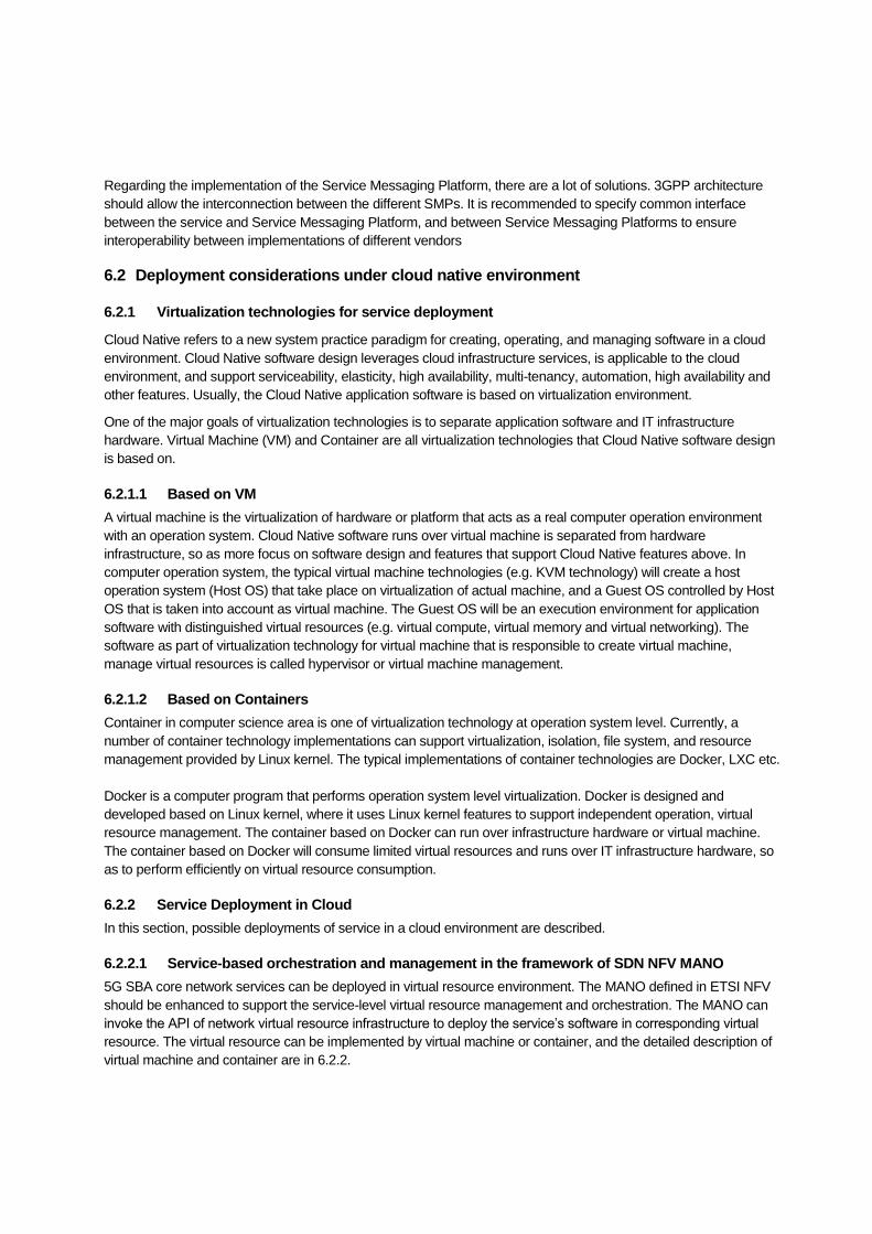
6.2.2.1 Service-based orchestration and management in the framework of SDN NFV MANO
5G SBA core network services can be deployed in virtual resource environment. The MANO defined in ETSI NFV
should be enhanced to support the service-level virtual resource management and orchestration. The MANO can
invoke the API of network virtual resource infrastructure to deploy the service’s software in corresponding virtual
resource. The virtual resource can be implemented by virtual machine or container, and the detailed description of
virtual machine and container are in 6.2.2.
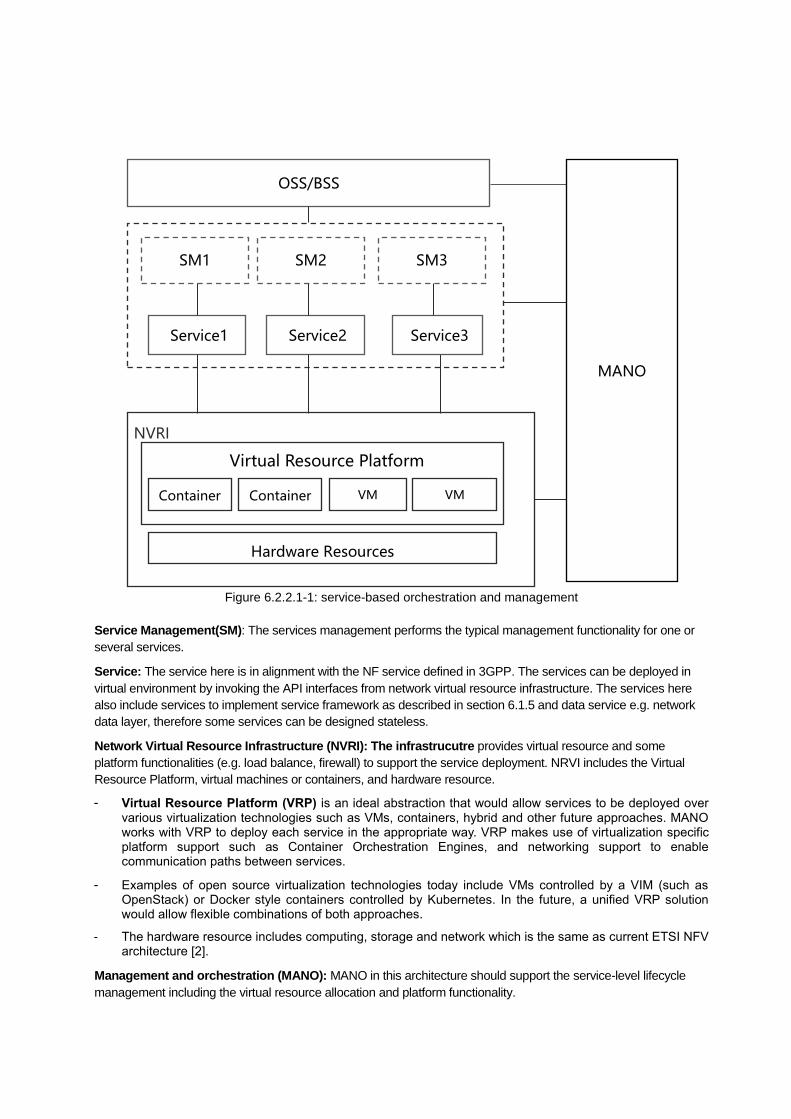
Figure 6.2.2.1-1: service-based orchestration and management
Service Management(SM): The services management performs the typical management functionality for one or
several services.
Service: The service here is in alignment with the NF service defined in 3GPP. The services can be deployed in
virtual environment by invoking the API interfaces from network virtual resource infrastructure. The services here
also include services to implement service framework as described in section 6.1.5 and data service e.g. network
data layer, therefore some services can be designed stateless.
Network Virtual Resource Infrastructure (NVRI): The infrastrucutre provides virtual resource and some
platform functionalities (e.g. load balance, firewall) to support the service deployment. NRVI includes the Virtual
Resource Platform, virtual machines or containers, and hardware resource.
- Virtual Resource Platform (VRP) is an ideal abstraction that would allow services to be deployed over various virtualization technologies such as VMs, containers, hybrid and other future approaches. MANO works with VRP to deploy each service in the appropriate way. VRP makes use of virtualization specific platform support such as Container Orchestration Engines, and networking support to enable communication paths between services.
- Examples of open source virtualization technologies today include VMs controlled by a VIM (such as OpenStack) or Docker style containers controlled by Kubernetes. In the future, a unified VRP solution would allow flexible combinations of both approaches.
- The hardware resource includes computing, storage and network which is the same as current ETSI NFV architecture [2].
Management and orchestration (MANO): MANO in this architecture should support the service-level lifecycle
management including the virtual resource allocation and platform functionality.
OSS/BSS
SM2
Service2
SM3
NVRI
Container
Service3
VM
MANO
Container
Service1
SM1
VM
Hardware Resources
Virtual Resource Platform

7 SUMMARY This white paper investigates the 5G SBA architecture from deployment perspective including:
- 5G SBA distributed deployment.
By introducing the User Plane Services and extending N4 to SBI, the 5G CN can be totally service based. The CPS
and UPS can be deployed flexibly either in central network or edge network.
- SBA as a slicing enabler.
Following [4], slicing is a virtual network, which is provided to a customer (other operators, verticals, etc.). The
service based 5G CN can help the introduction of network slicing (e.g. become much easier for services and
interfaces customization and management). Different traffic characteristics might appear which have to be
controlled through one specific control plane of the slice. Therefore, a Control Plane will control different User
Planes according to the traffic characteristic. SBA also offers an easy path to establish the two most usable
operator scenarios: Home routed and local break architectures. For the edge computing, SBA offers the choice to
distribute CPSs and UPSs in an optimal way to support the low latency requirements through a placement of the
CPSs and UPSs in an optimal location.
- 5G SBA implementation consideration, especially for the Service Messaging Platform (SMP).
The functionalities of SMP include service management, authentication, failover management, policy enforcement
and message routing. When introducing SMP, two architectures include centralized bus and distributed message
routing should be considered.
There are still some remain issues e.g. whether the SMP should be in one slice or span multiple slices.
- 5G SBA deployed in cloud native environment.
5G CN services can be deployed on virtual machine or containers, to achieve the benefit of NFV. While considering
the introduction of cloud environment, it is suggested to design the virtualization layer as PaaS platform, and 5G
CN services can be regarded as applications.

Document History
Date Version Author Changes
2018-03-27 0.0.0 China Mobile (Tao Sun), Deutsche
Telekom AG (Hans J. Einsiedler),
AT&T (Farooq Bari), Bell Canada
(Erfanian Javan), BT (Weng Choo),
NTT DOCOMO (Srisakul Thakolsri),
Sprint (Serge Manning)
Skeleton
2018-06-19 0.1.1 China Mobile (Tao Sun, Dan Wang) 6.3 update
2018-07-10 0.1.2 Interdigital (Trossen Dirk), Orange (Ben
Meriem Tayeb), China Mobile
(Tangqing Liu, Dan Wang,Tao Sun)
Interdigital contributes the text for
section 6.1; Orange contributes the text
for section 6.2;
CMCC contributes the text for section
6.3
2018-08-28 0.1.5 Interdigital (Trossen Dirk), Deutsche
Telekom AG (Steffen Drüsedow),
Orange (Ben Meriem Tayeb),
Input for section 6.1 and 5.2
2010-09-10 0.1.6 China Mobile (Tangqing Liu),
Interdigital (Trossen Dirk)
Update for section 6.3;Update for
section 6.1
2018-09-25 0.1.8 Interdigital (Trossen Dirk), NTT
DOCOMO (Srisakul Thakolsri),
AT&T(Farooq Bari)
Update for section 6.1 and section 3.1.1
and comments for 3.1.2
2018-10-22 0.1.9 Sprint (Serge Manning) Update for section 3.1; and text
correction by Dan
2018-12-03 0.1.10 Deutsche Telekom AG (Hans J.
Einsiedler)
Update for chapter 5, including the
section 5.1,5.2 and 5.4.
2018-12-18 0.1.11 China Mobile (Dan Wang) Catalogue update;
2019-01-07 0.1.12 China Mobile (Dan Wang),Deutsche
Telekom AG (Hans J. Einsiedler)
Hans and Dan provide input for section
5
2019-04-22 0.2 China Mobile (Dan Wang) Editorial update by Dan
2019-06-04 1 China Mobile (Dan Wang),Orange
(Ben Meriem Tayeb)
Comments by Tayeb and updated by
Dan
2019-06-10 1.1 DTAG (Hans J. Einsiedler),NTT
DOCOMO (Srisakul Thakolsri), U.S.
Cellular (Sebastian Thalanany)
Editorial changes, additional
explanations, and figures changes
2019-06-14 2 China Mobile (Dan Wang) Editorial changes