Series RCenTraVac RLC-DS-1 Water Cooled 130 to 150 Tons
20
Series R ® CenTraVac ® Rotary Liquid Chillers 130 to 150 Tons Water Cooled RLC-DS-1 Built for the Industrial and Commercial Markets RLC-DS-1 November 1999 Revised
Transcript of Series RCenTraVac RLC-DS-1 Water Cooled 130 to 150 Tons

Series R® CenTraVac®
RotaryLiquid Chillers
130 to 150 TonsWater Cooled
RLC
-DS
-1
Built for the Industrial and Commercial Markets
RLC-DS-1November 1999Revised

2
Trane Series R® Chiller –Model RTHBThe RTHB offers high reliability, ease ofinstallation, and high energy efficiencydue to its advanced design, low speed/direct-drive compressor and provenSeries R chiller performance.
The major advantages of the RTHB are:• 99.5% reliable.• High energy efficiency.• Compact size.• Optional bolt-together construction.• Low maintenance.
The Series R helical rotary chiller is anindustrial grade design built for thecommercial market. It is ideal for officebuildings, hospitals, schools, retailersand industrials.
©American Standard Inc. 1999
Introduction

3
Introduction 2
Features and Benefits 3
Model Number Description 5
Refrigeration Cycle 6
Selection Procedure 7
Application Considerations 9
Dimensional Data 10
Jobsite Connections 13
Controls 14
Typical Wiring Diagrams 16
Mechanical Specification 18
Contents
Those applications in this catalogspecifically excluded from the ARIcertification program are:
• Low temperature applications, includingice storage
• Glycol• 50 Hz unit components
FeaturesandBenefits
The Series R® Helical RotaryCompressor
• Direct-drive, low speed for highefficiency and high reliability.
• Simple design with only three movingparts, resulting in high reliability and lowmaintenance.
• Field servicable compressor for easymaintenance.
• Precise rotor tip clearance for optimalefficiency.
• Liquid refrigerant cooled motor. Themotor operates at lower temperaturesfor longer motor life.
• Five minute start-to-start/two minutestop-to-start anti-recycle timer allowsfor closer water loop temperaturecontrol.
• Years of research and testing. The Tranehelical rotary compressor has amassedthousands of hours of testing, much of itat severe operating conditions beyondnormal air conditioning applications.
• Proven track record. The TraneCompany is the world’s largestmanufacturer of large helical rotarycompressors. Over 60,000 commercialand industrial installations worldwidehave proven that the Trane helicalrotary compressor has a reliability rateof greater than 99.5 percent in the firstyear of operation — unequalled in theindustry.
Applications
• Comfort cooling.• Industrial process cooling.• Ice/thermal storage.• Heat recovery.• Low temperature process cooling.
Electronic Expansion Valve
• Better part load efficiency.• Extended operating range.• Optimized refrigerant metering for
more efficient control.
Advanced Heat Transfer Surfaces
• Condenser and evaporator tubes usethe latest heat transfer technology forincreased efficiency.
Compact Size
• Designed with the retrofit andreplacement market in mind.
• Fits through standard double-widthdoors.
• Optional bolt-together construction foreasy unit disassembly.
• Small footprint of Series R chiller savesvaluable equipment room space.
Simple Installation
• Lightweight design simplifies riggingrequirements. Reduces cost andspeeds installation time.
• Simplified piping; the only water pipingrequired is for the evaporator andcondenser.
Water Chiller SystemsBusiness Unit
• No oil cooler or purge systemconnections.
• Simple power connection.• Standard unit mounted starter
eliminates additional jobsite laborrequirements.
• Extensive factory testing.• Full factory refrigerant and oil charge
further reducing field labor, materialsand installation cost.
Microprocessor Controls With UCP2
• Microprocessor-based unit controlpanel (UCP2) monitors and controlschiller operation and associatedsensors, actuators, relays and switches.Control unit is entirely factoryassembled and tested.
• Proportional integral derivative (PID)control strategy for stable, efficientchilled water temperature control.
• Exclusive Adaptive Control™ design tokeep chiller on-line under adverseconditions.
• Standard electrical demand limiting.• Chilled water reset for energy savings
during part load operation.• Complete range of chiller safety
controls.• Easy to use operator interface. Panel
displays all operating and safetymessages with complete diagnosticsinformation.
• Clear language display is easy to read.The Standard clear language displaypanel supports eight languagesincluding English, French, German,Spanish, Katakana, Italian, Portugueseand Dutch. An optional display panel isavailable to display Chinese, JapaneseKanji, Thai and Korean languages.
• Generic building automation systempoints available.
• Over 120 diagnostics and operatingpoints including chiller current draw,condenser pressure and evaporatorpressure are standard displays.
Integrated Comfort™ System Interface
• Microprocessor UCP2 easily interfaceswith Trane Tracer® and Tracer Summit®
building automation/energymanagement computer for IntegratedComfort™ systems benefits; all with asingle twisted pair wire.
Availability
• The Series R® chiller is in stock andavailable now for quick ship needs.
• Packed stock inventory featuresstandard configurations for immediatedelivery.
• Trane offers the fastest ship cycles inthe industry on built-to-order units.

4
Complex Character Clear Language Displaywith Multi-Language Control InterfaceTrane has multi-language support for allchillers controlled by the UCP2™ controlpanel. The standard clear languagedisplay (CLD) supports eight languagesincluding English, French, German,Spanish, Katakana, Italian, Portugueseand Dutch. The Complex Character CLDwas added to support languages suchas Traditional and Simplified Chinese,Japanese Kanji, Thai and Koreanwhose characters could not be formedon the standard display .
• Super-twist LCD display with backlighting for readability.• Access to all available chiller data (more
than 200 items) including:- Setpoints- Field start-up items- Machine configuration items- Service test items
FeaturesandBenefits
• Easily accessible reports, in logicalgroupings, including:- Chiller report- Refrigerant report- Compressor report
• Custom report capability for dataarranged the way you want to see it.
• Alarm and diagnostic capabilityincluding:- More than 100 different diagnosticmessages
- Log of the last 20 diagnostics- An indicator to let you know whenan alarm is present
- Expanded help messages for eachalarm to let you know what action totake
- Operator security- Internationally recognized symbols
Trane Complex Character CLDavailable for all chillers with UCP2control panel.
The Complex Character CLD isavailable as a retrofit kit for the standardCLD on the UCP2 panel. With the samewiring and mounting, it is as simple asdisconnecting two wires, unbolting theexisting CLD, bolting on the ComplexCharacter CLD and reconnecting thetwo wires.

5
ModelNumberDescription
RTH B 150 F M A0 0 L W P 0 T U N N 3 L F 2 L F V Q U
1,2,3 4 5,6,7 8 9 10,11 12 13 14 15 16 17 19 20 21 22 23 24 25 26 27 28 30 31
Digits 01, 02, 03 — Series R® CTVRTH = Series R CenTraVac®
Digit 04 — Dev SequenceB = 2nd Major Development
Digits 05,06,07 — Nominal Tons130 = 130 Nominal Tons150 = 150 Nominal Tons
Digit 08 — UNIT VOLTAGEA = 200/60/3C = 230/60/3D = 380/60/3R = 380/50/3N = 400/50/3U = 415/50/3F = 460/60/3H = 575/60/3S = SPECIAL
Digit 09L = Lowest Nominal Kw Motor For
Compressor SizeM = Medium Nominal Kw Motor For
Compressor SizeH = Highest Nominal Kw Motor For
Compressor Size
Digits 10, 11 — Design SequenceA0 = “First Design, etc. Increment When
Parts” Are Affected For ServicePurposes.
Digit 12 — Unit Specials0 = No Unit SpecialsC = All Unit Specials Are Denoted By
Digits Elsewhere In The ModelNumber
S = Unit Has An Uncatagorized SpecialNot Denoted By A Digit Elsewhere InThe Model Number
Digit 13 — Shell LengthN = Standard (Short) ShellsL = High Eff. (Long) Shells
Digit 14 — Unit StructureW= WeldedB = Separable
Digit 15 — Control Options0 = Without Options ModuleP = With Options Module
Digit 16 — Printer Interface0 = Without Printer InterfaceP = With Printer Interface
Digit 17 — ICS Interface0 = Without Tracer CommunicationsT = Tracer Communications (COMM 3)M = Tracer Summit Communications
(COMM 4)
Digit 19 — Starter TypeU = Unit Mounted Starter
(See Starter Model No.)
Digit 20 — Evap Temp RangeN = Standard and Low Temp Range
(Above 20 F)V = Very Low Temp Range
(20 F and Below)
Digit 22 — Evap Water Passes2 = 2 Pass3 = 3 Pass4 = 4 PassS = Special Customer Option
Digit 23 — Evap ConnectionsL = 150 Psi Flanged ConnectionsH = 300 Psi Flanged ConnectionsS = Special Customer Option
Digit 24 — Evap TubesF = Standard 06A High-Perf TubesS = Special Customer Option
Digit 25 — Cond Water Passes2 = 2 Pass3 = 3 PassS = Special Customer Option
Digit 26 — Cond ConnectionsL = 150 Psi Flanged ConnectionsH = 300 Psi Flanged ConnectionsM = 300 Psi Marine Grooved ConnectionsS = Special Customer Option
Digit 27 — Cond TubesF = Standard I-E Finned TubesG = Smooth Bore Copper TubesH = Smooth Bore 90/10 CU-NI Tubes
Digit 28 — Isolation Valve0 = No Condenser Isolation ValveV = With Condenser Isolation Valve
Digit 30 — Thermal Insulation0 = Without Thermal InsulationQ = With Thermal InsulationS = Special Customer Option
Digit 31 — Agency Listing0 = No Agency ListingU = C/UL Listed
Note: Position numbers not shown arecurrently unassigned. Not allcombinations are available on all sizes.

6
RefrigerationCycle
The Series R® CenTraVac® chiller, likeother Trane CenTraVac chillers, isdesigned for reliability and efficiency.Features such as direct drive, reliablemotor cooling, electronic expansionvalve/fixed orifice refrigerant flowcontrol and an economizer cycle haveall been incorporated into the design ofthe Series R CenTraVac chiller.
During operation, liquid refrigerant isdistributed along the length of theflooded evaporator uniformly coatingeach tube. As it cools the system waterflowing through the evaporator tubes,the refrigerant absorbs heat causing itto vaporize.
The gaseous refrigerant is then drawnthrough the suction cavity in theevaporator and into the compressorwhere the compression process begins.
Partially compressed evaporatorrefrigerant vapor in the compressor isjoined by vapor produced during themotor cooling process and theeconomizer cycle at an intermediatepoint in the compression cycle. Thecombined refrigerant vapor streams
are then fully compressed and the hotrefrigerant vapor is discharged to thecondenser.
Baffles within the condenser shelldistribute the compressed refrigerantgas evenly across the condenser tubebundle. Cooling tower water circulatesthrough the condenser tubes andabsorbs heat from this refrigerant,causing it to condense.
Once the liquid refrigerant leaves thebottom of the condenser, it passesthrough an electronic expansion valve.Because of the pressure drop createdby the electronic expansion valve, someof the liquid vaporizes. The resultingmixture of liquid and gaseousrefrigerant then enters the motorhousing, where it uniformly surroundsand cools the motor. Motor heatabsorbed by the refrigerant causesmore of the liquid refrigerant to “flash”to a gas.
All of the refrigerant vapor available atthis point is “economized” — that is,routed directly to the rotor section of thecompressor housing. The liquidrefrigerant leaves the motor housing,passes through a fixed orifice systemand returns to the evaporatorcontinuing the cycle.
Compressor Description
The compressor used in Series RCenTraVac chillers has three distinctsections: the motor, the rotor and the oilseparator.
Motor SectionThe hermetic 3600 rpm motor is aninduction type motor and is cooled byliquid refrigerant.
Rotor SectionEach Series R CenTraVac uses ahelirotor type compressor. Eachcompressor has only three movingparts: two rotors and a slide valve. Themale rotor is directly attached to anddriven by the motor. The female rotor is,in turn, driven by the male rotor.Separately housed bearing sets areprovided at each end of both rotors. Theslide valve is located, and moves, alongthe top of these rotors.
The helirotor compressor is a positivedisplacement compressor. Refrigerantfrom the evaporator is drawn into thesuction opening at the bottom of thecompressor rotor section. After beingcompressed by the meshing action ofthe rotor teeth, the high pressurerefrigerant gas is discharged from theend of the rotors directly into the oilseparator.
Oil sprayed along the top of thecompressor rotor section bathes bothrotors along with the compressorhousing interior. While the oil injectedhere does provide lubrication for thedriving action of the rotors, its primarypurpose is to seal the clearance spacesthat exist between the rotors andcompressor housing. Effective sealsbetween these internal parts enhancecompressor efficiency by limitingleakage between the high and lowpressure cavities.
Capacity control is accomplished by aslide valve in the rotor section of thecompressor. Positioned along the topof the rotors and parallel to the rotors;the slide valve is driven by a piston/cylinder.
Compressor loading is determined bythe position of the slide valve overthe rotors. When the slide valve isfully extended over the rotors thecompressor is fully loaded. Unloadingoccurs as the slide valve is drawntowards the discharge side of thecompressor since compression nolonger occurs over the entire length ofthe compressor rotor section. Slidevalve unloading lowers refrigerationcapacity by shortening the effectivelength of the rotors.
Oil Separator SectionThe oil separator section of thecompressor is located at the dischargeend of the compressor.
Once oil is injected into the interior of thecompressor’s rotor section, it mixes withcompressed refrigerant vapor and isthen discharged into the oil separator bythe rotors. The oil separator consists ofa perforated cylinder that surrounds ahelical passageway. As the refrigerantand oil mixture travels through thispassageway, centrifugal force forcesthe oil to collect on the walls of thecylinder and passes throughperforations to the cylinder’s exterior. Oilthat accumulates on this surface thenruns off the cylinder and collects in an oilsump located at the bottom of thehousing.
Meanwhile, the compressed refrigerantvapor, stripped of oil droplets, continuesits passage through the oil separatorand enters the discharge line leading tothe condenser.
Figure RC-1 – Refrigerant Cycle Diagram

7
SelectionProcedure
The Series R® chiller performance israted in accordance with ARI Standard550/590-98 Certification Program.Chiller selections and performanceinformation can be obtained through theuse of the Series R chiller selectionprogram available through local Tranesales offices.
PerformanceThe Series R computer selectionprogram provides performance data foreach chiller selection at the full loaddesign point and part load operatingpoints as required.
It should be noted that changing thenumber of water passes or the waterflow rates may significantly alter theperformance of a particular chiller. Toobtain the maximum benefit from thewide range of selections available,designers are encouraged to developperformance specifications and use thecomputer selection program outputs tooptimize their selections. This will allowthe selection of the particularcompressor-evaporator-condensercombination which most closely meetsthe job requirements. All selectionsshould be made using the computerselection program.
Fouling FactorsARI Standard 550 includes a definitionof clean tube fouling. Recommendedfield fouling allowances have notchanged on a relative basis; thestandard fouling adjustment is a0.00010 increment from 0.0000 “clean”for the evaporator and 0.00025increment from 0.0000 “clean” for thecondenser.
Chiller specifications should bedeveloped using the most currentstandard fouling factors.
Unit Performance with Fluid MediaOther Than WaterSeries R chillers can be selected with awide variety of media other than water.Typically used media include ethyleneglycol or propylene glycol either in theevaporator, condenser or both. Chillersusing media other than water areexcluded from the ARI Standard550/590-98 Certification Program, butare rated in accordance with ARIStandard 550/590-98. Trane factoryperformance tests are only performedwith water as the cooling and heatrejection medium. For media other thanwater, contact the local Trane salesoffice for chiller selections andinformation regarding factoryperformance testing.
Dimensional DrawingsThe dimensional drawings illustrateoverall measurements of the unit. Theservice clearances indicate clearancesrequired to easily service therecommended Series R chiller.
All catalog dimensional drawings aresubject to change. Current submittaldrawings should be referred to fordetailed dimensional information.Contact the local Trane sales office forsubmittal information.
Electrical Data TablesCompressor motor electrical data isshown in the data section for eachcompressor size. Rated load amperes(RLA), locked rotor wye amperes(LRAY) and locked rotor delta amperes(LRAD) for standard voltages of all50 and 60 Hertz, 3 phase motors areshown. The RLA is based on theperformance of the motor developingfull rated horsepower. The kW rating ofthe motor will equal or exceed the kWrequirement determined by the SeriesR computer selection program at designconditions. If motor kW draw at designconditions is less than the kW rating ofthe motor, the RLA at design conditionsis determined by multiplying the motorRLA (at the desired voltage) by the ratioof design kW to the motor kW rating.This is done by the Series R chillercomputer selection program. RLA isavailable in the selection program aspart of the design predictions. Predictedvalues include power factor variationfrom point to point.
A voltage utilization range is tabulatedfor each voltage listed. Series R chillersare designed to operate satisfactorilyover a utilization range of ± 10 percentof the standard design voltages of 200V, 230 V, 380 V, 460 V, and 575 V for60 Hertz, 3 phase and 380 V, 400 V,415 V for 50 Hertz, 3 phase.
Evaporator and CondenserPressure DropPressure drop data is determined by theSeries R chiller computer selectionprogram available through local Tranesales offices.
Part Load PerformanceThe Series R chiller possesses excellentpart load performance characteristics.Actual air conditioning system loads areusually significantly less than full loaddesign conditions. Therefore, the chillersmay operate at full load relatively littlepercentage of the time. The Series Rchiller can provide significant operatingsavings at these part load conditionsdue to its energy efficient operation.
Part load chiller operation is normallyassociated with reduced condenserwater temperatures. At part loadoperation, the heat rejected to thecooling tower is less than at full loadoperation. Also, part load operation istypically associated with reducedoutside wet bulb temperatures,resulting in improved cooling towerperformance. The net result of less heatrejection and lower wet bulbtemperature is cooler condenser waterentering the chiller and improved unitperformance. To determine specific unitpart load performance, use the Series Rchiller computer selection program.

8
SelectionProcedure
Part Load Performance
The Series R CenTraVac chillerpossesses excellent part loadperformance characteristics. Airconditioning system loads are usuallysignificantly less than full load designconditions. Therefore, the chillersoperate at full load relatively little of thetime. The Series R CenTraVac chiller canprovide significant operating savingsover centrifugal chillers.
Part load chiller operation is normallyassociated with reduced condenserwater temperatures. At part loadoperation, the heat rejected to the
cooling tower is less than at full loadoperation. Also, part load operation istypically associated with reducedoutside wet bulb temperatures,resulting in improved cooling towerperformance. The net result of less heatrejection and lower wet bulbtemperature is cooler condenser waterentering the chiller and improved unitperformance. A representative load lineis shown in Figure SP-1, which takes intoaccount condenser water relief per ARIStandard 550/590-98. To determinespecific unit part load performance, useof the Series R CenTraVac chillerselection program is recommended.
Integrated Part Load PerformanceThe Integrated Part Load Value (IPLV) isa method of measuring total chillerperformance over a defined range ofpart load conditions. This method wasestablished by ARI and is included in ARIStandard 550/590-98. IPLV serves as agood method of comparing on equalbasis, the part load efficiency of variouschillers. The formula for calculating IPLVis defined as:
SI Metric Units
IPLV 0.01A + 0.42B +or = 0.45C + 0.12DAPLV
Where:A = COP at 100%B = COP at 75%C = COP at 50%D = COP at 25%
U.S. Standard Units
IPLV 1 or = 0.01 + 0.42 + 0.45 + 0.12APLV A B C D
Where: A = kW/ton at 100%B = kW/ton at 75%C = kW/ton at 50%D = kW/ton at 25%
To approximate total energyrequirements over a period of time, useof a computerized load andperformance program that considers airconditioning load, machineperformance, cooling towerperformance and outside wet bulbtemperature is suggested. The TraneTRACE® analysis program is particularlywell suited for this type of calculation, aswell as for economic evaluation ofequipment and system alternatives.
Figure SP-1 – Typical Part Load Performance

9
Condenser Water LimitationsTrane Series R® CenTraVac® chillersstart and operate satisfactorily over arange of load conditions withuncontrolled entering condenser watertemperature. Reducing the condenserwater temperature is an effectivemethod of lowering power inputrequired. However, beyond certainlimits, the effect of further lowering thecondenser water temperature is arelative increase in power consumption.This is because as the slide valve closesand the compressor unloads,compressor efficiency is determined byseveral factors. The leaving chilledwater temperature and the percent ofload have the most direct impact on theoptimum condenser watertemperature. In general, continuousmachine operation with enteringcondenser water temperature below55 F is not recommended. When theentering condenser water temperatureis expected to drop below 55 F, it isrecommended that some form ofcondenser water temperature controlbe used to ensure optimum machineperformance.
Short Evaporator Water LoopsThe proper location of the chilled watertemperature control sensor is in thesupply (outlet) water. This locationallows the building to act as a buffer andassures a slowly changing return watertemperature. If there is not a sufficientvolume of water in the system toprovide an adequate buffer,temperature control can be lost,resulting in erratic system operationand excessive compressor cycling. Ashort water loop has the same effect asattempting to control from the buildingreturn water.
As a guideline, ensure the volume ofwater in the evaporator loop equals orexceeds two times the evaporator flowrate. For a rapidly changing load profile,the amount of volume should beincreased.
To prevent the effect of a short waterloop, the following item should be givenconsideration:
A storage tank or larger header pipe toincrease the volume of water in thesystem and , therefore, reduce the rateof change of the return watertemperature.
Water TreatmentThe use of untreated or improperlytreated water in chillers may result inscaling, erosion, corrosion and algae orslime buildup. It is recommended thatthe services of a qualified watertreatment specialist be engaged todetermine what treatment, if any, isadvisable. The Trane Companyassumes no responsibility for the resultsof untreated or improperly treatedwater.
Water PumpsAvoid specifying or using 3600 rpmcondenser water and chilled waterpumps. Such pumps may operate withobjectionable noises and vibrations. Inaddition, a low frequency beat mayoccur due to the slight difference inoperating rpm between water pumpsand Series R chiller motors. Wherenoise and vibration-free operation areimportant, The Trane Companyencourages the use of 1750 rpmpumps. Note: Do not use the chilledwater pump to stop the chiller.
Installation/AcousticsRefer to Trane Engineering BulletinRLC-EB-3 for both chiller sound ratings,installation tips and considerations onchiller location, pipe isolation, etc. Usingthe information provided in thisengineering bulletin, contact a certifiedsound consultant to aid in propermechanical room design and treatment.
ApplicationConsiderations

10
DimensionalData
RTHB 130 –RTHB 150
A B Unit English Metric English Metric 130/150 Ton Std. 8’ 10 7/8” 2715 mm 7’ 8” 2337 mm 130/150 Ton Long 11’ 4 7/8” 3477 mm 10’ 2” 3099 mm

11
GeneralData
RTHB 130 –RTHB 150
Table GD-1 — Electrical DataNominal 60 Hz 50 HzVoltage 200 230 380 460 575 380 400 415
Nominal Voltage NominalMotor Utilization Motor
Model Rating (kW) Range 180/220 207/253 342/418 414/506 518/632 Rating (kW) 342/418 360/440 374/457 RLA 348 302 183 151 121 174 175 169
RTHB 130 107 MCA 435 378 229 189 151 241 218 219 211 LRA 1502 1316 781 658 544 591 625 652 RLA 390 339 205 170 136 197 197 190
RTHB 150 121 MCA 488 424 256 213 170 270 246 246 238 LRA 1846 1555 972 803 630 712 755 789
Notes:1. RLA = Rated Load Amps at Nominal Motor kW.
MCA= Minimum Circuit Ampacity is 125% of the compressor RLA per NEC 440-32 and 440-33.LRA = Locked Rotor Amps.
2. In all cases, the motor to be furnished must have a kW rating equal to or greater than the full load kW determined from the cataloged data or the Series R® CenTraVac® Computerselection Program.
Table GD-2 — General DataRTHB 130 RTHB 150
Standard Shell Long Shell Standard Shell Long ShellRefrigerant Type HCFC-22 HCFC-22 HCFC-22 HCFC-22Refrigerant Charge (lb.) 300 400 285 380
(Kg) 136 182 130 173Operating Weight (lb.) 5,716 6,364 5,716 6,364
(Kg) 2,598 2,893 2,598 2,893Shipping Weight (lb.) 5,375 5,932 5,375 5,932
(Kg) 2,443 2,696 2,443 2,696
Table GD-3 — Evaporator DataRTHB 130 RTHB 150
Standard Shell Long Shell Standard Shell Long Shell1 Pass 2 Pass 3 Pass 4 Pass 1 Pass 2 Pass 3 Pass 4 Pass 1 Pass 2 Pass 3 Pass 4 Pass 1 Pass 2 Pass 3 Pass 4 Pass
Storage Capacity (gal) 19 19 19 19 25 25 25 25 21 21 21 21 28 28 28 28(L) 72 72 72 72 95 95 95 95 79 79 79 79 106 106 106 106
Minimum Flow Rate (GPM) 376 188 125 94 376 188 125 94 430 215 143 107 430 215 143 107(L/s) 24 12 8 6 24 12 8 6 27 14 9 7 27 14 9 7
Maximum Flow Rate (GPM) 1374 687 458 344 1374 687 458 344 1576 788 525 394 1576 788 525 394(L/s) 87 43 29 22 87 43 29 22 99 50 33 25 99 50 33 25
Connection Size (IN) 6 4 4 4 6 4 4 4 6 4 4 4 6 4 4 4
Table GD-4 — Condenser DataRTHB 130 RTHB 150
Standard Shell Long Shell Standard Shell Long Shell2 Pass 2 Pass 2 Pass 2 Pass
Storage Capacity(gal) 18 25 22 29(L) 68 95 83 110
Minimum Flow Rate(GPM) 149 149 173 173(L/s) 9 9 11 11
Maximum Flow Rate(GPM) 545 545 636 636(L/s) 34 34 40 40
Connection Size (IN) 4 4 4 4

12
Water PressureDrop Data
RTHB 130 –RTHB 150
Chart WPD-2 — Long Length Evaporators
Chart WPD-4 — Long Length Condensers
Chart WPD-1 — Standard Length Evaporators
Chart WPD-3 — Standard Length Condensers
13
JobsiteConnections

14
Controls
A microcomputer-based controllercontrols the Series R® CenTraVac®
chiller. The microcomputer controlleroffers better control than with pasttypes of controls and has new,important benefits.
Adaptive Control™ MicroprocessorThe microcomputer-based controllerallows Trane to optimize controls aroundthe chiller application and the specificcomponents used with the Series RCenTraVac chiller. For instance, thecompressor protection system isspecifically designed for the Series RCenTraVac chiller. A new leaving chilledtemperature control algorithmmaintains accurate temperaturecontrol, minimizes drift from setpointand provides better building comfort.The microcomputer controlincorporates improved chiller start-upand load limiting into standardoperation. Interface with outsidesystems such as building automationcontrols is flexible and easy.
Unit Control Panel (UCP2)Most conventional “relay logic” circuitshave been replaced by software in theSeries R CenTraVac microprocessor.The microprocessor performs unitcontrol functions, limit functions,sequence of operation, compressormotor control, compressor motorprotection, and the starter functions.Additionally, the microprocessoraccepts external inputs from sensorsand adjustment devices.
Adjustments and menus located on thetwo line by 40 charactermicroprocessor display include threepre-programmed reports (compressor,refrigerant, and chiller) and one customreport that can be tailored to suit theindividual owners’ requirements. Thecompressor report displays all the keydata necessary to monitor compressoroperation. It will display data such ascompressor running hours, number ofstarts, bearing temperatures, currents,voltages, power factor, kW draw , etc.The refrigerant report displaystemperatures, pressures, superheats,expansion valve positioning, etc. Thechiller report displays status, operatingmode, all chiller temperatures andsetpoints, current limit setpoints, etc.The custom report can be user-tailoredto include any data from any of thethree pre-programmed reports that theuser feels is important to group togetherfor any specific chiller operation.
Password protection is provided so thatonly those with authorized access mayadjust chiller operating parameters. Theoperator and service personnel havepassword access to all the settings andsetpoints required for chiller adjustmentand maintenance. Service tests may bedone on the chiller and allow overridecapabilities to simulate a test. With easyfront panel programmability of Daily,Service Start-up and MachineConfiguration settings and setpoints, theoperator, service technician, and systemdesigner can customize the use of themicrocontroller to unique conditions ofthe chiller plant – whether the purposeof chilled water is for comfort cooling orfor process cooling.
The modular structure of UCP2 makes itpossible for the designer to select thesystem controls and associatedinterfaces to Tracer® (or other buildingautomation systems) that are requiredfor the chiller plant design. With thismodular concept, capability can beadded or upgraded at any time – withonly temporary interruption of chilledwater production. UCP2 is designed tohave backward and forwardcompatibility with all generations ofTrane equipment.
All data that is necessary for the safeoperation and easy serviceability of thechiller is provided as standard on allCenTraVac chillers. Options areavailable that provide additionalcontrols/data that are required for: anindustrial process design, applicationsoutside of typical chilled water systemdesign, the need for redundant machineprotection, or the desire for moreinformation.
Microcomputer Controls

15
Microcomputer Controls
Interface With Other Control SystemsSeries R® CenTraVac® chillers caninterface with many different externalcontrol systems, from simple stand-alone units to ice making systems. Forbasic stand-alone applications, theinterface with outside control is nodifferent than for other Trane chillers.However the RTHB units have manyfeatures that can be used to interfacewith building control systems.
Standard Features1External Auto/StopA jobsite provided contact closure willturn the unit on and off.2Chilled Water and Condenser WaterPump StartThe RTHB has the capability to startboth the chilled water and thecondenser water pumps.3Chilled Water and Condenser WaterPump InterlockA jobsite provided contact closure froma chilled water pump contactor,condenser water pump contactor or aflow switch will allow unit operation if aload exists. This feature will allow theunit to run in conjunction with the pumpsystem.4External InterlockA jobsite supplied contact opening wiredto this input will turn the unit off andrequire a manual reset of the unitmicrocomputer. This closure is typicallytriggered by a jobsite supplied systemsuch as a fire alarm.5Chilled Water ResetChilled water reset based on returnwater temperature.
Controls
Safety ControlsA centralized microcomputer offers ahigher level of machine protection.Since the safety controls are smarter,they limit compressor operation toavoid compressor or evaporatorfailures, thereby minimizing nuisanceshutdown. The unit control module(UCM) directly senses the controlvariables that govern the operation ofthe chiller; motor current draw,evaporator temperature, condensertemperature, etc. When any of thevariables approaches a limit conditionwhere the unit may be damaged or shutdown on a safety, the UCM takescorrective action to avoid shutdown andkeep the chiller operating. It does thisthrough combined actions ofcompressor slide valve modulation andelectronic expansion valve modulation.The UCM optimizes total chiller powerconsumption during normal operatingconditions. During abnormal operatingconditions, the UCM will continue tooptimize chiller performance by takingthe corrective action necessary to avoidshutdown. This keeps cooling capacityavailable until the problem can besolved.
Whenever possible, the chiller isallowed to perform its function; makechilled water. In addition,microcomputer controls allow for moretypes of protection such as under andover voltage. Overall the safety controlshelp keep the building running and outof trouble.
Monitoring and DiagnosticsSince the microcomputer provides allcontrol functions, it can easily indicatesuch parameters as leaving chilledwater temperature and percent RLA. Ifa failure does occur, one of over 90individual diagnostics will indicate theproblem, giving more specificinformation about the failure. All of themonitoring and diagnostic information isdisplayed directly on themicrocomputer display.
Interface With The Trane IntegratedComfort™ System (ICS)When the Series R CenTraVac chiller isused in conjunction with a Trane Tracer®
system, the unit can be monitored andcontrolled from a remote location. TheSeries R CenTraVac chiller can becontrolled to fit into the overall buildingautomation strategy by using time-of-day scheduling, timed override, dutycycling, demand limiting, and chillersequencing. A building owner cancompletely monitor the Series RCenTraVac chiller from the Tracersystem, as all of the monitoringinformation indicated on themicrocomputer can be read off theTracer system display. In addition, all thepowerful diagnostic information can beread back at the Tracer system. Best ofall, this powerful capability comes overa single twisted pair of wires!
16
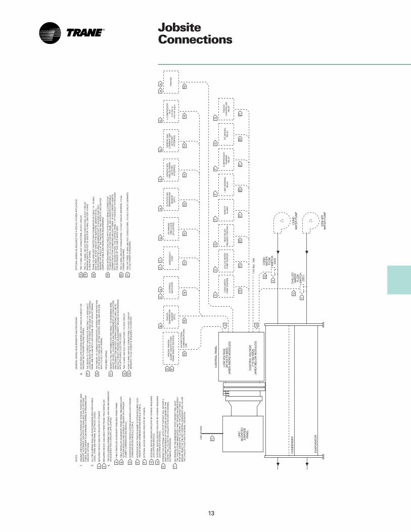
TypicalWiringDiagrams
Model RTHB Chillers with Unit Mounted Starters

17
TypicalWiringDiagrams

18
MechanicalSpecifications
GeneralExposed metal surfaces are paintedwith an air-dry beige primer-finisherprior to shipment. Each unit ships with afull operating charge of refrigerant andoil. (Separable shell units may beshipped with or without refrigerant. Seenote under options section.) Moldedneoprene isolation pads are supplied forplacement under all support points.Start-up and operator instruction byfactory trained service personnel isincluded.
Compressor-MotorSemihermetic, direct-drive, 3600 rpm,rotary compressor with: capacitycontrol slide valve, integral single-stageeconomizer, oil sump heater anddifferential pressure refrigerant oil flowsystem. Four pressure lubricated rollingelement bearing groups support therotating assembly.
Motor is a liquid refrigerant cooled,hermetically sealed, two-pole, squirrelcage induction motor.
Evaporator-CondenserShells are carbon steel plate.Evaporator and condenser aredesigned, tested and stamped inaccordance with ASME Code forrefrigerant side working pressure of300 psig.
All tube sheets are carbon steel.Evaporator and condenser tubes areindividually replaceable. Standard tubesare externally finned, internallyenhanced seamless copper with landsat all tube sheets. Evaporator tubes are1” diameter. Condenser tubes are 3/4”diameter. Tubes are mechanicallyexpanded into tube sheets. Condensertubes are mechanically fastened to tubesupports. Condenser baffle preventsdirect impingement of compressordischarge gas upon the tubes.
All water pass arrangements areavailable in either flat-faced flange(150 or 300 psig waterside) orcondenser marine configuration withgrooved connections (300 psigwaterside). All connections may beeither right or left handed. Waterside ishydrostatically tested at 11/2 timesdesign working pressure, but not lessthan 225 psig.
Refrigerant CircuitA multiple orifice control systemconsisting of an electronically controlledexpansion valve and a fixed orifice,maintains proper refrigerant flow.
Control PanelFactory mounted microprocessor-based control panel. Automaticshutdown protection with manual resetis provided for low evaporatorrefrigerant temperature and pressure,high condenser refrigerant pressure,loss of condenser water flow, highmotor temperature, low oil flow, motorcurrent overload, phase reversal, phaseloss, and severe phase imbalance.Automatic shutdown protection withautomatic reset when condition iscorrected is provided for loss of chilledwater flow, high compressor dischargetemperature, under/over voltage, andmomentary power loss.
Sentinel™ Charge Monitoring Systemprovides early detection and warning ofrefrigerant loss.
Microprocessor based chilled waterreset based on return water is standard.
The unit control module (UCM) utilizingthe Adaptive Control™ microprocessorautomatically takes action to preventunit shutdown due to abnormaloperating conditions associated withlow evaporator refrigeranttemperature, high condensingtemperature, and motor currentoverload. If the abnormal operatingcondition continues and the protectivelimit is reached, the machine will be shutdown.
Clear Language Display Panel (UCM)Factory mounted to the door of thecontrol panel, the operator interface hasa 16 button keypad for operator inputand a two line by 40 character displayscreen. A chiller report, refrigerantreport, compressor report, an operatorconfigurable custom report, operatorsettings, service settings, service tests,and diagnostics may be accessed bypressing the appropriate button. Alldiagnostics and messages aredisplayed in “clear language.”
StarterNEMA 1 enclosure with top powerwiring access and three-phase solid-state overload protection. Starters areavailable in Wye-Delta, solid-state andacross-the-line configurations. Factoryinstalled and wired 1KVA control powertransformer provides all unit controlpower (120 volt secondary). Optionalstarter features include: Circuit breakersand mechanical non-fused disconnects.
OPTIONS:Insulation: All low temperature surfacesare covered with 3/4 inch Armaflex II orequal (k = 0.28), including theevaporator, water boxes andeconomizer lines.
Refrigerant Isolation Valve: Providemeans of isolating refrigerant charge inthe condenser during servicing.
Communications: Tracer®
communications are available forTracer) or Tracer Summit (Genericbuilding automation systemcommunications requires optionsmodule.)
Options Module: Accepts genericBuilding Automation System inputs forcurrent limit setpoint and chilled watersetpoint via 2-10 VDC or 4-20 mA.Outputs a 2-10 VDC or 4-20 mA signalto Generic BAS to monitor compressor% RLA. Outputs a binary signal toGeneric BAS for use with condenserlimit control. Allows remote enable/disable of ice making operation. (Icemaking requires options module.)
Separable Shells: Allow chillerdisassembly into individual componentsfor tight installation requirements.(Isolation valves must be orderedseparately if refrigerant is required toship with unit.)
Printer Interface Module: Allows aprinter to be directly connected to theUCP2 via an RS-232 port.
Under/over Voltage Protection: Voltsdisplay on micro.
Condenser Marine Water Boxes: Alloweasy access for tube cleaning.
Condenser Tubes: Smooth bore copper,smooth bore 90/10, cupro-nickel.
Icemaking Controls: Icemaking thermalstorage can be utilized at night forreduced peak electrical demand.(Requires Options Module.)
Chilled water reset based on outdoor airtemperature.

19
MechanicalSpecifications
OPTIONS:
InsulationAll low temperature surfaces arecovered with 3/4-inch Armaflex II orequal (K = 0.28), including theevaporator, water boxes, andeconomizer lines.
Smooth Bore Condenser TubesSmooth bore copper tubes areavailable for high fouling waterapplications. Smooth bore condensertubes are 3/4” diameter and are .035WOF.
Cupro-Nickel Tubes (Condenser Only)Cupro-nickel tubes (condenser only)are available for special applicationson standard ship cycles. 90/10 cupro-nickel tubes are 3/4” diameter and.035 WOF.
Condenser Marine Water BoxesAllows for easy cleaning andmaintenance of both the evaporatorand condenser tubes by providing aneasy access without removal of waterpiping.
Standard Ice MakingControls and safeties to allowoperation with brine temperaturesgreater than or equal to 20 F. Includesdual setpoints for ice makingcapability and daytime comfortcooling. A typical application wouldinclude ice storage system withdaytime chiller operation above 40 F.(Requires Options Module.)
Separable ShellsThis option gives the installer theflexibility of taking apart the unit,reducing the overall weight and size,and making installation much easier.Units ship assembled, with or withoutrefrigerant. Units ordered withoutrefrigerant isolation valve option willbe shipped less refrigerant.
Options ModuleAccepts generic Building AutomationSystem inputs for current limit setpointand chilled water setpoint via 2-10 VDCor 4-20 mA. Outputs a 2-10 VDC or 4-20mA signal to Generic BAS to monitorcompressor % RLA. Outputs a binarysignal to Generic BAS for use withcondenser limit control. Allows remoteenable/disable of ice making operation.(Ice making requires options module.)
CommunicationsTracer® communications are availablefor Tracer or Tracer Summit. (GenericBuilding Automation Systemcommunications requires OptionsModule.)

Library Product Literature
Product Section Refrigeration
Product Rotary Liquid Chillers
Model 000
Literature Type Data Sales Catalog
Sequence 1
Date November 1999
File No. PL-RF-RLC-000-DS-1-1199
Supersedes RLC-DS-1 294
Ordering No. RLC-DS-1
Since The Trane Company has a policy of continuousproduct improvement, it reserves the right to changedesign and specification without notice.
The Trane Company3600 Pammel Creek RoadLa Crosse, WI 54601-7599www.trane.comAn American Standard Company