Series OV-1000 Omni-Valve - Hydro Instruments pages/OV-1000...Hydro Instruments Series OV-1000...
31
Series OV-1000 Omni-Valve Instruction Manual OV-1000 Rev. 2/1/19 The information contained in this manual was current at the time of printing. The most current versions of all Hydro Instruments manuals can be found on our website: www.hydroinstruments.com I I I I I In n n n n n n n n n n n n n n ns s s st t tr r r ru u u uc c c ct ti io o on n M M Ma a an nu u u u ua a a a a a a a a a a a a al l l l 1
Transcript of Series OV-1000 Omni-Valve - Hydro Instruments pages/OV-1000...Hydro Instruments Series OV-1000...
Series OV-1000Omni-Valve
Instruction Manual
OV-1000 Rev. 2/1/19
The information contained in this manual was current at the time of printing. The most current versions of all Hydro Instruments manuals can be found on our website: www.hydroinstruments.com
IIIIIInnnnnnnnnnnnnnnnsssstttrrrruuuuccccttiiooonn MMMaaannuuuuuaaaaaaaaaaaaaallll
1

Hydro InstrumentsSeries OV-1000 Omni-Valve
Table of Contents
I. Functions, Capabilities, and Construction ........................................................................3 1. Safety Precautions 2. Function of the OV-1000 3. Physical Installation 4. Chemical Types and Ranges 5. Physical Design 6. Electrical Power, Inputs & Outputs 7. Alarm Conditions & Acknowledgement 8. Dip Switches
II. Control Methods ...............................................................................................................7 1. Flow Pacing (Proportional) 2. Residual (Set Point) 3. Compound Loop (PID) 4. Dual Input Feed Forward 5. Step Feed 6. Dual Set Point
III. User Interface ..................................................................................................................15
IV. Motion Control, Valve, and 10 Point Linearization ........................................................15
V. Operation Mode Screens .................................................................................................17
VI. Confi guration Mode Screens ...........................................................................................18
VII. Advanced Calibration Mode Screens ..............................................................................22 1. Purge Feature (for liquid feed systems) 2. Dosage Method Selection 3. Flow Stop 4. External Duty/Standby and Auto/Manual control options 5. Modbus Communication
VIII. Troubleshooting and Maintenance ..................................................................................25 1. Factory Default 2. Service
Figures: 1. Installation Drawing .....................................................................................................3 2. Omni-Valve Construction .............................................................................................4 3. Omni-Valve Circuit Board ............................................................................................6 4-9: Control Schemes ................................................................................................. 8-14 10-12: Valve Linearization ....................................................................................... 15-16 13-15: Flowcharts for Screens ........................................................................... 17-18, 22 Exploded Views and Bills of Material ...................................................................... 26-31
2

I. FUNCTIONS, CAPABILITIES, AND CONSTRUCTION
1. SAFETY PRECAUTIONS
GENERAL: Be sure to follow all applicable and prudent safety precautions when working with chemicals and electrical equipment.
ELECTRICAL: The circuit board and incoming A/C power line do include electrical shock risk. Take care to avoid electrical shocks and do not touch any part of the circuit board or A/C power line unless you are certain that A/C power has been disconnected from the system.
CHECK FOR DAMAGE: Before removing the product from the shipping packaging, carefully check the equipment for damage. If any product is found damaged, do not put it into operation or install it. Contact Hydro Instruments to discuss repair or replacement of the damaged equipment.
2. Function of the OV-1000: The OV-1000 Omni-Valve is designed to automatically control chemical feed rate based on one or more electrical input signals. Figure 1 shows an example installation drawing.
3. Physical Installation: The Omni-Valve must be mounted in the chemical feed line downstream from a chemical fl ow meter and upstream from the feed point (i.e. ejector, vacuum pump or check valve dif-fuser). Consider Figure 1 above.
NOTE: If the automatic valve is being used for liquid chemical feed such as sodium hypochlorite, having the chemical physically higher than the valve will create a hydrostatic pressure which could cause failure of the valves internal seals.
4. Chemical Types and Ranges: For gaseous chemical feed applications, the OV-1000 Omni-Valve is most commonly used for chlorine, sulfur dioxide, ammonia, and carbon dioxide. For liquid chemical feed applications, the OV-1000 Omni-Valve is most commonly used for sodium hypochlorite, hydro-chloric acid, sodium bisulfi te, sodium bisulfate, sodium chlorite, and aqueous ammonia solutions. Consult Hydro Instruments for usage in other chemical applications and for available feed rate ranges.
FIGURE 1 – SYSTEM EXAMPLE: WALL PANEL OMNI-VALVE WITH RESIDUAL ANALYZER
3

FIGURE 2 – OV-1000 CONTROLLER ELECTRONICS
Date: 2019-02-01-v1 Dwg. No. OV-1000-CONTROLLEROV-1000 CONTROLLER
ELECTRONICS
OV-1000Printed Circuit BoardModbus
Connections
Micro SDCard Slot
Power SupplyBoard
Stepper Motor
Motor Wires
Motor Switch
OV-1000Mechanical
Subassembly
AC PowerTerminal Block
ToggleSwitch
Home Switch Assemblywith Threaded Adapter
4
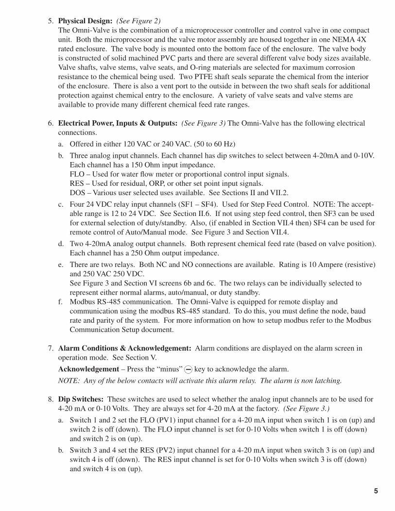
5. Physical Design: (See Figure 2) The Omni-Valve is the combination of a microprocessor controller and control valve in one compact
unit. Both the microprocessor and the valve motor assembly are housed together in one NEMA 4X rated enclosure. The valve body is mounted onto the bottom face of the enclosure. The valve body is constructed of solid machined PVC parts and there are several different valve body sizes available. Valve shafts, valve stems, valve seats, and O-ring materials are selected for maximum corrosion resistance to the chemical being used. Two PTFE shaft seals separate the chemical from the interior of the enclosure. There is also a vent port to the outside in between the two shaft seals for additional protection against chemical entry to the enclosure. A variety of valve seats and valve stems are available to provide many different chemical feed rate ranges.
6. Electrical Power, Inputs & Outputs: (See Figure 3) The Omni-Valve has the following electrical connections.
a. Offered in either 120 VAC or 240 VAC. (50 to 60 Hz)
b. Three analog input channels. Each channel has dip switches to select between 4-20mA and 0-10V. Each channel has a 150 Ohm input impedance.
FLO – Used for water fl ow meter or proportional control input signals. RES – Used for residual, ORP, or other set point input signals. DOS – Various user selected uses available. See Sections II and VII.2.
c. Four 24 VDC relay input channels (SF1 – SF4). Used for Step Feed Control. NOTE: The accept-able range is 12 to 24 VDC. See Section II.6. If not using step feed control, then SF3 can be used for external selection of duty/standby. Also, (if enabled in Section VII.4 then) SF4 can be used for remote control of Auto/Manual mode. See Figure 3 and Section VII.4.
d. Two 4-20mA analog output channels. Both represent chemical feed rate (based on valve position). Each channel has a 250 Ohm output impedance.
e. There are two relays. Both NC and NO connections are available. Rating is 10 Ampere (resistive) and 250 VAC 250 VDC.
See Figure 3 and Section VI screens 6b and 6c. The two relays can be individually selected to represent either normal alarms, auto/manual, or duty standby.
f. Modbus RS-485 communication. The Omni-Valve is equipped for remote display and communication using the modbus RS-485 standard. To do this, you must defi ne the node, baud rate and parity of the system. For more information on how to setup modbus refer to the Modbus Communication Setup document.
7. Alarm Conditions & Acknowledgement: Alarm conditions are displayed on the alarm screen in operation mode. See Section V.
Acknowledgement – Press the “minus” key to acknowledge the alarm.
NOTE: Any of the below contacts will activate this alarm relay. The alarm is non latching.
8. Dip Switches: These switches are used to select whether the analog input channels are to be used for 4-20 mA or 0-10 Volts. They are always set for 4-20 mA at the factory. (See Figure 3.)
a. Switch 1 and 2 set the FLO (PV1) input channel for a 4-20 mA input when switch 1 is on (up) and switch 2 is off (down). The FLO input channel is set for 0-10 Volts when switch 1 is off (down) and switch 2 is on (up).
b. Switch 3 and 4 set the RES (PV2) input channel for a 4-20 mA input when switch 3 is on (up) and switch 4 is off (down). The RES input channel is set for 0-10 Volts when switch 3 is off (down) and switch 4 is on (up).
5

FIGURE 3 – PINOUT DIAGRAM FOR OV-1000 CIRCUIT BOARD
Dat
e: D
ecem
ber
2016
Dw
g. N
o. O
V-P
CB
-2O
MN
I-V
AL
VE
CIR
CU
IT B
OA
RD
Rib
bon
Cab
leto
Dis
play
Mic
ro S
DC
ard
Rea
der
Pin
Con
nect
orto
Ste
pper
Mot
or
+
–12
VD
CP
ower
V+ A B V-
MSW
GN
D N
O1
CO
1 N
C1
NO
2 C
O2
NC
2
Out
put r
elay
ala
rms
or A
uto/
Man
lor
Dut
y/S
tand
byM
otor
Sw
itch
Dip
sw
itche
s fo
r F
LO,
RE
S, a
nd G
ND
inpu
ts
DO
S
GN
D
RE
S
GN
D
FLO
GN
D
AO
1
GN
D
AO
2
GN
D
SF
1+S
F1-
SF
2+S
F2-
SF
3+S
F3-
SF
4+S
F4-
Ana
log
Inpu
ts
Ana
log
Out
puts
12V
DC
to 2
4VD
C(s
tep
feed
inpu
ts)
SF
3 (S
ee S
ectio
n V
II.4.
a)E
xter
nal D
uty/
Sta
ndby
Con
trol
SF
4 (S
ee S
ectio
n V
II.4.
b)E
xter
nal A
UTO
/M
AN
L C
ontr
ol
Mod
bus
Term
inal
s
6

c. Switch 5 and 6 set the DOS (PV3) input channel for a 4-20 mA input when switch 5 is on (up) and switch 6 is off (down). The DOS input channel is set for 0-10 Volts when switch 5 is off (down) and switch 6 is on (up).
Control Mode Alarm Condition Description Action
Flow Pacing Flow Signal Loss PV1 Signal below 4 mA Valve Close or Hold Position**
Flow Pacing Low Flow PV1 Signal below set point* None
Residual/ORP Res/ORP Signal Loss PV2 Signal below 4 mA Valve Close or Hold Position**
Residual/ORP Low Residual PV2 Signal below set point*** None
Residual/ORP High Residual PV2 Signal above set point*** NoneCompound Loopor Feed Forward
Flow Signal Loss PV1 Signal below 4 mA Switch to Residual/ORP Condn 1
Compound Loopor Feed Forward
Low Flow PV1 Signal below set point* None
Compound Loopor Feed Forward
Res/ORP Signal Loss PV2 Signal below 4 mA Switch to Flow Pacing Control
Compound Loopor Feed Forward
Low Set Point PV2 Signal below set point*** None
Compound Loopor Feed Forward
High Set Point PV2 Signal above set point*** None
II. CONTROL METHODS
The OV-1000 Omni-Valve offers the following control methods. The control method is selected in the Confi guration Mode (See Section VI).
1. Flow Pacing (Proportional): Figure 4 below shows an example installation.
a. Application: This control method is suitable when water quality is consistent, but water fl ow rate is variable.
b. Control Signals: In this case, a 4-20mA (or 0-10V) signal from the water fl ow meter (measuring water fl ow just upstream from the injection point) is input to the FLO/GND input channel of the OV-1000.NOTE: If desired, a proportional 4-20mA control signal from any PLC can be used in the same fashion.
c. Control Concept: Chemical feed rate is adjusted in direct proportion to the input signal with no delay.
d. Initial Settings: In the Confi guration Mode (Section VI), the fl ow settings will need to be adjusted to match the water fl ow meter being used.
e. User Interaction: During operation, the user only needs to adjust the dosage setting to adjust the ratio of chemical feed rate to water fl ow rate. Optionally the dosage can be remotely adjusted by means of the DOS/GND input channel. See Section VII.2.
7

2. Residual/ORP (Set Point): Figure 5 below shows an example installation.
a. Application: This control method is suitable when water quality is variable, but water fl ow rate is constant or relatively steady.
b. Control Signals: In this case, a 4-20mA (or 0-10V) signal from the residual analyzer (measuring residual just downstream from the injection point) is input to the RES/GND input channel of the OV-1000.
c. Control Concept: Chemical feed rate is periodically adjusted in order to keep the resultant chlorine residual (or ORP or similar chemical concentration) on the user determined set point.
i. Sample point selection is very important. The sample point must be at least 10 x pipe diameter downstream (to ensure complete mixing prior to sampling) and the lag time (“lag time” = the time it takes the chemical to travel from the Omni-Valve to the residual analyzer) should be minimized to optimize control (ideally limit this time to less than 5 minutes).
ii. The Omni-Valve will only adjust chemical feed rate once every lag time. Each time the lag time expires, the Omni-Valve will compare the residual reading with the residual set point and if the residual reading is not on set point, then the chemical feed rate will be adjusted to bring the residual back toward the set point.
d. Initial Settings: In the Confi guration Mode (Section VI): i. The residual settings will need to be adjusted to match the residual analyzer that is being used. ii. The lag time will need to be measured on site and then entered. iii. Dead Band: The Dead Band allows for an adjustable range around the set point that is consid-
ered acceptable for residual. As long as the residual reading is within this range (+ or -) from the set point, then the residual is considered to be on set point.
FIGURE 4 – FLOW PACING
8

iv. Integral: The Integral “I” controls the magnitude of each chemical feed rate adjustment. The typical range is 10% < I < 30%. If the integral setting is too low, then the Omni-Valve will be too slow in making adjustments and if the integral setting is too high, then it will continually overshoot the set point (residual oscillating between too high and too low).
e. User Interaction: During operation, the user only needs to adjust the residual set point. Optionally the set point can be remotely adjusted by means of the DOS/GND input channel. See Section VII.2.
3. Compound Loop (PID): Figure 6 below shows an example installation.
a. Application: This control method is suitable when both water quality and water fl ow rate are vari-able.
b. Control Signals: In this case, two input signals are required: i. A 4-20mA (or 0-10V) signal from the water fl ow meter (measuring water fl ow just upstream
from the injection point) is input to the FLO/GND input channel of the OV-1000. ii. A 4-20mA (or 0-10V) signal from the residual analyzer (measuring residual just downstream
from the injection point) is input to the RES/GND input channel of the OV-1000.
c. Control Concept: Both Flow Pacing (Section II.1) and Residual (Section II.2) are being carried out simultaneously. Review both above Flow Pacing and the Residual Control sections.
d. Initial Settings: In the Confi guration Mode (Section VI): i. All of the settings from both Flow Pacing (Section II.1) and Residual (Section II.2). ii. Flow Stop: If the water fl ow completely stops, then the Omni-Valve will continue to adjust
based on residual. This can be avoided by setting a lower limit on the fl ow signal below which the automatic control will automatically turn off. See section VII.3.
iii. Variable lag time: Since the lag time is often approximately inversely proportional to the water fl ow rate (meaning as the water fl ows faster, the lag time will decrease), Compound Loop Control method allows for a variable lag time. If variable lag time is to be used, then it needs to be enabled, the lag time, the water fl ow rate at that entered lag time, and a maximum allowable value for lag time must all be entered in the Confi guration Mode.
FIGURE 5 – RESIDUAL (SET POINT)
9

FIGURE 6 – COMPOUND LOOP (PID)
e. User Interaction: During operation, the user will adjust both the dosage (Section II.1) and the residual set point (Section II.2). Optionally the dosage or the set point can be remotely adjusted by means of the DOS/GND input channel. See section VII.2.
4. Dual Input Feed Forward: Figure 7 below shows an example installation.
a. Application: Chemical feed rate is controlled in proportion to the mass fl ow rate of a second chemical that is already in the water stream. This is most commonly used in de-chlorination and chloramination applications. In these applications, chemical is being injected in order to react with another chemical that is already present in the water stream.
b. Control Signals: In this case, two input signals are required: i. A 4-20mA (or 0-10V) signal from the water fl ow meter (measuring water fl ow just upstream
from the injection point) is input to the FLO/GND input channel of the OV-1000. ii. A 4-20mA (or 0-10V) signal from the residual analyzer (measuring residual of the target
chemical just upstream from the injection point) is input to the RES/GND input channel of the OV-1000.
c. Control Concept: This method requires a water fl ow signal and a residual signal for the other chemical that is already present in the water stream. The Omni-Valve uses these two signals to calculate the mass fl ow rate of the other chemical in the water stream. The Omni-Valve will then control chemical feed rate in proportion to this mass fl ow rate.
d. Initial Settings: In the Confi guration Mode (Section VI): i. All of the settings from both Flow Pacing (Section II.1). ii. Residual (Section II.2) signal reading parameters only (no Dead Band, Lag Time, or Integral).
e. User Interaction: During operation, the user only needs to adjust the dosage setting to adjust the ratio of chemical feed rate to the other chemical mass fl ow rate. Optionally the dosage can be re-motely adjusted by means of the DOS/GND input channel. See Section VII.2.
10

5. Step Feed: Figure 8 below shows an example installation.
a. Application: This control method is useful for systems injecting chemical into a line downstream of one to four supply pumps when each of the pumps has a fi xed fl ow rate (up to four wells or other pumps feeding one line).
b. Control Signals: In this case, there will be up to four 24VDC dry contact input signals. These signals are used to indicate whether each pump is on or off. The signals are to be connected to the SF1+/SF1-, SF2+/SF2-, SF3+/SF3-, and SF4+/SF4- input channels. NOTE: The acceptable range is 12 to 24 VDC.
c. Control Concept: Up to four relay contact signals are input to the Omni-Valve. Each relay can be allotted a fi xed chemical feed rate. The Omni-Valve chemical feed rate is then set to the sum of the feed rates allotted to the relays that are active.
d. Initial Settings: In the Confi guration Mode (Section VI), the chemical feed rate for each input channel must be entered.
e. User Interaction: During operation, no user interaction is required.
6. Dual Set Point: Figure 9 shows an example installation.
a. Application: This control method is designed for applications injecting chemical upstream of a contact chamber. In such cases, a residual analyzer nearby the injection point can be used to control chemical injection. This allows for automatic control of residual at the injection point. However, control of the residual at the outlet of the contact chamber is the ultimate goal. If water quality remains constant then there will be a fi xed drop in residual between the injection point and the contact chamber outlet. However, water quality variations will cause this residual drop to be variable. This control method is used to overcome this problem and allow for fully automated chemical feed rate control in such situations.
b. Control Signals: In this case, two input signals are required: NOTE: Refer to Section VII.2.d. for information on how to activate the DOS/GND input. i. A 4-20mA (or 0-10V) signal from the residual analyzer (measuring residual just downstream
from the injection point) is input to the RES/GND input channel of the OV-1000. ii. A 4-20mA (or 0-10V) signal from the residual analyzer (measuring residual at the contact
chamber outlet) is input to the DOS/GND input channel of the OV-1000.
FIGURE 7 – DUAL INPUT FEED FORWARD
11

c. Control Concept: The OV-1000 can be operated in either Residual Control or Compound Loop Control using the Dual Set Point control method. In either case, the chemical feed rate control will be carried out using the residual signal coming into RES/GND (as described in Sections II.2 and II.3).
i. As in the above Section II.2 and II.3, there will be a lag time for the injection point analyzer (RES/GND channel). We will call this lag time “LT1”. As described in Sections II.2 and II.3, this lag time should be limited to 5 minutes or less.
ii. There will also be a lag time for the residual analyzer (DOS/GND channel) that is located at the outlet of the contact chamber. This lag time (call it LT2) should be set as the delay from feed rate changes to registering on the DOS/GND analyzer plus 3 to 4 times LT1. For example, if LT1 = 100 seconds and the delay for the DOS/GND analyzer is 1800 seconds, then set LT2 = 1,800 + 3 x 100 = 2,100 seconds. LT2 has a range up to 9999 seconds (over 2 hours & 46 minutes).
iii. In this Dual Set Point control method, there is a user adjustable set point for each of the analyzers. We will call them SP2 (RES/GND channel) and SP3 (DOS/GND channel).
iv. The Dual Set Point control method concept is that each time the LT2 lag time expires, the Omni-Valve will compare the residual reading (on DOS/GND channel) with its SP3 set point. If this residual reading is not on set point, then the Omni-Valve will then automatically adjust the SP2 accordingly.
d. Initial Settings: In the Confi guration Mode: i. The residual settings will need to be adjusted to match each of the residual analyzers. ii. Both of the lag times (LT1 and LT2) will need to be measured on site and entered. iii. “PV3 Integral” is used to adjust the magnitude of each SP2 adjustment. (1% < PV2 Integral <
100%). The default value is 50%. See section VI, screen 8c. iv. Some of the settings made for the “Res” input will be used for “Res2”. Those include: units,
decimal position, fi lter time, and dead band.
e. User Interaction: If in Residual Control Mode, then the user will be able to adjust both of the residual set points (SP2 and SP3). If in Compound Loop Control Mode, then the user will also adjust the dosage.
12

FIGURE 8 – STEP FEED
13
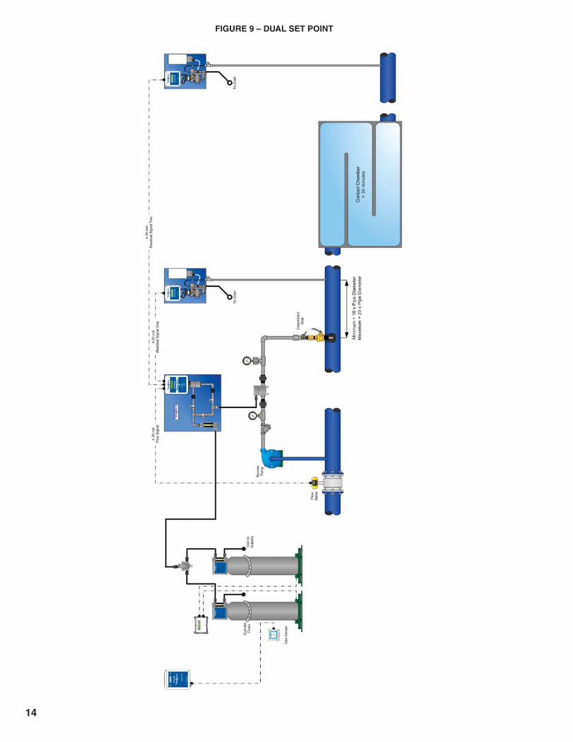
FIGURE 9 – DUAL SET POINT
14
III. USER INTERFACE
The Omni-Valve operation and adjustments are carried out through the following interface features.
1. Display: Two line, 20 character per line, alphanumeric LCD. Keypad Operation – The keypad is used in all three modes of the OV-1000. Generally the keys are
used as outlined here below. However, detailed instructions will follow.
a. & keys – These keys are used to cycle through the various display screens. These keys will be referred to as “up arrow” and “down arrow”.
b. & keys – These keys are generally used to adjust settings and values within the screen being displayed. These keys will be referred to as “plus” and “minus”. Additionally, the plus key is used as Enter for blinking options on the Confi guration modes SETUP screen or to Enter yes/no selections while in the Advanced Calibration mode.
2. On the main operating screen you can manually switch between automatic (AUTO) and manual (MANL) modes of the Omni-Valve by pressing the key. The valve can be changed from AUTO to MANL remotely as well, see section VII.4 for details.
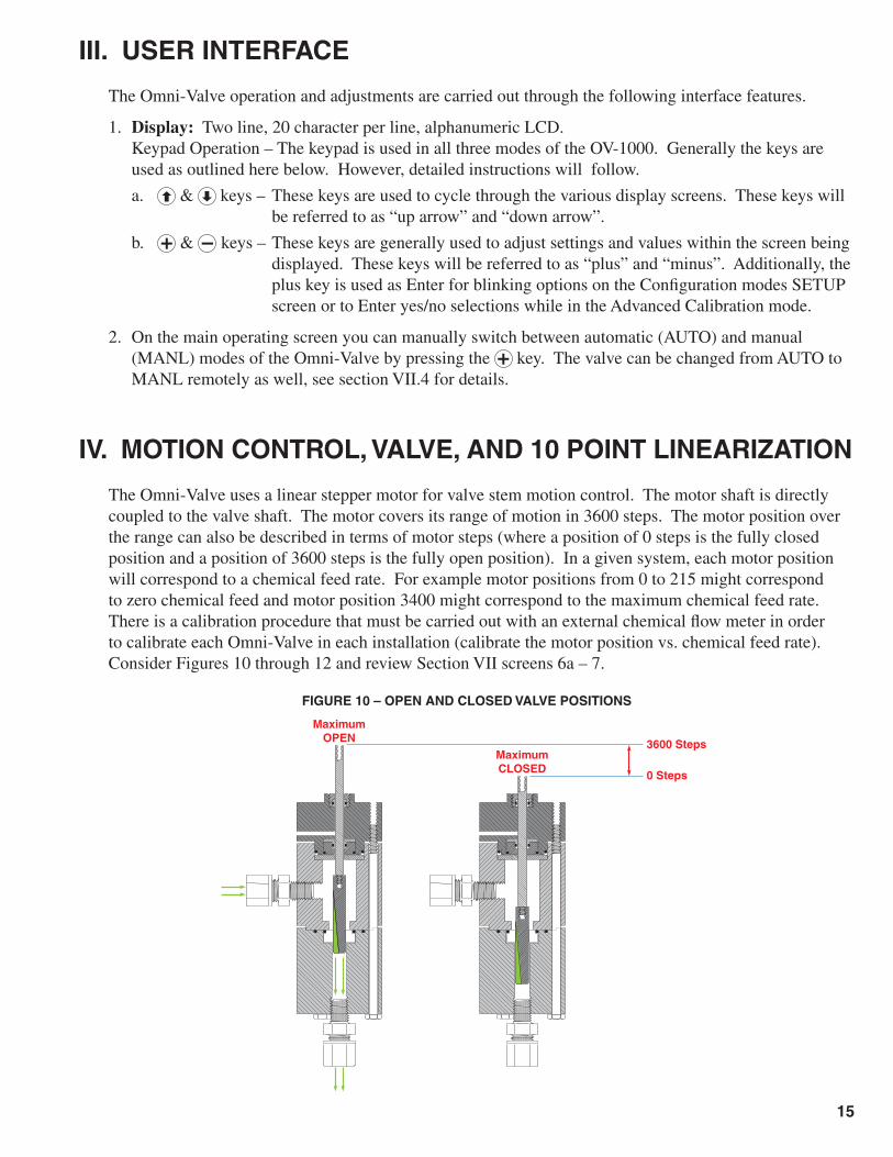
IV. MOTION CONTROL, VALVE, AND 10 POINT LINEARIZATION
The Omni-Valve uses a linear stepper motor for valve stem motion control. The motor shaft is directly coupled to the valve shaft. The motor covers its range of motion in 3600 steps. The motor position over the range can also be described in terms of motor steps (where a position of 0 steps is the fully closed position and a position of 3600 steps is the fully open position). In a given system, each motor position will correspond to a chemical feed rate. For example motor positions from 0 to 215 might correspond to zero chemical feed and motor position 3400 might correspond to the maximum chemical feed rate. There is a calibration procedure that must be carried out with an external chemical fl ow meter in order to calibrate each Omni-Valve in each installation (calibrate the motor position vs. chemical feed rate). Consider Figures 10 through 12 and review Section VII screens 6a – 7.
FIGURE 10 – OPEN AND CLOSED VALVE POSITIONS
MaximumOPEN 3600 Steps
0 Steps
MaximumCLOSED
15

Maximum OPEN3600 Steps
0 StepsMaximum CLOSED
Maximum OPEN3600 Steps
0 StepsMaximum CLOSED
FIGURE 11 – EXAMPLE FEED RATE AND MOTOR POSITION CHART
FeedRate%
FeedRatekg/hr
MotorPosition
Steps
0% 0 288
5% 0.5 549
10% 1 711
15% 1.5 810
25% 2.5 1080
35% 3.5 1350
50% 5 1818
70% 7 2340
85% 8.5 2826
100% 10 3276
FIGURE 12 – TEN POINT CALIBRATION CHART
0 1 2 3 4 5 6 7 8 9 10
Feed Rate (kg/hr)
Mot
or P
ositi
on (
step
s)
3600
3240
2880
2520
2160
1800
1440
1080
720
360
0
10 Point Calibration
16

V. OPERATION MODE
The operation mode is a set of screens that display the main operating parameters based on the control type selected in the confi guration mode. The dosage, residual/ORP set point, and chemical feed rate can be adjusted from these screens.
NOTES: 1. On the fi rst screen on each mode, use the key to switch between AUTO and MANL. 2. “Set PO1 (valve)” screens only appear if set to MANL mode. From this screen the user can set the
Omni-Valve feed rate manually using the and keys. 3. Use the and keys to adjust Dosage, Set Points, Valve Position (PO1) etc…
Dosage: This value is a multiplication factor for the calculated chemical feed rate. It can be set to fi ne tune the feed rate when in Flow Pacing, Compound Loop, Feed Forward or Dual Set Point control.
Flow Pacing Example: Valve Output = [(Actual Flow/Flow Full Scale) * Valve Full Scale] * Dosage
Setpoint: The set point is the residual/ORP/pH value that the Omni-Valve will try to maintain.
This screen is only visible in MANL mode.From this screen the user can set the
Omni-Valve feed rate manually.
“Compound Loop”AUTO / MANL
AUTO RES -1.24 PPM
¹¹¹¹ PO1 0 PPD
AUTO FLO -24.8 %
¹¹¹¹ PO1 0 PPD
Set Point Res/ORP
2.00 PPM
Set DOSAGE
1.00
Set PO1(Valve)
¹¹¹¹ 0 PPD
Alarm Status
Normal
Enter Password
1000
AUTO RES -1.24 PPM
¹¹¹¹ PO1 0 PPD
Set Point Res/ORP
2.00 PPM
“Residual/ORP”AUTO / MANL
AUTO Feed Rate
¹¹¹¹ PO1 0 PPD
“Step Feed”AUTO / MANL
AUTO RES -1.24 PPM
¹¹¹¹ PO1 0.0KG/H
AUTO FLO -24.9 %
¹¹¹¹ PO1 0.0KG/H
“Dual Input Feed Fwd”AUTO / MANL
Set DOSAGE
1.00
AUTO
MANL
increase/decrease
increase/decrease
increase/decrease
increase/decrease
AUTO FLO -24.8 %
¹¹¹¹ PO1 0 PPD
Set DOSAGE
1.00
“Flow Pacing”AUTO / MANL
increase/decrease
FIGURE 13 – OPERATION MODE SCREENS
17

VI. CONFIGURATION MODE
Step Feed Input 1
PO1 25 PPD
STEP
Step Feed Input 2
PO1 50 PPD
Step Feed Input 3
PO1 75 PPD
Step Feed Input 4
PO1 100 PPD
00.00
0.000
00000
000.0
%
GPM
MGD
LPM
MLD
GPD
M3/H
LPH
Flow Input Name
FLO
FLO
PV1
H2O
PRO
Input Signal Loss
Maintain Valve Posn
Flow Input Units
%
Flow Decimal Posn
000.0
000.0
00.00
0.000
00000
Flow Full Scale
100.0 %
Flow Threshold
0.0 %
Flow Filter Time
10 secs
Flow Low Set
0.0 %
Maintain Valve Posn
Close Valve
PPM
MG/L
mV
pH
NTU
%
Res Input Name
RES
RES
ORP
pH
Ch1
SCM
TDS
DO
CON
TUR
PV2
Input Signal Loss
Maintain Valve Posn
Res Units
PPM
Res Decimal Posn
00.00
Res Full Scale
5.00 PPM
Res Minimum Value
0.00 PPM
Res Filter Time
10 secs
Maintain Valve Posn
Close Valve
FLO
RES
Res Low Set
0.00 PPM
Res High Set
5.00 PPM
Res Dead Band
0.10 PPM
Res Integral Value
20.0 %
Output Units
PPD
PPD
GR/H
KG/H
GPH
GPM
GPD
LPM
LPH
%
00000
000.0
00.00
0.000
Output Decimal Posn
00000
OUT
Alarm Delay Time
10 secs
Output Relay 1 Usage
Normal Alarms
ALM
Begin Adv Cal Mode?
No Yes
ADCAL
Ref
er to
Sec
tion
VII a
nd
Figu
re V
II fo
r det
aile
d “A
dvan
ced
Cal
ibra
tion
Mod
e”
inst
ruct
ions
.
Output Relay 2 Usage
Normal Alarms
Normal Alarms
Auto(Off)/Manl(On)
Duty(Off)/Stdby(On)
PO1 Gas Flow Alarm
Cl2
SO2
Output Full Scale
1000 PPD
Out Gas Feed Type
Cl2
10% to 100%
PO1 GFM Full Scale
1000 PPD
PO1 GFM Alarm Error
10%
Thes
e sc
reen
s fo
r set
ting
Gas
Flo
w M
eter
Ful
l Sca
le a
nd
Gas
Flo
w M
eter
Ala
rm E
rror
will
be v
isib
le w
hen
D =
4(D
can
be
seen
and
set
with
inAd
v C
al M
ode
hidd
en s
cree
n)
SETUP: FLO RES STEP
OUT ALM ADCAL
Control Type
Flow Pacing
Flow Pacing
Residual/ORP
Compound Loop
Step Feed
Dual Input Feed Fwd
Lag Time Mode
2 Point Var Lag Time
FA1=50% TA1=60s
FA2=75% TA2=40s
A=0.0
F= 0
B=0.0
T=60
Maximum Lag Time
1800 secs
Lag Time Mode
1 Point Var Lag Time
Flow at Variable Lag
30.0%
Res Lag Time
60 secs
Maximum Lag Time
1800 secs
Lag Time Mode
Fixed Lag Time
Res Lag Time
60 secs
Res Reset Value
0.0 %
FIGURE 14 – CONFIGURATION SCREENS
18

The confi guration mode of the Omni-Valve allows the user to adjust key parameters to the control type selected. As a general reference all settings on the analyzer should match the setting on the incoming signals. The following is a brief description of what each setting does. Note that based on the type of control method selected all the screens may not appear.
Enter Password: To enter the confi guration mode, a password must be entered. Hydro Instruments’ has set this password equal to “1000”.
Control Type: This screen allows the user to select the control type desired. Refer to section II for the optimal control type desired.
FLO – Flow These screens are used for setting up the water fl ow signal and control parameters.
Flow Input name: This screen allows the user to enter a name for the fl ow signal. Options include: PV1, H2O, PRO, FLO.
Input Signal loss: This screen will dictate to the omni-valve what to do when an input signal (FLO, RES, DOS) has be lost. The omni-valve can be selected to either maintain its current position, or close the valve and shut off feed until the signal is restored.
Flow Input Units: This screen allows the user to set the fl ow units on the omni-valve. Options included: %, GPM, MGD, LPM, MLD, GPD, M3/H, LPH.
Flow Decimal Posn: This screen sets the decimal position of fl ow signal on the omni-valve.
Flow Full Scale: This screen sets the full scale of fl ow rate the omni valve will display. I.E. the fl ow rate when the signal input is at 20 mA (or 10 V). It is very important to match this with the full scale of the fl ow meter.
Flow Threshold: This value determines the fl ow percentage below which the fl ow signal will be ignored. This also re-scales the incoming fl ow signal. For example, with a 4-20 mA signal and a fl ow threshold of 50%, the omni-valve will remain closed at any signal below 12 mA and will begin feeding above 12 mA linearly up to 20 mA. For normal operation this value should be set at 0% so that it will feed throughout the whole 4-20 mA range.
Flow Filter Time: This value will set the time over which the omni-valve will average incoming fl ow signal.
Flow Low Set: This is used for alarm indication for when the fl ow rate has gone below the set value.
RES – Residual These screens are used for setting up the residual signal and control parameters.
Res Input name: This screen allows the user to enter a name for the residual signal. Options include: RES, ORP, pH, Ch1, PV2, SCM, TDS, DO, CON, TUR.
Res Units: This screen allows the user to enter the units for the incoming residual signal. Options include: PPM, mg/L, mV, pH, NTU, %.
Res Decimal Posn: This screen sets the decimal position of residual on the Omni-Valve.
Res Full Scale: This screen sets the full scale residual/ORP displayed on the Omni-Valve. This corresponds the 20 mA (or 10 V) output from the downstream controller.
Res Minimum Value: This screen sets the low end value of the residual/ORP signal. This would correspond to the 4 mA (or 0V) incoming signal from the downstream controller. This value is more often adjusted in ORP control type applications.
19

Res Filter Time: This value will set the time over which the omni-valve will average incoming residual/ORP signal.
Res Low Set: This is used for alarm indication for when the residual/ORP fall below the set value. Setting this value to 0 turns the alarm off.
Res High Set: This is used for alarm indication for when the residual/ORP is above the set value.
Res Dead Band: the dead band allow for an adjustable range around the set point that is considered an acceptable residual level. As long as the residual/ORP value is within +/- this value from the set point, the omni-valve will consider this level “ok” and not make any adjustments.
Res Integral Value: This value is used in the PID control calculations to make calculated adjustments back to the set point. An integral value too high will cause large swings above and below the set point and an integral value to low will take too long to reach the set point. A typical value will be between 10-30 %. Hydro Instruments’ factory sets this value at 20%.
Res Lag Time: The lag time is the time between when the omni-valve makes and adjustment and when it reads the incoming residual signal based on the adjustment. Lag times should be measured (and then entered) between when the omni-valve makes and adjustment and when that adjustment reaches the downstream instrument. This is a very important value for the most accurate and reliable control.
Res Reset Value: This value is used in compound loop control for when the fl ow signal falls below the set value the incoming residual/ORP signal will be ignored.
Variable Lag Time: This value is used in compound loop mode; to adjust the residual lag time based on changes in fl ow as a faster fl ow rate will reach the downstream instrument faster. To activate the variable lag time select yes.
Maximum Lag Time: When variable lag time is activated this is the longest time the omni-valve will wait to take a reading once an adjustment has been made.
Flow at Variable Lag: This value is the fl ow value at which the residual lag time was measured.
System Outlet Range: This screen is used to set the minimum and maximum value of a second residual/ORP analyzer. This is for dual set point control and the inputs for this analyzer should be wired into the DOS/GND line.
RES2 – Residual Outlet These screens are used for setting up the second residual signal and control parameters. These are for use
with Dual Set-Point Control only.
System Outlet Point Lag Time 2: This value sets the time between when the omni-valve makes and adjustment and when it measures the incoming signal from the DOS/GND connection based on that adjustment.
PV3 Integral Value: This value is used in the PID control calculations to make calculated adjustments back to the set point. A larger integral value will make larger feed rate changes. Setting the value too high will cause rapid swings above and below the set point and setting it too low will take too long to reach the set point. Hydro Instruments recommends this value be set at 50%.
System Outlet Lag Time Variable: This value is used in compound loop mode; to adjust the residual lag time based on changes in fl ow as a faster fl ow rate will reach the downstream instrument faster. To activate the variable lag time select yes.
20

OUT – Output These screens are used for setting up the valves chemical feed output.
Output Units: This screen allows the user to select the units or the chemical feed rate (PO1). Options include: %, PPD, g/hr, kg/hr, GPH, GPM, GPD, LPM, LPH.
Output Decimal Posn: This screen sets the decimal position of chemical feed rate on the omni-valve.
Output Full Scale: This screen sets the full scale of the chemical feed rate the omni valve will display.
Output Gas Type: This screen allows the user to select between CL2 and SO2. This is important for control types where residual control is important as the CL2 acts proportionally to the residual signal (i.e. when the value is below set point it adds more chemical) and SO2 acts inversely proportional to the residual signal (I.E. when the residual signal is above the set point it adds more chemical). Thus SO2 is most commonly selected when de-chlorinating or pH control.
STEP – Step Feed These screens are used for setting the incremental feed rates when using step feed control.
Step Feed Input 1: This value sets the percentage of full scale the omni-valve will feed when the SF1 terminal is activated.
Step Feed Input 2: This value sets the percentage of full scale the omni-valve will feed when the SF2 terminal is activated.
Step Feed Input 3: This value sets the percentage of full scale the omni-valve will feed when the SF3 terminal is activated.
Step Feed Input 4: This value sets the percentage of full scale the omni-valve will feed when the SF4 terminal is activated.*Note that if multiple pumps will be activated at once, the sum should not exceed 100%.
ALM – Alarm These screens are used for setting up additional alarm features.
Alarm Delay Time: Set the time for which a condition must be in alarm state for the alarm to activate.
Output Relay Usage: The user can independently select each of the relays to indicate one of three parameters: normal alarms, auto/manual, or duty/standby.
21

VII. ADVANCED CALIBRATION MODE
Hid
den
Scre
ens
Change Flo Zero Cal?
Yes
AO1 Cal: 4mA=
403
20mA=2001
Change Flo Span Cal?
Yes
Change Res Zero Cal?
Yes
Change Res Span Cal?
Yes
Change PV3 Zero Cal?
Yes
Change PV3 Span Cal?
Yes
AO2 Cal: 4mA=
393
20mA=1990
“Beg
in A
dv C
al M
ode?
” sc
reen
with
“No”
flas
hing
...
Confirm New Flo Zero
Cancel Change Now
Confirm New Flo Span
Cancel Change Now
Confirm New Res Zero
Cancel Change Now
Confirm New Res Span
Cancel Change Now
Confirm New PV3 Zero
Cancel Change Now
Confirm New PV3 Span
Cancel Change Now
HO
LDNo
The
num
bers
dis
play
ed a
re th
e in
puts
to th
e D
AC
.Th
e ra
nge
for e
ach
is 0
to 4
095.
Adj
ustin
g th
ese
num
bers
adj
usts
th
e 4-
20m
A ou
tput
sig
nal v
alue
.
“Beg
in A
dv C
al M
ode?
” sc
reen
with
“Yes
” fla
shin
g...
Purg Tm= 0 Wt= 99
PV1Stop=00% D=0
HO
LDYes
Select Inputs
PV1=A PV2=A PV3=A
A M
Modbus Baud= 19200
Node= 1 Data= 8/N/1
8/N/1
8/N/2
8/E/1
8/O/1
PO1
PV1
AO1 Output = PO1
AO2 Output = PO1
PO1 1000 PPD
PO1GFM Off
Enable Ext Auto/Man?
No
No
Yes
01
23
4
Modbus Baud= 19200
Node= 1 Data= 8/N/1
Modbus Baud= 19200
Node= 1 Data= 8/N/1
2400
4800
9600
19200
38400
57600
115200
250000
1 thru
255
A :
Ana
log
4-20
mA
M :
Mod
bus
RS
485
SETUP: FLO RES STEP
OUT ALM ADCAL
Control Type
Flow Pacing
Flow Pacing
Residual/ORP
Compound Loop
Step Feed
Dual Input Feed Fwd
Begin Adv Cal Mode?
No Yes
ADCAL
PO1 15% 810
¹¹¹¹¹
Auto Valve Chk Time
168 hrs (0=Off)
PO1 0% 288
¹¹
PO1 5% 549
¹¹¹
PO1 10% 711
¹¹¹¹
PO1 25% 1080
¹¹¹¹¹¹
PO1 35% 1350
¹¹¹¹¹¹¹¹
PO1 50% 1818
¹¹¹¹¹¹¹¹¹¹
PO1 70% 2340
¹¹¹¹¹¹¹¹¹¹¹¹¹
PO1 85% 2826
¹¹¹¹¹¹¹¹¹¹¹¹¹¹¹¹
PO1 100% 3276
¹¹¹¹¹¹¹¹¹¹¹¹¹¹¹¹¹¹
Save cal settings?
+ = save settings
The
mot
or p
ositi
on w
ill re
chec
k ea
ch ti
me
this
tim
e in
terv
al p
asse
s
HO
LD
HO
LD Che
mic
al fe
ed ra
te a
t thi
s ca
libra
tion
poin
t.
Cur
rent
mot
or p
ositi
on(in
ste
ps).
Gra
phic
al re
pres
enta
tion
of
curre
nt m
otor
pos
ition
.
10 P
oint
Line
ariz
atio
n Pr
oces
s:1.
The
OV-
1000
is c
alib
rate
d to
an
ext
erna
l flo
w m
eter
at 1
0 se
para
te p
oint
s.2.
The
10
poin
ts a
re 0
%, 5
%,
10%
, 15%
, 25%
, 35%
, 50%
, 70
%, 8
5%, a
nd 1
00%
.3.
Use
the
( + )
and
( - )
keys
to
adju
st m
otor
(val
ve) p
ositi
on
until
the
prom
pted
che
mic
al
feed
rate
is re
ache
d on
the
exte
rnal
flow
met
er.
4. T
he s
tepp
er m
otor
has
a
rang
e of
0 to
360
0 st
eps.
The
m
otor
pos
ition
(in
num
ber o
f st
eps)
is d
ispl
ayed
on
thes
e sc
reen
s.5.
Afte
r the
100
% fe
ed ra
te
calib
ratio
n po
int h
as b
een
com
plet
ed, t
he fi
nal m
enu
will
appe
ar a
skin
g if
the
calib
ratio
n sh
ould
be
save
d. P
ress
( +
) to
save
the
calib
ratio
n. If
( +
) is
not p
ress
ed, t
hen
the
calib
ratio
n w
ill be
dis
card
ed.
FIGURE 15 – ADVANCED CALIBRATION SCREENS
22

1. Purge Feature (For Liquid Feed Systems): In applications using the Omni-Valve to feed liquid chemicals (especially at low fl ow rates), the valve orifi ce can become blocked with particles in the liquid chemical. In order to overcome this issue, the Omni-Valve can be programmed to fully open for a set time on a periodic basis. The two parameters on line one of screen 5b are related to the Purge Feature.
a. The period between openings is the “Purg Tm” (the time is in minutes). A setting of 60 means that the valve will open once every 60 minutes. A setting of 0 means that the purge feature is not enabled.
b. The “Wt” is the duration of time resting at fully open (the time is in seconds). A setting of 15 means that when the valve opens, it will remain fully open for 15 seconds.
2. Dosage Method Selection: The parameter “D” on the bottom right of hidden screen 5b is used to determine the use of the 3rd 4-20mA input channel (DOS/GND). The options are as follows:
NOTE: If D is not set = 0, then an appropriate 4-20mA input signal must be connected to DOS/GND.
a. D = 0: The 3rd 4-20mA input channel is not being used.
b. D = 1: This is valid for Flow Pacing, Compound Loop, and Dual Input Feed Forward Control Methods. With D = 1 the user will not be able to adjust the dosage in operation mode using the keypad.
i. If the OV-1000 is in AUTO mode, then the 3rd 4-20mA input channel will set the dosage (refer to Section II.1). In this case, an input value of 4 mA will set dosage = 0 and a 20 mA input signal will set dosage = 10.0.
ii. If the OV-1000 is in MANL mode and the Purge Feature is not enabled, then the 3rd 4-20mA input channel will directly control the chemical feed rate (1:1 ratio between input and feed rate).
c. D = 2: This is valid for Residual & Compound Loop Control Methods. With D =2 the user will not be able to adjust the residual set point in operation mode using the keypad. The 3rd 4-20mA input channel will set the residual set point (see Section II.2). In this case, an input value of 4 mA will set residual set point = “Res Min” and a 20 mA input signal will set residual set point = “Res Span”.
d. D = 3: This is only valid for Dual Set Point Control Method. See Section II.5. The 3rd 4-20mA input channel will be used for the residual analyzer at the outlet of the contact chamber. The residual decimal points and units for display must be the same as the residual analyzer on RES/GND.
e. D = 4: This allows real time comparison of expected fl ow rate (based on valve position) with measured fl ow rate (from a 4-20mA gas fl ow meter connected to the Omni-Valve DOS input channel), which will trigger an alarm condition (and potentially one or two relays) when the difference is outside of a user specifi ed allowable deviation.
Note there are two screens within the SETUP: OUT menu tree branch shown in Figure 14 – Confi guration Screens (pg 18) that are only visible when D=4. “PO1 GFM Full Scale” is the user defi ned maximum fl ow rate (20mA output) for the Gas Flow Meter (GFM). “PO1 GFM Alarm Error” is the user defi ned maximum allowable percent deviation (between 10% and 100%), above which the alarm condition will trigger.
3. Flow Stop: This feature is specifi cally intended for use with the compound loop control method to prevent valve adjustments based on the residual signal when water fl ow has stopped. This feature allows the user to enter a fl ow value below which the valve will drive closed and remain closed (until fl ow returns above the entered value). This setting is the “PV1Stop” parameter on the bottom left of hidden screen 5b. The default value is zero (PV1Stop = 0 means this feature is not enabled), but the PV1Stop setting can be adjusted using the and keys as desired.
23
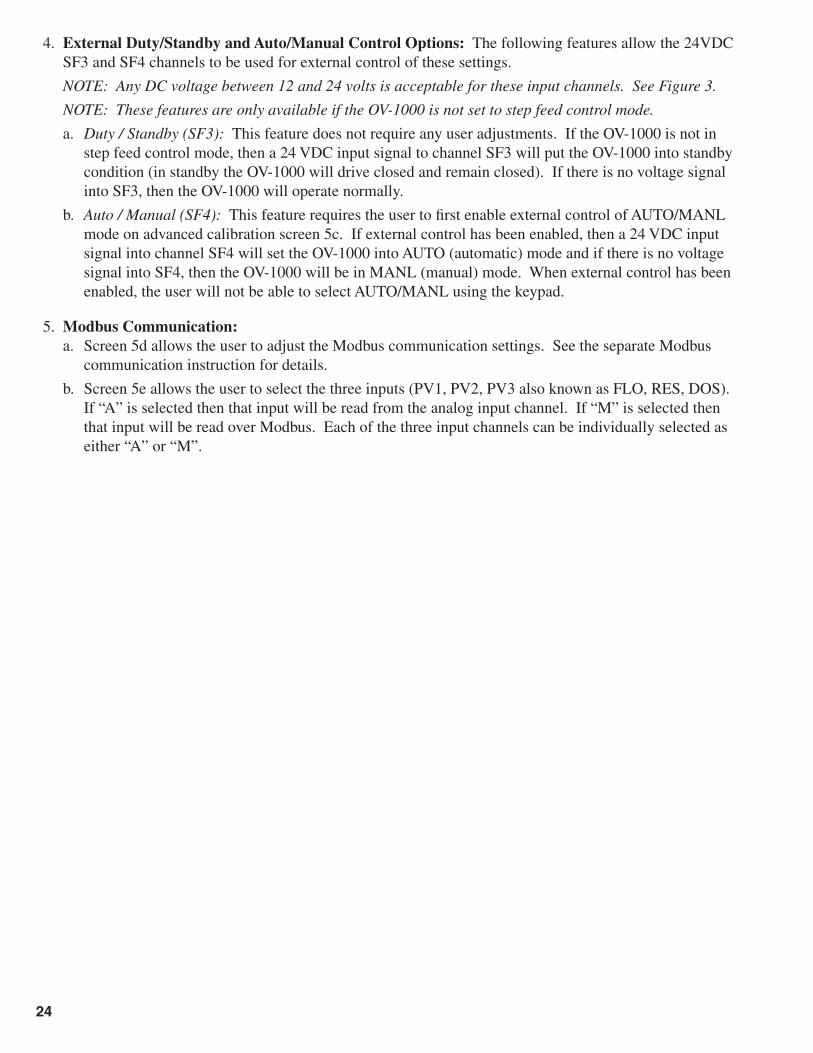
4. External Duty/Standby and Auto/Manual Control Options: The following features allow the 24VDC SF3 and SF4 channels to be used for external control of these settings.
NOTE: Any DC voltage between 12 and 24 volts is acceptable for these input channels. See Figure 3.
NOTE: These features are only available if the OV-1000 is not set to step feed control mode.
a. Duty / Standby (SF3): This feature does not require any user adjustments. If the OV-1000 is not in step feed control mode, then a 24 VDC input signal to channel SF3 will put the OV-1000 into standby condition (in standby the OV-1000 will drive closed and remain closed). If there is no voltage signal into SF3, then the OV-1000 will operate normally.
b. Auto / Manual (SF4): This feature requires the user to fi rst enable external control of AUTO/MANL mode on advanced calibration screen 5c. If external control has been enabled, then a 24 VDC input signal into channel SF4 will set the OV-1000 into AUTO (automatic) mode and if there is no voltage signal into SF4, then the OV-1000 will be in MANL (manual) mode. When external control has been enabled, the user will not be able to select AUTO/MANL using the keypad.
5. Modbus Communication: a. Screen 5d allows the user to adjust the Modbus communication settings. See the separate Modbus
communication instruction for details.
b. Screen 5e allows the user to select the three inputs (PV1, PV2, PV3 also known as FLO, RES, DOS). If “A” is selected then that input will be read from the analog input channel. If “M” is selected then that input will be read over Modbus. Each of the three input channels can be individually selected as either “A” or “M”.
24

VIII. TROUBLESHOOTING AND MAINTENANCE
1. Factory Default: If there is an electronics problem that cannot be solved by any of the below efforts, then you might consider performing a factory default. However, when this is done all calibration data is lost and must be reset. Therefore it is best to try other steps fi rst because you will have to go through both the Advance Calibration Mode and the Confi guration Mode to enter all control and calibration settings.. In order to perform a factory default follow these steps:
1. Turn off the power to the OV-1000.
2. Hold both the “up arrow” key and the “down arrow” key on the front panel.
3. While holding both keys, turn on the power to the OV-1000.
SAFETY NOTE: Be sure to follow all safety precautions before attempting to service the OV-1000 Omni-Valve. Be sure to disconnect power from the OV-1000 Omni-Valve before servicing electronics.
2. Servicing the Valve Body: (See Figures 14 and 16) If the valve becomes diffi cult to move or for the purpose of preventative maintenance (recommended every 12 to 24 months) the valve body should be serviced according to the following procedure:
a. Removal of the valve body from the monitor enclosure: i. Remove the three bolts at the bottom end of the valve body.
ii. Remove the Lower Body and Middle Body parts of the valve body assembly.
iii. Unscrew the Valve Stem and intermediate Valve Stem from the motor shaft. Avoid using pliers or any tool that will scar the surface of these parts.
iv. Unscrew and remove the three bolts inside the enclosure that hold the Upper Body to the enclosure.
b. Top Shaft Seal: Also remove the OV2-33 Seal Cap from the top of the Upper Body using a spanner wrench. There is a 3RS-108 O-Ring and Tefl on seal under this part. When reinstalling the OV2-33 Seal Cap do not over tighten. Use 7-10 inch-pounds torque.
c. Maintenance: All parts should be inspected for damage, cleaned, and lubricated* before reassembly. Generally, O-Rings should be replaced if in use for more than 12 months. The Valve Seat may require replacement if there are any cuts or burrs noticed. Hydro recommends replacement of AV2-62 during valve servicing.
* Use appropriate lubrication for your chemical application. Contact your local representative of Hydro Instruments if there is any uncertainty.
d. Reinstallation: IMPORTANT – It is critically important that the threads on the Valve Stem and Intermediate Valve Stem be securely tightened during installation. Follow this procedure:
i. Install all O-rings, Tefl on Seals, Seal Cap and Stem Seal parts into the Upper body fi rst. Then slip the Intermediate Valve Stem through the assembly.
ii. Secure the Upper Body to the enclosure being sure to use a new gasket between the two parts.
iii. Thread the Intermediate Valve Stem hand tight onto the motor shaft threaded adapter. Avoid using pliers or any tool that will scar the surface of the stem.
iv. Thread the Valve Stem hand tight onto the Intermediate Valve Stem. Avoid using pliers or any tool that will scar the surface of the stem.
v. Install the Middle Body and Lower Body being sure not to move them in a way that would possibly unthread the Intermediate Valve Stem or the Valve Stem threads.
NOTE: The bolts used to secure the valve body (3 bottom + 3 top) should be tightened to 20-25 inch-pounds torque.
25

11
7
8
9
10
6
1
2
3 4
5
OV-1000Mechanical
Subassembly
Date: 2019-02-01-v1 EXPLODED VIEW Dwg. No. OV-1000 ELE, EXPOV-1000 OMNI-VALVE
(ELECTRICAL SUBASSEMBLY)
26

Date: 2019-02-01-v1 BILL OF MATERIALS Dwg. No. OV-1000 ELE, BOMOV-1000 OMNI-VALVE
(ELECTRICAL SUBASSEMBLY)
Item Part No. Description Quantity No.
1 OV-1000 Printed Circuit Board 1 Consult Factory
2 Power Supply Board 12VDC, 2.1A 1 PSB-12VDC-OV
3 Liquid Tight Fitting 4 BLT-199
- Required O-Ring for Liquid Tight Fitting 4 OH-BUN-112
4 10-24 x 5⁄8" Pan Head Machine Screw 4 BTH-STA-244
5 Upper Body Gasket 1 AV-GASKET
6 Home Switch Assembly with Threaded Adapter 1 OV-HOMESWITCH
7 Toggle Switch 1 SWITCH-01
8 OV-1000 Stepper Motor and Home Switch 1 OV-MOTOR-1000
9 OV-1000 Mounting Plate 1 MP-1
10 OV-1000 Stand Off 4 AV-SO-3
11 Upper Body Bolt 3 BTH-STA-537 (1⁄4-20 x 1⁄2" Button Head Socket Cap Screw)
27
3
5 63
10A/B/C
12A/.../F
13A/.../D
11
1
2
2
4
7
8
9
5
8
5
8
5
14
1415
16A/B/C
17
8
1/4" NPT
1/2" NPT
1" NPT
1"NPT
1/2"NPT
1/4"NPT
12 A
12 B
12 C
12 D
12 E
12 F
13 A
13 B
13 C
13 D
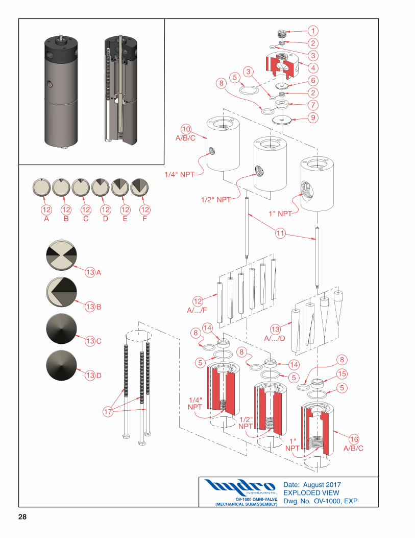
Date: August 2017 EXPLODED VIEW Dwg. No. OV-1000, EXPOV-1000 OMNI-VALVE
(MECHANICAL SUBASSEMBLY)
28

Date: August 2017 BILL OF MATERIALS Dwg. No. OV-1000, BOMOV-1000 OMNI-VALVE
(MECHANICAL SUBASSEMBLY)
Item Part No. Description Quantity No.
1 PM Seal Cap 1 OV2-33 2 PM Teflon Seal 2 OVS-108 3 PM O-Ring 2 3RS-108 4 Upper Body 1 AVB-10-2 5 PM O-Ring 2 3RS-124
6 Small Disc 1 AV-4 7 PM Stem Seal 1 OV-5 8 PM O-Ring 2 3RS-116 9 Large Disc 1 AV-3
10 A Middle Body (250 PPD) (OV-1000-1) 1 AV3-11-1-250 10 B Middle Body (500 PPD) (OV-1000-1) 1 AV3-11-1-500 10 C Middle Body (2000 PPD) (OV-1000-2) 1 AV3-11-2 11 Valve Shaft 1 AV3-1
12 A Valve Stem (10 PPD) 1 AV3-7-1-010 12 B Valve Stem (25 PPD) 1 AV3-7-1-025 12 C Valve Stem (50 PPD) 1 AV3-7-1-050 12 D Valve Stem (100 PPD) 1 AV3-7-1-100 12 E Valve Stem (250 PPD) 1 AV3-7-1-250 12 F Valve Stem (500 PPD) 1 AV3-7-1-500
13 A Valve Stem (1000 PPD) 1 AV3-7-2-1000 13 B Valve Stem (2000 PPD) 1 AV3-7-2-2000 13 C Valve Stem 8+ (2000 PPD) 1 AV3-7-2-C1 13 D Valve Stem 8++ (2000 PPD) 1 AV3-7-2-C2
14 PM Valve Stem Seat (500 PPD) 1 AV2-62 15 PM Valve Stem Seat (2000 PPD) 1 AV2-6-000 16 A Lower Body (250 PPD) (OV-1000-1) 1 AV3-9-1-250 16 B Lower Body (500 PPD) (OV-1000-1) 1 AV3-9-1-500 16 C Lower Body (2000 PPD) (OV-1000-2) 1 AV3-9-2
17 Bolts 3 1⁄4"-20 x 71⁄2" 18 A PM NPT Fitting (100 PPD) Not Shown 2 BKF-64 18 B PM NPT Fitting (250 PPD) Not Shown 2 BKF-84 18 C PM NPT Fitting (500 PPD) Not Shown 2 BKF-108
PM Part & Maintenance Kit (100 PPD) KT1-100-OV PM Part & Maintenance Kit (250 PPD) KT1-250-OV PM Part & Maintenance Kit (500 PPD) KT1-500-OV PM Part & Maintenance Kit (2000 PPD) KT1-040-OV
29

3
4 6
3
10 A
12 A/B/C 13
A/.../D
1
2
4
789
15 A A
15 B B
2
5
14
14
10 B
16
1.5" SocketConnection
11
11
2" SocketConnection
2" SocketConnection
1.5" SocketConnection
12 A 12 B 12 C
13 A
13 B
13 C
13 D
Date: August 2017 EXPLODED VIEW Dwg. No. OV-1000HC, EXPOV-1000HC HIGH CAPACITY OMNI-VALVE
(MECHANICAL SUBASSEMBLY)
30

Date: August 2017 EXPLODED VIEW Dwg. No. OV-1000HC, EXPOV-1000HC HIGH CAPACITY OMNI-VALVE
(MECHANICAL SUBASSEMBLY)
Item Part No. Description Quantity No.
1 PM Seal Cap 1 OV2-33
2 PM Teflon Seal 2 OVS-108
3 PM O-Ring 2 3RS-108
4 PM O-Ring 2 3RS-124
5 Upper Body 1 OVB-UB-6000
6 Small Disc 1 AV-4
7 PM Stem Seal 1 OV-5
8 PM O-Ring 1 3RS-116
9 Large Disc 1 AV-3
10 A Middle Body 1 AV3-11-3
10 B Middle Body 1 AV3-11-4
11 Valve Shaft 1 AV3-1
12 A Valve Stem (3000 PPD) 1 AV3-7-3-3000
12 B Valve Stem (4000 PPD) 1 AV3-7-3-4000
12 C Valve Stem (6000 PPD) 1 AV3-7-3-6000
13 A Valve Stem (4000 PPD) 1 AV3-7-4-4000
13 B Valve Stem (6000 PPD) 1 AV3-7-4-6000
13 C Valve Stem (8000 PPD) 1 AV3-7-4-8000
13 D Valve Stem (10,000 PPD) 1 AV3-7-4-10000
14 PM O-Ring 1 OH-VIT-137
15 A Lower Body 1 AV3-9-3
15 B Lower Body 1 AV3-9-4
16 Bolts 4 1⁄4"-20 x 71⁄2"
PM Part & Maintenance Kit (10,000 PPD) KT1-200-OV1
31


![j n $ ! l * · 2020. 5. 26. · n_]i iqi2j om%gij ojgi^ iiozj v@ oh ov og a ov^ ov og ## v@oh # ov og ov ^ ov og # v@oh ov og ov^ ov og aa v@ oh ov og i Õ ekkc ov og ebde ov^ ov](https://static.fdocuments.net/doc/165x107/5fdfaf2b3ee30437e40d6aeb/j-n-l-2020-5-26-ni-iqi2j-omgij-ojgi-iiozj-v-oh-ov-og-a-ov-ov-og.jpg)