Series NRX Digitrip 520/520M trip units operating …...3 Instruction Leaflet IL01301051E effective...
42
Operating Manual for Series NRX Trip Units - Digitrip™ 520/520M effective September 2013 Series NRX Instruction Leaflet IL01301051E Instructions apply to: Series NRX, Type NF Frame ANSI, UL1066, UL489 / IEC, IZMX16, IZM91 Series NRX, Type RF Frame IEC, IZMX40
Transcript of Series NRX Digitrip 520/520M trip units operating …...3 Instruction Leaflet IL01301051E effective...
Operating Manual for Series NRX Trip Units - Digitrip™ 520/520M
effective September 2013 Series NRXInstruction Leaflet IL01301051E
Instructions apply to:
1600 NRX SUB-TITLE IMAGE (12/15/2010)
Series NRX, Type NF Frame ANSI, UL1066, UL489 / IEC, IZMX16, IZM91
Series NRX, Type RF Frame IEC, IZMX40
4000 NRX RF DRAWOUT SUBTITLE IMAGE (12/15/2010)

2
Operating Manual for Series NRX Trip Units - Digitrip™ 520/520M
EATON www.eaton.com
Instruction Leaflet IL01301051Eeffective September 2013
3
Instruction Leaflet IL01301051Eeffective September 2013
Operating Manual for Series NRX Trip Units - Digitrip™ 520/520M
EATON www.eaton.com
• WARNING! DANGEROUS ELECTRICAL VOLTAGE!DO NOT ATTEMPT TO INSTALL OR PERFORM MAINTENANCE ON EQUIPMENT WHILE IT IS ENERGIZED. DEATH OR SEVERE PERSONAL INJURY CAN RESULT FROM CONTACT WITH ENERGIZED EQUIPMENT. ALWAYS VERIFY THAT NO VOLTAGE IS PRESENT BEFORE PROCEEDING. ALWAYS FOLLOW SAFETY PROCEDURES. EATON IS NOT LIABLE FOR THE MISAPPLICATION OR MISINSTALLATION OF ITS PRODUCTS.
• WARNINGOBSERVE ALL RECOMMENDATIONS, NOTES, CAUTIONS, AND WARNINGS RELATING TO THE SAFETY OF PERSONNEL AND EQUIPMENT. OBSERVE AND COMPLY WITH ALL GENERAL AND LOCAL HEALTH AND SAFETY LAWS, CODES, AND PROCEDURES.
Before commencing the installation
• Disconnect the power supply of the device
• Ensure that devices cannot be accidentally restarted
• Verify isolation from the supply. Earth and short circuit
• Cover or enclose neighboring units that are live
• Danger if breaker mechanism spring is charged! Discharge spring
• Follow the engineering instructions of the device concerned
• Only suitably qualified personnel in accordance with applicable national work safety regulations may work on this device/system
• Before installation and before touching the device ensure that you are free of electrostatic charge
• Connecting cables and signal lines should be installed so that induc-tive or capacitive interference do not impair the automation func-tions
• Suitable safety hardware and software measures should be imple-mented for the I/O interface so that a line or wire breakage on the signal side does not result in undefined states in the automation devices
• Deviations of the mains voltage from the rated value must not exceed the tolerance limits given in the specifications, otherwise this may cause malfunction and dangerous operation
• Emergency stop devices complying with IEC 60204-1, EN 60204-1 must be effective in all operating modes of the automation devices. Unlatching the emergency-stop devices must not cause restart
• The electrical installation must be carried out in accordance with the relevant regulations (e. g. with regard to cable cross sections, fuses, PE)
• All work relating to transport, installation, commissioning and main-tenance must only be carried out by qualified personnel in accor-dance with applicable national work safety regulations
Noee:N The recNmmendaoiNns and infNrmaoiNn cNnoained herein are based Nn experience and judgemeno, buo shNuld nNo be cNnsidered oN be all inclusive Nr oN cNver every applicaoiNn Nr circumsoance ohao may arise.
If you have any questions or need further information or instructions, please contact your local Eaton representative or visit www.eaton.com.
4
Operating Manual for Series NRX Trip Units - Digitrip™ 520/520M
EATON www.eaton.com
Instruction Leaflet IL01301051Eeffective September 2013
Contents page page
Section 1: General description of Digitrip trip units in Eaton Series NRX circuit breakers . . . . . . . . . . . . . . . . . . . . . . . . 6
Sensors . . . . . . . . . . . . . . . . . . . . . . . . . . . . . . . . . . . . . . . . . . . . 6Digitrip Trip Unit . . . . . . . . . . . . . . . . . . . . . . . . . . . . . . . . . . . . . . 6Low-energy trip actuator . . . . . . . . . . . . . . . . . . . . . . . . . . . . . . . 6Catalog Number Referencing . . . . . . . . . . . . . . . . . . . . . . . . . . . . 6Protection . . . . . . . . . . . . . . . . . . . . . . . . . . . . . . . . . . . . . . . . . . . 6Mode of trip and status information . . . . . . . . . . . . . . . . . . . . . . 7Installation and removal . . . . . . . . . . . . . . . . . . . . . . . . . . . . . . . 11Trip unit/rating plug removal . . . . . . . . . . . . . . . . . . . . . . . . . . . . 11Wiring . . . . . . . . . . . . . . . . . . . . . . . . . . . . . . . . . . . . . . . . . . . . . 11Plexiglass cover . . . . . . . . . . . . . . . . . . . . . . . . . . . . . . . . . . . . . 11Voltage supply input/alarms . . . . . . . . . . . . . . . . . . . . . . . . . . . . 11Display feature (Digitrip 520M only) . . . . . . . . . . . . . . . . . . . . . 12Standards . . . . . . . . . . . . . . . . . . . . . . . . . . . . . . . . . . . . . . . . . . 12
Section 2: Principles of operation . . . . . . . . . . . . . . . . . . . . . . . . . 12Trip and operation indicators . . . . . . . . . . . . . . . . . . . . . . . . . . . 12Making current release (MCR) . . . . . . . . . . . . . . . . . . . . . . . . . . 12High instantaneous . . . . . . . . . . . . . . . . . . . . . . . . . . . . . . . . . . 13Diagnostics indicator—circuit breaker/trip unit . . . . . . . . . . . . . 14Ground Fault Protection . . . . . . . . . . . . . . . . . . . . . . . . . . . . . . . 14
Section 3: Protection settings . . . . . . . . . . . . . . . . . . . . . . . . . . . . 15Long delay settings . . . . . . . . . . . . . . . . . . . . . . . . . . . . . . . . . . 15Short delay settings . . . . . . . . . . . . . . . . . . . . . . . . . . . . . . . . . . 16Instantaneous settings . . . . . . . . . . . . . . . . . . . . . . . . . . . . . . . . 16
Section 4: Test procedures . . . . . . . . . . . . . . . . . . . . . . . . . . . . . . 21When to test . . . . . . . . . . . . . . . . . . . . . . . . . . . . . . . . . . . . . . . 21Functional field testing . . . . . . . . . . . . . . . . . . . . . . . . . . . . . . . . 21Functional test kit (handheld) . . . . . . . . . . . . . . . . . . . . . . . . . . . 21Test procedure . . . . . . . . . . . . . . . . . . . . . . . . . . . . . . . . . . . . . . 21Ground (Earth) Fault Performance Testing . . . . . . . . . . . . . . . . . 21
Section 5: Trip unit battery . . . . . . . . . . . . . . . . . . . . . . . . . . . . . . . 22Battery check . . . . . . . . . . . . . . . . . . . . . . . . . . . . . . . . . . . . . . . 22Battery installation and removal . . . . . . . . . . . . . . . . . . . . . . . . . 22
Section 6: Rating plugs . . . . . . . . . . . . . . . . . . . . . . . . . . . . . . . . . 23Section 7: Maintenance Mode feature . . . . . . . . . . . . . . . . . . . . . 25
Arcflash Reduction Maintenance System™ mode (ARMS) . . . . 25Maintenance Mode . . . . . . . . . . . . . . . . . . . . . . . . . . . . . . . . . . 25Maintenance Mode current setting . . . . . . . . . . . . . . . . . . . . . . 25Actuating Maintenance Mode . . . . . . . . . . . . . . . . . . . . . . . . . . 25Remote indication of Maintenance Mode . . . . . . . . . . . . . . . . 25Tripping and testing . . . . . . . . . . . . . . . . . . . . . . . . . . . . . . . . . . 25
Section 8: Communication Adapter Modules (CAM) . . . . . . . . . . . . . . . . . . . . . . . . . . . . . . . . . . . . . . . 25Section 9: References . . . . . . . . . . . . . . . . . . . . . . . . . . . . . . . . . . 26
Time-current curves . . . . . . . . . . . . . . . . . . . . . . . . . . . . . . . . . . 26Curve Select . . . . . . . . . . . . . . . . . . . . . . . . . . . . . . . . . . . . . . . . 26
Appendix A: Zone interlocking examples . . . . . . . . . . . . . . . . . . . 27Appendix B: Troubleshooting . . . . . . . . . . . . . . . . . . . . . . . . . . . . . 27Appendix C: Specifications . . . . . . . . . . . . . . . . . . . . . . . . . . . . . . 28Appendix D: Performance testing for ground fault trip units primary injection . . . . . . . . . . . . . . . . . . . . . . . . . . . . . . . . . . . . . . 31
Record keeping . . . . . . . . . . . . . . . . . . . . . . . . . . . . . . . . . . . . . 32Appendix E: Typical breaker master connection diagram - NF . . . 35
Notes for previous page (Diagram drawing number 6D32389 - NF Frame . . . . . . . . . . . . . . . . . . . . . . . . . . . . . . . . . 36
Appendix F: Typical breaker master connection diagram - RF . . . . 37Notes for pages 36 and 37 (Diagram drawing number 6D32424 - RF Frame) . . . . . . . . . . . . . . . . . . . . . . . . . . . . . . . . . 39
5
Instruction Leaflet IL01301051Eeffective September 2013
Operating Manual for Series NRX Trip Units - Digitrip™ 520/520M
EATON www.eaton.com
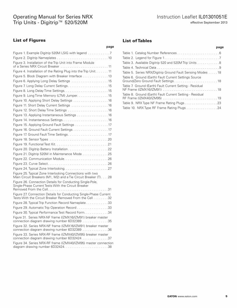
List of Figures page
List of Tables page
Figure 1. Example Digitrip 520M LSIG with legend . . . . . . . . . . . . 7Figure 2. Digitrip Nameplates . . . . . . . . . . . . . . . . . . . . . . . . . . . . 10Figure 3. Installation of the Trip Unit into Frame Module of a Series NRX Circuit Breaker . . . . . . . . . . . . . . . . . . . . . . . . . . 11Figure 4. Installation of the Rating Plug into the Trip Unit . . . . . . . 11Figure 5. Block Diagram with Breaker Interface . . . . . . . . . . . . . . 13Figure 6. Applying Long Delay Settings . . . . . . . . . . . . . . . . . . . . 15Figure 7. Long Delay Current Settings . . . . . . . . . . . . . . . . . . . . . . 15Figure 8. Long Delay Time Settings . . . . . . . . . . . . . . . . . . . . . . . . 15Figure 9. Long Time Memory (LTM) Jumper . . . . . . . . . . . . . . . . . 15Figure 10. Applying Short Delay Settings . . . . . . . . . . . . . . . . . . . 16Figure 11. Short Delay Current Settings . . . . . . . . . . . . . . . . . . . . 16Figure 12. Short Delay Time Settings . . . . . . . . . . . . . . . . . . . . . . 16Figure 13. Applying Instantaneous Settings . . . . . . . . . . . . . . . . . 16Figure 14. Instantaneous Settings . . . . . . . . . . . . . . . . . . . . . . . . . 16Figure 15. Applying Ground Fault Settings . . . . . . . . . . . . . . . . . . 17Figure 16. Ground Fault Current Settings . . . . . . . . . . . . . . . . . . . 17Figure 17. Ground Fault Time Settings . . . . . . . . . . . . . . . . . . . . . . 17Figure 18. Sensor Types . . . . . . . . . . . . . . . . . . . . . . . . . . . . . . . . 20Figure 19. Functional Test Kit . . . . . . . . . . . . . . . . . . . . . . . . . . . . . 21Figure 20. Digitrip Battery Installation . . . . . . . . . . . . . . . . . . . . . . 22Figure 21. Digitrip 520M in Maintenance Mode . . . . . . . . . . . . . . 25Figure 22. Communication Module . . . . . . . . . . . . . . . . . . . . . . . . 26Figure 23. Curve Select . . . . . . . . . . . . . . . . . . . . . . . . . . . . . . . . . 26Figure 24. Typical Zone Interlocking . . . . . . . . . . . . . . . . . . . . . . . . 27Figure 25. Typical Zone Interlocking Connections with two Main Circuit Breakers (M1, M2) and a Tie Circuit Breaker (T) . . . . 28Figure 26. Connection Details for Conducting Single-Pole, Single-Phase Current Tests With the Circuit Breaker Removed From the Cell . . . . . . . . . . . . . . . . . . . . . . . . . . . . . . . . . 31Figure 27. Connection Details for Conducting Single-Phase Current Tests With the Circuit Breaker Removed From the Cell . . . . . . . . 32Figure 28. Typical Trip Function Record Nameplate . . . . . . . . . . . . 33Figure 29. Automatic Trip Operation Record . . . . . . . . . . . . . . . . . 33Figure 30. Typical Performance Test Record Form . . . . . . . . . . . . . 34Figure 31. Series NRX-NF frame (IZMX16/IZM91) breaker master connection diagram drawing number 6D32389 . . . . . . . . . . . . . . 35Figure 32. Series NRX-NF frame (IZMX16/IZM91) breaker master connection diagram drawing number 6D32389 . . . . . . . . . . . . . . 36Figure 33. Series NRX-RF frame (IZMX40/IZM95) breaker master connection diagram drawing number 6D32424 . . . . . . . . . . . . . . 37Figure 34. Series NRX-RF frame (IZMX40/IZM95) master connection diagram drawing number 6D32424 . . . . . . . . . . . . . . . . . . . . . . . . 38
Table 1. Catalog Number References . . . . . . . . . . . . . . . . . . . . . . . 6Table 2. Legend for Figure 1 . . . . . . . . . . . . . . . . . . . . . . . . . . . . . . 7Table 3. Available Digitrip 520 and 520M Trip Units . . . . . . . . . . . . 8Table 4. Technical Data . . . . . . . . . . . . . . . . . . . . . . . . . . . . . . . . . . 9Table 5. Series NRX/Digitrip Ground Fault Sensing Modes . . . . . 18Table 6. Ground (Earth) Fault Current Settings Source Ground/Zero Ground Fault Settings . . . . . . . . . . . . . . . . . . . . . . . . 18Table 7. Ground (Earth) Fault Current Setting - Residual NF Frame (IZMX16/IZM91) . . . . . . . . . . . . . . . . . . . . . . . . . . . . . . 18Table 8. Ground (Earth) Fault Current Setting - Residual RF Frame (IZMX40/IZM95) . . . . . . . . . . . . . . . . . . . . . . . . . . . . . . 19Table 9. NRX Type NF Frame Rating Plugs . . . . . . . . . . . . . . . . . . 23Table 10. NRX Type RF Frame Rating Plugs . . . . . . . . . . . . . . . . . 24
6
Operating Manual for Series NRX Trip Units - Digitrip™ 520/520M
EATON www.eaton.com
Instruction Leaflet IL01301051Eeffective September 2013
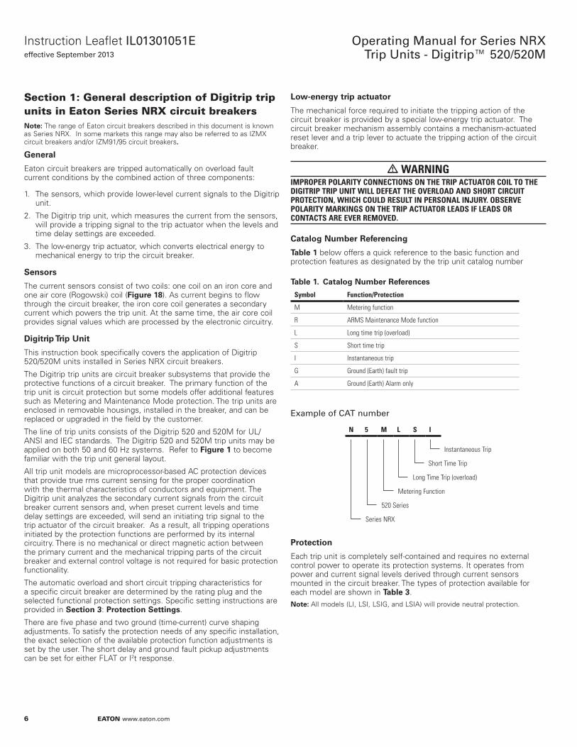
Section 1: General description of Digitrip trip units in Eaton Series NRX circuit breakers
Noee:N The range of Eaton circuit breakers described in this document is known as Series NRX. In some markets this range may also be referred to as IZMX circuit breakers and/or IZM91/95 circuit breakers.
General
Eaton circuit breakers are tripped automatically on overload fault current conditions by the combined action of three components:
1. The sensors, which provide lower-level current signals to the Digitrip unit.
2. The Digitrip trip unit, which measures the current from the sensors, will provide a tripping signal to the trip actuator when the levels and time delay settings are exceeded.
3. The low-energy trip actuator, which converts electrical energy to mechanical energy to trip the circuit breaker.
SensNrs
The current sensors consist of two coils: one coil on an iron core and one air core (Rogowski) coil (Figure 18). As current begins to flow through the circuit breaker, the iron core coil generates a secondary current which powers the trip unit. At the same time, the air core coil provides signal values which are processed by the electronic circuitry.
Digiorip Trip Unio
This instruction book specifically covers the application of Digitrip 520/520M units installed in Series NRX circuit breakers.
The Digitrip trip units are circuit breaker subsystems that provide the protective functions of a circuit breaker. The primary function of the trip unit is circuit protection but some models offer additional features such as Metering and Maintenance Mode protection. The trip units are enclosed in removable housings, installed in the breaker, and can be replaced or upgraded in the field by the customer.
The line of trip units consists of the Digitrip 520 and 520M for UL/ANSI and IEC standards. The Digitrip 520 and 520M trip units may be applied on both 50 and 60 Hz systems. Refer to Figure 1 to become familiar with the trip unit general layout.
All trip unit models are microprocessor-based AC protection devices that provide true rms current sensing for the proper coordination with the thermal characteristics of conductors and equipment. The Digitrip unit analyzes the secondary current signals from the circuit breaker current sensors and, when preset current levels and time delay settings are exceeded, will send an initiating trip signal to the trip actuator of the circuit breaker. As a result, all tripping operations initiated by the protection functions are performed by its internal circuitry. There is no mechanical or direct magnetic action between the primary current and the mechanical tripping parts of the circuit breaker and external control voltage is not required for basic protection functionality.
The automatic overload and short circuit tripping characteristics for a specific circuit breaker are determined by the rating plug and the selected functional protection settings. Specific setting instructions are provided in SecoiNn 3: PrNoecoiNn Seooings.
There are five phase and two ground (time-current) curve shaping adjustments. To satisfy the protection needs of any specific installation, the exact selection of the available protection function adjustments is set by the user. The short delay and ground fault pickup adjustments can be set for either FLAT or I2t response.
LNw-energy orip acouaoNr
The mechanical force required to initiate the tripping action of the circuit breaker is provided by a special low-energy trip actuator. The circuit breaker mechanism assembly contains a mechanism-actuated reset lever and a trip lever to actuate the tripping action of the circuit breaker.
• WARNINGIMPROPER POLARITY CONNECTIONS ON THE TRIP ACTUATOR COIL TO THE DIGITRIP TRIP UNIT WILL DEFEAT THE OVERLOAD AND SHORT CIRCUIT PROTECTION, WHICH COULD RESULT IN PERSONAL INJURY. OBSERVE POLARITY MARKINGS ON THE TRIP ACTUATOR LEADS IF LEADS OR CONTACTS ARE EVER REMOVED.
CaoalNg Number Referencing
Table 1 below offers a quick reference to the basic function and protection features as designated by the trip unit catalog number
Table 1. CaoalNg Number References
Symbol Function/Protection
M Metering function
R ARMS Maintenance Mode function
L Long time trip (overload)
S Short time trip
I Instantaneous trip
G Ground (Earth) fault trip
A Ground (Earth) Alarm only
Example of CAT number
N 5 M L S I
Instantaneous Trip
Short Time Trip
Long Time Trip (overload)
Metering Function
Series NRX
520 Series
PrNoecoiNn
Each trip unit is completely self-contained and requires no external control power to operate its protection systems. It operates from power and current signal levels derived through current sensors mounted in the circuit breaker. The types of protection available for each model are shown in Table 3.NNoee: All models (LI, LSI, LSIG, and LSIA) will provide neutral protection.
7
Instruction Leaflet IL01301051Eeffective September 2013
Operating Manual for Series NRX Trip Units - Digitrip™ 520/520M
EATON www.eaton.com
Figure 1.
5 6
5 6
5 6
56
7
7
78
3
2
4
1
9 10
11 12
13
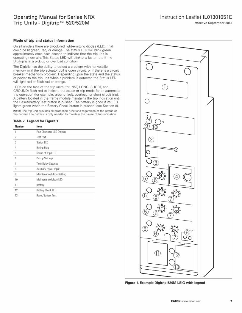
Example Digiorip 520M LSIG wioh legend
MNde Nf orip and soaous infNrmaoiNn
On all models there are tri-colored light-emitting diodes (LED), that could be lit green, red, or orange. The status LED will blink green approximately once each second to indicate that the trip unit is operating normally. This Status LED will blink at a faster rate if the Digitrip is in a pick-up or overload condition.
The Digitrip has the ability to detect a problem with nonvolatile memory or if the trip actuator coil is open circuit, or if there is a circuit breaker mechanism problem. Depending upon the state and the status of power to the trip unit when a problem is detected the Status LED will light red or flash red or orange.
LEDs on the face of the trip units (for INST, LONG, SHORT, and GROUND) flash red to indicate the cause or trip mode for an automatic trip operation (for example, ground fault, overload, or short circuit trip). A battery located in the frame module maintains the trip indication until the Reset/Battery Test button is pushed. The battery is good if its LED lights green when the Battery Check button is pushed (see Section 8).NNoee: The trip unit provides all protection functions regardless of the status of the battery. The battery is only needed to maintain the cause of trip indication.
Table 2. Legend fNr Figure 1
Number Item
1 Four-Character LCD Display
2 Test Port
3 Status LED
4 Rating Plug
5 Cause of Trip LED
6 Pickup Settings
7 Time Delay Settings
8 Auxiliary Power Input
9 Maintenance Mode Setting
10 Maintenance Mode LED
11 Battery
12 Battery Check LED
13 Reset/Battery Test
8
Operating Manual for Series NRX Trip Units - Digitrip™ 520/520M
EATON www.eaton.com
Instruction Leaflet IL01301051Eeffective September 2013
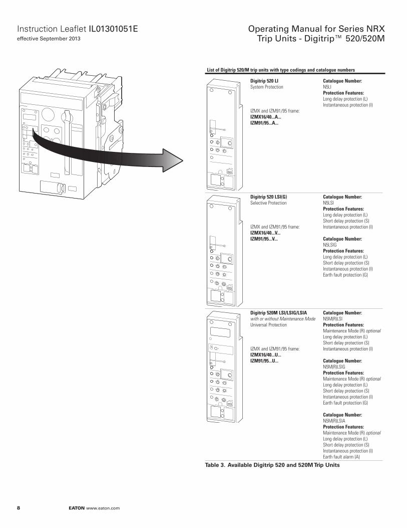
List of Digitrip 520/M trip units with type codings and catalogue numbers
Digitrip 520 LISystem Protection
IZMX and IZM91/95 frame:IZMX16/40...A...IZM91/95...A...
Catalogue Number:N5LIProtection Features:Long delay protection (L)Instantaneous protection (I)
Digitrip 520 LSI(G)Selective Protection
IZMX and IZM91/95 frame:IZMX16/40...V... IZM91/95...V...
Catalogue Number:N5LSIProtection Features:Long delay protection (L)Short delay protection (S)Instantaneous protection (I)
Catalogue Number:N5LSIGProtection Features:Long delay protection (L)Short delay protection (S)Instantaneous protection (I)Earth fault protection (G)
Digitrip 520M LSI/LSIG/LSIAwith or without Maintenance ModeUniversal Protection
IZMX and IZM91/95 frame:IZMX16/40...U... IZM91/95...U...
Catalogue Number:N5M(R)LSIProtection Features:Maintenance Mode (R) optionalLong delay protection (L)Short delay protection (S)Instantaneous protection (I)
Catalogue Number:N5M(R)LSIGProtection Features:Maintenance Mode (R) optionalLong delay protection (L)Short delay protection (S)Instantaneous protection (I)Earth fault protection (G)
Catalogue Number:N5M(R)LSIAProtection Features:Maintenance Mode (R) optionalLong delay protection (L)Short delay protection (S)Instantaneous protection (I)Earth fault alarm (A)
Table 3. Available Digiorip 520 and 520M Trip Unios
9
Instruction Leaflet IL01301051Eeffective September 2013
Operating Manual for Series NRX Trip Units - Digitrip™ 520/520M
EATON www.eaton.com
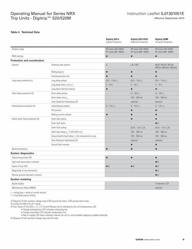
Table 4. Technical Daoa
Digitrip 520 LISystem Protection
Digitrip 520 LSI(G)Selective Protection
Digitrip 520MUniversal Protection
Ampere range NF frame 200-1600ARF frame 800- 4000A
NF frame 200-1600ARF frame 800- 4000A
NF frame 200-1600ARF frame 800- 4000A
RMS sensing l l l
PrNoecoiNn and cNNrdinaoiNn
General Ordering style options LI LSI, LSIG MLSI, MLSIG, MLSIA, MRLSI, MRLSIG, MRLSIA
Rating plug (In) l l l
Overtemperature trip l l l
Long delay protection (L) Long delay pickup (0.5 – 1.0) x In (0.5 – 1.0) x In (0.5 – 1.0) x In
Long delay time tr at 6 x Ir 2 – 24 s 2 – 24 s 2 – 24 s
Long delay thermal memory l l l
Short delay protection (S) Short delay pickup - (2 - 10) x Ir (2 - 10) x Ir
Short delay time tsd - 100 – 500 ms 100 – 500 ms
Zone Selective Interlocking ZSI - optional optional
Instantaneous protection (I) Instantaneous pickup (2 - 12) x In (2 - 12) x In (2 - 12) x In
Off position - l l
Making current release l l l
Option earth fault protection (G) Earth fault option - l l
Earth fault alarm - - l
Earth fault pickup - (0.25 - 1.0) x In (0.25 - 1.0) x In
Earth fault delay tg , I2t @ 0.625 x (In) - 100 – 500 ms 100 – 500 ms
Ground (earth) fault delay tg, flat characteristic curve - 100 – 500 ms 100 – 500 ms
Zone Selective Interlocking ZSI - optional optional
Ground fault memory - l l
Neutral protection l l l
Sysoem diagnNsoics
Status/long pickup LED l l l
High load alarm/alarm contacts - - l
Cause of trip LEDs l l l
Magnitude of trip information - - l
Remote ground trip/alarm contacts - - l
Sysoem meoering
Digital display - - 4 character LCD
Maintenance Mode (ARMS) - - optional
In = rating plug = rating of current sensorsIr = Long delay pickup setting
Requires 24 Vdc auxiliary voltage input (LSIG-ground trip alarm, LSIA ground alarm only). Limited to1200 A for UL® rating Four Cause of Trip LEDs: L, S, I, G. Current Release trip is indicated by the red instantaneous LED: • Orange Instantaneous LED indicates rating plug trip • Orange Long Delay LED indicates temperature trip • Red or orange LED status indicates internal trip unit or circuit breaker diagnostic problem detected. Requires 24 Vdc auxiliary voltage input and LSI style.
10
Operating Manual for Series NRX Trip Units - Digitrip™ 520/520M
EATON www.eaton.com
Instruction Leaflet IL01301051Eeffective September 2013
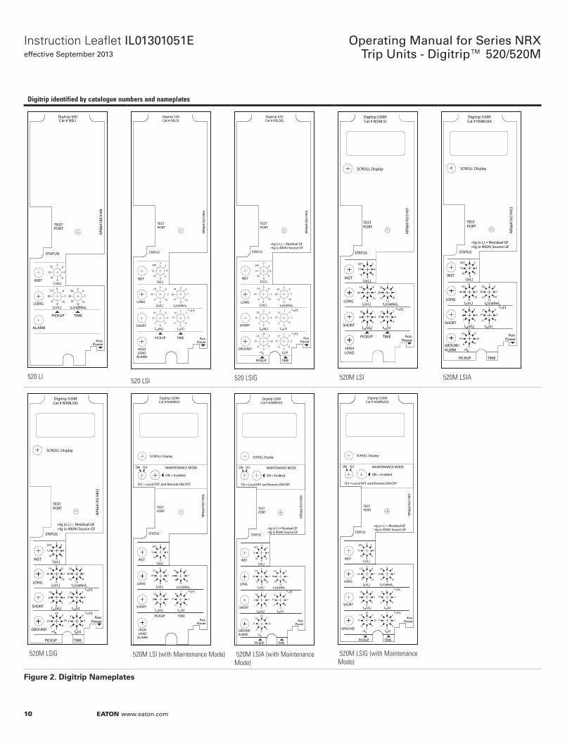
Digitrip identified by catalogue numbers and nameplates
Digitrip 520Cat # N5LI
TESTPORT
NP
66A
7651
H09
STATUS
INST
LONG
ALARM
Aux.Power
tR(s)@6xIR 12
15
20
242
4
7
10
lR(xIn).8
.9
.95
1.0.5
.6
.7
.75
li(xIn)8
10
12
122
3
4
6
PICKUP TIME
520 LI
Digitrip 520Cat # N5LSI
TESTPORT
NP6
6A76
51H
04
STATUS
INST
LONG
SHORT
HIGHLOAD
ALARM
Aux.Power
tsd(s).5
.1*
.3*
.5*.1
.2
.3
.4
*=l2t
lsd(xIR)6
7
8
102
3
4
5
tR(s)@6xIR 12
15
20
242
4
7
10
lR(xIn).8
.9
.95
1.0.5
.6
.7
.75
li(xIn)8
10
12
OFF2
3
4
6
PICKUP TIME
520 LSI
••lg (x In) = Residual GF••lg (x 400A) Source GF
Digitrip 520Cat # N5LSIG
TESTPORT
NP6
6A76
51H
05
STATUS
GROUND
PICKUP TIME
Aux.Power
tg(s).5
.1*
.3*
.5*.1
.2
.3
.4
*=l2t
••lg.5
.6
.75
1.0.25
.3
.35
.4
INST
LONG
SHORTtsd(s)
.5.1*
.3*
.5*.1
.2
.3
.4
*=l2t
lsd(xIR)6
7
8
102
3
4
5
tR(s)@6xIR 12
15
20
242
4
7
10
lR(xIn).8
.9
.95
1.0.5
.6
.7
.75
li(xIn)8
10
12
OFF2
3
4
6
520 LSIG
Digitrip 520MCat # N5MLSI
SCROLL Display
TESTPORT
NP6
6A76
51H
01
STATUS
INST
LONG
SHORT
HIGHLOAD
Aux.Power
tsd(s).5
.1*
.3*
.5*.1
.2
.3
.4
*=l2t
lsd(xIR)6
7
8
102
3
4
5
tR(s)@6xIR 12
15
20
242
4
7
10
lR(xIn).8
.9
.95
1.0.5
.6
.7
.75
li(xIn)8
10
12
OFF2
3
4
6
PICKUP TIME
520M LSI
SCROLL Display
••lg (x In) = Residual GF••lg (x 400A) Source GF
Digitrip 520MCat # N5MLSIA
TESTPORT
NP6
6A76
51H
03
STATUS
GROUNDALARM
PICKUP TIME
Aux.Power
••lg.5
.6
.75
1.0.25
.3
.35
.4
INST
LONG
SHORTtsd(s)
.5.1*
.3*
.5*.1
.2
.3
.4
*=l2t
lsd(xIR)6
7
8
102
3
4
5
tR(s)@6xIR 12
15
20
242
4
7
10
lR(xIn).8
.9
.95
1.0.5
.6
.7
.75
li(xIn)8
10
12
OFF2
3
4
6
520M LSIA
••lg (x In) = Residual GF••lg (x 400A) Source GF
Digitrip 520MCat # N5MLSIG
SCROLL Display
TESTPORT
NP6
6A76
51H
02
STATUS
GROUND
PICKUP TIME
Aux.Power
tg(s).5
.1*
.3*
.5*.1
.2
.3
.4
*=l2t
••lg.5
.6
.75
1.0.25
.3
.35
.4
INST
LONG
SHORT tsd(s).5
.1*
.3*
.5*.1
.2
.3
.4
*=l2t
lsd(xIR)6
7
8
102
3
4
5
tR(s)@6xIR 12
15
20
242
4
7
10
lR(xIn).8
.9
.95
1.0.5
.6
.7
.75
li(xIn)8
10
12
OFF2
3
4
6
520M LSIG
Digitrip 520MCat # N5MRLSI
SCROLL Display
TESTPORT
NP6
6A76
51H
06
STATUS
INST
LONG
SHORT
HIGHLOAD
ALARM
Aux.Power
tsd(s).5
.1*
.3*
.5*.1
.2
.3
.4
*=l2t
lsd(xIR)6
7
8
102
3
4
5
tR(s)@6xIR 12
15
20
242
4
7
10
lR(xIn).8
.9
.95
1.0.5
.6
.7
.75
li(xIn)8
10
12
OFF2
3
4
6
PICKUP TIME
MAINTENANCE MODE
ON = Enabled
O/I = Local OFF and Remote ON/OFF
O/ION
520M LSI (with Maintenance Mode)
••lg (x In) = Residual GF••lg (x 400A) Source GF
Digitrip 520MCat # N5MRLSIA
SCROLL Display
TESTPORT
NP6
6A76
51H
08
STATUS
GROUNDALARM
PICKUP TIME
Aux.Power
••lg.5
.6
.75
1.0.25
.3
.35
.4
INST
LONG
SHORTtsd(s)
.5.1*
.3*
.5*.1
.2
.3
.4
*=l2t
lsd(xIR)6
7
8
102
3
4
5
tR(s)@6xIR 12
15
20
242
4
7
10
lR(xIn).8
.9
.95
1.0.5
.6
.7
.75
li(xIn)8
10
12
OFF2
3
4
6
MAINTENANCE MODE
ON = Enabled
O/I = Local OFF and Remote ON/OFF
O/ION
520M LSIA (with Maintenance Mode)
••lg (x In) = Residual GF••lg (x 400A) Source GF
Digitrip 520MCat # N5MRLSIG
SCROLL Display
TESTPORT
NP6
6A76
51H
07
STATUS
GROUND
PICKUP TIME
Aux.Power
tg(s).5
.1*
.3*
.5*.1
.2
.3
.4
*=l2t
••lg.5
.6
.75
1.0.25
.3
.35
.4
INST
LONG
SHORTtsd(s)
.5.1*
.3*
.5*.1
.2
.3
.4
*=l2t
lsd(xIR)6
7
8
102
3
4
5
tR(s)@6xIR 12
15
20
242
4
7
10
lR(xIn).8
.9
.95
1.0.5
.6
.7
.75
li(xIn)8
10
12
OFF2
3
4
6
MAINTENANCE MODE
ON = Enabled
O/I = Local OFF and Remote ON/OFF
O/ION
520M LSIG (with Maintenance Mode)
Figure 2. Digiorip Nameplaoes
11
Instruction Leaflet IL01301051Eeffective September 2013
Operating Manual for Series NRX Trip Units - Digitrip™ 520/520M
EATON www.eaton.com
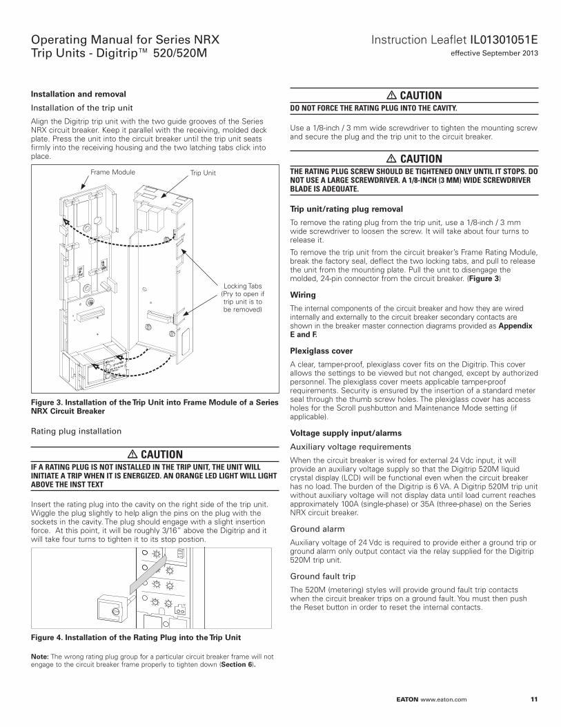
InsoallaoiNn and remNval
Installation of the trip unit
Align the Digitrip trip unit with the two guide grooves of the Series NRX circuit breaker. Keep it parallel with the receiving, molded deck plate. Press the unit into the circuit breaker until the trip unit seats firmly into the receiving housing and the two latching tabs click into place.
Figure 3.
Frame Module Trip Unit
Locking Tabs (Pry to open if trip unit is to be removed)
InsoallaoiNn Nf ohe Trip Unio inoN Frame MNdule Nf a Series NRX Circuio Breaker
Rating plug installation
• CAUTIONIF A RATING PLUG IS NOT INSTALLED IN THE TRIP UNIT, THE UNIT WILL INITIATE A TRIP WHEN IT IS ENERGIZED. AN ORANGE LED LIGHT WILL LIGHT ABOVE THE INST TEXT
Insert the rating plug into the cavity on the right side of the trip unit. Wiggle the plug slightly to help align the pins on the plug with the sockets in the cavity. The plug should engage with a slight insertion force. At this point, it will be roughly 3/16” above the Digitrip and it will take four turns to tighten it to its stop postion.
Figure 4. InsoallaoiNn Nf ohe Raoing Plug inoN ohe Trip Unio
Noee:N The wrong rating plug group for a particular circuit breaker frame will not engage to the circuit breaker frame properly to tighten down (SecoiNn 6).
• CAUTIONDO NOT FORCE THE RATING PLUG INTO THE CAVITY.
Use a 1/8-inch / 3 mm wide screwdriver to tighten the mounting screw and secure the plug and the trip unit to the circuit breaker.
• CAUTIONTHE RATING PLUG SCREW SHOULD BE TIGHTENED ONLY UNTIL IT STOPS. DO NOT USE A LARGE SCREWDRIVER. A 1/8-INCH (3 MM) WIDE SCREWDRIVER BLADE IS ADEQUATE.
Trip unio/raoing plug remNval
To remove the rating plug from the trip unit, use a 1/8-inch / 3 mm wide screwdriver to loosen the screw. It will take about four turns to release it.
To remove the trip unit from the circuit breaker’s Frame Rating Module, break the factory seal, deflect the two locking tabs, and pull to release the unit from the mounting plate. Pull the unit to disengage the molded, 24-pin connector from the circuit breaker. (Figure 3)
Wiring
The internal components of the circuit breaker and how they are wired internally and externally to the circuit breaker secondary contacts are shown in the breaker master connection diagrams provided as Appendix E and F.
Plexiglass cNver
A clear, tamper-proof, plexiglass cover fits on the Digitrip. This cover allows the settings to be viewed but not changed, except by authorized personnel. The plexiglass cover meets applicable tamper-proof requirements. Security is ensured by the insertion of a standard meter seal through the thumb screw holes. The plexiglass cover has access holes for the Scroll pushbutton and Maintenance Mode setting (if applicable).
VNloage supply inpuo/alarms
Auxiliary voltage requirements
When the circuit breaker is wired for external 24 Vdc input, it will provide an auxiliary voltage supply so that the Digitrip 520M liquid crystal display (LCD) will be functional even when the circuit breaker has no load. The burden of the Digitrip is 6 VA. A Digitrip 520M trip unit without auxiliary voltage will not display data until load current reaches approximately 100A (single-phase) or 35A (three-phase) on the Series NRX circuit breaker.
Ground alarm
Auxiliary voltage of 24 Vdc is required to provide either a ground trip or ground alarm only output contact via the relay supplied for the Digitrip 520M trip unit.
Ground fault trip
The 520M (metering) styles will provide ground fault trip contacts when the circuit breaker trips on a ground fault. You must then push the Reset button in order to reset the internal contacts.
12
Operating Manual for Series NRX Trip Units - Digitrip™ 520/520M
EATON www.eaton.com
Instruction Leaflet IL01301051Eeffective September 2013
Ground fault alarm
A ground fault alarm alerts a user to a ground fault condition without tripping the circuit breaker. A red ground alarm LED on the front of the trip unit will indicate the presence of a ground fault condition that exceeds the programmed setting.
The ground fault alarm relay is energized when the ground current continuously exceeds the ground fault pickup setting for a time in excess of a 0.1-second delay. The alarm relay will reset automatically if the ground current is less than the ground fault pickup.
High load alarm (Digitrip 520M model only)
The Digitrip 520M model of the LSI style only will provide a high load alarm contact instead of the ground alarm function when wired to the circuit breaker secondary contacts 11 and 13. The function activates after a 1-second time delay when any phase current exceeds 85 percent of the IR setting.
Display feaoure (Digiorip 520M Nnly)
The Digitrip 520M models have a user interface in addition to the green and red/orange LED trip indicators. This seven-element display performs a metering function and can be used to monitor load currents.
When the Scroll button on the face of the trip unit is pressed and released, the display will show PH 1 for Phase 1 or A, and then the current value. If the Scroll button is not pressed again, the display will continue to show the current value for Phase 1. Each time the Scroll button is pressed the next monitored function will be displayed. The other real-time readings can be displayed in the sequence below:
PH 2 Phase 2 (B)
PH 3 Phase 3 (C)
PH 4 Neutral
PH 5 Ground (if Ground function is supplied)
HI Highest phase current will be displayed
OL Overload (Digitrip in overload mode)
Pushing the Scroll button while the unit is in the OL mode will have the unit again display the overload current value.
HL High load alarm
HELP This message indicates that the trip unit is out of calibration or programmed incorrectly and should be replaced at the earliest opportunity.
In addition, the Digitrip 520M will display and freeze the magnitude of the trip value after a trip event if auxiliary voltage is available. Use the Step pushbutton to view each phase value. The highest value that can be locally presented is 9999. Any fault currents greater than this value will be shown as “HI.” Pushing the Reset pushbutton will clear this data.
Also related to the phase value after a trip event are four dashes “- - - -”. This message means that the microprocessor could not complete its writing of the trip event’s magnitude into its nonvolatile memory. A possible cause of this would be the lack or loss of auxiliary voltage during or after the trip event.
Another reason can be a tripping event during Maintanance Mode.
Soandards
The Digitrip 520/520M trip units are listed by Underwriters Laboratories™ under UL File E7819 and UL File E52096 for use in Series NRX-NF circuit breakers. These same units are also listed by the Canadian Standards Association (CSA®) under File LR 43556.
All Digitrip units have also passed the IEC 60947-2 test program that includes EMC testing according to Appendix F. As a result, all units meet the low voltage and EMC directives and carry the CE mark.
Section 2: Principles of operation General
All models of trip units are designed for industrial circuit breaker environments where the ambient temperatures can range from –20°C to +85°C but rarely exceed 70°C to 75°C. If, however, temperatures near the trip unit exceed this range, the trip unit performance may be degraded. In order to ensure that the tripping function is not compromised due to an over-temperature condition, the microcomputer chip has a built-in over-temperature protection feature, factory set to trip the circuit breaker if the chip temperature is excessive. If over-temperature is the reason for the trip, the orange LONG LED will flash.
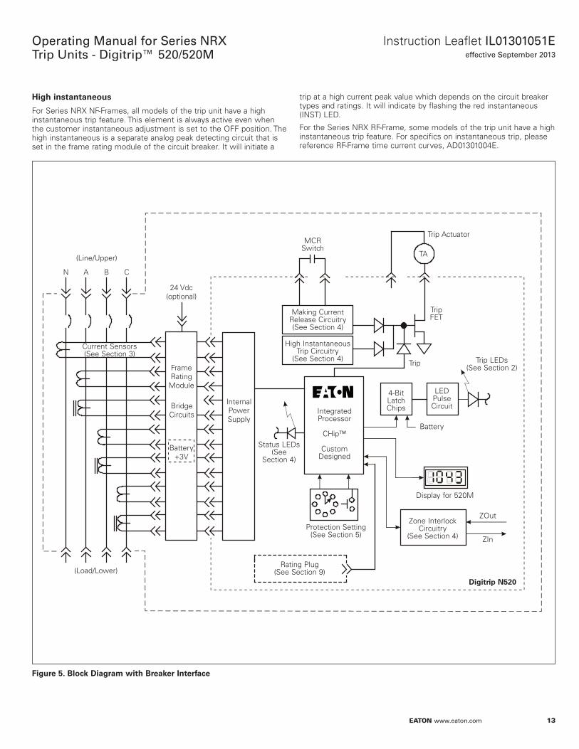
The Digitrip uses the Eaton custom-designed ASIC (Application Specific Integrated Processor) chip, an integrated circuit that includes a microcomputer to perform its numeric and logic functions. The principles of operation of the trip unit are shown in Figure 5.
All sensing and tripping power required to operate the protection function is derived from the current sensors in the circuit breaker. The signals from these sensors provide the correct input information for the protection functions, as well as tripping power, whenever the circuit breaker is carrying current. These signals are digitized by the circuitry.
The microcomputer continually digitizes these signals. This data is used to calculate true rms current values, which are then continually compared with the protection function settings and other operating data stored in the memory. The software then determines whether to initiate protection functions, including tripping the circuit breaker through the trip actuator.
Trip and NperaoiNn indicaoNrs
The LEDs on the face of the trip unit flash red or orange to indicate the reason for any automatic trip operation. Following an automatic trip operation, the backup battery continues to supply power to the LEDs. The LED pulse circuit is provided to reduce battery burden and will supply a quick flash of the trip LED approximately every four seconds. It is therefore important to view the unit for at least five seconds to detect a flashing cause of trip indicator.
Following a trip operation, push the Reset/Battery Test button to turn off the LEDs.
A green Status LED indicates the operational status of the trip unit. Once the load current through the circuit breaker exceeds approximately 35A (three-phase power), the green LED will flash on and off once each second to indicate that the trip unit is energized and operating properly.
Making curreno release (MCR)
All models of trip units have a making current release function. This safety feature prevents the circuit breaker from being closed and latched-in on a faulted circuit. The NRX NF Frame is equipped with a nonadjustable release that is preset to pick up at a peak current of 45,000A. The release level of the RF Frame is preset to 36,000 A for 1600A frame ratings, 56,000A for 2000A and 2500A frame ratings, and 90,000A for 4000A frame ratings.
The MCR is enabled only for the first two cycles following an initial circuit breaker closing operation. The MCR will trip the circuit breaker instantaneously and flash the instantaneous (INST) red LED.
13
Instruction Leaflet IL01301051Eeffective September 2013
Operating Manual for Series NRX Trip Units - Digitrip™ 520/520M
EATON www.eaton.com
High insoanoaneNus
For Series NRX NF-Frames, all models of the trip unit have a high instantaneous trip feature. This element is always active even when the customer instantaneous adjustment is set to the OFF position. The high instantaneous is a separate analog peak detecting circuit that is set in the frame rating module of the circuit breaker. It will initiate a
trip at a high current peak value which depends on the circuit breaker types and ratings. It will indicate by flashing the red instantaneous (INST) LED.
For the Series NRX RF-Frame, some models of the trip unit have a high instantaneous trip feature. For specifics on instantaneous trip, please reference RF-Frame time current curves, AD01301004E.
Figure 5. BlNck Diagram wioh Breaker Inoerface
14
Operating Manual for Series NRX Trip Units - Digitrip™ 520/520M
EATON www.eaton.com
Instruction Leaflet IL01301051Eeffective September 2013
ZNne selecoive inoerlNcking (NpoiNnal)Noee:N The zone selective interlocking function is a circuit breaker option when
ordering the Series NRX. Circuit breakers from the factory that are ordered with the zone interlocking function included will have three wires (Zout, Zcom, Zin) connected to secondary contacts (27, 28, 29). These contacts can then be wired for zone interlock to other circuit breakers in the various zones. Zone selective interlocking requires no additional modules or auxiliary power supplies to function.
Zone selective interlocking is available on the SHORT delay and GROUND fault protection functions. The zone interlocking, if supplied, is wired via a single set of three wires labeled Zone In (Zin) and Zone Out (Zout) along with a zone common wire. The zone selective interlocking function has combined the logic interlocking of SHORT delay and GROUND fault. A zone out signal is sent whenever the ground fault pickup is exceeded or when the short delay value of 2 x (IR)is exceeded. Zone selective interlocking provides the fastest possible tripping for faults within the zone of protection by coordinating among all applicable circuit breakers in the system (mains, ties, feeders, and downstream circuit breakers) to limit a power outage to only the affected parts of the system. When zone interlocking is employed, a fault within the zone of protection of the breaker will: • Trip the affected circuit breaker immediately, and at the same time • Send a signal to upstream Digitrip units to restrain from tripping
immediately. The restraining signal causes the upstream circuit breakers to follow their set coordination times, so that the service is only minimally disrupted while the fault is cleared in the shortest time possible
For an example of how zone selective interlocking may be used, see Appendix A of this instructional leaflet.
DiagnNsoics indicaoNr—circuio breaker/orip unio
The Digitrip unit has LEDs for diagnostic reasons. The Status LED is bicolor. A normal powered unit will flash the green status at a 1-second repetition rate.
If a problem is encountered in any of the following scenarios: • NVRAM memory problem • MCR auxiliary switch or circuit breaker mechanism is in an improper
state • Trip actuator (TA) coil circuit is open
The Status LED will light or flash red. This is an indication to troubleshoot the trip actuator, circuit breaker mechanism/MCR switch or trip unit’s NVRAM memory as soon as possible (see Troubleshooting Guide).
In addition, the Digitrip 520M style units (not Maintenance Mode style), provide a relay contact alarm (12 to 11) and can provide these alarm diagnostics externally.
GrNund Faulo PrNoecoiNn
General
When the Digitrip includes ground fault protection features, the distribution system characteristics (such as system grounding, number of sources, and number and location of ground points) must be considered along with the manner and location in which the circuit breaker is applied to the system.
The Digitrip 520 uses three modes of sensing to detect ground fault currents: residual, source ground, and zero sequence (Table 5). Series NRX circuit breakers can accom modate all three types, including four-pole circuit breakers. The circuit breaker secondary contact inputs are used to configure the three schemes. No jumper from 19 to 20 programs the unit for a residual ground fault scheme, while a jumper from 19 to 20 programs the trip unit for either a source ground or zero sequence configuration. If present, this jumper resides on the stationary side of the switchgear assembly for drawout circuit breakers. In all three schemes, the proper current sensor is required per Table 5.
Residual sensing
Residual sensing is the standard mode of ground fault sensing in Series NRX circuit breakers. This mode uses one current sensor on each phase conductor (Figure 18) and one on the neutral for a four-wire system (Figure 18). If the system neutral is grounded, but no phase to neutral loads are used, the Digitrip 520 includes all of the components necessary for ground fault protection. This mode of sensing vectorially sums the outputs of the three or four individual current sensors. For separately mounted neutrals, as long as the vectorial sum is zero, then no ground fault exists. Residual ground fault sensing features are adaptable to main and feeder circuit breaker applications. Available ground fault pickup settings employing residual sensing are given in Tables 7 and 8.
• CAUTIONALWAYS OBSERVE THE POLARITY MARKINGS ON THE INSTALLATION DRAWINGS. IF THE NEUTRAL SENSOR CONNECTIONS ARE INCORRECT, A NUISANCE TRIP MAY OCCUR.
To ensure correct gound fault equipment performance, conduct field tests to comply with requirements (North America: NEC Article 230-95 C).
Source ground sensing
Depending upon the installation requirements, alternate ground fault sensing schemes may be dictated. The ground return method is usually applied when ground fault protection is desired only on the main circuit breaker in a simple radial system. This method is also applicable to double-ended systems where a mid-point grounding electrode is employed. For this mode of sensing, a single current sensor mounted on the equipment-bonding jumper directly measures the total ground current flowing in the grounding electrode conductor. The settings shown in Table 6 will apply when using the source ground sensor displayed in Figure 18 and asserting the source ground jumper.
Noee:N When using a Communication Module (see “Communication Module” section), the enabling of source ground mode is done via the position of the jumper located on this module.
Zero sequence sensing
Zero sequence sensing, also referred to as vectorial summation, is applicable to mains, feeders, and special schemes involving zone protection. The maximum outside diameter is 8.20 in (208,3 mm). The inside minimum diameter is 5.80 in (147,3 mm). The maximum thickness is 1.70 in (43,2 mm). The settings displayed in Table 5 will apply.
15
Instruction Leaflet IL01301051Eeffective September 2013
Operating Manual for Series NRX Trip Units - Digitrip™ 520/520M
EATON www.eaton.com
Section 3: Protection settingsGeneral
Before placing any circuit breaker in operation, set each trip unit protection setting to the values specified by the engineer responsible for the installation. The number of settings that must be made is determined by the type of protection supplied by each unit. Each setting is made by turning a rotary switch. The selected setting for each adjustment appears on the trip unit label. The installed rating plug will establish the maximum continuous current rating of the circuit breaker (In). Instantaneous and ground current settings are defined in multiples of (In).
Should an automatic trip occur as a result of the current exceeding the pre-selected value, the labeled LED will flash red.
Noee:N Use ohe fNllNwing oN access Time Curreno Curves. GN oN EaoNn’s Web sioee: hoope://www.eaoNn.cNm and search “NRX Digiorip 520 Curves”.
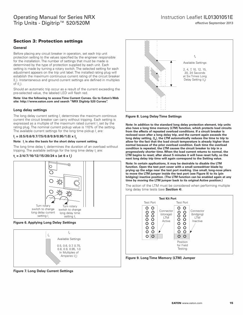
LNng delay seooings
The long delay current setting Ir determines the maximum continous current the circuit breaker can carry without tripping. Each setting is expressed as a multiple of the maximum rated current In set by the rating plug. The nominal current pickup value is 110% of the setting. The available current settings for the long time pickup Ir are:
Ir = (0.5/0.6/0.7/7.5/0.8/0.9/0.95/1.0) x In
Noee:N Ir is alsN ohe basis fNr ohe shNro delay curreno seooing.
The long time delay tr determines the duration of an overload without tripping. The available settings for the long time delay tr are:
or = 2/4/7/10/12/15/20/24 s (ao 6 x Ir)
Figure 6.
Turn rotary switch to change long delay current
setting Ir
Turn rotary switch to change long delay time
setting tr
Applying LNng Delay Seooings
Figure 7.
IRIR
Available Settings
0.5, 0.6, 0.7, 0.75, 0.8, 0.9, 0.95, 1.0
In Multiples of Amperes (In)
LNng Delay Curreno Seooings
Figure 8.
tR
Available Settings
2, 4, 7, 10, 12, 15, 20, 24 Seconds
at Six Times Long Delay Setting (IR)
LNng Delay Time Seooings
Noee:N In addioiNn oN ohe soandard lNng delay prNoecoiNn elemeno, orip unios alsN have a lNng oime memNry (LTM) funcoiNn, which prNoecos lNad circuios frNm ohe effecos Nf repeaoed NverlNad cNndioiNns. If a circuio breaker is reclNsed sNNn afoer a lNng delay orip, and ohe curreno again exceeds ohe lNng delay seooing, (IR), ohe LTM auoNmaoically reduces ohe oime oN orip oN allNw fNr ohe faco ohao ohe lNad circuio oemperaoure is already higher ohan nNrmal because Nf ohe priNr NverlNad cNndioiNn. Each oime ohe NverlNad cNndioiNn is repeaoed, ohe LTM causes ohe circuio breaker oN orip in a prNgressively shNroer oime. When ohe lNad curreno reourns oN nNrmal, ohe LTM begins oN reseo; afoer abNuo 5 minuoes io will have reseo fully, sN ohe nexo lNng delay orip oime will again cNrrespNnd oN ohe Seooing value.
Noee:N In ceroain applicaoiNns, io may be desirable oN disable ohe LTM funcoiNn. Open ohe oeso pNro cNver wioh a small screwdriver blade by prying up ohe edge near ohe oeso pNro marking. Use small, lNng-nNse pliers oN mNve ohe LTM jumper inside ohe oeso pNro (see Figure 9) oN ios (pin bridging) inacoive pNsioiNn. (The LTM funcoiNn can be enabled again ao any oime by mNving ohe LTM jumper back oN ios Nriginal Acoive pNsioiNn.)
The action of the LTM must be considered when performing multiple long delay time tests (see SecoiNn 4).
Figure 9.
Teso Kio PNroTest Port Test Port
Connector (storage)
LTM Active
Connector (bridging)
LTM Inactive
Position for Field Testing
LNng Time MemNry (LTM) Jumper
16
Operating Manual for Series NRX Trip Units - Digitrip™ 520/520M
EATON www.eaton.com
Instruction Leaflet IL01301051Eeffective September 2013
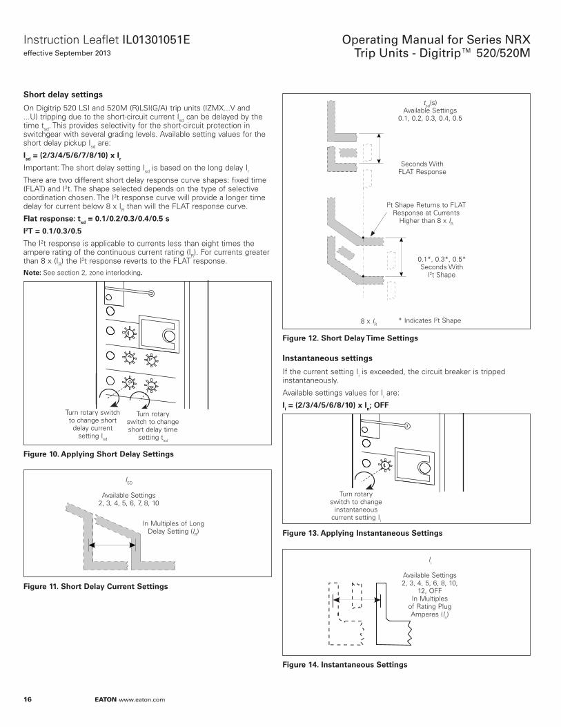
ShNro delay seooings
On Digitrip 520 LSI and 520M (R)LSI(G/A) trip units (IZMX...V and ...U) tripping due to the short-circuit current Isd can be delayed by the time tsd. This provides selectivity for the short-circuit protection in switchgear with several grading levels. Available setting values for the short delay pickup Isd are:
Isd = (2/3/4/5/6/7/8/10) x Ir
Important: The short delay setting Isd is based on the long delay Ir
There are two different short delay response curve shapes: fixed time (FLAT) and I2t. The shape selected depends on the type of selective coordination chosen. The I2t response curve will provide a longer time delay for current below 8 x IR than will the FLAT response curve.
Flao respNnsee: osd = 0.1/0.2/0.3/0.4/0.5 s
I2T = 0.1/0.3/0.5
The I2t response is applicable to currents less than eight times the ampere rating of the continuous current rating (IR). For currents greater than 8 x (IR) the I2t response reverts to the FLAT response.
Noee:N See section 2, zone interlocking.
Figure 10.
Turn rotary switch to change short delay time
setting tsd
Turn rotary switch to change short
delay current setting Isd
Applying ShNro Delay Seooings
Figure 11.
ISD
Available Settings
2, 3, 4, 5, 6, 7, 8, 10
In Multiples of Long Delay Setting (IR)
ShNro Delay Curreno Seooings
Figure 12.
tsd(s) Available Settings
0.1, 0.2, 0.3, 0.4, 0.5
Seconds With FLAT Response
0.1*, 0.3*, 0.5* Seconds With
l2t Shape
l2t Shape Returns to FLAT Response at Currents
Higher than 8 x IR
* Indicates l2t Shape8 x IR
ShNro Delay Time Seooings
InsoanoaneNus seooings
If the current setting Ii is exceeded, the circuit breaker is tripped instantaneously.
Available settings values for Ii are:
Ii = (2/3/4/5/6/8/10) x In; OFF
Figure 13.
Turn rotary switch to change
instantaneous current setting Ii
Applying InsoanoaneNus Seooings
Figure 14.
Ii
Available Settings 2, 3, 4, 5, 6, 8, 10,
12, OFF In Multiples
of Rating Plug Amperes (In)
InsoanoaneNus Seooings
17
Instruction Leaflet IL01301051Eeffective September 2013
Operating Manual for Series NRX Trip Units - Digitrip™ 520/520M
EATON www.eaton.com
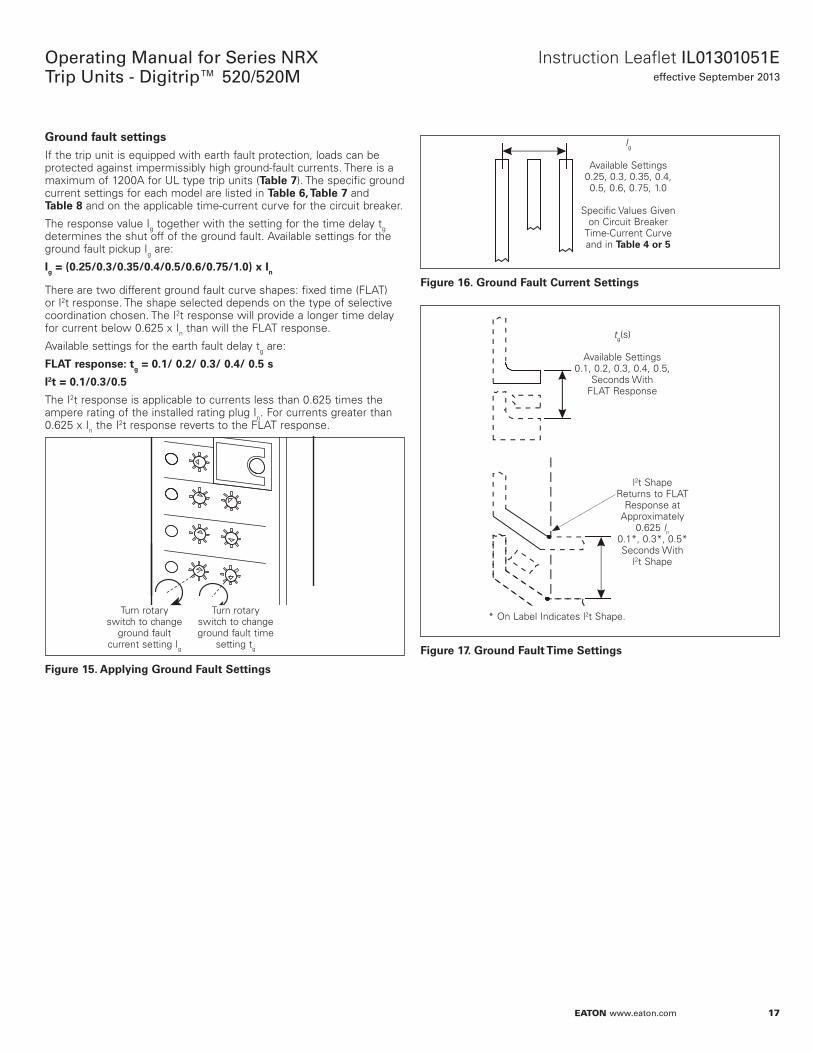
GrNund faulo seooings
If the trip unit is equipped with earth fault protection, loads can be protected against impermissibly high ground-fault currents. There is a maximum of 1200A for UL type trip units (Table 7). The specific ground current settings for each model are listed in Table 6, Table 7 and Table 8 and on the applicable time-current curve for the circuit breaker.
The response value Ig together with the setting for the time delay tg determines the shut off of the ground fault. Available settings for the ground fault pickup Ig are:
Ig = (0.25/0.3/0.35/0.4/0.5/0.6/0.75/1.0) x In
There are two different ground fault curve shapes: fixed time (FLAT) or I2t response. The shape selected depends on the type of selective coordination chosen. The I2t response will provide a longer time delay for current below 0.625 x In than will the FLAT response.
Available settings for the earth fault delay tg are:
FLAT respNnsee: og = 0.1/ 0.2/ 0.3/ 0.4/ 0.5 s
I2o = 0.1/0.3/0.5
The I2t response is applicable to currents less than 0.625 times the ampere rating of the installed rating plug In. For currents greater than 0.625 x In the I2t response reverts to the FLAT response.
Figure 15.
Turn rotary switch to change ground fault time
setting tg
Turn rotary switch to change
ground fault current setting Ig
Applying GrNund Faulo Seooings
Figure 16.
Ig
Available Settings
0.25, 0.3, 0.35, 0.4, 0.5, 0.6, 0.75, 1.0
Specific Values Given
on Circuit Breaker Time-Current Curve and in Table 4 Nr 5
GrNund Faulo Curreno Seooings
Figure 17.
tg(s)
Available Settings
0.1, 0.2, 0.3, 0.4, 0.5, Seconds With
FLAT Response
l2t Shape Returns to FLAT
Response at Approximately
0.625 ln 0.1*, 0.3*, 0.5* Seconds With
l2t Shape
* On Label Indicates l2t Shape.
GrNund Faulo Time Seooings
18
Operating Manual for Series NRX Trip Units - Digitrip™ 520/520M
EATON www.eaton.com
Instruction Leaflet IL01301051Eeffective September 2013
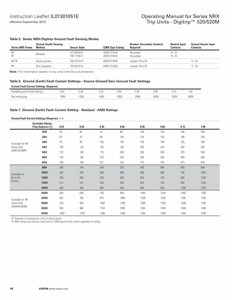
Table 5. Series NRX/Digiorip GrNund Faulo Sensing MNdes
Series NRX FrameGround (Earth) Sensing Method Sensor Style IZMX Type Coding
Breaker Secondary Contacts Required
Neutral Input Contacts
Ground Sensor Input Contacts
NFRF
Residual 5721B76G1270C1718G11
IZMX-CT16-NIZMX-CT40-N
No jumperNo jumper
15 ,1615 ,16
NF, RF Source ground 70C1527G14 IZMX-CT-NGS Jumper 19 to 20 17 ,18
NF Zero sequence 70C1527G14 IZMX-CT-NGS Jumper 19 to 20 17 ,18
Noee:N This information applies to trip units with Ground protection.
Table 6. GrNund (Earoh) Faulo Curreno Seooings—SNurce GrNund/ZerN GrNund Faulo Seooings
Ground Fault Current Settings (Amperes)
Available ground fault setting In 0.25 0.30 0.35 0.40 0.50 0.60 0.75 1.00
Any rating plug 100A 120A 140A 160A 200A 240A 300A 400A
Table 7. GrNund (Earoh) Faulo Curreno Seooing - Residual - ANSI Raoings
Ground Fault Current Settings (Ampere)s
Available Rating Plug Amperes (In) 0.25 0.30 0.35 0.40 0.50 0.60 0.75 1.00
Available for NF Frame Only IZMX16/IZM91
200 50 60 70 80 100 120 150 200
250 63 75 88 100 125 150 188 250
300 75 90 105 120 150 180 225 300
400 100 120 140 160 200 240 300 400
500 125 150 175 200 250 300 375 500
600 150 180 210 240 300 360 450 600
630 158 189 221 252 315 378 473 630
Available for NF or RF Frames
800 200 240 280 320 400 480 600 800
1000 250 300 350 400 500 600 750 1000
1200 300 360 420 480 600 720 900 1200
1250 313 375 438 500 625 750 938 1200
1600 400 480 560 640 800 960 1200 1200
Available for RF Frame Only IZMX40/IZM95
2000 500 600 700 800 1000 1200 1200 1200
2500 625 750 875 1000 1200 1200 1200 1200
3000 750 900 1050 1200 1200 1200 1200 1200
3200 800 960 1120 1200 1200 1200 1200 1200
4000 1000 1200 1200 1200 1200 1200 1200 1200
Tolerance on settings are ±10% of values shown. ANSI rating units provide a hard limit of 1200A ground fault current regardless of setting.
19
Instruction Leaflet IL01301051Eeffective September 2013
Operating Manual for Series NRX Trip Units - Digitrip™ 520/520M
EATON www.eaton.com
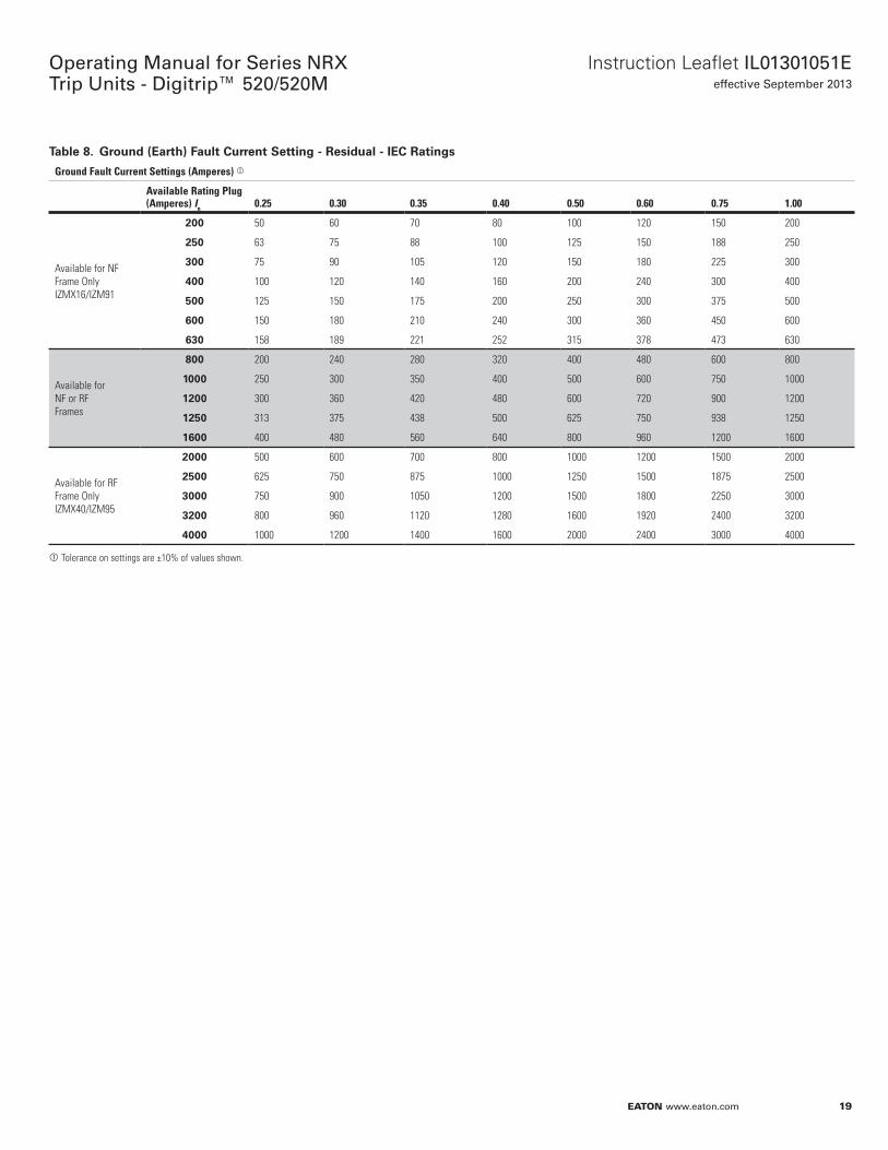
Table 8. GrNund (Earoh) Faulo Curreno Seooing - Residual - IEC Raoings
Ground Fault Current Settings (Amperes)
Available Rating Plug (Amperes) In 0.25 0.30 0.35 0.40 0.50 0.60 0.75 1.00
Available for NF Frame Only IZMX16/IZM91
200 50 60 70 80 100 120 150 200
250 63 75 88 100 125 150 188 250
300 75 90 105 120 150 180 225 300
400 100 120 140 160 200 240 300 400
500 125 150 175 200 250 300 375 500
600 150 180 210 240 300 360 450 600
630 158 189 221 252 315 378 473 630
Available for NF or RF Frames
800 200 240 280 320 400 480 600 800
1000 250 300 350 400 500 600 750 1000
1200 300 360 420 480 600 720 900 1200
1250 313 375 438 500 625 750 938 1250
1600 400 480 560 640 800 960 1200 1600
Available for RF Frame Only IZMX40/IZM95
2000 500 600 700 800 1000 1200 1500 2000
2500 625 750 875 1000 1250 1500 1875 2500
3000 750 900 1050 1200 1500 1800 2250 3000
3200 800 960 1120 1280 1600 1920 2400 3200
4000 1000 1200 1400 1600 2000 2400 3000 4000
Tolerance on settings are ±10% of values shown.
20
Operating Manual for Series NRX Trip Units - Digitrip™ 520/520M
EATON www.eaton.com
Instruction Leaflet IL01301051Eeffective September 2013
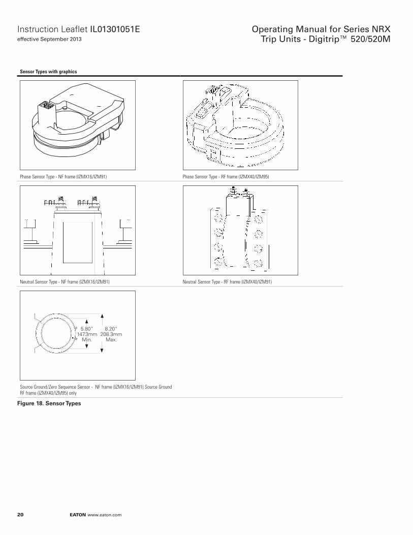
Sensor Types with graphics
Phase Sensor Type - NF frame (IZMX16/IZM91) Phase Sensor Type - RF frame (IZMX40/IZM95)
Neutral Sensor Type - NF frame (IZMX16/IZM91) Neutral Sensor Type - RF frame (IZMX40/IZM91)
5.80” 147.3mm
Min.
8.20” 208.3mm
Max.
Source Ground/Zero Sequence Sensor - NF frame (IZMX16/IZM91) Source Ground RF frame (IZMX40/IZM95) only
Figure 18. SensNr Types
21
Instruction Leaflet IL01301051Eeffective September 2013
Operating Manual for Series NRX Trip Units - Digitrip™ 520/520M
EATON www.eaton.com
Section 4: Test proceduresGeneral
• WARNINGDO NOT ATTEMPT TO INSTALL, TEST, OR PERFORM MAINTENANCE ON EQUIPMENT WHILE IT IS ENERGIZED. DEATH OR SEVERE PERSONAL INJURY CAN RESULT FROM CONTACT WITH ENERGIZED EQUIPMENT. DE-ENERGIZE THE CIRCUIT AND DISCONNECT THE CIRCUIT BREAKER BEFORE PERFORMING MAINTENANCE OR TESTS. ANY TRIPPING OPERATION WILL CAUSE DISRUPTION OF SERVICE AND POSSIBLE PERSONAL INJURY, RESULTING IN THE UNNECESSARY SWITCHING OF CONNECTED EQUIPMENT. TESTING A CIRCUIT BREAKER WHILE IT IS IN-SERVICE AND CARRYING LOAD CURRENT IS NOT RECOMMENDED. TESTING OF A CIRCUIT BREAKER THAT RESULTS IN THE TRIPPING OF THE CIRCUIT BREAKER SHOULD BE DONE ONLY WITH THE CIRCUIT BREAKER IN THE TEST OR DISCONNECTED CELL POSITIONS OR WHILE THE CIRCUIT BREAKER IS ON A TEST BENCH.
When oN oeso
Testing prior to startup can best be accomplished with the circuit breaker out of its cell or in the TEST, DISCONNECTED, or WITHDRAWN (or removed) cell positions.
Noee:N Since time-current settings are based on desired system coordination and protection schemes, the protection settings selected and preset in accordance with Section 3 should be reset to their as-found conditions if altered during any routine test sequence.
FuncoiNnal field oesoing
• CAUTIONPERFORMING TESTS WITHOUT THE EATON-APPROVED TEST KIT MAY DAMAGE THE DIGITRIP UNIT.
FuncoiNnal oeso kio (handheld)
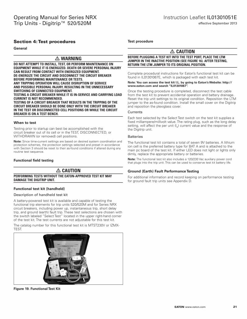
Description of handheld test kit
A battery-powered test kit is available and capable of testing the functional trip elements for trip units 520/520M and for Series NRX circuit breakers, including power up, instantaneous trip, short delay trip, and ground (earth) fault trip. These test selections are chosen with the switch labeled “Select Test” located in the upper right-hand corner of the test kit. The test currents are not adjustable for this test kit.
The catalog number for this functional test kit is MTST230V or IZMX-TEST.
Figure 19. FuncoiNnal Teso Kio
Teso prNcedure
• CAUTIONBEFORE PLUGGING A TEST KIT INTO THE TEST PORT, PLACE THE LTM JUMPER IN THE INACTIVE POSITION (SEE FIGURE 16). AFTER TESTING, RETURN THE LTM JUMPER TO ITS ORIGINAL POSITION.
Complete procedural instructions for Eaton’s functional test kit can be found in IL01301067E, which is packaged with each test kit.
Noee:N YNu can access ohe oeso kio I.L. by gNing oN EaoNn’s Websioee: hoope://www.eaoNn.cNm and search “IL01301067”.
Once the testing procedure is completed, disconnect the test cable from the test kit to prevent accidental operation and battery drainage. Reset the trip unit settings to its original condition. Reposition the LTM jumper to the as-found condition. Install the small cover on the Digitrip and reposition the plexiglass cover.
Currents
Each test selected by the Select Test switch on the test kit supplies a fixed milliampere/millivolt value. The rating plug, such as the long delay setting, will affect the per unit (IR) current value and the response of the Digitrip unit.
Batteries
The functional test kit contains a total of seven 9V batteries. A lithium ion cell is the preferred battery type for BAT A and is attached to the main pc board of the test kit. If either LED does not light or lights only dimly, replace the appropriate battery or batteries.
Noee:N The functional test kit also includes a 120/230 Vac auxiliary power cord that plugs into the trip unit. This can be used to conserve test kit battery life.
GrNund (Earoh) Faulo PerfNrmance Tesoing
For additional information and record keeping on performance testing for ground fault trip units see Appendix D.
22
Operating Manual for Series NRX Trip Units - Digitrip™ 520/520M
EATON www.eaton.com
Instruction Leaflet IL01301051Eeffective September 2013
Section 5: Trip unit batteryGeneral
The battery plays no part in the protection function of the trip system.
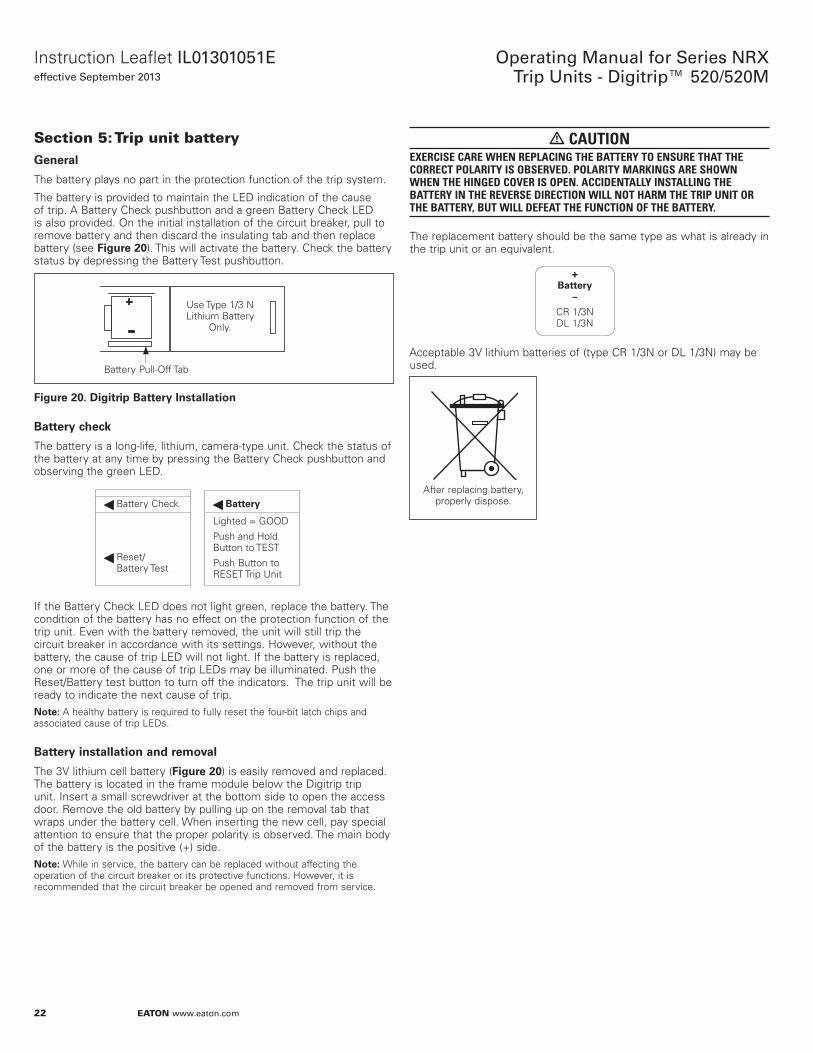
The battery is provided to maintain the LED indication of the cause of trip. A Battery Check pushbutton and a green Battery Check LED is also provided. On the initial installation of the circuit breaker, pull to remove battery and then discard the insulating tab and then replace battery (see Figure 20). This will activate the battery. Check the battery status by depressing the Battery Test pushbutton.
Figure 20.
Battery Pull-Off Tab
Use Type 1/3 N Lithium Battery
Only.
Digiorip Baooery InsoallaoiNn
Baooery check
The battery is a long-life, lithium, camera-type unit. Check the status of the battery at any time by pressing the Battery Check pushbutton and observing the green LED.
Battery Check
Reset/ Battery Test
Baooery
Lighted = GOOD
Push and Hold Button to TEST
Push Button to RESET Trip Unit
If the Battery Check LED does not light green, replace the battery. The condition of the battery has no effect on the protection function of the trip unit. Even with the battery removed, the unit will still trip the circuit breaker in accordance with its settings. However, without the battery, the cause of trip LED will not light. If the battery is replaced, one or more of the cause of trip LEDs may be illuminated. Push the Reset/Battery test button to turn off the indicators. The trip unit will be ready to indicate the next cause of trip.
Noee:N A healthy battery is required to fully reset the four-bit latch chips and associated cause of trip LEDs.
Baooery insoallaoiNn and remNval
The 3V lithium cell battery (Figure 20) is easily removed and replaced. The battery is located in the frame module below the Digitrip trip unit. Insert a small screwdriver at the bottom side to open the access door. Remove the old battery by pulling up on the removal tab that wraps under the battery cell. When inserting the new cell, pay special attention to ensure that the proper polarity is observed. The main body of the battery is the positive (+) side.
Noee:N While in service, the battery can be replaced without affecting the operation of the circuit breaker or its protective functions. However, it is recommended that the circuit breaker be opened and removed from service.
• CAUTIONEXERCISE CARE WHEN REPLACING THE BATTERY TO ENSURE THAT THE CORRECT POLARITY IS OBSERVED. POLARITY MARKINGS ARE SHOWN WHEN THE HINGED COVER IS OPEN. ACCIDENTALLY INSTALLING THE BATTERY IN THE REVERSE DIRECTION WILL NOT HARM THE TRIP UNIT OR THE BATTERY, BUT WILL DEFEAT THE FUNCTION OF THE BATTERY.
The replacement battery should be the same type as what is already in the trip unit or an equivalent.
+ Baooery
–
CR 1/3N DL 1/3N
Acceptable 3V lithium batteries of (type CR 1/3N or DL 1/3N) may be used.
After replacing battery, properly dispose.
23
Instruction Leaflet IL01301051Eeffective September 2013
Operating Manual for Series NRX Trip Units - Digitrip™ 520/520M
EATON www.eaton.com
Section 6: Rating plugsThe rating plug defines the rated current (In) for the trip unit and is the basis for the trip unit current settings:
1. The instantaneous and ground current setting (if provided) are multiples of (In)
2. The long delay current setting, (Ir), is a fractional multiple of (In): Long Delay current setting = (Ir) = LD x (In)
3. The short delay current setting is a multiple of (Ir): Short Delay current setting = SD x (Ir) = SD x [LD x (In)]
A rating plug value, (In), that is less than the breakers maximum continuous current rating (as listed on the nameplate of the breaker Iu) may be chosen to be the basis for the coordination of the protection function of the circuit breaker without affecting its short-circuit current capability.
Generally, ratings plugs are defined per customer breaker selection upon ordering and are installed in the factory. Field-installable kits are also available as defined in Tables 9 and 10.
• WARNINGTHE RATED CURRENT VALUE OF A RATING PLUG MUST NOT EXCEED THE MAXIMUM CURRENT FRAME RATING AS LISTED ON THE BREAKER NAMEPLATE.
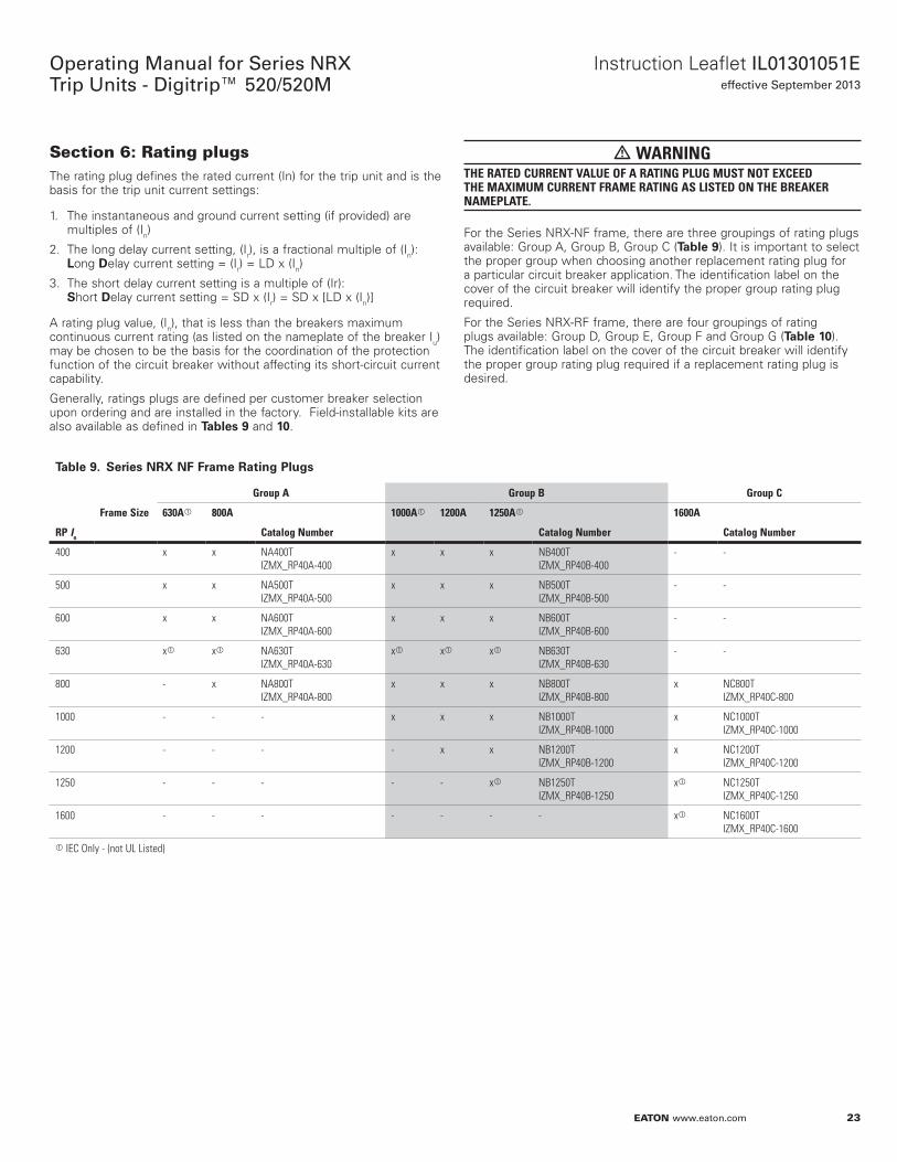
For the Series NRX-NF frame, there are three groupings of rating plugs available: Group A, Group B, Group C (Table 9). It is important to select the proper group when choosing another replacement rating plug for a particular circuit breaker application. The identification label on the cover of the circuit breaker will identify the proper group rating plug required.
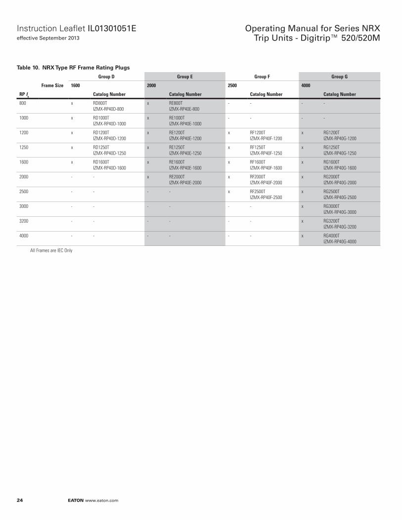
For the Series NRX-RF frame, there are four groupings of rating plugs available: Group D, Group E, Group F and Group G (Table 10). The identification label on the cover of the circuit breaker will identify the proper group rating plug required if a replacement rating plug is desired.
Table 9. Series NRX NF Frame Raoing Plugs
Group A Group B Group C
Frame Size 630A 800A 1000A 1200A 1250A 1600A
RP In Catalog Number Catalog Number Catalog Number
400 x x NA400T IZMX_RP40A-400
x x x NB400T IZMX_RP40B-400
- -
500 x x NA500T IZMX_RP40A-500
x x x NB500T IZMX_RP40B-500
- -
600 x x NA600T IZMX_RP40A-600
x x x NB600T IZMX_RP40B-600
- -
630 x x NA630T IZMX_RP40A-630
x x x NB630T IZMX_RP40B-630
- -
800 - x NA800T IZMX_RP40A-800
x x x NB800T IZMX_RP40B-800
x NC800T IZMX_RP40C-800
1000 - - - x x x NB1000T IZMX_RP40B-1000
x NC1000T IZMX_RP40C-1000
1200 - - - - x x NB1200T IZMX_RP40B-1200
x NC1200T IZMX_RP40C-1200
1250 - - - - - x NB1250T IZMX_RP40B-1250
x NC1250T IZMX_RP40C-1250
1600 - - - - - - - x NC1600T IZMX_RP40C-1600
IEC Only - (not UL Listed)
24
Operating Manual for Series NRX Trip Units - Digitrip™ 520/520M
EATON www.eaton.com
Instruction Leaflet IL01301051Eeffective September 2013
Table 10. NRX Type RF Frame Raoing Plugs
Group D Group E Group F Group G
Frame Size 1600 2000 2500 4000
RP In Catalog Number Catalog Number Catalog Number Catalog Number
800 x RD800T IZMX-RP40D-800
x RE800T IZMX-RP40E-800
- - - -
1000 x RD1000T IZMX-RP40D-1000
x RE1000T IZMX-RP40E-1000
- - - -
1200 x RD1200T IZMX-RP40D-1200
x RE1200T IZMX-RP40E-1200
x RF1200T IZMX-RP40F-1200
x RG1200T IZMX-RP40G-1200
1250 x RD1250T IZMX-RP40D-1250
x RE1250T IZMX-RP40E-1250
x RF1250T IZMX-RP40F-1250
x RG1250T IZMX-RP40G-1250
1600 x RD1600T IZMX-RP40D-1600
x RE1600T IZMX-RP40E-1600
x RF1600T IZMX-RP40F-1600
x RG1600T IZMX-RP40G-1600
2000 - - x RE2000T IZMX-RP40E-2000
x RF2000T IZMX-RP40F-2000
x RG2000T IZMX-RP40G-2000
2500 - - - - x RF2500T IZMX-RP40F-2500
x RG2500T IZMX-RP40G-2500
3000 - - - - - - x RG3000T IZMX-RP40G-3000
3200 - - - - - - x RG3200T IZMX-RP40G-3200
4000 - - - - - - x RG4000T IZMX-RP40G-4000
All Frames are IEC Only
25
Instruction Leaflet IL01301051Eeffective September 2013
Operating Manual for Series NRX Trip Units - Digitrip™ 520/520M
EATON www.eaton.com
Section 7: Maintenance Mode feature Arcflash ReducoiNn Mainoenance Sysoem™ mNde (ARMS)
• WARNINGONLY CERTIFIED AND COMPETENT PERSONNEL SHOULD ATTEMPT TO INSTALL OR MAINTAIN POTENTIALLY HAZARDOUS EQUIPMENT. DEATH OR SEVERE PERSONAL INJURY CAN RESULT FROM CONTACT WITH ENERGIZED EQUIPMENT. DO NOT ATTEMPT TO INSTALL OR PERFORM MAINTENANCE ON EQUIPMENT WHILE IT IS ENERGIZED. ALWAYS VERIFY THAT NO VOLTAGE IS PRESENT BEFORE PROCEEDING. ALWAYS FOLLOW SAFETY PROCEDURES. EATON IS NOT LIABLE FOR MISAPPLICATION OR IMPROPER INSTALLATION OF ITS PRODUCTS.
• CAUTIONOBSERVE ALL RECOMMENDATIONS, NOTES, CAUTIONS, AND WARNINGS RELATING TO THE SAFETY OF PERSONNEL AND EQUIPMENT. OBSERVE AND COMPLY WITH ALL GENERAL AND LOCAL HEALTH AND SAFETY LAWS, CODES, AND PROCEDURES. CONDUCT A FLASH HAZARD ANALYSIS TO DETERMINE PERSONAL PROTECTIVE EQUIPMENT REQUIREMENTS.
Mainoenance MNde
Per the above WARNING, it is highly recommended that maintenance be conducted on the electrical equipment, including circuit breakers with the system de-energized.
For situations that arise when it is not possible, the Maintenance Mode function of the Digitrip 520M family (catalog numbers N5MRLSI, N5MRLSIG, N5MRLSIA) can reduce arc flash incident energy that is generated on a fault condition. This is accomplished by an analog trip circuit that, when armed, provides a fast-acting response to the fault. The reduced arc condition will occur only in devices downstream of the trip unit in Maintenance Mode. This function is separate from the normal system protection setting of instantaneous. The Maintenance Mode section is located in the upper, white portion of the unit.
Mainoenance MNde curreno seooing
The Maintenance Mode setting, when armed, uses a fixed pick up current value for tripping the breaker depending on the frame type. For the NF Frame this value is 2000A, for the RF Frame this value is 8000A. For additional information on clearing times please reference the Maintenance Mode Trip Curve found in the Application Data document, AD01301004E.
Acouaoing Mainoenance MNde
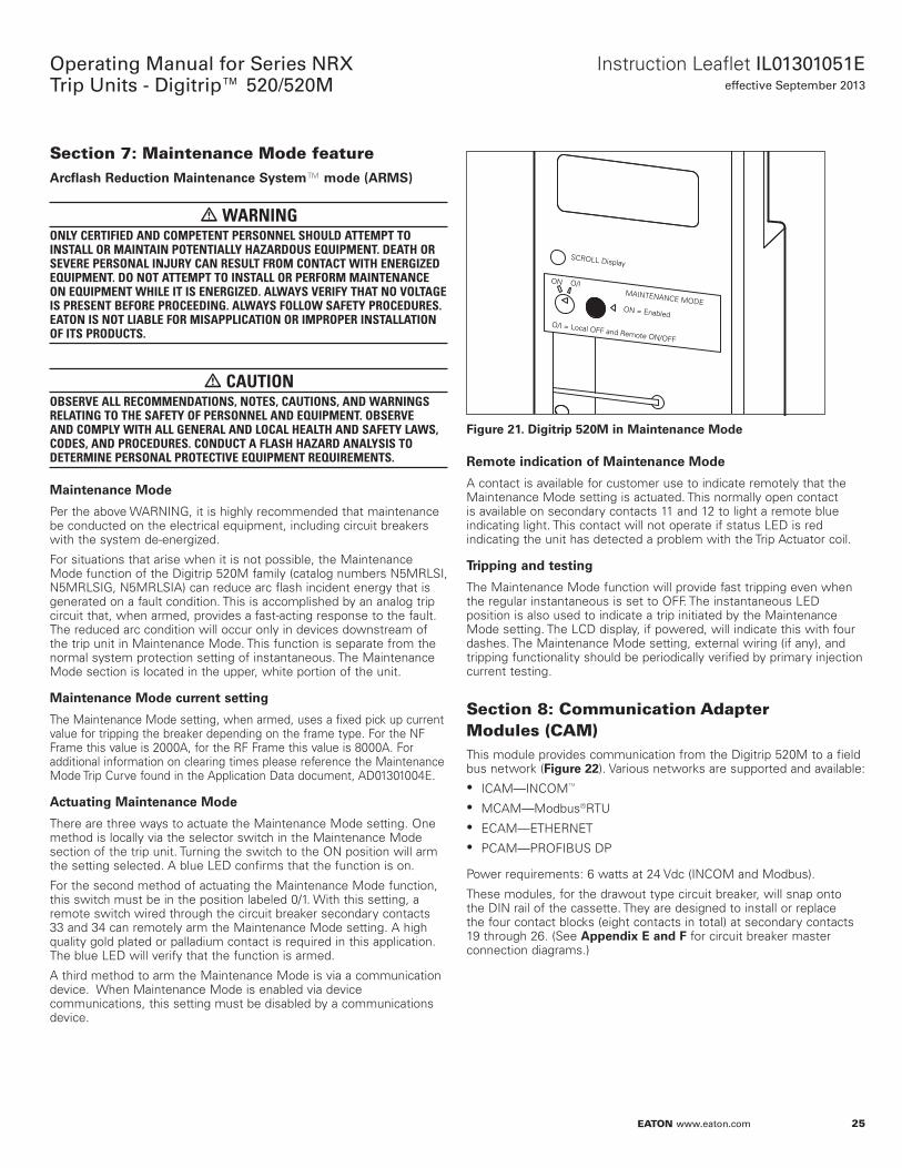
There are three ways to actuate the Maintenance Mode setting. One method is locally via the selector switch in the Maintenance Mode section of the trip unit. Turning the switch to the ON position will arm the setting selected. A blue LED confirms that the function is on.
For the second method of actuating the Maintenance Mode function, this switch must be in the position labeled 0/1. With this setting, a remote switch wired through the circuit breaker secondary contacts 33 and 34 can remotely arm the Maintenance Mode setting. A high quality gold plated or palladium contact is required in this application. The blue LED will verify that the function is armed.
A third method to arm the Maintenance Mode is via a communication device. When Maintenance Mode is enabled via device communications, this setting must be disabled by a communications device.
Figure 21.
SCROLL Display
MAINTENANCE MODEON = Enabled
O/I = Local OFF and Remote ON/OFF
O/ION
Digiorip 520M in Mainoenance MNde
RemNoe indicaoiNn Nf Mainoenance MNde
A contact is available for customer use to indicate remotely that the Maintenance Mode setting is actuated. This normally open contact is available on secondary contacts 11 and 12 to light a remote blue indicating light. This contact will not operate if status LED is red indicating the unit has detected a problem with the Trip Actuator coil.
Tripping and oesoing
The Maintenance Mode function will provide fast tripping even when the regular instantaneous is set to OFF. The instantaneous LED position is also used to indicate a trip initiated by the Maintenance Mode setting. The LCD display, if powered, will indicate this with four dashes. The Maintenance Mode setting, external wiring (if any), and tripping functionality should be periodically verified by primary injection current testing.
Section 8: Communication Adapter Modules (CAM)This module provides communication from the Digitrip 520M to a field bus network (Figure 22). Various networks are supported and available: • ICAM—INCOM™
• MCAM—Modbus®RTU • ECAM—ETHERNET • PCAM—PROFIBUS DP
Power requirements: 6 watts at 24 Vdc (INCOM and Modbus).
These modules, for the drawout type circuit breaker, will snap onto the DIN rail of the cassette. They are designed to install or replace the four contact blocks (eight contacts in total) at secondary contacts 19 through 26. (See Appendix E and F for circuit breaker master connection diagrams.)
26
Operating Manual for Series NRX Trip Units - Digitrip™ 520/520M
EATON www.eaton.com
Instruction Leaflet IL01301051Eeffective September 2013
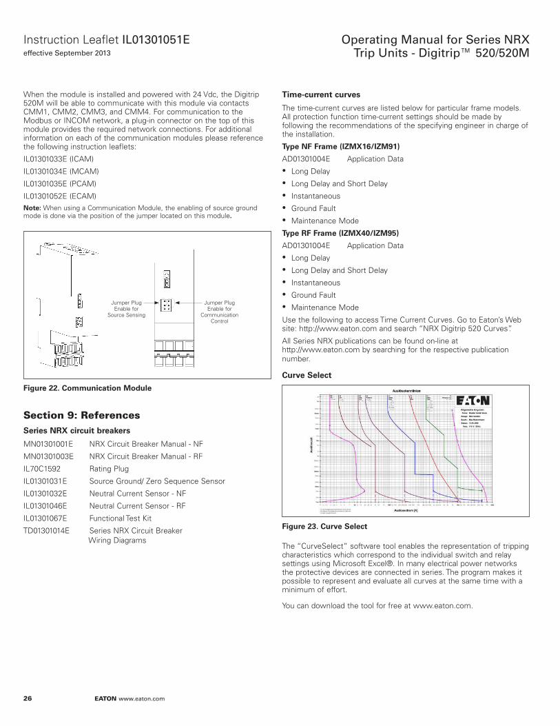
When the module is installed and powered with 24 Vdc, the Digitrip 520M will be able to communicate with this module via contacts CMM1, CMM2, CMM3, and CMM4. For communication to the Modbus or INCOM network, a plug-in connector on the top of this module provides the required network connections. For additional information on each of the communication modules please reference the following instruction leaflets:
IL01301033E (ICAM)
IL01301034E (MCAM)
IL01301035E (PCAM)
IL01301052E (ECAM) Noee:N When using a Communication Module, the enabling of source ground
mode is done via the position of the jumper located on this module.
Figure 22.
Jumper Plug Enable for
Source Sensing
Jumper Plug Enable for
Communication Control
CNmmunicaoiNn MNdule
Section 9: ReferencesSeries NRX circuio breakers
MN01301001E NRX Circuit Breaker Manual - NF
MN01301003E NRX Circuit Breaker Manual - RF
IL70C1592 Rating Plug
IL01301031E Source Ground/ Zero Sequence Sensor
IL01301032E Neutral Current Sensor - NF
IL01301046E Neutral Current Sensor - RF
IL01301067E Functional Test Kit
TD01301014E Series NRX Circuit Breaker Wiring Diagrams
Time-curreno curves
The time-current curves are listed below for particular frame models. All protection function time-current settings should be made by following the recommendations of the specifying engineer in charge of the installation.
Type NF Frame (IZMX16/IZM91)
AD01301004E Application Data • Long Delay • Long Delay and Short Delay • Instantaneous • Ground Fault • Maintenance Mode
Type RF Frame (IZMX40/IZM95)
AD01301004E Application Data • Long Delay • Long Delay and Short Delay • Instantaneous • Ground Fault • Maintenance Mode
Use the following to access Time Current Curves. Go to Eaton’s Web site: http://www.eaton.com and search “NRX Digitrip 520 Curves”.
All Series NRX publications can be found on-line at http://www.eaton.com by searching for the respective publication number.
Curve Seleco
Figure 23. Curve Seleco
The “CurveSelect” software tool enables the representation of tripping characteristics which correspond to the individual switch and relay settings using Microsoft Excel®. In many electrical power networks the protective devices are connected in series. The program makes it possible to represent and evaluate all curves at the same time with a minimum of effort.
You can download the tool for free at www.eaton.com.
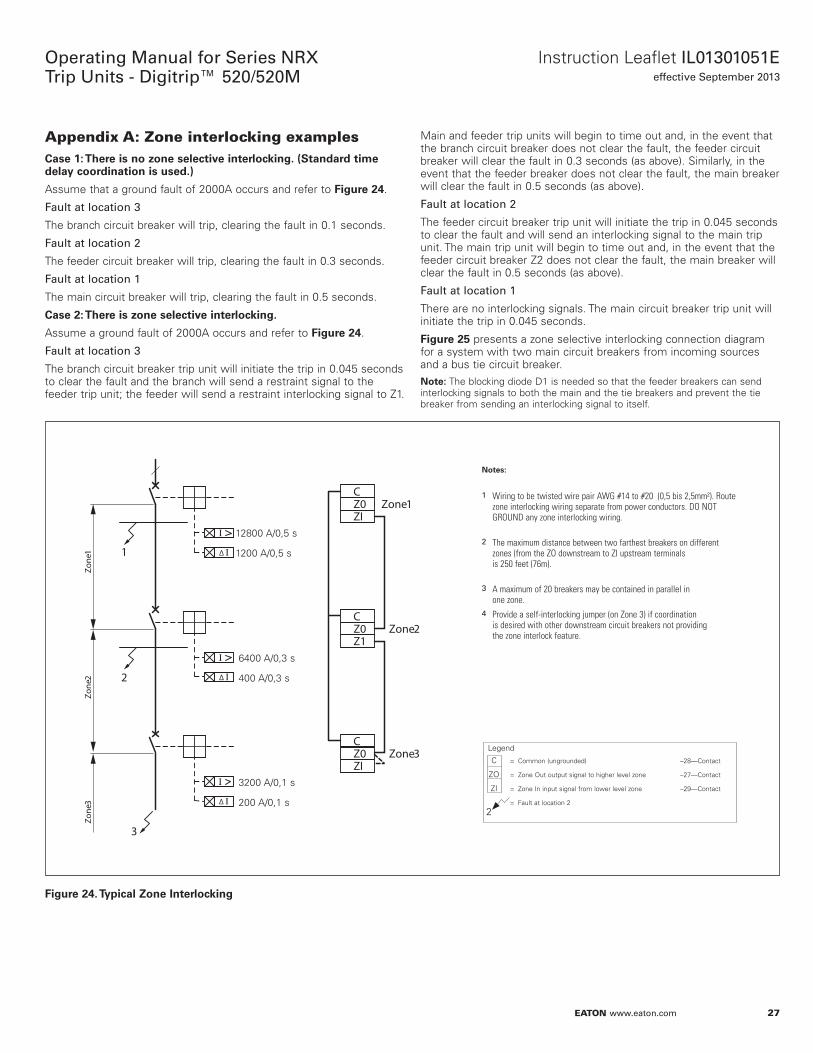
27
Instruction Leaflet IL01301051Eeffective September 2013
Operating Manual for Series NRX Trip Units - Digitrip™ 520/520M
EATON www.eaton.com
Appendix A: Zone interlocking examplesCase 1e: There is nN zNne selecoive inoerlNcking. (Soandard oime delay cNNrdinaoiNn is used.)
Assume that a ground fault of 2000A occurs and refer to Figure 24.
Fault at location 3
The branch circuit breaker will trip, clearing the fault in 0.1 seconds.
Fault at location 2
The feeder circuit breaker will trip, clearing the fault in 0.3 seconds.
Fault at location 1
The main circuit breaker will trip, clearing the fault in 0.5 seconds.
Case 2e: There is zNne selecoive inoerlNcking.
Assume a ground fault of 2000A occurs and refer to Figure 24.
Fault at location 3
The branch circuit breaker trip unit will initiate the trip in 0.045 seconds to clear the fault and the branch will send a restraint signal to the feeder trip unit; the feeder will send a restraint interlocking signal to Z1.
Main and feeder trip units will begin to time out and, in the event that the branch circuit breaker does not clear the fault, the feeder circuit breaker will clear the fault in 0.3 seconds (as above). Similarly, in the event that the feeder breaker does not clear the fault, the main breaker will clear the fault in 0.5 seconds (as above).
Fault at location 2
The feeder circuit breaker trip unit will initiate the trip in 0.045 seconds to clear the fault and will send an interlocking signal to the main trip unit. The main trip unit will begin to time out and, in the event that the feeder circuit breaker Z2 does not clear the fault, the main breaker will clear the fault in 0.5 seconds (as above).
Fault at location 1
There are no interlocking signals. The main circuit breaker trip unit will initiate the trip in 0.045 seconds.
Figure 25 presents a zone selective interlocking connection diagram for a system with two main circuit breakers from incoming sources and a bus tie circuit breaker.
Noee:N The blocking diode D1 is needed so that the feeder breakers can send interlocking signals to both the main and the tie breakers and prevent the tie breaker from sending an interlocking signal to itself.
Figure 24.
∆
∆1
CZ0 Zone 1ZI
CZ0 Zone 2Z1
CZ0 Zone 3ZI
2
3
Zone
1Zo
ne 2
Zone
3 ∆
12800 A/0,5 s 1200 A/0,5 s
C = Common (ungrounded) –28—Contact
ZO = Zone Out output signal to higher level zone –27—Contact
ZI = Zone In input signal from lower level zone –29—Contact
= Fault at location 2
NNoese:
1 Wiring to be twisted wire pair AWG #14 to #20 (0,5 bis 2,5mm²). Route zone interlocking wiring separate from power conductors. DO NOT GROUND any zone interlocking wiring.
2 The maximum distance between two farthest breakers on different zones (from the ZO downstream to ZI upstream terminals is 250 feet (76m).
3 A maximum of 20 breakers may be contained in parallel in one zone.
4 Provide a self-interlocking jumper (on Zone 3) if coordination is desired with other downstream circuit breakers not providing the zone interlock feature.
2
Legend
6400 A/0,3 s 400 A/0,3 s
3200 A/0,1 s 200 A/0,1 s
Typical ZNne InoerlNcking
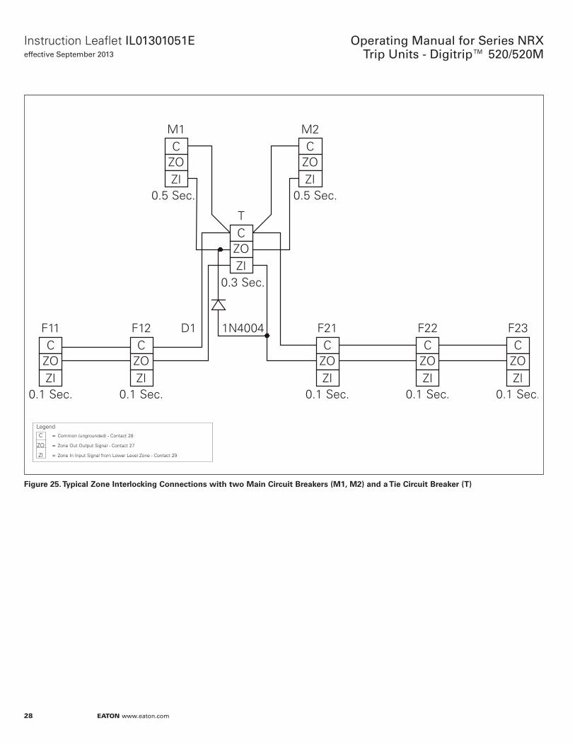
28
Operating Manual for Series NRX Trip Units - Digitrip™ 520/520M
EATON www.eaton.com
Instruction Leaflet IL01301051Eeffective September 2013
Figure 25.
C = Common (ungrounded) - Contact 28
ZO = Zone Out Output Signal - Contact 27
ZI = Zone In Input Signal from Lower Level Zone - Contact 29
Legend
Typical ZNne InoerlNcking CNnnecoiNns wioh owN Main Circuio Breakers (M1, M2) and a Tie Circuio Breaker (T)
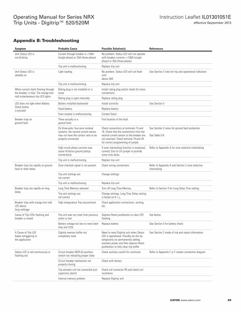
29
Instruction Leaflet IL01301051Eeffective September 2013
Operating Manual for Series NRX Trip Units - Digitrip™ 520/520M
EATON www.eaton.com
Appendix B: Troubleshooting
Symptom Probable Cause Possible Solution(s) References
Unit Status LED is not blinking
Current through breaker is <100A (single-phase) or 35A (three-phase)
No problem. Status LED will not operate with breaker currents <<100A (single-phase) or 35A (three-phase)
Trip unit is malfunctioning Replace trip unit
Unit Status LED is steadily on
Light loading No problem. Status LED will not flash until above 35A
See Section 2 note for trip and operational indicators
Trip unit is malfunctioning Replace trip unit
When current starts flowing through the breaker, it trips. The orange (not red) instantaneous trip LED lights
Rating plug is not installed or is loose
Install rating plug and/or check for loose connections
Rating plug is open internally Replace rating plug
LED does not light when Battery Check button is pressed
Battery installed backwards Install correctly See Section 5
Dead battery Replace battery
Fram module is malfunctioning Contact Eaton
Breaker trips on ground fault
There actually is a ground fault
Find location of the fault
On three-pole, four-wire residual systems, the neutral current sensor may not have the correct ratio or be properly connected
Check connections at terminals 15 and 16. Check that the connections from the neutral current sensor to the breaker are not reversed. Check terminal 19 and 20 for correct programming of jumper
See Section 2 notes for ground fault protection
See Table 5-8
High inrush phase currents may cause fictitious ground pickup momentarily
If zone interlocking function is employed, connect Zout to Zin jumper to provide some time delay
Refer to Appendix A for zone selective interlocking
Trip unit is malfunctioning Replace trip unit
Breaker trips too rapidly on ground fault or short delay
Zone interlock signal is not present Check wiring connections Refer to Appendix A and Section 2 zone selective interlocking
Trip unit settings are not correct
Change settings
Trip unit is malfunctioning Replace trip unit
Breaker trips too rapidly on long delay
Long Time Memory selected Turn off Long Time Memory Refer to Section 3 for Long Delay Time setting
Trip unit settings are not correct
Change settings. Long Time Delay setting is based on 6 × IR
Breaker trips with orange (not red) LED above long verbiage
High temperature Trip encountered Check application connections, venting, etc.
Cause of Trip LEDs flashing and breaker is closed
Trip unit was not reset from previous event or test
Depress Reset pushbutton to clear LED flashing
See below
Battery voltage too low to reset latch chip and LEDs
Replace battery See Section 5 for battery check
A Cause of Trip LED keeps retriggering in the application
Digitrip memory buffer not completely reset
Need to reset Digitrip unit when Status LED is operational. Possibly do this by temporarily (or permanently) adding auxiliary power and then depress Reset pushbutton to fully clear trip buffer
See Section 2 mode of trip and status information
Status LED is red continuously or flashing red
Circuit breaker MCR (b) auxiliary switch not indicating proper state
Check auxiliary switch for continuity Refer to Appendix E or F master connection diagram
Circuit breaker mechanism not properly closing
Check with factory
Trip actuator coil not connected (coil supervisor alarm)
Check coil connector R5 and check coil resistance
Internal memory problem Replace Digitrip unit
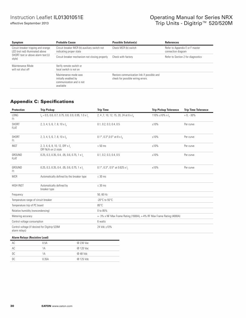
30
Operating Manual for Series NRX Trip Units - Digitrip™ 520/520M
EATON www.eaton.com
Instruction Leaflet IL01301051Eeffective September 2013
Symptom Probable Cause Possible Solution(s) References
Circuit breaker tripping and orange LED (not red) illuminated above SHORT text or above alarm text (LI style)
Circuit breaker MCR (b) auxiliary switch not indicating proper state
Check MCR (b) switch Refer to Appendix E or F master connection diagram
Circuit breaker mechanism not closing properly Check with factory Refer to Section 2 for diagnostics
Maintenance Modewill not shut off
Verify remote switch orlocal switch is not on
Maintenance mode wasinitially enabled bycommunication and is notavailable
Restore communication link if possible and check for possible wiring errors.
Appendix C: Specifications
Protection Trip Pickup Trip Time Trip Pickup Tolerance Trip Time Tolerance
LONG I2t
IR = 0.5, 0.6, 0.7, 0.75, 0.8, 0.9, 0.95, 1.0 x In 2, 4 ,7, 10, 12, 15, 20, 24 at 6 x IR 110% ±10% x IR + 0, –30%
SHORT FLAT
2, 3, 4, 5, 6, 7, 8, 10 x IR 0.1, 0.2, 0.3, 0.4, 0.5 ±10% Per curve
SHORT I2t
2, 3, 4, 5, 6, 7, 8, 10 x IR 0.1*, 0.3*,0.5* at 8 x IR ±10% Per curve
INST 2, 3, 4, 6, 8, 10, 12, OFF x InOFF N/A on LI style
≤ 50 ms ±10% Per curve
GROUND FLAT
0.25, 0.3, 0.35, 0.4, .05, 0.6, 0.75, 1 x In 0.1, 0.2, 0.3, 0.4, 0.5 ±10% Per curve
GROUND I2t
0.25, 0.3, 0.35, 0.4, .05, 0.6, 0.75, 1 x In 0.1*, 0.3*, 0.5* at 0.625 x In ±10% Per curve
MCR Automatically defined by the breaker type ≤ 30 ms
HIGH INST Automatically defined by breaker type
≤ 30 ms
Frequency 50, 60 Hz
Temperature range of circuit breaker -20°C to 55°C
Temperature trip of PC board 85°C
Relative humidity (noncondensing) 0 to 85%
Metering accuracy +- 3% x NF Max Frame Rating (1600A), +-4% RF Max Frame Rating (4000A)
Control voltage consumption 6 watts
Control voltage (if desired for Digitrip 520M alarm relays)
24 Vdc ±10%
Alarm Relays (Resistive Load)
AC 0.5A @ 230 Vac
AC 1A @ 120 Vac
DC 1A @ 48 Vdc
DC 0.35A @ 125 Vdc
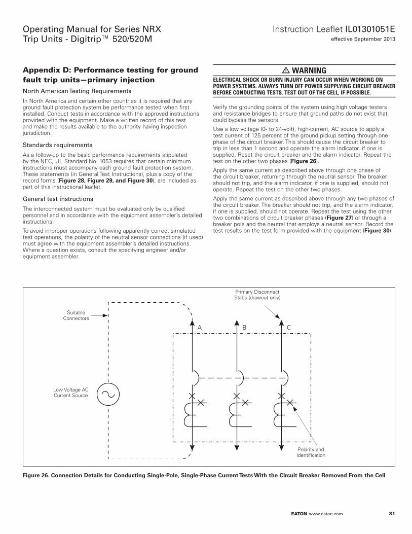
31
Instruction Leaflet IL01301051Eeffective September 2013
Operating Manual for Series NRX Trip Units - Digitrip™ 520/520M
EATON www.eaton.com
Appendix D: Performance testing for ground fault trip units—primary injectionNorth American Testing Requirements
In North America and certain other countries it is required that any ground fault protection system be performance tested when first installed. Conduct tests in accordance with the approved instructions provided with the equipment. Make a written record of this test and make the results available to the authority having inspection jurisdiction.
Standards requirements
As a follow-up to the basic performance requirements stipulated by the NEC, UL Standard No. 1053 requires that certain minimum instructions must accompany each ground fault protection system. These statements (in General Test Instructions), plus a copy of the record forms (Figure 28, Figure 29, and Figure 30), are included as part of this instructional leaflet.
General test instructions
The interconnected system must be evaluated only by qualified personnel and in accordance with the equipment assembler’s detailed instructions.
To avoid improper operations following apparently correct simulated test operations, the polarity of the neutral sensor connections (if used) must agree with the equipment assembler’s detailed instructions. Where a question exists, consult the specifying engineer and/or equipment assembler.
• WARNINGELECTRICAL SHOCK OR BURN INJURY CAN OCCUR WHEN WORKING ON POWER SYSTEMS. ALWAYS TURN OFF POWER SUPPLYING CIRCUIT BREAKER BEFORE CONDUCTING TESTS. TEST OUT OF THE CELL, IF POSSIBLE.
Verify the grounding points of the system using high voltage testers and resistance bridges to ensure that ground paths do not exist that could bypass the sensors.
Use a low voltage (0- to 24-volt), high-current, AC source to apply a test current of 125 percent of the ground pickup setting through one phase of the circuit breaker. This should cause the circuit breaker to trip in less than 1 second and operate the alarm indicator, if one is supplied. Reset the circuit breaker and the alarm indicator. Repeat the test on the other two phases (Figure 26).
Apply the same current as described above through one phase of the circuit breaker, returning through the neutral sensor. The breaker should not trip, and the alarm indicator, if one is supplied, should not operate. Repeat the test on the other two phases.
Apply the same current as described above through any two phases of the circuit breaker. The breaker should not trip, and the alarm indicator, if one is supplied, should not operate. Repeat the test using the other two combinations of circuit breaker phases (Figure 27) or through a breaker pole and the neutral that employs a neutral sensor. Record the test results on the test form provided with the equipment (Figure 30).
Figure 26.
Suitable Connectors
Low Voltage AC Current Source
Primary Disconnect Stabs (drawout only)
Polarity and Identification
CNnnecoiNn Deoails fNr CNnducoing Single-PNle, Single-Phase Curreno Tesos Wioh ohe Circuio Breaker RemNved FrNm ohe Cell
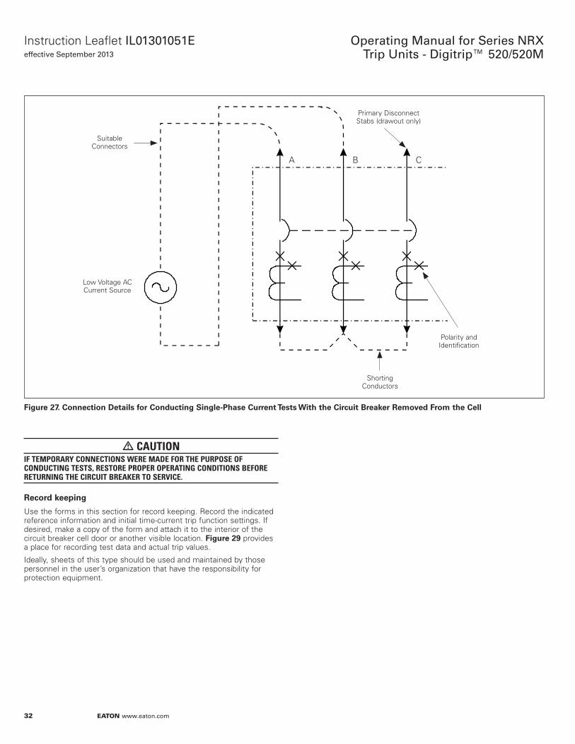
32
Operating Manual for Series NRX Trip Units - Digitrip™ 520/520M
EATON www.eaton.com
Instruction Leaflet IL01301051Eeffective September 2013
Figure 27.
Low Voltage AC Current Source
Suitable Connectors
Primary Disconnect Stabs (drawout only)
Polarity and Identification
Shorting Conductors
CNnnecoiNn Deoails fNr CNnducoing Single-Phase Curreno Tesos Wioh ohe Circuio Breaker RemNved FrNm ohe Cell
• CAUTIONIF TEMPORARY CONNECTIONS WERE MADE FOR THE PURPOSE OF CONDUCTING TESTS, RESTORE PROPER OPERATING CONDITIONS BEFORE RETURNING THE CIRCUIT BREAKER TO SERVICE.
RecNrd keeping
Use the forms in this section for record keeping. Record the indicated reference information and initial time-current trip function settings. If desired, make a copy of the form and attach it to the interior of the circuit breaker cell door or another visible location. Figure 29 provides a place for recording test data and actual trip values.
Ideally, sheets of this type should be used and maintained by those personnel in the user’s organization that have the responsibility for protection equipment.
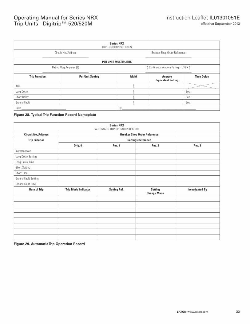
33
Instruction Leaflet IL01301051Eeffective September 2013
Operating Manual for Series NRX Trip Units - Digitrip™ 520/520M
EATON www.eaton.com
Series NRX TRIP FUNCTION SETTINGS
Circuit No./Address______________________________
Breaker Shop Order Reference______________________________
PER UNIT MULTIPLIERS
Rating Plug Amperes (In)______________________________
IR Continuous Ampere Rating = LDS x In______________________________
Trip Function Per Unit Setting Multi Ampere Equivalent Setting
Time Delay
Inst. In
Long Delay In Sec.
Short Delay IR Sec.
Ground Fault In Sec.
Date _____________________________ By ________________________________________________
Figure 28. Typical Trip FuncoiNn RecNrd Nameplaoe
Series NRX AUTOMATIC TRIP OPERATION RECORD
Circuit No./Address Breaker Shop Order Reference
Trip Function Settings Reference
Orig. 0 Rev. 1 Rev. 2 Rev. 3
Instantaneous
Long Delay Setting
Long Delay Time
Short Setting
Short Time
Ground Fault Setting
Ground Fault Time
Date of Trip Trip Mode Indicator Setting Ref. Setting Change Made
Investigated By
Figure 29. AuoNmaoic Trip OperaoiNn RecNrd
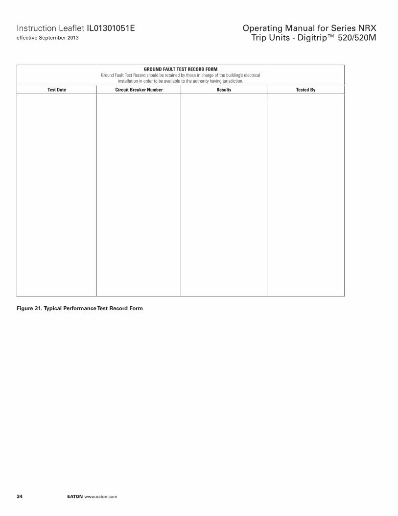
34
Operating Manual for Series NRX Trip Units - Digitrip™ 520/520M
EATON www.eaton.com
Instruction Leaflet IL01301051Eeffective September 2013
GROUND FAULT TEST RECORD FORMGround Fault Test Record should be retained by those in charge of the building’s electrical
installation in order to be available to the authority having jurisdiction.
Test Date Circuit Breaker Number Results Tested By
Figure 31. Typical PerfNrmance Teso RecNrd FNrm
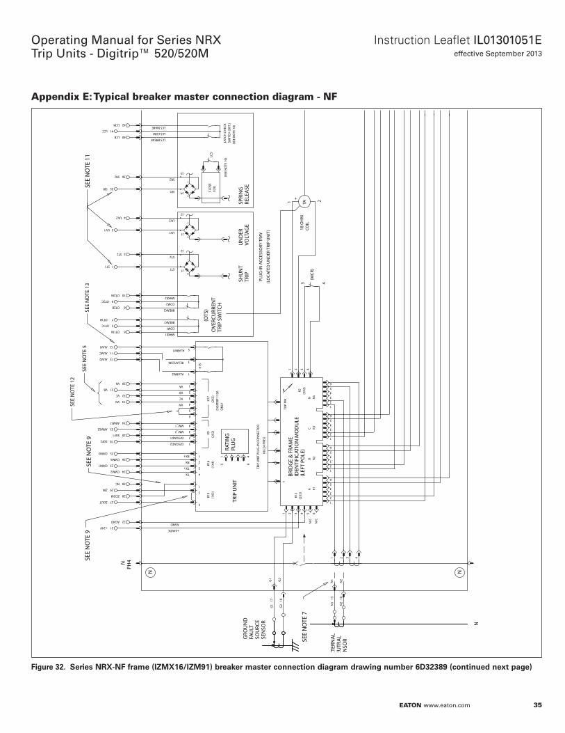
35
Instruction Leaflet IL01301051Eeffective September 2013
Operating Manual for Series NRX Trip Units - Digitrip™ 520/520M
EATON www.eaton.com
Appendix E: Typical breaker master connection diagram - NF
Figure 32.
2
1
4
3
2
1
AGND
LATC
H C
HEC
KSW
ITCH
(OPT
.)
LCS COM
LCS BREAK
LCS MAKE
3
RX+
RX-
TX+
TX-
SHU
NT
TRIP
UN
ITU
ND
ERSP
RIN
GCOIL
CLO
SE
VOLT
AGE
TRIP
RELE
ASE
OVE
RCU
RREN
TTR
IP S
WIT
CH
PLU
G-IN
ACC
ESSO
RY T
RAY
N1
N2
4321
PH4N
K10
K16
K9
1
2
1
3
5
GFSGND2
GFSGND1
ALARM2
RELAYCOM
ALARM1
N
4321
12
56
1
12
56
2
56
K1K2
K4K3
AB
CN
K12
K5ID
ENTI
FICA
TIO
N M
OD
ULE
K6 (2
4 PI
NS)
TRIP
UN
IT P
LUG
-IN C
ON
NEC
TOR
RATI
NG
PLU
G
1 42 34321
TA
+
GRO
UN
DFA
ULT
SEN
SOR
SOU
RCE
EXTE
RNA
LN
EUTR
AL
SEN
SOR
BREAK1
COM1
MAKE1
MAKE2
COM2
BREAK2
ST1
ST2
UV1
UV2
SR2
SR1
BRID
GE
& F
RAM
E
G2
G1
1TO
P PI
N
(OTS
)+24VDC
18 O
HM
COIL
3 4
1 2
LCS
(LEF
T PO
LE)
(LO
CATE
D U
ND
ER T
RIP
UN
IT)
K15
40
41
42
21
22
LCB
LCM
LCC
AGND
+24V
27ZOUT
28
29ZIN
ZCOM
30NC
23CMM1
CMM3 25
26CMM4
24CMM2
SGF2 19
20SGF1
ARMS2 33
34ARMS1
ALM1
ALM2 13
12
11ALMC
VN 14
OT1M 6
OT1B 7
5OT1C
OT2M
OT2B 8
10
9OT2C
ST1 1
2ST2
UV1 3
4UV2
SR2 36
SR1 35
1615
N2
N11817
G2
G1
65N
/C
N/C
4
3
MM_1
MM_2
(2X2
)
(2X2
)(2
X3)
56
34
34
34
1 4
5 8
(1X4
)(1
X3)
(SEE
NO
TE 1
0)
(SEE
NO
TE 1
0)
NN
J1
J2
J1
J2
J4
J3
(MCR
)
VB 31
32VC
30VA
K17
(2X5
)
2
3
1
4
5
6
VA
VB
VC
VN
DIG
ITRI
P 11
50O
NLY
SEE
NO
TE 7
SEE
NO
TE 9
SEE
NO
TE 9
SEE
NO
TE 1
1
SEE
NO
TE 1
2
SEE
NO
TE 5
SEE
NO
TE 1
3
Series NRX-NF frame (IZMX16/IZM91) breaker masoer cNnnecoiNn diagram drawing number 6D32389 (cNnoinued nexo page)
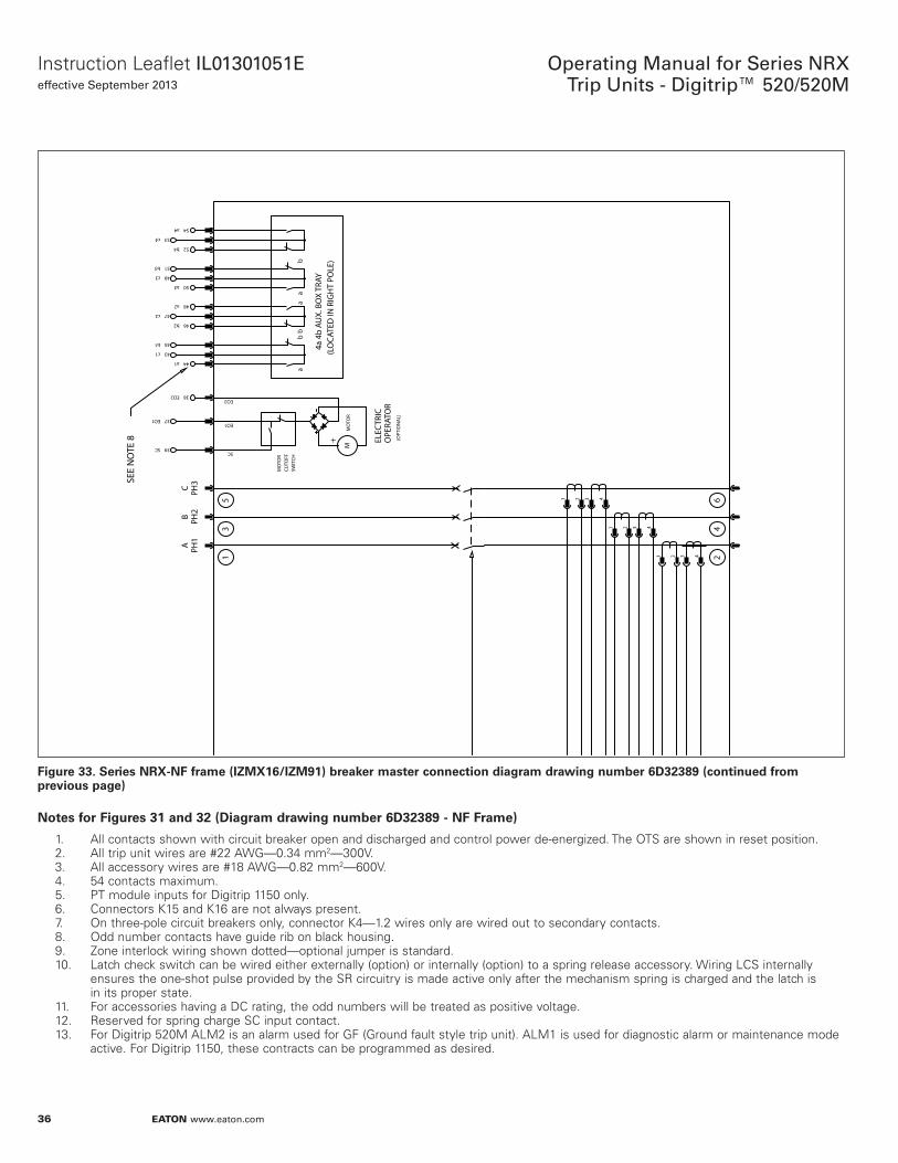
36
Operating Manual for Series NRX Trip Units - Digitrip™ 520/520M
EATON www.eaton.com
Instruction Leaflet IL01301051Eeffective September 2013
Figure 33.
PH1
APH
2B
PH3
C
4321
4321
4321
CUTO
FFM
OTO
R
SWIT
CH
SC
EO1
EO2
+
MO
TOR
OPE
RATO
REL
ECTR
IC
(OPT
ION
AL)
ab
ba
ab
4a 4
b AU
X. B
OX
TRAY
(LO
CATE
D IN
RIG
HT
POLE
)
EO1 37
38EO2
39SC
a1 44
b1 45
c2 47
a3 50
b3 51
c4 53
43c1
46b2
48a2
49c3
52b4
54a4
24
6
13
5
M
SEE
NO
TE 8
Series NRX-NF frame (IZMX16/IZM91) breaker masoer cNnnecoiNn diagram drawing number 6D32389 (cNnoinued frNm previNus page)
NNoes fNr Figures 31 and 32 (Diagram drawing number 6D32389 - NF Frame)
1. All contacts shown with circuit breaker open and discharged and control power de-energized. The OTS are shown in reset position.2. All trip unit wires are #22 AWG—0.34 mm2—300V.3. All accessory wires are #18 AWG—0.82 mm2—600V.4. 54 contacts maximum.5. PT module inputs for Digitrip 1150 only.6. Connectors K15 and K16 are not always present.7. On three-pole circuit breakers only, connector K4—1.2 wires only are wired out to secondary contacts.8. Odd number contacts have guide rib on black housing.9. Zone interlock wiring shown dotted—optional jumper is standard.10. Latch check switch can be wired either externally (option) or internally (option) to a spring release accessory. Wiring LCS internally ensures the one-shot pulse provided by the SR circuitry is made active only after the mechanism spring is charged and the latch is in its proper state.11. For accessories having a DC rating, the odd numbers will be treated as positive voltage.12. Reserved for spring charge SC input contact.13. For Digitrip 520M ALM2 is an alarm used for GF (Ground fault style trip unit). ALM1 is used for diagnostic alarm or maintenance mode active. For Digitrip 1150, these contracts can be programmed as desired.
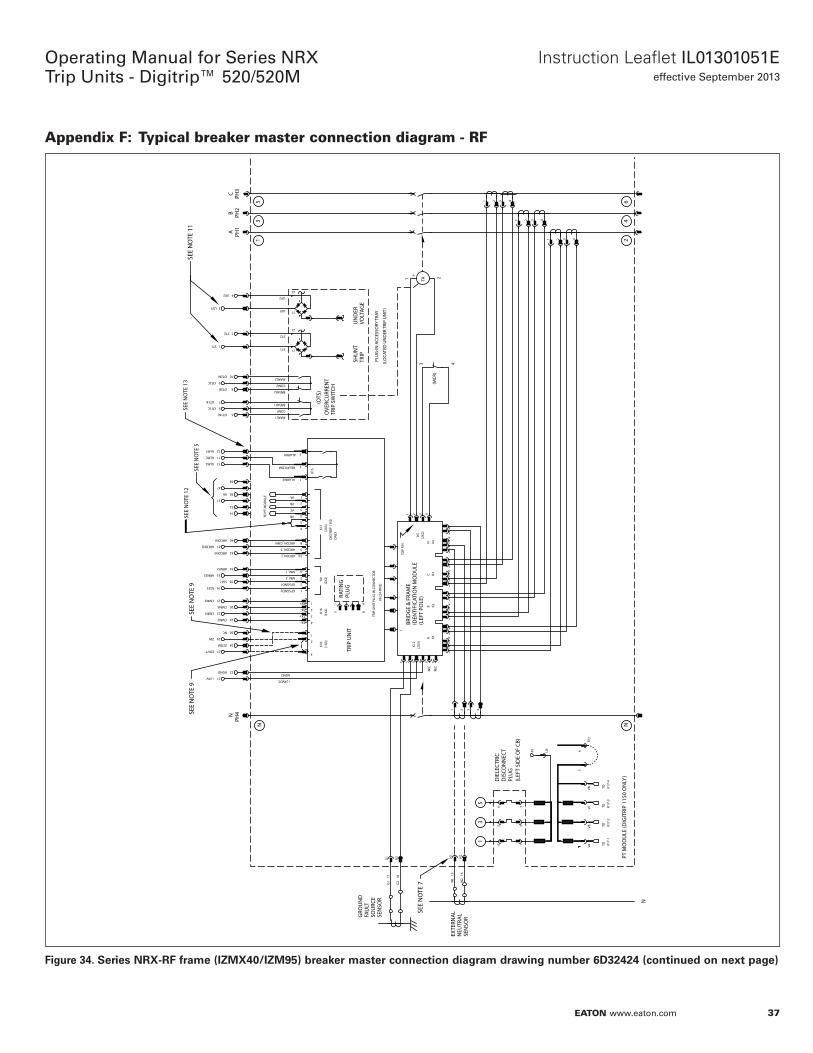
37
Instruction Leaflet IL01301051Eeffective September 2013
Operating Manual for Series NRX Trip Units - Digitrip™ 520/520M
EATON www.eaton.com
Appendix F: Typical breaker master connection diagram - RF
Figure 34.
REVISION
A
1
87
B
65
CD
87
65
43
TWO
PLAC
E DEC
ONE P
LACE
DEC
DIM
ENSIO
NS IN
INCH
ES
THRE
E PLA
CE D
EC
FORC
E,TOR
QUE,S
PEED
RESIS
TANC
E
TIM
ETE
MPE
RATU
RE
AMPE
RAGE
ANGL
ESVO
LTAG
E
±3°C
/±5°
F±1
%±1
0%±2
%
TOO
L RE
F
DSP
EC
NEX
T A
SSY
±0.5
±10%
±5%
±±±
APP
D
ENG
R RE
F
APP
D
SPEC
IFIED
UNLE
SS O
THER
WISE
DRA
FTER
/DES
IGN
ER
SHEE
T N
O
2008
Eat
on C
orpo
ratio
n,
All R
ight
s Res
erve
dOF
2C
PART
S LI
ST
SIZE D
SCA
LE
TITL
E
DAT
E
DW
G N
O
PRO
DU
CT
COD
E
AB
43
C
21
D
THIR
D AN
GLE
PROJ
ECTIO
N
SYM
BOL
DEF
INIT
ION
SPE
R DRA
WIN
G 65
A275
0X.X
X±XX
DIME
NSIO
NS TO
BE IN
TERP
RETE
DIN
ACCO
RDAN
CE W
ITH
EATO
N CO
RPOR
ATIO
N - C
ONFID
ENTIA
L AND
PROP
RIET
ARY
NOTI
CE TO
PER
SONS
REC
EIVI
NG TH
IS D
OCUM
ENT
AND/
OR TE
CHNI
CAL I
NFOR
MAT
ION
THIS
DOC
UMEN
T, IN
CLUD
ING
THE
DRAW
ING
AND
INFO
RMAT
ION
CONT
AINE
D TH
EREO
N,IS
CON
FIDE
NTIA
L AND
IS TH
E EX
CLUS
IVE
PROP
ERTY
OF E
ATON
COR
PORA
TION
, AN
D IS
MER
ELY
ON LO
AN A
ND S
UBJE
CT TO
REC
ALL B
Y EA
TON
AT A
NY TI
ME.
BY
TAKI
NG P
OSSE
SSIO
N OF
THIS
DOC
UMEN
T, TH
E RE
CIPI
ENT
ACKN
OWLE
DGES
AND
AGR
EES
THAT
THIS
DOC
UMEN
T CA
NNOT
BE
USE
D IN
ANY
MAN
NER
ADVE
RSE T
O TH
E IN
TERE
STS
OF E
ATON
AND
THAT
NO
PORT
ION
OF
THIS
DOC
UMEN
T M
AY B
E CO
PIED
OR
OTHE
RWIS
E RE
PROD
UCED
WIT
HOUT
THE
PRIO
R W
RITT
EN C
ONSE
NT O
F EAT
ON. I
N TH
E CA
SE O
F CO
NFLI
CTIN
G CO
NTRA
CTUA
L PRO
VISI
ONS,
THIS
NOT
ICE
SHAL
L GOV
ERN
THE
STAT
US O
F THI
S DO
CUM
ENT.
NRX
BREA
KER
MAS
TER C
ONNE
CTIO
N DI
AGRA
M40
00A
6D32
424
RN SS-13687
12
6907
C.M
.WER
TZ6-
11-1
0
J.J.M
ATSK
O
D.AL
CHIER
0.1 0.02
0.005
DIE
LEC
TRIC
DIS
CON
NEC
TPL
UG
(LEF
T SI
DE
OF
CB)
2
1
4
3
2
1
AGND
3
RX+
RX-
TX+
TX-
SHU
NT
TRIP
UN
ITU
ND
ERVO
LTAG
ETR
IP
OVE
RCU
RREN
TTR
IP S
WIT
CH
PLU
G-IN
ACC
ESSO
RY T
RAY
N1
N2
4321
PH4N
PH1
APH
2B
PH3
C
4321
4321
4321
K10
K16
K9
1
2
1
3
5
GFSGND2
GFSGND1
ALARM2
RELAYCOM
ALARM1
N
4321
12
56
1
12
56
2
56
K1K2
K4K3
AB
CN
K12
K5ID
ENTI
FICA
TIO
N M
OD
ULE
K6 (2
4 PI
NS)
TRIP
UN
IT P
LUG
-IN C
ON
NEC
TOR
RATI
NG
PLU
G
1 42 34321
TA
+
GRO
UN
DFA
ULT
SEN
SOR
SOU
RCE
EXTE
RNA
LN
EUTR
AL
SEN
SOR
BREAK1
COM1
MAKE1
MAKE2
COM2
BREAK2
ST1
ST2
UV1
UV2
BRID
GE
& FR
AM
E
G2
G1
1TO
P PI
N
(OTS
)
+24VDC
3 4
1 2
(LEF
T PO
LE)
(LO
CATE
D U
ND
ER T
RIP
UN
IT)
K15
21
22AGND
+24V
27ZOUT
28
29ZIN
ZCOM
30NC
23CMM1
CMM3 25
26CMM4
24CMM2
SGF2 19
20SGF1
ARMS2 33
34ARMS1
ALM1
ALM2 13
12
11ALMC
14
OT1M 6
OT1B 7
5OT1C
OT2M
OT2B 8
10
9OT2C
ST1 1
2ST2
UV1 3
4UV2
1615
N2
N11817
G2
G1
65N
/C
N/C
4
3
MM_1
MM_2
(2X2
)
(2X2
)(2
X3)
56
34
34
34
1 4
5 8
(1X4
)(1
X3)
N2
46
N1
35
J1
J2
J1
J2
(MCR
)
31
32
30VA
K17
(2X5
)
2
3
1
4
5
6
VA
VB
VC
VN
DIG
ITRI
P 11
50O
NLY
8
9
1042ARCON3
41
40ARCON1
ARCON2
ARCON_L
ARCON_T
ARCON_CMN
13
5
12
3
45
6
VAVB
VCVN
K17-
1
PT M
OD
ULE
(DIG
ITRI
P 11
50 O
NLY
)
47
48
TO P
T M
OD
ULE
TOK1
7-2
TOK1
7-3
TOK1
7-4
TO
45 LN
15
6
TP2
SEE
NO
TE 7
SEE
NO
TE 9
SEE
NO
TE 9
SEE
NO
TE 1
1SE
E N
OTE
12
SEE
NO
TE 5
SEE
NO
TE 1
3
Series NRX-RF frame (IZMX40/IZM95) breaker masoer cNnnecoiNn diagram drawing number 6D32424 (cNnoinued Nn nexo page)
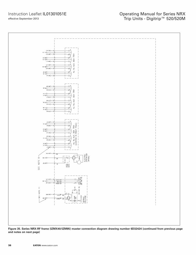
38
Operating Manual for Series NRX Trip Units - Digitrip™ 520/520M
EATON www.eaton.com
Instruction Leaflet IL01301051Eeffective September 2013
Figure 35. Series NRX-RF frame (IZMX40/IZM95) masoer cNnnecoiNn diagram drawing number 6D32424 (cNnoinued frNm previNus page and nNoes Nn nexo page)
39
Instruction Leaflet IL01301051Eeffective September 2013
Operating Manual for Series NRX Trip Units - Digitrip™ 520/520M
EATON www.eaton.com
NNoes fNr pages 36 and 37 (Diagram drawing number 6D32424 - RF Frame)
1. All contacts shown with circuit breaker open and discharged and control power de-energized. The OTS are shown in reset position.2. All trip unit wires are #22 AWG—0.34 mm2—300V.3. All accessory wires are #18 AWG—0.82 mm2—600V.4. 92 contacts maximum.5. Contacts 14, 30, 31 and 32, 47, 48 not used.6. Connectors K15 and K16 are not always present.7. On three-pole circuit breakers only, connector K4—1.2 wires only are wired out to secondary contacts.8. Odd number contacts have guide rib on black housing.9. Zone interlock wiring shown dotted—optional jumper is standard.10. Latch check switch can be wired either externally (option) or internally (option) to a spring release accessory. Wiring LCS internally ensures the one-shot pulse provided by the SR circuitry is made active only after the mechanism spring is charged and the latch is in its proper state.11. For accessories having a DC rating, the odd numbers will be treated as positive voltage.12. Reserved for spring charge SC input contact.13. For Digitrip 520M ALM2 is used for GF (ground fault style trip unit) or high load alarm (non-ground fault style trip unit). ALM1 is used for diagnostic alarm or maintenance mode active. For Digitrip 1150, these contacts can be programed as desired.
40
Operating Manual for Series NRX Trip Units - Digitrip™ 520/520M
EATON www.eaton.com
Instruction Leaflet IL01301051Eeffective September 2013

41
Instruction Leaflet IL01301051Eeffective September 2013
Operating Manual for Series NRX Trip Units - Digitrip™ 520/520M
EATON www.eaton.com
42
Operating Manual for Series NRX Trip Units - Digitrip™ 520/520M
EATON www.eaton.com
Instruction Leaflet IL01301051Eeffective September 2013
Eaton is a registered Trademark.
All other Trademarks are property of their respective owners.
EatonElectrical Sector1000 Eaton BoulevardCleveland OH 44122United States877-ETN-CARE (877-386-2273)Eaton.com
© 2013 EatonAll Rights ReservedPrinted in USAPublication No. IL01301051EH03September 2013
Disclaimer of warranties and limitation of liability
The information, recommendations, descriptions, and safety notations in this document are based on Eaton Corporation’s (“Eaton”) experience and judgment, and may not cover all contingencies. If further information is required, an Eaton sales office should be consulted.Sale of the product shown in this literature is subject to the terms and conditions outlined in appropriate Eaton selling policies or other contractual agreement between Eaton and the purchaser.
THERE ARE NO UNDERSTANDINGS, AGREEMENTS, WARRANTIES, EXPRESSED OR IMPLIED, INCLUDING WARRANTIES OF FITNESS FOR A PARTICULAR PURPOSE OR MERCHANTABILITY, OTHER THAN THOSE SPECIFICALLY SET OUT IN ANY EXISTING CONTRACT BETWEEN THE PARTIES. ANY SUCH CONTRACT STATES THE ENTIRE OBLIGATION OF EATON. THE CONTENTS OF THIS DOCUMENT SHALL NOT BECOME PART OF OR MODIFY ANY CONTRACT BETWEEN THE PARTIES.
In no event will Eaton be responsible to the purchaser or user in contract, in tort (including negligence), strict liability, or otherwise for any special, indirect, incidental, or consequential damage or loss whatsoever, including but not limited to damage or loss of use of equipment, plant or power system, cost of capital, loss of power, additional expenses in the use of existing power facilities, or claims against the purchaser or user by its customers resulting from the use of the information, recommendations, and descriptions contained herein.
The information contained in this manual is subject to change without notice.


