SERIES NG 500 dRaINaGE aNd SERvIcE ductS · NG 514 Fin Drains 6 NG 515 Narrow Filter Drains 8 ......
18
SERIES NG 500 dRaINaGE aNd SERvIcE ductS contents Clause Title Page NG 501 Pipes for Drainage and Service Ducts 2 NG 502 Excavation for Pipes and Chambers 3 NG 503 Bedding, Laying and Surrounding of Pipes 3 NG 504 Jointing of Pipes 3 NG 505 Backfilling of Trenches and Filter Drains 4 NG 507 Chambers 4 NG 508 Gullies and Pipe Junctions 5 NG 509 Testing and Cleaning 5 NG 510 Surface Water Channels and Drainage Channel Blocks 5 NG 511 Land Drains 6 NG 512 Backfilling to Pipe Bays and Verges on Bridges 6 NG 513 Permeable Backing to Earth Retaining Structures 6 NG 514 Fin Drains 6 NG 515 Narrow Filter Drains 8 NG 516 Combined Drainage and Kerb Systems 8 NG 517 Linear Drainage Channel Systems 8 NG 518 (05/01) Thermoplastics Structured Wall Pipes and Fittings 9 NG 521 (11/03) Low Pressure High Volume Jetting of Drainage Systems 10 NG Sample Appendices A1 MaNuaL OF cONtRact dOcuMENtS FOR HIGHWaY WORKS vOLuME 2 NOtES FOR GuIdaNcE ON tHE SPEcIFIcatION FOR HIGHWaY WORKS Amendment - November 2009 1
-
Upload
nguyenphuc -
Category
Documents
-
view
219 -
download
1
Transcript of SERIES NG 500 dRaINaGE aNd SERvIcE ductS · NG 514 Fin Drains 6 NG 515 Narrow Filter Drains 8 ......

SERIES NG 500 dRaINaGE aNd SERvIcE ductS
contentsClause Title Page
NG501 PipesforDrainage andServiceDucts 2
NG502 ExcavationforPipesand Chambers 3
NG503 Bedding,Layingand SurroundingofPipes 3
NG504 JointingofPipes 3
NG505 BackfillingofTrenches andFilterDrains 4
NG507 Chambers 4
NG508 GulliesandPipeJunctions 5
NG509 TestingandCleaning 5
NG510 SurfaceWaterChannelsand DrainageChannelBlocks 5
NG511 LandDrains 6
NG512 BackfillingtoPipeBaysand VergesonBridges 6
NG513 PermeableBackingto EarthRetainingStructures 6
NG514 FinDrains 6
NG515 NarrowFilterDrains 8
NG516 CombinedDrainageand KerbSystems 8
NG517 LinearDrainageChannel Systems 8
NG518 (05/01)Thermoplastics StructuredWallPipesand Fittings 9
NG521 (11/03)LowPressureHigh VolumeJettingofDrainage Systems 10
NG SampleAppendices A1
MaNuaL OF cONtRact dOcuMENtS FOR HIGHWaY WORKS vOLuME 2 NOtES FOR GuIdaNcE ON tHE SPEcIFIcatION FOR HIGHWaY WORKS
Amendment-November2009 1
Volume2 SeriesNG500NotesforGuidanceontheSpecificationforHighwayWorks DrainageandServiceDucts
dRaINaGE aNd SERvIcE ductS
NG 501 Pipes for drainage and Service ducts
1 Pipescanbemadeofmaterialsthatdeflectrelativelylittleunderloadbeforecracking(rigidpipes)orofmaterialsthatwilltoleratelargedeflectionsunderloadbeforeinwardbucklingoccurs(flexiblepipes).Flexiblejointsenableeithertypeofpipetotakeupdifferentialsettlementwithintheground.
2 (05/04)TheSpecificationincludesawiderangeofpipematerials.TheContractorshouldnormallybeofferedinAppendix5/1thefullselectionofalternativepipeandbeddingcombinationsdeterminedinaccordancewithAdviceNoteHA40(DMRB4.2.5)asdetailedintheHCDforpipesupto900mminternaldiameter.TherequiredpipestiffnessandimpactresistanceforplasticspipesshouldbespecifiedinAppendix5/1.TherequirementsforthermoplasticspipesandfittingswillnormallybeasinClause518withrawmaterialandqualitycontrolrequirementsasinNG518.
Pipedculvertsupto900mminternaldiametershouldbespecifiedinSeries500.Drains,boxculverts,pipedculverts(andotherdrains)ofclearspanorinternaldiameterexceeding900mmaresubjecttoOverseeingOrganisation’stechnicalapprovalandshouldcomplywithSeries2500.Aboxculvertshouldnotbespecifiedwhereeithera(concrete)boxculvertora(corrugatedsteel)pipedculvertwouldbetechnicallyacceptable.Whereverpossible,theContractorshouldbeofferedachoiceandtheOverseeingOrganisationshouldbeconsultedduringtheschemepreparation.Boxculverts,pipedculverts(andotherdrains)ofclearspanorinternaldiameterexceeding900mmarestructuressubjecttotheOverseeingOrganisation’stechnicalapproval.CareshouldbetakentoensurethattherearenoinconsistenciesbetweenanyspecificrequirementsincludedinanoutlineApprovalinPrincipleformandthegeneralrequirementsofSeries500.Wherenecessary,Contract-specificamendmentsshouldbeincludedinAppendix0/1or0/2toachieveconsistency.
MostofthepipesincludedintheSpecificationwillnormallybesatisfactoryfromthehydraulicflowcapacityfactor.Howeversomeproducts,especiallycorrugatedpipes,canvaryfromthenorm(egclay/concrete)andbetweenmanufacturers.Theeffectofarougherpipeshouldbeconsideredonthesystemasawholeandnotjustonthelengthinquestion.Apipewhichisnotacceptableonastraightexchangebasismaybeacceptableifdiametersonadjacentlengthsareadjusted.Appendix5/1shouldprovidethebasison
whichtheContractoristosubmithisproposalsforpipetypesandmakes.
3 (11/03)Anytendencytoattackbyacidicgroundwaterorsulfatespresentinthebackfillorthegroundshouldbetakenintoaccountwhentheuseofconcrete,asbestoscement,steelorironpipesisbeingconsideredforinclusioninthescheduleofacceptablealternativesinAppendix5/1.TheadvicedescribedinClauseNG1704shouldbeconsideredregardingtheriskofthaumasitesulfateattackonconcreteusedindrainage.Whenacidsoils(pHlessthan6.5)areencountered,expertadviceshouldbesought.Thereissomeevidencethatpipesmadeofsulfate-resistingcementandasbestoscementpipeswilltolerateapHaslowas6.0.ThelimitingvaluemaybereducedtopH5.5whenabitumencoatingisappliedtothepipe.SulfateattackonconcreteisdealtwithinBuildingResearchEstablishmentSpecialDigest1.Asbestoscementpipeswilltoleratethesameorderofsulfatesasconcretemadefromsulfate-resistingcement.Moredetailedinformationmaybeobtainedfromthemanufacturers.Protectiontothelowerthirdoftheinsideofcorrugatedsteelpipedculvertsbymeansofanasphaltorinsituconcretecoatingwillberequiredwherestonesandrocksarelikelytobecarriedbytheflow.Ironpipesaretreatedwithapitchorbitumencoatingandhavehighdurabilityinmostsoils,butwhenacidconditionsareknowntobepresenttheadditionalprotectionofapolyethylenesleeveisdesirable.Clay,GRP,pitchfibreandPVC-Upipesareresistanttoawiderangeofgroundwaterchemicals.
4 Forcorrugatedsteelpipesoflockseamfabricationwithadiameternotexceeding900mm,thespecificationofmetalthicknessshouldbegiveninAppendix5/1.Thetablesissuedbymanufacturersrecommendthicknessescorrespondingtothediameteranddepthoffillabovethepipe.
5 Pipesofmorethanonetypewithinanyindividualdrainorserviceductbetweenconsecutivechamberswillbeexceptional.Whateverthecircumstancegivingrisetotheproposal,considerationshouldbegiventowhetherthejointbetweenthetwopipeswillprovideanappropriatelywatertightjointandasmoothinnertransitionforroddingpurposes.
6 Plasticspipesmaydeteriorateafteralongperiodinsunlight.WherepipeshavebeenmanufacturedandstoredbeforebeingdeliveredtotheSite,itmaybenecessaryfortheContractortocoverthemuntiltheyareinstalled.
Amendment-May2004 2

Volume 2Notes for Guidance on the Specifications for Highway Works
Series NG 500Drainage and Service Ducts
3
7 (05/01) Any individual cable duct under a road mayhave to accept a power or a communication cablealthough these are normally placed in separate ducts.Certain pipe materials have been excluded from theSpecification for use as ducts because cables cannot bereadily drawn through them. Clauses NG 518, NG 1421and NG 1530 give further information on the use ofducts for electrical work. Ducts should be scheduled ina similar way to pipes in Appendix 5/2. Any specialrequirements of Statutory Undertakers etc. should bestated clearly.
8 (11/03) Trenchless and minimum dig installation isthe means of installing, replacing and renovating pipes,ducts and small tunnels with minimal or no excavationfrom the surface. MCHW 5, Series 8000 covers therequirements for trenchless and minimum diginstallation of highway drainage, service ducts, sleevesand culverts up to and including 900 mm nominalinternal diameter or width. The information requiredfrom the designer/compiler that will detail theperformance required from the trenchless installationshould be given in NG Sample Appendix 80/1(MCHW 5.8.3).
NG 502 Excavation for Pipes and Chambers
1 In the preparation of Appendix 6/3, it may beconsidered appropriate to permit battering of slopeswhere this would not affect adversely the PermanentWorks or the basis of structural design of the pipe/trench.
2 (11/03) In the event of excavation to a greater depththan necessary the Contractor is obliged to reinstate.The use of ST1 concrete to remedy excess excavationshould be restricted to areas where compaction isimpracticable. Where the floor of the trench passesthrough a localised area of disturbed and uncompactedsoil or softened clay further excavation and replacementwith appropriate material may be required to allow pipelaying to proceed.
3 Where pipes are to be installed beneath heavilytrafficked existing roads, etc, where it is undesirablethat the existing ground surface should be disturbed,consideration should always be given to the possibilityof inserting the pipe by suitable thrustboring or jackingprocesses.
NG 503 Bedding, Laying and Surrounding ofPipes
1 (05/04) Pipe bedding material should be readilyobtainable since a wide range of gradings and sizescomplying with BS EN 13242 are permitted. Pipebedding material needs to flow readily and compact
uniformly, thus a low coefficient of uniformity isnecessary. In order to make savings in coarser granularmaterials a sand bed may be adopted. Surround to pipesshould be in bedding material or acceptable material(Class 8) as appropriate to the alternatives shown in theHCD. Coarse granular material may consist of naturalaggregate, recycled coarse aggregate, recycled concreteaggregate, artificial or blended combinations of theseaggregates, which satisfy the requirements of thespecification.
2 (11/05) The limiting values in sub-Clauses 503.4 and503.5 have been chosen to ensure that problems do notoccur due to oxidation of reduced sulfur compoundssuch as pyrite. Further guidance is given insub-Clause NG 601.8 and Clause NG 644.
3 (05/04) A distinction is to be made between therequirements of bedding, haunching and surroundingand those of backfilling. The former comprise alloperations of trench fill up to a level 300 mm above thetop of the barrel of the pipe. Backfilling constitutes theremaining operations up to ground level in verges andopen ground and up to formation or sub-formation levelunder carriageways. Work above formation levelconstitutes construction or reinstatement of thepavement (see NG 706).
4 (05/04) Concrete surround should be usedexceptionally, eg for protection of pipes againstmechanical damage from subsequent operations afterconstruction of the pipeline and where remedialmeasures due to over excavation are required.Protection of existing pipes where necessary may takethe form of a concrete arch or slab above the pipe.
NG 504 Jointing of Pipes
1 Pipe joints for surface water drains, unlike fouldrains, do not always have to be completely watertight.Small amounts of seepage as allowed insub-Clause 509.7 can be tolerated particularly wherepipes are laid in cuttings or below the water table.However, joints in pipes in soils that are predominantlyfine sands or coarse silts should have watertight jointsto prevent soil particles passing through the joint intothe pipe leaving voids on the outside of the pipe. Wherefine sands or coarse silts might be a problem but themore expensive rubber ring flexible joint isunwarranted, consideration can be given to certainproprietary wrap type joints that are available. Thesemay also be specified where root penetration needs tobe prevented. Requirements should be given inAppendix 5/1.
2 Most watertight joints will be flexible jointsalthough rigid joints are occasionally used on claypipes. In and under embankments, or if differential
Amendment - November 2005

Volume 2Notes for Guidance on the Specifications for Highway Works
Series NG 500Drainage and Service Ducts
4
settlement is expected in compressible soils subject tonon-uniform loading, then flexible joints and (exceptfor pipes below the water table laid in non-erodiblesoils) watertight joints should be specified. Themaximum length of pipe between flexible joints mayhave to be limited where considerable movement isexpected. The limits of the exclusions should be shownin Appendix 5/1.
3 Culverts are generally considered to be drains butthey do not necessarily require watertight joints. Wherewatertight joints are required for culverts this should bestated in Appendix 5/1.
NG 505 Backfilling of Trenches and FilterDrains
1 (05/04) Type A material is intended for sub-soildrainage. The Specification permits a wide gradingenvelope from BS EN 13285 so that local sources maybe used as far as possible. When soils to be drainedrequire a particular grading of filter aggregate it can bespecified under the heading Type C in Table 5/5. Thedesign should be based on knowledge of local sourcesof supply, BS EN 13285 and Transport and RoadResearch Laboratory Report LR 346 which givesguidance on the design of filter materials. Type Bmaterial is a coarse aggregate complying withBS EN 13242, intended for use where the drain isdesigned to intercept surface water flowing to the pipe.Grit from the carriageway may slowly block this type offilter and it may require cleaning or replacementperiodically. Where filter drains are located close tocarriageways and are likely to be overrun by traffic,methods of preventing the problem of ‘stone scatter’should be considered. Some possible solutions areshown on HCD Drawing Number B15.
2 (11/05) The limiting values in sub-Clauses 505.4 and505.5 have been chosen to ensure that problems do notoccur due to oxidation of reduced sulfur compoundssuch as pyrite. Further guidance is given insub-Clause NG 601.8 and Clause NG 644.
3 (05/04) Filter drains can be constructed by machinesthat excavate the trench, support the sides, lay the pipeand backfill with filter material in one operation. Thetrench is normally constructed with a semi-circularfloor providing a most effective support to the pipewithout further bedding. As contamination of the filtermaterial is minimized by the supporting shutter attachedto the machine a much narrower trench than thatachieved by conventional excavation is possible.
NG 507 Chambers
1 (11/03) Concrete chambers, precast or cast in situagainst forms, do not require strengthening withadditional concrete surround. Access shafts in precastconcrete should be strengthened, however, as aprotection against loads from backfilling operations.Brick chambers, including shafts do not need a concretesurround for strengthening. It may however benecessary to backfill with concrete where space isinsufficient to permit compaction of one of theearthwork’s acceptable materials. Inspection chambersare those that can be maintained from the surface anddo not need to be entered. The types of brick to be usedfor brick chambers, and beneath chamber frames, innormal circumstances are specified in Clause 2406.Where a different type of brick is required this shouldbe described in Appendix 24/1. Any brickwork uponwhich chamber frames are seated should be properlyconstructed.
2 (05/01) Safety precautions require that chambercovers have a minimum opening as shown on the HCDDrawings where personnel may be required to entercompletely. In carriageways, hard shoulders and verges,chamber covers, frames and gratings should be at leastClass D400. Where, exceptionally, covers have to belocated in areas subjected to large numbers of highspeed heavy goods vehicles, Class E600 chambercovers, frames and gratings should be considered.Advice may be sought from the OverseeingOrganisation. It will normally be expected that theminimum frame depth is 150 mm. When specifyingcover types, Compilers should have regard to theweight of each element of the cover so that it could belifted safely and should review the measures availableto prevent covers falling into the chamber when beingremoved. Reference should be made to the HSE ManualHandling Operations Regulations 1992 guide ‘Guidanceon Regulations L/23 1998’, where appropriate.
3 It may be necessary, due to constraints in pipelengths to vary the lengths of the articulated sectiondescribed in sub-Clause 507.17. However, the principleof having the joint nearest the chamber as close aspossible to the chamber and the next joint positioned soas to give an effective length of intervening articulatedpipe, free from constraint by the trench bottom, shouldbe maintained.
4 (05/01) BS EN 124 makes no reference to coatings.Many manufacturers apply a coating in order to preventdiscolouration of the castings while in stock or intransit. However, BS 7903 : 1997 states that short termcoatings offer no lasting product enhancement and anysurface oxidation of the cast iron has no detrimentaleffect upon its use.
Amendment - November 2005

Volume2 SeriesNG500NotesforGuidanceontheSpecificationforHighwayWorks DrainageandServiceDucts
5 (11/09)Itisessentialthatthein-serviceskidresistanceofacoverissuitablefortheconditionsofuse.ThesitecategoriesgiveninHD28(DMRB7.3.1)shouldbeusedasguidance.ToconverttheSCRIMCoefficient(SC)figuresgiveninHD28tothePolishedSkidResistanceValue(PSRV)giveninBS9124thefollowingformulacanbeused.
PSRV=(SC+0.05)x100
Itisimportanttonotethattheskidresistanceofthecoverinusewilldependuponanumberoffactors.Thesefactorsmightincludethematerialfromwhichthecoverismade,thetypeofpatternonthesurfaceofthecoverinuse,thetypeoftraffickingthatthecoverissubjectedto,environmentalconditionsetc.
Theactualskidresistanceofthecoverinuseatanypointintimeislikelytobedifferentfromthatobtainedonthecoveratthepointofmanufactureorinstallation.
Whereaspecifiedlevelofskidresistanceinuseisrequiredthenitisimportantthatacoverisselectedthatcanwithstandthetraffickingexpectedataparticularsitesothatthelevelofpolishingdoesnotreducethefrictionalpropertiesofthecovertoalevelbelowthatrequired.
TheUnpolishedSkidResistanceValue(USRV)and/ortheuseofapatternonthesurfaceofthecoverdoesnotinitselfensuresatisfactorylevelsofskidresistanceforallsituationsofuse.
NG 508 Gullies and Pipe Junctions
1 (05/06)Trappedgulliesareessentialonlyonconnectionstocombinedorfouldrainsinurbanareasoronroadswheretrapsareregularlyandfrequentlyemptied.Intermsofpollutionthereislittledifferenceinwaterqualitybetweentheflowthroughtrappedoruntrappedgulliesalthoughatrappedgullywouldnormallyretainthecontentsofavehicle’ssumpintheeventofanaccident.FurtheradviceonsumplessgulliescanbefoundinHA105(DMRB4.2.3).
2 Whereconcretetrappedgulliesarecastinsituusingapermanentplasticmould,thepartformingthetrapshouldbeequalinallrespectstothatofprecastconcreteorclaygullies.
3 Anybrickworkuponwhichgullyframesareseatedshouldbeproperlyconstructed.
NG 509 testing and cleaning
1 RequirementsfordraintestingshouldbespecifiedinAppendix1/5.Theairtestdoesnotindicatethelocationofanylargeleaksthatmaybepresent.Awatertestmayfollowthefailureofanairtest.
2 Fallofthetestwaterlevelmaybeduetooneormoreofthefollowingcauses:
(i) Absorptionbypipesorjoints.
(ii) Excessivesweatingofpipesorjoints.
(iii) Leakagefromdefectivepipesorjointsorplugs.
(iv) Trappedair.
Somepipesabsorbmorewaterortrapmoreairatthejointsthanothers.Allowanceshouldbemadeforthisbyaddingwatertomaintainthetestheadforappropriateperiods.Whiletheaimshouldbetocommencethetestperiodproper2hoursafterfilling,theappropriateperiodmaybestbedeterminedbyconferringwiththepipemanufacturers.
3 (11/04)Whencheckingpipelines,ClosedCircuitTelevision(CCTV)inspectionisasuitablealternativetothemandreltest.However,CCTVinspectionshouldalwaysbeusedonfoulsewersandconnectionstosewers.Toavoidsubsequentdisputesitisessentialtoliaisewiththedrainageauthoritywhencheckingconnectionstoexistingsewerstoensureacceptabilityoftheworkandtodeterminetheextentofthesurveyrequiredonexistingsewers.
4 Thetestforpartlywatertightjointsmustbecarriedoutbeforethepipeislaidbecausethewaterescapingfromthejointhastobemeasured.Thepurposeofthetestistoprovethatthejointdoesnotleaksoexcessivelyastocausepipinginanygranularsurround.
5 (11/04)Series9000(MCHW5.9,Parts1to5)containsthedocumentationforthespecialistactivityoftheCCTVsurveyofhighwaydrainagesystems.Thespecificationcoversalltypesofpipeswithdiametersuptoandincluding900mmincludingsub-surfacedrainageandothernon-pipedsystemsthatarebeingintroduced.Pipesandconduitsinexcessof900mmareclassifiedasstructuresthatrequiretechnicalapproval;however,thistechniqueisequallyapplicabletotheremoteinspectionofthesestructuresupto1800mmdiameter.
6 (11/04)Whencheckingfouldrainsandtheirconnectionstoexistingsewers,itisessentialtoliaisewiththedrainageauthoritytoensureacceptabilityoftheWorkandtodeterminetheextentofthesurvey,includingCCTVsurvey,required.
NG 510 Surface Water channels and drainage channel Blocks
1 (11/04)RequirementsfortheseshouldbeincludedinAppendix5/3andbecompatiblewiththerelevantHCDSeriesBandSeriesFdrawings.
Amendment-November2009 5
Volume2 SeriesNG500NotesforGuidanceontheSpecificationforHighwayWorks DrainageandServiceDucts
NG 511 Land drains
1 TheWorksarelikelytodisturbandrenderineffectiveexistingdrainagesystemsinadjoiningland;itwillthereforebenecessaryfortheContractortocarryoutwithoutdelayanysuchtemporaryorpermanentremedialworksasmaybedescribedinAppendix5/1.Theidealarrangementforlanddrainageremedialworksisthatthesystemofdrainageoflandadjoiningtheroadshouldbeseparatefromtheroaddrainagesothatthereinstatementofthesystemisontheowner’slandandthematterfallstobedealtwithbytheDistrictValuerasamatterofaccommodationworks.Whensucharrangementsarenotpracticableorthecostisexcessive,theexistinglanddrainagesystemshouldbelinkedwiththedrainagesystemoftheroad.
NG 512 Backfilling to Pipe Bays and verges on Bridges
1 Anyspecialfillingmaterial,eg.lightweightmaterial,shouldbedescribedbyprovidingadditionalinformationontheDrawings,cross-referencedinAppendix5/1.
NG 513 Permeable Backing to Earth Retaining Structures
1 Forgranularbacking,TypeChasbeenaddedtoallowforthedesignofafiltercompatiblewiththeparticulartypeoffillingtobeemployedadjacenttothestructure.ItisrecognisedthattheuseofTypeAwillnotalwaysmeetthepipingandpermeabilityratiocriteria.
2 Findrainsarenotallowedaspermeablebackingtostructuresbecauseitisnotyetpossibletodemonstratethatanyofthemwillhavetherequireddesignlifeof120years.
NG 514 Fin drains
1 Theseconsistofacorewhichwillallowthefreedrainageofwaterenteringthroughgeotextilefiltersontheoutsideofthecore.Thecoremayconsistofnets,webs,gridsorpreformedplasticsheetsorstrips.Somerestrictentrythroughonesideorconfinewaterenteringtopartofthecross-sectionalareaofthecore.Anysuchrestrictionsshouldbetakenintoaccountinassessingtheflowcharacteristicsofthedrain.Findrainsareintendedtobeusedforsubsurfacedrainage,asshownintheHCD,toremoveandkeepoutwaterfromtheroadstructure.Theyareprovidedtoremovesurfaceinfiltrationfromthepavementlayers,topreventinfiltrationfromshoulders,mediansandvergesintothepavement,andsometimestocutoffshallowgroundwaterseepage.Theythusactaslow-capacity
filterdrains.Innormalcircumstances,theContractorshouldbepermittedthechoiceofanyofthetypesshownintheHCD.Ifhowever,forengineeringreasons,exclusionofaparticulartypeisrequired,thisshouldbestatedinAppendix5/4.TheminimumvaluesformechanicalandhydraulicpropertiesgiveninClause514areintendedforthisparticularusageandmaynotberelevanttofindrainsusedelsewhere.Additionally,theClauserequiresspecificationoftheporesizedistributionofthegeotextileandtheinflowanddischargecapacityofthefindraindeterminedforthesiteconditions.
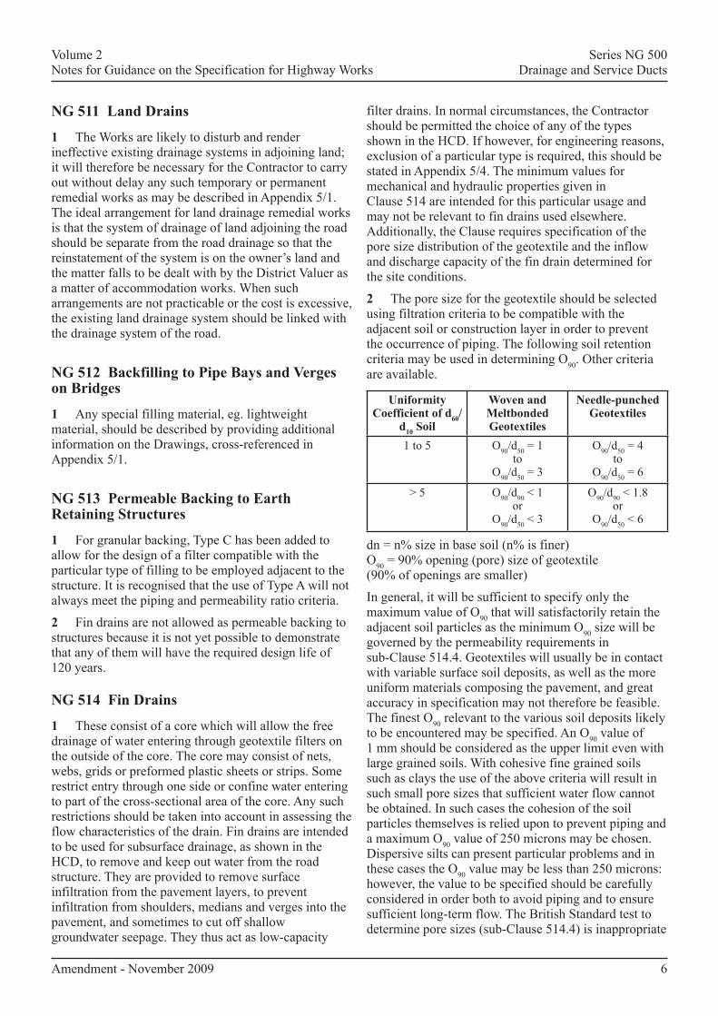
2 Theporesizeforthegeotextileshouldbeselectedusingfiltrationcriteriatobecompatiblewiththeadjacentsoilorconstructionlayerinordertopreventtheoccurrenceofpiping.ThefollowingsoilretentioncriteriamaybeusedindeterminingO90.Othercriteriaareavailable.
uniformity coefficient of d60/
d10 Soil
Woven and Meltbonded Geotextiles
Needle-punched Geotextiles
1to5 O90/d50=1to
O90/d50=3
O90/d50=4to
O90/d50=6
>5 O90/d90<1or
O90/d50<3
O90/d90<1.8or
O90/d50<6
dn=n%sizeinbasesoil(n%isfiner)O90=90%opening(pore)sizeofgeotextile(90%ofopeningsaresmaller)
Ingeneral,itwillbesufficienttospecifyonlythemaximumvalueofO90thatwillsatisfactorilyretaintheadjacentsoilparticlesastheminimumO90sizewillbegovernedbythepermeabilityrequirementsinsub-Clause514.4.Geotextileswillusuallybeincontactwithvariablesurfacesoildeposits,aswellasthemoreuniformmaterialscomposingthepavement,andgreataccuracyinspecificationmaynotthereforebefeasible.ThefinestO90relevanttothevarioussoildepositslikelytobeencounteredmaybespecified.AnO90valueof1mmshouldbeconsideredastheupperlimitevenwithlargegrainedsoils.Withcohesivefinegrainedsoilssuchasclaystheuseoftheabovecriteriawillresultinsuchsmallporesizesthatsufficientwaterflowcannotbeobtained.InsuchcasesthecohesionofthesoilparticlesthemselvesisreliedupontopreventpipingandamaximumO90valueof250micronsmaybechosen.DispersivesiltscanpresentparticularproblemsandinthesecasestheO90valuemaybelessthan250microns:however,thevaluetobespecifiedshouldbecarefullyconsideredinorderbothtoavoidpipingandtoensuresufficientlong-termflow.TheBritishStandardtesttodetermineporesizes(sub-Clause514.4)isinappropriate
Amendment-November2009 6

Volume2 SeriesNG500NotesforGuidanceontheSpecificationforHighwayWorks DrainageandServiceDucts
forsomegeotextiles,suchasneedle-punchedmaterials,ifmorethan20%oftheglassbeadsareretainedinthefabric.Poresizesmustthenbeobtainedbyothermeanssuchaswetsieving.
3 (05/04)Sub-Clause4(v)ofClause514requiresthedesignertospecifytheflowratenormaltothegeotextilewrappingtothefilterdrain.Thespecifiedflowrateshouldincorporateamarginofsafetytoallowfortheimpededflowduetotheadjacentcoreofthefindrain(orthefiltermaterialinanarrowfilterdrain)asdescribedinsub-Clause13ofClause514.Itshouldalsoincorporateasubstantialmargintoallowforthereductionofflowwithtimeduetoclogging.Thelong-termflowthroughageotextileincontactwiththecoarsegravelmaynotdiffersignificantlyfromtheshort-termflowmeasuredinthestandardtest.Incontrast,thelongtermflowthroughageotextileincontactwithadispersivesiltmaybeonethousandtimessmallerthantheshort-termflow.Thereissomeevidencethatchemicalorbiologicalleachatesmayalsocausesevereclogging.
Differentratesofflowintothetwosidesofthefindrainmaybespecified,forexample,ifthewaterflowsfromthevergesareexpectedtobeverydifferenttothosefromthepavementstructure.Avalueof10litres/m2/secissuggestedforuseagainsttheunboundmixtureforsubbaseandcappingspecifiedinSeries600and800.Verymuchsmallervaluesareadequateforsoilsandbackfillsotherthancoarsegravels,andpossiblydispersivesiltsorcontaminatedsites.Itshouldbeappreciatedthat,becauseofsuchlong-termeffects,theseflowratesshouldnotbeusedtodeterminethein-planedesignrequirementsofthefindrain.
4 Sub-Clause5ofClause514requiresspecificationofthein-planeflowcapacityofthefindrain.Thisdesigncapacityshouldallowforinfiltrationthroughthepavementandvergesandanyothersourceofgroundwateringress.Untilmoreaccuratemeansofestablishinginfiltrationratesthroughthepavementareavailableavaluenotlessthanthemeanintensityofaoneyear2hourrainfallshouldbeassumed.ThefindrainType5ofDrawingF18intheHCDactsbothasafilterdrainandacarrierpipe.Thusin-planeflowmustbespecifiedforflowbothalongthedrainparalleltotheroadedgeandnear-verticallydownthedrain.Forallotherdraintypes,onlynear-verticaldownwardflowneedbespecified.FindrainType10inDrawingF21shouldeitherhaveanimpermeablesideorbecoveredbyanimpermeablemembraneunlessnosignificantblockingofthecorewilloccurduringtheslip-formingofthechannel.
Findrainsarenormallylaidatconstantdepthbelowthecarriagewayandtheirgradientwillthereforefollowthatoftheroad.Drainagecapacitiesshouldbedesignedforthesegradientsandoutfalllengthsdetermined
accordingly.FordrainType5theflowratesthatarestatedinAppendix5/4shouldbethecapacityrequiredlinearlyextrapolatedtothestandardgradientsinTable5/8.Wherefindrainsutiliseapipe,capacitiesmaybeobtainedfromhydraulictablesandtherequireddiameterspecified.
5 Sub-Clause9ofClause514specifiestheuseofas-dugmaterialfortrenchbackfill.Ifthismaterialwhencompactedissufficientlylesspermeabletoaffecttheefficiencyofthedrain,orcontainsstoneslargerthanabout100mmwhichcoulddamagethedrain,analternativematerialcompatiblewiththegeotextileshouldbeused.
6 Properfunctioningofthefindrainanditsancillarycomponentsdependscriticallyonadequateinstallationandjoiningprocedures.
Findrainscanbeproblematicalduringconstructionphaseforthefollowingreasons.
i (05/04)Theydonotprovideimmediatedrainagefortheunpavedsubbase.
ii Theyarenotdesignedforsurfacewaterflows.
iii Fineparticlestransportedbysurfacewaterorvehiclesmayclogthefilterorsiltthedrain.
iv Theymaybedamagedbythepassageofconstructiontraffic.
Appropriateprotectionmeasuresmustbetaken,egpolythenesheeting,temporarydrainagechannels,orwarningfence.Alternatively,thedrainsmaybeinstalledtowardstheendoftheconstructionphase.
7 AllfindrainsandtheirconstituentsmustbethesubjectofaBritishBoardofAgrémentRoadsandBridgesCertificatewhichcertifiesthevaluesachievedforthespecifiedpropertieswhentestedinaccordancewithClause514.Findrainsareavailableinavarietyofconfigurationswithdifferenttypesofcorestructure.Inaddition,severaltestsdescribedinClause514aremodifiedBritishStandardtestsorhavebeendevelopedespeciallyfortheSpecificationandasyetthereislittleexperienceoftheiruse.Thesetwofactorsmeanthatsomevariationorinterpretationofthetestmethodmaysometimesbenecessary.TheBritishBoardofAgrémentwillagreedetailsofanyappropriatevariationsinthespecifiedtestmethodsfollowingconsultationwiththemanufacturer.ItisintendedthatwhenevertheContractorproposestheuseofanyfindrainorconstituentmaterialhemustsupplycopiesoftheappropriateBritishBoardofAgrémentRoadsandBridgesCertificatetoconfirmthatthematerialcomplieswiththeContractrequirements.(FurtherguidancemaybesoughtfromtheOverseeingOrganisation.)
Amendment-November2009 7
Volume2 SeriesNG500NotesforGuidanceontheSpecificationforHighwayWorks DrainageandServiceDucts
NG 515 Narrow Filter drains
1 Narrowfilterdrainsareintendedforuseasedgeofpavementsub-surfacedrainsandaresuitablealternativestofindrainsforthispurpose.BothtypeshavethesamerequirementsofperformanceandtheguidancegiveninNG514isequallyapplicabletodeterminingthesoilretentionandpermeabilitycriteriaofthegeotextileusedinnarrowfilterdrainsandtothedischargecapacityofthedrain.Innormalcircumstances,theContractorshouldbepermittedthechoiceofanyofthetypesshownintheHCD.Ifhowever,forengineeringreasons,exclusionofaparticulartypeisrequired,thisshouldbestatedinAppendix5/4.
2 IndrainType8thefiltrationfunctionisachievedbyagranularfiltermaterialandgeotextilesockandinType9bymeansofageotextilewrappingtothedrain.Bothfiltersshouldbedesignedtobecompatiblewiththeadjacentsoilorconstructionlayer.FortheType8draingranularmaterialthevalueofD15tobespecified(Table5/8)shouldbebasedonthecriteriaD15Flessthanorequalto5xD85S(TRRLReportLR346)whereD85Sisthesievesizepassing85%byweightoftheadjacentsoil.Thegeotextilesockroundthepipeisasecondstagefilterwhereitisrequiredtoretaintheparticlesofthefirststagegranularmaterial.However,thepipewhenlaidinthenarrowtrenchmayhaveinsufficientgranularsurroundforfullyeffectivefirststagefiltrationtobeachieved.Poresizesforthesockmaterialshouldthereforebedesignedtoalsoretainthefinersoilparticlesoutsidethetrench.
3 ThespecificationforgranularmaterialinTable5/8isintendedtopermitthewidestrangeofavailablematerialtobeused.Theselimitshavebeensettoreducetheriskofdamagetothegeotextile,toavoidgapgradingofthefiltermaterialandtoensureanadequatedegreeofpermeability.Forthematerialasspecifiedaminimumvalueofpermeabilityofabout1x10-4m/secondwhichissimilartothatobtainedbyacleancoarsesandmaybeassumed.AhigherpermeabilitywillrarelybenecessarybutifrequireditmaybespecifiedinAppendix5/4.
4 Narrowfilterdrainsrequireprotectionduringtheconstructionphasesimilartothatprovidedforfindrains(seeNG514.6).
5 ThegeotextilesusedinnarrowfilterdrainsrequireBritishBoardofAgrémentRoadandBridgescertification(seeNG514.7).
NG 516 combined drainage and Kerb Systems
1 TheDrawingsshouldshowthelocationandgradient(s)ofthecombineddrainageandkerbsystem,thepositionofaccess,silttrap,outfallandendunitstogetherwiththepositionandinvertlevelofthesurfacewateroutfallconnection.Thepositionofanymovementjointsrequiredinthesystem,eg.atjointsinbridgedecksorconcretecarriageways,shouldbeshown.Detailsofanyducts,cabling,etc,requiredtopassunderthekerbshouldbeshown.TheextentoftheworktobedesignedbytheContractorshouldbeclearlydefined.
2 CombineddrainageandkerbsystemsshouldbescheduledinAppendix1/11andcross-referencemadetothedesignrequirementsgiveninAppendix5/5.
3 (05/01)AdviceonthelocationofClassCandClassDsystemsisgiveninsub-ClauseNG517.1.
NG 517 Linear drainage channel Systems
1 (05/04)ThelineardrainagechannelsspecifiedinClause517maybeusedintrunkroadsincludingmotorways.ClassDchannelsaredesignedtowithstandloadingsofalltypesofroadvehiclethatarepermittedontrunkroadsincludingmotorways.ClassCchannelsshouldonlybeinstalledinlocationswhichareprotectedfromdirecttrafficloading,eg.inareasbehindsafetybarriers.TherangeofslotdimensionspermissiblewithinClause517isnotcompatiblewithsafeusagebycyclistsandpedestrians,andunitswithslotdimensionsdescribedinClause517shouldnotbeusedinareassubjecttosuchtraffic.
2 TheDrawingsshouldshowthelocationofthelineardrainagesystemsandthepositionsofthesurfacewateroutfallchambersintowhichthesystemsaretooutfall.Thepositionofanymovementjointsrequiredinthesystem,eg.atjointsinbridgedecksorconcretecarriageways,shouldbeshown.Detailsofanyducts,cabling,etc.,requiredtopassunderthesystemsshouldbeshown.TheextentoftheworktobedesignedbytheContractorshouldbeclearlydefined.
3 LineardrainagechannelsystemsshouldbescheduledinAppendix1/11andcrossreferencemadetothedesignrequirementsgiveninAppendix5/6.
4 Variationstostateddimensionsmaybeconsideredprovidingthattheproductwillmeettherequirementsofthisspecification.
5 Asystemcomprisingunitswhichmaybeotherwisetoosmalltoaccommodatedesignflowswithoutsurchargemaybeacceptableinconjunctionwiththeprovisionofadditionalintermediateorupstreamchamberssubjecttothefollowingrequirements:
Amendment-November2009 8

Volume2 SeriesNG500NotesforGuidanceontheSpecificationforHighwayWorks DrainageandServiceDucts
a) IntermediatechambersshouldbecompatiblewiththestandardsofthechambersshownontheDrawingsandanylongitudinaldrainsconnectingsuchchambersshouldalsobeconnectedintotheintermediatechambers.
b) NotmorethanoneintermediatechambershouldbepermittedbetweentheupstreamanddownstreamchambersofanydrainshownontheDrawings.
c) NotmorethanoneadditionalchambershouldbepermittedupstreamofeachupstreamchambershownontheDrawings.
NG 518 (05/01) thermoplastics Structured Wall Pipes and Fittings
General
1 WherethermoplasticsstructuredwallpipesandfittingsareincludedintheschedulesofpermittedalternativesinAppendix5/1,thematerialpropertiesrequiredofthedifferentpipematerialsshouldbespecifiedbythemanufacturerintheformatgiveninAppendix5/7.Thethirdpartycertificationbodyverifiesthesepropertiesagainstthedeclaredspecification.Fulfilmentoftheperformancerequirementsinconjunctionwithmaintainingthematerialspecificationshouldprovidetherequireddurabilityfortheproduct(ieaminimumlifeof45years).
Materials
2 Mostthermoplasticsarestableagainstcommonchemicalsfoundingroundwaterandinsurfacewaterrunoff.FurtherdetailsonthesuitabilityofaparticularcompoundcanbefoundinCP312:1976.ThepipesandfittingsshouldbeprotectedagainstprolongedexposuretosunlightanditmaybenecessaryfortheContractortocoverthepipespriortoinstallation.
dimensions
3 DimensionsshouldbemeasuredinaccordancewithprENISO3126andshouldfulfiltherequirementsofsub-Clause518.3andthedeclaredspecification(seeAppendix5/7).
appearance
4 TheboreofthepipefittingsshouldbesmoothtoallowthecorrectchoiceofManning’scoefficientforhydraulicdesignofthesystem.
Structured Wall Pipe
5 Table5/9givestherequirementsforstructuredwallpipes.WherereferenceismadetoBritish,EuropeanorInternationalStandards,thesestandardsshouldbeconsultedtodiscerntherelevanttestconditionsfortheproduct.Wherenostandardtestmethodisavailable,thetestmethodisdescribedinsub-Clauses518.11to518.13.Additionalinformation,isgiveninTableNG5/1.
Amendment-November2009 9
taBLE NG 5/1(11/03)additional Information for Structured Wall Pipe
Property additional InformationGeneral QualitycontrolandidentificationRingstiffness Manufacturer’sminimumspecificationisrequiredforcalculationtoBSEN1295CreepRatio Manufacturer’smaximumspecificationisrequiredforcalculationtoBSEN1295.
Note:thelongtermringstiffnessusedfordesignpurposesisthetwoyearstiffnessandiscalculated1bydividingtheringstiffnessbythecreepratio
Highvolumelowpressurejetting Apassisdeemedtoalsoestablishsatisfactoryperformanceathighvolumeandlowpressure
Longitudinalbending ToreducethepossibilityofproblemscausedbyhandlingonsiteImpactresistanceat0°C Thed50strikerisnon-standardImpactresistanceat23°C ForqualitycontrolonlyRoddingresistance TosimulateeffectsofdrainroddingCreepatelevatedtemperature(ducts) Tosimulatetheeffectofexposuretohightemperaturesthatmayoccurinpowercable
ductsResistancetopointloads(ducts) Simulatesharpaggregatepenetration
Note1: WhencarryingoutcalculationstoBSEN1295theminimumvalueforstiffnessandthemaximumvalue ofcreepratioshouldbeusedinordertoestablishthelongtermstiffness.Forexample,apipemighthave adeclaredminimumstiffnessof4.5andamaximumdeclaredcreepratioof3.8.Thelongtermstiffness wouldbe4.5/3.8=1.18kN/m2.Site-specificcalculations,inaccordancewithBSEN1295,canbeused toestablishthatthelongtermdeformationwillbelessthan5%andthesafetyfactoragainstbuckling greaterthantwo.
Volume2 SeriesNG500NotesforGuidanceontheSpecificationforHighwayWorks DrainageandServiceDucts
Fittings
6 Asstatedinsub-Clause5ofthisClausethestandardsshouldbeconsultedtodiscerntherelevanttestconditionsfortheproductagainsttherequirementsgiveninTable5/10.
Installation and Handling
7 (05/04)Careshouldbetakentopreventchangesinlineorlevelwhenplacingthesurroundmaterialoverthepipecrown,asthereisthepossibilityofflotation(seealsosub-Clause503.6).Compactionlevelsofallsidefillandbackfillmaterialmustbecloselymonitoredasthesehaveadirectimpactonthegroundsettlementandpipedeflectioncharacteristics.Specialprecautionsmaybenecessarywherethesystemissubjecttohighconstructionloadingsuchasspreaderplates.
8 Installationandcompactionofthepipeandsurroundarekeytotheperformanceanddurabilityofthesystem.Thepipemustbeinstalledtolineandlevelandanypipethatisoutofshapeshouldnotbeinstalled.Thechangeinshapecouldbecausedby,longitudinalbending,mechanicaldamageordeformationunderliftingandinstallation.Largerdiameterpipesandfittingsmustbehandledwithcareastheyaremorelikelytosufferimpactdamageespeciallyatlowertemperatures.ReferenceshouldbemadetotheHSEManualHandlingOperationsRegulations1992guide‘GuidanceonRegulationsL/231998’,whereappropriate,andcaretakenwhilstusingmechanicalplantespeciallyneartotrenchwalls.ThemanufacturermustsupplytheweightpermetreofthepipeandfromthisinformationtheContractorisabletoassesstheliftingneedsforinstallationofthepipe.
test Method for Longitudinal Bending
9 Thetestisintendedtoeliminateveryflexiblepipe(egcoilablepipe)andpipewhichissoweakthatitmightdeformwhilstbeinghandledonsite.
10 Thetwolevelsupportblocksatleast250mmwideandofsufficientheighttoallowthepipetosagoveritslengthwithouttouchingthegroundcouldconsistofstandardbuildingblocksstoodontheirends.
test Method for Rodding Resistance (Internal Puncture)
11 Thetestisintendedtosimulatedamagewhichmightbecausedbytheferruleofadraincleaningrodbeingimpactedagainsttheinsideofthepipeorfittingduringcleaningoperationsandisintendedtoensurethestructuralintegrityoftheinnerlayer.Asegmentofpipeorasectionfromafittingissubjectedtoimpactonitsinternalsurfacewhilstfullysupportedbyitsexternalsurface.
test Method for Resistance to Sharp Objects
12 Thetestisintendedtosimulatetheeffectofpenetrationduetosharpaggregateandisintendedtoexcludeductswithparticularlythinwallsection.
NG 521 (11/03) Low Pressure High volume Jetting of drainage Systems
General
1 ThedrainagesystemtobecleanedshouldbestatedinAppendix5/1.Thedetailsshouldincludethelocations,typeofpipematerial,whereknown,pipediameterorstatethetypeofsystemifnotpiped.
2 Wherepitchfibre,porousconcreteorperforatedpipesareknowntobepresent,theseshouldbeidentifiedinAppendix5/1andtheContractormadeawareoftheirpresence.
3 IftheWorksarerequiredtobedetailedinaccordancewithAppendix90/1ofSeries9000(MCHW5.9.3),theCompiler’sattentionisdrawntotheneedtoensurealsothattherelevantsectionsoftheMethodofMeasurementfortheSeries9000areincluded(andamendedifnecessary)withintheschemespecificdocuments.
Jetting of Piped drainage Systems
4 Analternativemethodofcleaningshouldbeusedforporousconcreteorperforatedpipes.Thereisarisktothestructuralintegrityoftheporouspipesandariskthatexfiltrationwillentertheunboundpavementlayersandwashoutfinematerialinbothinstances.Thismaycausevoidstoformandresultinprematurepavementfailure.Pitchfibrepipesshouldbetreatedas“unknown/structurallydamaged”inaccordancewithTable5/12.
Jetting of Linear drainage Systems
5 ThetypeoflineardrainagesystemshouldbedetailedinAppendix5/1.
6 Theuseofahighpressurelancemaybeusedexternallytocleargratingsorslotsoflineardrainagesystems.
Silt Removal
7 Thepipelineshouldbedeemedtobecleanwhenthesiltcontentofthecross-sectionalareaofthepipeisbetween0and10%forpipes≤600mmandbetween0and5%forpipes>600mmdiameter.
Amendment-November2009 10
Volume2 SeriesNG500NotesforGuidanceontheSpecificationforHighwayWorks DrainageandServiceDucts
Health and Safety
8 (11/05)TheContractorshouldundertaketheworksinaccordancewiththeHealthandSafetyatWorketcAct(1974),theConstruction(Health,SafetyandWelfare)Regulations(1996)andEN1829:Highpressurecleaners,Highpressurewaterjetmachines-Safetyrequirements.Thesafetyaspectstobeaddressedrelatingtojettingare,practicesconcerninghighpressurewater,possibleinfectionfromthedraincontents,workingonthehighwayandinsomecircumstances,workinginconfinedspaces.
Equipment
9 Jetheadswithnozzlessetatapproximately20otothepipesurfacehavealowjetangleandareunlikelytocausedamagetothepipeline.Fanjetshavelowjetanglesandarewidelydissipatedandhenceunlikelytocausedamagetothepipeline.
Amendment-November2009 11F

Volume2 SeriesNG500NotesforGuidanceontheSpecificationforHighwayWorks DrainageandServiceDucts
NG SaMPLE aPPENdIX 5/1: (05/01) dRaINaGE REQuIREMENtS[Note to compiler: This should include:]1 (11/06)thebasisofthehydraulicdesignofthesystemonwhichtheContractorshouldsubmithisproposalsfor
pipetypesandmakes[501.3, 8005.1];2 (11/06)ascheduleofpermittedalternativepipeandbeddingcombinations;[which should be determined in
accordance with Advice Note HA 40 (DMRB 4.2.5)] [503.3, 8005.7]andlistofpipelinestobeconstructedotherthaninatrench[608.8];
3 (05/04)gradingandgeometricalrequirementsforfilterdrainmaterialTypeC;
4 valuesofpipestiffnessclass,creepratioandimpactresistanceforthermoplasticspipes;
5 platethicknessesforboltedsegmentalplatepipes[501.4(i)]andminimumplatethicknessforcorrugatedsteelpipesoflockseamfabricationifdifferentfromsub-Clause501.4;
6 whethercorrugatedsteelpipesaretohaveadditionalprotectionofhot-appliedbitumen[501.5];7 wheresulfate-resistingPortlandcementisrequiredforconcretepipes [Table 5/1];8 pipeclassificationtoBS5480forGRPpipesfordrainage[Table 5/1];9 layingmethodforcorrugatedcoilableperforatedpipes[503.2]10 detailsofmaterialsifdifferingfromtherequirementsofsub-Clause503.3(v);11 (11/03)whetherjointsinsurfacewaterdrainsshouldbewatertightorpartlywatertight[504.2];12 whererigidjointsmaybeused[504.3]13 (05/04)backfillingrequirementsdifferingfromsub-Clause505.2;referencestodrawingsgivinglocationswhere
backfillingisrequiredtoalevelotherthanthatspecifiedinsub-Clause505.8;
14 wheresaddlesmaybeused[508.7 and 508.7NI]15 materialclassificationforbackfillingfilterdrainsandpermeabilityrequirementsincludingtestdetails[509.8];16 (11/06)referencestodrawingsshowingrequirementsforconnectingexistingdrainstonewdrainsanddetailsof
specialconnectingpipes[506.1, 8005.19];17 requirementsforsealing,removalorgroutingofexistingdrains[506.3];18 detailsofconnectingexistinglanddrains[511.1];19 whetherseveredmoledrainsaretobeinterceptedbyconstructionofalanddrain[511.4];20 requirementsforbackfillingmolechannelsifdifferentfromtherequirementsofsub-Clause511.4;21 referencestodrawingswhichshowchambertypes[507.1];22 (11/04)particularrequirementsforprecastandcastin-situchambersifdifferingfromtherequirementsof
sub-Clause507.4[507.4];23 particularrequirementsforcorrugatedgalvanizedsteelchambers[507.5];24 (11/04)requirementsfortestingchambersforfoulandsurfacewaterdrainsforwatertightness[507.8]and
carrier,foulandfilterdrainsurveysbyClosedCircuitTelevision(CCTV)[this requirement to be stated in Appendix 90/1 (MCHW 9.5.3)] [509.5];
25 (11/09)detailsofchambercovers,gratingsandframes[507.9]anddetailsforspecialdutycoversforuseincarriageways[507.13];requirementsforminimumwaterwayareatogratingsforcatchpits[507.14];PolishedSkidResistanceValue(PSRV)forchambercovers[507.9];
26 theclassesandsizesofcastironandsteelgullygratings[508.4];
Amendment-November2009 A1

Volume2 SeriesNG500NotesforGuidanceontheSpecificationforHighwayWorks DrainageandServiceDucts
27 requirementsforgullygratingsifdifferentfromtherequirementsofsub-Clause508.5;28 requirementsforsettingexistingcoversandgratingstolevelifdifferentfromtherequirementsofsub-Clauses
507.18and508.8;
29 (05/06)whethergulliesaretobetrapped,untrappedorsumpless[508.1];detailsofinsituconcretegullies[508.3];
30 referencestodrawingsshowingrequirementsforfillingtopipebaysandvergesifdifferentfromtherequirementsofsub-Clause512.1;
31 requirementsforpermeablebackingifdifferentfromtherequirementsofsub-Clauses513.1and513.2;32 requirementsforthecleaningofchambers,gulliesanddrains [509.5];33 (11/03)requirementsforcleaningofexistingdrainagesystems-Clause520[520.1 and 520.4];34 requirementsforrapidsettingbeddingmaterialsandthelocationswheretheywillberequired[507.18];35 (11/03)requirementsforthecleaningofexistingdrainagesystemsusinglowpressurehighvolumejetting
[521.1];detailsofdrainagesystem[521.2]andpipematerial[521.3];36 (05/04)limitingdistancefordepositionofmaterialsreferredtoinsub-Clauses503.4,503.5,505.4and505.5.
37 (05/06)requirementsforgeotextiles[HCD - Drawing B15].
NG SaMPLE aPPENdIX 5/2: (05/01) SERvIcE duct REQuIREMENtS[Note to compiler: This should include:]1 (05/04)detailsofductconstruction[503.7] [cross-reference should be made to HCD drawing no. I2 where appropriate];2 ascheduleofserviceductrequirements[similar to those in Appendix 5/1 for pipes];3 (05/04)detailsofpermanentmarkerblocksandlocationpostsrequiredforserviceducts[505.9] [cross- reference should be made to HCD drawing no. I1 where appropriate].4 colourcodingofducts[Refer to 501.7, 518.4 and Health and Safety Executive booklet HS(G)47];5 referencestodrawingswhichshowchambertypes[501.8].
NG SaMPLE aPPENdIX 5/3: SuRFacE WatER cHaNNELS aNd dRaINaGE cHaNNEL BLOcKS(11/04)[Note to compiler: State here specific requirements cross-referring to the appropriate drawing numbers, including HCD Series B and F drawings as listed in Appendix 0/4 of the Contract document] [510.1]
Amendment-November2009 A2

Volume 2Notes for Guidance on the Specifications for Highway Works
Series NG 500Drainage and Service Ducts
A3
NG SAMPLE APPENDIX 5/4: FIN DRAINS ANDNARROW FILTER DRAINS
[Note to compiler: This should include:]1 Permitted alternative types of fin drain and narrow filter drain.
[Normally the choice of type of fin or narrow filter drain should be left to the Contractor.]2 Drawing references showing locations.
3 The maximum permissible O90 determined from the pore size distribution curve of the geotextile [514.4(iv)and 515.3].
4 The permeability of the geotextile [514.4(v) and 515.3].
5 The long term in-plane flow for fin drains [514.5].
6 Pipe diameters [514.10 and 515.6].
7 Trench backfill material for fin drain if not as-dug material [514.9].
8 D15 particle size for granular material in narrow filter drain Type 8 [515.5].
9 Permeability of granular material in narrow filter drain where required [515.5].
10 (11/03) Maximum drain slope angle if different from 15% [514.10 and 515.6].
11 Dimensions of fin drains and narrow filter drains if different from the requirements of sub-Clauses 514.10 and515.6.
12 References to drawings and/or schedules which show required levels [514.11 and 515.7].
Amendment - November 2003

Volume 2Notes for Guidance on the Specifications for Highway Works
Series NG 500Drainage and Service Ducts
A4
NG SAMPLE APPENDIX 5/5: COMBINED DRAINAGEAND KERB SYSTEMS
[Note to compiler: Include here:]1 Drawing references showing locations, etc.
2 Limiting dimensions:
(i) (11/04) Maximum width and depth of units [if applicable] [516.4].
(ii) Kerb upstand.
(iii) Kerb profile [if applicable].
(iv) (11/04) dimensions of side-entry inlets of units to be used in or adjacent to porous asphalt [516.5].
3 (11/04) Strength requirements[units must be specified as class D or class C. Class D units must be used where there is a possibility of impactfrom all types of road vehicle that are permitted on trunk roads including motorways. Class C units must onlybe installed in locations which are protected from direct traffic loading, eg. in areas behind safety barriers.Further advice on other permitted classes can be found in clause 5 of BS EN 1433.] [516.6]
4 (11/04) Hydraulic design parameters [516.1 and 516.3]5 (11/04) Any special fittings required [516.10].
Amendment - November 2004

Volume 2Notes for Guidance on the Specifications for Highway Works
Series NG 500Drainage and Service Ducts
A5
NG SAMPLE APPENDIX 5/6: LINEAR DRAINAGECHANNEL SYSTEMS
(11/04) [Note to compiler: Include, as appropriate, the various requirements for the prefabricated and the in-situlinear drainage channel systems here:]1 Drawing references showing locations, etc.
2 Limiting dimensions:
i) (11/04) maximum width and depth of units [517.4 and 1103.1]ii) (11/04) dimensions of side-entry inlets of units to be used in or adjacent to porous asphalt [517.5]
3 (11/04) Hydraulic design parameters [517.1 and 517.3]4 (11/04) Strength requirements
[units must be specified as class D or class C. Class D units must be used where there is a possibility ofimpact from all types of road vehicle that are permitted on trunk roads including motorways. Class C unitsmust only be installed in locations which are protected from direct traffic loading, eg. in areas behind safetybarriers. Further advice on other permitted classes can be found in clause 5 of BS EN 1433.] [516.6]
5 (11/04) Weathering Resitancerequirement relating to the grade of weathering resistance for drainage channels made of concrete[see clause 6.3.3.3 of BS EN 1433] [517.7]
6 (11/04) Any special fittings required [517.9].
Amendment - November 2004

Volume 2Notes for Guidance on the Specifications for Highway Works
Series NG 500Drainage and Service Ducts
A6
NG SAMPLE APPENDIX 5/7: (05/01) THERMOPLASTICSSTRUCTURAL WALL PIPES AND FITTINGS
Information to be provided by the Contractor
The Contractor shall provide the following information, in accordance with sub-Clause 518.2, for the range ofpipes and fittings (to be verified by the Certification body - see sub-Clause 518.15):
1 Technical drawings showing dimensions and tolerances including sealing rings and weight per metre, togetherwith properties, as specified in sub-Clauses 518.3 and 518.5.
2 Material specification, as required in sub-clause 518.2:
Table 1: (11/03) Unplasticised polyvinyl-chloride (PVC-U)
Property Test method reference Specification
Tensile Properties BS EN ISO 6259,BS EN ISO 527-1
Vicat BS EN 727
Longitudinal reversion BS EN 743
K-value BS EN 922
PVC content EN 1905
Density BS EN ISO 1183-3, ISO 4451
Heat Reversion ISO 12091
Effects of heating (injectionmoulded fittings only) BS EN 763
Table 2: (11/03) Polyethylene (PE)
Property Test method reference Specification
Tensile Properties BS EN ISO 6259,BS EN ISO 527-1
Oxygen induction time BS EN 728
Melt Flow Rate BS EN ISO 1133
Density BS EN ISO 1183-3, ISO 4451
Melt Flow Rate ISO 4440
Heat Reversion ISO 12091
Effects of heating (injectionmoulded fittings only) BS EN 763
Amendment - November 2004

Volume 2Notes for Guidance on the Specifications for Highway Works
Series NG 500Drainage and Service Ducts
Table 3: (11/03) Polypropylene (PP)
Property Test method reference Specification
Tensile Properties BS EN ISO 6259,BS EN ISO 527-1
Oxygen induction time BS EN 728
Melt Flow Rate BS EN ISO 1133
Density BS EN ISO 1183-3, ISO 4451
Heat Reversion ISO 12091
Effects of heating (injectionmoulded fittings only) BS EN 763
A7FAmendment - November 2004