
Series - YUKEN ASR Series AC Servo Motor Driven Pumps MPG M O “PS” Controller (Computing Unit)...
24
Pub.EC-1905-1 Series
Transcript of Series - YUKEN ASR Series AC Servo Motor Driven Pumps MPG M O “PS” Controller (Computing Unit)...

Pub.EC-1905-1
Series

1 ASR Series AC Servo Motor Driven Pumps
Hydraulic Fluids
Instructions
■ Hydraulic Fluids
Use clean petroleum base oils equivalent to ISO VG32 or 46. The recommended viscosity range is from 20 to 400 mm2/s and temperature range is from 0 to 60 ℃ , both of which have to be satisfied for the use of the above hydraulic oils.
■ Control of Contamination
Due caution must be paid to maintaining control over contamination of the operating oil which can otherwise lead to breakdowns and shorten the life of the unit. Please maintain the degree of contamination within NAS class 9.The suction port must be equipped with at least 100 μm (150 mesh) reservoir type filter and the return line must have a line type filter of under 10 μm.
■ Transportation
For transportation, use the lifting rings on the pump. Do not use lifting cables at places other than the lifting rings.
■ Mounting
When installing the pump, the filling port should be positioned upwards.
■ Suction Pressure
Permissible suction pressure at the inlet port of the pump is between -16.7 and +50 kPa. For piping to the suction port, use pipes of the nominal diameters shown below. Make sure that the height of the pump suction port is lower than the oil level in the reservoir.
Model Nominal Dia.
ASR 1 / ASR 2 3/4
ASR 3 / ASR 5 1 1/4
ASR10 2
■ Hints on Piping
When using steel pipes for the suction or discharge ports, excessive load from the piping to the pump generates excessive noise. Whenever there is fear of excessive load, please use rubber hoses.
■ Drain Piping
Install drain piping according to the chart and ensure that pressure within the pump housing should be maintained at a nominal pressure of less than 0.1 MPa and surge pressure of less than 0.5 MPa.The length of piping should be less than 1 m. Instead of joining the drain pipe to other return lines, run it independently. The pipe end should be submerged in oil.
[Recommended Drain Piping Size]
Model Fitting Size Inside Dia. of Pipe
ASR 1 / ASR 2 3/8 (Inside Dia. 8.5 mm or more) 10 mm or more
ASR 3 1/2 (Inside Dia. 12 mm or more) 12 mm or more
ASR 5 / ASR10 3/4 (Inside Dia. 16 mm or more) 19 mm or more
2ASR Series AC Servo Motor Driven Pumps
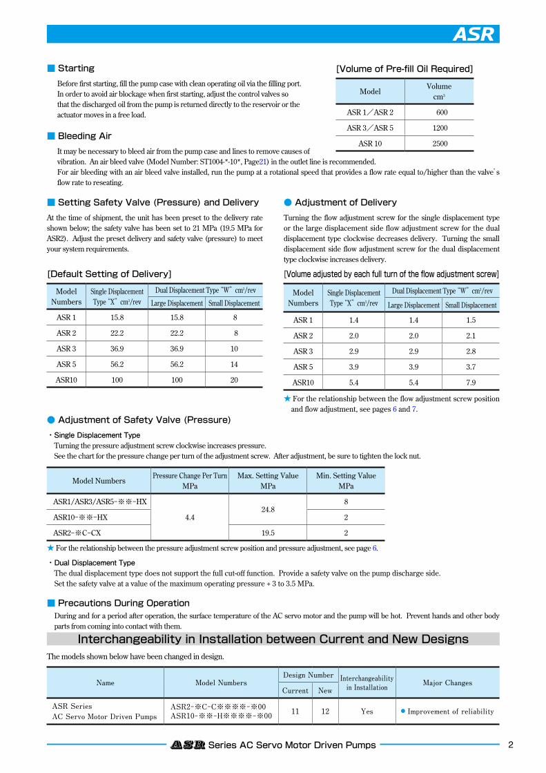
■ Starting
Before first starting, fill the pump case with clean operating oil via the filling port. In order to avoid air blockage when first starting, adjust the control valves so that the discharged oil from the pump is returned directly to the reservoir or the actuator moves in a free load.
■ Bleeding Air
It may be necessary to bleed air from the pump case and lines to remove causes of vibration. An air bleed valve (Model Number: ST1004-*-10*, Page21) in the outlet line is recommended.For air bleeding with an air bleed valve installed, run the pump at a rotational speed that provides a flow rate equal to/higher than the valve’s flow rate to reseating.
[Default Setting of Delivery]
■ Setting Safety Valve (Pressure) and Delivery
At the time of shipment, the unit has been preset to the delivery rate shown below; the safety valve has been set to 21 MPa (19.5 MPa for ASR2). Adjust the preset delivery and safety valve (pressure) to meet your system requirements.
● Adjustment of Delivery
Turning the flow adjustment screw for the single displacement type or the large displacement side flow adjustment screw for the dual displacement type clockwise decreases delivery. Turning the small displacement side flow adjustment screw for the dual displacement type clockwise increases delivery.
● Adjustment of Safety Valve (Pressure)
・Single Displacement Type Turning the pressure adjustment screw clockwise increases pressure. See the chart for the pressure change per turn of the adjustment screw. After adjustment, be sure to tighten the lock nut.
・Dual Displacement Type The dual displacement type does not support the full cut-off function. Provide a safety valve on the pump discharge side. Set the safety valve at a value of the maximum operating pressure + 3 to 3.5 MPa.
■ Precautions During OperationDuring and for a period after operation, the surface temperature of the AC servo motor and the pump will be hot. Prevent hands and other body parts from coming into contact with them.
[Volume adjusted by each full turn of the flow adjustment screw]
[Volume of Pre-fill Oil Required]
★ For the relationship between the flow adjustment screw position and flow adjustment, see pages 6 and 7.
★ For the relationship between the pressure adjustment screw position and pressure adjustment, see page 6.
ModelVolume
cm3
ASR 1/ASR 2 600
ASR 3/ASR 5 1200
ASR 10 2500
ModelNumbers
Single Displacement Type “X”cm3/rev
Dual Displacement Type “W”cm3/rev
Large Displacement Small Displacement
ASR 1 15.8 15.8 8
ASR 2 22.2 22.2 8
ASR 3 36.9 36.9 10
ASR 5 56.2 56.2 14
ASR10 100 100 20
Model Numbers
Single Displacement Type “X”cm3/rev
Dual Displacement Type “W”cm3/rev
Large Displacement Small Displacement
ASR 1 1.4 1.4 1.5
ASR 2 2.0 2.0 2.1
ASR 3 2.9 2.9 2.8
ASR 5 3.9 3.9 3.7
ASR10 5.4 5.4 7.9
Model NumbersPressure Change Per Turn
MPaMax. Setting Value
MPaMin. Setting Value
MPa
ASR1/ASR3/ASR5-※※-HX
4.424.8
8
ASR10-※※-HX 2
ASR2-※C-CX 19.5 2
Interchangeability in Installation between Current and New DesignsThe models shown below have been changed in design.
Name Model NumbersDesign Number Interchangeability
in Installation Major ChangesCurrent New
ASR Series AC Servo Motor Driven Pumps
ASR2−※C−C※※※※−※00ASR10−※※−H※※※※−※00 11 12 Yes ● Improvement of reliability
3 ASR Series AC Servo Motor Driven Pumps
PGMMO
“PS”
Controller (Computing Unit)Amplifier for Servo Motor
AMSR Controller
ControlParameter
Load Circuit
ASR Pump
Command Signal onthe Machine Side
●Speed Command (0-*V)
●Pressure Command (0-*V)
For the command voltage indicated by *, see “Input Signal Voltage vs. Shaft Speed” and “Input Signal Voltage vs. Pressure” on page 6.
Controller (Computing Unit)
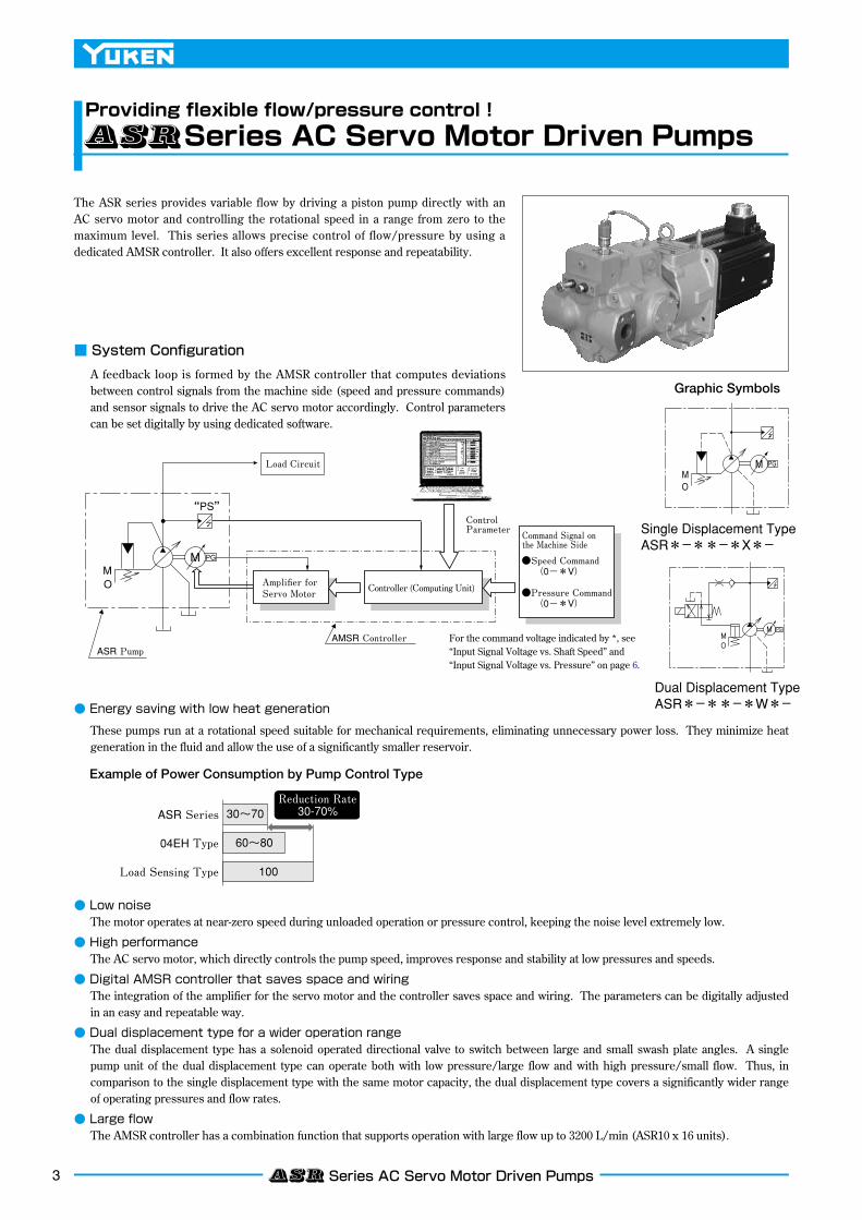
Providing flexible flow/pressure control !ASRSeries AC Servo Motor Driven Pumps
■ System Configuration
A feedback loop is formed by the AMSR controller that computes deviations between control signals from the machine side (speed and pressure commands) and sensor signals to drive the AC servo motor accordingly. Control parameters can be set digitally by using dedicated software.
● Energy saving with low heat generation
These pumps run at a rotational speed suitable for mechanical requirements, eliminating unnecessary power loss. They minimize heat generation in the fluid and allow the use of a significantly smaller reservoir.
● Low noiseThe motor operates at near-zero speed during unloaded operation or pressure control, keeping the noise level extremely low.
● High performanceThe AC servo motor, which directly controls the pump speed, improves response and stability at low pressures and speeds.
● Digital AMSR controller that saves space and wiringThe integration of the amplifier for the servo motor and the controller saves space and wiring. The parameters can be digitally adjusted in an easy and repeatable way.
● Dual displacement type for a wider operation rangeThe dual displacement type has a solenoid operated directional valve to switch between large and small swash plate angles. A single pump unit of the dual displacement type can operate both with low pressure/large flow and with high pressure/small flow. Thus, in comparison to the single displacement type with the same motor capacity, the dual displacement type covers a significantly wider range of operating pressures and flow rates.
● Large flowThe AMSR controller has a combination function that supports operation with large flow up to 3200 L/min (ASR10 x 16 units).
Graphic Symbols
Single Displacement TypeASR*−**−*X*−
Dual Displacement TypeASR*−**−*W*−
Example of Power Consumption by Pump Control Type
30~70Reduction Rate30-70%
60~80
100
ASR Series
04EH Type
Load Sensing Type
The ASR series provides variable flow by driving a piston pump directly with an AC servo motor and controlling the rotational speed in a range from zero to the maximum level. This series allows precise control of flow/pressure by using a dedicated AMSR controller. It also offers excellent response and repeatability.
MO
M PG
MO
M PG
4ASR Series AC Servo Motor Driven Pumps
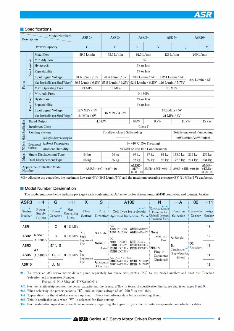
■ Specifications
■ Model Number Designation
The model numbers below indicate packages each containing an AC servo motor driven pump, AMSR controller, and dynamic brakes.
★By adjusting the controller, the maximum flow rate/5 V (39.5 L/min/5 V) and the maximum operating pressure/5 V (21 MPa/5 V) can be set.
★1. To order an AC servo motor driven pump separately for spare use, prefix “N-” to the model number and omit the Function Selection and Parameter Number.
Example)N-ASR3-4G-HXSA100N-11★2. For the relationship between the power capacity and the pressure/flow in terms of specification limits, see charts on pages 8 and 9.★3. When selecting the power capacity “E”, only an input voltage of AC 200 V is available.★4. Types shown in the shaded areas are optional. Check the delivery date before selecting them.★5. This is applicable only when “W” is selected for flow setting.★6. For combination operation, consult us separately regarding the types of hydraulic circuits, components, and electric cables.
ASR3 -4
ASR1
ASR2
ASR3
ASR5
ASR10
C
C
E★3、G
G、J
J、M
H:21 MPa
C:16 MPa
H:21 MPa
SeriesNumber
PowerSupplyVoltage
None :AC 200 V
4:AC 400 V
X
FlowSetting
X:SingleDisplacementType
W:DualDisplacementType
S A100
PortDirection
11
12
11
11
12
-11
DesignNumber
00
ParameterNumber
S:Side
None: Axial
None: Terminal Box
N:DIN Plug-in Connector (Optional)
ACA100 :AC100V A120 :AC120VA200 :AC200V A240 :AC240V
DCNone:DC24V D12 :DC12V D48 :DC48V D100 :DC100V D110 :DC110V D200 :DC200V D220 :DC220V
AC (AC <-> DC)R100 :AC100V R110 :AC110VR200 :AC200V R220 :AC220V
00: Standard
-A
FunctionSelection
NElectrical ConduitConnection forSolenoid OperatedDirectional Valve
A: Single
B: Combination★6
(Single Operation Allowed)
A:HorizontalB:Vertical
G
PowerCapacity
-HMax.
OperatingPres.
Coil Type for SolenoidOperated Directional Valve
★2 ★4 ★5★4 ★5
★1
Model NumbersDescription ASR 1− ASR 2− ASR 3− ASR 5− ASR10−
Power Capacity C C E G J M
Pum
p
Flow
Con
trol
Max. Flow 39.5 L/min 55.5 L/min 92.3 L/min 129 L/min 200 L/min
Min.Adj.Flow 1%
Hysteresis 1% or less
Repeatability 1% or less
Input Signal Voltage 31.6 L/min / 5V 44.4 L/min / 5V 73.8 L/min / 5V 112.4 L/min / 5V200 L/min / 5V
Max. Permissible Input Signal Voltage★ 39.5 L/min / 6.25V 55.5 L/min / 6.25V 92.3 L/min / 6.25V 129 L/min / 5.75V
Pres
. Con
trol
Max. Operating Pres. 21 MPa 16 MPa 21 MPa
Min. Adj. Pres. 0.1 MPa
Hysteresis 1% or less
Repeatability 1% or less
Input Signal Voltage 17.5 MPa / 5V16 MPa / 4.57V
17.5 MPa / 5V
Max. Permissible Input Signal Voltage★ 21 MPa / 6V 21 MPa / 6V
AC Se
rvo M
otor S
pecifi
catio
ns Rated Output 4.5 kW 6 kW 8 kW 11 kW 15 kW
Insulation Class Class F
Cooling System Totally-enclosed Self-cooling Totally-enclosed Fan-cooling
Cooling Fan Power Consumption ──── 62W(50Hz)/76W(60Hz)
Environmental Condition
Ambient Temperature 0 - +40 ℃ (No Freezing)
Ambient Humidity 80 %RH or less (No Condensation)
Mas
s Single Displacement Type 54 kg 54 kg 80 kg 87 kg 94 kg 175.5 kg 213 kg 233 kg
Dual Displacement Type 55 kg 55 kg 82 kg 89 kg 96 kg 177.5 kg 214 kg 234 kg
Applicable Controller Model Number AMSR−*C−*00−10
AMSR−2DE−
*00−10AMSR−*FGI−*00−10 AMSR−*HJL−*00−10
AMSR−*KMO−*00−10
5 ASR Series AC Servo Motor Driven Pumps
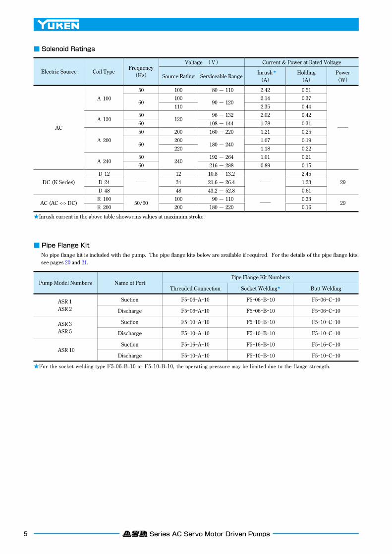
■ Pipe Flange Kit
No pipe flange kit is included with the pump. The pipe flange kits below are available if required. For the details of the pipe flange kits, see pages 20 and 21.
■ Solenoid Ratings
★ For the socket welding type F5-06-B-10 or F5-10-B-10, the operating pressure may be limited due to the flange strength.
★ Inrush current in the above table shows rms values at maximum stroke.
Pump Model Numbers Name of PortPipe Flange Kit Numbers
Threaded Connection Socket Welding★ Butt Welding
ASR 1ASR 2
ASR 3ASR 5
ASR 10
Suction
Discharge
Suction
Discharge
Suction
Discharge
F5−06−A−10
F5−06−A−10
F5−10−A−10
F5−10−A−10
F5−16−A−10
F5−10−A−10
F5−06−B−10
F5−06−B−10
F5−10−B−10
F5−10−B−10
F5−16−B−10
F5−10−B−10
F5−06−C−10
F5−06−C−10
F5−10−C−10
F5−10−C−10
F5−16−C−10
F5−10−C−10
Electric Source Coil TypeFrequency
(Hz)
Voltage (V) Current & Power at Rated Voltage
Source Rating Serviceable Range Inrush ★
(A)Holding(A)
Power(W)
AC
A 10050 100 80 — 110 2.42 0.51
──
60100
90 — 1202.14 0.37
110 2.35 0.44
A 12050
120 96 — 132 2.02 0.42
60 108 — 144 1.78 0.31
A 20050 200 160 — 220 1.21 0.25
60200
180 — 2401.07 0.19
220 1.18 0.22
A 24050
240192 — 264 1.01 0.21
60 216 — 288 0.89 0.15
DC (K Series)D 12
──12 10.8 — 13.2
──2.45
29D 24 24 21.6 — 26.4 1.23D 48 48 43.2 — 52.8 0.61
AC (AC <-> DC)R 100
50/60100 90 — 110
──0.33
29R 200 200 180 — 220 0.16
6ASR Series AC Servo Motor Driven Pumps
L
7
Safety Valve Pressure Adj. Screw
L
7
Flow Adj. Screw10
60
50
40
30
20
10
020 30
ASR2
ASR1
1 2 3 4 5Input Voltage V
6
24
20
16
12
8
4
0
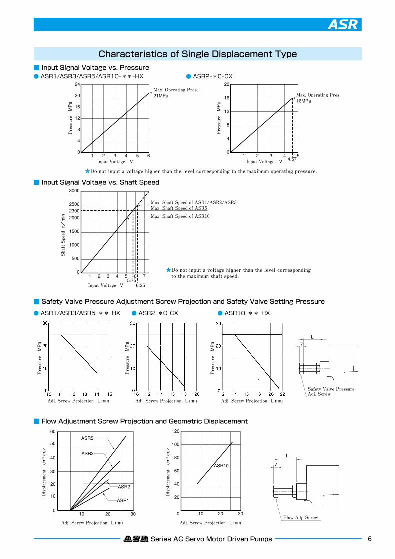
Max. Operating Pres.21MPa
Pressure MPa
Pressure MPa
Shaft Speed r/min
1 2 3 4 54.57Input Voltage V
20
16
12
8
4
0
Max. Operating Pres.16MPa
1 2 3 4 5 6 7
6.255.75
Input Voltage V
3000
2500
2000
1500
1000
500
0
2300
ASR10
ASR3
ASR5
Max. Shaft Speed of ASR1/ASR2/ASR3Max. Shaft Speed of ASR5
Max. Shaft Speed of ASR10
10 200 30
120
100
80
60
40
20
Pressure MPa
Displacement cm
3 /rev
Displacement cm
3 /rev
Pressure MPa
Pressure MPa
Adj. Screw Projection L mm
Adj. Screw Projection L mm Adj. Screw Projection L mm
Adj. Screw Projection L mm Adj. Screw Projection L mm
Characteristics of Single Displacement Type■ Input Signal Voltage vs. Pressure● ASR1/ASR3/ASR5/ASR10-**-HX
■ Input Signal Voltage vs. Shaft Speed
● ASR2-*C-CX
● ASR1/ASR3/ASR5-**-HX
■ Safety Valve Pressure Adjustment Screw Projection and Safety Valve Setting Pressure
● ASR10-**-HX
■ Flow Adjustment Screw Projection and Geometric Displacement
● ASR2-*C-CX
★Do not input a voltage higher than the level corresponding to the maximum operating pressure.
★Do not input a voltage higher than the level corresponding to the maximum shaft speed.
7 ASR Series AC Servo Motor Driven Pumps
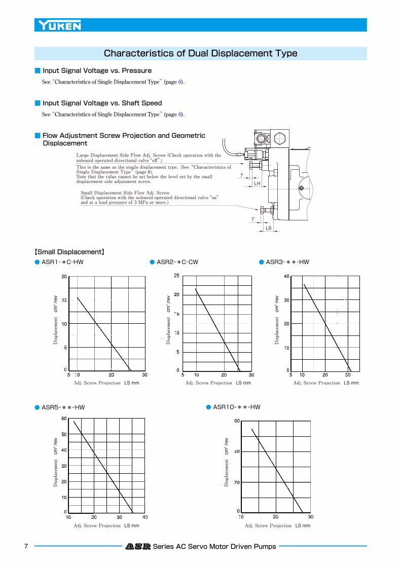
Large Displacement Side Flow Adj. Screw (Check operation with the solenoid operated directional valve“off”.)This is the same as the single displacement type. See“Characteristics of Single Displacement Type”(page 6).Note that the value cannot be set below the level set by the small displacement side adjustment screw.
Small Displacement Side Flow Adj. Screw(Check operation with the solenoid operated directional valve“on”and at a load pressure of 3 MPa or more.)
7
7
LS
LH
Displacement cm
3 /rev
Displacement cm
3 /rev
Displacement cm
3 /rev
Displacement cm
3 /rev
Displacement cm
3 /rev
Adj. Screw Projection LS mm
Adj. Screw Projection LS mm Adj. Screw Projection LS mm
Adj. Screw Projection LS mm Adj. Screw Projection LS mm
■ Input Signal Voltage vs. Pressure
See “Characteristics of Single Displacement Type” (page 6).
■ Input Signal Voltage vs. Shaft Speed
See “Characteristics of Single Displacement Type” (page 6).
■ Flow Adjustment Screw Projection and Geometric Displacement
● ASR5−**−HW
● ASR1−*C−HW ● ASR2−*C−CW ● ASR3−**−HW
【Small Displacement】
● ASR10−**−HW
Characteristics of Dual Displacement Type
8ASR Series AC Servo Motor Driven Pumps
60
40
20
100
80
60
40
20
Pressure MPa Pressure MPa
Pressure MPa Pressure MPa
Pressure MPa Pressure MPa
Pressure MPa Pressure MPa
150
120
90
60
30
5 10 15 20 250
5 10 15 20 25
5 10 15 20 25
0
0
250
200
150
100
50
5 10 15 20 250
150
120
90
60
30
5 10 15 20 250
100
80
60
40
20
5 10 15 20 250
60
40
20
5 10 15 20 250
250
200
150
100
50
5 10 15 20 250
1
1
2
2
3
3
1
2
3
1
2
3
1
2
3
1
2
3
1
2
3
Flow Rate
Flow Rate L/min
Flow Rate L/min
Flow Rate L/min
Flow Rate L/min
Flow Rate L/min
Flow Rate L/min
Flow Rate L/min
Flow Rate L/min
Pressure
2
1
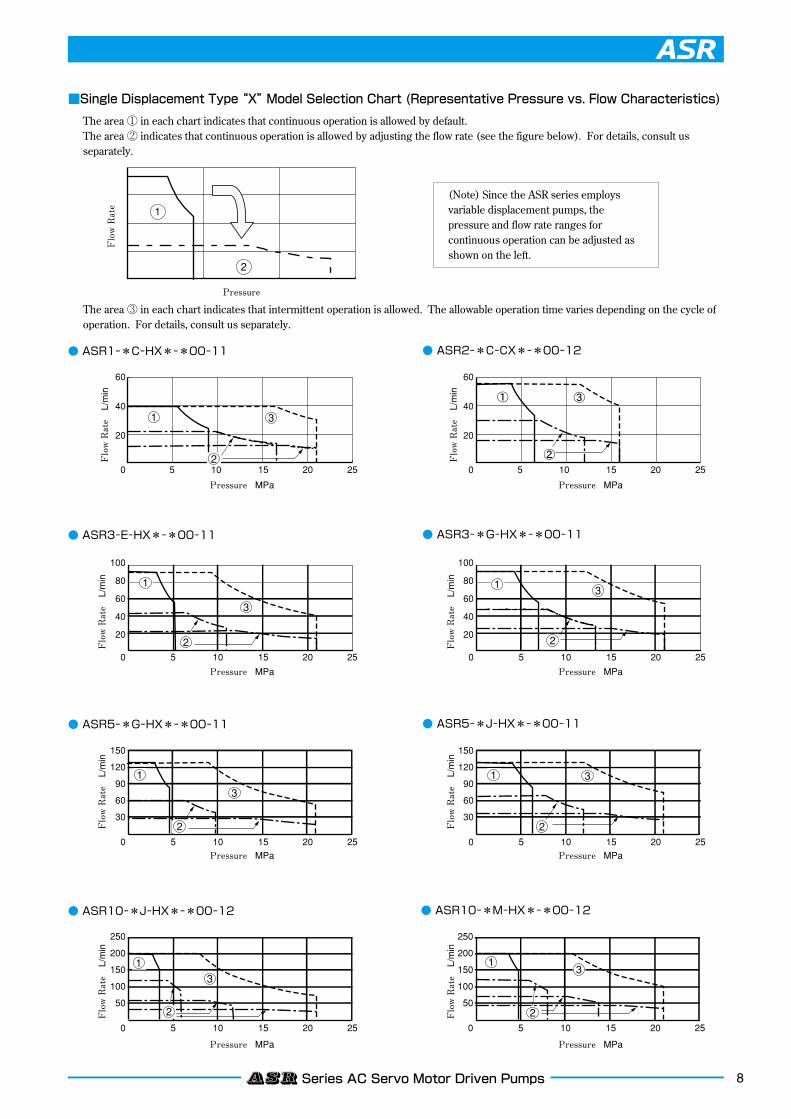
■Single Displacement Type “X” Model Selection Chart (Representative Pressure vs. Flow Characteristics)
The area ① in each chart indicates that continuous operation is allowed by default.The area ② indicates that continuous operation is allowed by adjusting the flow rate (see the figure below). For details, consult us separately.
The area ③ in each chart indicates that intermittent operation is allowed. The allowable operation time varies depending on the cycle of operation. For details, consult us separately.
● ASR1−*C−HX*−*00−11 ● ASR2−*C−CX*−*00−12
● ASR3−E−HX*−*00−11 ● ASR3−*G−HX*−*00−11
● ASR5−*G−HX*−*00−11 ● ASR5−*J−HX*−*00−11
● ASR10−*J−HX*−*00−12 ● ASR10−*M−HX*−*00−12
(Note) Since the ASR series employs variable displacement pumps, the pressure and flow rate ranges for continuous operation can be adjusted as shown on the left.
9 ASR Series AC Servo Motor Driven Pumps
60
40
20
100
80
60
40
20
150
120
90
60
30
5 10 15 20 250
5 10 15 20 25
5 10 15 20 25
0
0
250
200
150
100
50
5 10 15 20 250
150
120
90
60
30
5 10 15 20 250
100
80
60
40
20
5 10 15 20 250
60
40
20
5 10 15 20 250
250
200
150
100
50
5 10 15 20 250
1
1
1
1 1
1
1
2
2
2
2
2
2
2
3
3
3
3
3
3
3
3
2
Pressure MPa
Flow Rate
Flow Rate L/min
Pressure MPa
Flow Rate L/min
Pressure MPa
Flow Rate L/min
Pressure MPa
Pressure MPa
Flow Rate L/min
Pressure MPa
Flow Rate L/min
Flow Rate L/min
Pressure MPa
Flow Rate L/min
Pressure MPa
Flow Rate L/min
Pressure
2
1
2
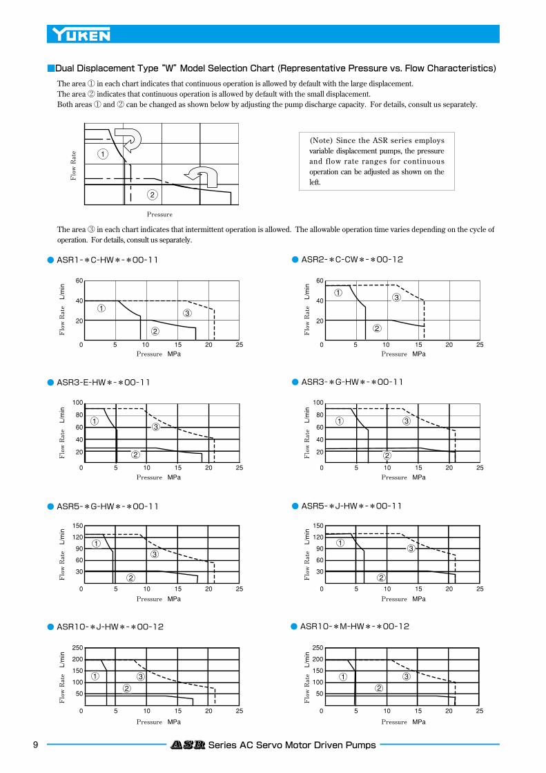
■Dual Displacement Type “W” Model Selection Chart (Representative Pressure vs. Flow Characteristics)
The area ① in each chart indicates that continuous operation is allowed by default with the large displacement.The area ② indicates that continuous operation is allowed by default with the small displacement.Both areas ① and ② can be changed as shown below by adjusting the pump discharge capacity. For details, consult us separately.
The area ③ in each chart indicates that intermittent operation is allowed. The allowable operation time varies depending on the cycle of operation. For details, consult us separately.
● ASR1−*C−HW*−*00−11 ● ASR2−*C−CW*−*00−12
● ASR3−E−HW*−*00−11 ● ASR3−*G−HW*−*00−11
● ASR5−*G−HW*−*00−11 ● ASR5−*J−HW*−*00−11
● ASR10−*J−HW*−*00−12 ● ASR10−*M−HW*−*00−12
(Note) Since the ASR series employs variable displacement pumps, the pressure and flow rate ranges for continuous operation can be adjusted as shown on the left.
10ASR Series AC Servo Motor Driven Pumps
188
113
13
7676
(56)
183.5
59.5
304
284.5
238.8
81.1
88140.9
47.6
78170
22.2 16
20114
6028
14
96
188
32.5 32.5
47.6
47.6
22.2 22.2
(56)
304
Wiring Space
WiringSpace
Fully Extended 252
113
170
205
Wiring Space
87
24
188
188
113
150.5
113
150.5
(59) 266 304
266
205
304
Suction/Discharge Port Position Solenoid Operated Directional Valve of Terminal Box Type
Solenoid Operated Directional Valve of Terminal Box Type
Solenoid Operated Directional Valve of Plug-in Connector Type
Solenoid Operated Directional Valve of Plug-in Connector Type
★Lock NutTorque 10.3 - 11.3 N·m
Cable DepartureCable Applicable:Outside Dia. 8 - 10 mm
The position can be changed by loosening the lock nut ★. Be sure to tighten the lock nut after changing the position.
AC Type: 192.5
DC Type: 203.5
R Type: 206.5
★Lock NutTorque 10.3 - 11.3 N·m
Cable DepartureCable Applicable:Outside Dia. 8 - 10 mm
The position can be changed by loosening the lock nut★. Be sure to tighten the lock nut after changing the position.
AC Type: 192.5
DC Type: 203.5
R Type: 206.5
Drain Port“DR” Rc 3/8
Discharge Port 19 Dia.Suction Port 19 Dia. (Opposite Side)
M10 Thd. 17 Deep 2 × 4 Places
Flow Adj. Screw17 Hex.
Safety Valve Pressure Adj. Screw 17 Hex.
Pressure SensorMotor Cable Connector
Encoder Cable Connector
Filling PortPlug 22 Hex.
Fully Extended 252Discharge Port PositionSuction Port Position
Discharge Port19 Dia.
M10 Thd. 17 Deep 8 Places
Suction Port 19 Dia.
Suction/Discharge Port Position
Pressure SensorElectrical Conduit Connection 2-G 1/2
Large Displacement Side Flow Adj. Screw17 Hex.
Small Displacement Side Flow Adj. Screw17 Hex.
7474172.5
DEC.
DEC.
INC.
INC.
188
113
13
7676
(56)
183.5
59.5
304
284.5
238.8
81.1
88140.9
47.6
78170
22.2 16
20114
6028
14
96
188
32.5 32.5
47.6
47.6
22.2 22.2
(56)
304
Wiring Space
WiringSpace
Fully Extended 252
113
170
205
Wiring Space
87
24
188
188
113
150.5
113
150.5
(59) 266 304
266
205
304
Suction/Discharge Port Position Solenoid Operated Directional Valve of Terminal Box Type
Solenoid Operated Directional Valve of Terminal Box Type
Solenoid Operated Directional Valve of Plug-in Connector Type
Solenoid Operated Directional Valve of Plug-in Connector Type
★Lock NutTorque 10.3 - 11.3 N·m
Cable DepartureCable Applicable:Outside Dia. 8 - 10 mm
The position can be changed by loosening the lock nut ★. Be sure to tighten the lock nut after changing the position.
AC Type: 192.5
DC Type: 203.5
R Type: 206.5
★Lock NutTorque 10.3 - 11.3 N·m
Cable DepartureCable Applicable:Outside Dia. 8 - 10 mm
The position can be changed by loosening the lock nut★. Be sure to tighten the lock nut after changing the position.
AC Type: 192.5
DC Type: 203.5
R Type: 206.5
Drain Port“DR” Rc 3/8
Discharge Port 19 Dia.Suction Port 19 Dia. (Opposite Side)
M10 Thd. 17 Deep 2 × 4 Places
Flow Adj. Screw17 Hex.
Safety Valve Pressure Adj. Screw 17 Hex.
Pressure SensorMotor Cable Connector
Encoder Cable Connector
Filling PortPlug 22 Hex.
Fully Extended 252Discharge Port PositionSuction Port Position
Discharge Port19 Dia.
M10 Thd. 17 Deep 8 Places
Suction Port 19 Dia.
Suction/Discharge Port Position
Pressure SensorElectrical Conduit Connection 2-G 1/2
Large Displacement Side Flow Adj. Screw17 Hex.
Small Displacement Side Flow Adj. Screw17 Hex.
7474172.5
DEC.
DEC.
INC.
INC.
Single Displacement Type
Dual Displacement Type
188
113
13
7676
(56)
183.5
59.5
304
284.5
238.8
81.1
88140.9
47.6
78170
22.2 16
20114
6028
14
96
188
32.5 32.5
47.6
47.6
22.2 22.2
(56)
304
Wiring Space
WiringSpace
Fully Extended 252113
170
205
Wiring Space
87
24
188
188
113
150.5
113
150.5
(59) 266 304
266
205
304
Suction/Discharge Port Position Solenoid Operated Directional Valve of Terminal Box Type
Solenoid Operated Directional Valve of Terminal Box Type
Solenoid Operated Directional Valve of Plug-in Connector Type
Solenoid Operated Directional Valve of Plug-in Connector Type
★Lock NutTorque 10.3 - 11.3 N·m
Cable DepartureCable Applicable:Outside Dia. 8 - 10 mm
The position can be changed by loosening the lock nut ★. Be sure to tighten the lock nut after changing the position.
AC Type: 192.5
DC Type: 203.5
R Type: 206.5
★Lock NutTorque 10.3 - 11.3 N·m
Cable DepartureCable Applicable:Outside Dia. 8 - 10 mm
The position can be changed by loosening the lock nut★. Be sure to tighten the lock nut after changing the position.
AC Type: 192.5
DC Type: 203.5
R Type: 206.5
Drain Port“DR” Rc 3/8
Discharge Port 19 Dia.Suction Port 19 Dia. (Opposite Side)
M10 Thd. 17 Deep 2 × 4 Places
Flow Adj. Screw17 Hex.
Safety Valve Pressure Adj. Screw 17 Hex.
Pressure SensorMotor Cable Connector
Encoder Cable Connector
Filling PortPlug 22 Hex.
Fully Extended 252Discharge Port PositionSuction Port Position
Discharge Port19 Dia.
M10 Thd. 17 Deep 8 Places
Suction Port 19 Dia.
Suction/Discharge Port Position
Pressure SensorElectrical Conduit Connection 2-G 1/2
Large Displacement Side Flow Adj. Screw17 Hex.
Small Displacement Side Flow Adj. Screw17 Hex.
7474172.5
DEC.
DEC.
INC.
INC.
188
113
13
7676
(56)
183.5
59.5
304
284.5
238.8
81.1
88140.9
47.6
78170
22.2 16
20114
6028
14
96
188
32.5 32.5
47.6
47.6
22.2 22.2
(56)
304
Wiring Space
WiringSpace
Fully Extended 252
113
170
205
Wiring Space
87
24
188
188
113
150.5
113
150.5
(59) 266 304
266
205
304
Suction/Discharge Port Position Solenoid Operated Directional Valve of Terminal Box Type
Solenoid Operated Directional Valve of Terminal Box Type
Solenoid Operated Directional Valve of Plug-in Connector Type
Solenoid Operated Directional Valve of Plug-in Connector Type
★Lock NutTorque 10.3 - 11.3 N·m
Cable DepartureCable Applicable:Outside Dia. 8 - 10 mm
The position can be changed by loosening the lock nut ★. Be sure to tighten the lock nut after changing the position.
AC Type: 192.5
DC Type: 203.5
R Type: 206.5
★Lock NutTorque 10.3 - 11.3 N·m
Cable DepartureCable Applicable:Outside Dia. 8 - 10 mm
The position can be changed by loosening the lock nut★. Be sure to tighten the lock nut after changing the position.
AC Type: 192.5
DC Type: 203.5
R Type: 206.5
Drain Port“DR” Rc 3/8
Discharge Port 19 Dia.Suction Port 19 Dia. (Opposite Side)
M10 Thd. 17 Deep 2 × 4 Places
Flow Adj. Screw17 Hex.
Safety Valve Pressure Adj. Screw 17 Hex.
Pressure SensorMotor Cable Connector
Encoder Cable Connector
Filling PortPlug 22 Hex.
Fully Extended 252Discharge Port PositionSuction Port Position
Discharge Port19 Dia.
M10 Thd. 17 Deep 8 Places
Suction Port 19 Dia.
Suction/Discharge Port Position
Pressure SensorElectrical Conduit Connection 2-G 1/2
Large Displacement Side Flow Adj. Screw17 Hex.
Small Displacement Side Flow Adj. Screw17 Hex.
7474172.5
DEC.
DEC.
INC.
INC.
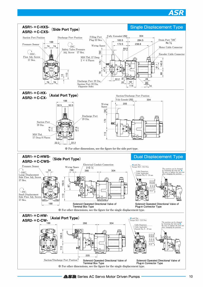
ASR1-*C-HXS-(Side Port Type)
ASR2-*C-CXS-
● For other dimensions, see the figure for the single displacement type.
● For other dimensions, see the figure for the single displacement type.
● For other dimensions, see the figure for the side port type.
ASR1-*C-HWS-(Side Port Type)
ASR2-*C-CWS-
ASR1-*C-HW-(Axial Port Type)
ASR2-*C-CW-
ASR1-*C-HX-(Axial Port Type)
ASR2-*C-CX-
202
38
113
228
154.5
289
Suction/Discharge Port Position
AC Type: 196.5
DC Type: 207.5
R Type: 210.5
Solenoid Operated Directional Valve of Terminal Box Type
Solenoid Operated Directional Valve of Plug-in Connector Type
★Lock NutTorque 10.3 - 11.3 N·m
Cable DepartureCable Applicable:Outside Dia. 8 - 10 mm
The position can be changed by loosening the lock nut★. Be sure to tighten the lock nut after changing the position.
Wiring Space
91
30
202
113
154.5
(56) 289
Electrical Conduit Connection2-G 1/2
Pressure Sensor
Large Displacement Side Flow Adj. Screw17 Hex.
Small Displacement Side Flow Adj. Screw17 Hex.
DEC.
INC. AC Type: 196.5
DC Type: 207.5
R Type: 210.5
Solenoid Operated Directional Valve of Terminal Box Type
Solenoid Operated Directional Valve of Plug-in Connector Type
★Lock NutTorque 10.3 - 11.3 N·m
Cable DepartureCable Applicable:Outside Dia. 8 - 10 mm
The position can be changed by loosening the lock nut★. Be sure to tighten the lock nut after changing the position.
20236 36
Fully Extended 280172
113
228
Discharge Port30 Dia.
Suction/Discharge Port Position
M10 Thd. 19 Deep 8 Places
30.2 30.2
58.7
58.7
Suction Port35 Dia.
90
58.7
30.220 60
114 14
287676
211.5
81.1
88D
188
113
13
202
16
A
B
C
M10 Thd. 19 Deep 2 × 4 Places
WiringSpace
86 86
Discharge Port 32 Dia.Suction Port 35 Dia. (Opposite Side)
Motor Cable Connector
Encoder Cable Connector
Fully Extended 280Filling PortPlug 22 Hex.
Drain Port“DR” Rc 1/2
Flow Adj. Screw17 Hex.
Pressure Sensor
Suction Port PositionDischarge Port Position
Safety Valve Pressure Adj. Screw 17 Hex.
196.5
(56)
63
105
DEC.
INC.
172
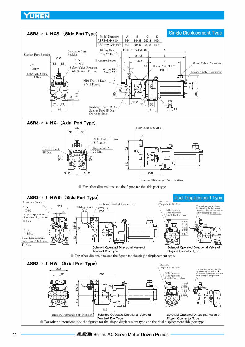
ASR3-E-H*S-ASR3-*G-H*S-
364Model Numbers
344.5 290.8404 384.5 330.8
A B C149.1149.1
D
11 ASR Series AC Servo Motor Driven Pumps
Single Displacement Type
Dual Displacement Type
ASR3-**-HXS-(Side Port Type)
● For other dimensions, see the figures for the single displacement type and the dual displacement side port type.
● For other dimensions, see the figure for the single displacement type.
● For other dimensions, see the figure for the side port type.
ASR3-**-HWS-(Side Port Type)
ASR3-**-HW-(Axial Port Type)
ASR3-**-HX-(Axial Port Type)
20 60
11414
28
88149.1
7676
188
232
100 100
16
23220
197
113
240.5
13 113
98
30.2
81.1
224
209
83.5
90
WiringSpace
179.5
113
110
232
232301.5
179.5
113
240.5
37
28 (59) 301.5
WiringSpace
Discharge Port PositionSuction Port Position
20
4149
Solenoid Operated Directional Valve of Terminal Box Type
Solenoid Operated Directional Valve of Plug-in Connector Type
Solenoid Operated Directional Valve of Terminal Box Type
Solenoid Operated Directional Valve of Plug-in Connector Type
★Lock NutTorque 10.3 - 11.3 N·m
Cable DepartureCable Applicable:Outside Dia. 8 - 10 mm
The position can be changed by loosening the lock nut★. Be sure to tighten the lock nut after changing the position.
AC Type: 221.5
DC Type: 232.5
R Type: 235.5
AC Type: MAX. 221.5
DC Type: MAX. 232.5
R Type: MAX. 235.5
Cable DepartureCable Applicable:Outside Dia. 8 - 10 mm
The position can be changed by loosening the lock nut★. Be sure to tighten the lock nut after changing the position.
★Lock NutTorque 10.3 - 11.3 N·m
Encoder Cable Connector
Motor Cable Connector
Discharge Port 30 Dia.
Suction Port 35 Dia. (Opposite Side)
Electrical Conduit Connection
2-G 1/2
Flow Adj. Screw17 Hex.
Safety Valve PressureAdj. Screw 17 Hex.
30.2 30.2
38 38
58.7
58.7
Suction Port 35 Dia.
M10 Thd. 19 Deep 8 Places
M10 Thd. 19 Deep 4 Places
Drain Port“DR”★2-Rc 3/4 (Both Sides)
★Use either of two drain ports at your option. Keep the unused port plugged.
404
384.5
330.8
Fully Extended 292.5
Fully Extended 292.5
Filling PortPlug 22 Hex.
Discharge Port 32 Dia.
Suction/Discharge Port Position
Pressure Sensor
Pressure Sensor
Suction/Discharge Port Position
(56)
PressureSensor
Large Displacement Side Flow Adj. Screw17 Hex.
DEC.
Small Displacement Side Flow Adj. Screw17 Hex.
INC.
DEC.
INC.
58.7
197
12ASR Series AC Servo Motor Driven Pumps
Single Displacement Type
20 60
11414
28
88149.1
7676
188
232
100 100
16
23220
197
113
240.5
13 113
98
30.2
81.1
224
209
83.5
90
WiringSpace
179.5
113
110
232
232301.5
179.5
113
240.5
37
28 (59) 301.5
WiringSpace
Discharge Port PositionSuction Port Position
20
4149
Solenoid Operated Directional Valve of Terminal Box Type
Solenoid Operated Directional Valve of Plug-in Connector Type
Solenoid Operated Directional Valve of Terminal Box Type
Solenoid Operated Directional Valve of Plug-in Connector Type
★Lock NutTorque 10.3 - 11.3 N·m
Cable DepartureCable Applicable:Outside Dia. 8 - 10 mm
The position can be changed by loosening the lock nut★. Be sure to tighten the lock nut after changing the position.
AC Type: 221.5
DC Type: 232.5
R Type: 235.5
AC Type: MAX. 221.5
DC Type: MAX. 232.5
R Type: MAX. 235.5
Cable DepartureCable Applicable:Outside Dia. 8 - 10 mm
The position can be changed by loosening the lock nut★. Be sure to tighten the lock nut after changing the position.
★Lock NutTorque 10.3 - 11.3 N·m
Encoder Cable Connector
Motor Cable Connector
Discharge Port 30 Dia.
Suction Port 35 Dia. (Opposite Side)
Electrical Conduit Connection
2-G 1/2
Flow Adj. Screw17 Hex.
Safety Valve PressureAdj. Screw 17 Hex.
30.2 30.2
38 38
58.7
58.7
Suction Port 35 Dia.
M10 Thd. 19 Deep 8 Places
M10 Thd. 19 Deep 4 Places
Drain Port“DR”★2-Rc 3/4 (Both Sides)
★Use either of two drain ports at your option. Keep the unused port plugged.
404
384.5
330.8
Fully Extended 292.5
Fully Extended 292.5
Filling PortPlug 22 Hex.
Discharge Port 32 Dia.
Suction/Discharge Port Position
Pressure Sensor
Pressure Sensor
Suction/Discharge Port Position
(56)
PressureSensor
Large Displacement Side Flow Adj. Screw17 Hex.
DEC.
Small Displacement Side Flow Adj. Screw17 Hex.
INC.
DEC.
INC.
58.7
197
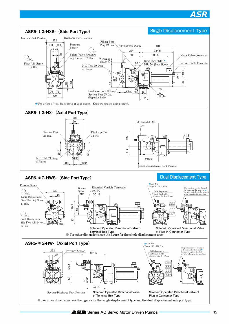
ASR5-*G-HXS-(Side Port Type)
● For other dimensions, see the figures for the single displacement type and the dual displacement side port type.
● For other dimensions, see the figure for the single displacement type.
ASR5-*G-HWS-(Side Port Type)
ASR5-*G-HW-(Axial Port Type)
ASR5-*G-HX-(Axial Port Type)
Dual Displacement Type
13 ASR Series AC Servo Motor Driven Pumps
140
324
29
140
395
190
260
41
20
49
100 100
260
20
260
324
395
37
190
250.5
179.5
311.5
Wiring Space
Fully Extended 302.5
Fully Extended 302.5
234
640
145 205
126
59421993.5
43
30 22174
90
34 106
197
225
640
190
250.5M10 Thd. 19 Deep 8 Places
Wiring Space
Wiring Space(59) 311.5 640
AC Type: 221.5
DC Type: 232.5
R Type: 235.5
★Lock NutTorque 10.3 - 11.3 N·m
Cable DepartureCable Applicable:Outside Dia. 8 - 10 mm
The position can be changed by loosening the lock nut★. Be sure to tighten the lock nut after changing the position.
AC Type: MAX. 221.5
DC Type: MAX. 232.5
R Type: MAX. 235.5
★Lock NutTorque 10.3 - 11.3 N·m
Cable DepartureCable Applicable:Outside Dia. 8 - 10 mm
The position can be changed by loosening the lock nut★. Be sure to tighten the lock nut after changing the position.
Solenoid Operated Directional Valve of Terminal Box Type
Solenoid Operated Directional Valve of Plug-in Connector Type
Solenoid Operated Directional Valve of Terminal Box Type
Solenoid Operated Directional Valve of Plug-in Connector Type
190
110
179.5
Pressure SensorElectrical Conduit Connection2-G 1/2
Large Displacement Side Flow Adj. Screw17 Hex.
Small Displacement Side Flow Adj. Screw17 Hex.
M10 Thd. 19 Deep 2 × 4 Places
Suction/Discharge Port Position
Suction/Discharge Port Position
Motor Cable/Fan Wiring PortEncoder Cable Connector (Opposite Side)
Pressure Sensor
Pressure Sensor
Wall Clearance of 100 or more
Discharge Port PositionSuction Port Position
Drain Port Position
Intake
Exhaust
Filling PortPlug 22 Hex.
Drain Port“DR”★2-Rc 3/4 (Both Sides)
Discharge Port 30 Dia.Suction Port 35 Dia. (Opposite Side)
30.2
3838
30.2
324
324
26028
395
58.7
395
58.7
Suction Port 35 Dia.
Discharge Port 32 Dia.
(56)
197
98
58.7
30.2
(56)
DEC.
INC.
Flow Adj. Screw17 Hex.
DEC.
Safety Valve Pressure Adj. Screw17 Hex.
INC.
★Use either of two drain ports at your option. Keep the unused port plugged.
140
324
29
140
395
190
260
41
20
49
100 100
260
20
260
324
395
37
190
250.5
179.5
311.5
Wiring Space
Fully Extended 302.5
Fully Extended 302.5
234
640
145 205
126
59421993.5
43
30 22174
90
34 106
197
225
640190
250.5M10 Thd. 19 Deep 8 Places
Wiring Space
Wiring Space(59) 311.5 640
AC Type: 221.5
DC Type: 232.5
R Type: 235.5
★Lock NutTorque 10.3 - 11.3 N·m
Cable DepartureCable Applicable:Outside Dia. 8 - 10 mm
The position can be changed by loosening the lock nut★. Be sure to tighten the lock nut after changing the position.
AC Type: MAX. 221.5
DC Type: MAX. 232.5
R Type: MAX. 235.5
★Lock NutTorque 10.3 - 11.3 N·m
Cable DepartureCable Applicable:Outside Dia. 8 - 10 mm
The position can be changed by loosening the lock nut★. Be sure to tighten the lock nut after changing the position.
Solenoid Operated Directional Valve of Terminal Box Type
Solenoid Operated Directional Valve of Plug-in Connector Type
Solenoid Operated Directional Valve of Terminal Box Type
Solenoid Operated Directional Valve of Plug-in Connector Type
190
110
179.5
Pressure SensorElectrical Conduit Connection2-G 1/2
Large Displacement Side Flow Adj. Screw17 Hex.
Small Displacement Side Flow Adj. Screw17 Hex.
M10 Thd. 19 Deep 2 × 4 Places
Suction/Discharge Port Position
Suction/Discharge Port Position
Motor Cable/Fan Wiring PortEncoder Cable Connector (Opposite Side)
Pressure Sensor
Pressure Sensor
Wall Clearance of 100 or more
Discharge Port PositionSuction Port Position
Drain Port Position
Intake
Exhaust
Filling PortPlug 22 Hex.
Drain Port“DR”★2-Rc 3/4 (Both Sides)
Discharge Port 30 Dia.Suction Port 35 Dia. (Opposite Side)
30.2
3838
30.2
324
324
26028
395
58.7
395
58.7
Suction Port 35 Dia.
Discharge Port 32 Dia.
(56)
197
98
58.7
30.2
(56)
DEC.
INC.
Flow Adj. Screw17 Hex.
DEC.
Safety Valve Pressure Adj. Screw17 Hex.
INC.
★Use either of two drain ports at your option. Keep the unused port plugged.
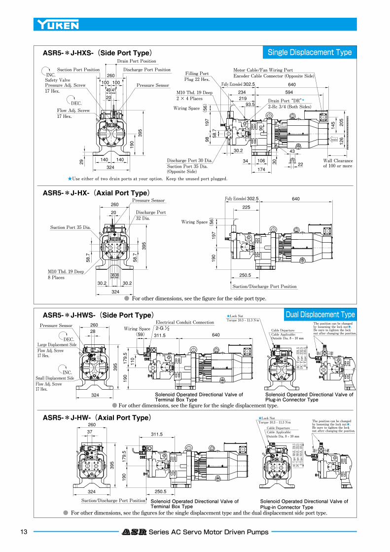
Single Displacement Type
Dual Displacement Type
ASR5-*J-HXS-(Side Port Type)
● For other dimensions, see the figures for the single displacement type and the dual displacement side port type.
● For other dimensions, see the figure for the single displacement type.
ASR5-*J-HWS-(Side Port Type)
ASR5-*J-HW-(Axial Port Type)
ASR5-*J-HX-(Axial Port Type)
● For other dimensions, see the figure for the side port type.

190
29
324
42.9
77.8
140 140
6868
12.5
260
105 105
319311
220
190
85
68
295
M12 Thd. 19 Deep 4 Places
Suction Port 48 Dia.
AC Type: 244.5
DC Type: 255.5
R Type: 258.5
★Lock NutTorque 10.3 - 11.3 N·m
Cable DepartureCable Applicable:Outside Dia. 8 - 10 mm
The position can be changed by loosening the lock nut★. Be sure to tighten the lock nut after changing the position.
AC Type: 244.5DC Type: 255.5R Type: 258.5
★Lock NutTorque 10.3 - 11.3 N·m
Cable DepartureCable Applicable: Outside Dia. 8 - 10 mm
The position can be changed by loosening the lock nut★. Be sure to tighten the lock nut after changing the position.
Solenoid Operated Directional Valve of Terminal Box Type Solenoid Operated Directional Valve of Plug-in Connector Type
Solenoid Operated Directional Valve of Terminal Box Type Solenoid Operated Directional Valve of Plug-in Connector Type
Fully Extended 378 A
319
297.5
168.5
113
B
C
145
106
174
34
30.2
30 22
43
205
126
Filling PortPlug 27 Hex.
Drain Port“DR”★
2-Rc 3/4 (Both Sides)Motor Cable/Fan Wiring PortEncoder Cable Connector (Opposite Side)
Case Drain Port14 Hex.
Discharge Port 32 Dia.
Exhaust
Intake
Wall Clearance
Suction Port Position Discharge Port Position
M10 Thd. 19 Deep 4 Places
Drain Port Position
Pressure Sensor
Filling PortPlug 14 Hex.
297 (Opposite Side)
Fully Extended 407
Suction Port Position48 Dia.
Discharge Port Position32 Dia.
Drain Port“DR” Rc 3/4
Pressure SensorElectrical Conduit Connection 2-G 1/2
Fully Extended 407
Pressure Sensor
Drain Port Position
Flow Adj. Screw17 Hex.
Safety Valve Pressure Adj. Screw 17 Hex.
WiringSpace
222
211113
211.5
395
324
319
324
202.5324
395
130
168.5
Wiring Space
Wiring Space
(56)
(56)
Fully Extended 378
(56)
Y
Y
Large Displacement Side Flow Adj. Screw17 Hex.
DEC.
Small Displacement Side Flow Adj. Screw24 Hex.
INC.
Large Displacement Side Flow Adj. Screw
DEC.
Small Displacement Side Flow Adj. Screw
INC.
Flow Adj. Screw17 Hex.
DEC.
222
Safety Valve Pressure Adj. Screw 17 Hex.
INC.
View Arrow X
127 58.7
★Use either of two drain ports at your option. Keep the unused port plugged.
ASR10-*J-H*A-
ASR10-*M-H*A-
640Model Numbers
597 100 or more700 657 150 or more
A B C
17 Hex. 24 Hex.
X190
29
324
42.9
77.8
140 140
6868
12.5
260
105 105
319311
220
190
85
68
295
M12 Thd. 19 Deep 4 Places
Suction Port 48 Dia.
AC Type: 244.5
DC Type: 255.5
R Type: 258.5
★Lock NutTorque 10.3 - 11.3 N·m
Cable DepartureCable Applicable:Outside Dia. 8 - 10 mm
The position can be changed by loosening the lock nut★. Be sure to tighten the lock nut after changing the position.
AC Type: 244.5DC Type: 255.5R Type: 258.5
★Lock NutTorque 10.3 - 11.3 N·m
Cable DepartureCable Applicable: Outside Dia. 8 - 10 mm
The position can be changed by loosening the lock nut★. Be sure to tighten the lock nut after changing the position.
Solenoid Operated Directional Valve of Terminal Box Type Solenoid Operated Directional Valve of Plug-in Connector Type
Solenoid Operated Directional Valve of Terminal Box Type Solenoid Operated Directional Valve of Plug-in Connector Type
Fully Extended 378 A
319
297.5
168.5
113
B
C
145
106
174
34
30.2
30 22
43
205
126
Filling PortPlug 27 Hex.
Drain Port“DR”★
2-Rc 3/4 (Both Sides)Motor Cable/Fan Wiring PortEncoder Cable Connector (Opposite Side)
Case Drain Port14 Hex.
Discharge Port 32 Dia.
Exhaust
Intake
Wall Clearance
Suction Port Position Discharge Port Position
M10 Thd. 19 Deep 4 Places
Drain Port Position
Pressure Sensor
Filling PortPlug 14 Hex.
297 (Opposite Side)
Fully Extended 407
Suction Port Position48 Dia.
Discharge Port Position32 Dia.
Drain Port“DR” Rc 3/4
Pressure SensorElectrical Conduit Connection 2-G 1/2
Fully Extended 407
Pressure Sensor
Drain Port Position
Flow Adj. Screw17 Hex.
Safety Valve Pressure Adj. Screw 17 Hex.
WiringSpace
222
211113
211.5
395
324
319
324
202.5324
395
130
168.5
Wiring Space
Wiring Space
(56)
(56)
Fully Extended 378
(56)
Y
Y
Large Displacement Side Flow Adj. Screw17 Hex.
DEC.
Small Displacement Side Flow Adj. Screw24 Hex.
INC.
Large Displacement Side Flow Adj. Screw
DEC.
Small Displacement Side Flow Adj. Screw
INC.
Flow Adj. Screw17 Hex.
DEC.
222
Safety Valve Pressure Adj. Screw 17 Hex.
INC.
View Arrow X
127 58.7
★Use either of two drain ports at your option. Keep the unused port plugged.
ASR10-*J-H*A-
ASR10-*M-H*A-
640Model Numbers
597 100 or more700 657 150 or more
A B C
17 Hex. 24 Hex.
X
190
29
324
42.9
77.8
140 140
6868
12.5
260
105 105
319311
220
190
85
68
295
M12 Thd. 19 Deep 4 Places
Suction Port 48 Dia.
AC Type: 244.5
DC Type: 255.5
R Type: 258.5
★Lock NutTorque 10.3 - 11.3 N·m
Cable DepartureCable Applicable:Outside Dia. 8 - 10 mm
The position can be changed by loosening the lock nut★. Be sure to tighten the lock nut after changing the position.
AC Type: 244.5DC Type: 255.5R Type: 258.5
★Lock NutTorque 10.3 - 11.3 N·m
Cable DepartureCable Applicable: Outside Dia. 8 - 10 mm
The position can be changed by loosening the lock nut★. Be sure to tighten the lock nut after changing the position.
Solenoid Operated Directional Valve of Terminal Box Type Solenoid Operated Directional Valve of Plug-in Connector Type
Solenoid Operated Directional Valve of Terminal Box Type Solenoid Operated Directional Valve of Plug-in Connector Type
Fully Extended 378 A
319
297.5
168.5
113
B
C
145
106
174
34
30.2
30 22
43
205
126
Filling PortPlug 27 Hex.
Drain Port“DR”★
2-Rc 3/4 (Both Sides)Motor Cable/Fan Wiring PortEncoder Cable Connector (Opposite Side)
Case Drain Port14 Hex.
Discharge Port 32 Dia.
Exhaust
Intake
Wall Clearance
Suction Port Position Discharge Port Position
M10 Thd. 19 Deep 4 Places
Drain Port Position
Pressure Sensor
Filling PortPlug 14 Hex.
297 (Opposite Side)
Fully Extended 407
Suction Port Position48 Dia.
Discharge Port Position32 Dia.
Drain Port“DR” Rc 3/4
Pressure SensorElectrical Conduit Connection 2-G 1/2
Fully Extended 407
Pressure Sensor
Drain Port Position
Flow Adj. Screw17 Hex.
Safety Valve Pressure Adj. Screw 17 Hex.
WiringSpace
222
211113
211.5
395
324
319
324
202.5324
395
130
168.5
Wiring Space
Wiring Space
(56)
(56)
Fully Extended 378
(56)
Y
Y
Large Displacement Side Flow Adj. Screw17 Hex.
DEC.
Small Displacement Side Flow Adj. Screw24 Hex.
INC.
Large Displacement Side Flow Adj. Screw
DEC.
Small Displacement Side Flow Adj. Screw
INC.
Flow Adj. Screw17 Hex.
DEC.
222
Safety Valve Pressure Adj. Screw 17 Hex.
INC.
View Arrow X127 58.7
★Use either of two drain ports at your option. Keep the unused port plugged.
ASR10-*J-H*A-
ASR10-*M-H*A-
640Model Numbers
597 100 or more700 657 150 or more
A B C
17 Hex. 24 Hex.
X
14ASR Series AC Servo Motor Driven Pumps
● For other dimensions, see the figure for the horizontal type.
Single Displacement Type
Dual Displacement Type
ASR10-**-HXA-(Horizontal Type)
ASR10-**-HXB-(Vertical Type)
ASR10-**-HWA-(Horizontal Type) ● For other dimensions, see the figure for the single displacement type.
ASR10-**-HWB-(Vertical Type)● For other dimensions, see the figures for the single displacement type and the dual displacement horizontal type.
15 AMSR Controller
AMSR Controller
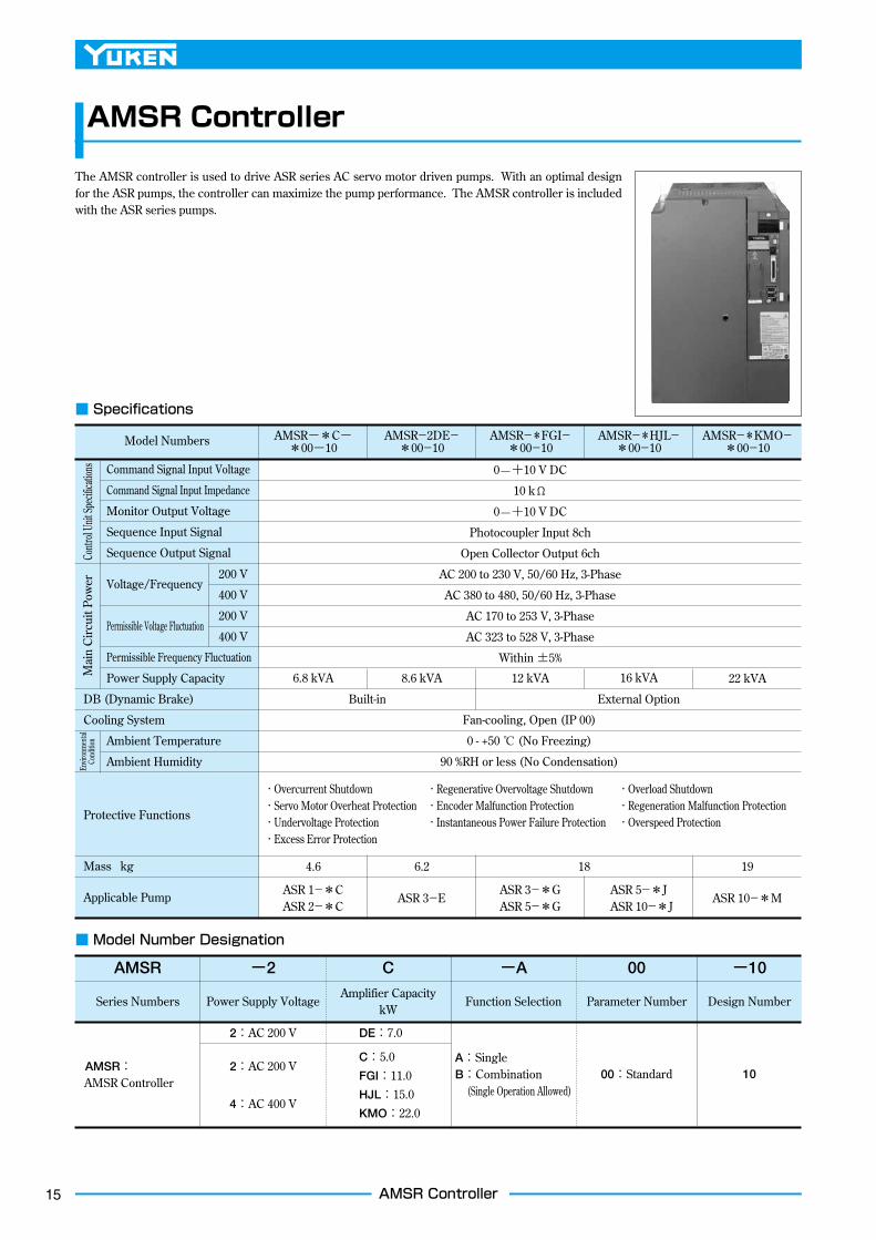
■ Specifications
Command Signal Input Voltage
Command Signal Input Impedance
Monitor Output Voltage
Sequence Input Signal
Sequence Output Signal
Voltage/Frequency
Permissible Voltage Fluctuation
Permissible Frequency Fluctuation
Power Supply Capacity
DB (Dynamic Brake)
Cooling System
Ambient Temperature
Ambient Humidity
Protective Functions
Mass kg
Applicable Pump
Model Numbers
6.8 kVA
6.24.6 18 19
8.6 kVA 12 kVA 16 kVA 22 kVA
Fan-cooling, Open (IP 00)
0 - +50 ℃ (No Freezing)
90 %RH or less (No Condensation)
・Overcurrent Shutdown ・Regenerative Overvoltage Shutdown ・Overload Shutdown・Servo Motor Overheat Protection ・Encoder Malfunction Protection ・Regeneration Malfunction Protection・Undervoltage Protection ・Instantaneous Power Failure Protection ・Overspeed Protection ・Excess Error Protection
ASR 1−*CASR 2−*C
ASR 3−EASR 3−*GASR 5−*G
ASR 5−*J ASR 10−*J
ASR 10−*M
Built-in External Option
AMSR−*C−*00−10
AMSR−2DE−*00−10
AMSR−*FGI−*00−10
AMSR−*HJL−*00−10
AMSR−*KMO−*00−10
200 V
400 V
200 V
400 V
0—+10 V DC
10 kΩ
0—+10 V DC
Photocoupler Input 8ch
Open Collector Output 6ch
AC 200 to 230 V, 50/60 Hz, 3-Phase
AC 380 to 480, 50/60 Hz, 3-Phase
AC 170 to 253 V, 3-Phase
AC 323 to 528 V, 3-Phase
Within ±5%
The AMSR controller is used to drive ASR series AC servo motor driven pumps. With an optimal design for the ASR pumps, the controller can maximize the pump performance. The AMSR controller is included with the ASR series pumps.
Series Numbers
AMSR: AMSR Controller
10
AMSR
2:AC 200 V
2:AC 200 V
4:AC 400 V
DE:7.0
C:5.0FGI:11.0HJL:15.0KMO:22.0
A: SingleB:Combination (Single Operation Allowed)
00:Standard
Power Supply VoltageAmplifier Capacity
kWFunction Selection Parameter Number Design Number
−2 C −A 00 −10
■ Model Number Designation
Contr
ol Un
it Spe
cifica
tions
Mai
n C
ircui
t Pow
erEn
viron
menta
l Co
nditio
n
16AMSR Controller
L1 L2 L3 U V WP C
L11 L21 P1N P2
L1 L2 L3 U V WP C
P1N P2
L11 L21
Terminal ScrewTorque
L1,L2,L3,P,C,U,V,W,P1,P2 L11,L21M4
1.2[Nm]M3.5
0.8[Nm]
Terminal ScrewTorque
L1,L2,L3,P,C,U,V,W,P1,P2 L11,L21M4
1.2[Nm]M3.50.8[Nm]
L1 L2 L3 U V WP1 P C ・ ・ ・
L11 L21
MODEL
MFG NO.
MADE IN JAPANYUKEN KOGYO CO.,LTD
E5010- A-10
0001-07
MR-J3-500A
CN4
CN2L
CN2
CN1
CN3
CN6
CN5
CN11
WARING
CAUTION
MODEL
MFG NO.
MADE IN JAPANYUKEN KOGYO CO.,LTD
E5010- A-10
0001-07
MR-J3-700A□-□
CN2L
CN4
CN2
CN1
CN3
CN5
CN6
CN11
WARING
CAUTION
MODEL
MFG NO.
MADE IN JAPANYUKEN KOGYO CO.,LTD
E5010- A-10
0001-07
MR-J3-11KA
CN5
CN6
CN3
CN4
CN2L
CN2
CN1
CN11
CHARGE
WARING
CAUTION
Mounting Hole Dimensions
Mounting Hole Dimensions
Mounting Hole Dimensions
Terminal Signal Assignment
Terminal Signal Assignment
Terminal Signal Assignment
CHARGE
AMSR-※C-※-10
MODEL
YUKEN KOGYO CO.,LTD. JAPAN
MFG NO.
R
EK411174-6
AMSR-※DE-※-10
MODEL
YUKEN KOGYO CO.,LTD. JAPAN
MFG NO.
R
EK411174-6
AMSR-※FGI-※-10
MODEL
YUKEN KOGYO CO.,LTD. JAPAN
MFG NO.
R
EK411174-6
R
R
R
CN4
CN2L
CN2
CN6
CN5
CN11
SW12
SW11
CN12
CN13
MON
0FE
DCB
A 9 8 7
6
543
21
12
34
ON
CN4
CN2L
CN2
CN6
CN5
CN11
SW12
SW11
CN12
CN13
MON
0FE
DCB
A 9 8 7
6
543
21
12
34
ON
CN5
CN6
CN4
CN2L
CN2
CN11
SW12
SW11
CN12
CN13
MON
0FE
DCB
A 9 8 7
6
543
21
12
34
ON
UP
DOWN
10 mm ormore
10 mm ormore
10 mm ormore
10 mm ormore
40 mm or
more
40 mm or
more
120 mm or
more
40 mm or
more
UP
DOWN
Fan
Fan Direction
(Wiring Space) A250
300
Fan
Fan Direction
(Wiring Space)A
Fan Direction
(Wiring Space)
A
M5 Thd. 4 Places
(250)
235 ±0.5
(300)
285 ±0.5
(7.5)
(6)118±0.5
80 200 140
80 200 182
80 260 260
A
A
A
400
(130)
M5 Thd. 4 Places
M10 Thd. 4 Places
160±0.5(6)
(172)
236±0.5
(260)
(7.5)
(400)
376±0.5
(12)
(12)
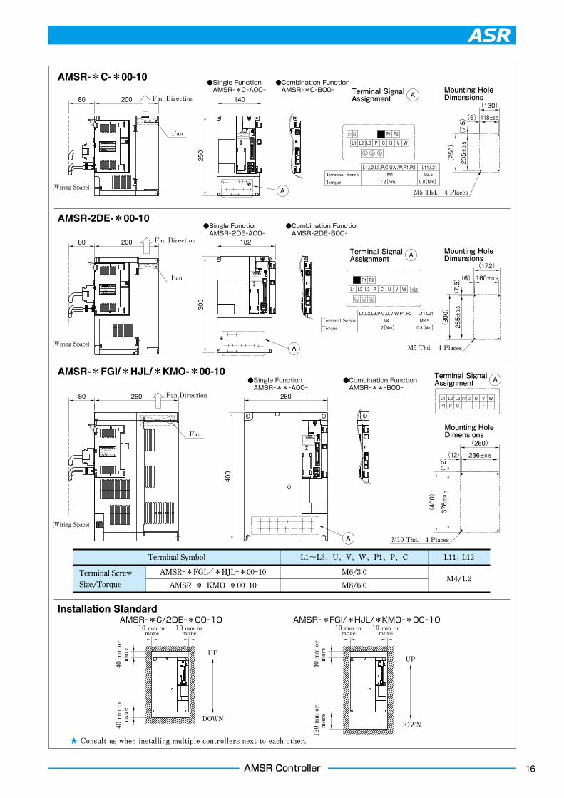
Installation Standard
AMSR-*C-*00-10
AMSR-2DE-*00-10
AMSR-*FGI/*HJL/*KMO-*00-10
AMSR-*C/2DE-*00-10
●Single Function AMSR-**-A00-
●Combination Function AMSR-**-B00-
●Single Function AMSR-2DE-A00-
●Combination Function AMSR-2DE-B00-
●Single Function AMSR-*C-A00-
●Combination Function AMSR-*C-B00-
AMSR-*FGI/*HJL/*KMO-*00-10
★ Consult us when installing multiple controllers next to each other.
Fan
Terminal Screw Size/Torque
Terminal Symbol L1〜L3、U、V、W、P1、P、C L11、 L12
AMSR−*FGI/*HJL−*00−10
AMSR−*−KMO−*00−10
M6/3.0
M8/6.0M4/1.2
17 AMSR Controller
SW12Communication Channel Setting
SW11Function Setting
CN12,13Network Connection
MR-J3-500A
CN4
CN2L
CN2
CN1
CN3
CN6
CN5
CN11
WARING
CAUTION
CN4
CN2L
CN2
CN6
CN5
CN11
SW12
SW11
CN12
CN13
MON
AMSR-※C-※※-10
MODEL
YUKEN KOGYO CO.,LTD. JAPAN
MFG NO.
R
EK411174-6
0FE
DCB
A 9 8 7
6
543
21
12
34
ON
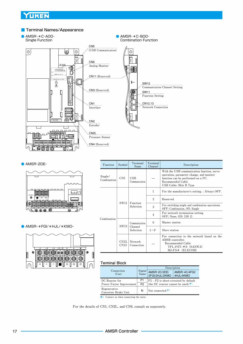
CN2LPressure Sensor
CN2Encoder
CN1Interface
CN3 (Reserved)
CN6Analog Monitor
CN5 (USB Communication)
CN11 (Reserved)
CN4 (Reserved)
Terminal Block
Connection (Use)
DC Reactor for Power Factor Improvement
Regenerative Converter Brake Unit
SignalName
P1P2
N Not connected.★1
P1 - P2 is short-circuited by default (the DC reactor cannot be used).★1
AMSR-2C/2DE/2FGI/2HJL/2KMO
AMSR-4C/4FGI/4HJL/4KMO
Description
★1 Contact us when connecting the units.
Function
For the details of CN1, CN2L, and CN6, consult us separately.
Symbol TerminalName
TerminalChannel Description
Single/Combination CN5
1
2
3
4
0
1~F
USBCommunication
Combination
SW11
SW12
CN12,CN13
Function Selection
Communication Channel Selection
Network Connection
■ Terminal Names/Appearance
● AMSR-*C-A00- Single Function
● AMSR-2DE-
● AMSR-*FGI/*HJL/*KMO-
● AMSR-*C-B00- Combination Function
With the USB communication function, servo operation, parameter change, and monitor function can be performed on a PC.Recommended CableUSB Cable: Mini B Type
For connection to the network based on the AMSR controller. Recommended Cable TFL-FST-*S(SANWA) MJ-FS*(ELECOM)
For the manufacturer’s setting. : Always OFF.
Reserved.
For switching single and combination operations.OFF: Combination, ON: SingleFor network termination setting.OFF: None, ON: 150 Ω
Master station
Slave station
18AMSR Controller
★ Included with the ASR pump.
54599-10109(MOLEX)
54599-10109(MOLEX)
7SG 2 1No.127
SignalPower +CommonOutput
ColorRedBlackWhite
★ Included with the ASR pump.
7SG 2 1No.127
SignalPower +CommonOutput
ColorRedBlackWhite
Pressure Sensor Connector Ass'y
Pressure Sensor Connector Ass'y
Pressure Sensor ConnectorPressure Sensor Connector
7:Output
2:Common
1:Power +
SG:Shield Connection to the Pump
7:Output
2:Common
1:Power +
SG:Shield Connection to the Pump
2
1
4
3 5
6
7
8
9
10
2
1
4
3 5
6
7
8
9
10
Driver Cable ★2
DC24VSOL b“OFF” : Large Displacement Side“ON” : Small Displacement Side
Motor Connector Wiring
Details of Solenoid OperatedDirectional Valve Terminal BlockTerminal Box Type
Plug-in Connector Type
Earth Terminal
Earth Terminal
Power Terminal
Power Terminal
A
BC
D
Solenoid Operated Directional Valve CableNot included. Prepare it separately.
Be sure to provide grounding.
Be sure to provide grounding.
PressureSensor
Solenoid OperatedDirectional Valve
DC24VSOL b“OFF” : Large Displacement Side“ON” : Small Displacement Side
Solenoid Operated Directional Valve
Solenoid Operated DirectionalValve Terminal Block
See “Details of SolenoidOperated DirectionalValve Terminal Block”.
Power TerminalPower Terminal
Dual Displacement Type Single Displacement Type Dual Displacement Type Single Displacement Type
Encoder Cable★2
Driver Cable★2
Pressure Sensor
Earth Terminal (M6)
Monitor PowerTerminal Block(M8)
Pressure Sensor Cable★2
Cooling Fan Terminal (M4)BU、BV、BW
Cooling Fan CableNot included.Prepare it separately.
Encoder Cable★2
D
A
CBU-PhaseV-PhaseW-PhaseFG (Frame Ground)
Series Connection
Power Input Power Input
Motor Cable★2
Motor Cable★2
Pressure Sensor Cable★2
AMSR ControllerDynamic BrakeAMSR ControllerDynamic BrakeOnly for ASR3-*G and ASR5-*G
Series Connection
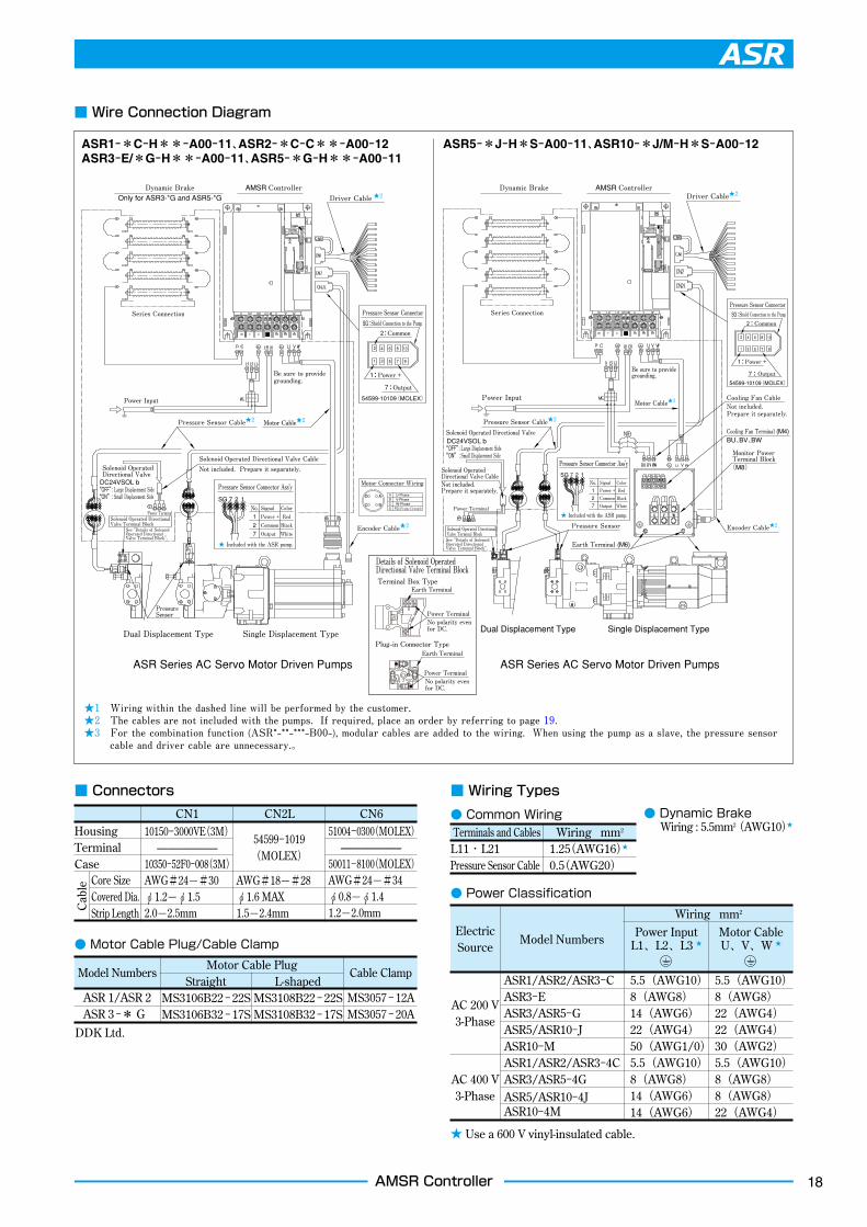
■ Wire Connection Diagram
ASR1-*C-H**-A00-11、ASR2-*C-C**-A00-12ASR3-E/*G-H**-A00-11、ASR5-*G-H**-A00-11
ASR5-*J-H*S-A00-11、ASR10-*J/M-H*S-A00-12
ASR Series AC Servo Motor Driven Pumps ASR Series AC Servo Motor Driven Pumps
★1 Wiring within the dashed line will be performed by the customer.★2 The cables are not included with the pumps. If required, place an order by referring to page 19.★3 For the combination function (ASR*-**-***-B00-), modular cables are added to the wiring. When using the pump as a slave, the pressure sensor
cable and driver cable are unnecessary.。
Solenoid Operated Directional Valve CableNot included. Prepare it separately.
Solenoid Operated DirectionalValve Terminal BlockSee “Details of SolenoidOperated DirectionalValve Terminal Block”.
No polarity even for DC.
No polarity even for DC.
● Dynamic BrakeWiring : 5.5mm2(AWG10)★
■ Wiring Types
● Common Wiring
■ Connectors
★ Use a 600 V vinyl-insulated cable.
Electric Source
Model Numbers Power InputL1、L2、L3 ★
Wiring mm2
Motor CableU、V、W ★
● Power Classification
AC 200 V 3-Phase
AC 400 V 3-Phase
ASR1/ASR2/ASR3−CASR3−EASR3/ASR5−GASR5/ASR10−JASR10−MASR1/ASR2/ASR3−4CASR3/ASR5−4GASR5/ASR10−4JASR10−4M
5.5(AWG10)8(AWG8)14(AWG6)22(AWG4)50(AWG1/0)5.5(AWG10)8(AWG8)14(AWG6)14(AWG6)
5.5(AWG10)8(AWG8)22(AWG4)22(AWG4)30(AWG2)5.5(AWG10)8(AWG8)8(AWG8)22(AWG4)
Model NumbersMotor Cable Plug
StraightMS3106B22 − 22SMS3106B32 − 17S
DDK Ltd.
L-shapedMS3108B22 − 22SMS3108B32 − 17S
Cable Clamp
MS3057 − 12AMS3057 − 20A
● Motor Cable Plug/Cable Clamp
ASR 1/ASR 2 ASR 3 −* G
CN1 CN2L10150−3000VE(3M)
——————10350−52F0−008(3M)AWG#24—#30φ1.2—φ1.52.0—2.5mm
54599−1019(MOLEX)
AWG#18—#28φ1.6 MAX1.5—2.4mm
CN651004−0300(MOLEX)
——————50011−8100(MOLEX)AWG#24—#34φ0.8—φ1.41.2—2.0mm
HousingTerminalCase
Cab
le Core SizeCovered Dia.Strip Length
Terminals and Cables Wiring mm2
1.25(AWG16)★
0.5(AWG20)L11・L21Pressure Sensor Cable

19 AMSR Controller
Do not disconnect the connector bar.
Keep a distance of 70 mm or more between neighboring brake units.
Series Connection
Fan (1.0 m3/min, □92 × 2 units)★
5.5 Dia. 8.2 Dia.-
P1PC
Model Model
★1.Dynamic brakes are included with the ASR pumps.★2.Dynamic brakes may become excessively heated. Use heat-resistant and fireproof wires and avoid their contact with the brakes.
★Recommended fan capacity for fan cooling. In this case, change the setting of parameter No. PA02 from “0000” to
“00FA”.
■ Cable NumbersThe cables are not included with the ASR pumps. If required, place an order by referring to the list below. The cables other than the motor cable are common for all models.
● Motor Cable
● Driver Cable/Encoder Cable/Pressure Sensor Cable
●Connection
■ Dynamic Brake
● Specifications
ASR Pump Model Numbers Cable Model Numbers Remarks
ASR 1−*C−H**−*00−11YSDC−M1−29−☆−★−10
☆:Plug Type
S:Straight, L:L-shaped
★:Cable Length
03: 3 m 05: 5 m 10:10 m
15:15 m 20:20 m 30:30 m
N:Plug and cable clamp only
ASR 2−*C−C**−*00−12
ASR 3−E−H**−*00−11 YSDC−M1−44S−☆−★−10
ASR 3−G−H**−*00−11 YSDC−M1−1A−☆−★−10
ASR 3−4G−H**−*00−11 YSDC−M1−44S−☆−★−10
ASR 5−G−H**−*00−11 YSDC−M1−1A−☆−★−10
ASR 5−4G−H**−*00−11 YSDC−M1−44S−☆−★−10
AMSR Controller Model Numbers
Dynamic Brake Model Qty.Permissible
RegenerationW
Regeneration with Fan
WResistance
ΩMass
kg
AMSR−2FGI− GRZG400−1.5Ω 4 500 800 6(1.5Ω×4) 3.2(0.8kg×4)
AMSR−2HJL− GRZG400−0.9Ω5 850 1300
4.5(0.9Ω×5) 4.0(0.8kg×5)
AMSR−2KMO− GRZG400−0.6Ω 3(0.6Ω×5)
AMSR−4FGI− GRZG400−5.0Ω 4 500 800 20(5.0Ω×4) 3.2(0.8kg×4)
AMSR−4HJL− GRZG400−2.5Ω5 850 1300
12.5(2.5Ω×5) 4.0(0.8kg×5)
AMSR−4KMO− GRZG400−2.0Ω 10(2.0Ω×5)
Cable Type Cable Model Numbers Remarks
Driver Cable YSDC−D14−00−★−10 ★:Cable Length 01: 1 m 02: 2 m 03: 3 m 05: 5 m 10:10 m 20:20 m
Encoder Cable YSDC−E7−S−★−10 ★:Cable Length 02: 2 m 05: 5 m 10:10 m
Pressure Sensor Cable Consult us separately.
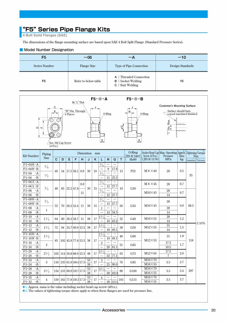
20Accessories
Rc“L”Thd.Costomer’s Mounting Surface
“T”Dia. Max.
F
E
C J
D
O-RingSurface should have a good machined finished.
φQ
O-Ring
K
"H" Dia. Through4 Places
Soc. Hd Cap Screw(4 Pcs.)
J
N
K
■ Model Number Designation
F5
Series Number Flange Size Type of Pipe Connection
A:Threaded ConnectionB:Socket WeldingC:Butt Welding
10
Design Standards
−06 −A −10
F5 Refer to below table
The dimensions of the flange mounting surface are based upon SAE 4 Bolt Split Flange (Standard Pressure Series).
3/8
1/2
3/4
3/4
1
11/4
11/2
11/2
2
21/2
3
31/2
4
40
48
55
64
72
85
102
116
134
150
13
19
26
32
38
48
51
63
76
88
101
P22
G30
G35
G40
G50
G60
G65
G75
G85
G100
G115
M 8 ×40
M 8 ×45
M10×45
M10×45
M10×55
M12×55
M12×55
M12×65
M16×70M16×55M16×70M16×55M16×70M16×55
28
28
2814
28
281428142114
21
17.510.517.5
7
3.5
3.5
3.5
0.5
0.7
0.7
0.9
1.2
1.5
1.8
1.7
2.0
2.7
3.4
3.7
35
68.5
118
287
±10%
54
65
70
80
94
102
114
135
153
162
17.5
22.2
26.2
30.2
35.7
42.9
50.8
61.9
69.9
77.8
38.1
47.6
52.4
58.7
69.9
77.8
88.9
106.4
120.7
130.2
10
15
15
17
17
17
17
17
17
17
3/8
−1/2
−3/4
−3/4
−3/4
−1
−11/4
−11/2
−11/2
−2
−21/2
−3
−31/2
−4
−
−9
−11−12−12−12−14−16−18−18−20−22−25−28−28
−17.8−
22.2−
27.7−
27.7−
27.7−
34.5−
43.2−
49.1−
49.1−
61.1−
77.1−
90.0−
102.8−
115.5
30
30
30
38
38
38
48
533853385338
8.8
8.8
11
11
11
13.5
13.5
13.5
17.5
17.5
17.5
Kit Number Piping Size
Dimention mm O-RingJIS B 2401
Hs90
Socket Head Cap Screw (4 Pcs.)
(JIS B 1176)
Max. Operating Pressure
MPa
Approx. Masskg
Tightening ToruqueNm
Recommendation ToleranceC D E F H J K L N Q T( )
★1. Approx. mass is the value including socket head cap screw (4Pcs.).★2. The values of tightening torque above apply to when these flanges are used for pressure line.
F5−※−A F5−※−B
F5−04W−AF5−04W−BF5−04 −AF5−04 −BF5−06X−AF5−06X−BF5−06 −AF5−06 −BF5−08W−AF5−08W−BF5−08 −AF5−08 −BF5−10 −AF5−10 −BF5−12 −AF5−12 −BF5−16W−AF5−16W−BF5−16 −AF5−16 −BF5−20 −AF5−20 −BF5−24 −AF5−24 −BF5−28 −AF5−28 −BF5−32 −AF5−32 −B
“F5” Series Pipe Flange Kits4 Bolt Solid Flanges (SAE)
★1 ★2
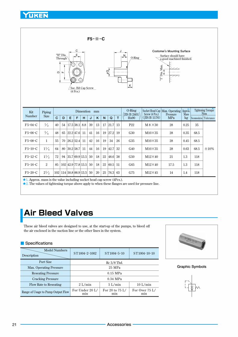
21
F
E
C
DO-Ring
φQ
K
"H" Dia. Through
Soc. Hd Cap Screw(4 Pcs.)
J
N
Costomer’s Mounting Surface
“T”Dia. Max.
Surface should have a good machined finished.
F5−※−C
Kit Number
F5−04−C
F5−06−C
F5−08−C
F5−10−C
F5−12−C
F5−16−C
F5−20−C
1/2
3/4
1
11/4
11/2
2
21/2
40
48
55
64
72
85
102
54
65
70
80
94
102
114
17.5
22.2
26.2
30.2
35.7
42.9
50.8
38.1
47.6
52.4
58.7
69.9
77.8
88.9
8.8
11
11
11
13.5
13.5
13.5
39
41
42
44
50
50
50
13
16
16
16
18
18
20
17
19
19
19
22
22
25
21.7
27.2
34
42.7
48.6
60.5
76.3
13
19
26
32
38
51
63
P22
G30
G35
G40
G50
G65
G75
M 8 ×30
M10×35
M10×35
M10×35
M12×40
M12×40
M12×45
28
28
28
28
21
17.5
14
0.25
0.35
0.45
0.63
1.3
1.3
1.4
35
68.5
68.5
68.5
118
118
118
±10%
Piping Size
Dimention mm
C D E F H J K N Q T( )
★1. Approx. mass is the value including socket head cap screw (4Pcs.).★2. The values of tightening torque above apply to when these flanges are used for pressure line.
■ Specifications
Model NumbersS T 1004−2−1002 S T 1004−5−10 S T 1004−10−10Description
Port Size Rc 3/8 Thd.25 MPa
0.15 MPa
0.34 MPa
2 L/min
For Under 20 L/min
For 20 to 75 L/min
For Over 75 L/min
5 L/min 10 L/min
Max. Operating Pressure
Reseating Pressure
Cracking Pressure
Flow Rate to Reseating
Range of Usage to Pump Output Flow
These air bleed valves are designed to use, at the start-up of the pumps, to bleed off the air enclosed in the suction line or the other lines in the system.
Graphic Symbols
Air Bleed Valves
Accessories
O-RingJIS B 2401
Hs90
Socket Head Cap Screw (4 Pcs.)
(JIS B 1176)
Max. Operating Pressure
MPa
Approx. Masskg
Tightening ToruqueNm
Recommendation Tolerance
★1 ★2

AC Servo Motor Driven Pumps CatalogueApril, 2014 Second Edition
Published
Yuken Kogyo Co., Ltd.Sales Planning SectionSales Planning Dept.4-8, Shiba-Daimon 1 Chome, Minato-ku, Tokyo 105-0012, JapanTEL. +81-3-3432-2113FAX. +81-3-3436-2344
PrinterSee code number on back cover
Please address your inquiries regarding this catalogue to the International Sales Department.TEL. +81-467-77-3111FAX. +81-467-77-3115
ASR
140430 TPrinted in Japan
International Sales Department (Sagami office):4-4-34, Kamitsuchidana-Naka
Ayase, Kanagawa 252-1113, Japan
Telephone : +81-467-77-3111 E-mail : [email protected] : +81-467-77-3115 URL http://www.yuken.co.jp


![円弧型リニアサーボモータ Arc type Linear Servo Motor Compass Motor...5 Servo driver / Controller [ CⅡ series ] [ VCⅡseries ] Servo driver / Controller Line up VCⅡ-D](https://static.fdocuments.net/doc/165x107/60d73f7f99be0c5f5558ebe2/ffffoeff-arc-type-linear-servo-compass-motor-5-servo.jpg)


