SERIES - Amphenol Fiber Optic Products
20
Transcript of SERIES - Amphenol Fiber Optic Products

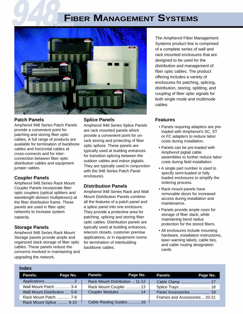
Patch PanelsAmphenol 948 Series Patch Panelsprovide a convenient point forpatching and storing fiber opticcables. A full range of products areavailable for termination of backbonecables and horizontal cables atcross-connects and for inter-connection between fiber opticdistribution cables and equipmentjumper cables.
Coupler PanelsAmphenol 948 Series Rack MountCoupler Panels incorporate fiberoptic couplers (optical splitters andwavelength division multiplexers) atthe fiber distribution frame. Thesepanels are used in fiber opticnetworks to increase systemcapacity.
Storage PanelsAmphenol 948 Series Rack MountStorage panels provide ample andorganized slack storage of fiber opticcables. These panels reduce theconcerns involved in maintaining andupgrading the network.
Splice PanelsAmphenol 948 Series Splice Panelsare rack mounted panels whichprovide a convenient point for on-rack storing and protecting of fiberoptic splices. These panels aretypically used at building entrancesfor transition splicing between theoutdoor cables and indoor pigtails.They are typically used in conjunctionwith the 948 Series Patch Panelenclosures.
Distribution PanelsAmphenol 948 Series Rack and WallMount Distribution Panels combineall the features of a patch panel anda splice panel into one enclosure.They provide a protective area forpatching, splicing and storing fiberoptic cables. Distribution panels aretypically used at building entrances,telecom closets, customer premiseapplications, or in equipment roomsfor termination of interbuildingbackbone cables.
The Amphenol Fiber ManagementSystems product line is comprisedof a complete series of wall andrack mounted enclosures that aredesigned to be used for thedistribution and management offiber optic cables. The productoffering includes a variety ofenclosures for patching, splicing,distribution, storing, splitting, andcoupling of fiber optic signals forboth single mode and multimodecables.
IndexPanels: Page No.
Rack Mount Distribution ... 11-12Rack Mount Coupler .............13Coupler Modules ...................14
Cable Routing Guides ...........16
948SERIES
Features• Panels requiring adapters are pre-
loaded with Amphenol’s SC, STor FC adapters to reduce laborcosts during installation.
• Panels can be pre-loaded withAmphenol pigtail cableassemblies to further reduce laborcosts during field installation.
• A single part number is used tospecify semi-loaded or fullyloaded enclosures to simplify theordering process.
• Rack mount panels haveremovable doors for increasedaccess during installation andmaintenance.
• Panels provide ample room forstorage of fiber slack, whilemaintaining bend radiusprotection for the stored fibers.
• All enclosures include mountinghardware, installation instructions,laser warning labels, cable ties,and cable routing designationcards.
Panels : Page No.
Applications ..........................2Wall Mount Patch ............. 3-4Wall Mount Distribution .... 5-6Rack Mount Patch ............ 7-8Rack Mount Splice ......... 9-10
Panels: Page No.
Cable Clamp .......................... 17Splice Trays ............................ 18Panel Accessories .................. 19Frames and Accessories ... 20-21
FIBER MANAGEMENT SYSTEMS
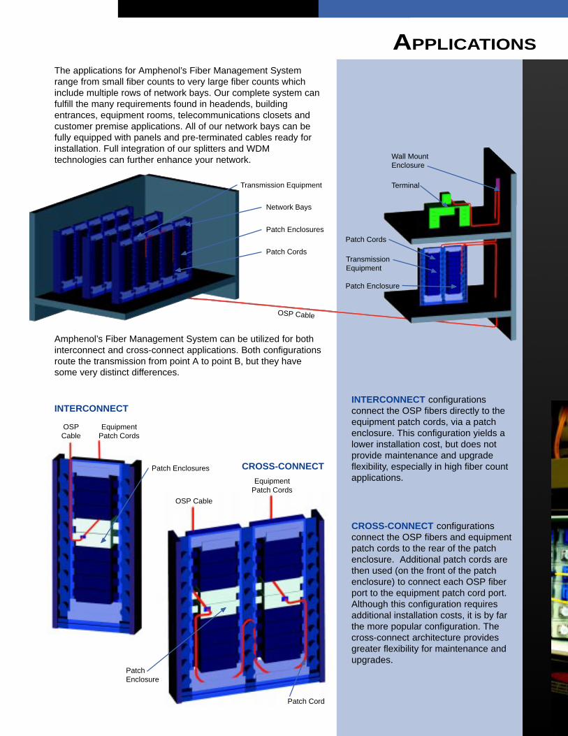
The applications for Amphenol’s Fiber Management Systemrange from small fiber counts to very large fiber counts whichinclude multiple rows of network bays. Our complete system canfulfill the many requirements found in headends, buildingentrances, equipment rooms, telecommunications closets andcustomer premise applications. All of our network bays can befully equipped with panels and pre-terminated cables ready forinstallation. Full integration of our splitters and WDMtechnologies can further enhance your network.
Amphenol’s Fiber Management System can be utilized for bothinterconnect and cross-connect applications. Both configurationsroute the transmission from point A to point B, but they havesome very distinct differences.
INTERCONNECT configurationsconnect the OSP fibers directly to theequipment patch cords, via a patchenclosure. This configuration yields alower installation cost, but does notprovide maintenance and upgradeflexibility, especially in high fiber countapplications.
CROSS-CONNECT configurationsconnect the OSP fibers and equipmentpatch cords to the rear of the patchenclosure. Additional patch cords arethen used (on the front of the patchenclosure) to connect each OSP fiberport to the equipment patch cord port.Although this configuration requiresadditional installation costs, it is by farthe more popular configuration. Thecross-connect architecture providesgreater flexibility for maintenance andupgrades.
INTERCONNECT
CROSS-CONNECT
OSPCable
EquipmentPatch Cords
Patch Enclosures
OSP Cable
EquipmentPatch Cords
PatchEnclosure
Patch Cord
▲▲▲▲▲
▲▲▲▲▲
▲▲▲▲▲
Transmission Equipment
Network Bays
Patch Enclosures
Patch CordsTransmissionEquipment
Patch Cords
Patch Enclosure
OSP Cable
Wall MountEnclosure
Terminal
▲▲▲▲▲
▲▲▲▲▲
▲▲▲▲▲
▲▲▲▲▲
▲▲▲▲▲
▲▲▲▲▲
▲▲▲▲▲
▲▲▲▲▲▲▲▲▲▲
APPLICATIONS

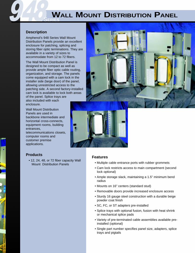
DescriptionAmphenol’s 948 Series Wall MountPatch Panels provide an excellentenclosure for patching and storing fiberoptic terminations. They are available ina variety of sizes to accommodate from12 to 72 fibers.
The Wall Mount Patch Panel isdesigned to be compact as well asprovide ample fiber optic cable routing,organization, and storage. The panelscome equipped with a cam lock in theinstaller side (large door) of the panel,allowing unrestricted access to thepatching side. A second factory-installedcam lock is available to lock both areasof the panel.
Wall Mount Patch Panels are used inbackbone, intermediate and horizontalcross-connects, equipment rooms,building entrances, telecommunicationsclosets, computer rooms and customerpremise applications.
Features• Multiple cable entrance ports with rubber grommets
• Cam lock restricts access to main compartment (secondlock optional)
• Ample storage slack, maintaining a 1.5” minimumbend radius
• Mounts on 16” centers (standard stud)
• Removable doors provide increased enclosure access
• Sturdy 16 gauge steel construction with a durable beigepowder coat finish
• SC, FC, or ST adapters pre-installed
• Variety of pre-terminated cable assemblies available pre-installed (optional)
• Single part number specifies panel size, adapters,and pigtails
Products• 12, 24, 48, or 72 fiber capacity Wall
Mount Patch Panels
948SERIESWALL MOUNT PATCH PANEL

4
Fiber Capacity
1 = 122 = 244 = 486 = 72
Connector/Adaptor Style
A = S/M SC (ceramic)B = S/M SC Duplex (ceramic)C = S/M FC Flange (ceramic)D = S/M FC D-Hole (ceramic)E = S/M FC D-Hole (angle ceramic)F = S/M ST metal body (ceramic)G = M/M SC (metal)H = M/M SC Duplex (metal)J = M/M FC Flange (metal)K = M/M FC D-Hole (metal)L = M/M ST metal body (metal)Q = S/M SC (angle ceramic)T = S/M ST polymer body (ceramic)
Pigtails
0 = No Pigtails1 = S/M Super Polish2 = S/M Ultra Polish3 = S/M Angle Polish4 = M/M 50/125 Fiber5 = M/M 62.5/125 Fiber6 = M/M 100/140 Fiber
Cable Type
A = NoneC = 3 mm Jacketed PigtailD = 12 Fiber (No Fiber Sub-Groups)E = 24 Fiber (6 Fiber Sub-Groups)F = 48 Fiber (12 Fiber Sub-Groups)G = 72 Fiber (12 Fiber Sub-Groups)
Cable LengthSpecify in meters(e.g. 05 = 5 meters)
9 4 8 - - 1 1 P 0
CAM LOCK
PRE-TERMINATED PIGTAILS
EMBOSSED MOUNTING HOLES
CABLE ROUTING GUIDES
LOADED 6-PACKS
STRAIN RELIEF / GROUND LUG
LATCH
CABLE TIE EMBOSSMENTS
ENTRANCE CABLE GROMMET
LATCH
DESIGNATION LABEL (INSIDE DOOR)
LIFT-OFF HINGES
Fiber Capacity Dimensions
12 15.2”W x 11.3”H x 3.2”D24 18.5”W x 17.2”H x 3.2”D48 18.5”W x 17.2”H x 6.2”D72 18.5”W x 17.2”H x 6.2”D
▲▲▲▲▲
▲▲▲▲▲
▲▲▲▲▲
▲▲▲▲▲
▲▲▲▲▲
▲▲▲▲▲
▲▲▲▲▲
▲▲▲▲▲▲▲▲▲▲
▲▲▲▲▲
▲▲▲▲▲
▲▲▲▲▲
DescriptionAmphenol’s 948 Series Wall MountDistribution Panels provide an excellentenclosure for patching, splicing andstoring fiber optic terminations. They areavailable in a variety of sizes toaccommodate from 12 to 72 fibers.
The Wall Mount Distribution Panel isdesigned to be compact as well asprovide ample fiber optic cable routing,organization, and storage. The panelscome equipped with a cam lock in theinstaller side (large door) of the panel,allowing unrestricted access to thepatching side. A second factory-installedcam lock is available to lock both areasof the panel. Splice trays arealso included with eachenclosure.
Wall Mount DistributionPanels are used inbackbone intermediate andhorizontal cross-connects,equipment rooms, buildingentrances,telecommunications closets,computer rooms andcustomer premiseapplications.
Products• 12, 24, 48, or 72 fiber capacity Wall
Mount Distribution Panels
Features• Multiple cable entrance ports with rubber grommets
• Cam lock restricts access to main compartment (secondlock optional)
• Ample storage slack, maintaining a 1.5” minimum bendradius
• Mounts on 16” centers (standard stud)
• Removable doors provide increased enclosure access
• Sturdy 16 gauge steel construction with a durable beigepowder coat finish
• SC, FC, or ST adapters pre-installed
• Splice trays with optional fusion, fusion with heat shrinkor mechanical splice pads
• Variety of pre-terminated cable assemblies available pre-installed (optional)
• Single part number specifies panel size, adapters, splicetrays and pigtails
948SERIESWALL MOUNT DISTRIBUTION PANEL

6
CAM LOCK
PRE-TERMINATED PIGTAILS
EMBOSSED MOUNTING HOLES
CABLE ROUTING GUIDES
STRAIN RELIEF / GROUND LUG
LATCH
CABLE TIE EMBOSSMENTS
CABLE ENTRANCE GROMMET
LATCH
DESIGNATION LABEL (INSIDE DOOR)
LIFT-OFF HINGES
Connector/Adapter Style
A = S/M SC (ceramic)B = S/M SC Duplex (ceramic)C = S/M FC Flange (ceramic)D = S/M FC D-Hole(ceramic)E = S/M FC D-Hole (angle ceramic)F = S/M ST metal body (ceramic)G = M/M SC (metal)H = M/M SC Duplex (metal)J = M/M FC Flange (metal)K = M/M FC D-Hole (metal)L = M/M ST metal body (metal)Q = S/M SC (angle ceramic)T = S/M ST polymer body (ceramic)
Pigtails
0 = No Pigtails1 = S/M Super Polish2 = S/M Ultra Polish3 = S/M Angle Polish4 = M/M 50/125 Fiber5 = M/M 62.5/125 Fiber6 = M/M 100/140 Fiber
Cable Type
A = NoneB = 900µm Buffered PigtailC = 3 mm Jacketed PigtailD = 12 Fiber (No Fiber Sub-Group)K = 900µm Jacketed Pigtail
Fiber Capacity
1 = 122 = 244 = 486 = 72
- 1 1 D
Splice Pad
1 = Fusion Splice2 = Fusion Splice w/Heat Shrink3 = Mechanical
Cable LengthSpecify in meters(eg. 05 = 5 meters)
AMPHENOL SPLICE TRAY
LOADED 6-PACKS
Fiber Capacity Dimensions
12 15.2”W x 11.3”H x3.2”D24 18.5”W x 17.2”H x 3.2”D48 18.5”W x 17.2”H x 6.2”D72 18.5”W x 17.2”H x 6.2”D
▲▲▲▲▲▲▲▲▲▲
▲▲▲▲▲
▲▲▲▲▲
▲▲▲▲▲
▲▲▲▲▲
▲▲▲▲▲
▲▲▲▲▲
▲▲▲▲▲
▲▲▲▲▲
▲▲▲▲▲▲▲▲▲▲
▲▲▲▲▲
9 4 8 -

RACK MOUNT PATCH PANEL
DescriptionAmphenol’s 948 Series Rack MountPatch Panels provide a convenientlocation for patching single mode ormultimode fiber optic cables from thecable termination point to the lightwaveequipment. They are available in avariety of sizes to accommodate from24 to 96 fibers.
The Rack Mount Patch Panels can beused in both cross-connect andinterconnect applications. Pre-terminated multi-channel fiber opticpigtails are excellent for reducinginstallation costs and installer handling.The patch panel pigtail can be quicklyand easily routed to the splicinglocation, eliminating the need forperforming field terminations.
Rack Mount Patch Panels are used inbackbone intermediate and horizontalcross-connects, equipment rooms,building entrances, headends, centraloffices and computer rooms.
Features• Smoked polycarbonate front door exposes designation
card
• Cable management organizers located in rear of theenclosure
• Mounts on 19” or 23” racks (reversible brackets)
• Removable doors provide increased enclosure access
• Sturdy 16 gauge steel construction with a durable beigepowder coat finish
• Enhanced cable routing brackets available (optional)
• SC, FC, or ST adapters pre-installed
• Variety of pre-terminated cable assemblies available pre-installed (optional)
• Single part number specifies panel size, adapters type,and pigtails
Products• 24, 48, 72 or 96 fiber capacity
Rack Mount Patch Panels
948SERIES

8
Fiber Capacity
2 = 244 = 486 = 727 = 96
- 1 2 P 0
Connector/Adapter Style
A = S/M SC (ceramic)B = S/M SC Duplex (ceramic)C = S/M FC Flange (ceramic)D = S/M FC D-Hole(ceramic)E = S/M FC D-Hole (angle ceramic)F = S/M ST metal body (ceramic)G = M/M SC (metal)H = M/M SC Duplex (metal)J = M/M FC Flange (metal)K = M/M FC D-Hole (metal)L = M/M ST metal body (metal)Q = S/M SC (angle ceramic)T = S/M ST polymer body (ceramic)
Pigtails
0 = No Pigtails1 = S/M Super Polish2 = S/M Ultra Polish3 = S/M Angle Polish4 = M/M 50/125 Fiber5 = M/M 62.5/125 Fiber6 = M/M 100/140 Fiber Cable Type
A = NoneC = 3 mm Jacketed PigtailD = 12 Fiber (No Fiber Sub-Group)E = 24 Fiber (6 Fiber Sub-Groups)F = 48 Fiber (12 Fiber Sub-Groups)G = 72 Fiber (12 Fiber Sub-Groups)H = 96 Fiber (12 Fiber Sub-Groups)
Cable LengthSpecify in meters(eg. 05 = 5 meters)
CABLE DESIGNATION CARD
POLYCARBONATE FRONT DOOR
BEND RADIUS PROTECTION
ACCESSORY MOUNTING HOLES
UNIVERSALMOUNTING BRACKET
CABLE ENTRANCE PORT
REAR DOOR
CABLE TIEEMBOSSMENTS
LOADED 6-PACKS
Fiber Capacity Dimensions
24 17.3”W x 5.3”H x11.9”D48 17.3”W x 6.8”H x11.9”D72 17.3”W x 6.8”H x11.9”D96 17.3”W x 10.8”H x11.9”D▲▲▲▲▲
▲▲▲▲▲
▲▲▲▲▲▲▲▲▲▲
▲▲▲▲▲
▲▲▲▲▲
▲▲▲▲▲
▲▲▲▲▲
▲▲▲▲▲
9 4 8 -

DescriptionAmphenol’s 948 Series Rack MountSplice Panels provide an on-racksplicing point for the OSP cable. Theyare available in two or three drawerdesigns to accommodate up to 144fibers.
The Rack Mount Splice Panelincorporates splicing within the fiberoptic network bays. These enclosuresare ideal for splicing a pre-terminatedpatch panel pigtail to the OSP cable.The enclosures provide ample fiberstorage within a removable drawer.Each drawer can accommodate up totwo splice trays for a total of 48fusion splices.
Rack Mount Splice Panels areused in backbone intermediateand horizontal cross-connects,equipment rooms, buildingentrances, headends, centraloffices and computer rooms.
Products• 48, 72, 96 or 144 fiber
capacity Rack MountDistribution Panels
• Two or three drawer designs Features• Removable splice drawers with positive stop
• Smoked polycarbonate front door exposes designationcard
• Two or three drawer designs to accommodate up to 144fibers
• Ample storage slack, maintaining a 1.5” minimum bendradius
• Splice trays may be located in a variety of positions withinthe splice drawer
• Mounts on 19” or 23” racks (reversible brackets)
• Removable doors provide increased enclosure access
• Sturdy 16 gauge steel construction with a durable beigepowder coat finish
• Splice trays with optional fusion, fusion with heat shrink, ormechanical splice pads
• Single part number specifies panel size and splice trays
RACK MOUNT SPLICE PANEL948SERIES

10
CABLE DESIGNATION CARD
POLYCARBONATE FRONT DOOR
SPLICE DRAWER
CABLE TIE EMBOSSMENTS
ACCESSORYMOUNTING HOLES
UNIVERSALMOUNTING BRACKET
CABLEENTRANCE PORT
REAR DOOR
CABLE ROUTINGGUIDES
AMPHENOLSPLICE TRAYS
DRAWER STOP
DRAWER STOP TAB
VELCRO STRAPS
LATCH
PART SPLICENUMBER CAPACITY SPLICE TYPE DRAWERS DIMENSIONS
948-402SY-10A00 48 Fusion 2 17.3”W x 5.3”H x 11.9”D
948-402SY-20A00 48 Fusion with Heat Shrink 2 17.3”W x 5.3”H x 11.9”D
948-402SY-30A00 48 Mechanical 2 17.3”W x 5.3”H x 11.9”D
948-602SY-10A00 72 Fusion 2 17.3”W x 5.3”H x 11.9”D
948-602SY-20A00 72 Fusion with heat Shrink 2 17.3”W x 5.3”H x 11.9”D
948-602SY-30A00 72 Mechanical 3 17.3”W x 6.8”H x 11.9”D
948-702SY-10A00 96 Fusion 2 17.3”W x 5.3”H x 11.9”D
948-702SY-20A00 96 Fusion with Heat Shrink 2 17.3”W x 5.3”H x 11.9”D
948-802SY-10A00 144 Fusion 3 17.3”W x 6.8”H x 11.9”D
948-802SY-20A00 144 Fusion with Heat Shrink 3 17.3”W x 6.8”H x 11.9”D
▲▲▲▲▲
▲▲▲▲▲
▲▲▲▲▲
▲▲▲▲▲
▲▲▲▲▲
▲▲▲▲▲
▲▲▲▲▲▲▲▲▲▲
▲▲▲▲▲
▲▲▲▲▲
▲▲▲▲▲▲▲▲▲▲
▲▲▲▲▲
▲▲▲▲▲

12
Connector/Adapter Style
A = S/M SC (ceramic)B = S/M SC Duplex (ceramic)C = S/M FC Flange (ceramic)D = S/M FC D-Hole (ceramic)E = S/M FC D-Hole (angle ceramic)F = S/M ST metal body (ceramic)G = M/M SC (metal)H = M/M SC Duplex (metal)J = M/M FC Flange (metal)K = M/M FC D-Hole (metal)L = M/M ST metal body (metal)Q = S/M SC (angle ceramic)T = S/M ST polymer body (metal)
Fiber Capacity
2 = 244 = 486 = 727 = 96
- 1 2 D
Splice Pad1 = Fusion Splice2 = Fusion Splice w/Heat Shrink3 = Mechanical
Pigtails0 = No Pigtails1 = S/M Super Polish2 = S/M Ultra Polish3 = S/M Angle Polish4 = M/M 50/125 Fiber5 = M/M 62.5/125 Fiber6 = M/M 100/140 Fiber
Cable TypeA = NoneB = 900µm Buffered PigtailC = 3 mm Jacketed PigtailD = 12 Fiber (No Fiber Sub-Groups)K = 900µm Jacketed Pigtail
Cable LengthSpecify in meters(eg. 05 = 5 meters)
CABLE DESIGNATION CARD
POLYCARBONATE FRONT DOOR
BEND RADIUS PROTECTION
CABLE TIE EMBOSSMENTS
ACCESSORY MOUNTING HOLES
UNIVERSALMOUNTING BRACKET
CABLEENTRANCE PORT
REAR DOOR
CABLE ROUTINGGUIDES
SPLICE DRAWER
AMPHENOLSPLICE TRAYS
9 4 8 -
LATCH
REMOVABLE DRAWERLID
VELCROSTRAP
LOADED 6-PACKS
DRAWER STOP
Fiber Capacity Dimensions
24 17.3”W x 5.3”H x 11.9”D48 17.3”W x 10.8”H x 11.9”D72 17.3”W x 10.8”H x 11.9”D96 17.3”W x 14.3”H x 11.9”D
▲▲▲▲▲
▲▲▲▲▲
▲▲▲▲▲
▲▲▲▲▲
▲▲▲▲▲
▲▲▲▲▲
▲▲▲▲▲
▲▲▲▲▲
▲▲▲▲▲
▲▲▲▲▲▲▲▲▲▲
▲▲▲▲▲
▲▲▲▲▲
▲▲▲▲▲
▲▲▲▲▲
▲▲▲▲▲
COUPLERMODULES
UNIVERSAL MOUNTINGBRACKETS
POLYCARBONATE FRONT DOOR
CABLE TIE EMBOSSMENTS
ACCESSORYMOUNTING HOLES
REAR DOOR
CABLE ENTRANCEPORTS
CABLE DESIGNATIONCARD
LATCH
DescriptionAmphenol’s 948 Series Rack MountCoupler Panels are designed toincorporate fiber optic coupler productswithin the same fiber managementframe system. They are available witheither 8 or 12 module positions.
The Rack Mount Coupler Panels arecapable of housing a number of couplermodules with a variety of configurations.Coupler modules are available withpower splitters, WDM’s, DWDMs, andtap couplers. Each coupler moduleconveniently displays a diagramedconfiguration of the photonic productenclosed.
Rack Mount Coupler Panels are used innetwork distribution signal monitoring,backbone intermediate and horizontalcross-connects, unidirectional /bi-directional links, equipment rooms,building entrances, headends, trunkingapplications, central offices, andcomputer rooms.
Products• 8 or 12 position Rack Mount
Coupler Panels
Features• Smoked polycarbonate front door exposes designation
card
• Mounts on 19” or 23” racks (reversible brackets)
• Removable doors provide increased enclosure access
• Sturdy 16 gauge steel construction with a durable beigepowder coat finish
• Removable coupler modules (ordered separately)
• Coupler module ports are placed on an angle for addedbend relief protection
• Coupler configuration and part number label located oncoupler module
• Variety of WDMs, power splitters, and tap couplers areavailable
• Specify panel size and coupler module/configurationutilizing only two part numbers
RACK MOUNT COUPLER PANEL
BEND RADIUSPROTECTION
Coupler Panels
Part Number Description Dimensions
948-100-5105 8 position coupler panel 17.3”W x 5.3”H x 11.9”D948-100-5106 12 position coupler panel 17.3”W x 6.8”H x 11.9”D
▲▲▲▲▲
▲▲▲▲▲▲▲▲▲▲
▲▲▲▲▲
▲▲▲▲▲
▲▲▲▲▲
▲▲▲▲▲
▲▲▲▲▲
▲▲▲▲▲
▲▲▲▲▲
948SERIES

14
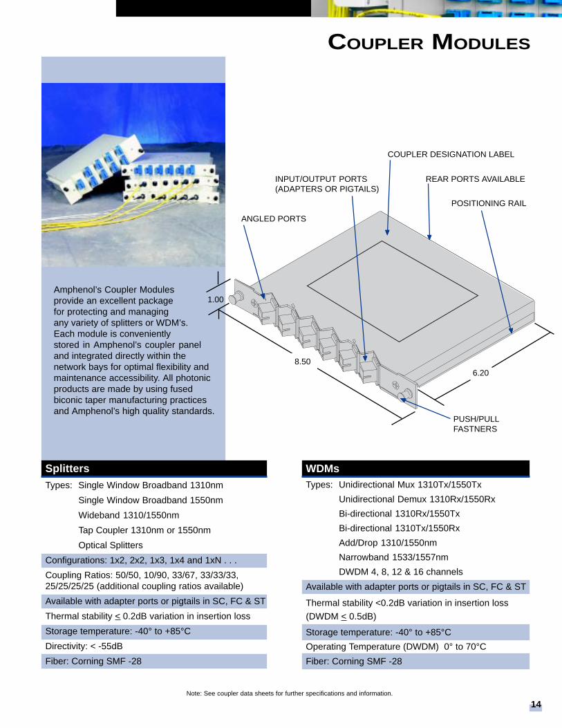
Amphenol’s Coupler Modulesprovide an excellent packagefor protecting and managingany variety of splitters or WDM’s.Each module is convenientlystored in Amphenol’s coupler paneland integrated directly within thenetwork bays for optimal flexibility andmaintenance accessibility. All photonicproducts are made by using fusedbiconic taper manufacturing practicesand Amphenol’s high quality standards.
REAR PORTS AVAILABLE
COUPLER DESIGNATION LABEL
POSITIONING RAIL
INPUT/OUTPUT PORTS(ADAPTERS OR PIGTAILS)
PUSH/PULLFASTNERS
ANGLED PORTS
6.208.50
1.00
WDMsTypes: Unidirectional Mux 1310Tx/1550Tx
Unidirectional Demux 1310Rx/1550Rx
Bi-directional 1310Rx/1550Tx
Bi-directional 1310Tx/1550Rx
Add/Drop 1310/1550nm
Narrowband 1533/1557nm
DWDM 4, 8, 12 & 16 channels
Available with adapter ports or pigtails in SC, FC & ST
Thermal stability <0.2dB variation in insertion loss
(DWDM < 0.5dB)
Storage temperature: -40° to +85°C
Operating Temperature (DWDM) 0° to 70°C
Fiber: Corning SMF -28
Note: See coupler data sheets for further specifications and information.
COUPLER MODULES
▲▲▲▲▲
▲▲▲▲▲
▲▲▲▲▲▲▲▲▲▲
▲▲▲▲▲▲▲▲▲▲
SplittersTypes: Single Window Broadband 1310nm
Single Window Broadband 1550nm
Wideband 1310/1550nm
Tap Coupler 1310nm or 1550nm
Optical Splitters
Configurations: 1x2, 2x2, 1x3, 1x4 and 1xN . . .
Coupling Ratios: 50/50, 10/90, 33/67, 33/33/33,25/25/25/25 (additional coupling ratios available)
Available with adapter ports or pigtails in SC, FC & ST
Thermal stability < 0.2dB variation in insertion loss
Storage temperature: -40° to +85°C
Directivity: < -55dB
Fiber: Corning SMF -28

16
CABLE ROUTING GUIDES
DescriptionComplete cable routing guide kits arecomposed of both Enhanced CableBrackets and Vertical Cable Guides. TheEnhanced Cable Brackets are designedto provide better cable managemententering and exiting enclosures. Theyallow fiber distribution frames to increasein fiber capacity by providing the abilityto add or remove patch cords withoutdisturbing neighboring fibers. TheVertical Cable Guides manage cablesrouted vertically alongside theenclosures.
Vertical Cable Guides• Provides an orderly channel for
routing fiber optic cables verticallyalong the enclosures.
• Versions available for 19” or 23”frames.
• Unique design allows panels tobe added or removed withoutremoving guides.
Enhanced Cable Brackets• Improved bend radius protection
allows fiber optic cables tomake a horizontalto vertical transition.
• Routing fingers provide excellentfiber organization by reducingthe number of fibers beinggrouped.
• Mounts directly to enclosure allowinggreater flexibility
Products
Part Number Description Where Used
948-100-5225 Vertical Cable Guides, 19” On 19” frames for all rack mount panels
948-100-5220 Vertical Cable Guides, 23” On 23” frames for all rack mount panels
948-100-5221 6” Enhanced Cable Guides 48 & 72 port rack mount panels
948-100-5222 9” Enhanced Cable Guides 96 port rack mount panels
948-100-5226* 6” Cable Routing Kit, 19” 19” frames and 48 & 72 port panels
948-100-5227* 9” Cable Routing Kit, 19” 19” frames and 96 port panels
948-100-5223* 6” Cable Routing Kit, 23” 23” frames and 48 & 72 port panels
948-100-5224* 9” Cable Routing Kit, 23” 23” frames and 96 port panels
CABLE ROUTING KIT
ENHANCED CABLE BRACKETS
* Cable Routing Kits include Verticle Cable Guides and Enhanced Cable Guides
CABLE CLAMP
DescriptionAmphenol’s Cable Clamp provides aunique method for securing fiber opticcables. Each cable clamp includes amulti-diameter module that perfectly fitsany size cable in its range.
The multi-diameter modules easily adaptto fit fiber optic cables simply byremoving a few layers from its centercore. This unique method of securing thecable provides excellent protection andaxial clamping.
Features• Unique multi-diameter module gently
grips cable without potential fordamage
• Accommodates a wide range ofcable sizes
• Removable layers allows a perfect fitto be easily made with the cable
• Three different sizes available to fitcables from 4 to 32 mm
• Configurations available for clampingmultiple cables within a single clamp
• Versions available for panel or framemounting
• Reduces radii required for enteringenclosures
Products
948SERIES
Part Number Description Where Used
948-100-5210 Cable Clamp 4-13.5mm Panel Mount
948-100-5211 Cable Clamp 12-22mm Panel Mount
948-100-5212 Cable Clamp 22-32mm Panel Mount
948-100-5213 Cable Clamp 4-13.5mm Frame Mount
948-100-5214 Cable Clamp 12-22mm Frame Mount
948-100-5215 Cable Clamp 22-32mm Frame Mount

STAND-OFF TO PREVENTCABLE DAMAGE
SPLICE TRAYS
18
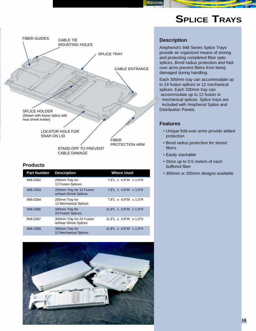
DescriptionAmphenol’s 948 Series Splice Traysprovide an organized means of storingand protecting completed fiber opticsplices. Bend radius protection and fold-over arms prevent fibers from beingdamaged during handling.
Each 300mm tray can accommodate upto 24 fusion splices or 12 mechanicalsplices. Each 200mm tray canaccommodate up to 12 fusion ormechanical splices. Splice trays areincluded with Amphenol Splice and
Distribution Panels.
Features• Unique fold-over arms provide added
protection
• Bend radius protection for storedfibers
• Easily stackable
• Store up to 0.5 meters of eachbuffered fiber
• 300mm or 200mm designs available
Products
SPLICE TRAY
CABLE ENTRANCE
FIBERPROTECTION ARM
CABLE TIEMOUNTING HOLES
FIBER GUIDES
SPLICE HOLDER(Shown with fusion splice withheat shrink holder)
Part Number Description Where Used
948-2362 200mm Tray for 7.8”L x 4.8”W x 1.0”H12 Fusion Splices
948-2363 200mm Tray for 12 Fusion 7.8”L x 4.8”W x 1.0”Hw/Heat Shrink Splices
948-2364 200mm Tray for 7.8”L x 4.8”W x 1.0”H12 Mechanical Splices
948-2366 300mm Tray for 11.8”L x 4.8”W x 1.0”H24 Fusion Splices
948-2367 300mm Tray for 24 Fusion 11.8”L x 4.8”W x 1.0”Hw/Heat Shrink Splices
948-2368 300mm Tray for 11.8”L x 4.8”W x 1.0”H12 Mechanical Splices
LOCATOR HOLE FORSNAP-ON LID
▲▲▲▲▲
▲▲▲▲▲
▲▲▲▲▲
▲▲▲▲▲
▲▲▲▲▲
▲▲▲▲▲
▲▲▲▲▲
▲▲▲▲▲

Six Pack Coupler ModulesAmphenol’s Six Pack Coupler Modulesare designed to incorporate splitters,WDMs, and tap couplers within a fiberoptic patch panel. The modules arecompletely enclosed giving optimalprotection to the fiber optic couplers.Six Pack Coupler Modules areavailable in a variety of configurations.Please contact the Inside SalesDepartment for more details.
Cable AssembliesAmphenol provides a complete array offiber optic patch cords and pigtails.Pigtails can be ordered pre-installedinto the fiber management panels toreduce installation time and costs. AllAmphenol patch cords and pigtails aremanufactured of the highest qualitymaterials and are 100% optically testedfor insertion loss and back reflection.
Six PacksAmphenol’s 948 Series Six Packs areincluded with Amphenol fibermanagement panels. Additional SixPacks are available as outlined below.They are available with all variations ofSC, FC, and ST adapters. Each sixpack comes loaded with the designatedadapter and nylatches for installation inAmphenol fiber management panels.
Six Packs (with Adapters)
PANEL ACCESSORIES948SERIES
Part Number Description Sleeve Type
948-100-2111 S/M SC Ceramic948-100-2112 S/M FC Flange Ceramic948-100-2113 S/M FC D-Hole Ceramic948-100-2114 S/M ST metal Ceramic948-100-2115 S/M SC Duplex Ceramic948-100-2116 S/M FC D-Hole, angle Ceramic948-100-2127 M/M SC Metal948-100-2122 M/M FC Flange Metal948-100-2123 M/M FC D-Hole Metal948-100-2124 M/M ST metal Metal948-100-2128 M/M SC Duplex Metal948-100-2110 Blank Cover n/a
Network Bays (Frames)A full line of unequal flange network baysare available with either 19” or 23”mounting configurations. Bays can be pre-loaded with any variety of fibermanagement panels to suit a broad rangeof customer requirements andapplications.
• Sturdy 11 gauge steel constructionwith a beige powder coat finish
• 12-24 tapped holes with 1” verticalspacing
• Designed to meet telephone industrystandards for Network Bay Framesand for Zone 4 Earthquake BracedBays
• Ground wire kit included with eachframe
20
DescriptionAmphenol’s 948 Series Frames andAccessories are designed to provide thenecessary organization and protectionrequired for fiber optic installations. Fiberprotection and integrity has beenconsidered throughout the FiberManagement System to insure that thereis ample bend radii and cable routing.
Ordering Information
FRAMES AND ACCESSORIES
Products• Network Bays • Cable Troughs
• End Panels • Rear Bay Doors
• Cable Brackets • Installation Kits
• Interbays • Cable Clamps
• Vertical Routing Guides
END PANEL
UPPER CABLETROUGH
NETWORK BAY
INTERBAY CABLEMANAGEMENT PANEL
LOWER CABLE TROUGH
41.3”
84.0”
Part No. Description Dimensions
948-2380 7’ x 23” Network Bay, seismic zone 4 84.0”H x 26.0”W x 12”D
948-2381 7’ x 19” Network Bay, seismic zone 4 84.0”H x 21.9”W x 12”D
948-2404 Rear Bay Doors 83.9”H x 26.0”W x 4.5”D
948-2447 Anchor Kit, Non-Isolated, seismic zone 4 n/a
948-2448 Anchor Kit, Isolated, seismic zone 4 n/a
▲▲▲▲▲
▲▲▲▲▲▲▲▲▲▲
▲▲▲▲▲
▲▲▲▲▲
NOTE: 7’x23” network Bay shown with accessories

UPPER and LOWER TROUGHS
FRAMES AND ACCESSORIES
Products
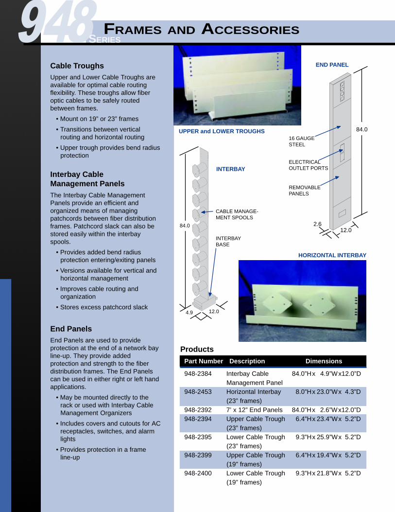
Cable TroughsUpper and Lower Cable Troughs areavailable for optimal cable routingflexibility. These troughs allow fiberoptic cables to be safely routedbetween frames.
• Mount on 19” or 23” frames
• Transitions between verticalrouting and horizontal routing
• Upper trough provides bend radiusprotection
Interbay CableManagement PanelsThe Interbay Cable ManagementPanels provide an efficient andorganized means of managingpatchcords between fiber distributionframes. Patchcord slack can also bestored easily within the interbayspools.
• Provides added bend radiusprotection entering/exiting panels
• Versions available for vertical andhorizontal management
• Improves cable routing andorganization
• Stores excess patchcord slack
End PanelsEnd Panels are used to provideprotection at the end of a network bayline-up. They provide addedprotection and strength to the fiberdistribution frames. The End Panelscan be used in either right or left handapplications.
• May be mounted directly to therack or used with Interbay CableManagement Organizers
• Includes covers and cutouts for ACreceptacles, switches, and alarmlights
• Provides protection in a frameline-up
948SERIES
Part Number Description Dimensions
948-2384 Interbay Cable 84.0”Hx 4.9”Wx12.0”DManagement Panel
948-2453 Horizontal Interbay 8.0”Hx 23.0”Wx 4.3”D(23” frames)
948-2392 7’ x 12” End Panels 84.0”Hx 2.6”Wx12.0”D948-2394 Upper Cable Trough 6.4”Hx 23.4”Wx 5.2”D
(23” frames)948-2395 Lower Cable Trough 9.3”Hx 25.9”Wx 5.2”D
(23” frames)948-2399 Upper Cable Trough 6.4”Hx 19.4”Wx 5.2”D
(19” frames)948-2400 Lower Cable Trough 9.3”Hx 21.8”Wx 5.2”D
(19” frames)
HORIZONTAL INTERBAY
84.0
12.02.6
16 GAUGESTEEL
ELECTRICALOUTLET PORTS
REMOVABLEPANELS
END PANEL
INTERBAY
84.0
CABLE MANAGE-MENT SPOOLS
INTERBAYBASE
12.04.9
▲▲▲▲▲
▲▲▲▲▲
▲▲▲▲▲▲▲▲▲▲
▲▲▲▲▲

Amphenol Corporation Websitewww.amphenol.com
Worldwide Service & Support
Fiber Optic Productswww.amphenol-fiberoptics.comsales@amphenol-fiberoptics.com1-800-944-6446
AMERICAS
Amphenol CorporationWallingford, CT, U.S.A.Phone: +1-203-265-8900E-mail: [email protected]
Amphenol Canada Corp.Scarborough, Ontario, CanadaPhone: +1-416-291-4401E-mail: [email protected]
Amphenol Interconnect ProductsCorporationEndicott, NY, U.S.A.Phone: +1-607-754-4444E-mail: [email protected]
Amphenol Spectra-Strip OperationsHamden, CT, U.S.A.Phone: +1-203-281-3200Email: [email protected]
Amphenol RF DivisionDanbury, CT., U.S.A.Phone: 1-203-796-2000E-mail: [email protected]
Amphenol do Brasil LTDA (AIPC)Cacapava, SP, BrazilPhone: +55-12-253-2502E-mail: [email protected]
Amphenol Corp. ArgentinaBuenos Aires, ArgentinaPhone: +54-11-4341-4565 E-mail: [email protected]
Amphenol do Brasil LTDA.Sao Paulo - SP, BrazilPhone: +55-11-5185-2881E-mail: [email protected]
Amphenol Corp. MexicoCP 11560 Mexico D.F. MexicoPhone:+52-5-254-7283E-mail:[email protected]
Times Fiber Communications, Inc.Wallingford, CT, U.S.A.Phone: 1-203-265-8500E-mail: [email protected]
EUROPE
Amphenol European Sales OperationsHouten, The NetherlandsPhone: +31-30-6358-000E-mail: [email protected]
Amphenol Gessellscaft GmbHWien, AustriaPhone: +43-1-895-1511E-mail: [email protected]
Amphenol IbericaMadrid, SpainPhone: +34-91-673-2235E-mail: [email protected]
Amphenol Italia S.p.A.Lainate (Milano), ItalyPhone: +39-2-939-04192Email: [email protected]
Amphenol ScandinaviaUpplands Vasby, SwedenPhone: +46-8-594-10040E-mail: [email protected]
Amphenol LimitedWhitstable, Kent, Great BritainPhone: +44-227-773-200E-mail: [email protected]
Amphenol Socapex 948, Promenade de l’ArveB.P. 2974311 Thyez, Cedex, FrancePhone: +33-4-50-89-28-00E-mail: [email protected]
Amphenol Air LB GmbHAM Kleinbahnhof 4D-66740 SaarlouisGermanyPhone: +49-6831-981-00E-mail: [email protected]
ASIA & R.O.W.
Amphenol Japan. K.K.Chiyoda-ku, Tokyo, JapanPhone: +81-3-3263-5611E-mail: [email protected]
Amphenol Daeshin ElectronicsPrecision Co., Ltd.Kyungki-Do, KoreaPhone: +82-32-680-3800E-mail: [email protected]
Amphenol East Asia Ltd.Kowloon, Hong KongPhone: +852-2699-2663E-mail: [email protected]
Amphenol Taiwan Corp.Taoyuan, TaiwanPhone: +886-3-379-5677E-mail: [email protected]
Amphenol South ChinaBao An, Shenzhen, ChinaPhone: +86-755-719-9622E-mail: [email protected]
Shenzhen (China) OfficeShenzhen, ChinaPhone: +86-755-368-3575E-mail: [email protected]
Guangzhou Amphenol Electronics CommunicationsGuangzhou, ChinaPhone: +86-20-3869-8808E-mail: [email protected]
Singapore OfficePhone: +65-294-2128E-mail: [email protected]
Amphetronix LimitedBhosari Industrial AreaPune, IndiaPhone: +91-20-7120363E-mail: [email protected]
Amphenol Australia Ltd.Keysborough Vic, AustraliaPhone: +61-3-8796-8888E-mail: [email protected]