Series A 3 - A 32
7
12 1 Series A 3 connectors are available both with screw and IDC terminals. Series A 4 connectors, how- ever, are only available with screw terminals. Series A 5 is equipped with crimp contacts of series B for 16 A. The use of a coding pin prevents incorrect mating of connectors. If necessary, the engaged crimp contacts can be released by means of a special removal tool. This applies also for the series A 10, A 16 and A 32, which are additionally available with screw contact carriers. Screw terminal inserts are equipped with a wire protec- tion. This wire protection saves the time-consuming crimping of wire-end ferrules. Of course, all WALTHER contacts are provided with open, captive screws. Housings of series A 3 to A 16 are provided with a single locking lever. Housings of series A 32 have two locking levers. Snap-on mounting adapters are ideal for mounting into switch cabinets. The convenience of IDC con- nection is now also available with a classic square connec- tor – a 4-pole (3+PE) industrial plug connector of series A. Male and female versions are available in hoods and coupler hoods made of plastic. Thanks to insulation dis- placement connection, it now only takes a few seconds to connect the 4-pole round conductor: Only the sleeve nut has to be slid over the conduc- tor – since splicing ring, seal and strain relief are included in the sleeve nut. Series A 3 - A 32 Series A 3 housings are avail- able either in plastic or zinc die-casting - according to your requirements. the switch cabinet, which then ena- bles the instal- lation of printed circuit boards. Mounting is made by snap- ping connectors onto DIN-rails in transverse direction. When installing several mounting plates side-by side, an additional cable duct can be built up inside The clearly arranged swing-type insertion plate allows easy wiring.
Transcript of Series A 3 - A 32

12
1
Series A 3 connectors are available both with screw and IDC terminals.
Series A 4 connectors, how-ever, are only available with screw terminals.
Series A 5 is equipped with crimp contacts of series B for 16 A. The use of a coding pin prevents incorrect mating of connectors.
If necessary, the engaged crimp
contacts can
be releasedby means of a special removal tool.
This applies also for the series A 10, A 16 and A 32, which are additionally available with screw contact carriers.
Screw terminal inserts are equipped with a wire protec-tion. This wire protection saves the time-consuming crimping of wire-end ferrules.
Of course, all WALTHER contacts are provided with open, captive screws.
Housings of series A 3 to A 16 are provided with a single locking lever. Housings of series A 32 have two locking levers.
Snap-on mounting adapters are ideal for mounting into switch cabinets.
The convenience of IDC con-nection is now also available with a classic square connec-tor – a 4-pole (3+PE) industrial plug connector of series A.
Male and female versions are available in hoods and coupler hoods made of plastic.
Thanks to insulation dis-placement connection, it now only takes a few seconds to connect the 4-pole round conductor: Only the sleeve nut has to be slid over the conduc-tor – since splicing ring, seal and strain relief are included in the sleeve nut.
Series A 3 - A 32
Series A 3 housings are avail-able either in plastic or zinc die-casting - according to your requirements.
the switch cabinet, which then ena-bles the instal-lation of printed circuit boards.
Mounting is made by snap-
ping connectors onto DIN-rails in transverse direction.
the switch cabinet, which then ena-bles the instal-lation of printed circuit boards.
Mounting is
When installing several mounting plates side-by side, an additional cable duct can be built up inside
If necessary, the engaged crimp
contacts can
be releasedby means of a special removal tool
The clearly arranged swing-type insertion plate allows easy wiring.

Series A
13
1
Serie A3 / A4
0
5
10
15
20
25
30
35
10 20 30 40 50 60 70 80 90 100 110 120 130Umgebungstemperatur
Be
trie
bss
tro
m
2.5mm²1.5mm²1.0mm²
2 .5 m m ² 1 .5 m m ² 1 .0 m m ²
Regulations: DIN VDE 0627, DIN VDE 0110, DIN EN 61 984
Approvals: UR, CSA, MEIE, EZÚ
Number of poles: 3, 4, 5, 10, 16, 32 (2 x 16) + PE
Electrical Data acc. to DIN EN 61 984:
Series A3/A4 10 A 230 / 400 V 4 kV 3
Rated currentRated voltage conductor - earthRated voltage conductor - conductorRated surgePollution degreeor 10 A 250 V 4 kV 3
Series A5 16 A 230 / 400 V 4 kV 3
Rated currentRated voltage conductor - earthRated voltage conductor - conductorRated surgePollution degree
- Pollution degree 2 also 16 A 320/500 V 4 kV 2
Series A 10 / A 16 16 A 250 V 4 kV 3
Rated current Rated voltageRated surgePollution degreePollution degree 2 also 16 A 230 / 400 V 4 kV 2
Rated voltage acc. to UL/CSA: 600 V(Table with rated surges see chapter ”Information”)
Material: Glass-fi bre reinforced polyamideTemperature range: - 40 °C up to + 125 °CFlame class rating acc. to UL 94: V 0Mechanical operating life: > 500 mating cycles
Contacts
Material: copper alloySurface • hard silver plated: 3 µm Ag • hard gold plated: 2 µm Au over 3 µm Ni Contact resistance: < 1 m Ω
Series A 10 / A 16:Crimp type terminal mm² (AWG): 0.14 - 4.0 mm² (26-12 AWG)Screw type terminal mm² (AWG): 0.5 - 2.5 mm² (14 AWG)
Series A 3 / A 4:only screw type mm² (AWG): 0.5 - 1.5 mm² (16 AWG)Torque/testing torque: A 3 and A 4: 0.25 Nm A 10 and A 16: 0.5 Nm Series A 5:only crimp terminal mm² (AWG): 0.14 - 2.5 mm² (26-14 AWG)
Wire stripping length:
Series A 3 and A 4: 5 mmSeries A 5, A 10 and A 16: 7 mm with screw and crimping contacts
Application hint: Industrial connectors are electrical devices which must not be connected or disconnected under load!
A 32-pole +
Inserts 18
- Short overview see page 102 -- Matching housings see page 103 - 105 -
A 10-pole +
Inserts 16
- Short overview see page 94 -- Matching housings see page 95 - 96 -
A 4-pole +
Inserts 15
- Short overview see page 90 -- Matching housings see page 91 - 92 -
A 3-pole +
Inserts 14
- Short overview see page 90 -- Matching housings see page 91 - 92 -
A 16-pole +
Inserts 17
- Short overview see page 98 -- Matching housings see page 99 - 100 -
Specifi cations Page
The derating diagram (corrected current capacity curve) acc. to DIN IEC 60 512 applies to such current which can - depending on
ambient temperature and conduc-tor size - circulate through each contact without exceeding the upper limiting temperature.
A 5-pole +
Inserts 15
- Short overview see page 90 -- Matching housings see page 91 - 92 -
Serie A3 / A4
0
5
10
15
20
25
30
35
10 20 30 40 50 60 70 80 90 100 110 120 130Umgebungstemperatur
Be
trie
bss
tro
m
2.5mm²1.5mm²1.0mm²
2 .5 m m ² 1 .5 m m ² 1 .0 m m ²
Series A3 / A4
0
5
10
15
20
25
30
35
10 20 30 40 50 60 70 80 90 100 110 120 130Ambient temperature
Op
era
tin
g c
urr
en
t
2.5mm²1.5mm²1.0mm²
2 .5 m m ² 1 .5 m m ² 1 .0 m m ²
Series A3 / A4
Serie A 5
0
5
10
15
20
25
30
35
10 20 30 40 50 60 70 80 90 100 110 120 130
2.5mm²1.5mm²
Umgebungstemperatur
Be
trie
bss
tro
m
Series A 5
0
5
10
15
20
25
30
35
10 20 30 40 50 60 70 80 90 100 110 120 130
2.5mm²1.5mm²
Ambient temperature
Op
era
tin
g c
urr
en
t Series A5
Serie A 10
0
5
10
15
20
25
30
35
10 20 30 40 50 60 70 80 90 100 110 120 130
2.5mm²1.5mm²1.0mm²
Umgebungstemperatur
Be
trie
bss
tro
m
Series A 10
0
5
10
15
20
25
30
35
10 20 30 40 50 60 70 80 90 100 110 120 130
2.5mm²1.5mm²1.0mm²
Ambient temperature
Op
era
tin
g c
urr
en
t Series A 10
Serie A 16
0
5
10
15
20
25
30
35
10 20 30 40 50 60 70 80 90 100 110 120 130
2.5mm²1.5mm²1.0mm²
Umgebungstemperatur
Be
trie
bss
tro
m
Series A 16
0
5
10
15
20
25
30
35
10 20 30 40 50 60 70 80 90 100 110 120 130
2.5mm²1.5mm²1.0mm²
Ambient temperature
Op
era
tin
g c
urr
en
t Series A16

Description Part no.
14
1
Series A 3 P + 10 A / 230/400 V UL/CSA: 600 V g
Screw terminal inserts
Female insertScrew terminal
without wire protection0.5-1.5 mm² (20-16 AWG)
700 1031014
1014
Male insertScrew terminal
without wire protection0.5-1.5 mm² (20-16 AWG)
700 203
Contact arrangement View from termination side
Maleinsert
Femaleinsert
Matching housings for screw terminal inserts see page 91 - 92
Connectors with insulationdisplacement connection (IDC)
Hood with female insertHeight 66 mmfor single locking system
Hood with male insertHeight 66 mmfor single locking system
Coupler hood with female insertHeight 63 mmwith single locking system
Coupler hood with male insertHeight 63 mmwith single locking system
1025
1025
1028
1028
Specifi cations of connectors with insulation displacement connection:
General:Key width of sleeve nut 19 mmTorque of sleeve nut 3 NmMating cycles < 500
Cable specifi cations for IDC connection:
Conductor cross section area: 0.75 - 1.5 mm² / 18 -16 AWGStranded cable / smallest wire diameter: VDE 0295 class 2 up to 5/0.2 mmCore insulating material: PVC/PEExternal cable diameter: 6 - 12 mmWire diameter (incl. insulation) ≤ 3
Mechanical specifi cations:Frequency of connection of cables with equal diameter: 10
Material:Contact material / contact surface: Copper alloy/nickel base coat, silver-platedInsulating material / fl ammability acc. to UL 94: PA / V0Approvals: UL/CSA
700 724
700 725
700 726
700 727
1
3 2
1
2 3
Description Part no.
15
1
Description Part no.
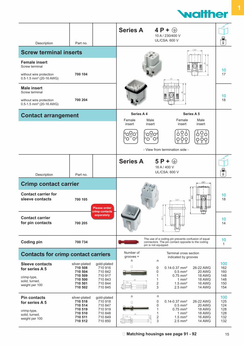
Series A 4 P + 10 A / 230/400 V UL/CSA: 600 V
Series A 5 P + 16 A / 400 V
UL/CSA: 600 V
g
g
Screw terminal inserts
Female insertScrew terminal
without wire protection0.5-1.5 mm² (20-16 AWG)
700 1041017
1018
Male insertScrew terminal
without wire protection0.5-1.5 mm² (20-16 AWG)
700 204
Contact arrangement
- View from termination side -
Maleinsert
Femaleinsert
Matching housings see page 91 - 92
Maleinsert
Series A 4 Series A 5
Crimp contact carrier
Contact carrier for sleeve contacts
Contact carrier for pin contacts
700 105
700 205
1018
1014
101
Femaleinsert
Contacts for crimp contact carriers
Sleeve contactsfor series A 5
crimp-type,solid, turned,weight per 100
silver-plated710 508710 504710 509710 500710 501710 502
Pin contactsfor series A 5
crimp-type,solid, turned,weight per 100
silver-plated710 518710 514710 519710 510710 511710 512
0.14-0.37 mm²0.5 mm²
0.75 mm²1 mm²
1.5 mm²2.5 mm²
26-22 AWG
20 AWG18 AWG18 AWG16 AWG14 AWG
0.14-0.37 mm²0.5 mm²
0.75 mm²1 mm²
1.5 mm²2.5 mm²
26-22 AWG
20 AWG18 AWG18 AWG16 AWG14 AWG
gold-plated710 916710 842710 917710 843710 844710 845
gold-plated710 918710 847710 919710 848710 849710 850
001123
001123
100162160148148150154
100125124128128132132
Terminal cross sectionindicated by grooves
n
Number of grooves =
n
n
Coding pin 700 734The use of a coding pin prevents confusion of equal connectors. The pin contact opposite to the coding pin is not equipped.
n
Please order crimp contacts
separately
4 1
3 2
21
3 4 5
1 4
2 3
12
5 4 3

16
1
Description Part no.
Series A 10 P + 16 A / 250 V
UL/CSA: 600 V g
Screw terminal inserts
Female insertScrew terminal
with wire protection 0.5-2.5 mm² (20-14 AWG)
700 110
Crimp contact carrier
Contact carrierfor sleeve contacts
Contact carrierfor pin contacts
1046
1047
1026
1027
Male insertScrew terminal
with wire protection 0.5-2.5 mm² (20-14 AWG)
700 210
Contact arrangementView from termination sidePanel cut-out
Male insertFemale insert
700 310
700 410
Contacts for crimp contact carriers
Sleeve contactsfor series A 10
crimp-type,solid, turned,weight per 100
silver-plated710 508710 504710 509710 500710 501710 502710 503
Pin contactsfor series A 10
crimp-type,solid, turned,weight per 100
silver-plated710 518710 514710 519710 510710 511710 512710 513
gold-plated710 916710 842710 917710 843710 844710 845710 846
gold-plated710 918710 847710 919710 848710 849710 850710 851
100162160148148150154165
100125124128128132132134
Sleeve contactOptical waveguide for POF,solid, turned
710 52110089
Pin contactOptical waveguide for POF,solid, turned
10074710 531
Weight per 100
Weight per 100
101Coding pin 700 734
The use of a coding pin prevents confusion of equal connectors. The pin contact opposite to the coding pin is not equipped.
0.14-0.37 mm²0.5 mm²
0.75 mm²1 mm²
1.5 mm²2.5 mm²4.0 mm²
26-22 AWG
20 AWG18 AWG18 AWG16 AWG14 AWG12 AWG
0.14-0.37 mm²0.5 mm²
0.75 mm²1 mm²
1.5 mm²2.5 mm²4.0 mm²
26-22 AWG
20 AWG18 AWG18 AWG16 AWG14 AWG12 AWG
0011230
n0011230
n
Number of grooves =
n
n
POF* Ø 1 mm
POF* Ø 1 mm
Terminal cross sectionindicated by grooves
Matching housings see page 95 - 96
Please order crimp contacts
separately
Crimping area
Crimping area
1 6
2 7
3 8
4 9
5 10
6 1
7 2
8 3
9 4
10 5

17
1
Description Part no.
Series A 16 P + 16 A / 250 V
UL/CSA: 600 V g
Screw terminal inserts
Female insertScrew terminal
with wire protection 0.5-2.5 mm² (20-14 AWG)
700 116
Crimp contact carrier
Contact carrierfor sleeve contacts 700 316
Contact carrierfor pin contacts 700 416
1065
1063
1032
1031
Male insertScrew terminal
with wire protection 0.5-2.5 mm² (20-14 AWG)
700 216
Contact arrangementView from termination sidePanel cut-out
Male insertFemale insert
9 1
10 2
11 3
12 4
13 5
14 6
15 7
16 8
1 9
2 10
3 11
4 12
5 13
6 14
7 15
8 16
Contacts for crimp contact carriers
Sleeve contactsfor series A 16
crimp-type,solid, turned,weight per 100
silver-plated710 508710 504710 509710 500710 501710 502710 503
Pin contactsfor series A 16
crimp-type,solid, turned,weight per 100
silver-plated710 518710 514710 519710 510710 511710 512710 513
gold-plated710 916710 842710 917710 843710 844710 845710 846
gold-plated710 918710 847710 919710 848710 849710 850710 851
100162160148148150154165
100125124128128132132134
Sleeve contactOptical waveguide for POF,solid, turned
710 52110089
Pin contactOptical waveguide for POF,solid, turned
10074710 531
Weight per 100
Weight per 100
101Coding pin 700 734
The use of a coding pin prevents confusion of equal connectors. The pin contact opposite to the coding pin is not equipped.
0.14-0.37 mm²0.5 mm²
0.75 mm²1 mm²
1.5 mm²2.5 mm²4.0 mm²
26-22 AWG
20 AWG18 AWG18 AWG16 AWG14 AWG12 AWG
0.14-0.37 mm²0.5 mm²
0.75 mm²1 mm²
1.5 mm²2.5 mm²4.0 mm²
26-22 AWG
20 AWG18 AWG18 AWG16 AWG14 AWG12 AWG
0011230
n0011230
n
Number of grooves =
n
n
POF* Ø 1 mm
POF* Ø 1 mm
Terminal cross sectionindicated by grooves
Matching housings see page 99 - 100
Please order crimp contacts
separately
Crimping area
Crimping area

18
1
Description Part no.
Series A 32 P + 16 A / 250 V
UL/CSA: 600 V g
Female insertScrew terminal,0.5-2.5 mm² (20-14 AWG)
with wire protection 1 - 16
with wire protection 17 - 32
700 116
700 132
Crimp contact carrier
Contact carriers
for sleeve contacts 1 - 16for sleeve contacts 17 - 32
700 316700 332
Contact carriers
for pin contacts 1 - 16for pin contacts 17 - 32
700 416700 432
1069
69
103838
103636
Male insertScrew terminal,0.5-2.5 mm² (20-14 AWG)
with wire protection 1 - 16
with wire protection 17 - 32
700 216
700 232
1064
64
Screw terminal inserts
Contact arrangementView from termination sidePanel cut-out
Male insertFemale insert
1 9
2 10
3 11
4 12
5 13
6 14
7 15
8 16
17 25
18 26
19 27
20 28
21 29
22 30
23 31
24 32
Matching housings see page 103 - 105
Please order crimp contacts
separately
Contacts for crimp contact carriers
Sleeve contactsfor series A 10
crimp-type,solid, turned,weight per 100
silver-plated710 508710 504710 509710 500710 501710 502710 503
Pin contactsfor series A 10
crimp-type,solid, turned,weight per 100
silver-plated710 518710 514710 519710 510710 511710 512710 513
gold-plated710 916710 842710 917710 843710 844710 845710 846
gold-plated710 918710 847710 919710 848710 849710 850710 851
100162160148148150154165
100125124128128132132134
Sleeve contactOptical waveguide for POF,solid, turned
710 52110089
Pin contactOptical waveguide for POF,solid, turned
10074710 531
Weight per 100
Weight per 100
101Coding pin 700 734
The use of a coding pin prevents confusion of equal connectors. The pin contact opposite to the coding pin is not equipped.
0.14-0.37 mm²0.5 mm²
0.75 mm²1 mm²
1.5 mm²2.5 mm²4.0 mm²
26-22 AWG
20 AWG18 AWG18 AWG16 AWG14 AWG12 AWG
0.14-0.37 mm²0.5 mm²
0.75 mm²1 mm²
1.5 mm²2.5 mm²4.0 mm²
26-22 AWG
20 AWG18 AWG18 AWG16 AWG14 AWG12 AWG
0011230
n0011230
n
Number of grooves =
n
n
POF* Ø 1 mm
POF* Ø 1 mm
Terminal cross sectionindicated by grooves
25 17
26 18
27 19
28 20
29 21
30 22
31 23
32 24
9 1
10 2
11 3
12 4
13 5
14 6
15 7
16 8
Crimping area
Crimping area