Series 67 and 767 Low Water Cut-Offs For Steam Boilers
12
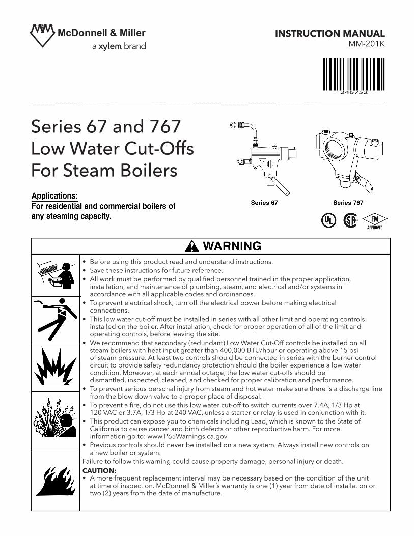
INSTRUCTION MANUAL MM-201K Series 67 and 767 Low Water Cut-Offs For Steam Boilers 246752 • Before using this product read and understand instructions. • Save these instructions for future reference. • All work must be performed by qualified personnel trained in the proper application, installation, and maintenance of plumbing, steam, and electrical and/or systems in accordance with all applicable codes and ordinances. • To prevent electrical shock, turn off the electrical power before making electrical connections. • This low water cut-off must be installed in series with all other limit and operating controls installed on the boiler. After installation, check for proper operation of all of the limit and operating controls, before leaving the site. • We recommend that secondary (redundant) Low Water Cut-Off controls be installed on all steam boilers with heat input greater than 400,000 BTU/hour or operating above 15 psi of steam pressure. At least two controls should be connected in series with the burner control circuit to provide safety redundancy protection should the boiler experience a low water condition. Moreover, at each annual outage, the low water cut-offs should be dismantled, inspected, cleaned, and checked for proper calibration and performance. • To prevent serious personal injury from steam and hot water make sure there is a discharge line from the blow down valve to a proper place of disposal. • To prevent a fire, do not use this low water cut-off to switch currents over 7.4A, 1/3 Hp at 120 VAC or 3.7A, 1/3 Hp at 240 VAC, unless a starter or relay is used in conjunction with it. • This product can expose you to chemicals including Lead, which is known to the State of California to cause cancer and birth defects or other reproductive harm. For more information go to: www.P65Warnings.ca.gov. • Previous controls should never be installed on a new system. Always install new controls on a new boiler or system. Failure to follow this warning could cause property damage, personal injury or death. CAUTION: • A more frequent replacement interval may be necessary based on the condition of the unit at time of inspection. McDonnell & Miller’s warranty is one (1) year from date of installation or two (2) years from the date of manufacture.
Transcript of Series 67 and 767 Low Water Cut-Offs For Steam Boilers
INSTRUCTION MANUAL MM-201K
Series 67 and 767Low Water Cut-OffsFor Steam Boilers
246752
• Before using this product read and understand instructions.• Save these instructions for future reference.• Allworkmustbeperformedbyqualifiedpersonneltrainedintheproperapplication, installation,andmaintenanceofplumbing,steam,andelectricaland/orsystemsin accordance with all applicable codes and ordinances. • Topreventelectricalshock,turnofftheelectricalpowerbeforemakingelectrical connections.• This low water cut-off must be installed in series with all other limit and operating controls installedontheboiler.Afterinstallation,checkforproperoperationofallofthelimitand operatingcontrols,beforeleavingthesite.• We recommend that secondary (redundant) Low Water Cut-Off controls be installed on all steamboilerswithheatinputgreaterthan400,000BTU/houroroperatingabove15psi of steam pressure. At least two controls should be connected in series with the burner control circuit to provide safety redundancy protection should the boiler experience a low water condition.Moreover,ateachannualoutage,thelowwatercut-offsshouldbe dismantled,inspected,cleaned,andcheckedforpropercalibrationandperformance.• To prevent serious personal injury from steam and hot water make sure there is a discharge line from the blow down valve to a proper place of disposal.• Topreventafire,donotusethislowwatercut-offtoswitchcurrentsover7.4A,1/3Hpat 120VACor3.7A,1/3Hpat240VAC,unlessastarterorrelayisusedinconjunctionwithit.• ThisproductcanexposeyoutochemicalsincludingLead,whichisknowntotheStateof California to cause cancer and birth defects or other reproductive harm. For more informationgoto:www.P65Warnings.ca.gov.• Previous controls should never be installed on a new system. Always install new controls on a new boiler or system.Failuretofollowthiswarningcouldcausepropertydamage,personalinjuryordeath.CAUTION:• A more frequent replacement interval may be necessary based on the condition of the unit at time of inspection. McDonnell & Miller’s warranty is one (1) year from date of installation or two (2) years from the date of manufacture.

A
D
2
INSTALLATION –TOOLS NEEDED:One (1) tube cutter, one (1) pencil, one (1) flatheadscrewdriver, one (1) adjustable wrench and two (2)pipe wrenches.
The Series 67 and Series 767 low water cut-offs arefloat-type boiler controls designed to interrupt currentto the burner whenever the water drops to the cut-offlevel.
The Series 767 is identical to Series 67 in allrespects except one. The Series 767 is equipped with
a 2-1/2" (63.5mm) pipe tap opening in the body, anddoes not require the quick hook-up fittings suppliedwith the Series 67. The pipe tapping allows for adirect connection to the side of the boiler.
Electrical Ratings
Pump Circuit Rating (Amperes)Voltage Full Load Locked Rotor Pilot Duty
125 VA at120 or 240 VAC
For Series 67 - The elevation of the control (A)is already determined by the location of thegauge glass tappings (B,C) on the boiler. Thehorizontal cast line (D) should be located at orabove the boiler manufacturer's minimum safewater level (E).
For Series 767 - The elevation of the control (A)is already determined by the location of the 2-1/2 (63.5mm) pipe tapping on the boiler. Thehorizontal cast line (D) of the body (A) shouldbe located at or above the boiler manufacturer'sminimum safe water level.
STEP 1 - Determine the Elevation at Which theLow Water Cut-Off Controller Must be Installed
C A
E
BD
IMPORTANT: Follow the boiler manufacturer'sinstructions along with all applicable codes andordinances for piping, blow down valve and watergauge glass installation.
OPERATIONMaximum Steam Pressure: 20 psi (1.4 kg/cm2)
Series 67
Series 767
Note: 11 MV is rated at 24 VA @ 24 VAC to 120 VAC
120 VAC 7.4 44.4240 VAC 3.7 22.2

3
a. Turn the boiler off.
b. Drain the water in the boiler to a level whichis below the lower gauge glass tapping (B)of the control body (A). Allow the boiler tocool to 80˚F (27˚C) and allow the pressureto release to 0 psi (0 bar).
STEP 2 - Preparation
OFF
ON
AA
B
a. Using a pipe wrench, remove the float blockingtube (F) from the new control and tighten a 2"(13mm) NPT pipe plug (G) (provided) into thetapping on the bottom of the control body (A).Tighten the pipe plug to 31 ft•lb (42 N•m).
A
FG
When using the tape sealant on the external threads of pipes or fittings, follow the manufacturers instructions. Usesparingly and do not place on the first thread.
! CAUTION
STEP 3 - Installing the New Low Water Cut-Off
b. Using a pipe wrench, install a 2" (13mm)nipple (H) into the lower gauge glass tapping(B) and pipe tee assembly (J). Tighten bothconnections to 31 ft•lb (42 N•m).
J
B
H

c. Using an adjustable wrench, install a a"(9.5mm) NPT compression fitting base (K)to the upper tapping (L) in the control (A).Tighten to 31 ft•lb (42 N•m). A
LK
N
M
d. Using a pipe wrench, install a 2" (13mm)nipple (M) into the upper tapping (N).Tighten to 31 ft•lb (42 N•m).
e. Using a pipe wrench, install the pipe tee (P)(provided) onto the nipple (M) in the uppertapping (N). Tighten to 31 ft•lb (42 N•m).
N M
P
f. Using an adjustable wrench, install 1/2 (13mm) NPTcompression fitting base (U) into the upper tee (P).Tighten to 31 ft•lb (42 N•m). Place the compression nut(R) and compression ring (S) over the top of tubing (Q).Insert tubing (Q) into compression base (U). Turncompression nut (R) hand tight. DO NOT TIGHTEN.
IMPORTANT: Do not use tape or pipesealant on the compression fittings.
Q
U S R
P
4

h. Insert the tubing (Q) into the upper compres-sion fitting (U) and tighten the fitting to 31 ft•lb(42 N•m).
U
Q
g. Position the tubing (Q) next to the compressionfitting (K) and, using a pencil, mark the tubing(Q) for proper insertion into the compression fitting (K).
Remove the tubing (Q), and, using the tube cutter, cut the tubing to its proper length.
Q
K
5
i. Using two (2) pipe wrenches, rotate the uppertee (P) counterclockwise and the lower tee (J)clockwise.
j. Place the compression nut (R) and the compres-sion ring (S) over the bottom of the tubing (Q).
P
J
Q
SR

k. Using two (2) pipe wrenches, rotate the uppertee (P) clockwise and the lower tee (J) counter-clockwise so that the end of the tube can beinserted into the lower compression fitting (K).NOTE: Make sure that the control is in a hori-zontal position. Using an adjustable wrench,tighten the lower compression fitting (K) to 31 ft•lb (42 N•m).
K
J
P
6
T
U
V
l. Using a pipe wrench, install a w" (19mm) NPTpipe (T) into the opening of the blow downvalve (U) and tighten to 47 ft•lb (64 N•m).
A
W
m. Hang the blow down card (W) (enclosed) as close to the control (A) as possible, or remove the protective backing and affix the card on the boiler jacket close to the control.
X
a. Using a pipe wrench, install a 22" (63.5mm)nipple (X) into the side of the boiler. Tightento 109 ft•lb (148 N•m).
For Series 767
To prevent burning or scalding, pipe blow-offdischarge from blow-down valve to floor –allowing enough height for a pail under dis-charge pipe to collect blow down discharge.This pipe must be same 3/4” size as blow-down connection; do not reduce. Do notthread end of pipe.
! CAUTION

7
T
U
A
W
c. Using a pipe wrench, install a w" (19mm) NPTpipe (T) into the opening of the blow downvalve (U) and tighten to 47 ft•lb (64 N•m).
A
b. Install the control (A) by rotating it onto the 22"(63.5mm) nipple (X, as shown in Step a on previous page). Tighten to 109 ft•lb (148 N•m).
d. Hang a blow down card (W) (enclosed) asclose to the control (A) as possible, or removethe protective backing and affix the card onthe boiler jacket close to the control.
To prevent burning or scalding, pipe blow-offdischarge from blow-down valve to floor –allowing enough height for a pail under dis-charge pipe to collect blow down discharge.This pipe must be same 3/4” size as blow-down connection; do not reduce. Do notthread end of pipe.
! CAUTION

8
STEP 4 - Electrical Wiring
a. Using a flathead screwdriver, remove the one(1) screw that secures the low water cut-offswitch cover (Y).
• To prevent electrical shock, turn off the electrical power before making electrical connections.
• This low water cut-off must be installed in series with all other limit and operating controls installed on the boiler. After installation, check for proper operation of all of the limit and operating controls, before leaving the site.
Failure to follow this warning could cause electrical shock, an explosion and/or a fire, which could result inproperty damage, personal injury or death.
! WARNING
Y
b. Using a flathead screwdriver, loosen the two(2) screws and remove the feeder cover (Z).
Z
For 67 Low Water Cut-Off Installed with McDonnell & Miller Uni-Match Water-Feeder
c. Position the slide switch selector (AA) in the #1 position.
Directory: 67 Low Water Cut-Off and Uni-Match Water Feeder page 8 - 967 Low Water Cut-Off and 101 Water Feeder page 10 - 11
AA


NOTE: To connect wires to the terminalson the burner, or low water cut-off, placethe bare end of the wire under the terminalscrew and tighten the screw with a flat-head screwdriver. On the 101-A waterfeeder use wire nuts.
Ya. Using a flathead screwdriver, remove the one(1) screw that secures the low water cut-offsswitch housing (Y).
BB
b. Using a flathead screwdriver, remove the two(2) screws that secure the feeder cover (BB).
For 67 Low Water Cut-Off Installed with McDonnell & Miller Series 101-A Water-Feeder
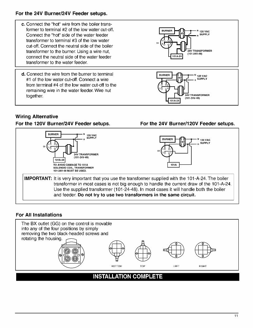
For the 120V Burner/120V Feeder setups.
BURNER
120 VACSUPPLY
1 2
3 4
N
H
101A
69
c. Using a wire nut, connect a wire from theneutral side of the power supply to one ofthe wires inside the feeders junction box.(Does not make a difference which one).Connect a wire from the "hot" side of thepower supply to terminal #2 of the Series 67junction box. Connect the neutral side of thepower supply to the burner.
BURNER
120 VACSUPPLY
1 2
3 4
N
H
101A
d. Connect the wire from the burner to terminal#1 of the low water cut-off. Connect a"jumper" from terminal #2 to terminal #3 of thelow water cut-off. Connect a wire from termi-nal #4 of the low water cut-off to the remain-ing wire in the 101A water feeder.
10

Xylem Inc.
8200 N. Austin Avenue Morton Grove, Illinois 60053 Phone: (847) 966-3700 Fax: (847) 965-8379www.xylem.com/mcdonnellmiller
McDonnell & Miller is a trademark of Xylem Inc. or one of its subsidiaries. © 2019 Xylem Inc. MM-201K March 2019 Part No. 246752
COMMERCIAL WARRANTYWarranty. For goods sold to commercial buyers, Seller warrants the goods sold to Buyer hereunder (with the exception of membranes, seals, gaskets, elastomer materials, coatings and other “wear parts” or consumables all of which are not warranted except as otherwise provided in the quotation or sales form) will be (i) be built in accordance with the specifications referred to in the quotation or sales form, if such specifications are expressly made a part of this Agreement, and (ii) free from defects in material and workmanship for a period of one (1) year from the date of installation or two (2) years from the date of manufacture, whichever shall occur first, unless a longer period is specified in the product documentation (the “Warranty”).Except as otherwise required by law, Seller shall, at its option and at no cost to Buyer, either repair or replace any product which fails to conform with the Warranty provided Buyer gives written notice to Seller of any defects in material or workmanship within ten (10) days of the date when any defects or non-conformance are first manifest. Under either repair or replacement option, Seller shall not be obligated to remove or pay for the removal of the defective product or install or pay for the installation of the replaced or repaired product and Buyer shall be responsible for all other costs, including, but not limited to, service costs, shipping fees and expenses. Seller shall have sole discretion as to the method or means of repair or replacement. Buyer’s failure to comply with Seller’s repair or replacement directions shall terminate Seller’s obligations under this Warranty and render the Warranty void. Any parts repaired or replaced under the Warranty are warranted only for the balance of the warranty period on the parts that were repaired or replaced. Seller shall have no warranty obligations to Buyer with respect to any product or parts of a product that have been: (a) repaired by third parties other than Seller or without Seller’s written approval; (b) subject to misuse, misapplication, neglect, alteration, accident, or physical damage; (c) used in a manner contrary to Seller’s instructions for installation, operation and maintenance; (d) damaged from ordinary wear and tear, corrosion, or chemical attack; (e) damaged due to abnormal conditions, vibration, failure to properly prime, or operation without flow; (f) damaged due to a defective power supply or improper electrical protection; or (g) damaged resulting from the use of accessory equipment not sold or approved by Seller. In any case of products not manufactured by Seller, there is no warranty from Seller; however, Seller will extend to Buyer any warranty received from Seller’s supplier of such products.THE FOREGOING WARRANTY IS EXCLUSIVE AND IN LIEU OF ANY AND ALL OTHER EXPRESS OR IMPLIED WARRANTIES, GUARANTEES, CONDITIONS OR TERMS OF WHATEVER NATURE RELATING TO THE GOODS PROVIDED HEREUNDER, INCLUDING WITHOUT LIMITATION ANY IMPLIED WARRANTIES OF MERCHANTABILITY AND FITNESS FOR A PARTICULAR PURPOSE, WHICH ARE HEREBY EXPRESSLY DISCLAIMED AND EXCLUDED. EXCEPT AS OTHERWISE REQUIRED BY LAW, BUYER’S EXCLUSIVE REMEDY AND SELLER’S AGGREGATE LIABILITY FOR BREACH OF ANY OF THE FOREGOING WARRANTIES ARE LIMITED TO REPAIRING OR REPLACING THE PRODUCT AND SHALL IN ALL CASES BE LIMITED TO THE AMOUNT PAID BY THE BUYER FOR THE DEFECTIVE PRODUCT. IN NO EVENT SHALL SELLER BE LIABLE FOR ANY OTHER FORM OF DAMAGES, WHETHER DIRECT, INDIRECT, LIQUIDATED, INCIDENTAL, CONSEQUENTIAL, PUNITIVE, EXEMPLARY OR SPECIAL DAMAGES, INCLUDING BUT NOT LIMITED TO LOSS OF PROFIT, LOSS OF ANTICIPATED SAVINGS OR REVENUE, LOSS OF INCOME, LOSS OF BUSINESS, LOSS OF PRODUCTION, LOSS OF OPPORTUNITY OR LOSS OF REPUTATION. LIMITED CONSUMER WARRANTYWarranty. For goods sold for personal, family or household purposes, Seller warrants the goods purchased hereunder (with the exception of membranes, seals, gaskets, elastomer materials, coatings and other “wear parts” or consumables all of which are not warranted except as otherwise provided in the quotation or sales form) will be free from defects in material and workmanship for a period of one (1) year from the date of installation or two (2) years from the product date code, whichever shall occur first, unless a longer period is provided by law or is specified in the product documentation (the “Warranty”). Except as otherwise required by law, Seller shall, at its option and at no cost to Buyer, either repair or replace any product which fails to conform with the Warranty provided Buyer gives written notice to Seller of any defects in material or workmanship within ten (10) days of the date when any defects or non-conformance are first manifest. Under either repair or replacement option, Seller shall not be obligated to remove or pay for the removal of the defective product or install or pay for the installation of the replaced or repaired product and Buyer shall be responsible for all other costs, including, but not limited to, service costs, shipping fees and expenses. Seller shall have sole discretion as to the method or means of repair or replacement. Buyer’s failure to comply with Seller’s repair or replacement directions shall terminate Seller’s obligations under this Warranty and render this Warranty void. Any parts repaired or replaced under the Warranty are warranted only for the balance of the warranty period on the parts that were repaired or replaced. The Warranty is conditioned on Buyer giving written notice to Seller of any defects in material or workmanship of warranted goods within ten (10) days of the date when any defects are first manifest. Seller shall have no warranty obligations to Buyer with respect to any product or parts of a product that have been: (a) repaired by third parties other than Seller or without Seller’s written approval; (b) subject to misuse, misapplication, neglect, alteration, accident, or physical damage; (c) used in a manner contrary to Seller’s instructions for installation, operation and maintenance; (d) damaged from ordinary wear and tear, corrosion, or chemical attack; (e) damaged due to abnormal conditions, vibration, failure to properly prime, or operation without flow; (f) damaged due to a defective power supply or improper electrical protection; or (g) damaged resulting from the use of accessory equipment not sold or approved by Seller. In any case of products not manufactured by Seller, there is no warranty from Seller; however, Seller will extend to Buyer any warranty received from Seller’s supplier of such products.THE FOREGOING WARRANTY IS PROVIDED IN PLACE OF ALL OTHER EXPRESS WARRANTIES. ALL IMPLIED WARRANTIES, INCLUDING BUT NOT LIMITED TO THE IMPLIED WARRANTIES OF MERCHANTABILITY AND FITNESS FOR A PARTICULAR PURPOSE, ARE LIMITED TO ONE (1) YEAR FROM THE DATE OF INSTALLATION OR TWO (2) YEARS FROM THE PRODUCT DATE CODE, WHICHEVER SHALL OCCUR FIRST. EXCEPT AS OTHERWISE REQUIRED BY LAW, BUYER’S EXCLUSIVE REMEDY AND SELLER’S AGGREGATE LIABILITY FOR BREACH OF ANY OF THE FOREGOING WARRANTIES ARE LIMITED TO REPAIRING OR REPLACING THE PRODUCT AND SHALL IN ALL CASES BE LIMITED TO THE AMOUNT PAID BY THE BUYER FOR THE DEFECTIVE PRODUCT. IN NO EVENT SHALL SELLER BE LIABLE FOR ANY OTHER FORM OF DAMAGES, WHETHER DIRECT, INDIRECT, LIQUIDATED, INCIDENTAL, CONSEQUENTIAL, PUNITIVE, EXEMPLARY OR SPECIAL DAMAGES, INCLUDING BUT NOT LIMITED TO LOSS OF PROFIT, LOSS OF ANTICIPATED SAVINGS OR REVENUE, LOSS OF INCOME, LOSS OF BUSINESS, LOSS OF PRODUCTION, LOSS OF OPPORTUNITY OR LOSS OF REPUTATION. Some states do not allow limitations on how long an implied warranty lasts, so the above limitation may not apply to you. Some states do not allow the exclusion or limitation of incidental or consequential damages, so the above exclusions may not apply to you. This warranty gives you specific legal rights, and you may also have other rights which may vary from state to state.To make a warranty claim, check first with the dealer from whom you purchased the product or call +1-847-966-3700 for the name and location of the nearest dealer providing warranty service.