SERIES 64 GAS BOILERS
5
TT8110 R1 (64 CSD) Page 1 of 5 CSD CONTROLS SERIES 64 GAS BOILERS Figure 1: Natural Gas Train Assembly Figure 2: LP Gas Train Assembly PB HEAT, LLC 131 S. Church Street, Bally, PA 19503 www.peerlessboilers.com CSD boilers include the following additional equipment: Ignition module with manual reset. Module prevents automatic restart after power interruption on a boiler previously shut down on flame failure. Reset button must be pushed to restart boiler. Dual leak-test valve assemblies. The two leak-test valve assemblies provide a means for the service technician to leak test both valve seats within the redundant main gas valve. Pilot valve assembly. CSD requires pilot valve upstream of main valve. See the figures below for assembling the control assemblies. See boiler manual for start-up and check-out instructions. Harness locations: The ignition module panel assembly carton includes the gas valve harness and steam internal controls harness (not used on water boilers). On steam boilers, the External Controls Harness is located in the Low Water Cut-Off Carton. On water boilers, the Internal/External Controls Harness is located in the Water Trim Carton. The damper harness is located in the Damper Carton (where used). Apply appropriate wiring diagram label located in the boiler folder in the burner tray carton. Disregard wiring diagram labels included with the Water Trim Carton. TT7009 Steam Boiler with CSD Controls and Float Low Water Cut-Off only TT7010 Steam Boiler with CSD Controls and Probe or Dual Low Water Cut-Offs TT7036 Water Boiler with CSD Controls and Beckett 7600B limit control TT7037 Water Boiler with CSD Controls and Hydrolevel 3200 limit control
Transcript of SERIES 64 GAS BOILERS

TT8110 R1
(64 CSD)
Page 1 of 5
CSD CONTROLS SERIES 64 GAS BOILERS
Figure 1: Natural Gas Train Assembly Figure 2: LP Gas Train Assembly
PB HEAT, LLC 131 S. Church Street, Bally, PA 19503
www.peerlessboilers.com
CSD boilers include the following additional equipment: Ignition module with manual reset. Module prevents automatic restart after power interruption
on a boiler previously shut down on flame failure. Reset button must be pushed to restart boiler. Dual leak-test valve assemblies. The two leak-test valve assemblies provide a means for the
service technician to leak test both valve seats within the redundant main gas valve. Pilot valve assembly. CSD requires pilot valve upstream of main valve.
See the figures below for assembling the control assemblies. See boiler manual for start-up and check-out instructions. Harness locations: The ignition module panel assembly carton includes the gas valve harness and steam internal
controls harness (not used on water boilers). On steam boilers, the External Controls Harness is located in the Low Water Cut-Off Carton. On water boilers, the Internal/External Controls Harness is located in the Water Trim Carton. The damper harness is located in the Damper Carton (where used).
Apply appropriate wiring diagram label located in the boiler folder in the burner tray carton. Disregard wiring diagram labels included with the Water Trim Carton. TT7009 Steam Boiler with CSD Controls and Float Low Water Cut-Off only TT7010 Steam Boiler with CSD Controls and Probe or Dual Low Water Cut-Offs TT7036 Water Boiler with CSD Controls and Beckett 7600B limit control TT7037 Water Boiler with CSD Controls and Hydrolevel 3200 limit control

TT8110 R1
(64 CSD)
Page 2 of 5
Figure 3: Steam with Dual Low Water Cut-Offs
Figure 4: Water Boilers

TT8110 R1
(64 CSD)
Page 3 of 5
Figure 5: Lock-out Module Panel Assembly Wiring Diagram
Figure 6: Pilot Valve Wiring
Natural Gas LP Gas
TT8110 R1
(64 CSD)
Page 4 of 5
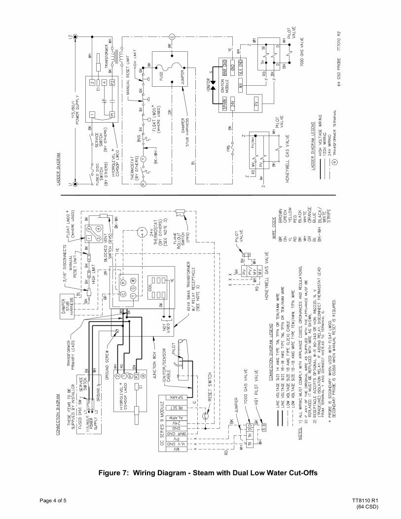
Figure 7: Wiring Diagram - Steam with Dual Low Water Cut-Offs

TT8110 R1
(64 CSD)
Page 5 of 5
Figure 8: Wiring Diagram - Water Boilers, Beckett 7600B Limit
Figure 9: Wiring Diagram - Water Boilers, Hydrolevel 3200 Limit