Series 40 M46 - Danfoss€¦ · Service Manual Series 40 M46 Variable Pumps 2 | ... should be...
48
Service Manual Series 40 M46 Variable Pumps powersolutions.danfoss.com
Transcript of Series 40 M46 - Danfoss€¦ · Service Manual Series 40 M46 Variable Pumps 2 | ... should be...

Service Manual
Series 40 M46Variable Pumps
powersolutions.danfoss.com
Revision history Table of revisions
Date Changed Rev
September 2017 minor edit - displacement limiter torque 0202
June 2014 Danfoss layout - add HC EDC Control BA
October 2010 corrections to port location illustration AE
March 2010 Fix Osaka address AD
March 2009 added spool alignment illustration AC
May 2008 Fixed the illustrations AB
October 2007 First edition AA
Service ManualSeries 40 M46 Variable Pumps
2 | © Danfoss | September 2017 11026743 | AX00000027en-US0202
IntroductionOverview..............................................................................................................................................................................................5Warranty.............................................................................................................................................................................................. 5General instructions........................................................................................................................................................................ 5
Remove the unit.......................................................................................................................................................................... 5Keep it clean..................................................................................................................................................................................5Replace all O-rings and gaskets............................................................................................................................................. 5
Safety precautions............................................................................................................................................................................5Symbols used in Danfoss literature............................................................................................................................................6Design...................................................................................................................................................................................................7The system circuit.............................................................................................................................................................................8
The basic closed circuit............................................................................................................................................................. 8Case drain and heat exchanger..............................................................................................................................................8
Pump schematic............................................................................................................................................................................... 9
Fluid and filter maintenanceFluid and filter recommendations........................................................................................................................................... 10
Hazardous material.................................................................................................................................................................. 10
Initial startup proceduresGeneral ..............................................................................................................................................................................................11Start-up procedure........................................................................................................................................................................ 11
Required tools and pressure measurementsRequired tools................................................................................................................................................................................. 12Port locations and gauge installation.....................................................................................................................................12
TroubleshootingOverview........................................................................................................................................................................................... 14Safety precautions......................................................................................................................................................................... 14System noise or vibration........................................................................................................................................................... 14System operating hot...................................................................................................................................................................14System will not operate in one direction.............................................................................................................................. 15System will not operate in either direction.......................................................................................................................... 15Neutral difficult or impossible to find.....................................................................................................................................16System response is sluggish...................................................................................................................................................... 16Electrical troubleshooting.......................................................................................................................................................... 17
AdjustmentsStandard procedures, inspections, and adjustments....................................................................................................... 18Warranty............................................................................................................................................................................................18Pump adjustment.......................................................................................................................................................................... 18Charge pressure relief valve.......................................................................................................................................................18Engaging the bypass function.................................................................................................................................................. 19System check/relief (SCR) valves.............................................................................................................................................. 20Displacement limiter adjustment............................................................................................................................................ 21Swashplate neutral adjustment................................................................................................................................................22
Measured data........................................................................................................................................................................... 22Pump Setup................................................................................................................................................................................ 22
Manual Displacement Control Neutral-Return Bracket Adjustment...........................................................................23Measured data........................................................................................................................................................................... 23Procedure.................................................................................................................................................................................... 23
Electric Displacement Control/Hydraulic Displacement Control Neutral Adjustment........................................ 24Measured data........................................................................................................................................................................... 24Procedure.................................................................................................................................................................................... 24
HC EDC Control...............................................................................................................................................................................25Control neutral adjustment.................................................................................................................................................. 25
Minor repairStandard procedures, removing the pump..........................................................................................................................28Displacement limiter.....................................................................................................................................................................28Pressure filtration adapter.......................................................................................................................................................... 29
Service ManualSeries 40 M46 Variable Pumps
Contents
© Danfoss | September 2017 11026743 | AX00000027en-US0202 | 3
Charge pump...................................................................................................................................................................................30Shaft seal, roller bearing and shaft replacement................................................................................................................32SCR valves......................................................................................................................................................................................... 33Charge pressure relief valve.......................................................................................................................................................34Bypass valve..................................................................................................................................................................................... 35Manual displacement control....................................................................................................................................................36Electronic displacement control/hydraulic displacement control.............................................................................. 37MDC orifice repair.......................................................................................................................................................................... 39EDC/HDC orifice repair.................................................................................................................................................................40HC EDC Control Repair................................................................................................................................................................. 41
Torque chartFastener size and torque chart..................................................................................................................................................44Plug size and torque chart..........................................................................................................................................................44
Service ManualSeries 40 M46 Variable Pumps
Contents
4 | © Danfoss | September 2017 11026743 | AX00000027en-US0202
Overview
This manual includes information for the installation, maintenance, and minor repair of the Series 40 M46pump. It includes a description of the unit and its individual components, troubleshooting information,and minor repair procedures.
Performing minor repairs requires the unit to be removed from the vehicle/machine. Thoroughly cleanthe unit before beginning maintenance, or repair activities. Since dirt and contamination are the greatestenemies of any type of hydraulic equipment, follow cleanliness requirements strictly. This is especiallyimportant when changing the system filter and when removing hoses or plumbing.
A worldwide network of Danfoss Global Service Partners is available for major repairs. Danfoss trainsGlobal Service Partners and certifies their facilities on a regular basis. You can locate your nearest GlobalService Partner using the distributor locator at www.powersolutions.danfoss.com.
Warranty
Performing installation, maintenance, and minor repairs according to the procedures in this manual willnot affect your warranty. Major repairs requiring the removal of a unit’s front flange voids the warrantyunless done by a Danfoss Global Service Partner.
General instructions
Follow these general procedures when repairing Series 40 M46 variable displacement closed circuitpumps.
Remove the unit
Prior to performing repairs, remove the unit from the vehicle/machine. Chock the wheels on the vehicleor lock the mechanism to inhibit movement. Be aware that hydraulic fluid may be under high pressureand/or hot. Inspect the outside of the pump and fittings for damage. Cap hoses and plug ports afterremoval to prevent contamination.
Keep it clean
Cleanliness is a primary means of assuring satisfactory pump life, on either new or repaired units. Cleanthe outside of the pump thoroughly before disassembly. Take care to avoid contamination of the systemports. Cleaning parts using a clean solvent wash and air drying is usually adequate.
As with any precision equipment, keep all parts free of foreign materials and chemicals. Protect allexposed sealing surfaces and open cavities from damage and foreign material. If left unattended, coverthe pump with a protective layer of plastic.
Replace all O-rings and gaskets
Danfoss reccommends you replace all O-rings, seals, and gaskets during repair. Lightly lubricate all O-rings with clean petroleum jelly prior to assembly.
Safety precautions
Always consider safety precautions before beginning a service procedure. Protect yourself and othersfrom injury. Take the following general precautions whenever servicing a hydraulic system.
Service ManualSeries 40 M46 Variable Pumps
Introduction
© Danfoss | September 2017 11026743 | AX00000027en-US0202 | 5
Unintended machine movement
W Warning
Unintended movement of the machine or mechanism may cause injury to the technician or bystanders.To protect against unintended movement, secure the machine or disable/disconnect the mechanismwhile servicing.
Flammable cleaning solvents
W Warning
Some cleaning solvents are flammable. To avoid possible fire, do not use cleaning solvents in an areawhere a source of ignition may be present.
Fluid under pressure
W Warning
Escaping hydraulic fluid under pressure can have sufficient force to penetrate your skin causing seriousinjury and/or infection. This fluid may also be hot enough to cause burns. Use caution when dealing withhydraulic fluid under pressure. Relieve pressure in the system before removing hoses, fittings, gauges, orcomponents. Never use your hand or any other body part to check for leaks in a pressurized line. Seekmedical attention immediately if you are cut by hydraulic fluid.
Personal safety
W Warning
Protect yourself from injury. Use proper safety equipment, including safety glasses, at all times.
Hazardous material
W Warning
Hydraulic fluid contains hazardous material. Avoid prolonged contact with hydraulic fluid. Alwaysdispose of used hydraulic fluid according to state, and federal environmental regulations.
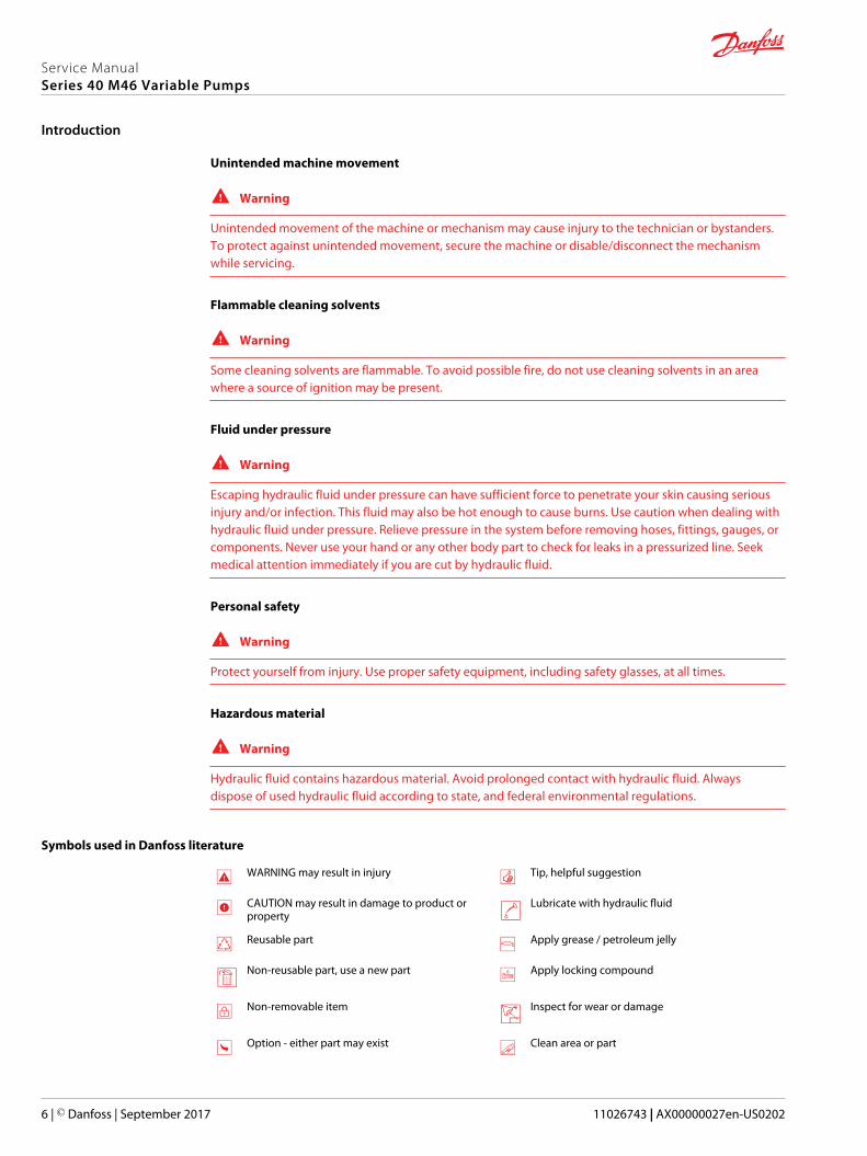
Symbols used in Danfoss literature
WARNING may result in injury Tip, helpful suggestion
CAUTION may result in damage to product orproperty
Lubricate with hydraulic fluid
Reusable part Apply grease / petroleum jelly
Non-reusable part, use a new part Apply locking compound
Non-removable item Inspect for wear or damage
Option - either part may exist Clean area or part
Service ManualSeries 40 M46 Variable Pumps
Introduction
6 | © Danfoss | September 2017 11026743 | AX00000027en-US0202
Superseded - parts are not interchangeable Be careful not to scratch or damage
Measurement required Note correct orientation
Flatness specification Mark orientation for reinstallation
Parallelism specification Torque specification
External hex head Press in - press fit
Internal hex head Pull out with tool – press fit
Torx head Cover splines with installation sleeve
O-ring boss port Pressure measurement/gauge location orspecification
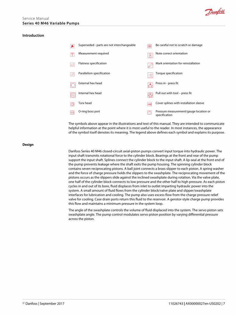
The symbols above appear in the illustrations and text of this manual. They are intended to communicatehelpful information at the point where it is most useful to the reader. In most instances, the appearanceof the symbol itself denotes its meaning. The legend above defines each symbol and explains its purpose.
Design
Danfoss Series 40 M46 closed-circuit axial-piston pumps convert input torque into hydraulic power. Theinput shaft transmits rotational force to the cylinder block. Bearings at the front and rear of the pumpsupport the input shaft. Splines connect the cylinder block to the input shaft. A lip-seal at the front end ofthe pump prevents leakage where the shaft exits the pump housing. The spinning cylinder blockcontains seven reciprocating pistons. A ball joint connects a brass slipper to each piston. A spring washerand the force of charge pressure holds the slippers to the swashplate. The reciprocating movement of thepistons occurs as the slippers slide against the inclined swashplate during rotation. Via the valve plate,one half of the cylinder block connects to low pressure and the other half to high pressure. As each pistoncycles in and out of its bore, fluid displaces from inlet to outlet imparting hydraulic power into thesystem. A small amount of fluid flows from the cylinder block/valve plate and slipper/swashplateinterfaces for lubrication and cooling. The pump also uses excess flow from the charge pressure reliefvalve for cooling. Case drain ports return this fluid to the reservoir. A gerotor-style charge pump providesthis flow and maintains a minimum pressure in the system loop.
The angle of the swashplate controls the volume of fluid displaced into the system. The servo piston setsswashplate angle. The pump control modulates servo piston position by varying differential pressureacross the piston.
Service ManualSeries 40 M46 Variable Pumps
Introduction
© Danfoss | September 2017 11026743 | AX00000027en-US0202 | 7
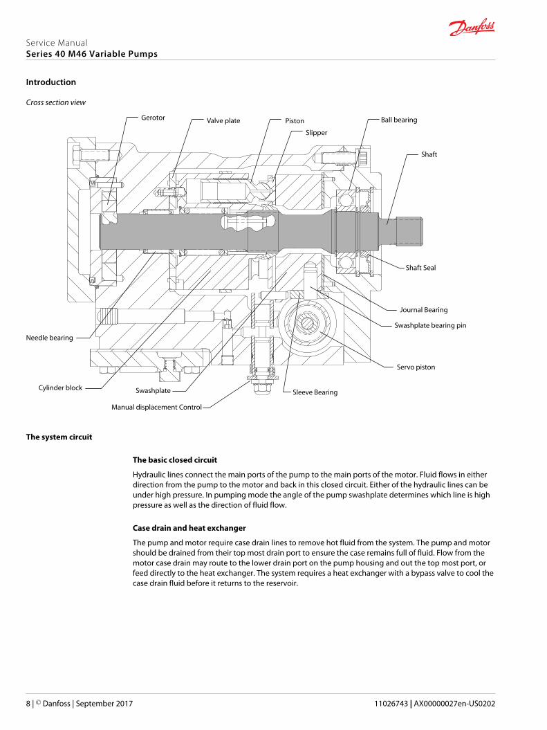
Cross section view
Piston
Slipper
Valve plate Ball bearing
Shaft
Journal Bearing
Swashplate bearing pin
Servo piston
SwashplateCylinder blockSleeve Bearing
Needle bearing
Manual displacement Control
Gerotor
Shaft Seal
The system circuit
The basic closed circuit
Hydraulic lines connect the main ports of the pump to the main ports of the motor. Fluid flows in eitherdirection from the pump to the motor and back in this closed circuit. Either of the hydraulic lines can beunder high pressure. In pumping mode the angle of the pump swashplate determines which line is highpressure as well as the direction of fluid flow.
Case drain and heat exchanger
The pump and motor require case drain lines to remove hot fluid from the system. The pump and motorshould be drained from their top most drain port to ensure the case remains full of fluid. Flow from themotor case drain may route to the lower drain port on the pump housing and out the top most port, orfeed directly to the heat exchanger. The system requires a heat exchanger with a bypass valve to cool thecase drain fluid before it returns to the reservoir.
Service ManualSeries 40 M46 Variable Pumps
Introduction
8 | © Danfoss | September 2017 11026743 | AX00000027en-US0202
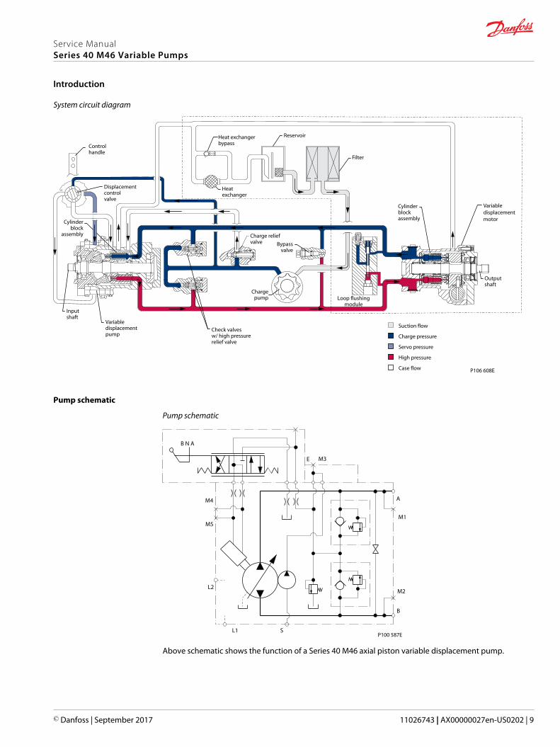
System circuit diagram
Inputshaft
Suction flow
Servo pressure
High pressure
Case flow
Charge pressure
Outputshaft
Cylinderblockassembly
Filter
Chargepump
Reservoir
Cylinderblock
assembly
Heatexchanger
Check valvesw/ high pressurerelief valve
Variabledisplacementpump
Heat exchangerbypass
Charge reliefvalve
Displacementcontrolvalve
Controlhandle
Bypassvalve
Loop flushingmodule
P106 608E
Variable displacement motor
Pump schematic
Pump schematic
B
M2
M1
A
E
L1
L2
M5
M4
S
M3
B N A
P100 587E
Above schematic shows the function of a Series 40 M46 axial piston variable displacement pump.
Service ManualSeries 40 M46 Variable Pumps
Introduction
© Danfoss | September 2017 11026743 | AX00000027en-US0202 | 9
Fluid and filter recommendations
To ensure optimum life, perform regular maintenance of the fluid and filter. Contaminated fluid is themain cause of unit failure. Take care to maintain fluid cleanliness when servicing.
Check the reservoir daily for proper fluid level, the presence of water, and rancid fluid odor. Fluidcontaminated by water may appear cloudy or milky, or free water may settle in the bottom of thereservoir. Rancid odor indicates the fluid was exposed to excessive heat. Change the fluid immediately ifthese conditions occur. Correct the problem immediately. Inspect vehicle for leaks daily.
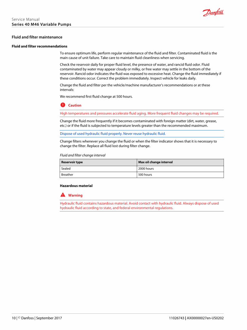
Change the fluid and filter per the vehicle/machine manufacturer’s recommendations or at theseintervals:
We recommend first fluid change at 500 hours.
C Caution
High temperatures and pressures accelerate fluid aging. More frequent fluid changes may be required.
Change the fluid more frequently if it becomes contaminated with foreign matter (dirt, water, grease,etc.) or if the fluid is subjected to temperature levels greater than the recommended maximum.
Dispose of used hydraulic fluid properly. Never reuse hydraulic fluid.
Change filters whenever you change the fluid or when the filter indicator shows that it is necessary tochange the filter. Replace all fluid lost during filter change.
Fluid and filter change interval
Reservoir type Max oil change interval
Sealed 2000 hours
Breather 500 hours
Hazardous material
W Warning
Hydraulic fluid contains hazardous material. Avoid contact with hydraulic fluid. Always dispose of usedhydraulic fluid according to state, and federal environmental regulations.
Service ManualSeries 40 M46 Variable Pumps
Fluid and filter maintenance
10 | © Danfoss | September 2017 11026743 | AX00000027en-US0202

General
Follow this procedure when starting-up a new pump installation or when restarting an installation inwhich the pump was removed. Ensure pump is thoroughly tested on a test stand before installing.
W Warning
Unintended movement of the machine or mechanism may cause injury to the technician or bystanders.To protect against unintended movement, secure the machine or disable/disconnect the mechanismwhile servicing.
Prior to installing the pump, inspect for shipping damage.
Start-up procedure
1. Ensure the machine hydraulic oil and system components (reservoir, hoses, valves, fittings, and heatexchanger) are clean and free of any foreign material.
2. Install new system filter element(s) if necessary. Check that inlet line fittings are properly tightenedand there are no air leaks.
3. Install the pump. Install a 50 bar [1000 psi] gauge in the charge pressure gauge port M
4. Fill the housing by adding filtered oil in the upper case drain port. Replace plug.
5. Fill the reservoir with hydraulic fluid of the recommended type and viscosity. Use a 10-micronreservoir filler filter. Ensure inlet line from reservoir to pump is filled.
6. Disconnect the pump from all control input signals.
After start-up the oil level in the reservoir may drop due to filling of the system components. Checkthe level in the reservoir to maintain a full oil level throughout start-up.
W Warning
Damage to hydraulic components may occur if you fail to maintain the oil supply.
7. Use a common method to disable the engine to prevent it from starting. Crank the starter for severalseconds. Do not to exceed the engine manufacturer’s recommendation. Wait 30 seconds and thencrank the engine a second time as stated above. This operation helps remove air from the systemlines. Refill the reservoir to recommended full oil level.
8. Check the pressure gauge at M3. When charge pressure begins to build, enable and start engine. Letthe engine run for a minimum of 30 seconds at low idle to allow the air to work itself out of thesystem. Check for leaks at all line connections and listen for cavitation. Check for proper fluid level inreservoir.
C Caution
Air entrapment in oil under high pressure may damage hydraulic components. Do not run atmaximum pressure until system is free of air and fluid has been thoroughly filtered.
9. When the pump estabishes adequate charge pressure (as shown in model code), increase enginespeed to normal operating rpm to further purge residual air from the system.
10. Shut off engine. Connect pump control signal. Start engine, checking to be certain pump remains inneutral. Run engine at normal operating speed and carefully check for forward and reverse controloperation.
11. Continue to cycle between forward and reverse for at least five minutes to bleed all air and flushsystem contaminants out of loop.
Normal charge pressure fluctuation may occur during forward and reverse operation.
12. Check that the reservoir is full. Remove charge pressure gauge. Re-intall charge pressure plug. Thepump is now ready for operation.
Service ManualSeries 40 M46 Variable Pumps
Initial startup procedures
© Danfoss | September 2017 11026743 | AX00000027en-US0202 | 11
Required tools
The service procedures described in this manual can be performed using common mechanic’s handtools. Special tools, if required, are shown. When testing system pressures, calibrate pressure gaugesfrequently to ensure accuracy. Use snubbers to protect gauges.
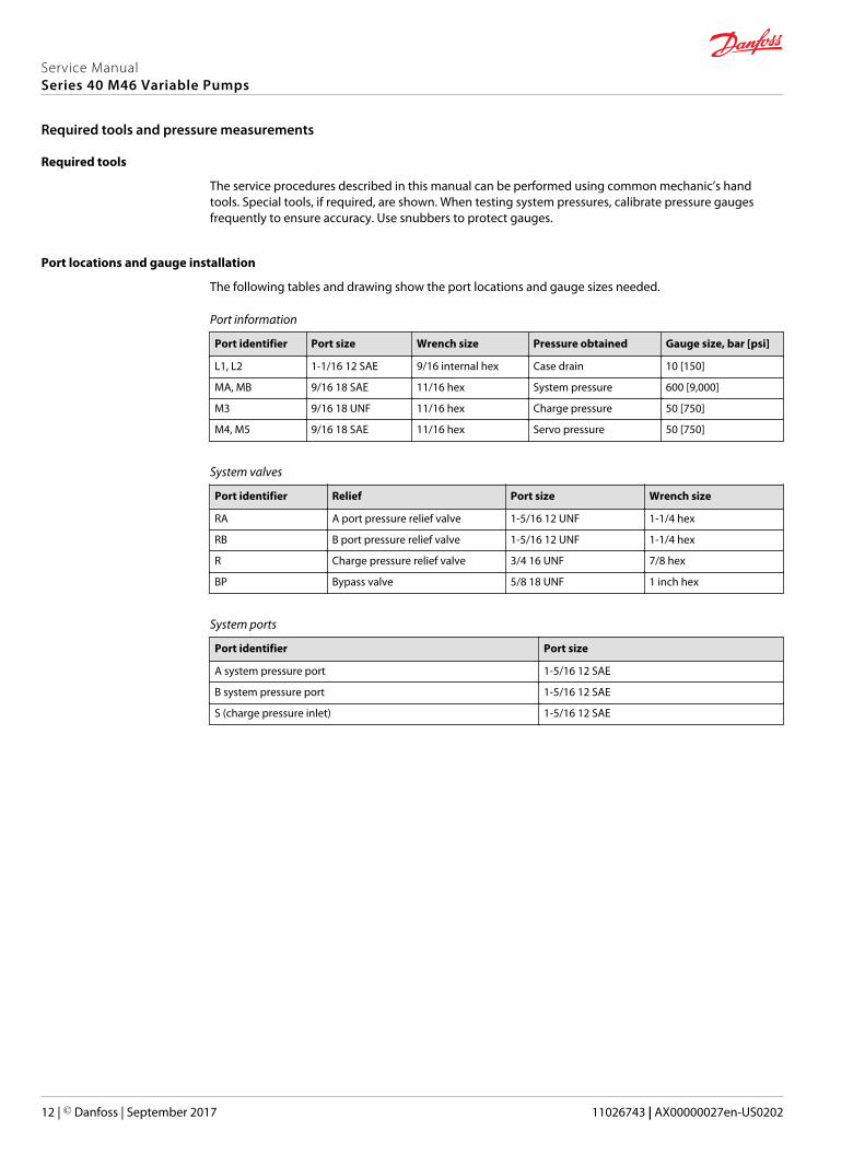
Port locations and gauge installation
The following tables and drawing show the port locations and gauge sizes needed.
Port information
Port identifier Port size Wrench size Pressure obtained Gauge size, bar [psi]
L1, L2 1-1/16 12 SAE 9/16 internal hex Case drain 10 [150]
MA, MB 9/16 18 SAE 11/16 hex System pressure 600 [9,000]
M3 9/16 18 UNF 11/16 hex Charge pressure 50 [750]
M4, M5 9/16 18 SAE 11/16 hex Servo pressure 50 [750]
System valves
Port identifier Relief Port size Wrench size
RA A port pressure relief valve 1-5/16 12 UNF 1-1/4 hex
RB B port pressure relief valve 1-5/16 12 UNF 1-1/4 hex
R Charge pressure relief valve 3/4 16 UNF 7/8 hex
BP Bypass valve 5/8 18 UNF 1 inch hex
System ports
Port identifier Port size
A system pressure port 1-5/16 12 SAE
B system pressure port 1-5/16 12 SAE
S (charge pressure inlet) 1-5/16 12 SAE
Service ManualSeries 40 M46 Variable Pumps
Required tools and pressure measurements
12 | © Danfoss | September 2017 11026743 | AX00000027en-US0202

Port locations
P106 604E
M4M5
L1
L2
B
A
MA
MBM3
RA
RB
R
S
BP
Service ManualSeries 40 M46 Variable Pumps
Required tools and pressure measurements
© Danfoss | September 2017 11026743 | AX00000027en-US0202 | 13
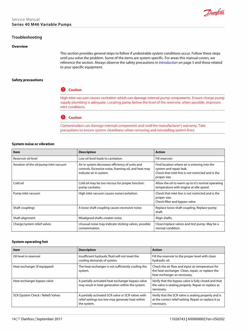
Overview
This section provides general steps to follow if undesirable system conditions occur. Follow these stepsuntil you solve the problem. Some of the items are system specific. For areas this manual covers, wereference the section. Always observe the safety precautions in Introduction on page 5 and those relatedto your specific equipment.
Safety precautions
C Caution
High inlet vacuum causes cavitation which can damage internal pump components. Ensure charge pumpsupply plumbing is adequate. Locating pump below the level of the reservoir, when possible, improvesinlet conditions.
C Caution
Contamination can damage internal components and void the manufacturer’s warranty. Takeprecautions to ensure system cleanliness when removing and reinstalling system lines
System noise or vibration
Item Description Action
Reservoir oil level Low oil level leads to cavitation. Fill reservoir.
Aeration of the oil/pump inlet vacuum Air in system decreases efficiency of units andcontrols. Excessive noise, foaming oil, and heat mayindicate air in system.
Find location where air is entering into thesystem and repair leak.Check that inlet line is not restricted and is theproper size.
Cold oil Cold oil may be too viscous for proper function:pump cavitates.
Allow the oil to warm up to it’s normal operatingtemperature with engine at idle speed.
Pump inlet vacuum High inlet vacuum causes noise/cavitation. Check that inlet line is not restricted and is theproper size.Check filter and bypass valve.
Shaft couplings A loose shaft coupling causes excessive noise. Replace loose shaft coupling. Replace pumpshaft.
Shaft alignment Misaligned shafts creates noise. Align shafts.
Charge/system relief valves Unusual noise may indicate sticking valves, possiblecontamination.
Clean/replace valves and test pump. May be anormal condition.
System operating hot
Item Description Action
Oil level in reservoir Insufficient hydraulic fluid will not meet thecooling demands of system.
Fill the reservoir to the proper level with cleanhydraulic oil.
Heat exchanger (if equipped) The heat exchanger is not sufficiently cooling thesystem.
Check the air flow and input air temperature forthe heat exchanger. Clean, repair, or replace theheat exchanger as necessary.
Heat exchanger bypass valve A partially activated heat exchanger bypass valvemay result in heat generation within the system.
Verify that the bypass valve is fully closed and thatthe valve is seating properly. Repair or replace asnecessary.
SCR (System Check / Relief) Valves A partially activated SCR valve or SCR valves withrelief settings too low may generate heat withinthe system.
Verify that the SCR valve is seating properly and isat the correct relief setting. Repair or replace it asnecessary.
Service ManualSeries 40 M46 Variable Pumps
Troubleshooting
14 | © Danfoss | September 2017 11026743 | AX00000027en-US0202
Item Description Action
Oil filters Clogged oil filters may result in an insufficientsupply of cool oil to the system.
Inspect the oil filters and verify that they are stilloperable. Replace them if necessary.
Machine load Excessive loads or extreme duty cycles can result inthe pump and/or motor operating at speeds andpressures beyond system design limitations.
Verify that the machine is operating within theparameters for which it was designed. If necessary,reduce the load on the machine.
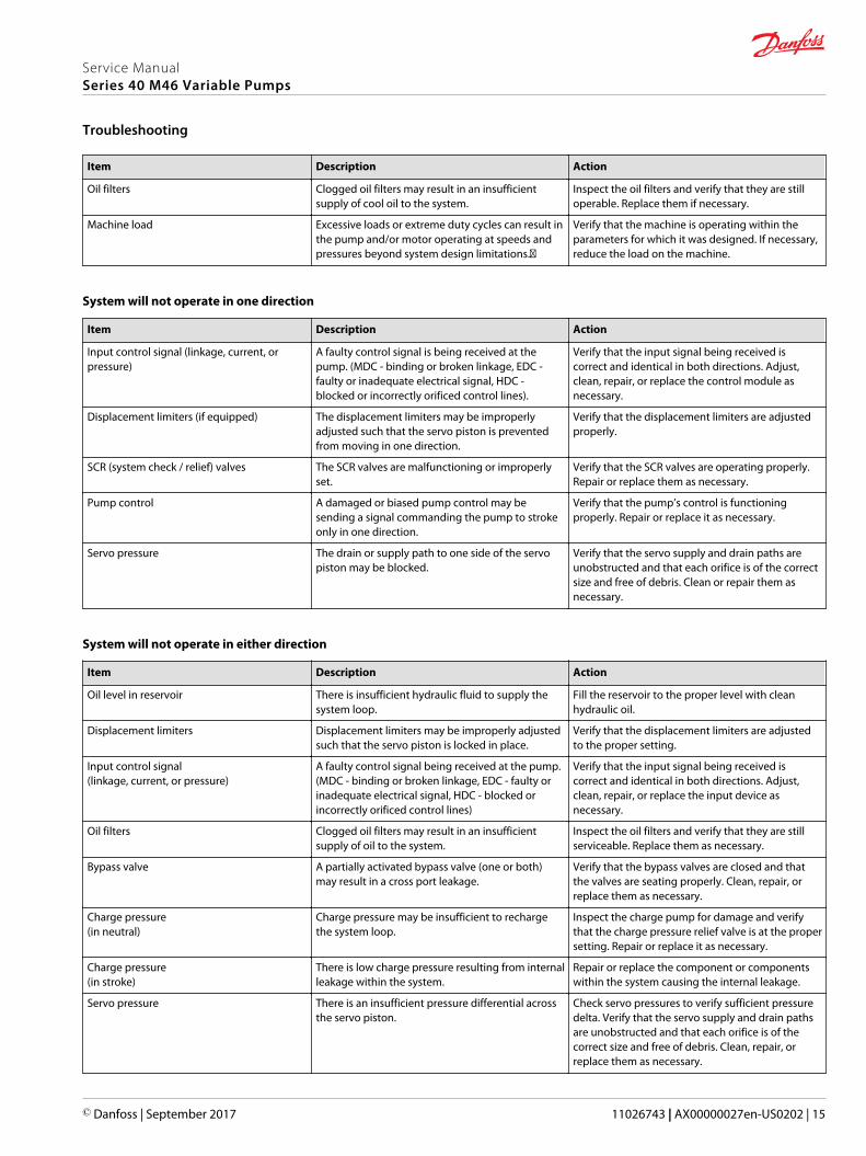
System will not operate in one direction
Item Description Action
Input control signal (linkage, current, orpressure)
A faulty control signal is being received at thepump. (MDC - binding or broken linkage, EDC -faulty or inadequate electrical signal, HDC -blocked or incorrectly orificed control lines).
Verify that the input signal being received iscorrect and identical in both directions. Adjust,clean, repair, or replace the control module asnecessary.
Displacement limiters (if equipped) The displacement limiters may be improperlyadjusted such that the servo piston is preventedfrom moving in one direction.
Verify that the displacement limiters are adjustedproperly.
SCR (system check / relief) valves The SCR valves are malfunctioning or improperlyset.
Verify that the SCR valves are operating properly.Repair or replace them as necessary.
Pump control A damaged or biased pump control may besending a signal commanding the pump to strokeonly in one direction.
Verify that the pump’s control is functioningproperly. Repair or replace it as necessary.
Servo pressure The drain or supply path to one side of the servopiston may be blocked.
Verify that the servo supply and drain paths areunobstructed and that each orifice is of the correctsize and free of debris. Clean or repair them asnecessary.
System will not operate in either direction
Item Description Action
Oil level in reservoir There is insufficient hydraulic fluid to supply thesystem loop.
Fill the reservoir to the proper level with cleanhydraulic oil.
Displacement limiters Displacement limiters may be improperly adjustedsuch that the servo piston is locked in place.
Verify that the displacement limiters are adjustedto the proper setting.
Input control signal(linkage, current, or pressure)
A faulty control signal being received at the pump.(MDC - binding or broken linkage, EDC - faulty orinadequate electrical signal, HDC - blocked orincorrectly orificed control lines)
Verify that the input signal being received iscorrect and identical in both directions. Adjust,clean, repair, or replace the input device asnecessary.
Oil filters Clogged oil filters may result in an insufficientsupply of oil to the system.
Inspect the oil filters and verify that they are stillserviceable. Replace them as necessary.
Bypass valve A partially activated bypass valve (one or both)may result in a cross port leakage.
Verify that the bypass valves are closed and thatthe valves are seating properly. Clean, repair, orreplace them as necessary.
Charge pressure(in neutral)
Charge pressure may be insufficient to rechargethe system loop.
Inspect the charge pump for damage and verifythat the charge pressure relief valve is at the propersetting. Repair or replace it as necessary.
Charge pressure(in stroke)
There is low charge pressure resulting from internalleakage within the system.
Repair or replace the component or componentswithin the system causing the internal leakage.
Servo pressure There is an insufficient pressure differential acrossthe servo piston.
Check servo pressures to verify sufficient pressuredelta. Verify that the servo supply and drain pathsare unobstructed and that each orifice is of thecorrect size and free of debris. Clean, repair, orreplace them as necessary.
Service ManualSeries 40 M46 Variable Pumps
Troubleshooting
© Danfoss | September 2017 11026743 | AX00000027en-US0202 | 15
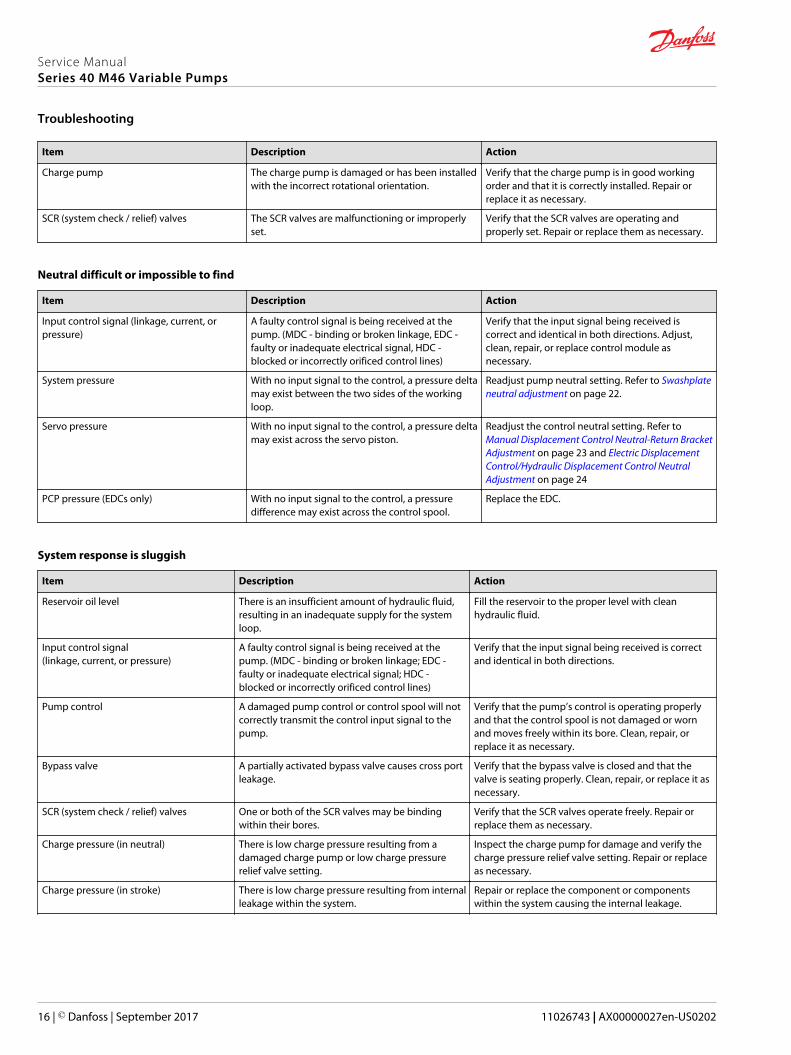
Item Description Action
Charge pump The charge pump is damaged or has been installedwith the incorrect rotational orientation.
Verify that the charge pump is in good workingorder and that it is correctly installed. Repair orreplace it as necessary.
SCR (system check / relief) valves The SCR valves are malfunctioning or improperlyset.
Verify that the SCR valves are operating andproperly set. Repair or replace them as necessary.
Neutral difficult or impossible to find
Item Description Action
Input control signal (linkage, current, orpressure)
A faulty control signal is being received at thepump. (MDC - binding or broken linkage, EDC -faulty or inadequate electrical signal, HDC -blocked or incorrectly orificed control lines)
Verify that the input signal being received iscorrect and identical in both directions. Adjust,clean, repair, or replace control module asnecessary.
System pressure With no input signal to the control, a pressure deltamay exist between the two sides of the workingloop.
Readjust pump neutral setting. Refer to Swashplateneutral adjustment on page 22.
Servo pressure With no input signal to the control, a pressure deltamay exist across the servo piston.
Readjust the control neutral setting. Refer to Manual Displacement Control Neutral-Return BracketAdjustment on page 23 and Electric DisplacementControl/Hydraulic Displacement Control NeutralAdjustment on page 24
PCP pressure (EDCs only) With no input signal to the control, a pressuredifference may exist across the control spool.
Replace the EDC.
System response is sluggish
Item Description Action
Reservoir oil level There is an insufficient amount of hydraulic fluid,resulting in an inadequate supply for the systemloop.
Fill the reservoir to the proper level with cleanhydraulic fluid.
Input control signal(linkage, current, or pressure)
A faulty control signal is being received at thepump. (MDC - binding or broken linkage; EDC -faulty or inadequate electrical signal; HDC -blocked or incorrectly orificed control lines)
Verify that the input signal being received is correctand identical in both directions.
Pump control A damaged pump control or control spool will notcorrectly transmit the control input signal to thepump.
Verify that the pump’s control is operating properlyand that the control spool is not damaged or wornand moves freely within its bore. Clean, repair, orreplace it as necessary.
Bypass valve A partially activated bypass valve causes cross portleakage.
Verify that the bypass valve is closed and that thevalve is seating properly. Clean, repair, or replace it asnecessary.
SCR (system check / relief) valves One or both of the SCR valves may be bindingwithin their bores.
Verify that the SCR valves operate freely. Repair orreplace them as necessary.
Charge pressure (in neutral) There is low charge pressure resulting from adamaged charge pump or low charge pressurerelief valve setting.
Inspect the charge pump for damage and verify thecharge pressure relief valve setting. Repair or replaceas necessary.
Charge pressure (in stroke) There is low charge pressure resulting from internalleakage within the system.
Repair or replace the component or componentswithin the system causing the internal leakage.
Service ManualSeries 40 M46 Variable Pumps
Troubleshooting
16 | © Danfoss | September 2017 11026743 | AX00000027en-US0202

Item Description Action
Servo pressure There is insufficient pressure differential across theservo piston.
Check servo pressures at port M4 and M5 to verifysufficient pressure delta. Verify that the servo supplyand drain paths are unobstructed and that eachorifice is of the correct size and free of debris. Clean,repair, or replace as necessary.
Charge pump The charge pump has been damaged or installedwith the incorrect rotational orientation.
Verify that the charge pump is in good working orderand that it is correctly installed. Repair or replace it asnecessary.
Electrical troubleshooting
Item Description Action
Control operates pump in one directiononly
Control coil had failed (EDC). Measure resistance at coil pins. Resistance should be14.20 ohms (24V) or 3.66 ohms (12V) at 20°C [70°F].Replace coil.
No pump function No power to controller. Restore power to controller.
Erratic pump function Electrical connection to pump is bad. Disconnect connection, check wires, reconnectwires.
Filter bypass indicator switch Filter switch may be bad. Check/replace filter switch. Add gauge to filterbypass port to verify proper fluid flow and verifyswitch operation by measuring resistance.open resistance=>510 ohms, closedresistance<=122 ohms.
Service ManualSeries 40 M46 Variable Pumps
Troubleshooting
© Danfoss | September 2017 11026743 | AX00000027en-US0202 | 17
Standard procedures, inspections, and adjustments
Before working on the pump, clean all dirt and grime from the outside of the pump and surroundingarea.
C Caution
Contamination can damage internal components and void the manufacturer’s warranty. Takeprecautions to ensure system cleanliness when removing and reinstalling system lines.
1. If removing the pump, tag each hydraulic line. If you disconnect hydraulic lines, plug each open portto ensure that dirt and contamination do not get into the pump.
2. Inpect the hydraulic fluid for signs of system contamination, oil discoloration, foam in the oil, sludge,or small metal particles.
3. If there are signs of contamination in the hydraulic fluid, replace all filters and drain and clean thehydraulic system. Fill with the correct hydraulic fluid.
4. Flush the lines before replacing the hydraulic fluid.
5. Before re-installing the pump, test for leaks.
Warranty
Performing installation, maintenance, and minor repairs according to the procedures in this manual willnot affect your warranty. Major repairs requiring the removal of a unit’s front flange voids the warrantyunless done by a Danfoss Global Service Partner.
Pump adjustment
This section offers instruction on adjustment of pump components. Read through the entire topic beforebeginning a service activity. Refer to Port locations and gauge installation on page 12, for location ofgauge ports and suggested gauge size.
Charge pressure relief valve
This procedure explains how to check and adjust the charge pressure relief valve.
1. Install a 50 bar [1000 psi] pressure gauge in charge pressure gauge port M3. Install a 10 bar [100 psi]gauge in one of the case pressure ports L1 or L2. Operate the system with the pump in neutral (zerodisplacement) when measuring charge pressure.
2. To adjust charge pressure, shut down system.
3. Using a 1 inch hex wrench, remove charge pressure relief plug (102). Add or remove shims (101) inrelief valve. Adding shims increases charge pressure, while removing shims decreases chargepressure.
4. Lubricate and install new O-ring (103).
5. Using a 1 inch hex wrench, reinstall plug. Torque to 108 N•m [80 lbf•ft].
6. Operate pump in neutral to verify proper charge setting. Charge pressure is referenced to casepressure. Subtract case pressure (L1/L2) from charge pressure (M3) to compute actual setting. Repeatsteps 1-5 if necessary.
Service ManualSeries 40 M46 Variable Pumps
Adjustments
18 | © Danfoss | September 2017 11026743 | AX00000027en-US0202
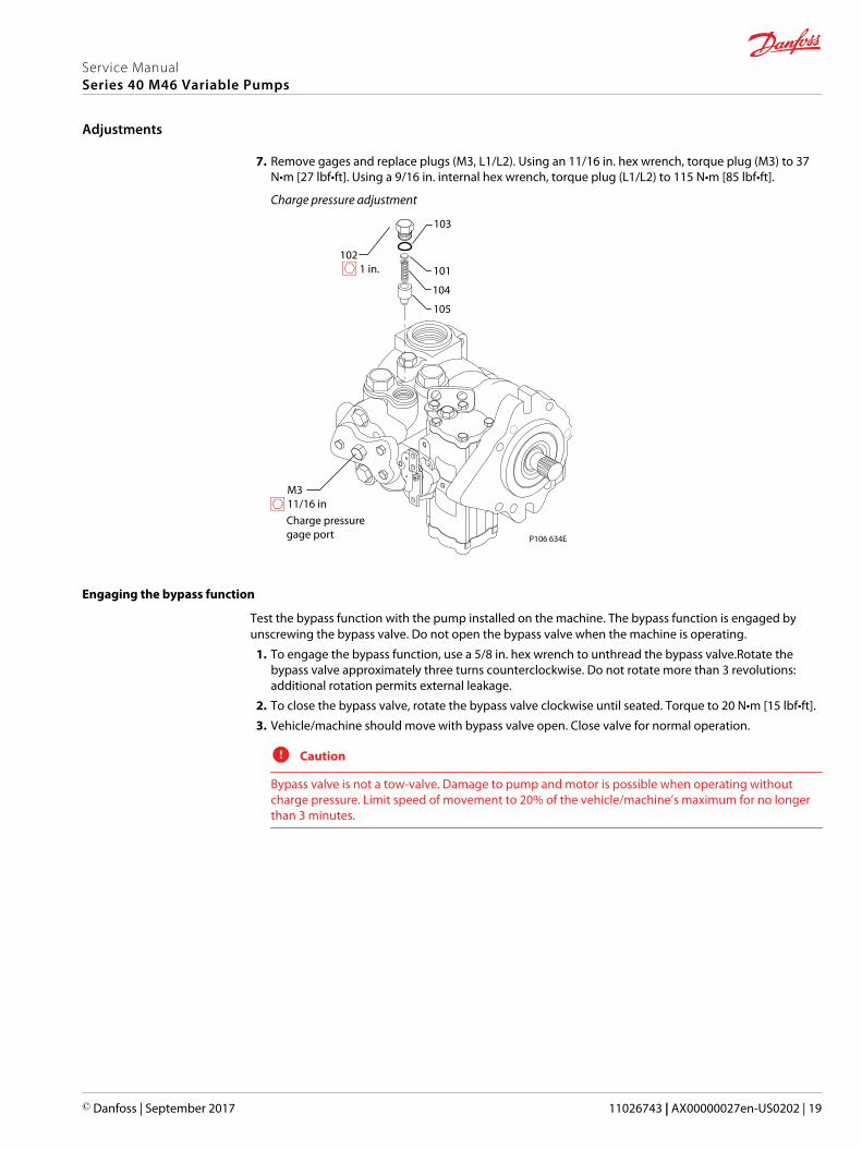
7. Remove gages and replace plugs (M3, L1/L2). Using an 11/16 in. hex wrench, torque plug (M3) to 37N•m [27 lbf•ft]. Using a 9/16 in. internal hex wrench, torque plug (L1/L2) to 115 N•m [85 lbf•ft].
Charge pressure adjustment
P106 634E
103
105
104
101
102 1 in.
M311/16 in
Charge pressuregage port
Engaging the bypass function
Test the bypass function with the pump installed on the machine. The bypass function is engaged byunscrewing the bypass valve. Do not open the bypass valve when the machine is operating.
1. To engage the bypass function, use a 5/8 in. hex wrench to unthread the bypass valve.Rotate thebypass valve approximately three turns counterclockwise. Do not rotate more than 3 revolutions:additional rotation permits external leakage.
2. To close the bypass valve, rotate the bypass valve clockwise until seated. Torque to 20 N•m [15 lbf•ft].
3. Vehicle/machine should move with bypass valve open. Close valve for normal operation.
C Caution
Bypass valve is not a tow-valve. Damage to pump and motor is possible when operating withoutcharge pressure. Limit speed of movement to 20% of the vehicle/machine’s maximum for no longerthan 3 minutes.
Service ManualSeries 40 M46 Variable Pumps
Adjustments
© Danfoss | September 2017 11026743 | AX00000027en-US0202 | 19

Using the bypass function
P106 633E
Bypass check valve 5/8 in
System check/relief (SCR) valves
The SCR valve is a high pressure relief valve and a system check valve in combination. Whenever an SCRvalve is replaced or opened, opperate the pump in its full range of functions to ensure proper machineoperation. The SCR valves are pre-set at the factory, no adjustment is possible. Pressure code is markedon the valve. Refer to the model code for pressure designation. If you suspect SCR malfunction, replacevalve and test operation of pump.
This procedure explains how to replace the SCR valves.
1. Shut down the system.
2. Using a 1-1/4 in. hex wrench, remove relief valve plug (166).
3. Remove spring (165) and relief valve (1103) from pump housing.
4. Insert new relief valve and spring into pump housing.
5. Lubricate and install new O-ring (106).
Service ManualSeries 40 M46 Variable Pumps
Adjustments
20 | © Danfoss | September 2017 11026743 | AX00000027en-US0202
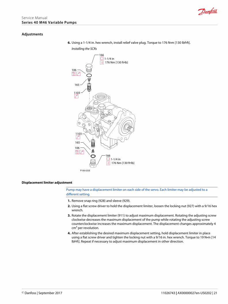
6. Using a 1-1/4 in. hex wrench, install relief valve plug. Torque to 176 N•m [130 lbf•ft].
Installing the SCRs
P106 635E
106
165
1103
166 1-1/4 in 176 Nm [130 ft•lb]
106
165
1103
166 1-1/4 in 176 Nm [130 ft•lb]
Displacement limiter adjustment
Pump may have a displacement limiter on each side of the servo. Each limiter may be adjusted to adifferent setting.
1. Remove snap ring (928) and sleeve (929).
2. Using a flat screw driver to hold the displacement limiter, loosen the locking nut (927) with a 9/16 hexwrench.
3. Rotate the displacement limiter (911) to adjust maximum displacement. Rotating the adjusting screwclockwise decreases the maximum displacement of the pump while rotating the adjusting screwcounterclockwise increases the maximum displacement. The displacement changes approximately 4cm³ per revolution.
4. After establishing the desired maximum displacement setting, hold displacement limiter in placeusing a flat screw driver and tighten the locking nut with a 9/16 in. hex wrench. Torque to 19 N•m [14lbf•ft]. Repeat if necessary to adjust maximum displacement in other direction.
Service ManualSeries 40 M46 Variable Pumps
Adjustments
© Danfoss | September 2017 11026743 | AX00000027en-US0202 | 21
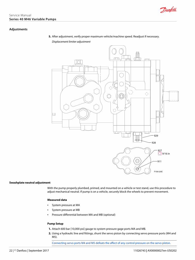
5. After adjustment, verify proper maximum vehicle/machine speed. Readjust if necessary.
Displacement limiter adjustment
P106 626E
927 9/16 in
911
929
928
Swashplate neutral adjustment
With the pump properly plumbed, primed, and mounted on a vehicle or test stand, use this procedure toadjust mechanical neutral. If pump is on a vehicle, securely block the wheels to prevent movement.
Measured data
• System pressure at MA
• System pressure at MB
• Pressure differential between MA and MB (optional)
Pump Setup
1. Attach 600 bar [10,000 psi] gauge to system pressure gage ports MA and MB.
2. Using a hydraulic line and fittings, shunt the servo piston by connecting servo pressure ports (M4 andM5).
Connecting servo ports M4 and M5 defeats the affect of any control pressure on the servo piston.
Service ManualSeries 40 M46 Variable Pumps
Adjustments
22 | © Danfoss | September 2017 11026743 | AX00000027en-US0202

3. Run prime mover at normal operating speed.
4. Use a 1/4 hex wrench to hold adjusting screw (908) in place and a 9/16 hex wrench to loosen servolock nut (115).
5. Turn neutral adjustment screw (908) until one system pressure gage begins to show an increase inpressure. Note position of screw. Turn the neutral adjustment screw (908) in the opposite directionuntil the other system pressure gage begins to show an increase in pressure. Note position of screw.Turn the neutral adjustment screw half way between the two postitions.
6. Use a 1/4 hex wrench to hold the servo adjustment screw in place, and a 9/16 hex wrench to tightenservo lock nut (115). Torque to 37 N•m [27 lbf•ft].
7. Shut down prime mover and remove previously installed gauges and fittings. Plug ports MA, MB, M4,and M5.
Servo neutral adjustment
P106 630E
908 1/4 in
115 11/16 in
Connect PortsM4 and M5
Manual Displacement Control Neutral-Return Bracket Adjustment
With the pump properly plumbed, primed, and mounted on a vehicle or test stand, use the followingprocedure to adjust the pump displacement control to neutral position. If pump is on a vehicle, securelyblock the wheels to prevent movement. Check swashplate mechanical neutral adjustment beforeadjusting control bracket. Refer to previous topic Swashplate neutral adjustment on page 22 forinstructions. If swashplate neutral is properly adjusted and system is not in neutral, adjust MDC bracket asdescribed below.
Measured data
• Servo pressure at M4
• Servo pressure at M5
• Pressure differential between M4 and M5 (optional)
Procedure
1. Attach 20 bar [300 psi] gauge to each servo gage port M4 and M5. Run prime mover at normaloperating speed.
2. Using a 3/8 in. hex wrench, loosen screw (1210) allowing the neutral bracket to move, but not freely.
3. Start prime mover and slowly accelerate to normal operating rpm.
4. Using your hand, press neutral bracket towards the pump housing, and rotate it until one of the servopressure gages indicates an increase in pressure. Note position of bracket. Rotate neutral bracket in
Service ManualSeries 40 M46 Variable Pumps
Adjustments
© Danfoss | September 2017 11026743 | AX00000027en-US0202 | 23
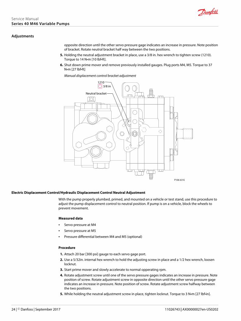
opposite direction until the other servo pressure gage indicates an increase in pressure. Note positionof bracket. Rotate neutral bracket half way between the two positions.
5. Holding the neutral adjustment bracket in place, use a 3/8 in. hex wrench to tighten screw (1210).Torque to 14 N•m [10 lbf•ft].
6. Shut down prime mover and remove previously installed gauges. Plug ports M4, M5. Torque to 37N•m [27 lbf•ft]
Manual displacement control bracket adjustment
P106 631E
1210 3/8 in
Neutral bracket
Electric Displacement Control/Hydraulic Displacement Control Neutral Adjustment
With the pump properly plumbed, primed, and mounted on a vehicle or test stand, use this procedure toadjust the pump displacement control to neutral position. If pump is on a vehicle, block the wheels toprevent movement.
Measured data
• Servo pressure at M4
• Servo pressure at M5
• Pressure differential between M4 and M5 (optional)
Procedure
1. Attach 20 bar [300 psi] gauge to each servo gage port.
2. Use a 5/32in. internal hex wrench to hold the adjusting screw in place and a 1/2 hex wrench, loosenlocknut.
3. Start prime mover and slowly accelerate to normal opperating rpm.
4. Rotate adjustment screw until one of the servo pressure gages indicates an increase in pressure. Noteposition of screw. Rotate adjustment screw in opposite direction until the other servo pressure gageindicates an increase in pressure. Note position of screw. Rotate adjustment screw halfway betweenthe two positions.
5. While holding the neutral adjustment screw in place, tighten locknut. Torque to 3 N•m [27 lbf•in].
Service ManualSeries 40 M46 Variable Pumps
Adjustments
24 | © Danfoss | September 2017 11026743 | AX00000027en-US0202
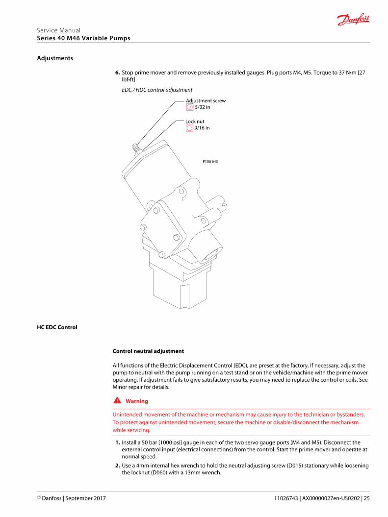
6. Stop prime mover and remove previously installed gauges. Plug ports M4, M5. Torque to 37 N•m [27lbf•ft]
EDC / HDC control adjustment
Adjustment screw 5/32 in
Lock nut 9/16 in
P106 643
HC EDC Control
Control neutral adjustment
All functions of the Electric Displacement Control (EDC), are preset at the factory. If necessary, adjust thepump to neutral with the pump running on a test stand or on the vehicle/machine with the prime moveroperating. If adjustment fails to give satisfactory results, you may need to replace the control or coils. SeeMinor repair for details.
W Warning
Unintended movement of the machine or mechanism may cause injury to the technician or bystanders.To protect against unintended movement, secure the machine or disable/disconnect the mechanismwhile servicing.
1. Install a 50 bar [1000 psi] gauge in each of the two servo gauge ports (M4 and M5). Disconnect theexternal control input (electrical connections) from the control. Start the prime mover and operate atnormal speed.
2. Use a 4mm internal hex wrench to hold the neutral adjusting screw (D015) stationary while looseningthe locknut (D060) with a 13mm wrench.
Service ManualSeries 40 M46 Variable Pumps
Adjustments
© Danfoss | September 2017 11026743 | AX00000027en-US0202 | 25
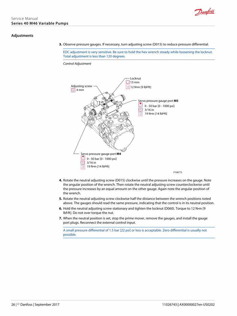
3. Observe pressure gauges. If necessary, turn adjusting screw (D015) to reduce pressure differential.
EDC adjustment is very sensitive. Be sure to hold the hex wrench steady while loosening the locknut.Total adjustment is less than 120 degrees.
Control Adjustment
Adjusting screw 4 mm
Locknut13 mm
12 N•m [9 lbf•ft]
Servo pressure gauge port M5
0 - 50 bar [0 - 1000 psi]3/16 in19 N•m [14 lbf•ft]
Servo pressure gauge port M4
0 - 50 bar [0 - 1000 psi]3/16 in19 N•m [14 lbf•ft]
P108773
4. Rotate the neutral adjusting screw (D015) clockwise until the pressure increases on the gauge. Notethe angular position of the wrench. Then rotate the neutral adjusting screw counterclockwise untilthe pressure increases by an equal amount on the other gauge. Again note the angular position ofthe wrench.
5. Rotate the neutral adjusting screw clockwise half the distance between the wrench positions notedabove. The gauges should read the same pressure, indicating that the control is in its neutral position.
6. Hold the neutral adjusting screw stationary and tighten the locknut (D060). Torque to 12 N•m [9lbf•ft]. Do not over torque the nut.
7. When the neutral position is set, stop the prime mover, remove the gauges, and install the gaugeport plugs. Reconnect the external control input.
A small pressure differential of 1.5 bar [22 psi] or less is acceptable. Zero differential is usually notpossible.
Service ManualSeries 40 M46 Variable Pumps
Adjustments
26 | © Danfoss | September 2017 11026743 | AX00000027en-US0202

Neutral Adjustment (EDC) (bottom view)
Solenoid shaft
Feedback pin
Adjusting screw(cam)
P106 046E
Maximumadjustmentless than 120°
Control spool
Illustration shows how cam on adjusting pin rotates to adjust for neutral position after pump is re-installed.
Service ManualSeries 40 M46 Variable Pumps
Adjustments
© Danfoss | September 2017 11026743 | AX00000027en-US0202 | 27
Standard procedures, removing the pump
Before working on the pump, clean all dirt and grime from the outside.
If the pump has an auxiliary pump attached, remove both pumps as a single unit.Tag all hydraulic lines asthey are disconnected and plug all open ports to ensure that dirt and contamination do not get into thepump.
C Caution
Contamination can damage internal components and void the manufacturer’s warranty. Takeprecautions to ensure system cleanliness when removing and reinstalling system lines.
Removal
1. With the prime mover off, thoroughly clean all dirt and grime from the outside of the pump.
2. Tag and disconnect each hydraulic line connected to the pump. As hydraulic lines are disconnected,plug each open port, to ensure that dirt and contamination do not get into the pump.
3. Remove the pump and its auxiliary pump (if applicable) as a single unit.
C Caution
Be careful not to damage solenoids and electrical connections when using straps or chains to removepump from machine.
Inspection
1. Ensure the work surface and surrounding area are clean and free of contaminants such as dirt andgrime.
2. Inspect the hydraulic fluid for signs of system contamination, oil discoloration, foam in the oil, sludge,or small metal particles.
Reassembly
1. Before replacing the pump on the machine, replace all filters and drain the hydraulic system. Fill thesystem with the correct, filtered, hydraulic fluid.
2. Flush the lines before replacing the hydraulic fluid.
For repair part information, see Danfoss publication Series 40 M46 Variable Pump Parts ManualBLN-2-41701 for your model.
Displacement limiter
Removal
Only remove displacement limiter (911) if replacement is necessary. Mark the location of displacementadjustment and neutral adjustment screws before disassembly. This saves time during re-assembly.
1. Remove snap ring (928) and sleeve (929). Use a 1/4 in. hex wrench to hold neutral adjustment screwin place. Use a 9/16 in. hex wrench to remove hex nut (115).
2. Use a flat screw driver to hold displacement limiter (911) in place. Use a 9/16 in. hex wrench toremove lock nut (927).
3. Using a 3/8 in. hex wrench, remove five bolts (921) from servo cover (902).
4. Unscrew servo cover (902) to remove it from neutral adjustment screw. Remove and discard gasket(936).
5. Turn displacement limiter (911) out of servo cover (902).
Service ManualSeries 40 M46 Variable Pumps
Minor repair
28 | © Danfoss | September 2017 11026743 | AX00000027en-US0202
Inspection
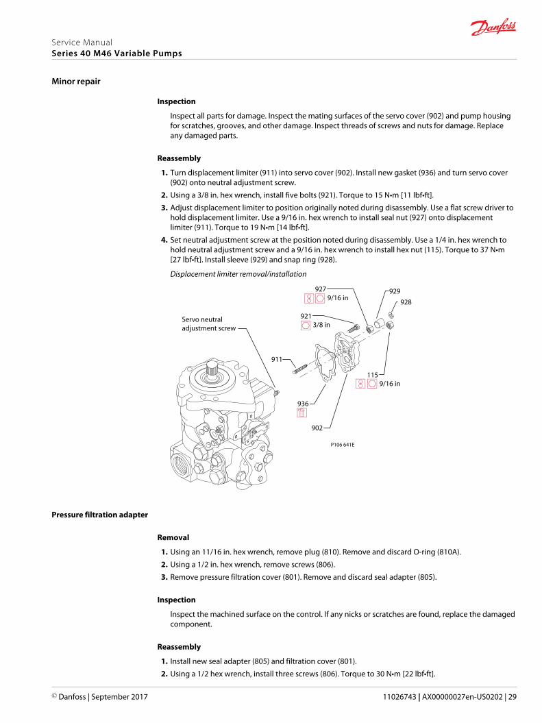
Inspect all parts for damage. Inspect the mating surfaces of the servo cover (902) and pump housingfor scratches, grooves, and other damage. Inspect threads of screws and nuts for damage. Replaceany damaged parts.
Reassembly
1. Turn displacement limiter (911) into servo cover (902). Install new gasket (936) and turn servo cover(902) onto neutral adjustment screw.
2. Using a 3/8 in. hex wrench, install five bolts (921). Torque to 15 N•m [11 lbf•ft].
3. Adjust displacement limiter to position originally noted during disassembly. Use a flat screw driver tohold displacement limiter. Use a 9/16 in. hex wrench to install seal nut (927) onto displacementlimiter (911). Torque to 19 N•m [14 lbf•ft].
4. Set neutral adjustment screw at the position noted during disassembly. Use a 1/4 in. hex wrench tohold neutral adjustment screw and a 9/16 in. hex wrench to install hex nut (115). Torque to 37 N•m[27 lbf•ft]. Install sleeve (929) and snap ring (928).
Displacement limiter removal/installation
P106 641E
936
902
921 3/8 in
911
115 9/16 in
927 9/16 in
Servo neutral adjustment screw
929
928
Pressure filtration adapter
Removal
1. Using an 11/16 in. hex wrench, remove plug (810). Remove and discard O-ring (810A).
2. Using a 1/2 in. hex wrench, remove screws (806).
3. Remove pressure filtration cover (801). Remove and discard seal adapter (805).
Inspection
Inspect the machined surface on the control. If any nicks or scratches are found, replace the damagedcomponent.
Reassembly
1. Install new seal adapter (805) and filtration cover (801).
2. Using a 1/2 hex wrench, install three screws (806). Torque to 30 N•m [22 lbf•ft].
Service ManualSeries 40 M46 Variable Pumps
Minor repair
© Danfoss | September 2017 11026743 | AX00000027en-US0202 | 29
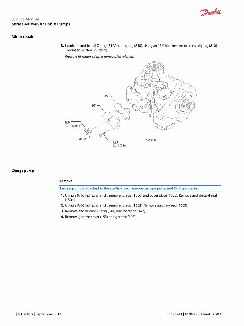
3. Lubricate and install O-ring (810A) onto plug (810). Using an 11/16 in. hex wrench, install plug (810).Torque to 37 N•m [27 lbf•ft].
Pressure filtration adapter removal/installation
805
801
810 11/16 in
810A P106 642E806 1/2 in
Charge pump
Removal
If a gear pump is attached to the auxiliary pad, remove the gear pump and O-ring or gasket.
1. Using a 9/16 in. hex wrench, remove screws (1506) and cover plate (1505). Remove and discard seal(1504).
2. Using a 9/16 in. hex wrench, remove screws (1502). Remove auxiliary pad (1503).
3. Remove and discard O-ring (141) and load ring (142).
4. Remove gerotor cover (155) and gerotor (603).
Service ManualSeries 40 M46 Variable Pumps
Minor repair
30 | © Danfoss | September 2017 11026743 | AX00000027en-US0202
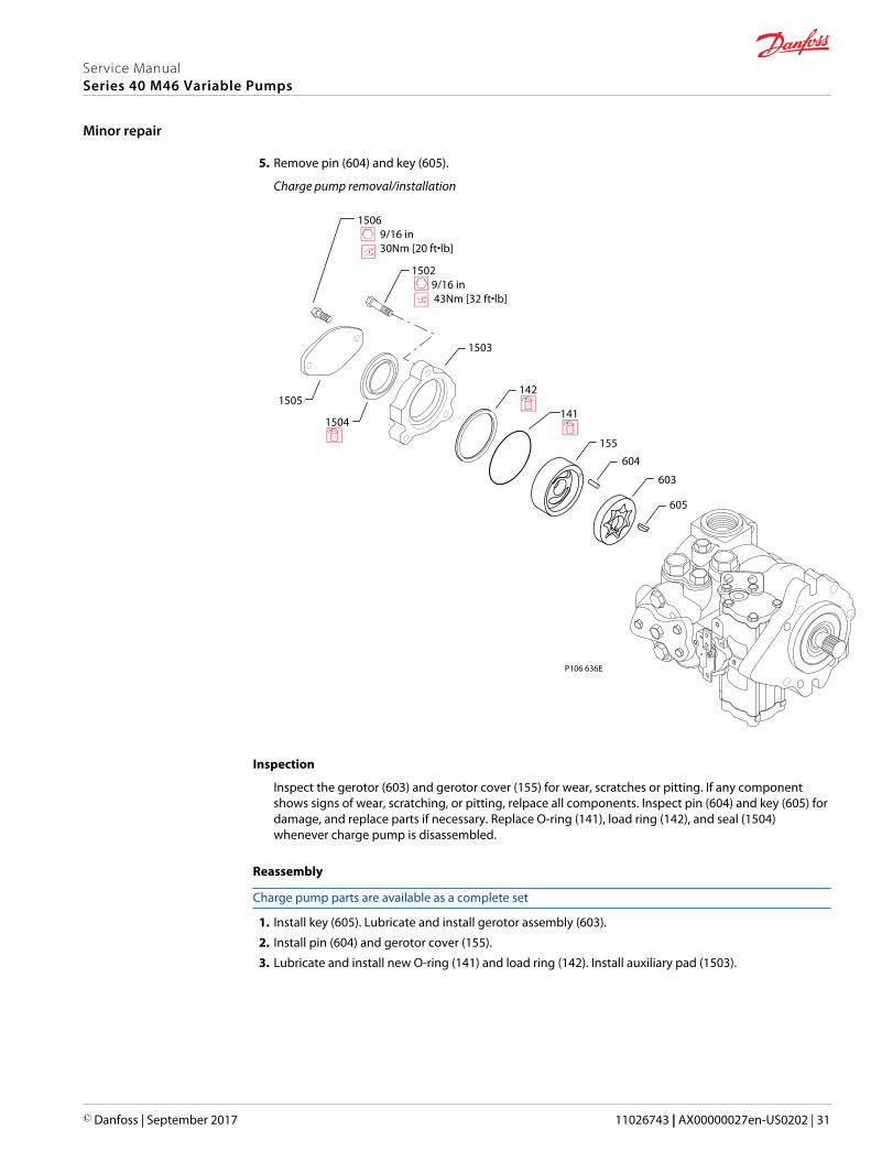
5. Remove pin (604) and key (605).
Charge pump removal/installation
155
141
142
603
605
604
1503
1502 9/16 in 43Nm [32 ft•lb]
1504
1506 9/16 in 30Nm [20 ft•lb]
1505
P106 636E
Inspection
Inspect the gerotor (603) and gerotor cover (155) for wear, scratches or pitting. If any componentshows signs of wear, scratching, or pitting, relpace all components. Inspect pin (604) and key (605) fordamage, and replace parts if necessary. Replace O-ring (141), load ring (142), and seal (1504)whenever charge pump is disassembled.
Reassembly
Charge pump parts are available as a complete set
1. Install key (605). Lubricate and install gerotor assembly (603).
2. Install pin (604) and gerotor cover (155).
3. Lubricate and install new O-ring (141) and load ring (142). Install auxiliary pad (1503).
Service ManualSeries 40 M46 Variable Pumps
Minor repair
© Danfoss | September 2017 11026743 | AX00000027en-US0202 | 31
4. Using a 9/16 in. hex wrench, install screws (1502). Torque to 43 N•m [32 lb•ft].
5. Lubricate and press seal (1504) onto auxiliary pad (1503).If a gear pump is a ttached to the auxiliary pad, install a new O-ring or gasket and gear pump
6. Install cover plate (1505). Using a 9/16 in. hex wrench, install capscrews (1506). Torque to 30 N•m [22lbf•ft].If a gear pump is attached, seal (1504), cover (1505), and bolts (1506) are not used. Replace O-ring orgasket between gear pump and M46 pump.
Shaft seal, roller bearing and shaft replacement
The shaft assembly is serviceable without removing the front cover of the pump, but the charge pumpmust be removed first. Orient the pump on the work surface so the shaft is pointing up with the chargepump (603) and key (605) removed from shaft. See Charge pump on page 30
Removal
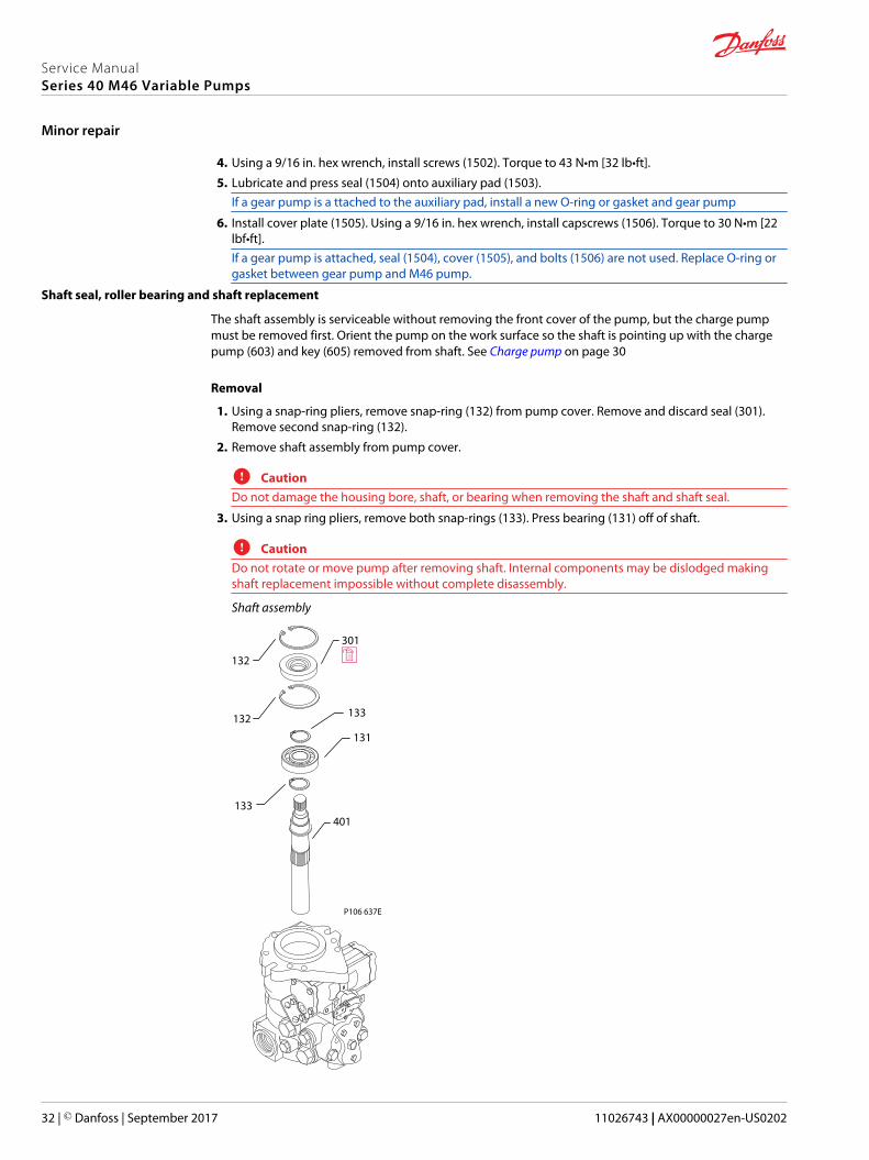
1. Using a snap-ring pliers, remove snap-ring (132) from pump cover. Remove and discard seal (301).Remove second snap-ring (132).
2. Remove shaft assembly from pump cover.
C CautionDo not damage the housing bore, shaft, or bearing when removing the shaft and shaft seal.
3. Using a snap ring pliers, remove both snap-rings (133). Press bearing (131) off of shaft.
C CautionDo not rotate or move pump after removing shaft. Internal components may be dislodged makingshaft replacement impossible without complete disassembly.
Shaft assembly
P106 637E
401
132
132
133
133
131
301
Service ManualSeries 40 M46 Variable Pumps
Minor repair
32 | © Danfoss | September 2017 11026743 | AX00000027en-US0202

Inspection
Inspect the shaft and bearing for wear, scratching and pits. If wear, scratching or pitting is found,replace the shaft and bearing. Rotate bearing while feeling for roughness. Replace bearing if itdoesn’t spin freely.
Reassembly
1. Using a snap ring pliers, install snap-ring (133 ). Lubricate and press bearing (131) onto shaft. Installsecond snap-ring (133).
2. Install shaft and bearing assembly into front cover. Rotate shaft to align with block-splines. Ensurebearing is installed deep enough to clear snapring groove.
3. Using a snap ring pliers, install snapring (132).
4. Cover shaft splines with an installation sleeve to protect lipseal during installation. Lubricate andpress new seal (301) into pump cover.
5. Install second snap-ring (132). Remove installation sleeve.
Shaft seal installation tool
P106 652E
7 in
2.75 in
0.370 in
0.750 in
3 in
2.45 in
1.5 in
1.24 in
SCR valves
The SCR valves are factory set and are not field adjustable.
Removal
1. Using a 1-1/4 in. hex wrench, remove relief valve plug (166). Remove and discard Oring (106).
2. Remove spring (165) and relief valve (1103) from pump housing.
Inspection
Inspect the sealing surfaces of the pump for nicks or scratches. Inspect the relief valve (1103) sealingsurface for nicks or scratches. If the relief valve (1103) is damaged, replace it.
Reassembly
1. Lubricate and insert relief valve (1103) and spring (165) into pump housing.
Service ManualSeries 40 M46 Variable Pumps
Minor repair
© Danfoss | September 2017 11026743 | AX00000027en-US0202 | 33
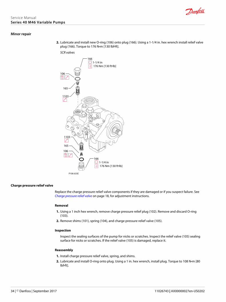
2. Lubricate and install new O-ring (106) onto plug (166). Using a 1-1/4 in. hex wrench install relief valveplug (166). Torque to 176 N•m [130 lbf•ft].
SCR valves
P106 635E
106
165
1103
166 1-1/4 in 176 Nm [130 ft•lb]
106
165
1103
166 1-1/4 in 176 Nm [130 ft•lb]
Charge pressure relief valve
Replace the charge pressure relief valve components if they are damaged or if you suspect failure. See Charge pressure relief valve on page 18, for adjustment instructions.
Removal
1. Using a 1 inch hex wrench, remove charge pressure relief plug (102). Remove and discard O-ring(103).
2. Remove shims (101), spring (104), and charge pressure relief valve (105).
Inspection
Inspect the sealing surfaces of the pump for nicks or scratches. Inspect the relief valve (105) sealingsurface for nicks or scratches. If the relief valve (105) is damaged, replace it.
Reassembly
1. Install charge pressure relief valve, spring, and shims.
2. Lubricate and install O-ring onto plug. Using a 1 in. hex wrench, install plug. Torque to 108 N•m [80lbf•ft].
Service ManualSeries 40 M46 Variable Pumps
Minor repair
34 | © Danfoss | September 2017 11026743 | AX00000027en-US0202
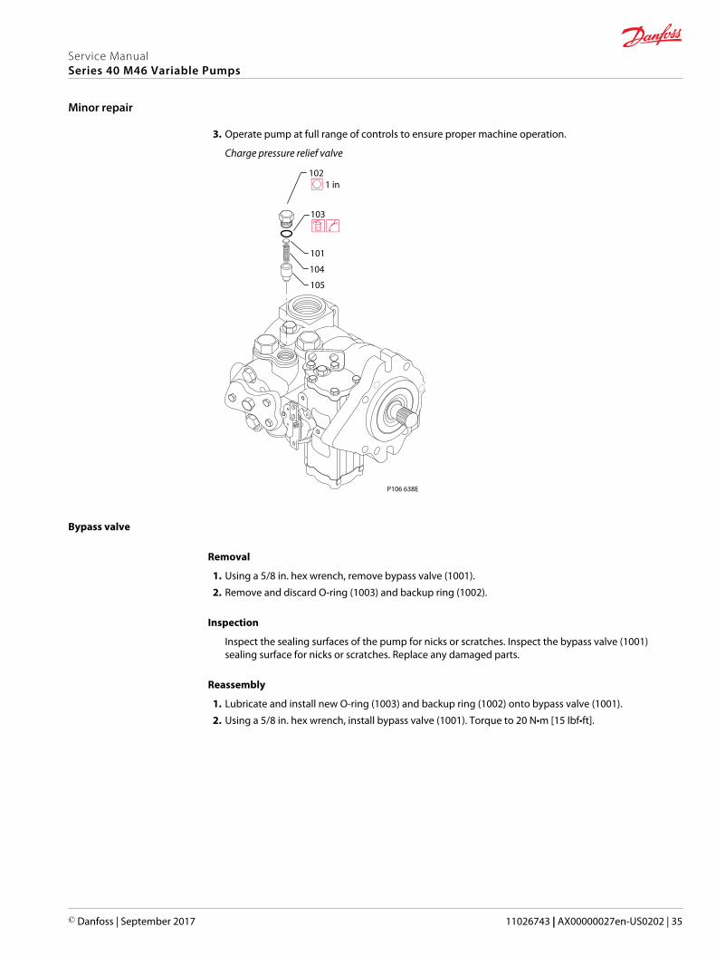
3. Operate pump at full range of controls to ensure proper machine operation.
Charge pressure relief valve
P106 638E
103
105
104
101
102 1 in
Bypass valve
Removal
1. Using a 5/8 in. hex wrench, remove bypass valve (1001).
2. Remove and discard O-ring (1003) and backup ring (1002).
Inspection
Inspect the sealing surfaces of the pump for nicks or scratches. Inspect the bypass valve (1001)sealing surface for nicks or scratches. Replace any damaged parts.
Reassembly
1. Lubricate and install new O-ring (1003) and backup ring (1002) onto bypass valve (1001).
2. Using a 5/8 in. hex wrench, install bypass valve (1001). Torque to 20 N•m [15 lbf•ft].
Service ManualSeries 40 M46 Variable Pumps
Minor repair
© Danfoss | September 2017 11026743 | AX00000027en-US0202 | 35
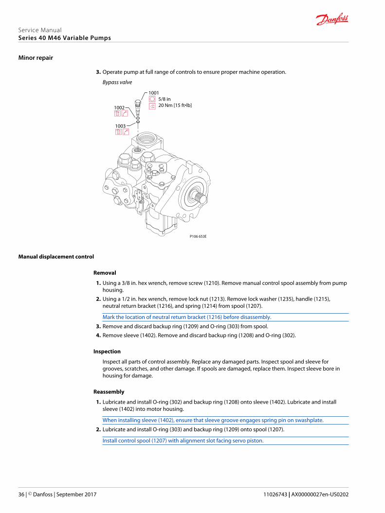
3. Operate pump at full range of controls to ensure proper machine operation.
Bypass valve
P106 653E
1002
1003
1001 5/8 in 20 Nm [15 ft•lb]
Manual displacement control
Removal
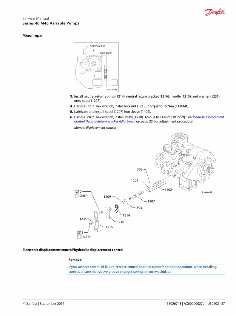
1. Using a 3/8 in. hex wrench, remove screw (1210). Remove manual control spool assembly from pumphousing.
2. Using a 1/2 in. hex wrench, remove lock nut (1213). Remove lock washer (1235), handle (1215),neutral return bracket (1216), and spring (1214) from spool (1207).
Mark the location of neutral return bracket (1216) before disassembly.
3. Remove and discard backup ring (1209) and O-ring (303) from spool.
4. Remove sleeve (1402). Remove and discard backup ring (1208) and O-ring (302).
Inspection
Inspect all parts of control assembly. Replace any damaged parts. Inspect spool and sleeve forgrooves, scratches, and other damage. If spools are damaged, replace them. Inspect sleeve bore inhousing for damage.
Reassembly
1. Lubricate and install O-ring (302) and backup ring (1208) onto sleeve (1402). Lubricate and installsleeve (1402) into motor housing.
When installing sleeve (1402), ensure that sleeve groove engages spring pin on swashplate.
2. Lubricate and install O-ring (303) and backup ring (1209) onto spool (1207).
Install control spool (1207) with alignment slot facing servo piston.
Service ManualSeries 40 M46 Variable Pumps
Minor repair
36 | © Danfoss | September 2017 11026743 | AX00000027en-US0202
P107 958E
Servo piston
Alignment slot
3. Install neutral return spring (1214), neutral return bracket (1216), handle (1215), and washer (1235)onto spool (1207).
4. Using a 1/2 in. hex wrench, install lock nut (1213). Torque to 15 N•m [11 lbf•ft].
5. Lubricate and install spool (1207) into sleeve (1402).
6. Using a 3/8 in. hex wrench, install screw (1210). Torque to 14 N•m [10 lbf•ft]. See Manual DisplacementControl Neutral-Return Bracket Adjustment on page 23, for adjustment procedure.
Manual displacement control
P106 639E
1213 1/2 in
1210 3/8 in
302
1214
1216
1215
1208
1235
1207
303
1209
1402
Electronic displacement control/hydraulic displacement control
Removal
If you suspect control of failure, replace control and test pump for proper operation. When installingcontrol, ensure that sleeve groove engages spring pin on swashplate.
Service ManualSeries 40 M46 Variable Pumps
Minor repair
© Danfoss | September 2017 11026743 | AX00000027en-US0202 | 37
1. Using a 3/16 in. internal hex wrench, remove screws (1203 and 1204) or (1224). If you have a threeposition controll, remove screws (1226) using a 4 mm internal hex wrench.
2. Remove control housing (1201) or manifold (1225). Remove and discard O-rings (1220 and 304) or(1227, 1228, and 1223A).
Inspection
Inspect control spool for scratches, grooves, and other damage. If spool is damaged, or you suspectcontrol malfunction, replace entire control unit. Inspect sleeve bore in housing for damage.
Reassembly
1. Lubricate and install O-rings (1220 and 304) onto control housing (1201) or for a three positioncontrol, lubricate and install O-rings(1227 and 1228) onto manifold (1225) and O-rings (1229) ontocontrol housing (1223). Install control housing (1201) or manifold (1225) onto pump housing, alignsleeve groove with spring pin on swashplate.
Service ManualSeries 40 M46 Variable Pumps
Minor repair
38 | © Danfoss | September 2017 11026743 | AX00000027en-US0202
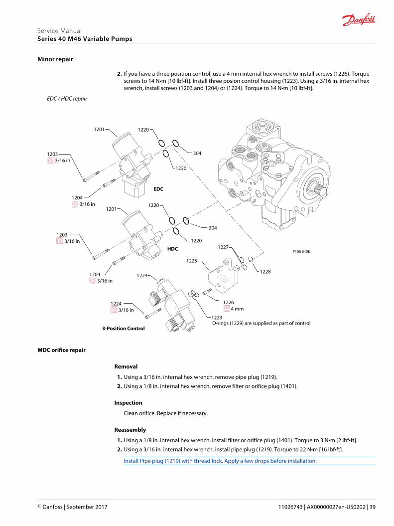
2. If you have a three position control, use a 4 mm internal hex wrench to install screws (1226). Torquescrews to 14 N•m [10 lbf•ft]. Install three posion control housing (1223). Using a 3/16 in. internal hexwrench, install screws (1203 and 1204) or (1224). Torque to 14 N•m [10 lbf•ft].
EDC / HDC repair
P106 640E
EDC
304
12201201
1220
1203 3/16 in
1204 3/16 in
304
12201201
1220
HDC
1203 3/16 in
1204 3/16 in
1228
1227
1225
1224 3/16 in
1226 4 mm
1223
3-Position Control
1229O-rings (1229) are supplied as part of control
MDC orifice repair
Removal
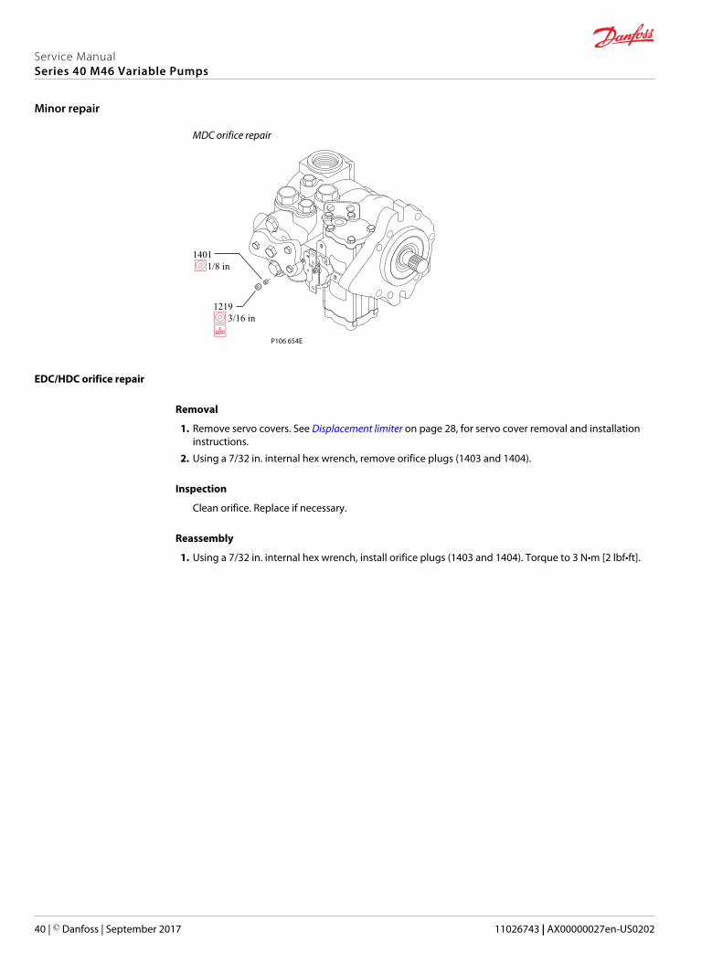
1. Using a 3/16 in. internal hex wrench, remove pipe plug (1219).
2. Using a 1/8 in. internal hex wrench, remove filter or orifice plug (1401).
Inspection
Clean orifice. Replace if necessary.
Reassembly
1. Using a 1/8 in. internal hex wrench, install filter or orifice plug (1401). Torque to 3 N•m [2 lbf•ft].
2. Using a 3/16 in. internal hex wrench, install pipe plug (1219). Torque to 22 N•m [16 lbf•ft].
Install Pipe plug (1219) with thread lock. Apply a few drops before installation.
Service ManualSeries 40 M46 Variable Pumps
Minor repair
© Danfoss | September 2017 11026743 | AX00000027en-US0202 | 39
MDC orifice repair
P106 654E
1219 3/16 in
1401 1/8 in
EDC/HDC orifice repair
Removal
1. Remove servo covers. See Displacement limiter on page 28, for servo cover removal and installationinstructions.
2. Using a 7/32 in. internal hex wrench, remove orifice plugs (1403 and 1404).
Inspection
Clean orifice. Replace if necessary.
Reassembly
1. Using a 7/32 in. internal hex wrench, install orifice plugs (1403 and 1404). Torque to 3 N•m [2 lbf•ft].
Service ManualSeries 40 M46 Variable Pumps
Minor repair
40 | © Danfoss | September 2017 11026743 | AX00000027en-US0202
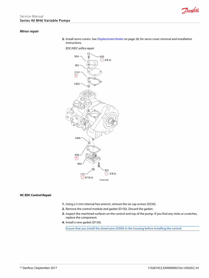
2. Install servo covers. See Displacement limiter on page 28, for servo cover removal and installationinstructions.
EDC/HDC orifice repair
P106 655E
936
902
921 3/8 in
115 9/16 in
1403
1404
920 3/8 in
2161
934
901
HC EDC Control Repair
1. Using a 5 mm internal hex wrench, remove the six cap screws (D250).
2. Remove the control module and gasket (D150). Discard the gasket.
3. Inspect the machined surfaces on the control and top of the pump. If you find any nicks or scratches,replace the component.
4. Install a new gasket (D150).
Ensure that you install the dowel pins (D300) in the housing before installing the control.
Service ManualSeries 40 M46 Variable Pumps
Minor repair
© Danfoss | September 2017 11026743 | AX00000027en-US0202 | 41
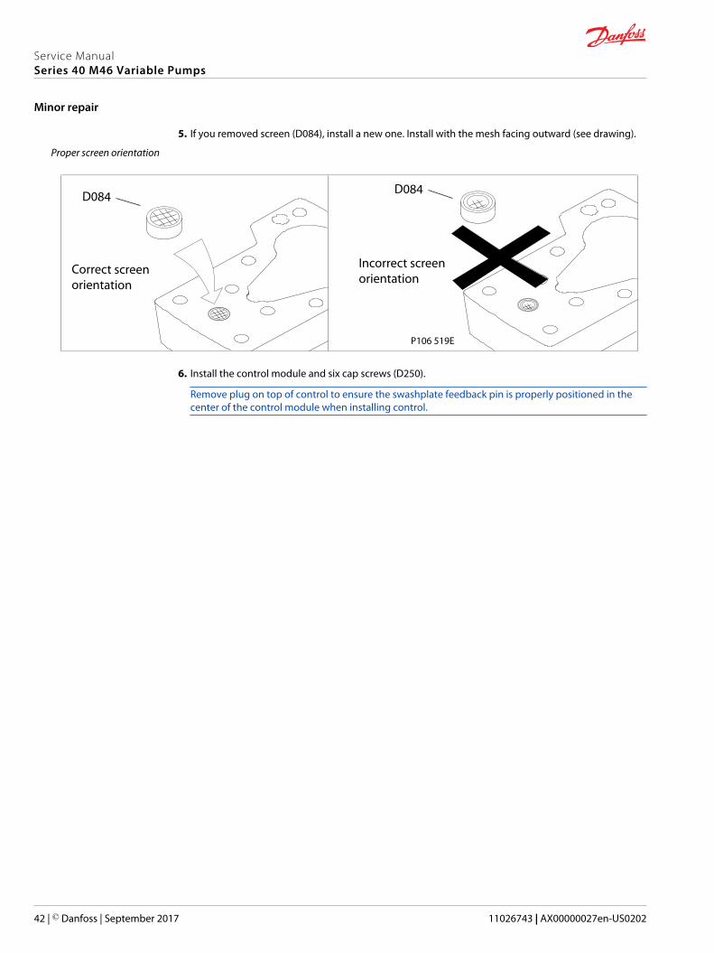
5. If you removed screen (D084), install a new one. Install with the mesh facing outward (see drawing).
Proper screen orientation
P106 519E
D084D084
Incorrect screenorientation
Correct screenorientation
6. Install the control module and six cap screws (D250).
Remove plug on top of control to ensure the swashplate feedback pin is properly positioned in thecenter of the control module when installing control.
Service ManualSeries 40 M46 Variable Pumps
Minor repair
42 | © Danfoss | September 2017 11026743 | AX00000027en-US0202
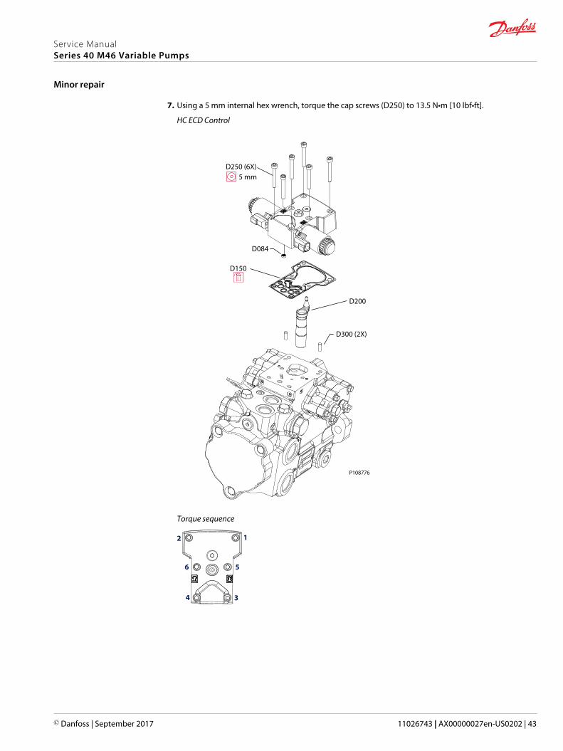
7. Using a 5 mm internal hex wrench, torque the cap screws (D250) to 13.5 N•m [10 lbf•ft].
HC ECD Control
P108776
D250 (6X)
5 mm
D150
D200
D300 (2X)
D084
Torque sequence
2
34
56
1
Service ManualSeries 40 M46 Variable Pumps
Minor repair
© Danfoss | September 2017 11026743 | AX00000027en-US0202 | 43
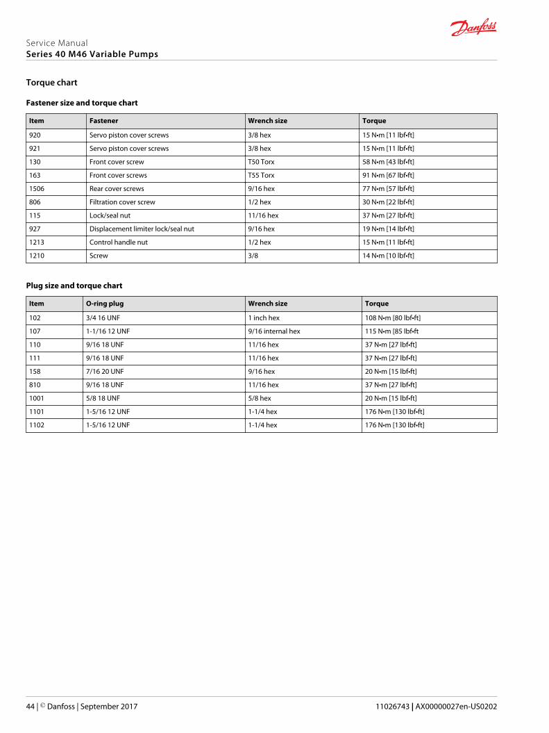
Fastener size and torque chart
Item Fastener Wrench size Torque
920 Servo piston cover screws 3/8 hex 15 N•m [11 lbf•ft]
921 Servo piston cover screws 3/8 hex 15 N•m [11 lbf•ft]
130 Front cover screw T50 Torx 58 N•m [43 lbf•ft]
163 Front cover screws T55 Torx 91 N•m [67 lbf•ft]
1506 Rear cover screws 9/16 hex 77 N•m [57 lbf•ft]
806 Filtration cover screw 1/2 hex 30 N•m [22 lbf•ft]
115 Lock/seal nut 11/16 hex 37 N•m [27 lbf•ft]
927 Displacement limiter lock/seal nut 9/16 hex 19 N•m [14 lbf•ft]
1213 Control handle nut 1/2 hex 15 N•m [11 lbf•ft]
1210 Screw 3/8 14 N•m [10 lbf•ft]
Plug size and torque chart
Item O-ring plug Wrench size Torque
102 3/4 16 UNF 1 inch hex 108 N•m [80 lbf•ft]
107 1-1/16 12 UNF 9/16 internal hex 115 N•m [85 lbf•ft
110 9/16 18 UNF 11/16 hex 37 N•m [27 lbf•ft]
111 9/16 18 UNF 11/16 hex 37 N•m [27 lbf•ft]
158 7/16 20 UNF 9/16 hex 20 N•m [15 lbf•ft]
810 9/16 18 UNF 11/16 hex 37 N•m [27 lbf•ft]
1001 5/8 18 UNF 5/8 hex 20 N•m [15 lbf•ft]
1101 1-5/16 12 UNF 1-1/4 hex 176 N•m [130 lbf•ft]
1102 1-5/16 12 UNF 1-1/4 hex 176 N•m [130 lbf•ft]
Service ManualSeries 40 M46 Variable Pumps
Torque chart
44 | © Danfoss | September 2017 11026743 | AX00000027en-US0202
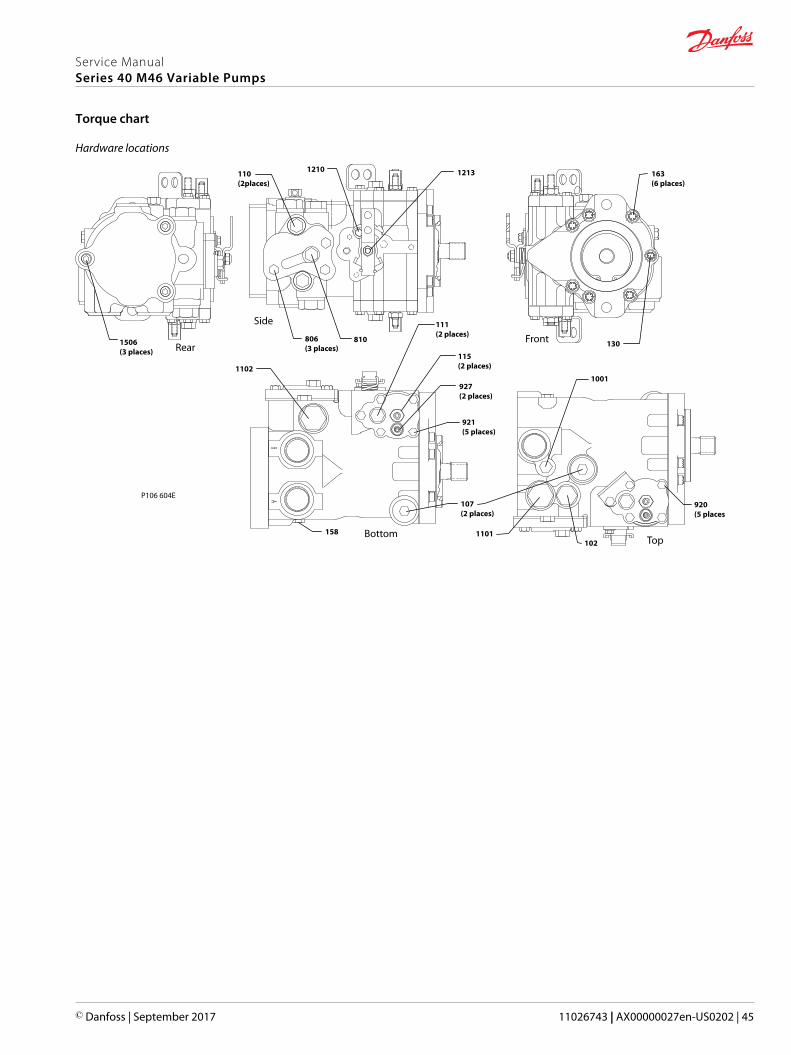
Hardware locations
P106 604E
111(2 places)
810
110(2places)
1213
1101
1102
102
1001
158
806(3 places)
1506(3 places)
163(6 places)
130
115(2 places)
927(2 places)
921(5 places)
1210
920(5 places)
107(2 places)
FrontRear
BottomTop
Side
Service ManualSeries 40 M46 Variable Pumps
Torque chart
© Danfoss | September 2017 11026743 | AX00000027en-US0202 | 45
Service ManualSeries 40 M46 Variable Pumps
46 | © Danfoss | September 2017 11026743 | AX00000027en-US0202
Service ManualSeries 40 M46 Variable Pumps
© Danfoss | September 2017 11026743 | AX00000027en-US0202 | 47
Danfoss Power Solutions is a global manufacturer and supplier of high-quality hydraulic andelectronic components. We specialize in providing state-of-the-art technology and solutionsthat excel in the harsh operating conditions of the mobile off-highway market. Building onour extensive applications expertise, we work closely with our customers to ensureexceptional performance for a broad range of off-highway vehicles.
We help OEMs around the world speed up system development, reduce costs and bringvehicles to market faster.
Danfoss – Your Strongest Partner in Mobile Hydraulics.
Go to www.powersolutions.danfoss.com for further product information.
Wherever off-highway vehicles are at work, so is Danfoss. We offer expert worldwide supportfor our customers, ensuring the best possible solutions for outstanding performance. Andwith an extensive network of Global Service Partners, we also provide comprehensive globalservice for all of our components.
Please contact the Danfoss Power Solution representative nearest you.
Local address:
Danfoss Power Solutions GmbH & Co. OHGKrokamp 35D-24539 Neumünster, GermanyPhone: +49 4321 871 0
Danfoss Power Solutions ApSNordborgvej 81DK-6430 Nordborg, DenmarkPhone: +45 7488 2222
Danfoss Power Solutions (US) Company2800 East 13th StreetAmes, IA 50010, USAPhone: +1 515 239 6000
Danfoss Power Solutions Trading(Shanghai) Co., Ltd.Building #22, No. 1000 Jin Hai RdJin Qiao, Pudong New DistrictShanghai, China 201206Phone: +86 21 3418 5200
Danfoss can accept no responsibility for possible errors in catalogues, brochures and other printed material. Danfoss reserves the right to alter its products without notice. This also applies to productsalready on order provided that such alterations can be made without changes being necessary in specifications already agreed.All trademarks in this material are property of the respective companies. Danfoss and the Danfoss logotype are trademarks of Danfoss A/S. All rights reserved.
© Danfoss | September 2017 11026743 | AX00000027en-US0202
Products we offer:
• Bent Axis Motors
• Closed Circuit Axial PistonPumps and Motors
• Displays
• Electrohydraulic PowerSteering
• Electrohydraulics
• Hydraulic Power Steering
• Integrated Systems
• Joysticks and ControlHandles
• Microcontrollers andSoftware
• Open Circuit Axial PistonPumps
• Orbital Motors
• PLUS+1® GUIDE
• Proportional Valves
• Sensors
• Steering
• Transit Mixer Drives
Comatrolwww.comatrol.com
Turolla www.turollaocg.com
Hydro-Gearwww.hydro-gear.com
Daikin-Sauer-Danfosswww.daikin-sauer-danfoss.com