SERIES 2102/2202 CURTAIN WALL - CRL-ARCH · 2016-08-30 · SERIES 2102/2202 CURTAIN WALL ALUMINUM...
35
Phone: (800) 262-5151 • Fax: (866) 262-3299 crlaurence.com • usalum.com • crl-arch.com ALUMINUM INSTALLATION INSTRUCTIONS SERIES 2102/2202 CURTAIN WALL 11M0220
Transcript of SERIES 2102/2202 CURTAIN WALL - CRL-ARCH · 2016-08-30 · SERIES 2102/2202 CURTAIN WALL ALUMINUM...
Phone: (800) 262-5151 • Fax: (866) 262-3299crlaurence.com • usalum.com • crl-arch.com
ALUMINUM
INSTALLATION INSTRUCTIONS
SERIES 2102/2202CURTAIN WALL
11M0220
SERIES 2102/2202 CURTAIN WALL
ALUMINUM02crlaurence.com | usalum.com
The following precautions are recommended to protect the material against damage. Following these precautions will help ensure early acceptance of your products and workmanship.
A. HANDLE CAREFULLY. AII aluminum materials at job site must be stored in a safe place, well removed from possible damage by other trades. Cardboard wrapped or paper interleaved materials must be kept dry.
B. CHECK ARRIVING MATERIALS. Check for quantity counts and keep records of where various materials are stored.
C. KEEP MATERIALS AWAY FROM WATER, MUD, AND SPRAY. Prevent cement, plaster, or other materials from damaging the finish.
D. PROTECT THE MATERIALS AFTER ERECTION. Protect erected frame with polyethylene or canvas splatter screen. Cement, plaster, terrazzo, other alkaline solutions, and acid based materials used to clean masonry are harmful to the finish. If any of these materials come in contact with the aluminum, immediately remove with water and mild soap.
The rapidly changing technology within the architectural aluminum products industry demands that CRL U.S. Aluminum reserve the right to revise, discontinue or change any product line, specification or electronic media without prior written notice.
NOTE: Dimensions in parentheses ( ) are millimeters unless otherwise noted.
HANDLING, STORAGE, AND PROTECTION OF ALUMINUM
SERIES 2102/2202 CURTAIN WALL
ALUMINUM03crlaurence.com | usalum.com
1. REVIEW CONTRACT DOCUMENTS. Check shop drawings, installation instructions, architectural drawings, and shipping lists to become thoroughly familiar with the project. The shop drawings take precedence and include specific details for the project. Note any field verified notes on the shop drawings prior to installing. The installation instructions are of a general nature and cover most conditions.
2. INSTALLATION. All materials are to be installed plumb, level, and true.
3. BENCH MARKS. All work should start from bench marks and/or column lines as established by the architectural drawings and the general contractor with guaranteed accuracy. Working from these datum points and lines determine: a) The plane of the wall in reference to offset lines provided on each floor. b) The finish floor lines in reference to bench marks on the outer building columns. c) Mullion spacing from both ends of masonry opening to prevent dimensional build-up of daylight opening.
4. STEEL ANCHORS. Steel anchors that weld to steel structure are normally line set before mullions are hung. Outstanding leg of anchors must be at 90° to offset lines. Mullion space should be held to ±1/32" (0.8). Anchor clips vary per job conditions. Follow approved shop drawings for size and location of clips.
5. FIELD WELDING. All field welding must be adequately shielded to avoid any splatter on glass or aluminum. Results will be unsightly and/or structurally unsound. Advise general contractor and other trades accordingly. All field welds of steel anchors must receive touch-up paint (zinc chromate) to avoid rust.
6. SURROUNDING CONDITIONS. Make certain that construction which will receive your materials is in accordance with the contract documents. If not, notify the general contractor in writing and resolve differences before proceeding with work.
7. ISOLATION OF ALUMINUM. Aluminum to be placed in direct contact with uncured masonry or incompatible materials should be isolated with a heavy coat of zinc chromate or bituminous paint.
8. SEALANTS. Sealants must be compatible with all materials with which they have contact, including other sealant surfaces. Consult with sealant manufacturer for recommendations relative to joint size, shelf life, compatibility, cleaning, priming, tooling, adhesion, etc. It is the responsibility of the Glazing Contractor to submit a statement from the sealant manufacturer indicating that glass and glazing materials have been tested for compatibility and adhesion with glazing sealants, and interpreting test results relative to material performance, including recommendations for primers and substrate preparation required to obtain adhesion. The chemical compatibility of all glazing materials and framing sealants with each other and with like materials used in glass fabrication must be established. This is required on every project.
9. FASTENING. Within the body of these instructions "fastening" means any method of securing one part to another or to adjacent materials. Only those fasteners used within the system are specified in these instructions. Due to the varying perimeter conditions and performance requirements, perimeter and anchor fasteners are not specified in these instructions. For perimeter and anchor fasteners refer to the shop drawings or consult the fastener supplier.
10. BUILDING CODES. Due to the diversity in state/provincial, local, and federal laws and codes that govern the design and application of architectural products, it is the responsibility of the individual architect, owner, and installer to assure that products selected for use on projects comply with all the applicable building codes and laws. U.S. Aluminum exercises no control over the use or application of its products, glazing materials, and operating hardware, and assumes no responsibility thereof.
11. EXPANSION JOlNTS. Expansion joints and perimeter seals shown in these instructions and in the shop drawings are shown at normal size. Actual dimensions may vary due to perimeter conditions and/or difference in metal temperature between the time of fabrication and the time of installation. Gaps between expansion members should be based on temperature at time of installation.
12. WATER HOSE TEST. As a representative amount of the wall has been glazed (500 square feet or 46.5 m2) a water hose test should be conducted in accordance with AAMA 501.2 specifications to check the installation. On all jobs the hose test should be repeated every 500 square feet (46.5 m2) during the glazing operation.
13. COORDINATION WITH OTHER TRADES. Coordinate with the general contractor any sequence with other trades which offset curtain wall installation (i.e. fire proofing, back-up walls, partitions, ceilings, mechanical ducts, converters, etc.).
14. CARE AND MAINTENANCE. Final cleaning of exposed aluminum surfaces should be done in accordance with AAMA 609.1 for anodized aluminum and 610.1 for painted aluminum
15. JOB SITE ESSENTIALS. See pages 34 and 35.
GENERAL INSTALLATION NOTESRecommended guidelines for all installations:

SERIES 2102/2202 CURTAIN WALL
ALUMINUM04crlaurence.com | usalum.com
NOT TO SCALE
All tubular back members and shear block attachment of horizontal members allows for traditional stick type erection.
Shear Block Attachment
Tubular Verticals and Horizontals
TYPE "A" FABRICATION PROCEDURESSHEAR BLOCK ASSEMBLY

SERIES 2102/2202 CURTAIN WALL
ALUMINUM05crlaurence.com | usalum.com
NOT TO SCALE
Rou
gh O
peni
ng
Verti
cal M
embe
r Dim
ensi
on
9" O.C. Typ.(228.6)
Fram
e H
eigh
t
Daylight Opening (D.L.O.)
1/8"(3.2)
1-1/2"(38.1)
1-1/2"(38.1)
4"(101.6)
1/4"(6.4)
1/4" x 1-1/2"(6.4 x 38.1)Weep Slot
Pre
ssur
e B
ar D
imen
sion
Fram
e H
eigh
t
9" O.C. Typ.(228.6)
1-1/2"(38.1)
1-1/2"(38.1)
1/8"(3.2)
1/4" (6.4) dia.Weep Hole
D.L.O. Minus 1/32" (0.8)
6"(152.4)1/2" (12.7) min.
Clearance
1/8"(3.2)
Pressure Bar Dimension
Details shown on these instructions are for 1" (25) Glazing of 4" (101.6) back members.
TYPE "A" FABRICATION PROCEDURESCUTTING INSTRUCTIONS FOR SHEAR BLOCK AND SCREW SPLINE ASSEMBLY
1. Cut members to size:
Vertical Back Members: Rough Opening Minus Top and Bottom Clearances (Frame Height)
Vertical Pressure Bars: Frame Height Minus 1/4" (6.4)
Vertical Face Covers: Frame Height
Vertical Transition Adapters: D.L.O. Plus 1" (25)
Horizontal Transition Adapters: D.L.O. Minus 1/16" (1.6)
Horizontal Back Members: D.L.O. Plus 1/32" (0.8)
Horizontal Pressure Bars: D.L.O. Minus 1/4" (6.4)
SSG Pressure Bars: Frame Width Minus 4-1/4" (108)
Horizontal Face Members: D.L.O. Minus 1/32" (0.8)
Horizontal Trim Members: D.L.O. Minus 1/32" (0.8)
Jamb Perimeter Fillers: Frame Height Minus 1/4" (6.4)
Head and Sill Perimeter Fillers: D.L.O. Minus 1/8" (3.2)
DETAIL A

SERIES 2102/2202 CURTAIN WALL
ALUMINUM06crlaurence.com | usalum.com
NOT TO SCALE
Drill With #25 Bit (.149" Dia.)at Locations Indicated at Right
Top of Horizontal
1"(25.4)
2-5/8" (66.7)
1-1/2" (38.1)
Top of Horizontal
4" (101.6) System
2-7/8" (73), 4" (101.6) Back Member
DRILL JIG PREPARATIONSHEAR BLOCK FABRICATION
DJ020Drill Jig
2. Fabricate verticals for horizontal members. Mark on verticals the location of horizontal members and drill holes for shear blocks (Detail B). Visit usalum.com for additional information.
5/8"(15.9)
NOTE: For larger projects we offer the Accufab Pro Tool Visit usalum.com for additional information.
DETAIL B

SERIES 2102/2202 CURTAIN WALL
ALUMINUM07crlaurence.com | usalum.com
NOT TO SCALE
1"(25.4)
Align with top at Head and bottom at Sill
Align with top of Horizontals
4" (101.6) System
2-5/8" (66.7)
.149" (3.78) Dia. Hole
4" (101.6)
STRUCTURAL SILICONE FABRICATION
Shear Block
1/32" (0.8)
1"(25.4)
DETAIL C
3. Fabricate structural silicone verticals for horizontal members. (Detail C)
THIS SIDE OUT EXCEPT FOR
CW231 CW241 & CW251
THIS SIDE OUT EXCEPT FOR
CW231 CW241 & CW251
SERIES 2102/2202 CURTAIN WALL
ALUMINUM08crlaurence.com | usalum.com
NOT TO SCALE
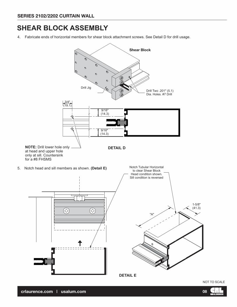
NOTE: Drill lower hole only at head and upper hole only at sill. Countersink for a #8 FHSMS
Drill Two .201" (5.1) Dia. Holes. #7 Drill
3/4"(19.1)
9/16"(14.3)
9/16"(14.3)
SHEAR BLOCK ASSEMBLY4. Fabricate ends of horizontal members for shear block attachment screws. See Detail D for drill usage.
Drill Jig
Notch Tubular Horizontal to clear Shear Block
Head condition shown.Sill condition is reversed
1-5/8" (41.3)
"A"
5. Notch head and sill members as shown. (Detail E)
Shear Block
DETAIL D
DETAIL E
SERIES 2102/2202 CURTAIN WALL
ALUMINUM09crlaurence.com | usalum.com
NOT TO SCALE
Shear Block
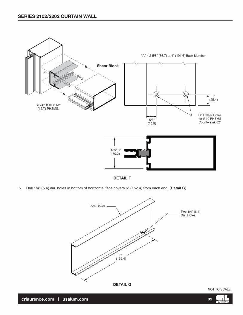
"A" = 2-5/8" (66.7) at 4" (101.6) Back Member
6. Drill 1/4" (6.4) dia. holes in bottom of horizontal face covers 6" (152.4) from each end. (Detail G)
Two 1/4" (6.4) Dia. Holes
6"(152.4)
Face Cover
ST242 # 10 x 1/2" (12.7) PHSMS.
1-3/16" (30.2)
5/8"(15.9)
1"(25.4)
Drill Clear Holesfor # 10 FHSMSCountersink 82°
DETAIL F
DETAIL G
SERIES 2102/2202 CURTAIN WALL
ALUMINUM10crlaurence.com | usalum.com
NOT TO SCALE
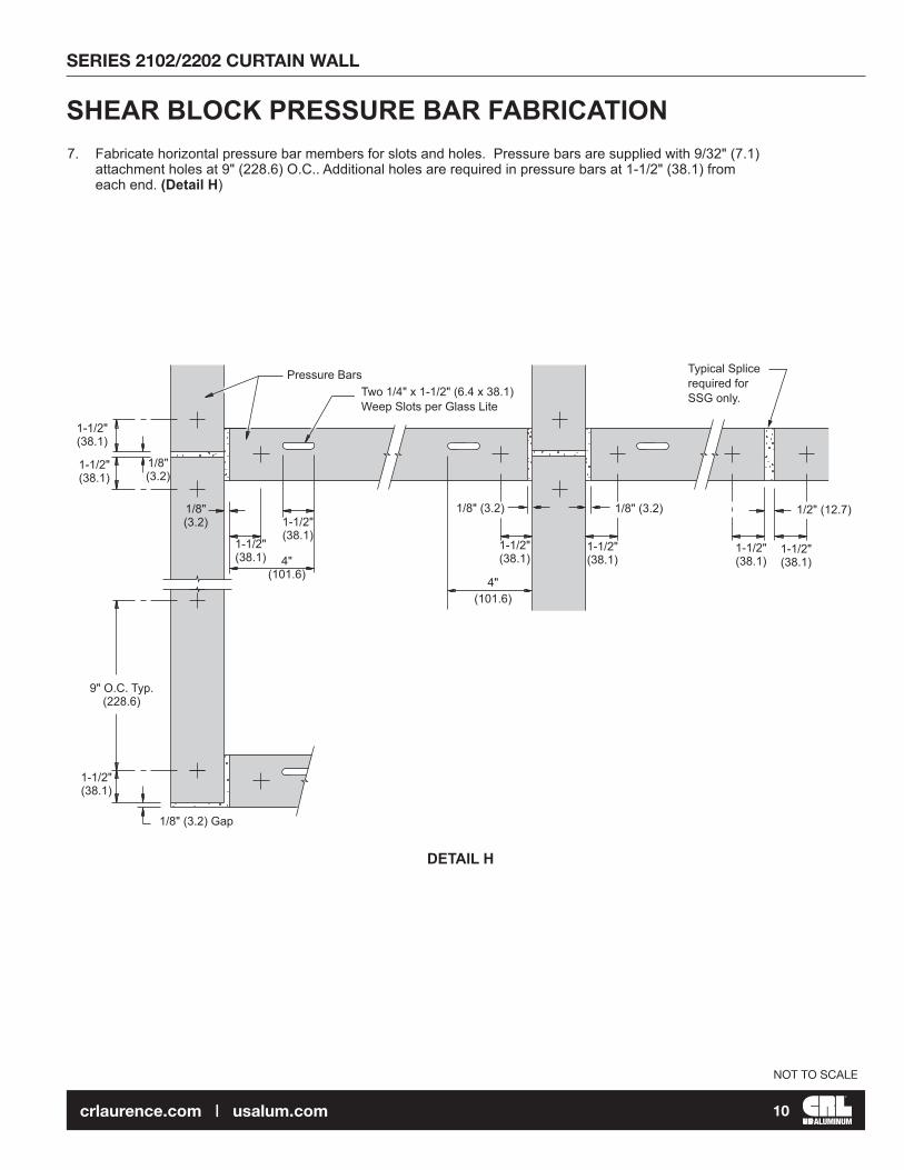
7. Fabricate horizontal pressure bar members for slots and holes. Pressure bars are supplied with 9/32" (7.1) attachment holes at 9" (228.6) O.C.. Additional holes are required in pressure bars at 1-1/2" (38.1) from each end. (Detail H)
SHEAR BLOCK PRESSURE BAR FABRICATION
9" O.C. Typ.(228.6)
1-1/2"(38.1)
1/8"(3.2)
1-1/2"(38.1)
1-1/2"(38.1)
1-1/2"(38.1)
1-1/2"(38.1)
1-1/2"(38.1)
1/8"(3.2)
1/8" (3.2) Gap
Typical Splicerequired forSSG only.Two 1/4" x 1-1/2" (6.4 x 38.1)
Weep Slots per Glass Lite
Pressure Bars
1-1/2"(38.1)
1/2" (12.7)
4"(101.6)
1-1/2"(38.1)
1-1/2"(38.1)
4"(101.6)
1/8" (3.2)1/8" (3.2)
DETAIL H
SERIES 2102/2202 CURTAIN WALL
ALUMINUM11crlaurence.com | usalum.com
NOT TO SCALE
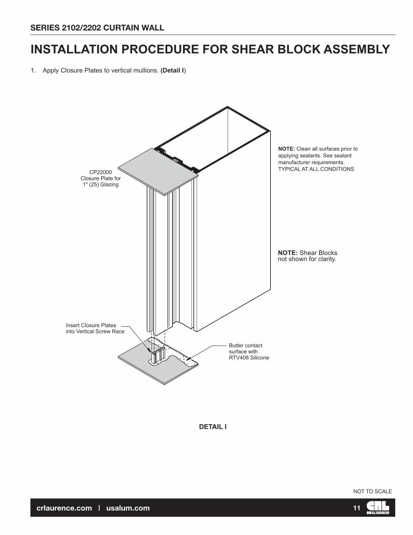
NOTE: Clean all surfaces prior to applying sealants. See sealant manufacturer requirements. TYPICAL AT ALL CONDITIONS
NOTE: Shear Blocks not shown for clarity.
CP22000Closure Plate for 1" (25) Glazing
Insert Closure Plates into Vertical Screw Race
1. Apply Closure Plates to vertical mullions. (Detail I)
INSTALLATION PROCEDURE FOR SHEAR BLOCK ASSEMBLY
Butter contact surface with RTV408 Silicone
DETAIL I

SERIES 2102/2202 CURTAIN WALL
ALUMINUM12crlaurence.com | usalum.com
NOT TO SCALE
NOTE: Shear Blocks not shown for clarity.
2. Slide anchors into ends of vertical mullions (Detail J). If shims are required place them directly under each side of vertical for proper load distribution. Secure anchors to structure plumb, level, and true. See approved shop drawings for anchor bolt type and size.
INSTALLATION PROCEDURE FOR SHEAR BLOCK ASSEMBLY
3. Attach Shear Blocks to verticals with screws provided.
NOTE: Tubular intermediate horizontals must be installed per bay along with verticals. Head and sill members are notched. Last bay intermediate horizontal is notched. (See Page 08)
UseAPK204 for PT204
(2) #10 x 1/2" (12.7) PHSMS (Included)
NOTE: Aluminum anchors must be isolated from dissimilar materials. Typical at top and bottom.
Top and Bottom "T" Anchors
Shim both sides
Field prepare per job conditions and loading. Two Bolts at each Anchor minimum
"T" Anchor at Wall Jamb Condition (two bolts minimum). Typical at top and bottom
DETAIL J
DETAIL K

SERIES 2102/2202 CURTAIN WALL
ALUMINUM13crlaurence.com | usalum.com
NOT TO SCALE
ASSEMBLY PROCEDURE
1. Attach shear blocks to mullion and jambs. (Detail L)
INSTALLATION PROCEDURE FOR PRE-ASSEMBLED MULTI-LITE ASSEMBLY
2. Assemble frame. (Detail M)
DETAIL L
DETAIL M
(2) #10 x 1/2" (12.7) PHSMS (Included)
SERIES 2102/2202 CURTAIN WALL
ALUMINUM14crlaurence.com | usalum.com
NOT TO SCALE
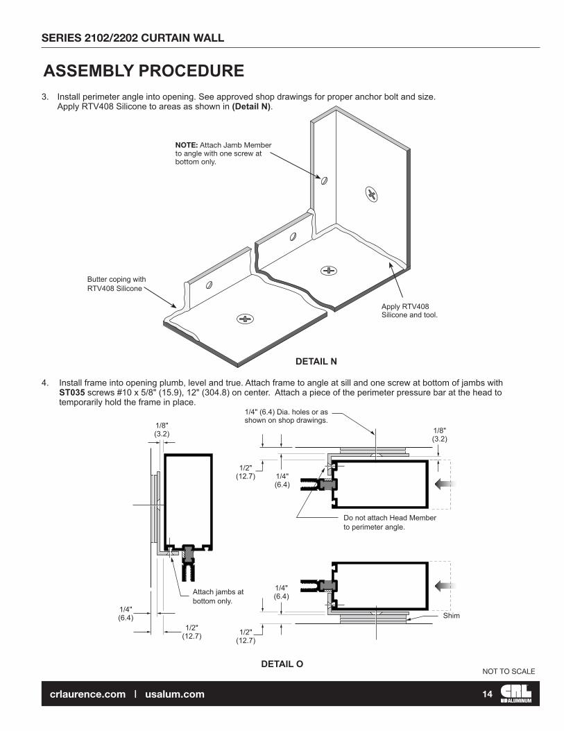
Butter coping with RTV408 Silicone
Apply RTV408 Silicone and tool.
1/8" (3.2)
1/4" (6.4)
1/2" (12.7)
1/4" (6.4)
1/4" (6.4)
1/2" (12.7)
1/4" (6.4) Dia. holes or as shown on shop drawings.
Do not attach Head Member to perimeter angle.
Shim
1/2" (12.7)
1/8" (3.2)
Attach jambs at bottom only.
ASSEMBLY PROCEDURE3. Install perimeter angle into opening. See approved shop drawings for proper anchor bolt and size. Apply RTV408 Silicone to areas as shown in (Detail N).
4. Install frame into opening plumb, level and true. Attach frame to angle at sill and one screw at bottom of jambs with ST035 screws #10 x 5/8" (15.9), 12" (304.8) on center. Attach a piece of the perimeter pressure bar at the head to temporarily hold the frame in place.
NOTE: Attach Jamb Member to angle with one screw at bottom only.
DETAIL N
DETAIL O

SERIES 2102/2202 CURTAIN WALL
ALUMINUM15crlaurence.com | usalum.com
NOT TO SCALE
CRITICAL SEAL Seal over head of Screws with RTV408 Silicone.
Apply RTV408 Silicone as shown filling Gasket Reglets and Vertical Grooves.
CRITICAL SEAL Apply RTV408 Silicone to three contact areas of Intermediate Dams prior to installation.
NOTE: Consult sealant manufacturer for proper cleaning and priming recommendations.
CRITICAL SEAL Apply RTV408 Silicone to three contact areas of End Dams prior to installation.
CRITICAL SEAL Fill with RTV408 Silicone, portion of Gasket Reglet just behind the End Dam.
CRITICAL SEAL Apply RTV408 Silicone and seal all Horizontal to Vertical Joints.
FRAME SEALANT PROCEDURE
1. Apply RTV408 Silicone and seal joint at horizontal and vertical intersection. Seal over heads of screws in the glazing pockets (Detail P).2. Apply RTV408 Silicone at the three contact areas of end dams. Fill the vertical gasket reglet with RTV408 Silicone at the end dam location.3. Slide end dams into place. NOTE: End dams occur at head and sill also.
PT204
CW265
PT204
DETAIL P
SERIES 2102/2202 CURTAIN WALL
ALUMINUM16crlaurence.com | usalum.com
NOT TO SCALE
1/2" (12.7)
1/2" (12.7)
1/2" (12.7) 1/2"
(12.7)1/2"
(12.7)1/2"
(12.7)
3/8" (9.5)
13/16" (20.6)
13/16" (20.6)
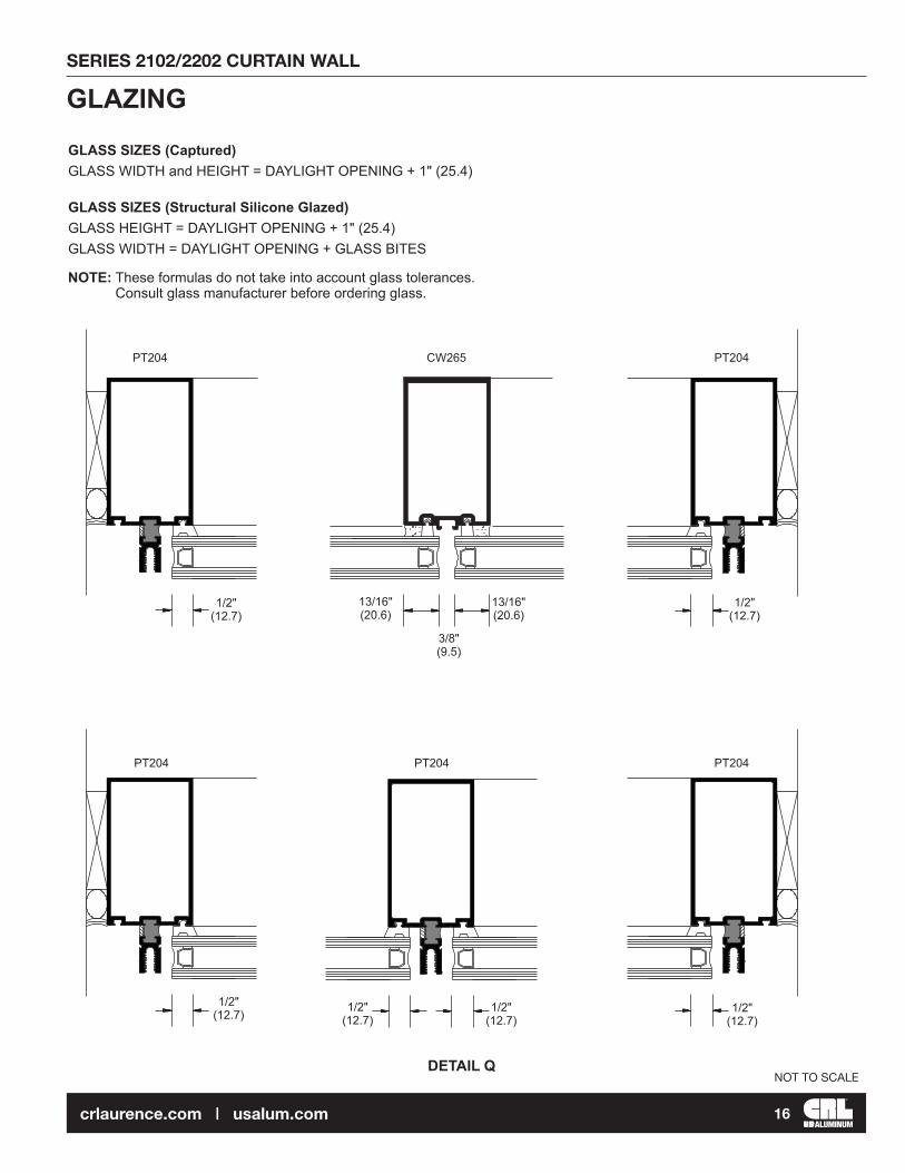
GLAZING
NOTE: These formulas do not take into account glass tolerances. Consult glass manufacturer before ordering glass.
GLASS SIZES (Captured) GLASS WIDTH and HEIGHT = DAYLIGHT OPENING + 1" (25.4) GLASS SIZES (Structural Silicone Glazed) GLASS HEIGHT = DAYLIGHT OPENING + 1" (25.4) GLASS WIDTH = DAYLIGHT OPENING + GLASS BITES
PT204 PT204PT204
PT204CW265PT204
DETAIL Q
SERIES 2102/2202 CURTAIN WALL
ALUMINUM17crlaurence.com | usalum.com
NOT TO SCALE
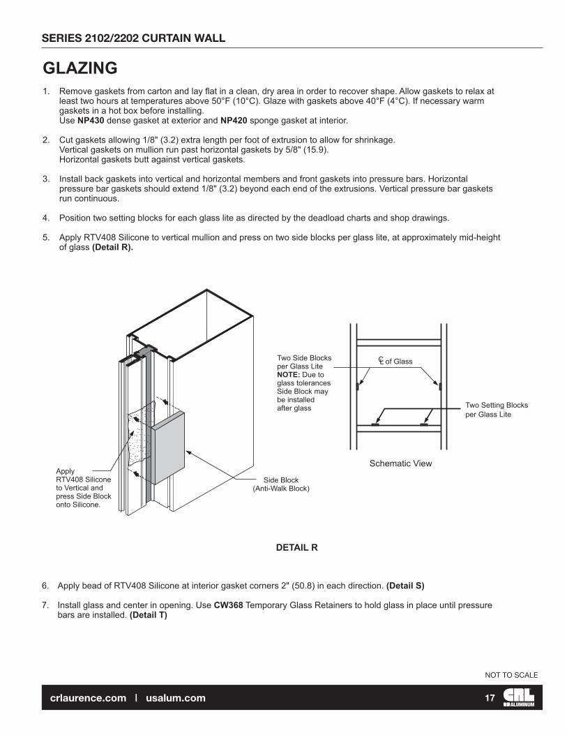
Side Block(Anti-Walk Block)
Two Side Blocks per Glass Lite NOTE: Due to glass tolerances Side Block may be installed after glass
Apply RTV408 Silicone to Vertical and press Side Block onto Silicone.
Two Setting Blocksper Glass Lite
of GlassCL
Schematic View
1. Remove gaskets from carton and lay flat in a clean, dry area in order to recover shape. Allow gaskets to relax at least two hours at temperatures above 50°F (10°C). Glaze with gaskets above 40°F (4°C). If necessary warm gaskets in a hot box before installing. Use NP430 dense gasket at exterior and NP420 sponge gasket at interior.
2. Cut gaskets allowing 1/8" (3.2) extra length per foot of extrusion to allow for shrinkage. Vertical gaskets on mullion run past horizontal gaskets by 5/8" (15.9). Horizontal gaskets butt against vertical gaskets.
3. Install back gaskets into vertical and horizontal members and front gaskets into pressure bars. Horizontal pressure bar gaskets should extend 1/8" (3.2) beyond each end of the extrusions. Vertical pressure bar gaskets run continuous.
4. Position two setting blocks for each glass lite as directed by the deadload charts and shop drawings.
5. Apply RTV408 Silicone to vertical mullion and press on two side blocks per glass lite, at approximately mid-height of glass (Detail R).
GLAZING
6. Apply bead of RTV408 Silicone at interior gasket corners 2" (50.8) in each direction. (Detail S)
7. Install glass and center in opening. Use CW368 Temporary Glass Retainers to hold glass in place until pressure bars are installed. (Detail T)
DETAIL R

SERIES 2102/2202 CURTAIN WALL
ALUMINUM18crlaurence.com | usalum.com
NOT TO SCALE
NOTE:Vertical Gaskets do not run through to allow for End and Intermediate Dams installation.They extend approximately 5/8" (15.9) past edge of the Horizontal.
Apply RTV408 Silicone to Interior Gaskets corner 2” (50.8) on each direction
Apply RTV408 Silicone over heads of screws
Tool Sealant
Fill void between Gaskets with RTV408 Silicone
2" (50.8)
2" (50.8)
5/8" (15.9)
RG635 Temporary Glass Retainer
CW368 Temporary Glass Retainer. Torque to 30 in. Pound (3.4 Nm) NOTE: Do Not Over Torque Glass Retainers Bolts. Use one Retainer per each 150 lbs. (667.2 N) of load. (I.e. if glass height x glass width x windload = 350 lbs. use three retainers)
8. Structural silicone is applied from the interior. Follow silicone manufacturer’s instructions and recommendations for surface preparation and silicone application. Mask glass and aluminum and tool sealant.
9. After structural silicone has fully cured remove temporary glass retainers from intermediate verticals; insert open cell polyurethane rod between glass edges; mask glass adjacent to joint, and apply outside weatherseal.
GLAZING STRUCTURAL SILICONE APPLICATION
DETAIL S
DETAIL T
SERIES 2102/2202 CURTAIN WALL
ALUMINUM19crlaurence.com | usalum.com
NOT TO SCALE
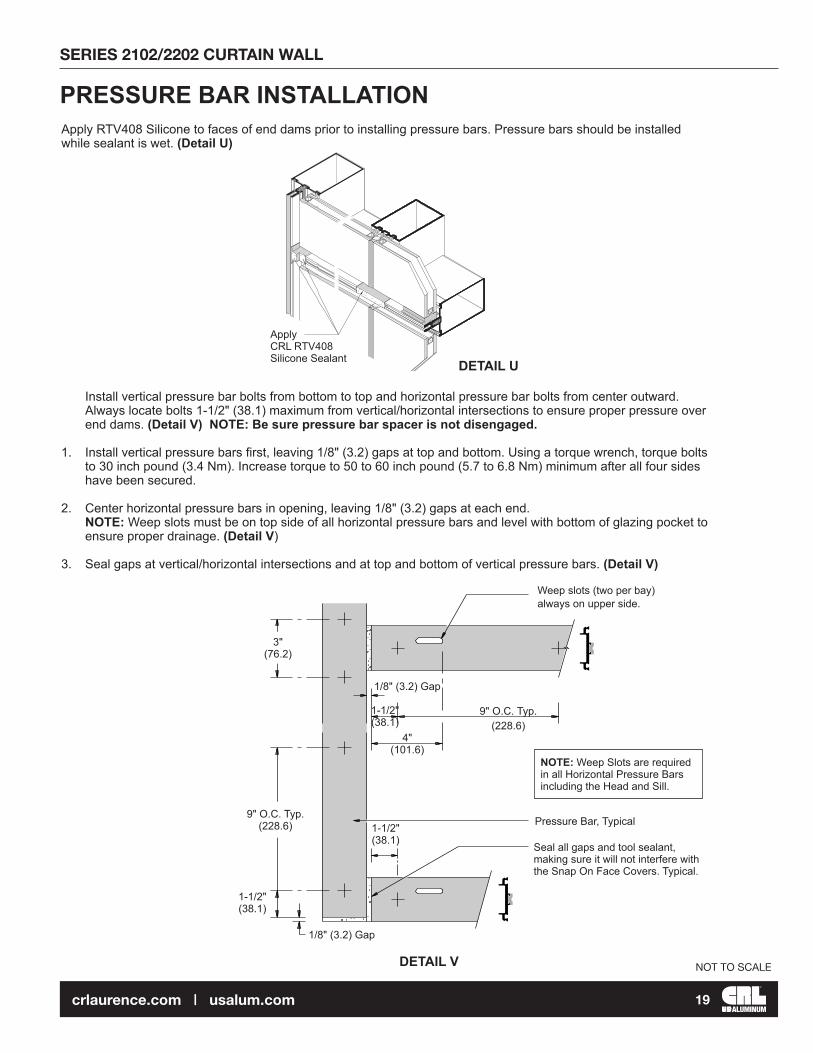
Install vertical pressure bar bolts from bottom to top and horizontal pressure bar bolts from center outward. Always locate bolts 1-1/2" (38.1) maximum from vertical/horizontal intersections to ensure proper pressure over end dams. (Detail V) NOTE: Be sure pressure bar spacer is not disengaged.
1. Install vertical pressure bars first, leaving 1/8" (3.2) gaps at top and bottom. Using a torque wrench, torque bolts to 30 inch pound (3.4 Nm). Increase torque to 50 to 60 inch pound (5.7 to 6.8 Nm) minimum after all four sides have been secured.
2. Center horizontal pressure bars in opening, leaving 1/8" (3.2) gaps at each end. NOTE: Weep slots must be on top side of all horizontal pressure bars and level with bottom of glazing pocket to ensure proper drainage. (Detail V)
3. Seal gaps at vertical/horizontal intersections and at top and bottom of vertical pressure bars. (Detail V)
Apply CRL RTV408 Silicone Sealant
Apply RTV408 Silicone to faces of end dams prior to installing pressure bars. Pressure bars should be installed while sealant is wet. (Detail U)
PRESSURE BAR INSTALLATION
Weep slots (two per bay) always on upper side.
Pressure Bar, Typical
Seal all gaps and tool sealant, making sure it will not interfere with the Snap On Face Covers. Typical.
3" (76.2)
9" O.C. Typ.(228.6)
1-1/2"(38.1)
1/8" (3.2) Gap
1-1/2"(38.1)
1-1/2"(38.1)
1/8" (3.2) Gap
9" O.C. Typ.(228.6)
NOTE: Weep Slots are required in all Horizontal Pressure Bars including the Head and Sill.
4"(101.6)
DETAIL U
DETAIL V
SERIES 2102/2202 CURTAIN WALL
ALUMINUM20crlaurence.com | usalum.com
NOT TO SCALE
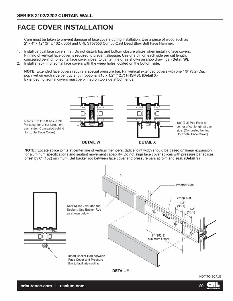
1/16" x 1/2" (1.6 x 12.7) Roll Pin at center of cut length on each side. (Concealed behind Horizontal Face Cover)
1/8" (3.2) Pop Rivet at center of cut length at each side. (Concealed behind Horizontal Face Cover)
Seal Splice Joint and tool Sealant. Use Backer Rod as shown below
Insert Backer Rod between Face Cover and Pressure Bar to facilitate sealing
1-1/2"(38.1)
1-1/2"(38.1)
Weep Slot
Weather Seal
6" (152.4) Minimum Offset
Care must be taken to prevent damage of face covers during installation. Use a piece of wood such as 2" x 4" x 12" (51 x 102 x 305) and CRL ST57550 Compo-Cast Dead Blow Soft Face Hammer.
1. Install vertical face covers first. Do not disturb top and bottom closure plates when installing face covers. Pinning of vertical face cover is required to prevent slippage. Use one pin on each side per cut length, concealed behind horizontal face cover closer to center line or as shown on shop drawings. (Detail W). 2. Install snap-in horizontal face covers with the weep holes located on the bottom side.
NOTE: Extended face covers require a special pressure bar. Pin vertical extended covers with one 1/8" (3.2) Dia. pop rivet on each side per cut length (optional #10 x 1/2" (12.7) FHSMS). (Detail X) Extended horizontal covers must be pinned on top side at both ends.
FACE COVER INSTALLATION
NOTE: Locate splice joints at center line of vertical members. Splice joint width should be based on linear expansion for aluminum specifications and sealant movement capability. Do not align face cover splices with pressure bar splices; offset by 6" (152) minimum. Set backer rod between face cover and pressure bars at joint and seal. (Detail Y)
DETAIL W DETAIL X
DETAIL Y

SERIES 2102/2202 CURTAIN WALL
ALUMINUM21crlaurence.com | usalum.com
NOT TO SCALE
Vertical Adapter runs through
NOTE: Discontinue Vertical Adapters at Splice Joints
Secure Butt Glazing Adapters with #10 x 1" FHSS Screws 1-1/2" (38.1) from ends and 24" (609.6) O.C. maximum.
Fill Gasket Reglet with RTV 408 Silicone before installing Adapters (This is a continuous seal)
Seal Horizontal/Vertical Joint and tool Sealant.
D.L.O.-1/8" (3.2)
D.L.O.
D.L
.O. +
1" (
25.4
)
D.L
.O.
Horizontal Adapter
TRANSITION GLAZING1. Apply RTV408 Silicone into gasket reglets before installing snap-in transition adapters.
2. Install vertical adapters first.
3. Install horizontal adapters and seal horizontal/vertical joints. Tool sealant. (Detail Z)
DETAIL Z

SERIES 2102/2202 CURTAIN WALL
ALUMINUM22crlaurence.com | usalum.com
NOT TO SCALE
Linear expansion for aluminum, in inches = Length (") x F° difference in temperature x .0000129Linear expansion for aluminum, in millimeters = Length (mm) x C° difference in temperature x .0232
Splice Sleeve
Tape to hold Sleeve in retracted position
Apply CRL 827T2 Bond Breaker Tape to Sleeve at Joint Area
Splice joint width should be based on sealant movement capability and on the following formula:
VERTICAL SPLICE JOINTS
A 1/2" (12.7) minimum joint is recommended. Use a 1/2" (12.7) spacer shim to set and hold the mullion joint constant during erection. Remove the shim after attaching the verticals to the anchors. Splice joints must occur at spandrel areas. NOTE: Splice joints are designed to accommodate thermal movement only. They do not compensate for variations in floor levels.
1. Clean splice sleeves and all joint surfaces. Apply bond breaker tape to areas where sleeve will be sealed to avoid three side adhesion. (Detail AA)
2. Slide sleeve into the upper member before it is installed and tape to hold it in retracted position. (Detail AA)
3. Install stop screw, 2-3/4" (69.9) down from top of extrusion at inside of lower member. (Detail BB)
4. Install upper member and let extruded sleeve slide down until it sits on top of stop screw.
5. Seal joint over sleeve. (Detail CC) When transition adapters for 1/4" (6.4) spandrel are used they should be discontinued at splice joint and installed after splice joint is sealed. Stagger joints on back members, pressure bars and face caps. (Detail BB)
6. Seal pressure bar joint. (Detail CC)
7. Install face covers and seal joint using backer rod as required. (Detail CC)
DETAIL AA

SERIES 2102/2202 CURTAIN WALL
ALUMINUM23crlaurence.com | usalum.com
NOT TO SCALE
4" (101.6)
1/2" (12.7) Face Cover Splice Joint
1-1/2" (38.1)
1-1/2" (38.1)
2-3/4" (69.9)1/2" (12.7)
Pressure Bar Splice
1/2" (12.7) min. Splice Joint Width
Use Backer Rod to facilitate Face Cover Seal
Splice Sleeve
Bond Breaker Tape
Seal Face Cover Joint and tool (Use Backer Rod as required)
Stop Screw
Apply CRL 827T2 Bond Breaker Tape
Seal and tool joint
Seal Pressure Bar Joint
1" (25.4)
DETAIL CC
DETAIL BB

SERIES 2102/2202 CURTAIN WALL
ALUMINUM24crlaurence.com | usalum.com
NOT TO SCALE
MULTI-SPAN CONDITIONDetail DD and Detail EE show fixed (deadload) and expansion (windload) anchors. Anchor type and size vary per job requirements. Details shown are to be used as a guide only. See approved shop drawings for actual conditions.
Secure verticals to anchor clips after alignment has been completed.
NOTE: Mullion spacing must be held to within +1/32" (0.8). Check overall frame dimension every four bays to monitor dimension build up.
Drill holes after alignment has been completed.
AP360Nylatron Pad
Primary Bolts with Nuts Flat Washer, and Lock Washer
1-1/2" min.(38.1)
1-1/2" min.(38.1)
Drill Holes after alignmenthas been completed.
AP360Nylatron Pad
Primary Bolts with Nuts,Flat Washer, and Lock WasherBack off Nut 1/4 turn aftertightening to allow forthermal movement.
Fixed (Deadload) Anchor
Expansion (Windload) Anchor
DETAIL EE
DETAIL DD
SERIES 2102/2202 CURTAIN WALL
ALUMINUM25crlaurence.com | usalum.com
NOT TO SCALE
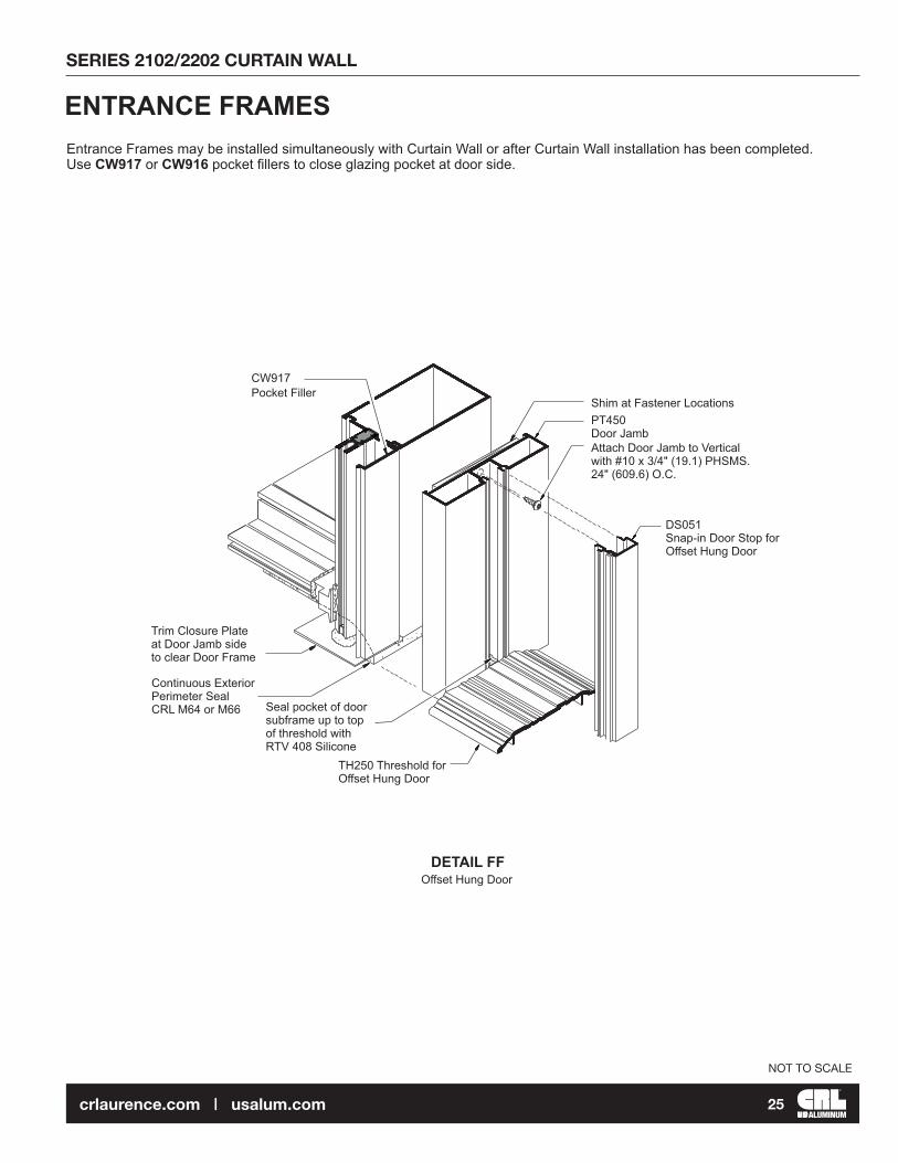
Shim at Fastener LocationsPT450 Door JambAttach Door Jamb to Vertical with #10 x 3/4" (19.1) PHSMS. 24" (609.6) O.C.
Trim Closure Plate at Door Jamb side to clear Door Frame
Continuous Exterior Perimeter Seal CRL M64 or M66
Offset Hung Door
TH250 Threshold for Offset Hung Door
DS051 Snap-in Door Stop for Offset Hung Door
CW917 Pocket Filler
Seal pocket of door subframe up to top of threshold with RTV 408 Silicone
ENTRANCE FRAMESEntrance Frames may be installed simultaneously with Curtain Wall or after Curtain Wall installation has been completed.Use CW917 or CW916 pocket fillers to close glazing pocket at door side.
DETAIL FF

SERIES 2102/2202 CURTAIN WALL
ALUMINUM26crlaurence.com | usalum.com
NOT TO SCALE
CW207Header Adaptor Length = DOOR OPENING WIDTH Minus 1/32" (0.8). Jamb Adaptor Length = DOOR OPENING HEIGHT Plus 7/16" (11.1).
CW206Header Cap Length = DOOR OPENING WIDTH Minus 1/32" (0.8). Jamb Cap Length = DOOR OPENING HEIGHT Plus 7/16" (11.1). (Field cutting may be required to obtain a tight joint with vertical cap above)
CW209Header Door Stop Length = DOOR OPENING WIDTH Minus 1/32" (0.8). Jamb Door Stop Length = DOOR OPENING HEIGHT Minus 1-1/32" (26.2).
9" O.C. (Typ.)(228.6)
1-1/2"(38.1)
1-1/2"(38.1)
CW207
Isolator
Holes centered on groove
5/16" (7.9) Dia. holes
NOTE: Flush door adaptors are not available for Series 2100 butt glaze applications
FLUSH DOOR ADAPTOR FABRICATION AND INSTALLATION
1. Cut door adaptor members to length.
2. Drill 5/16" (7.9) diameter anchor holes in all cut to length adaptors 1-1/2" (38.1) from each end and 9" (228.6) O.C. (Detail GG). NOTE: Isolator must be in place prior to drilling anchor holes.
FABRICATION
DETAIL GG
SERIES 2102/2202 CURTAIN WALL
ALUMINUM27crlaurence.com | usalum.com
NOT TO SCALE
CW207
CW206
1-1/2"(38.1)
1-1/2"(38.1)
9" O.C. (Typ.)(228.6)
1/4"(6.4) 1-3/16"
(30.2)
1/16"(1.6)
1-1/2"(38.1)
1-1/2"(38.1)
11/64" (4.4) Dia. Holeor #16 Drill Bit
Drill and Countersink for 1/4"-20 FHMS
5/8"(15.9)
7/16"(11.1)
1-5/32"(29.4)
5/32"(11.9) Weep Slots Anchor Hole
3/16"(4.8)
4"(101.6)
27/32"(21.4)
4"(101.6)
DOOR OPENING WIDTH Minus 1/32" (.8)
DOOR OPENING WIDTH Minus 1/32" (.8)
9" O.C. (Typ.)(228.6)
1-1/2"(38.1)
CW207 1-1/2"(38.1)
4"(101.6)
4"(101.6)
Weep Slots Anchor Hole
1-1/2"(38.1)
1-1/2"(38.1)
11/64" (4.4) Dia. Holeor #16 Drill Bit
3/16"(4.8)
CL
CL
FLUSH DOOR ADAPTOR FABRICATION AND INSTALLATION
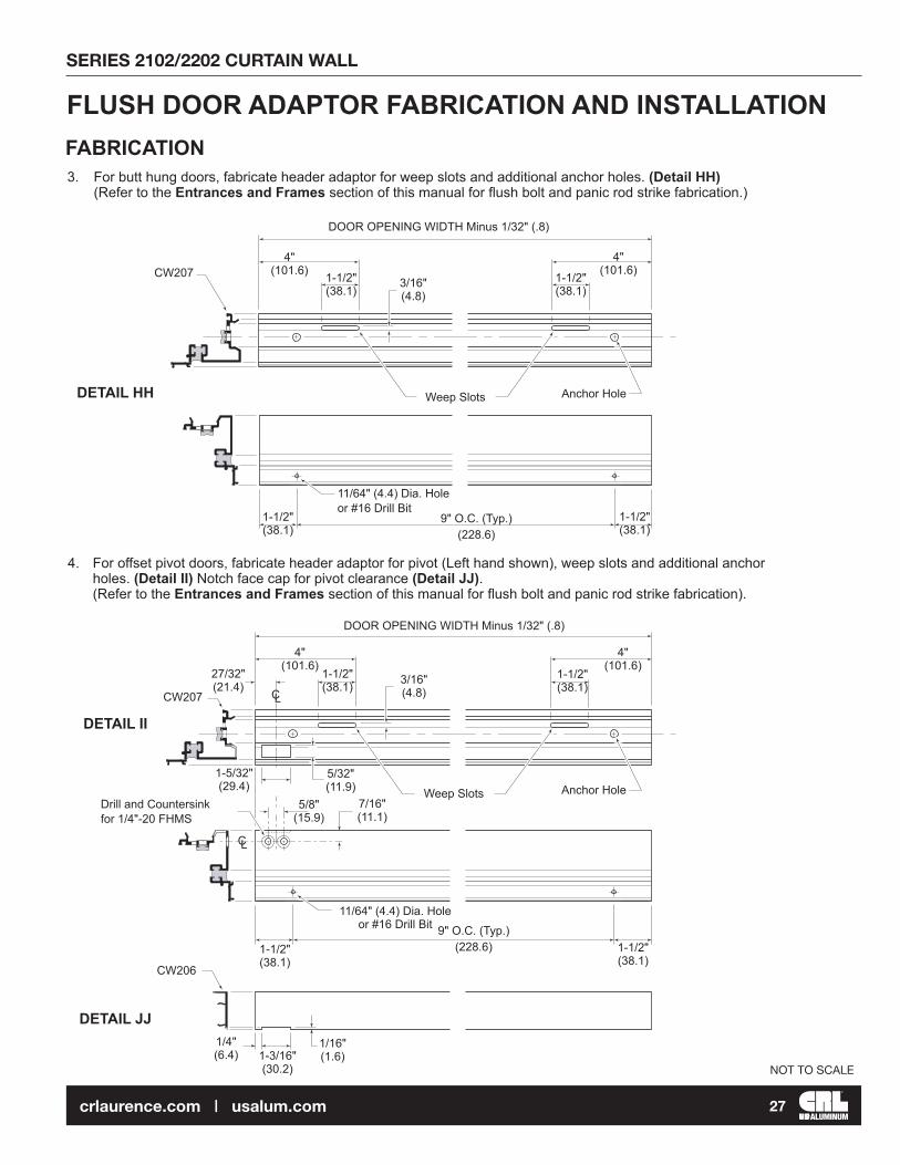
3. For butt hung doors, fabricate header adaptor for weep slots and additional anchor holes. (Detail HH) (Refer to the Entrances and Frames section of this manual for flush bolt and panic rod strike fabrication.)
4. For offset pivot doors, fabricate header adaptor for pivot (Left hand shown), weep slots and additional anchor holes. (Detail II) Notch face cap for pivot clearance (Detail JJ). (Refer to the Entrances and Frames section of this manual for flush bolt and panic rod strike fabrication).
FABRICATION
DETAIL II
DETAIL HH
DETAIL JJ
SERIES 2102/2202 CURTAIN WALL
ALUMINUM28crlaurence.com | usalum.com
NOT TO SCALE
11/64" (4.4) Dia. Hole or #16 Drill Bit Locate 9" (228.6) O.C.
9" O.C. (Typ.) (228.6)
1-1/2"(38.1)
1/8"(3.2)
5/32" R.(3.9)
3/8"(9.5)
1"(25.4)
1-1/4"(31.8)
9-11/16"(246.1)
1-1/16"(27)
4-17/32"(115.1)
7/16"(11.1)
DO
OR
OP
EN
ING
HE
IGH
T P
lus
7/16
" (11
.1)
1-5/32"(29.4)
15/64"(5.9)
.134"(3.4)
9" O.C. (Typ.)(228.6)
1-1/2"(38.1)
21/64"(8.3)
25/32"(19.8)
7/16"(11.1)
1-7/16"(36.5)
1-1/16"(27)
2-17/64"(57.5)
EQ
UA
LE
QU
AL
6-11/16"(169.9)
1-1/4"(31.8)
2-17/64"(57.5)
11/64" (4.4) Dia. Holeor #16 Drill Bit
DO
OR
OP
EN
ING
HE
IGH
T P
lus
9/16
" (14
.3)
9" O.C. (Typ.)(228.6)
1-1/2"(38.1)
1"(25.4)
1/8 "(3.2)
1-1/4"(31.8)
7/16"(11.1)
1-1/16"(27)
25/32"(19.8)
21/64"(8.3)
3/8"(9.5)
30-1/2"(774.7)
1/2"(12.7)13/16"(20.6)
1-5/16"(34)
11/16"(17.5)
.125" R.(3.2)
1-1/2"(38.1)
1-9/32"(32.5)
15/64"(5.9)
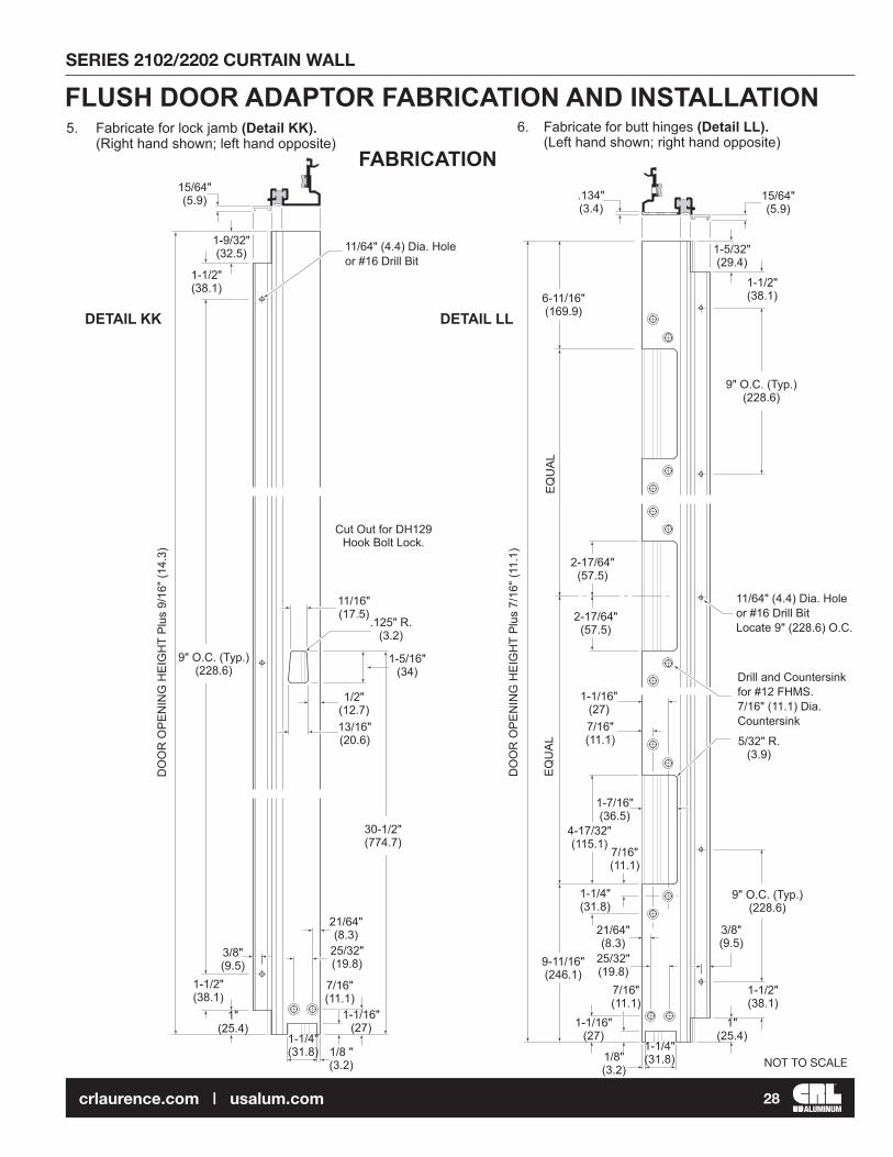
Cut Out for DH129Hook Bolt Lock.
FLUSH DOOR ADAPTOR FABRICATION AND INSTALLATION5. Fabricate for lock jamb (Detail KK). (Right hand shown; left hand opposite)
FABRICATION6. Fabricate for butt hinges (Detail LL). (Left hand shown; right hand opposite)
Drill and Countersink for #12 FHMS. 7/16" (11.1) Dia. Countersink
DETAIL LLDETAIL KK
7/16"(11.1)
SERIES 2102/2202 CURTAIN WALL
ALUMINUM29crlaurence.com | usalum.com
NOT TO SCALE
Drill and Countersink for #12 FHMS 7/16" (11.1) Dia. Countersink
11/64" (4.4) Dia. Holeor #16 Drill Bit
1/2"(12.7)
3/8"(9.5)
3/8"(9.5)11/32"
(8.7)
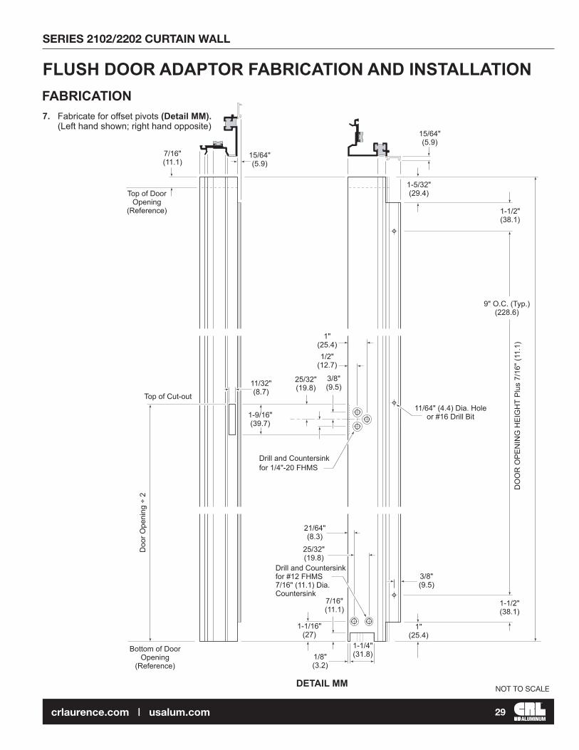
FLUSH DOOR ADAPTOR FABRICATION AND INSTALLATION
7. Fabricate for offset pivots (Detail MM). (Left hand shown; right hand opposite)
FABRICATION
DO
OR
OP
EN
ING
HE
IGH
T P
lus
7/16
" (11
.1)
Top of Cut-out
9" O.C. (Typ.)(228.6)
1-1/2"(38.1)
1"(25.4)
1-5/32"(29.4)
15/64"(5.9)
1-1/2"(38.1)
21/64"(8.3)
25/32"(19.8)
7/16"(11.1)
1"(25.4)
25/32"(19.8)
15/64"(5.9)
Top of Door Opening
(Reference)
1/8"(3.2)
1-1/4"(31.8)
1-1/16"(27)
1-9/16"(39.7)
Doo
r Ope
ning
÷ 2
Bottom of Door Opening
(Reference)
Drill and Countersink for 1/4"-20 FHMS
DETAIL MM
7/16"(11.1)

SERIES 2102/2202 CURTAIN WALL
ALUMINUM30crlaurence.com | usalum.com
NOT TO SCALE
MS222Pressure Bar Screw
AV9605#8-18 x 1/2" (12.7) PH Tek
(4) #12-24 x 1/2" (12.7) (Included)
BP459Backup Plate
TC500 Anchor Clip (Supplied with Door Hardware)
0P400 Frame Portion Bottom Pivot (Supplied with Door Hardware)
FLUSH DOOR ADAPTOR FABRICATION AND INSTALLATION
8. For butt hung application, install hinge back up plates and threshold clips. (Detail NN and Detail OO) For offset pivot application, install bottom frame portion pivot(s). (Detail PP) Single doors require threshold clip at lock jamb. (Detail OO)
9. Install gaskets in door adaptors.
FABRICATION
NOTE: Prior to adaptor installation all End Dams must be installed and sealed. Transom and sidelite glass must be in place.
1. Seal face of end dams. (Detail QQ)
2. Install jamb and head adaptors using MS222 pressure bar screws. (Detail QQ) Refer to page 24 of the glazing portion of this section for bolt tightening procedures. Vertical adaptors extend from floor to 7/16" (11.11) above bottom of door header/horizontal and must be installed prior to head adaptor installation.
3. Secure adaptors to mullion side walls with AV9605 Pan Head Phillips tek screws. (Detail QQ)
Cover Face of End Dams with RTV408 Silicone
INSTALLATION
These hardware items must be applied prior to door adaptor installation.
DETAIL OO DETAIL PP
DETAIL QQ
DETAIL NN
(2) #12-24 x 1/2" (12.7) (Included)
(2) #12-24 x 1/2" (12.7) (Included)

SERIES 2102/2202 CURTAIN WALL
ALUMINUM31crlaurence.com | usalum.com
NOT TO SCALE
FLUSH DOOR ADAPTOR FABRICATION AND INSTALLATION4. Seal all pressure bar bolt heads. (Detail RR)
5. Seal gaps at intersections of pressure bars and door adaptors.
6. Install thresholds into opening using screws provided with door hardware. (Detail SS for butt hung, Detail TT for offset pivot application).
(2) MS176 #12-24 x 3/8" (9.5) FH Screws
0P400Frame Portion Bottom Pivot
Attach Threshold to Clips with (2) MS176 #12-24 x 3/8" (9.5) FH Screws.
Threshold Clip
Apply RTV408 Silicone to Seal Pressure Bar and Bolt Heads
Seal intersecting Pressure Bar and Adaptor Joints
DETAIL SS
DETAIL RR
DETAIL TT
PT204
PT204
PT204PT204
NOTE: THIS IS A CRITICAL SEAL.

SERIES 2102/2202 CURTAIN WALL
ALUMINUM32crlaurence.com | usalum.com
NOT TO SCALE
(3) #12-24 x 1/2" (12.7) Included
(2) 1/4-20 x 1/2" (12.7) Included
FLUSH DOOR ADAPTOR FABRICATION AND INSTALLATION
7. Snap on face caps (Detail UU). Vertical face caps run from floor to 9/16" (14.3) above bottom of header. (Field cutting to length is recommended)
8. Snap door stop on header adaptor (Detail UU). (Head door stop runs through)
9. Snap door stops on jamb members (Detail UU).
INSTALLATION
10. For offset pivot doors, install frame portion pivots (Detail WW).
D062(Frame Head Portion)
DH022(Frame Portion)
Door Stop
Face CapDETAIL UU
DETAIL WW
SERIES 2102/2202 CURTAIN WALL
ALUMINUM33crlaurence.com | usalum.com
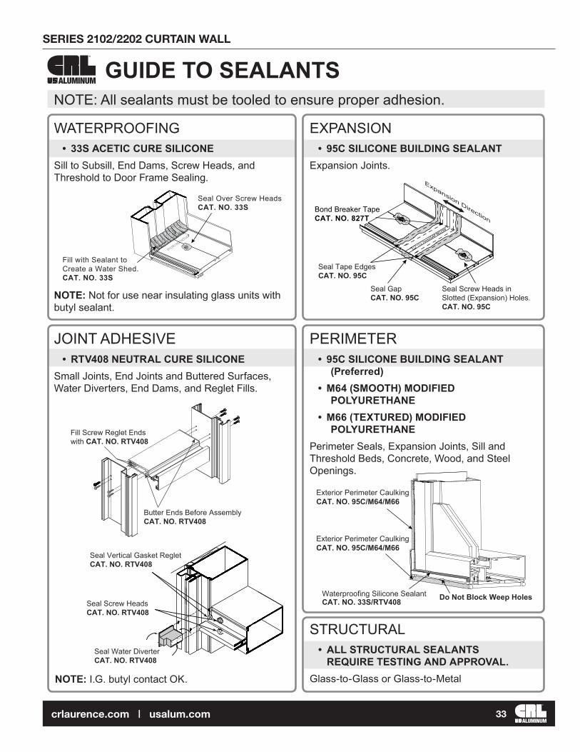
GUIDE TO SEALANTSALUMINUM
NOTE: I.G. butyl contact OK.
NOTE: Not for use near insulating glass units with butyl sealant.
PERIMETER• 95C SILICONE BUILDING SEALANT
(Preferred)• M64 (SMOOTH) MODIFIED
POLYURETHANE • M66 (TEXTURED) MODIFIED
POLYURETHANE Perimeter Seals, Expansion Joints, Sill and Threshold Beds, Concrete, Wood, and Steel Openings.
WATERPROOFING• 33S ACETIC CURE SILICONE
Sill to Subsill, End Dams, Screw Heads, and Threshold to Door Frame Sealing.
JOINT ADHESIVE• RTV408 NEUTRAL CURE SILICONE
Small Joints, End Joints and Buttered Surfaces, Water Diverters, End Dams, and Reglet Fills.
EXPANSION• 95C SILICONE BUILDING SEALANT
Expansion Joints.
STRUCTURAL • ALL STRUCTURAL SEALANTS
REQUIRE TESTING AND APPROVAL.Glass-to-Glass or Glass-to-Metal
NOTE: All sealants must be tooled to ensure proper adhesion.
1/2” (12.7mm)GAP BELOW
Bond Breaker TapeCAT. NO. 827T
Expansion Direction
Seal Tape Edges CAT. NO. 95C
Seal GapCAT. NO. 95C
Seal Screw Heads in Slotted (Expansion) Holes.CAT. NO. 95C
Fill with Sealant to Create a Water Shed.CAT. NO. 33S
Seal Over Screw HeadsCAT. NO. 33S
Exterior Perimeter CaulkingCAT. NO. 95C/M64/M66
Waterproofing Silicone SealantCAT. NO. 33S/RTV408 Do Not Block Weep Holes
Exterior Perimeter CaulkingCAT. NO. 95C/M64/M66
Seal Screw HeadsCAT. NO. RTV408
Seal Vertical Gasket RegletCAT. NO. RTV408
Seal Water DiverterCAT. NO. RTV408
Butter Ends Before AssemblyCAT. NO. RTV408
Fill Screw Reglet Ends with CAT. NO. RTV408
SERIES 2102/2202 CURTAIN WALL
ALUMINUM34crlaurence.com | usalum.com
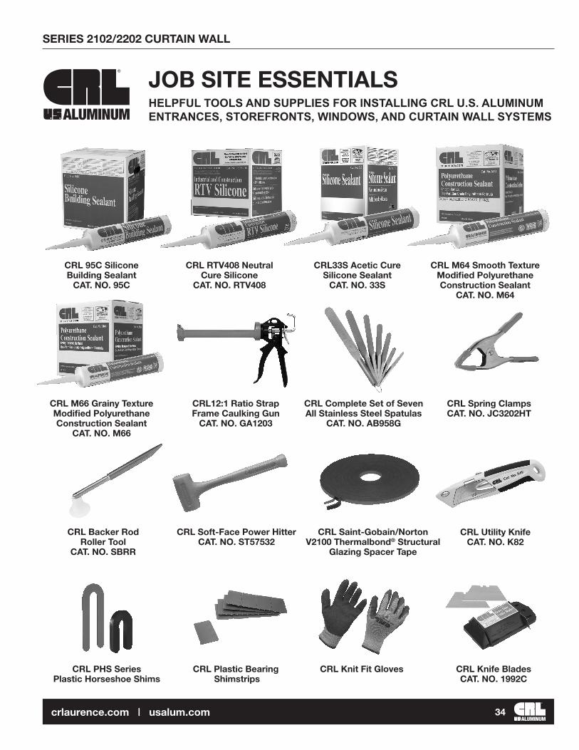
CRL12:1 Ratio Strap Frame Caulking Gun
CAT. NO. GA1203
CRL Complete Set of Seven All Stainless Steel Spatulas
CAT. NO. AB958G
CRL Backer Rod Roller Tool
CAT. NO. SBRR
CRL Plastic Bearing Shimstrips
JOB SITE ESSENTIALSHELPFUL TOOLS AND SUPPLIES FOR INSTALLING CRL U.S. ALUMINUM ENTRANCES, STOREFRONTS, WINDOWS, AND CURTAIN WALL SYSTEMSALUMINUM
CRL Knit Fit Gloves CRL Knife BladesCAT. NO. 1992C
CRL Spring ClampsCAT. NO. JC3202HT
CRL Utility KnifeCAT. NO. K82
CRL Soft-Face Power HitterCAT. NO. ST57532
CRL 95C Silicone Building Sealant
CAT. NO. 95C
CRL RTV408 Neutral Cure Silicone
CAT. NO. RTV408
CRL33S Acetic Cure Silicone Sealant
CAT. NO. 33S
CRL M64 Smooth Texture Modified Polyurethane Construction Sealant
CAT. NO. M64
CRL M66 Grainy Texture Modified Polyurethane Construction Sealant
CAT. NO. M66
CRL PHS Series Plastic Horseshoe Shims
CRL Saint-Gobain/Norton V2100 Thermalbond® Structural
Glazing Spacer Tape

SERIES 2102/2202 CURTAIN WALL
ALUMINUM35crlaurence.com | usalum.com
CRL Gasket RollerCAT. NO. VR10
CRL Gasket CutterCAT. NO. MC80N
CRL Glass CleanerCAT. NO. 1973
CRL Lint Free WipesCAT. NO. 1550
CRL Tape MeasureCAT. NO. 54125
CRL Phenolic L SquareCAT. NO. L48
CRL Glass Marking PencilCAT. NO. GM44
CRL Belt SanderCAT. NO. LD321
CRL Glass Grinding Belts CAT. NO. CRL3X21120X
CRL All Terrain DollyCAT. NO. ATD1
CRL Bond Breaker Tape
CAT. NO. 827T2
CRL Glass Cutters CAT. NO. TC17B
CRL Running Pliers CAT. NO. PPG1
CRL Vacuum Cups CAT. NO. S338
CRL Cordless ScrewdriverCAT. NO. LD823
CRL Hard Hat CAT. NO. ES3452
CRL Portable LadderCAT. NO. 6206
CRL PAL Digital Level Tool CAT. NO. 406065
CRL Glazier’s Rule HolderCAT. NO. RH670
CRL 18V Cordless Driver/Drill
CAT. NO. LD147