Series 15J Inverter Control - Baldor · familiar with the keypad programming and keypad operation...
105
Series 15J Inverter Control Installation and Operating Manual 7/99 MN715J AC INVERTER
Transcript of Series 15J Inverter Control - Baldor · familiar with the keypad programming and keypad operation...
Series 15JInverter Control
Installation and Operating Manual
7/99 MN715J
AC INVERTER

Table of Contents
MN715J Table of Contents i
Section 1Quick Start 1-1. . . . . . . . . . . . . . . . . . . . . . . . . . . . . . . . . . . . . . . . . . .
Overview 1-1. . . . . . . . . . . . . . . . . . . . . . . . . . . . . . . . . . . . . . . . . . . Quick Start Checklist 1-1. . . . . . . . . . . . . . . . . . . . . . . . . . . . . . . . . Power-up Procedure 1-2. . . . . . . . . . . . . . . . . . . . . . . . . . . . . . . . .
Section 2General Information 2-1. . . . . . . . . . . . . . . . . . . . . . . . . . . . . . . . . . .
Year 2000 Compliance 2-1. . . . . . . . . . . . . . . . . . . . . . . . . . . . . . . . CE Compliance 2-1. . . . . . . . . . . . . . . . . . . . . . . . . . . . . . . . . . . . . . Overview 2-1. . . . . . . . . . . . . . . . . . . . . . . . . . . . . . . . . . . . . . . . . . . Limited Warranty 2-2. . . . . . . . . . . . . . . . . . . . . . . . . . . . . . . . . . . . . Safety Notice 2-3. . . . . . . . . . . . . . . . . . . . . . . . . . . . . . . . . . . . . . . .
Section 3Receiving and Installation 3-1. . . . . . . . . . . . . . . . . . . . . . . . . . . . . .
Receiving & Inspection 3-1. . . . . . . . . . . . . . . . . . . . . . . . . . . . . . . Physical Installation 3-1. . . . . . . . . . . . . . . . . . . . . . . . . . . . . . . . . . Control Installation 3-2. . . . . . . . . . . . . . . . . . . . . . . . . . . . . . . . . . .
Optional Remote Keypad Installation 3-2. . . . . . . . . . . . . . . . . Electrical Installation 3-4. . . . . . . . . . . . . . . . . . . . . . . . . . . . . . . . .
System Grounding 3-4. . . . . . . . . . . . . . . . . . . . . . . . . . . . . . . . . Line Impedance 3-6. . . . . . . . . . . . . . . . . . . . . . . . . . . . . . . . . . . Line Reactors 3-6. . . . . . . . . . . . . . . . . . . . . . . . . . . . . . . . . . . . . Load Reactors 3-6. . . . . . . . . . . . . . . . . . . . . . . . . . . . . . . . . . . .
Input Current Requirements 3-6. . . . . . . . . . . . . . . . . . . . . . . . . . . Cover Removal 3-7. . . . . . . . . . . . . . . . . . . . . . . . . . . . . . . . . . . . Terminal Identification 3-7. . . . . . . . . . . . . . . . . . . . . . . . . . . . . .
AC Line Connections 3-8. . . . . . . . . . . . . . . . . . . . . . . . . . . . . . . . . Reduced Input Voltage Derating 3-8. . . . . . . . . . . . . . . . . . . . . Power Disconnect 3-8. . . . . . . . . . . . . . . . . . . . . . . . . . . . . . . . . Protective Devices 3-8. . . . . . . . . . . . . . . . . . . . . . . . . . . . . . . . . Three Phase Wire Size and Protection Devices 3-9. . . . . . . . 3 Phase Installation 3-10. . . . . . . . . . . . . . . . . . . . . . . . . . . . . . . . 115VAC 1 Phase Wire Size and Protection Devices 3-11. . . . 230VAC Single Phase Derating for Three Phase Controls 3-12
Motor Brake Connections 3-13. . . . . . . . . . . . . . . . . . . . . . . . . . . . . Optional Dynamic Brake Hardware 3-13. . . . . . . . . . . . . . . . . . . . .

ii Table of Contents MN715J
Inputs and Outputs 3-14. . . . . . . . . . . . . . . . . . . . . . . . . . . . . . . . . . . Analog Inputs 3-14. . . . . . . . . . . . . . . . . . . . . . . . . . . . . . . . . . . . . Analog Output 3-15. . . . . . . . . . . . . . . . . . . . . . . . . . . . . . . . . . . . . Relay Outputs 3-15. . . . . . . . . . . . . . . . . . . . . . . . . . . . . . . . . . . . . External Trip Input 3-16. . . . . . . . . . . . . . . . . . . . . . . . . . . . . . . . .
Selection of Operating Mode 3-17. . . . . . . . . . . . . . . . . . . . . . . . . . Keypad Connection 3-17. . . . . . . . . . . . . . . . . . . . . . . . . . . . . . . . Standard Run 3 Wire Connection 3-19. . . . . . . . . . . . . . . . . . . . 7 Speed Connection 3-20. . . . . . . . . . . . . . . . . . . . . . . . . . . . . . . Fan Pump 2 Wire Connection 3-21. . . . . . . . . . . . . . . . . . . . . . . Fan Pump 3 Wire Connection 3-22. . . . . . . . . . . . . . . . . . . . . . . Process Control Connection 3-23. . . . . . . . . . . . . . . . . . . . . . . . . 3 Speed Analog 2 Wire Connection 3-24. . . . . . . . . . . . . . . . . . 3 Speed Analog 3 Wire Connection 3-25. . . . . . . . . . . . . . . . . . EPOT 2 Wire Connection 3-26. . . . . . . . . . . . . . . . . . . . . . . . . . . EPOT 3 Wire Connection 3-27. . . . . . . . . . . . . . . . . . . . . . . . . . .
Pre-Operation Checklist 3-28. . . . . . . . . . . . . . . . . . . . . . . . . . . . . . . Power-up Procedure 3-28. . . . . . . . . . . . . . . . . . . . . . . . . . . . . . . . .
Section 4Programming and Operation 4-1. . . . . . . . . . . . . . . . . . . . . . . . . . .
Overview 4-1. . . . . . . . . . . . . . . . . . . . . . . . . . . . . . . . . . . . . . . . . . . Operation Examples 4-4. . . . . . . . . . . . . . . . . . . . . . . . . . . . . . . . . .
Operating the Control from the Keypad 4-4. . . . . . . . . . . . . . . Accessing the Keypad JOG Command 4-4. . . . . . . . . . . . . . . Speed Adjustment using Local Speed Reference 4-5. . . . . . Speed Adjustment using Arrow Keys 4-6. . . . . . . . . . . . . . . . .
Display Mode 4-7. . . . . . . . . . . . . . . . . . . . . . . . . . . . . . . . . . . . . . . . Adjusting Display Contrast 4-7. . . . . . . . . . . . . . . . . . . . . . . . . . Display Screens 4-8. . . . . . . . . . . . . . . . . . . . . . . . . . . . . . . . . . . Fault Log Access 4-9. . . . . . . . . . . . . . . . . . . . . . . . . . . . . . . . . . Diagnostic Information Access 4-10. . . . . . . . . . . . . . . . . . . . . . .
Program Mode 4-12. . . . . . . . . . . . . . . . . . . . . . . . . . . . . . . . . . . . . . . Parameter Blocks Access for Programming 4-13. . . . . . . . . . . . . .
Changing Parameter Values 4-14. . . . . . . . . . . . . . . . . . . . . . . . . Reset Parameters to Factory Settings 4-15. . . . . . . . . . . . . . . . Parameter Definitions 4-16. . . . . . . . . . . . . . . . . . . . . . . . . . . . . .
Parameter Block Definitions 4-17. . . . . . . . . . . . . . . . . . . . . . . . . . .

MN715J Table of Contents iii
Section 5Troubleshooting 5-1. . . . . . . . . . . . . . . . . . . . . . . . . . . . . . . . . . . . . .
No Keypad Display - Display Contrast Adjustment 5-1. . . . . . . . Wrong Language Selection 5-2. . . . . . . . . . . . . . . . . . . . . . . . . . . .
Diagnostic Information Access 5-3. . . . . . . . . . . . . . . . . . . . . . . How to Access the Fault Log 5-5. . . . . . . . . . . . . . . . . . . . . . . . . . How to Clear the Fault Log 5-6. . . . . . . . . . . . . . . . . . . . . . . . . . . . Electrical Noise Considerations 5-12. . . . . . . . . . . . . . . . . . . . . . . .
Relay and Contactor Coils 5-12. . . . . . . . . . . . . . . . . . . . . . . . . . Wires between Controls and Motors 5-12. . . . . . . . . . . . . . . . . . Special Drive Situations 5-13. . . . . . . . . . . . . . . . . . . . . . . . . . . . Special Motor Considerations 5-13. . . . . . . . . . . . . . . . . . . . . . . Analog Signal Wires 5-13. . . . . . . . . . . . . . . . . . . . . . . . . . . . . . .
Section 6Specifications and Product Data 6-1. . . . . . . . . . . . . . . . . . . . . . . .
Specifications: 6-1. . . . . . . . . . . . . . . . . . . . . . . . . . . . . . . . . . . . . . . Operating Conditions: 6-1. . . . . . . . . . . . . . . . . . . . . . . . . . . . . . . . Keypad Display: 6-2. . . . . . . . . . . . . . . . . . . . . . . . . . . . . . . . . . . . . Control Specifications: 6-2. . . . . . . . . . . . . . . . . . . . . . . . . . . . . . . . Analog Inputs: 6-3. . . . . . . . . . . . . . . . . . . . . . . . . . . . . . . . . . . . . . . Analog Output: 6-4. . . . . . . . . . . . . . . . . . . . . . . . . . . . . . . . . . . . . . Digital Inputs: 6-4. . . . . . . . . . . . . . . . . . . . . . . . . . . . . . . . . . . . . . . . Digital Outputs: 6-4. . . . . . . . . . . . . . . . . . . . . . . . . . . . . . . . . . . . . . Fault Indications: 6-4. . . . . . . . . . . . . . . . . . . . . . . . . . . . . . . . . . . . . Ratings 6-5. . . . . . . . . . . . . . . . . . . . . . . . . . . . . . . . . . . . . . . . . . . . . Terminal Tightening Torque Specifications 6-5. . . . . . . . . . . . . . . Mounting Dimensions 6-6. . . . . . . . . . . . . . . . . . . . . . . . . . . . . . . . .
Appendix ADynamic Brake Hardware A-1. . . . . . . . . . . . . . . . . . . . . . . . . . . . . . . Appendix BParameter Values B-1. . . . . . . . . . . . . . . . . . . . . . . . . . . . . . . . . . . . . . Appendix CRemote Keypad Mounting Template C-1. . . . . . . . . . . . . . . . . . . . . .

iv Table of Contents MN715J

Section 1Quick Start
MN715J Quick Start 1-1
OverviewIf you are an experienced user of Baldor controls, you are probably alreadyfamiliar with the keypad programming and keypad operation methods. If so,this quick start guide has been prepared for you. This procedure will helpget your system up and running in the keypad mode quickly and will allowmotor and control operation to be verified. It assumes that the Control andMotor are correctly installed (see Section 3 for procedures) and that youhave an understanding of the keypad programming & operation. It is notnecessary to wire the terminal strip to operate in the Keypad mode (Section3 describes how to wire the terminal strip). The quick start procedure is as follows:1. Read the Safety Notice and Precautions in section 2 of this manual.2. Mount the control. Refer to Section 3, “Physical Installation” procedure.3. Connect AC power. Refer to Section 3, “AC Line Connections”.4. Connect the motor. Refer to Section 3, “AC Line Connections”.
Quick Start Checklist Check of electrical items.1. Verify that the AC line voltage at the source matches the control rating.2. Inspect all power connections for accuracy, workmanship and tightness
as well as compliance to codes.3. Verify that the control and motor are grounded to each other and the
control is connected to earth ground.4. Check all signal wiring for accuracy.5. Be certain all brake coils, contactors and relay coils have noise
suppression. This should be an R-C filter for AC coils and reversepolarity diodes for DC coils. MOV type transient suppression is notadequate.
Check of Motors and Couplings1. Verify freedom of motion of motor shaft.2. Verify that all motor couplings are tight without backlash.3. If holding brakes are used, verify they are properly adjusted to fully
release and set to the desired torque value.

1-2 Quick Start MN715J
WARNING: Make sure that unexpected operation of the motorshaft during start up will not cause injury to personnel ordamage to equipment.
Power-up Procedure1. Turn power on. Be sure no faults are displayed on the keypad display.2. Set the Level 1 Input block, Operating Mode to “Keypad”.3. Set the Level 2 Output Limits block, “MIN Output FREQ” parameter.4. Set the Level 2 Output Limits block, “MAX Output FREQ” parameter.5. If the desired peak current limit setting is not correct, set the Level 2
Output Limits block, “PK Current Limit” parameter as desired.6. Enter the following motor data in the Level 2 Motor Data block
parameters:Motor Rated Amps (FLA)Motor Rated Speed (base speed)Motor Mag Amps (no-load current)
7. If External Dynamic Brake hardware is used, set the Level 2 BrakeAdjust block parameters as desired.
8. Set the Level 1 V/HZ Boost block, “V/HZ Profile” parameter for thecorrect V/Hz ratio for your application.
9. If the load is a high initial starting torque type, the torque boost andaccel time may need to be increased. Set the Level 1 V/HZ Boostblock, “Torque Boost” and the Level 1 Accel/Decel Rate block, “AccelTime #1” as required.
10. Select and program additional parameters to suit your application.
The control is now ready for use in keypad mode. The terminal strip wiringmay be changed and different parameter values used for another operatingmode.
Section 2General Information
MN715J General Information 2-1
Year 2000 ComplianceThe motor control products listed below are manufactured or offered for saleby Baldor Electric and are certified to be year 2000 compliant.DC Motor Controls : Series BC100/200, BC19H, BC20H, TSD, UM, UMH.AC Motor Controls : Series ID5, ID10, ID1100, ID15H, ID15J, ID15P, ID15V,ZD17H, ZD18H, ID21H, ZD22H, SD23H, ZD24M, ZD25M, SD26M, BSC,DBSC, BTS, SBTS, FLEX, FLEX+, MINTDRIVE.Position Controllers : PMC, SmartMove, NextMove.Furthermore, year 2000 compliance means that the product will:
Not use dates or perform any date processing.Date information is irrelevant to proper operation; andThere are no problems or issues to address to ensure continued and proper operation of the product listed due to changes in century dates.
CE ComplianceA custom unit may be required, contact Baldor. Compliance to Directive89/336/EEC is the responsibility of the system integrator. A control, motorand all system components must have proper shielding grounding andfiltering as described in MN1383. Please refer to MN1383 for installationtechniques for CE compliance.OverviewThe Baldor Series 15J control is a PWM inverter motor control. The controloperates by converting AC line power into fixed DC power. The DC power isthen pulse width modulated into synthesized three-phase AC line voltage forthe motor. In this way, the control converts the fixed input frequency tovariable output frequency to cause the motor to have variable speedoperation.The rated horsepower of the control is based on a NEMA design B four polemotor and 60Hz operation at nominal rated input voltage. If any other type ofmotor is used, or input voltage other than 230 or 460 VAC is applied to theinput terminals, the control should be sized to the motor using the ratedoutput current of the control.The Baldor Series 15J control may be used in many different applications.It can be programmed to operate in a number of operating modes, PWMrates and output current levels for custom operation.It is the responsibility of the user to determine the optimum operating modefor the application. These choices are programmed using the keypad asexplained in the programming section of this manual.

2-2 General Information MN715J
Limited Warranty
For a period of two (2) years from the date of original purchase,BALDOR will repair or replace without charge controls and accessorieswhich our examination proves to be defective in material orworkmanship. This warranty is valid if the unit has not been tamperedwith by unauthorized persons, misused, abused, or improperly installedand has been used in accordance with the instructions and/or ratingssupplied. This warranty is in lieu of any other warranty or guaranteeexpressed or implied. BALDOR shall not be held responsible for anyexpense (including installation and removal), inconvenience, orconsequential damage, including injury to any person or propertycaused by items of our manufacture or sale. (Some states do not allowexclusion or limitation of incidental or consequential damages, so theabove exclusion may not apply.) In any event, BALDOR’s total liability,under all circumstances, shall not exceed the full purchase price of thecontrol. Claims for purchase price refunds, repairs, or replacementsmust be referred to BALDOR with all pertinent data as to the defect, thedate purchased, the task performed by the control, and the problemencountered. No liability is assumed for expendable items such asfuses.
Goods may be returned only with written notification including aBALDOR Return Authorization Number and any return shipments mustbe prepaid.
MN715J General Information 2-3
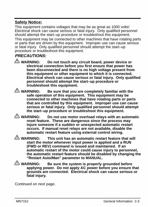
Safety Notice :This equipment contains voltages that may be as great as 1000 volts!Electrical shock can cause serious or fatal injury. Only qualified personnelshould attempt the start–up procedure or troubleshoot this equipment.This equipment may be connected to other machines that have rotating partsor parts that are driven by this equipment. Improper use can cause seriousor fatal injury. Only qualified personnel should attempt the start–upprocedure or troubleshoot this equipment.PRECAUTIONS:
WARNING: Do not touch any circuit board, power device orelectrical connection before you first ensure that power hasbeen disconnected and there is no high voltage present fromthis equipment or other equipment to which it is connected.Electrical shock can cause serious or fatal injury. Only qualifiedpersonnel should attempt the start–up procedure ortroubleshoot this equipment.
WARNING: Be sure that you are completely familiar with thesafe operation of this equipment. This equipment may beconnected to other machines that have rotating parts or partsthat are controlled by this equipment. Improper use can causeserious or fatal injury. Only qualified personnel should attemptthe start–up procedure or troubleshoot this equipment.
WARNING: Do not use motor overload relays with an automaticreset feature. These are dangerous since the process mayinjure someone if a sudden or unexpected automatic restartoccurs. If manual reset relays are not available, disable theautomatic restart feature using external control wiring.
WARNING: This unit has an automatic restart feature that willstart the motor whenever input power is applied and a RUN(FWD or REV) command is issued and maintained. If anautomatic restart of the motor could cause injury to personnel,the automatic restart feature should be disabled by changing the“Restart Auto/Man” parameter to MANUAL.
WARNING: Be sure the system is properly grounded beforeapplying power. Do not apply AC power before you ensure thatgrounds are connected. Electrical shock can cause serious orfatal injury.
Continued on next page.

2-4 General Information MN715J
WARNING: Do not remove cover for at least five (5) minutesafter AC power is disconnected to allow capacitors to discharge.Electrical shock can cause serious or fatal injury.
WARNING: Improper operation of control may cause violentmotion of the motor shaft and driven equipment. Be certain thatunexpected motor shaft movement will not cause injury topersonnel or damage to equipment. Peak torque of severaltimes the rated motor torque can occur during control failure.
WARNING: Motor circuit may have high voltage presentwhenever AC power is applied, even when motor is not rotating.Electrical shock can cause serious or fatal injury.
WARNING: Dynamic brake resistors may generate enough heatto ignite combustible materials. Keep all combustible materialsand flammable vapors away from brake resistors.
Caution: Suitable for use on a circuit capable of delivering notmore than 5,000 RMS symmetrical amperes, at 600VACmaximum.
Caution: Do not supply any power on the External Trip (motorthermostat) leads at J4-17 or J4-18 as the control may bedamaged. Use a dry contact type that requires no externalpower to operate.
Caution: Disconnect motor leads (T1, T2 and T3) from controlbefore you perform a “Megger” test on the motor. Failure todisconnect motor from the control will result in extensivedamage to the control. The control is tested at the factory forhigh voltage / leakage resistance as part of UnderwritersLaboratories Inc. requirements.
Caution: Do not connect AC power to the motor terminals T1, T2and T3. Connecting AC power to these terminals may result indamage to the control.
Caution: Baldor recommends not using “Grounded Leg Delta”transformer power leads that may create ground loops. Instead,we recommend using a four wire Wye.

Section 3Receiving and Installation
MN715J Receiving and Installation 3-1
Receiving & InspectionThe Series 15J Inverter Control is thoroughly tested at the factory andcarefully packaged for shipment. When you receive your control, there areseveral things you should do immediately:1. Observe the condition of the shipping container and report any damage
immediately to the commercial carrier that delivered your control.2. Verify that the control you received is the same as listed on your
purchase order.3. If the control is to be stored for several weeks before use, be sure that it
is stored in a location that conforms to published storage specifications.(Refer to Section 6 of this manual).
Physical InstallationThe mounting location of the 15J is important. It should be installed in anarea that is protected from direct sunlight, corrosives, harmful gases orliquids, dust, metallic particles, and vibration. Exposure to these elementscan reduce the operating life and degrade performance of the control.Several other factors should be carefully evaluated when selecting a locationfor installation:1. For effective cooling and maintenance, the control should be mounted
on a smooth, non-flammable vertical surface. Table 3-1 lists the WattsLoss ratings for enclosure sizing.
2. At least two inches clearance must be provided on all sides for airflow.3. Front access must be provided to allow the control cover to be opened
or removed for service and to allow viewing of the Keypad Display.4. Altitude derating. Up to 3300 feet (1000 meters), no derating required.
Above 3300 feet, derate output current by 2% for each 1000 feet above3300 feet.
5. Temperature derating. Up to 40°C, no derating required. Above 40°C,derate output current by 2% per °C above 40°C. Maximum ambient is 55°C.
Table 3-1 Series 15J Watts Loss Ratings
115VAC 230VAC 460VAC
2.5kHzPWM
7.5kHzPWM
2.5kHzPWM
7.5kHzPWM
2.5kHzPWM
7.5kHzPWM
17 Watts/Amp
20 Watts/Amp
17 Watts/Amp
20 Watts/Amp
19 Watts/Amp
28 Watts/Amp
3-2 Receiving and Installation MN715J
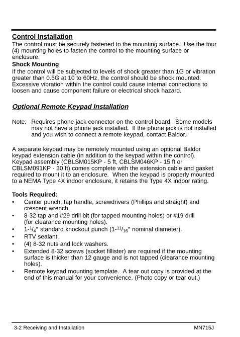
Control InstallationThe control must be securely fastened to the mounting surface. Use the four(4) mounting holes to fasten the control to the mounting surface orenclosure.Shock MountingIf the control will be subjected to levels of shock greater than 1G or vibrationgreater than 0.5G at 10 to 60Hz, the control should be shock mounted.Excessive vibration within the control could cause internal connections toloosen and cause component failure or electrical shock hazard.
Optional Remote Keypad Installation
Note: Requires phone jack connector on the control board. Some modelsmay not have a phone jack installed. If the phone jack is not installedand you wish to connect a remote keypad, contact Baldor.
A separate keypad may be remotely mounted using an optional Baldorkeypad extension cable (in addition to the keypad within the control).Keypad assembly (CBLSM015KP - 5 ft, CBLSM046KP - 15 ft orCBLSM091KP - 30 ft) comes complete with the extension cable and gasketrequired to mount it to an enclosure. When the keypad is properly mountedto a NEMA Type 4X indoor enclosure, it retains the Type 4X indoor rating.
Tools Required:• Center punch, tap handle, screwdrivers (Phillips and straight) and
crescent wrench.• 8-32 tap and #29 drill bit (for tapped mounting holes) or #19 drill
(for clearance mounting holes).• 1-1/4″ standard knockout punch (1-11/16″ nominal diameter).• RTV sealant.• (4) 8-32 nuts and lock washers.• Extended 8-32 screws (socket fillister) are required if the mounting
surface is thicker than 12 gauge and is not tapped (clearance mountingholes).
• Remote keypad mounting template. A tear out copy is provided at theend of this manual for your convenience. (Photo copy or tear out.)
MN715J Receiving and Installation 3-3
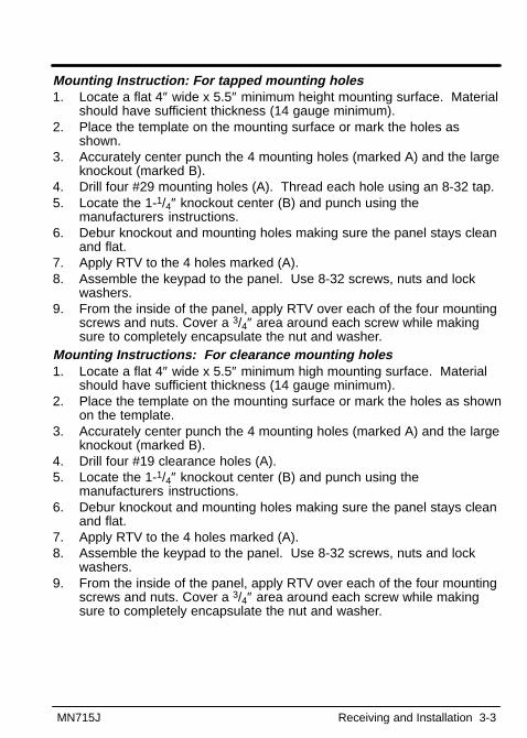
Mounting Instruction: For tapped mounting holes1. Locate a flat 4″ wide x 5.5″ minimum height mounting surface. Material
should have sufficient thickness (14 gauge minimum).2. Place the template on the mounting surface or mark the holes as
shown.3. Accurately center punch the 4 mounting holes (marked A) and the large
knockout (marked B).4. Drill four #29 mounting holes (A). Thread each hole using an 8-32 tap.5. Locate the 1-1/4″ knockout center (B) and punch using the
manufacturers instructions.6. Debur knockout and mounting holes making sure the panel stays clean
and flat.7. Apply RTV to the 4 holes marked (A).8. Assemble the keypad to the panel. Use 8-32 screws, nuts and lock
washers.9. From the inside of the panel, apply RTV over each of the four mounting
screws and nuts. Cover a 3/4″ area around each screw while makingsure to completely encapsulate the nut and washer.
Mounting Instructions: For clearance mounting holes1. Locate a flat 4″ wide x 5.5″ minimum high mounting surface. Material
should have sufficient thickness (14 gauge minimum).2. Place the template on the mounting surface or mark the holes as shown
on the template.3. Accurately center punch the 4 mounting holes (marked A) and the large
knockout (marked B).4. Drill four #19 clearance holes (A).5. Locate the 1-1/4″ knockout center (B) and punch using the
manufacturers instructions.6. Debur knockout and mounting holes making sure the panel stays clean
and flat.7. Apply RTV to the 4 holes marked (A).8. Assemble the keypad to the panel. Use 8-32 screws, nuts and lock
washers.9. From the inside of the panel, apply RTV over each of the four mounting
screws and nuts. Cover a 3/4″ area around each screw while makingsure to completely encapsulate the nut and washer.

3-4 Receiving and Installation MN715J
Electrical InstallationInterconnection wiring is required between the motor control, AC powersource, motor, host control and any operator interface stations. Use listedclosed loop connectors that are of appropriate size for the wire gauge beingused. Connectors are to be installed using crimp tool specified by themanufacturer of the connector. Only Class 1 wiring should be used.System GroundingBaldor Controls are designed to be powered from standard three phase linesthat are electrically symmetrical with respect to ground. System grounding isan important step in the overall installation to prevent problems. The recommended grounding method is shown in Figure 3-1.Ungrounded Distribution SystemWith an ungrounded power distribution system it is possible to have acontinuous current path to ground through the MOV devices. To avoidequipment damage, an isolation transformer with a grounded secondary isrecommended. This provides three phase AC power that is symmetrical withrespect to ground.Input Power ConditioningBaldor controls are designed for direct connection to standard three phaselines that are electrically symmetrical with respect to ground. Certain powerline conditions must be avoided. An AC line reactor or an isolationtransformer may be required for some power conditions.
� If the feeder or branch circuit that provides power to the control haspermanently connected power factor correction capacitors, an input ACline reactor or an isolation transformer should be connected betweenthe power factor correction capacitors and the control.
� If the feeder or branch circuit that provides power to the control haspower factor correction capacitors that are switched on line and off line,the capacitors must not be switched while the control is connected tothe AC power line. If the capacitors are switched on line while thecontrol is still connected to the AC power line, additional protection isrequired. TVSS (Transient Voltage Surge Suppressor) of the properrating should be installed between the AC line reactor or an isolationtransformer and the AC input to the control.

MN715J Receiving and Installation 3-5
Figure 3-1 Recommended System Grounding
L1
AC Main Supply Saf
ety
Gro
und
Driv
en e
arth
gro
und
rod
(pla
nt g
roun
d)
Fou
r W
ire“W
ye”
L1 L2 L3 Ear
th
L2L3
T1
T3
Line
Rea
ctor
Load
Rea
ctor
Rou
te a
ll 4
wire
s L1
, L2,
L3
and
Ear
th(g
roun
d) to
geth
er in
con
duit
or c
able
. Rou
te a
ll 4
wire
s T
1, T
2, T
3 an
d m
otor
grou
nd to
geth
er in
con
duit
or s
hiel
ded
cabl
e.
Con
nect
all
wire
s (in
clud
ing
mot
or g
roun
d) in
side
the
mot
or t
erm
inal
box
.
Gro
und
per
NE
C a
nd L
ocal
cod
es.
Not
e:A
line
rea
ctor
is r
ecom
men
ded
and
mus
t be
orde
red
sepa
rate
ly.
Not
e:A
load
rea
ctor
is
reco
mm
ende
d an
d m
ust
be o
rder
ed s
epar
atel
y.
Bal
dor
Con
trol
T2
Not
e:U
se s
hiel
ded
cabl
e fo
r co
ntro
lsi
gnal
wire
s. R
oute
con
trol
sign
al w
ires
in c
ondu
it.
The
sew
ires
mus
t ke
pt s
epar
ate
from
pow
er a
nd m
otor
wire
s.

3-6 Receiving and Installation MN715J
Line ImpedanceThe Baldor Series 15J control requires a minimum line impedance of 1%.The input impedance of the power lines can be determined as follows:
Measure the line to line voltage at no load and at full rated load. Usethese measured values to calculate impedance as follows:
%Impedance �(VoltsNoLoad � VoltsFullLoad)
(VoltsNoLoad)� 100
Line Reactors3 phase line reactors are available from Baldor. The size of the line reactorto use is based on the maximum continuous load. If providing your own linereactor, use the following formula to calculate the minimum inductancerequired. Table 3-2 lists the input current required for this calculation.
L �
(VL�L � 0.01)
(I � 3� � 377) Where: L Minimum inductance in henrys.
VL-L Input volts measured line to line.0.01 Desired percentage of input impedance (1% shown).I Input current rating of control.377 Constant used with 60Hz power.
Use 314 with 50Hz power.Load ReactorsLine reactors may be used at the control output to the motor. When usedthis way, they are called Load Reactors. Load Reactors serve severalfunctions.� Protect the control from a short circuit at the motor.� Limit the rate of rise of motor surge currents.� Slow the rate of change of power the control delivers to the motor.Load reactors should be installed as close to the control as possible.Input Current Requirements
Table 3-2 Input Current Requirements for Stock Products
115VAC - 1� 230VAC - 3� 460VAC - 3�
Catalog Numbers
InputAmps
Catalog Numbers
InputAmps
Catalog Numbers
InputAmps
ID15J1F33-ER 7.5 ID15J201-ER 4.8 ID15J401-ER 2.4
ID15J1F50-ER 10.2 ID15J201F5-ER 6.9 ID15J401F5-ER 3.5
ID15J1F75-ER 14.4 ID15J202-ER 7.8 ID15J402-ER 3.9
ID15J101-ER 16.6 ID15J203-ER 11.0 ID15J403-ER 5.5
ID15J405-ER 8.7
MN715J Receiving and Installation 3-7
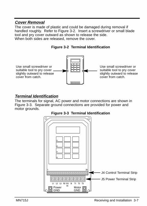
Cover RemovalThe cover is made of plastic and could be damaged during removal ifhandled roughly. Refer to Figure 3-2. Insert a screwdriver or small bladetool and pry cover outward as shown to release the side. When both sides are released, remove the cover.
Figure 3-2 Terminal Identification
Use small screwdriver orsuitable tool to pry coverslightly outward to releasecover from catch.
Use small screwdriver orsuitable tool to pry coverslightly outward to releasecover from catch.
Terminal IdentificationThe terminals for signal, AC power and motor connections are shown inFigure 3-3. Separate ground connections are provided for power and motor grounds.
Figure 3-3 Terminal Identification
J4 Control Terminal Strip
J5 Power Terminal Strip
Power GND
Motor GND
L1 L2 L3 T1 T2 T3B�R2 R1/
B+
1 20

3-8 Receiving and Installation MN715J
AC Line ConnectionsBe sure all power to the control is disconnected before proceeding. If powerhas been applied to the control, wait at least 5 minutes after powerdisconnect for residual voltage across the bus capacitors to discharge.Reduced Input Voltage DeratingAll power ratings stated in Section 6 are for the nominal AC input voltages(115, 230, or 460). The power rating of the control must be reduced whenoperating at a reduced input voltage. The amount of reduction is the ratio ofthe voltage change.Examples:A 5hp, 230VAC control operating at 208VAC has a reduced power rating of4.52hp.
5HP � 208VAC230VAC
� 4.52hp
Likewise, a 5hp, 460VAC control operating at 380VAC has a reduced powerrating of 4.13hp.
5HP � 380VAC460VAC
� 4.13hp
Power DisconnectA power disconnect should be installed between the input power service andthe control for a fail-safe method to disconnect power. The control will remainin a powered-up condition until all input power is removed from the controland the internal bus voltage is discharged.Protective DevicesRecommended fuse sizes are based on the following:115% of maximum continuous current for time delay.150% of maximum continuous current for Fast or Very Fast action.Note: These general size recommendations do not consider harmonic
currents or ambient temperatures greater than 40°C.Be sure a suitable input power protection device is installed. Use therecommended circuit breaker or fuses listed in Tables 3-3 and 3-4. Input andoutput wire size is based on the use of copper conductor wire rated at 75°C.The table is specified for NEMA B motors.
Circuit Breaker: 1 phase , thermal magnetic. Equal to GE type THQ or TEB for 230VAC
3 phase , thermal magnetic. Equal to GE type THQ or TEB for 230VAC or Equal to GE type TED for 460VAC
Continued on next page.
MN715J Receiving and Installation 3-9
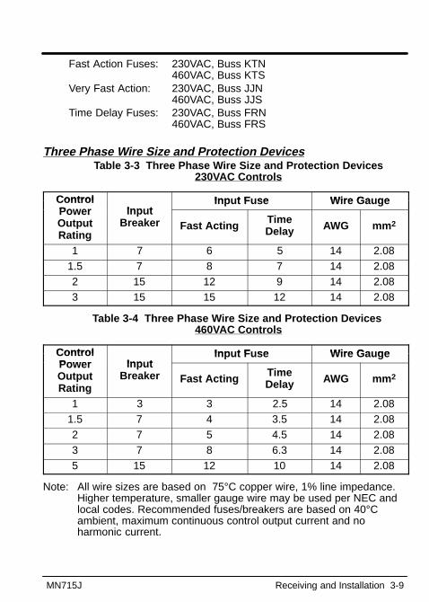
Fast Action Fuses: 230VAC, Buss KTN 460VAC, Buss KTS
Very Fast Action: 230VAC, Buss JJN 460VAC, Buss JJS
Time Delay Fuses: 230VAC, Buss FRN 460VAC, Buss FRS
Three Phase Wire Size and Protection DevicesTable 3-3 Three Phase Wire Size and Protection Devices
230VAC Controls
Control Inp t F se Wire Ga geContro lPower Inp t
Input Fuse Wire GaugePowerOutputRating
InputBreaker Fast Acting Time
Delay AWG mm 2
1 7 6 5 14 2.081.5 7 8 7 14 2.082 15 12 9 14 2.083 15 15 12 14 2.08
Table 3-4 Three Phase Wire Size and Protection Devices 460VAC Controls
Control Inp t F se Wire Ga geContro lPower Inp t
Input Fuse Wire GaugePowerOutputRating
InputBreaker Fast Acting Time
Delay AWG mm 2
1 3 3 2.5 14 2.081.5 7 4 3.5 14 2.082 7 5 4.5 14 2.083 7 8 6.3 14 2.085 15 12 10 14 2.08
Note: All wire sizes are based on 75°C copper wire, 1% line impedance.Higher temperature, smaller gauge wire may be used per NEC andlocal codes. Recommended fuses/breakers are based on 40°Cambient, maximum continuous control output current and noharmonic current.
3-10 Receiving and Installation MN715J
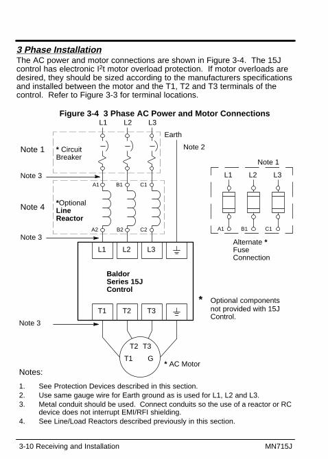
3 Phase InstallationThe AC power and motor connections are shown in Figure 3-4. The 15Jcontrol has electronic I2t motor overload protection. If motor overloads aredesired, they should be sized according to the manufacturers specificationsand installed between the motor and the T1, T2 and T3 terminals of thecontrol. Refer to Figure 3-3 for terminal locations.
Figure 3-4 3 Phase AC Power and Motor Connections L1 L2 L3
L1 L2 L3
* CircuitBreaker
Earth
* AC Motor
Note 2
Note 3
BaldorSeries 15JControl
*OptionalLine Reactor
Note 1
Note 3
Note 3
A1 B1 C1
A2 B2 C2
T1 T2 T3
Note 4
T1
T2 T3
G
L1 L2 L3
Alternate *FuseConnection
Note 1
A1 B1 C1
Notes:
1. See Protection Devices described in this section.2. Use same gauge wire for Earth ground as is used for L1, L2 and L3.3. Metal conduit should be used. Connect conduits so the use of a reactor or RC
device does not interrupt EMI/RFI shielding.4. See Line/Load Reactors described previously in this section.
* Optional componentsnot provided with 15JControl.

MN715J Receiving and Installation 3-11
115VAC 1 Phase Wire Size and Protection DevicesTable 3-5 Wire Size and Protection Devices - 1 phase
Control Inp t F se Wire Ga geContro lO tp t Input Input Fuse Wire GaugeOutputRating
HP
InputBreakerAmps
Fast ActingAmps
Time DelayAmps AWG mm 2
0.33 10 12 10 14 2.080.5 12.5 15 15 14 2.08
0.75 17.5 20 17.5 12 3.311.0 20 25 20 12 3.31
Note: All wire sizes are based on 75°C copper wire, 1% line impedance.Higher temperature, smaller gauge wire may be used per NEC andlocal codes. Recommended fuses/breakers are based on 40°Cambient, maximum continuous control output current and noharmonic current.
Figure 3-5 Single Phase AC Power and Motor Connections
L1 N
L1 N
Earth
* AC Motor is not provided with control.
Baldor Series 15J Control
Metal conduit should be used to shield outputwires (from T1, T2, T3 of control to T1, T2, T3of motor).
T1 T2 T3
T1
T2 T3
G
Shield wires inside a metal conduit.
Motor wire should be sized using the 3 phaseinformation in Table 3-3.
L1
Alternate *Fuse Connection
* CircuitBreakershown
* Optional components notprovided with 15J Control.
3-12 Receiving and Installation MN715J
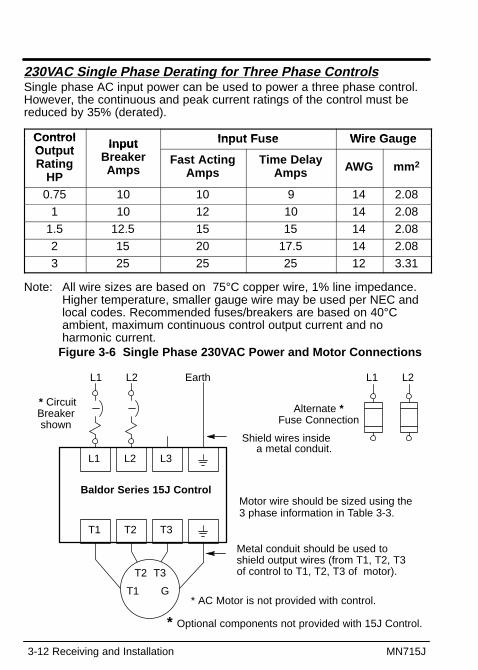
230VAC Single Phase Derating for Three Phase ControlsSingle phase AC input power can be used to power a three phase control.However, the continuous and peak current ratings of the control must bereduced by 35% (derated).
Control Inp t F se Wire Ga geContro lO tp t Input Input Fuse Wire GaugeOutputRating
HP
InputBreakerAmps
Fast ActingAmps
Time DelayAmps AWG mm 2
0.75 10 10 9 14 2.081 10 12 10 14 2.08
1.5 12.5 15 15 14 2.082 15 20 17.5 14 2.083 25 25 25 12 3.31
Note: All wire sizes are based on 75°C copper wire, 1% line impedance.Higher temperature, smaller gauge wire may be used per NEC andlocal codes. Recommended fuses/breakers are based on 40°Cambient, maximum continuous control output current and noharmonic current.
Figure 3-6 Single Phase 230VAC Power and Motor Connections
L1 L2
L1 L2 L3
Earth
* AC Motor is not provided with control.
Baldor Series 15J Control
Metal conduit should be used toshield output wires (from T1, T2, T3of control to T1, T2, T3 of motor).
T1 T2 T3
T1
T2 T3
G
Shield wires inside a metal conduit.
Motor wire should be sized using the3 phase information in Table 3-3.
L1 L2
Alternate *Fuse Connection
* CircuitBreakershown
* Optional components not provided with 15J Control.
MN715J Receiving and Installation 3-13
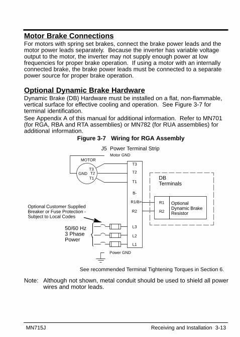
Motor Brake ConnectionsFor motors with spring set brakes, connect the brake power leads and themotor power leads separately. Because the inverter has variable voltageoutput to the motor, the inverter may not supply enough power at lowfrequencies for proper brake operation. If using a motor with an internallyconnected brake, the brake power leads must be connected to a separatepower source for proper brake operation.
Optional Dynamic Brake HardwareDynamic Brake (DB) Hardware must be installed on a flat, non-flammable,vertical surface for effective cooling and operation. See Figure 3-7 forterminal identification.See Appendix A of this manual for additional information. Refer to MN701(for RGA, RBA and RTA assemblies) or MN782 (for RUA assemblies) foradditional information.
Figure 3-7 Wiring for RGA Assembly
See recommended Terminal Tightening Torques in Section 6.
Optional Customer SuppliedBreaker or Fuse Protection -Subject to Local Codes
MOTOR
50/60 Hz3 PhasePower
Motor GND
B-
R1/B+
T3
T2
T1
L3
L2
L1
Power GND
GNDT1T2
T3
OptionalDynamic BrakeResistor
J5 Power Terminal Strip
DBTerminals
R1
R2R2
Note: Although not shown, metal conduit should be used to shield all powerwires and motor leads.
3-14 Receiving and Installation MN715J
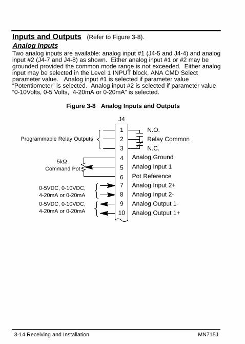
Inputs and Outputs (Refer to Figure 3-8).Analog InputsTwo analog inputs are available: analog input #1 (J4-5 and J4-4) and analoginput #2 (J4-7 and J4-8) as shown. Either analog input #1 or #2 may begrounded provided the common mode range is not exceeded. Either analoginput may be selected in the Level 1 INPUT block, ANA CMD Selectparameter value. Analog input #1 is selected if parameter value“Potentiometer” is selected. Analog input #2 is selected if parameter value“0-10Volts, 0-5 Volts, 4-20mA or 0-20mA” is selected.
Figure 3-8 Analog Inputs and Outputs
8
9
10
Analog Input 2-
Analog Output 1-
J4
N.O.
Relay Common
N.C.Analog Ground
Analog Input 1
Pot Reference
Analog Input 2+
Analog Output 1+
1
2
3
4
5
67
5k� Command Pot
Programmable Relay Outputs
0-5VDC, 0-10VDC, 4-20mA or 0-20mA
0-5VDC, 0-10VDC, 4-20mA or 0-20mA

MN715J Receiving and Installation 3-15
Analog Input #1The single ended analog input #1 can be used when the controller is set toStandard Run, 7 Speed, Fan Pump 2 Wire, Fan Pump 3 Wire, ProcessControl, 3 SPD ANA 2Wire, 3 SPD ANA 3Wire, EPOT 2Wire or EPOT 3Wire(not Keypad).The single ended analog input #1 can be used as a Speed command (Level1 Input block, ANA CMD Select=Potentiometer).Note: A potentiometer value of 5k� to 10k�, 0.5 watt may be used.1. Connect the wires from the 5K� pot at the J4 terminal strip. One end of
the pot is connected to J4-4 (analog ground) and the other end isconnected to J4-6 (reference voltage).
2. Connect the wiper of the pot to J4-5. The voltage across terminals J4-4and J4-5 is the speed command input.
Analog Input #2Analog input #2 accepts a differential command 0-5VDC, 0-10VDC, 4-20 mAor 0-20 mA. The (Differential) command mode is defined in the Level 1 Inputblock ANA CMD Select parameter.Note: Analog Input #2 can be used with Standard Run, 7 Speed, Fan Pump
2 Wire, Fan Pump 3 Wire, Process Control, 3 SPD ANA 2Wire or 3SPD ANA 3Wire, EPOT 2Wire or EPOT 3Wire (not Keypad).
1. Connect the Analog Input + wire to J4-7 and the - wire to J4-8.2. If using a 0-20 mA or 4-20 mA command signal, “Level 1 Input block,
ANA CMD Select” parameter should be set to 0-20 mA or 4-20 mA.
Analog OutputOne programmable analog output is provided at J4-10 and J4-9. The outputis scaled 0 - 5 VDC, 0 - 10 VDC, 4-20mA or 0-20mA. The output function isprogrammed in the Level 1 Output block, Analog Out parameter value. Thescaling of the output is programmed in the Level 1 Output block, AnalogScale.
Relay OutputsOne normally open (N.O.) and one normally closed (N.C.) relay contact isavailable at terminals J4-1, J4-2 and J4-3. J4-2 is relay common. Theoutput is programmable in the Level 1 Output block, Relay Outputparameter.1. Connect the N.O. contact to another circuit by attaching the wires to
J4-1 and J4-2.2. Connect the N.C. contact to another circuit by attaching the wires to
J4-3 and J4-2.
3-16 Receiving and Installation MN715J
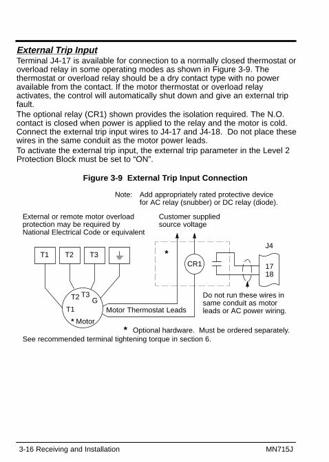
External Trip InputTerminal J4-17 is available for connection to a normally closed thermostat oroverload relay in some operating modes as shown in Figure 3-9. Thethermostat or overload relay should be a dry contact type with no poweravailable from the contact. If the motor thermostat or overload relayactivates, the control will automatically shut down and give an external tripfault.The optional relay (CR1) shown provides the isolation required. The N.O.contact is closed when power is applied to the relay and the motor is cold.Connect the external trip input wires to J4-17 and J4-18. Do not place thesewires in the same conduit as the motor power leads.To activate the external trip input, the external trip parameter in the Level 2Protection Block must be set to “ON”.
Figure 3-9 External Trip Input Connection
T1 T2 T3
T1
T2 T3G
* Motor
1718
J4
Do not run these wires insame conduit as motorleads or AC power wiring.
Customer supplied source voltage
Motor Thermostat Leads
CR1*
* Optional hardware. Must be ordered separately.See recommended terminal tightening torque in section 6.
Note: Add appropriately rated protective device for AC relay (snubber) or DC relay (diode).
External or remote motor overloadprotection may be required byNational Electrical Code or equivalent

MN715J Receiving and Installation 3-17
Selection of Operating Mode (and Connection Diagram)Several operating modes are available that define the basic motor controlsetup and the operation of the input and output terminals. These operatingmodes are selected by programming the Operating Mode parameter in theLevel 1 Input programming Block. Available operating modes include:
• Keypad• Standard Run, 3 Wire• 7 Speed• Fan Pump 2 Wire• Fan Pump 3 Wire• Process Control• 3 Speed Analog 2 Wire• 3 Speed Analog 3 Wire• Electronic Potentiometer 2 Wire• Electronic Potentiometer 3 Wire
Each mode requires connections to the J4 terminal strip (except that all J4connections are optional in the keypad mode).
Note: J4-19 and J4-20 are not to be used. These terminals are reservedfor manufacturing use only.
Keypad ConnectionThe Keypad operating mode allows the control to be operated from thekeypad. In this mode, no control connection wiring is required. However,the Stop, Accel/Decel select and External Trip inputs may optionally be used.All other digital inputs are inactive. The analog output and relay outputsremain active at all times.
For operation in Keypad mode, set the Level 1 Input block, Operating Modeparameter to Keypad.

3-18 Receiving and Installation MN715J
To use the Stop input, J4-13 must be connected and the Level 1 KeypadSetup block, LOC. Hot Start parameter must be set to ON. The Stop line isnormally closed. When opened, the motor will COAST or REGEN to a stopdepending upon the setting of Level 1 Keypad Setup block Keypad Stop Keyparameter value. Closing the input will immediately start the motor if a runcommand was given before the stop line was opened.The Accel/Decel select input is used to select ACC / DEC / S-CURVE group 1or group 2. This connection is made at J4-14.The External Trip input is used to cause a fault condition during a motorover-temperature condition. The External Trip input (J4-17) must beconnected and the External Trip parameter in the Level 2 Protection blockmust be set to ON. When J4-17 is opened, the motor will coast to a stopand an External Trip fault will be displayed on the keypad display.
Figure 3-10 Keypad Connection Diagram
11
12
13
14
15
16
17
18
Accel/Decel Select
External Trip
J4
Input CommonRefer to Figure 3-9.
See recommended terminal tightening torques in Section 6.
Stop
Keypad Only ConnectionJ4-13 If J4-13 is connected, you must set Level 1 Keypad Setup block,
LOC. Hot Start parameter to “ON” to activate the opto input.CLOSED allows normal control operation.OPEN disables the control and the motor will coast or brake to astop. The motor will restart when J4-13 closes after open.
J4-14 OPEN selects ACC / DEC / S-CURVE group 1. CLOSED selects group 2.
J4-17 If J4-17 is connected, you must set Level 2 Protection block,External Trip to “ON” to activate the opto input.OPEN causes an external trip fault. The control will disable andthe motor coasts to a stop. An external trip fault is displayed (alsologged in the fault log). CLOSED allows normal operation.

MN715J Receiving and Installation 3-19
Standard Run 3 Wire ConnectionFigure 3-11 Standard Run 3-Wire Connection Diagram
11
12
13
14
15
16
17
18
Forward
Reverse
Stop
Accel/Decel Select
Speed Select 1
Speed Select 2
External Trip
Input CommonRefer to Figure 3-9.
J4
Refer to Table 3-6
See recommended terminal tightening torques in Section 6.
Table 3-6 Speed Select
Function Speed Select 1 Speed Select 2ANA CMD Select Open OpenPreset Speed 1 Closed OpenPreset Speed 2 Closed ClosedPreset Speed 3 Open Closed
J4-11 Momentary CLOSED starts Forward motor rotation.J4-12 Momentary CLOSED starts Reverse motor rotation.J4-13 Momentary OPEN motor decels to stop (depending on Keypad
Stop mode).J4-14 OPEN selects ACC / DEC / S-CURVE group 1.
CLOSED selects group 2.J4-15 Selects preset speeds as defined in Table 3-6.J4-16 Selects preset speeds as defined in Table 3-6.J4-17 If J4-17 is connected, you must set Level 2 Protection block,
External Trip to “ON” to activate the opto input.OPEN causes an external trip fault. The control will disable andthe motor coasts to a stop. An external trip fault is displayed (alsologged in the fault log). CLOSED allows normal operation.
3-20 Receiving and Installation MN715J
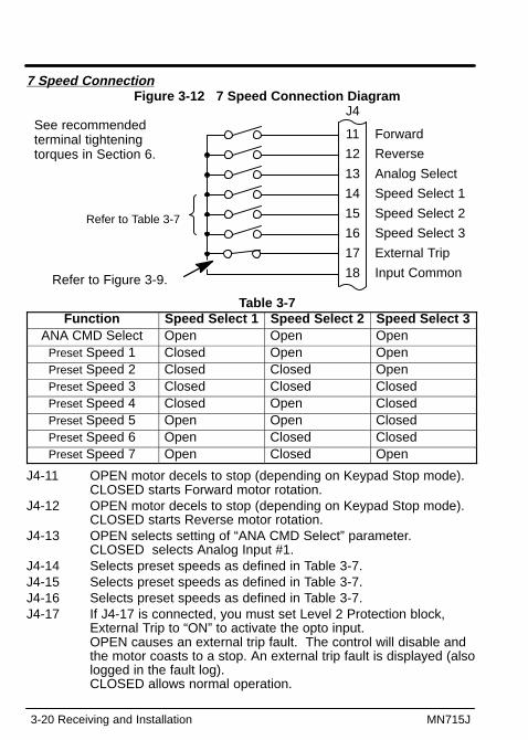
7 Speed ConnectionFigure 3-12 7 Speed Connection Diagram
11
12
13
14
15
16
17
18
Forward
Reverse
Analog Select
Speed Select 1
Speed Select 2
Speed Select 3
External Trip
J4
Input CommonRefer to Figure 3-9.
See recommended terminal tightening torques in Section 6.
Refer to Table 3-7
Table 3-7Function Speed Select 1 Speed Select 2 Speed Select 3
ANA CMD Select Open Open OpenPreset Speed 1 Closed Open OpenPreset Speed 2 Closed Closed OpenPreset Speed 3 Closed Closed ClosedPreset Speed 4 Closed Open ClosedPreset Speed 5 Open Open ClosedPreset Speed 6 Open Closed ClosedPreset Speed 7 Open Closed Open
J4-11 OPEN motor decels to stop (depending on Keypad Stop mode).CLOSED starts Forward motor rotation.
J4-12 OPEN motor decels to stop (depending on Keypad Stop mode).CLOSED starts Reverse motor rotation.
J4-13 OPEN selects setting of “ANA CMD Select” parameter. CLOSED selects Analog Input #1.
J4-14 Selects preset speeds as defined in Table 3-7.J4-15 Selects preset speeds as defined in Table 3-7.J4-16 Selects preset speeds as defined in Table 3-7.J4-17 If J4-17 is connected, you must set Level 2 Protection block,
External Trip to “ON” to activate the opto input.OPEN causes an external trip fault. The control will disable andthe motor coasts to a stop. An external trip fault is displayed (alsologged in the fault log). CLOSED allows normal operation.

MN715J Receiving and Installation 3-21
Fan Pump 2 Wire ConnectionFigure 3-13 Fan/Pump 2 Wire Connection Diagram
11
12
13
14
15
16
17
18
Forward
Reverse
Analog Select
Firestat
Freezestat
Run Command
Speed Command
Input CommonRefer to Figure 3-9.
J4
Refer to Table 3-8
See recommended terminal tightening torques in Section 6.
Table 3-8
Function Firestat Freezestat CommentANA CMD Select Closed Closed Firestat and Freezestat
l i t th tPreset Speed 1 Open Closed are alarm inputs thatoverride all speed
Preset Speed 1 Open Open override all speedcommands including
Preset Speed 2 Closed Opencommands includingthe keypad.
J4-11 OPEN motor decels to stop (depending on Keypad Stop mode).CLOSED starts Forward motor rotation.
J4-12 OPEN motor decels to stop (depending on Keypad Stop mode).CLOSED starts Reverse motor rotation.
J4-13 OPEN selects setting of “ANA CMD Select” parameter. CLOSED selects Analog Input #1.
J4-14 OPEN selects preset speed #1 regardless of the SpeedCommand input J4-13.
J4-15 OPEN selects preset speed #2 regardless of the SpeedCommand input J4-13.
J4-16 OPEN selects direction commands from Keypad. CLOSED selects direction commands from terminal strip.
J4-17 OPEN selects speed commanded from Keypad. CLOSED selects terminal strip speed source (selected in theLevel 1 Input block, ANA CMD Select parameter).

3-22 Receiving and Installation MN715J
Fan Pump 3 Wire ConnectionFigure 3-14 Fan/Pump 3 Wire Connection Diagram
11
12
13
14
15
16
17
18
Forward
Reverse
Stop
Firestat
Freezestat
Run Command
Speed Command
Input Common
J4
Refer to Table 3-9
See recommended terminal tightening torques in Section 6.
Table 3-9
Function Firestat Freezestat CommentANA CMD Select Closed Closed Firestat and Freezestat
are alarm inputs thatPreset Speed 1 Open Closed are alarm inputs thatoverride all speed
Preset Speed 1 Open Openoverride all speedcommands including
Preset Speed 2 Closed Opencommands includingthe keypad.
J4-11 Momentary CLOSED starts Forward motor rotation.J4-12 Momentary CLOSED starts Reverse motor rotation.J4-13 Momentary OPEN motor decels to stop (depending on Keypad
Stop mode).J4-14 OPEN selects preset speed #1 regardless of the Speed
Command input J4-13.CLOSED allows normal operation.
J4-15 OPEN selects preset speed #2 regardless of the SpeedCommand input J4-13. CLOSED allows normal operation.
J4-16 OPEN selects direction commands from Keypad. CLOSED selects direction commands from terminal strip.
J4-17 OPEN selects speed commanded from Keypad. CLOSED selects terminal strip speed source (selected in theLevel 1 Input block, ANA CMD Select parameter).

MN715J Receiving and Installation 3-23
Process Control Connection
Figure 3-15 Process Control Connection Diagram
11
12
13
14
15
16
17
18
Forward
Reverse
Process/CMD Select
Jog Forward
Jog Reverse
Fault Reset
External Trip
Input CommonRefer to Figure 3-9.
J4See recommended terminal tightening torques in Section 6.
J4-11 OPEN motor decels to stop (depending on Keypad Stop mode).CLOSED starts Forward motor rotation.
J4-12 OPEN motor decels to stop (depending on Keypad Stop mode).CLOSED starts Reverse motor rotation.
Note: Simultaneous closure of J4-11 and J4-12 will cause the motor toregen to stop (not coast).
J4-13 OPEN selects the input specified in the Level 1 Input block, ANA CMD Select parameter.CLOSED selects selects the closed loop feature of the ProcessControl mode.
Note: The process will run in one direction. For example, if the forward line(J4-11) is closed, the process will only run in the forward direction.The PID algorithm will not reverse the direction automatically.
J4-14 OPEN allows normal operation.CLOSED jogs the motor in the forward direction.
J4-15 OPEN allows normal operation.CLOSED jogs the motor in the reverse direction.
Note: Simultaneous closure of J4-14 and J4-15 selects jog forward.J4-16 OPEN allows normal operation.
CLOSED to reset a fault condition.J4-17 If J4-17 is connected, you must set Level 2 Protection block,
External Trip to “ON” to activate the opto input.OPEN causes an external trip fault. The control will disable andthe motor coasts to a stop. An external trip fault is displayed (alsologged in the fault log). CLOSED allows normal operation.

3-24 Receiving and Installation MN715J
3 Speed Analog 2 Wire ConnectionFigure 3-16 3 Speed Analog 2 Wire Connection Diagram
11
12
13
14
15
16
17
18
Forward
Reverse
Analog Select
Speed Select 1
Speed Select 2
Run Command
Speed Command
Input Common
J4
Refer to Table 3-10
See recommended terminal tightening torques in Section 6.
Table 3-10
Function Speed Select 1 Speed Select 2ANA CMD Select Open Open
Preset Speed 1 Closed OpenPreset Speed 2 Closed ClosedPreset Speed 3 Open Closed
J4-11 OPEN motor decels to stop (depending on Keypad Stop mode).CLOSED starts Forward motor rotation.
J4-12 OPEN motor decels to stop (depending on Keypad Stop mode).CLOSED starts Reverse motor rotation.
J4-13 OPEN selects setting of “ANA CMD Select” parameter. CLOSED selects Analog Input #1.
J4-14 Selects preset speeds as defined in Table 3-10.J4-15 Selects preset speeds as defined in Table 3-10.J4-16 OPEN selects direction commands from Keypad.
CLOSED selects direction commands from terminal strip.J4-17 OPEN selects speed commanded from Keypad.
CLOSED selects terminal strip speed source (selected in theLevel 1 Input block, ANA CMD Select parameter).
MN715J Receiving and Installation 3-25
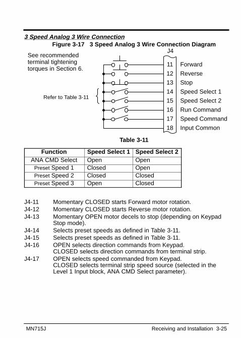
3 Speed Analog 3 Wire ConnectionFigure 3-17 3 Speed Analog 3 Wire Connection Diagram
11
12
13
14
15
16
17
18
Forward
Reverse
Stop
Speed Select 1
Speed Select 2
Run Command
Speed Command
Input Common
J4
Refer to Table 3-11
See recommended terminal tightening torques in Section 6.
Table 3-11
Function Speed Select 1 Speed Select 2ANA CMD Select Open Open
Preset Speed 1 Closed OpenPreset Speed 2 Closed ClosedPreset Speed 3 Open Closed
J4-11 Momentary CLOSED starts Forward motor rotation.J4-12 Momentary CLOSED starts Reverse motor rotation.J4-13 Momentary OPEN motor decels to stop (depending on Keypad
Stop mode).J4-14 Selects preset speeds as defined in Table 3-11.J4-15 Selects preset speeds as defined in Table 3-11.J4-16 OPEN selects direction commands from Keypad.
CLOSED selects direction commands from terminal strip.J4-17 OPEN selects speed commanded from Keypad.
CLOSED selects terminal strip speed source (selected in theLevel 1 Input block, ANA CMD Select parameter).

3-26 Receiving and Installation MN715J
EPOT 2 Wire ConnectionFigure 3-18 Electronic POT 2 Wire Connection Diagram
11
12
13
14
15
16
17
18
Forward
Reverse
EPOT/CMD Select
Accel/Decel Select
Increase
Decrease
External Trip
Input CommonRefer to Figure 3-9.
J4See recommended terminal tightening torques in Section 6.
J4-11 OPEN motor decels to stop (depending on Keypad Stop mode).CLOSED to enable operation in the Forward direction.
J4-12 OPEN motor decels to stop (depending on Keypad Stop mode).CLOSED to enable operation in the Reverse direction.
J4-13 OPEN for normal speed mode. Terminal strip speed source isselected in the Level 1 Input block, ANA CMD Select parameter.CLOSED to enable the Electronic Potentiometer Mode.
J4-14 OPEN selects ACC / DEC / S-CURVE group 1. CLOSED selects group 2.
J4-15 Momentary CLOSED increases motor speed while closed.J4-16 Momentary CLOSED decreases motor speed while closed.J4-17 If J4-17 is connected, you must set Level 2 Protection block,
External Trip to “ON” to activate the opto input.OPEN causes an external trip fault. The control will disable andthe motor coasts to a stop. An external trip fault is displayed (alsologged in the fault log). CLOSED allows normal operation.
MN715J Receiving and Installation 3-27
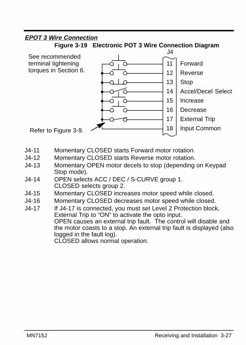
EPOT 3 Wire ConnectionFigure 3-19 Electronic POT 3 Wire Connection Diagram
11
12
13
14
15
16
17
18
Forward
Reverse
Stop
Accel/Decel Select
Increase
Decrease
External Trip
Input CommonRefer to Figure 3-9.
J4See recommended terminal tightening torques in Section 6.
J4-11 Momentary CLOSED starts Forward motor rotation.J4-12 Momentary CLOSED starts Reverse motor rotation.J4-13 Momentary OPEN motor decels to stop (depending on Keypad
Stop mode).J4-14 OPEN selects ACC / DEC / S-CURVE group 1.
CLOSED selects group 2.J4-15 Momentary CLOSED increases motor speed while closed.J4-16 Momentary CLOSED decreases motor speed while closed.J4-17 If J4-17 is connected, you must set Level 2 Protection block,
External Trip to “ON” to activate the opto input.OPEN causes an external trip fault. The control will disable andthe motor coasts to a stop. An external trip fault is displayed (alsologged in the fault log). CLOSED allows normal operation.

3-28 Receiving and Installation MN715J
Pre-Operation Checklist Check of electrical items.1. Verify AC line voltage at source matches control rating.2. Inspect all power connections for accuracy, workmanship and tightness
as well as compliance to codes.3. Verify control and motor are grounded to each other and the control is
connected to earth ground.4. Check all signal wiring for accuracy.5. Be certain all brake coils, contactors and relay coils have noise
suppression. This should be an R-C filter for AC coils and reversebiased diodes for DC coils. MOV type transient suppression is notadequate for noise suppression.
Check of Motor and Couplings1. Verify freedom of motion of motor shaft.2. Verify that all motor couplings are tight without backlash.3. If holding brakes are used, verify they are properly adjusted to fully
release and set to the desired torque value.Power-up Procedure1. Turn power on. Be sure no faults are displayed on the keypad display.2. Set the Level 1 Input block, Operating Mode to “Keypad”.3. Set the Level 2 Output Limits block, “MIN Output FREQ” parameter.4. Set the Level 2 Output Limits block, “MAX Output FREQ” parameter.5. If the desired peak current limit setting is not correct, set the Level 2
Output Limits block, “PK Current Limit” parameter as desired.6. Enter the following motor data in the Level 2 Motor Data block
parameters:Motor Rated Amps (FLA)Motor Rated Speed (base speed)Motor Mag Amps (no load current)
7. If External Dynamic Brake hardware is used, set the Level 2 BrakeAdjust block parameters as desired.
8. Set the Level 1 V/HZ Boost block, “V/HZ Profile” parameter for thecorrect V/Hz ratio for your application.
9. If the load is a high initial starting torque type, the torque boost andAccel time may need to be increased. Set the Level 1 V/HZ Boostblock, “Torque Boost” and the Level 1 Accel/Decel Rate block, “ACCELTIME #1” as required.
10. Select and program additional parameters to suit your application.
The control is now ready for use in keypad mode. The terminal strip wiringmay be changed and different parameter values used for another operatingmode.
Section 4Programming and Operation
MN715J Programming and Operation 4-1
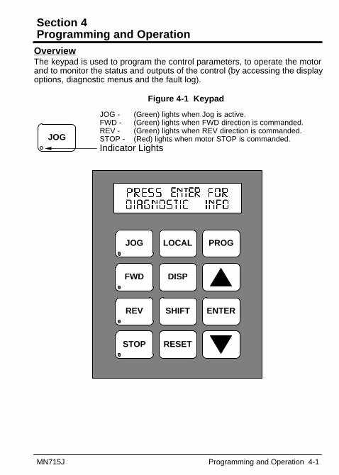
OverviewThe keypad is used to program the control parameters, to operate the motorand to monitor the status and outputs of the control (by accessing the displayoptions, diagnostic menus and the fault log).
Figure 4-1 Keypad
JOG - (Green) lights when Jog is active.FWD - (Green) lights when FWD direction is commanded.REV - (Green) lights when REV direction is commanded.STOP - (Red) lights when motor STOP is commanded.Indicator Lights
JOG
FWD
REV
STOP
LOCAL
DISP
SHIFT
RESET
PROG
ENTER
JOG
4-2 Programming and Operation MN715J
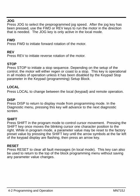
JOG Press JOG to select the preprogrammed jog speed. After the jog key hasbeen pressed, use the FWD or REV keys to run the motor in the directionthat is needed. The JOG key is only active in the local mode.
FWD Press FWD to initiate forward rotation of the motor.
REV Press REV to initiate reverse rotation of the motor.
STOP Press STOP to initiate a stop sequence. Depending on the setup of thecontrol, the motor will either regen or coast to a stop. This key is operationalin all modes of operation unless it has been disabled by the Keypad Stopparameter in the Keypad (programming) Setup Block.
LOCALPress LOCAL to change between the local (keypad) and remote operation.
DISP Press DISP to return to display mode from programming mode. In theDiagnostic menu, pressing this key will advance to the next diagnosticscreen.
SHIFT Press SHIFT in the program mode to control cursor movement. Pressing theSHIFT key once moves the blinking cursor one character position to theright. While in program mode, a parameter value may be reset to the factorypreset value by pressing the SHIFT key until the arrow symbols at the far leftof the keypad display are flashing, then press an arrow key. RESET Press RESET to clear all fault messages (in local mode). This key can alsobe used to return to the top of the block programming menu without savingany parameter value changes.
MN715J Programming and Operation 4-3
PROG Press PROG to enter the program mode to check or to edit a parametervalue.
� - (UP Arrow). Press � to change the value of the parameter being displayed. Pressing �increments the value to the next greater value. Also, when the fault log orparameter list is displayed, the � key will scroll upward through the list. Inthe local mode pressing the � key will increase motor speed to the nextgreater value.
ENTER Press ENTER to save parameter value changes and move back to theprevious level in the programming menu. In the display mode the ENTERkey is used to directly set the Local Speed Reference.
� - (Down Arrow)Press � to change the value of the parameter being displayed. Pressing �decrements the value to the next lesser value. Also, when the fault log orparameter list is displayed, the � key will scroll downward through the list.In the local mode pressing the � key will decrease motor speed to the nextlesser value.
4-4 Programming and Operation MN715J
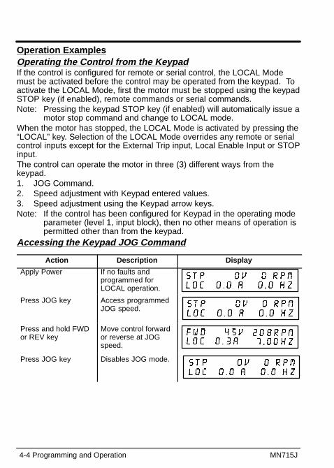
Operation ExamplesOperating the Control from the KeypadIf the control is configured for remote or serial control, the LOCAL Modemust be activated before the control may be operated from the keypad. Toactivate the LOCAL Mode, first the motor must be stopped using the keypadSTOP key (if enabled), remote commands or serial commands.Note: Pressing the keypad STOP key (if enabled) will automatically issue a
motor stop command and change to LOCAL mode.When the motor has stopped, the LOCAL Mode is activated by pressing the“LOCAL” key. Selection of the LOCAL Mode overrides any remote or serialcontrol inputs except for the External Trip input, Local Enable Input or STOPinput.The control can operate the motor in three (3) different ways from thekeypad.1. JOG Command.2. Speed adjustment with Keypad entered values.3. Speed adjustment using the Keypad arrow keys.Note: If the control has been configured for Keypad in the operating mode
parameter (level 1, input block), then no other means of operation ispermitted other than from the keypad.
Accessing the Keypad JOG Command
Action Description Display
Apply Power If no faults andprogrammed forLOCAL operation.
Press JOG key Access programmedJOG speed.
Press and hold FWDor REV key
Move control forwardor reverse at JOGspeed.
Press JOG key Disables JOG mode.
MN715J Programming and Operation 4-5
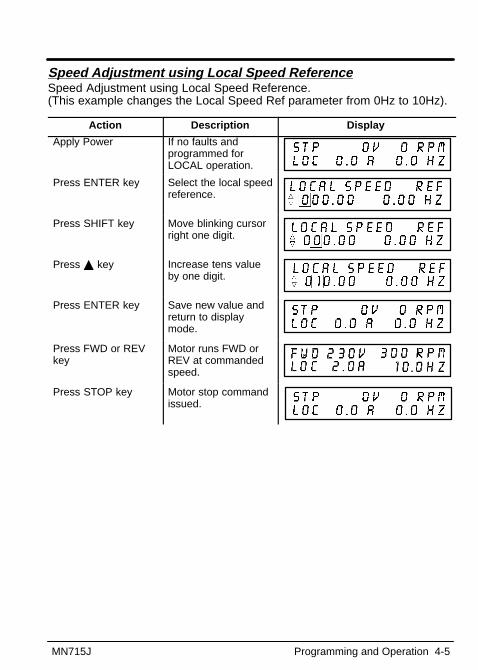
Speed Adjustment using Local Speed ReferenceSpeed Adjustment using Local Speed Reference. (This example changes the Local Speed Ref parameter from 0Hz to 10Hz).
Action Description Display
Apply Power If no faults andprogrammed forLOCAL operation.
Press ENTER key Select the local speedreference.
Press SHIFT key Move blinking cursorright one digit.
Press � key Increase tens valueby one digit.
Press ENTER key Save new value andreturn to displaymode.
Press FWD or REVkey
Motor runs FWD orREV at commandedspeed.
Press STOP key Motor stop commandissued.

4-6 Programming and Operation MN715J
Speed Adjustment using Arrow Keys
Action Description DisplayApply Power If no faults and
programmed forLOCAL operation.
Press FWD or REVkey
Motor runs FWD orREV at selectedspeed.
Press � key Increase motorspeed.
Press � key Decrease motorspeed.
Press � key Increase motorspeed.
Press STOP key Motor stopcommand issued.
Press FWD or REVkey
Motor runs FWD orREV atcommandedspeed.
Press STOP key Motor stopcommand issued.

MN715J Programming and Operation 4-7
Display ModeDuring normal operation the controller is in the display mode and the keypaddisplays the status of the control. Several output status values can bemonitored.
Motor StatusControl Operation
Output StatusValue and Units
The display mode also gives the user the ability to view diagnosticinformation and the fault log.
Adjusting Display ContrastWhen AC power is applied to the control the keypad should display thestatus of the control. If there is no display visible, use the followingprocedure to adjust the display.
Action Description Display
Apply Power No visible display
Press DISP Key Places control indisplay mode
Press SHIFT SHIFT Allows displaycontrast adjustment
Press � or � Key Adjusts displayintensity
Press ENTER Saves level ofcontrast and exits todisplay mode

4-8 Programming and Operation MN715J
Display Screens
Action Description Display
Apply Power Display of mode &drive status.
Press DISP key The fault log block.
Press DISP key The diagnosticinformation block.
Press DISP key The modifiedparameters block.
Press DISP key Display of outputfrequency.
Press DISP key Display of motorspeed (based onoutput frequency).
Press DISP key Display of motorcurrent.
Press DISP key Display of motorvoltage.
MN715J Programming and Operation 4-9
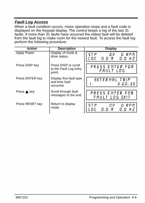
Fault Log AccessWhen a fault condition occurs, motor operation stops and a fault code isdisplayed on the Keypad display. The control keeps a log of the last 31faults. If more than 31 faults have occurred the oldest fault will be deletedfrom the fault log to make room for the newest fault. To access the fault logperform the following procedure:
Action Description DisplayApply Power Display of mode &
drive status.
Press DISP key Press DISP to scrollto the Fault Log entrypoint.
Press ENTER key Display first fault typeand time faultoccurred.
Press � key Scroll through faultmessages to the end.
Press RESET key Return to displaymode.

4-10 Programming and Operation MN715J
Diagnostic Information Access
Action Description DisplayApply Power Display of mode & drive
status.
Press DISP keyseveral times
Scroll to Diagnostic Infoentry point.
Press ENTER key Access diagnosticinformation.
Press DISP key Control temperature.
25.0
Press DISP key Bus voltage.
Press DISP key PWM Frequency.
2500
Press DISP key % overload currentremaining.
Press DISP key Display of HP, voltage,rated peak &continuous current.
Press DISP key Real time opto inputs &relay outputs states.(0=Open, 1=Closed)
Press DISP key Display of AnalogInputs.
Press DISP key (Displayed in ProcessControl mode only)Display of“Proportional”, “Integral”and “Derivative” terms.
Press DISP key (Displayed in ProcessControl mode only)Display of“Feedforward” (1st line),“Setpoint” and“Feedback” equiv. freq.(2nd line, left to right)
Continued on next page

MN715J Programming and Operation 4-11
Diagnostic Information Access Continued
Action Description DisplayPress DISP key Operating time.
Press DISP key Display of softwareversion.
Press DISP key Displays exit choice. Press ENTER to exit.
Note: In Diagnostic mode only, press DISP to display next item or pressSHIFT to display previous item.
4-12 Programming and Operation MN715J
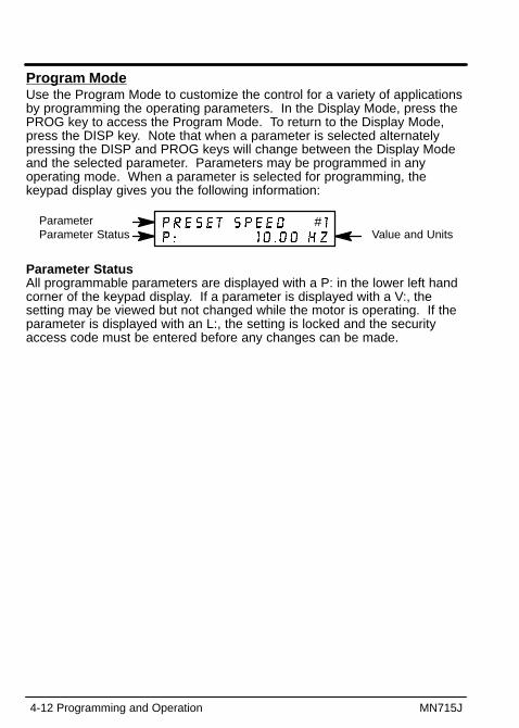
Program ModeUse the Program Mode to customize the control for a variety of applicationsby programming the operating parameters. In the Display Mode, press thePROG key to access the Program Mode. To return to the Display Mode,press the DISP key. Note that when a parameter is selected alternatelypressing the DISP and PROG keys will change between the Display Modeand the selected parameter. Parameters may be programmed in anyoperating mode. When a parameter is selected for programming, thekeypad display gives you the following information:
Parameter StatusParameter
Value and Units#
Parameter StatusAll programmable parameters are displayed with a P: in the lower left handcorner of the keypad display. If a parameter is displayed with a V:, thesetting may be viewed but not changed while the motor is operating. If theparameter is displayed with an L:, the setting is locked and the securityaccess code must be entered before any changes can be made.

MN715J Programming and Operation 4-13
Parameter Blocks Access for ProgrammingUse the following procedure to access parameter blocks to program thecontrol.
Action Description Display
Apply Power If no faults andprogrammed forLOCAL operation.
If no faults andprogrammed forREMOTE operation.
If fault is displayed,refer to theTroubleshootingsection of thismanual.
Press PROG key
Press � or � key Scroll to theACCEL/DECEL block.
Press � or � key Scroll to the Level 2Block.
Press ENTER key First level 2 blockdisplay.
Press � or � key Scroll toProgramming Exitmenu.
Press ENTER key Return to displaymode.

4-14 Programming and Operation MN715J
Changing Parameter ValuesUse the following procedure to program or change a parameter value.
Action Description Display
Apply Power If no faults andprogrammed forLOCAL operation.
Press PROG key Access programmingmode.
Press � or � key Scroll to Level 1 InputBlock.
Press ENTER key Access Input Block.
Press ENTER key Access OperatingMode.
Press � key Scroll to make yourselection.
Press ENTER Save selection tomemory.
Press � key Scroll to menu exit.
Press ENTER key Return to Input Block.
Press � or � key Scroll toProgramming Exitmenu.
Press ENTER key Return to displaymode.
MN715J Programming and Operation 4-15
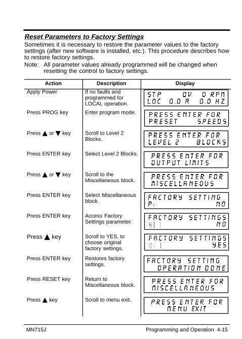
Reset Parameters to Factory SettingsSometimes it is necessary to restore the parameter values to the factorysettings (after new software is installed, etc.). This procedure describes howto restore factory settings.Note: All parameter values already programmed will be changed when
resetting the control to factory settings.
Action Description Display
Apply Power If no faults andprogrammed forLOCAL operation.
Press PROG key Enter program mode.
Press � or � key Scroll to Level 2Blocks.
Press ENTER key Select Level 2 Blocks.
Press � or � key Scroll to theMiscellaneous block.
Press ENTER key Select Miscellaneousblock.
Press ENTER key Access FactorySettings parameter.
Press � key Scroll to YES, tochoose originalfactory settings.
Press ENTER key Restores factorysettings.
Press RESET key Return toMiscellaneous block.
Press � key Scroll to menu exit.
4-16 Programming and Operation MN715J
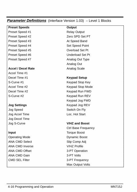
Parameter Definitions (Interface Version 1.03) – Level 1 Blocks
Preset Speeds Output
Preset Speed #1 Relay Output
Preset Speed #2 Zero SPD Set PT
Preset Speed #3 At Speed Band
Preset Speed #4 Set Speed Point
Preset Speed #5 Overload Set Pt
Preset Speed #6 Underload Set Pt
Preset Speed #7 Analog Out Type
Analog Out
Accel / Decel Rate Analog Scale
Accel Time #1
Decel Time #1 Keypad Setup
S-Curve #1 Keypad Stop Key
Accel Time #2 Keypad Stop Mode
Decel Time #2 Keypad Run FWD
S-Curve #2 Keypad Run REV
Keypad Jog FWD
Jog Settings Keypad Jog REV
Jog Speed Switch On Fly
Jog Accel Time Loc. Hot Start
Jog Decel Time
Jog S-Curve V/HZ and Boost
Ctrl Base Frequency
Input Torque Boost
Operating Mode Dynamic Boost
ANA CMD Select Slip Comp Adj
ANA CMD Inverse V/HZ Profile
ANA CMD Offset 3-PT Operation
ANA CMD Gain 3-PT Volts
CMD SEL Filter 3-PT Frequency
Max Output Volts
MN715J Programming and Operation 4-17
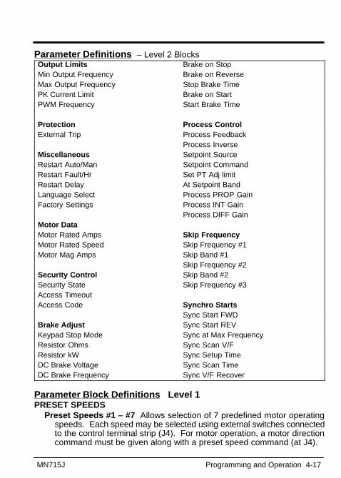
Parameter Definitions – Level 2 BlocksOutput Limits Brake on StopMin Output Frequency Brake on ReverseMax Output Frequency Stop Brake TimePK Current Limit Brake on StartPWM Frequency Start Brake Time
Protection Process ControlExternal Trip Process Feedback
Process InverseMiscellaneous Setpoint SourceRestart Auto/Man Setpoint CommandRestart Fault/Hr Set PT Adj limitRestart Delay At Setpoint BandLanguage Select Process PROP GainFactory Settings Process INT Gain
Process DIFF GainMotor DataMotor Rated Amps Skip FrequencyMotor Rated Speed Skip Frequency #1Motor Mag Amps Skip Band #1
Skip Frequency #2Security Control Skip Band #2Security State Skip Frequency #3Access TimeoutAccess Code Synchro Starts
Sync Start FWDBrake Adjust Sync Start REVKeypad Stop Mode Sync at Max FrequencyResistor Ohms Sync Scan V/FResistor kW Sync Setup TimeDC Brake Voltage Sync Scan TimeDC Brake Frequency Sync V/F Recover
Parameter Block Definitions Level 1PRESET SPEEDS
Preset Speeds #1 – #7 Allows selection of 7 predefined motor operatingspeeds. Each speed may be selected using external switches connectedto the control terminal strip (J4). For motor operation, a motor directioncommand must be given along with a preset speed command (at J4).
4-18 Programming and Operation MN715J
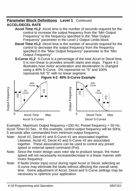
Parameter Block Definitions Level 1 ContinuedACCEL/DECEL RATE
Accel Time #1,2 Accel time is the number of seconds required for thecontrol to increase the output frequency from the “Min OutputFrequency” to the frequency specified in the “Max OutputFrequency” parameter in the Level 2 Output Limits block.
Decel Time #1,2 Decel time is the number of seconds required for thecontrol to decrease the output frequency from the frequencyspecified in the “Max Output frequency” parameter to the “MinOutput Frequency”.
S-Curve #1,2 S-Curve is a percentage of the total Accel or Decel time.It is non-linear to provides smooth starts and stops. Figure 4-2illustrates how motor acceleration and deceleration is changedusing a 40% S-Curve. 0% represents no “S” and 100%represents full “S” with no linear segment.
Figure 4-2 40% S-Curve Example
Out
put
Fre
quen
cy
Accel Time0 MaxAccel S-Curves
20%
20%
0%Curve
40%Curve
Out
put
Fre
quen
cy
Decel Time0 MaxDecel S-Curves
20%
20%
0%Curve
40%Curve
Example: Maximum Output frequency =100 Hz; Preset frequency = 50 Hz,Accel Time=10 Sec. In this example, control output frequency will be 50Hz,5 seconds after commanded from minimum output frequency.Note: Accel #1, Decel #1 and S-Curve #1 are associated together.
Likewise, Accel #2, Decel #2 and S-Curve #2 are associatedtogether. These associations can be used to control any presetspeed or external speed command (Pot).
Note: Since the motor design uses rotor slip to produce torque, the motorspeed will not necessarily increase/decrease in a linear manner withmotor frequency.
Note: If faults (motor trips) occur during rapid Accel or Decel, selecting anS-curve may eliminate the faults without affecting the overall ramptime. Some adjustment of Accel, Decel and S-Curve settings may benecessary to optimize your application.

MN715J Programming and Operation 4-19
Parameter Block Definitions Level 1 ContinuedJOG SETTINGS
Jog Speed Jog Speed is the commanded frequency used during jog.Jog speed can be initiated from the keypad or terminal strip. Atthe keypad, first press the JOG key then either the FWD or REVkey.
Jog Accel Time is the Accel Time used during jog.Jog Decel Time is the Decel Time used during jog.Jog S-Curve is the S-Curve used during jog.
INPUTOperating Mode The “Operating Modes” are: Keypad, Standard Run,
7 Speed, Fan Pump 2 Wire, Fan Pump 3 Wire, Process Control,3 Speed Analog 2 Wire, 3 Speed Analog 3 Wire, EPOT 2Wire,EPOT 3Wire. External connections to the control are made at theJ4 terminal strip (wiring diagrams are shown in Section 3).
ANA CMD Select Selects the external speed reference to be used.Potentiometer is the simplest method of speed control. Select
Potentiometer and connect a 5K� pot at J4-4, J4-5, andJ4-6.
0-5 or 0-10VDC input is selected when an input voltage signal isapplied to J4-7 and J4-8.
4-20mA or 0-20mA selection should be considered if longdistance is required between the external device and thecontrol. Current loop allows longer cable lengths at J4-7and J4-8 with less attenuation of the command signal.
None no external reference is selected.

4-20 Programming and Operation MN715J
Parameter Block Definitions Level 1 ContinuedINPUT
ANA CMD Inverse “ON” will cause a low input voltage (e.g. 0VDC) tobe a maximum motor speed command and a maximum inputvoltage (e.g. 10VDC) to be a low motor speed command. “OFF” will cause a low input voltage (e.g. 0VDC) to be a lowmotor speed command and a maximum input voltage (e.g.10VDC) to be a maximum motor speed command.
ANA CMD Offset Provides an offset to the Analog Input to minimizesignal drift. For example, if the minimum speed signal is 1VDC(instead of 0VDC) the ANA CMD Offset can be set to -10% so theminimum voltage input is seen by the control as 0VDC.
ANA CMD Gain Provides a gain factor for the analog speed referenceinput signal. For example, if the analog speed reference signal is0 - 9VDC, setting the ANA CMD Gain to 111% allows the controlto see 0 - 10VDC as the input signal.
ANA CMD Filter Provides filtering for the analog speed referenceinput signal. The greater the number (0 - 6) the more noisefiltering is provided. For faster response, use a smaller number.

MN715J Programming and Operation 4-21
Parameter Block Definitions Level 1 ContinuedOUTPUT
Relay Output N.O. and N.C. relay outputs that may be configured to anyof the following conditions:Ready Active when power is applied and no faults are present.Zero Speed Active when output frequency is less than the value of the
“Zero SPD Set Pt” Level 1 Output parameter.At Speed Band Active when output frequency is within the
commanded range defined by the “At Speed Band” Level 1Output parameter.
At Set Speed Active when output frequency is at or greater than the“Set Speed Point” Level 1 Output parameter.
Overload Output is active if the output current is greater than value ofthe Overload Set Point parameter value.
Underload Output is active if the output current is less than the valueof the Underload Set Point parameter.
Keypad Control Active when control is in local (keypad) control.Fault Active when a fault condition is present.Drive On Active when control is “Ready” and is being commanded to
operate the motor.Reverse Active when control is operating in the reverse direction.Process Error Active when the PID control loop process is outside the
range specified by the Level 2 Process Control block, AT Setpointband parameter.
Zero SPD Set PT The output frequency at which the zero speed relayoutput becomes active (turns on). When the output frequency is lessthan the Zero SPD Set PT, the relay output becomes active. This isuseful in applications where a motor brake will be interlocked into theoperation of the motor control.
At Speed Band A frequency band within which the at speed relay outputbecomes active (turns on). For example, if the at speed band is set to±5Hz the relay output becomes active when the output frequency to themotor is within 5Hz of the commanded motor frequency. This is usefulwhen another machine must not start (or stop) until the motor reachesoperating speed.
Set Speed Point The frequency at which the at set speed relay outputbecomes active (turns on). When the frequency is greater than the setspeed point parameter, the relay output becomes active. This is usefulwhen another machine must not start (or stop) until the motor exceedsa predetermined speed.
Overload Set Point When the output current exceeds this value, theoverload output is turned on.

4-22 Programming and Operation MN715J
Parameter Block Definitions Level 1 ContinuedOUTPUT Continued
Underload Set Point When the output current is less than this value,the underload output is turned on.
Analog OUT Type 0-10VDC, 0-5VDC, 4-20mA or 0-20mA.Analog Output Analog output that may be configured to represent
one of the following conditions:Frequency Represents the output frequency; where max output
= MAX Hz (slip freq. compensation is not included).Freq Command Represents the commanded frequency where
max output = MAX Hz.AC Current Represents the value of the output current where
max output = Full load current (ARMS).AC Voltage Represents the value of the output voltage where
max output = Control Input Voltage.Bus Voltage Represents motor power where half max output =
325VDC for 230VAC input (650VDC for 460VAC input).Control Temp Represents the heat sink temperature of the control
where max output = maximum heat sink temperature.Process Feedback Represents the process feedback signal where
max output = 100% feedback signal.Set Point Command Represents the setpoint command value
where max output = 100% commanded value.Zero Cal Output is minimum used to calibrate an external meter.100% Cal Output is maximum used to calibrate an external meter.
Analog Scale Scale factor for the Analog Output voltage. Useful to set the full scale range for external meters.
KEYPAD SETUPKeypad Stop Key Allows keypad STOP key to initiate motor stop
during remote or serial operation (if set to Remote ON). PressingSTOP initiates the stop command and automatically selects Localmode.
Keypad Stop Mode Causes the motor to coast to a stop or regen to astop for a stop command. In coast, the motor is turned off andallowed to coast to a stop. In regen, the voltage and frequency tothe motor is reduced at a rate set by the decel time.
Keypad Run FWD ON makes the keypad FWD key active in Local.Keypad Run REV ON makes the keypad REV key active in Local.Keypad Jog FWD ON makes the keypad FWD key active in Local Jog.Keypad Jog REV ON makes the keypad REV key active in Local Jog.
Continued on next page
MN715J Programming and Operation 4-23
Parameter Block Definitions Level 1 ContinuedKEYPAD SETUP Continued
Switch On Fly ON allows switching from Local to Remote mode orback without stopping the drive.
Loc. Hot Start ON allows the stop input to be used in keypad mode.
V/HZ AND BOOSTCTRL Base FREQ Represents the point on the V/Hz profile where
output voltage becomes constant with increasing outputfrequency. This is the point at which the motor changes fromconstant or variable torque to constant horsepower operation. Insome cases the Max Output Volts and CTRL Base Freq valuescan be manipulated to provide a wider constant torque or widerconstant horsepower speed range than is normally available withthe motor.
Torque Boost Adjusts the amount of motor starting torque. Theboost adjustment alters the output voltage to the motor from thenormal voltage value by increasing or decreasing the startingvoltage by fixed values as defined by the V/Hz profile. Thefactory setting is suitable for most applications. Increasing theboost may cause the motor to overheat. If adjustment is required,increase the boost in small increments until the motor shaft juststarts to rotate with maximum load applied.
Slip Comp Adjustment Compensates for varying load conditionsduring normal operation. This parameter sets the maximumallowable variation in output frequency under varying loadconditions (changes of output current). As motor currentincreases toward 100% of Motor Rated Amps, output frequency isautomatically increased to compensate for slip.
V/Hz Profile Sets the Volts/Frequency ratio of the control output (tothe motor) for all values of output voltage versus output frequencyup to the control base frequency. Because motor voltage isrelated to motor current, motor voltage can then be related tomotor torque. A change in the V/Hz profile can adjust how muchtorque is available from the motor at various speeds.3PT profile - allows two linear V/Hz segments by setting the V/Hz3PT Volts and V/Hz 3PT Frequency parameters. 0% to 100%squared reduced may be selected for the V/Hz profile. (0% =Linear V/Hz Profile.)These profiles are shown in Figure 4-3.

4-24 Programming and Operation MN715J
Parameter Block Definitions Level 1 ContinuedV/HZ AND BOOST Continued
3-PT Operation ON allows 3 point operation. OFF disables 3 pointoperation and the values of parameters V/Hz 3-PT Volts and V/Hz 3-PT Frequency are ignored.
V/Hz 3-PT Volts The output voltage associated with the 3PTFrequency parameter.
V/Hz 3-PT Frequency The output frequency associated with the 3PTVolts parameter.
Max Output Volts The maximum output voltage available to the motorfrom the control. This is useful if the motor rated voltage is lessthan the input line voltage. In some cases the Max Output Voltsand the CTRL Base Frequency parameter values can be adjustedto provide a wider constant torque or wider constant horsepowerspeed range than is normally available.
Figure 4-3 Volts/Hertz Profile
3 PTVolts
MaxOutput
TorqueBoost
Out
put V
olts
Output Frequency BaseFreq.
3 Point V/Hz CurveMaxOutput
TorqueBoost
Out
put V
olts
Output Frequency
BaseFreq.
3 PTFreq.
3 PT Volts
100%
0%
MN715J Programming and Operation 4-25
Parameter Block Definitions Level 2OUTPUT LIMITS
MIN Output Frequency The minimum output frequency to the motor.During operation, the output frequency will not be allowed to gobelow this value except for motor starts from 0 Hz or duringdynamic braking to a stop.
MAX Output Frequency The maximum output frequency to themotor.
PK Current Limit The maximum output (peak) current to the motor.Values above 100% of the rated current are available dependingupon the operating zone selected.
PWM Frequency The frequency that the output transistors areswitched. PWM should be as low as possible to minimize stresson the output transistors and motor windings. PWM frequency isalso referred to as “Carrier” frequency.
PROTECTIONExternal Trip
OFF - External Trip is Disabled. (Ignores J4-17).ON - External Trip is enabled. If a normally closed contact atJ4-17 (to J4-18) is opened, an External Trip fault will occur andcause the drive to shut down.
MISCELLANEOUSRestart Auto/Man
Manual If a fault occurs (or power loss), the control must bemanually reset to resume operation. Automatic - If a fault occurs (or power loss), the control willautomatically reset (after restart delay) to resume operation.
Restart Fault/Hr The maximum number of automatic restart attemptsbefore requiring a manual restart. After one hour without reachingthe maximum number of faults or if power is turned off and onagain, the fault count is reset to zero.
Restart Delay The amount of time allowed after a fault condition for anautomatic restart to occur. Useful to allow sufficient time to cleara fault before restart is attempted.
Language Select Selects English, Spanish, French, German, Italianor Portuguese characters for keypad display.
Factory Settings Restores factory settings for all parameter values. Select “YES” and press “ENTER” key to restore factory parametervalues. The keypad Display will show “Operation Done” thenreturn to “NO” when completed.
4-26 Programming and Operation MN715J
Parameter Block Definitions Level 2 ContinuedSECURITY CONTROL
Security StateOff - No security access code required to change parameter
values.Local Security - Requires security access code to be entered
before changes can be made using the Keypad.Serial Security - Requires security access code to be entered
before changes can be made using the 485 link.Total Security - Requires security access code to be entered
before changes can be made using the Keypad or seriallink.
Note: If security is set to local, serial or total you can press PROG andscroll through the parameter settings but you are not allowed tochange them unless you enter the correct access code.
Access Timeout The time in seconds the security access remainsenabled after leaving the programming mode. If you exit and goback into the program mode within this time limit, the securityAccess Code does not have to be re-entered. This timer startswhen leaving the program mode (by pressing DISP etc.).
Access Code A 4 digit code. You must know this code to changesecured Level 1 and Level 2 values.
Note: Please record your access code and store it in a safe place. If youcannot gain entry into parameter values to change a protectedparameter, please contact Baldor. Be prepared to give the 5 digitcode located on the lower right side of the Keypad Display at theEnter Code prompt.
MOTOR DATAMotor Rated Amps The rated current of the motor (listed on the motor
nameplate). If the motor current exceeds this value for a period oftime, an Overload fault will occur. If multiple motors are used onone control, add the Motor Rated Amps for all motors and enterthis value.
Motor Rated Speed The rated speed of the motor (listed on the motornameplate). If Motor Rated SPD = 1750 RPM and Motor RatedFreq = 60 Hz, the Keypad Display will show 1750 RPM at 60 Hzand 875 RPM at 30Hz.
Motor Rated Freq The rated frequency of the motor (listed on themotor nameplate).

MN715J Programming and Operation 4-27
Parameter Block Definitions Level 2 ContinuedBRAKE ADJUSTResistor Ohms The dynamic braking resistor value in ohms. Refer to the
dynamic braking manuals MN701 or MN782 or call Baldor for additionalinformation. If dynamic braking is not installed, enter zero.
Resistor Watts The dynamic braking resistor watts rating. Refer todynamic braking manual or call Baldor for additional information. Ifdynamic braking is not installed, enter zero.
DC Brake Voltage The amount of DC braking voltage applied to the motorwindings during a stop command. Increase this value for more brakingtorque during stops. The increased braking voltage may cause the motorto overheat for applications that require frequent starts/stops. Be carefulin selecting this value. The maximum DC Brake Voltage = (1.414)X(Max Output Volts).
DC Brake FREQ The output frequency (to the motor) at which DC injectionbraking will begin during Decel.
Brake on Stop If ON, DC injection braking will begin when a stop commandis issued. After a stop command, the DC brake voltage will be applied to themotor windings when the output frequency reaches the DC brake frequency.
Brake on Reverse If set to ON, DC injection braking will begin when thecontrol is commanded to drive the motor in the opposite direction.Braking continues until the motor is stopped. The motor will thenaccelerate in the opposite direction.
Stop Brake Time The maximum number of seconds that DC injection brakevoltage will be applied to the motor windings after a stop command. Afterthe time specified by this value, DC injection braking is automaticallyturned off. If DC injection braking starts at a frequency less than the DCbrake frequency parameter, the stop brake time is calculated as follows:
Brake Time � Stop Brake Time XOutput Frequency at Braking
DC Brake FrequencyBrake on Start If set to ON, turns DC injection braking ON for a period of
time (Start Brake Time) when a run command is issued. Braking willautomatically turn off and the motor will accelerate at the end of the startbrake time.
Start Brake Time The amount of time that DC injection braking will beapplied after a run command is issued. This will only occur if brake onstart is set to ON. Braking may cause the motor to overheat forapplications that require frequent starts/stops. Be careful in selecting thisvalue. The start brake time should be just long enough to ensure themotor shaft is not rotating when a start command is issued.

4-28 Programming and Operation MN715J
Parameter Block Definitions Level 2 ContinuedPROCESS CONTROL
Process Feedback The type of signal used for the process feedbackin the PID setpoint control loop.
Process Inverse OFF – The process feedback signal is not inverted(no polarity change).ON – Causes the process feedback signal to be inverted. Usedwith reverse acting processes that use a unipolar signal such as4-20mA. If “ON”, the PID loop will see a low value of the processfeedback signal as a high feedback signal and a high value of theprocess feedback signal as a low feedback signal.
Setpoint Source The source input reference signal type to which theprocess feedback will be compared. If “Setpoint CMD” isselected, a fixed value that is entered in the Setpoint Commandparameter (of the Level 2 Process Control block) will be used.
Setpoint Command The setpoint value for the PID loop that thecontrol will try to maintain. Used only when the setpoint sourceparameter is set to “Setpoint Command”.
Set PT ADJ Limit The maximum frequency correction value to beapplied to the motor (in response to the maximum process error).For example, if the max output frequency is 60 Hz, the setpointadjustment limit is 20%, the process error is 100% and themaximum speed the motor will run in response to the setpointfeedback error is ±12 Hz. (60Hz x 20% = 12Hz or a total of 24 Hztotal output band-width centered around the effective setpointfrequency).
At Setpoint Band The operating band within which the At Setpointopto output is active (turned ON). This feature indicates when theprocess is within the desired setpoint range. For example, if thesetpoint source is 0-10VDC and the at setpoint band value is10%, the at setpoint opto output will turn on if the process is within(10 x 10% = 1) ±1VDC of the setpoint.
Process PROP Gain Sets the PID loop proportional gain or how muchadjustment to motor speed is made to bring the process to thesetpoint.
Process INT Gain The PID loop Integral gain or how much adjustmentto motor speed is made to correct for long term error.
Process DIFF Gain The PID loop differential gain or how muchadjustment to motor speed is made for short term error.

MN715J Programming and Operation 4-29
Parameter Block Definitions Level 2 ContinuedSKIP FREQUENCY
Skip Frequency (#1, #2 and #3) The center frequency of thefrequency band to skip or treat as a speed command dead-band.
Skip Band (#1, #2 and #3) The width of the band centered about theSkip Frequency. For example, if Skip Frequency #1 is set to20Hz and Skip Band #1 is set to 5Hz, continuous operation is notallowed in the dead-band of 15Hz to 25Hz.
Note: Three bands can be defined independently or the three values can beselected to skip one wide frequency band.
SYNCHRO STARTSSync Start FWD Synchro Starts scans in the forward direction.Sync Start REV Synchro Starts scans in the reverse direction.Sync at Max Freq When set to ON, Synchro Starts begins scanning
at the maximum output frequency. When set to OFF, SynchroStarts begins scanning at the command frequency.
Sync Scan V/F Sets the Volts/Hertz ratio for the Synchro Startsfeature as a percentage of the V/Hz ratio defined by the MaxOutput Volts/Base Frequency. This Sync Scan V/F percentagevalue is multiplied by the Max Output Volts/Base Frequencyvalue. If this value is too high, the inverter may fault onOver-Current.
Sync Setup Time The time for the inverter to ramp the output voltagefrom zero to the voltage that corresponds to the frequency set bythe “Sync at Max Freq” parameter. A 0.5 second delay before theramp begins is not included in this time. If the Synchro Startsfeature is not operating quickly enough, decrease the Sync SetupTime value.
Sync Scan Time The time allowed for Synchro Starts to scan anddetect rotor frequency. Generally, the shorter the Sync Scan Timethe more likely a false Synchro Starts will be detected. This valueshould be set high enough to eliminate false Synchro Starts.
Sync V/F Recover The time allowed to ramp up the output voltagefrom the Synchro Starts scan voltage to the normal outputvoltage. This occurs after the synchronization frequency isdetected. The parameter value should be low enough to minimizeSynchro Starts time without causing the inverter to fault onOver-Current. m

4-30 Programming and Operation MN715J

Section 5Troubleshooting
MN715J Troubleshooting 5-1
The Baldor Series 15J Control requires very little maintenance, if any, andshould provide years of trouble free operation when installed and appliedcorrectly.Occasional visual inspection and cleaning should be considered to ensuretight wiring connections and to remove dust, dirt, or foreign debris which canreduce heat dissipation.Operational failures called faults are displayed on the keypad display as theyoccur. A comprehensive list of these faults and their meaning is provided inthis section. The procedure to access the fault log and diagnosticinformation is also provided.Before consulting the factory, check that all power and control wiring iscorrect and installed per the recommendations given in this manual.
No Keypad Display - Display Contrast AdjustmentAt power up, the display could be blank if the contrast is improperly set. Thefollowing procedure is used to adjust the display contrast. Be sure keypad isplugged into the keypad connector on the main control board.
Action Description Display
Apply Power No visible display
Press DISP Key Places control indisplay mode
Press SHIFT SHIFT Allows displaycontrast adjustment
Press � or � Key Adjusts displayintensity
Press ENTER Saves level ofcontrast and exits todisplay mode

5-2 Troubleshooting MN715J
Wrong Language SelectionThe following procedure is used to set the language used by the keypaddisplay. The table on this page shows the selections in each of thelanguages.
Action Description Display
Apply Power
Press SHIFT
Press PROG Displays selectedlanguage.
Press ENTER Allows languageselection.
Press � or � Key Scroll to the desiredlanguage.
Press ENTER Saves selection andexits to display mode.
English Spanish French German Italian Portuguese
LANGUAGE
SELECT
SELECCION
IDIOMA
SELECTION
LANGUE
SPRACHAUS�
WAHL
SELEZIONE
LINGUA
SELE/
LINGUAGEM
ENGLISH INGLES ANGLAIS ENGLISCH INGLESE INGLES
SPANISH ESPANOL ESPAGNOL SPANISCH SPAGNOLO ESPANHOL
FRENCH FRANCES FRANCAIS FRANZOSISCH FRANCESE FRANCES
GERMAN ALEMAN ALLEMAND DEUTCH TEDESCO ALEMAO
ITALIAN ITALIANO ITALIEN ITALIENISCH ITALIANO ITALIANO
PORTUGUESE PORTUGUES PORTUGAIS PORTUGIESISCH PORTOGHESE PORTUGUESES

MN715J Troubleshooting 5-3
Diagnostic Information Access
Action Description DisplayApply Power Display of mode & drive
status.
Press DISP keyseveral times
Scroll to Diagnostic Infoentry point.
Press ENTER key Access diagnosticinformation.
Press DISP key Control temperature.
25.0
Press DISP key Bus voltage.
Press DISP key PWM Frequency.
2500
Press DISP key % overload currentremaining.
Press DISP key Display of HP, voltage,rated peak &continuous current.
Press DISP key Real time opto inputs &relay outputs states.(0=Open, 1=Closed)
Press DISP key Display of AnalogInputs.
Press DISP key (Displayed in ProcessControl mode only)Display of“Proportional”, “Integral”and “Derivative” terms.
Press DISP key (Displayed in ProcessControl mode only)Display of“Feedforward” (1st line),“Setpoint” and“Feedback” equiv. freq.(2nd line, left to right)
Continued on next page
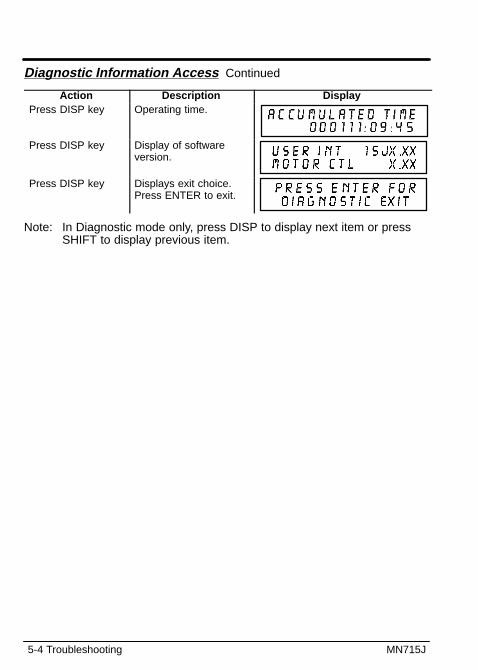
5-4 Troubleshooting MN715J
Diagnostic Information Access Continued
Action Description DisplayPress DISP key Operating time.
Press DISP key Display of softwareversion.
Press DISP key Displays exit choice. Press ENTER to exit.
Note: In Diagnostic mode only, press DISP to display next item or pressSHIFT to display previous item.
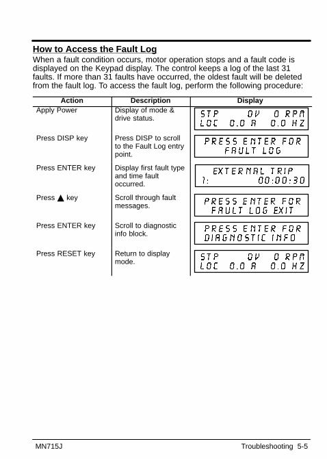
MN715J Troubleshooting 5-5
How to Access the Fault LogWhen a fault condition occurs, motor operation stops and a fault code isdisplayed on the Keypad display. The control keeps a log of the last 31faults. If more than 31 faults have occurred, the oldest fault will be deletedfrom the fault log. To access the fault log, perform the following procedure:
Action Description DisplayApply Power Display of mode &
drive status.
Press DISP key Press DISP to scrollto the Fault Log entrypoint.
Press ENTER key Display first fault typeand time faultoccurred.
Press � key Scroll through faultmessages.
Press ENTER key Scroll to diagnosticinfo block.
Press RESET key Return to displaymode.
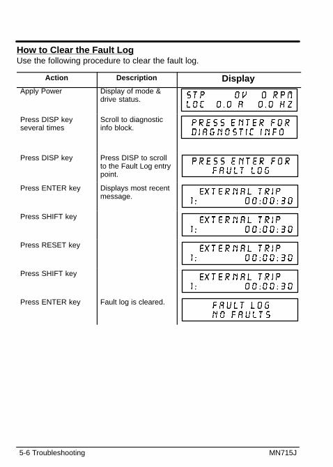
5-6 Troubleshooting MN715J
How to Clear the Fault LogUse the following procedure to clear the fault log.
Action Description DisplayApply Power Display of mode &
drive status.
Press DISP keyseveral times
Scroll to diagnosticinfo block.
Press DISP key Press DISP to scrollto the Fault Log entrypoint.
Press ENTER key Displays most recentmessage.
Press SHIFT key
Press RESET key
Press SHIFT key
Press ENTER key Fault log is cleared.
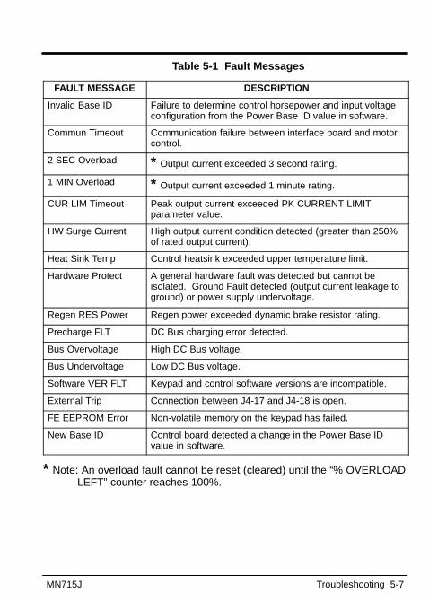
MN715J Troubleshooting 5-7
Table 5-1 Fault Messages
FAULT MESSAGE DESCRIPTION
Invalid Base ID Failure to determine control horsepower and input voltageconfiguration from the Power Base ID value in software.
Commun Timeout Communication failure between interface board and motorcontrol.
2 SEC Overload * Output current exceeded 3 second rating.
1 MIN Overload * Output current exceeded 1 minute rating.
CUR LIM Timeout Peak output current exceeded PK CURRENT LIMITparameter value.
HW Surge Current High output current condition detected (greater than 250%of rated output current).
Heat Sink Temp Control heatsink exceeded upper temperature limit.
Hardware Protect A general hardware fault was detected but cannot beisolated. Ground Fault detected (output current leakage toground) or power supply undervoltage.
Regen RES Power Regen power exceeded dynamic brake resistor rating.
Precharge FLT DC Bus charging error detected.
Bus Overvoltage High DC Bus voltage.
Bus Undervoltage Low DC Bus voltage.
Software VER FLT Keypad and control software versions are incompatible.
External Trip Connection between J4-17 and J4-18 is open.
FE EEPROM Error Non-volatile memory on the keypad has failed.
New Base ID Control board detected a change in the Power Base IDvalue in software.
* Note: An overload fault cannot be reset (cleared) until the “% OVERLOADLEFT” counter reaches 100%.
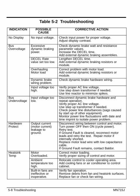
5-8 Troubleshooting MN715J
Table 5-2 Troubleshooting
INDICATION POSSIBLECAUSE
CORRECTIVE ACTION
No Display No input voltage. Check input power for proper voltage.Adjust display contrast.
BusOvervoltage
Excessivedynamic brakingpower.
Check dynamic brake watt and resistanceparameter values.Increase the DECEL time.Add external dynamic braking assemblies.
DECEL Ratevalue set too low.
Lengthen DECEL time.Add external dynamic braking resistors ormodule.
OverhaulingMotor load
Correct problem with motor load.Add external dynamic braking resistors ormodule.
Dynamic brakewiring problem.
Check dynamic brake hardware wiring.
Input voltage toohigh.
Verify proper AC line voltage.Use step down transformer if needed.Use line reactor to minimize spikes.
BusUndervoltage
Input voltage toolow.
Disconnect dynamic brake hardware andrepeat operation.Verify proper AC line voltage.Use step up transformer if needed.Check power line disturbances (sags causedby start up of other equipment).Monitor power line fluctuations with date andtime imprint to isolate power problem.
HardwareProtect
Output current(motor current)leakage toground.
Disconnect wiring between control and motor.Turn power OFF then ON (cycle power). Retry test. If Ground Fault is cleared, reconnect motorleads and retry the test. Repair motor ifinternally shorted.Replace motor lead wire with low capacitancecable.If Ground Fault remains, contact Baldor.
HeatsinkTemp
MotorOverloaded.
Correct motor loading.Verify proper sizing of control and motor.
Ambienttemperature toohigh.
Relocate control to cooler operating area.Add cooling fans or air conditioner to controlcabinet.
Built-in fans areineffective orinoperative.
Verify fan operation.Remove debris from fan and heatsink surfaces.Replace fan or check fan wiring.
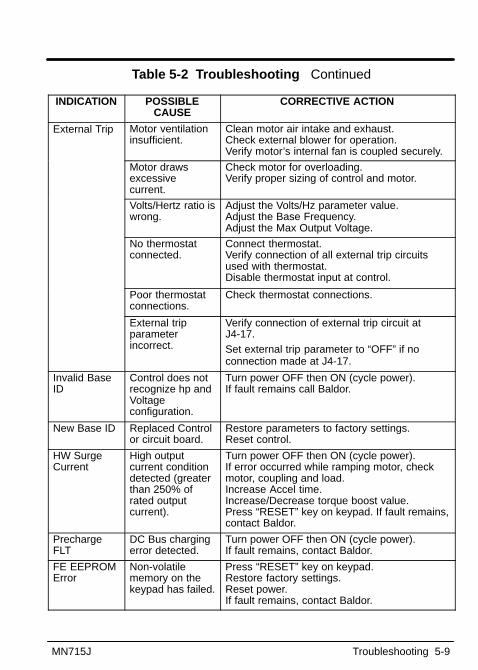
MN715J Troubleshooting 5-9
Table 5-2 Troubleshooting Continued
INDICATION POSSIBLECAUSE
CORRECTIVE ACTION
External Trip Motor ventilationinsufficient.
Clean motor air intake and exhaust.Check external blower for operation.Verify motor’s internal fan is coupled securely.
Motor drawsexcessivecurrent.
Check motor for overloading. Verify proper sizing of control and motor.
Volts/Hertz ratio iswrong.
Adjust the Volts/Hz parameter value.Adjust the Base Frequency.Adjust the Max Output Voltage.
No thermostatconnected.
Connect thermostat.Verify connection of all external trip circuitsused with thermostat.Disable thermostat input at control.
Poor thermostatconnections.
Check thermostat connections.
External tripparameterincorrect.
Verify connection of external trip circuit atJ4-17.Set external trip parameter to “OFF” if noconnection made at J4-17.
Invalid BaseID
Control does notrecognize hp andVoltageconfiguration.
Turn power OFF then ON (cycle power). If fault remains call Baldor.
New Base ID Replaced Controlor circuit board.
Restore parameters to factory settings.Reset control.
HW SurgeCurrent
High outputcurrent conditiondetected (greaterthan 250% ofrated outputcurrent).
Turn power OFF then ON (cycle power). If error occurred while ramping motor, checkmotor, coupling and load.Increase Accel time.Increase/Decrease torque boost value.Press “RESET” key on keypad. If fault remains,contact Baldor.
PrechargeFLT
DC Bus chargingerror detected.
Turn power OFF then ON (cycle power). If fault remains, contact Baldor.
FE EEPROMError
Non-volatilememory on thekeypad has failed.
Press “RESET” key on keypad. Restore factory settings.Reset power.If fault remains, contact Baldor.
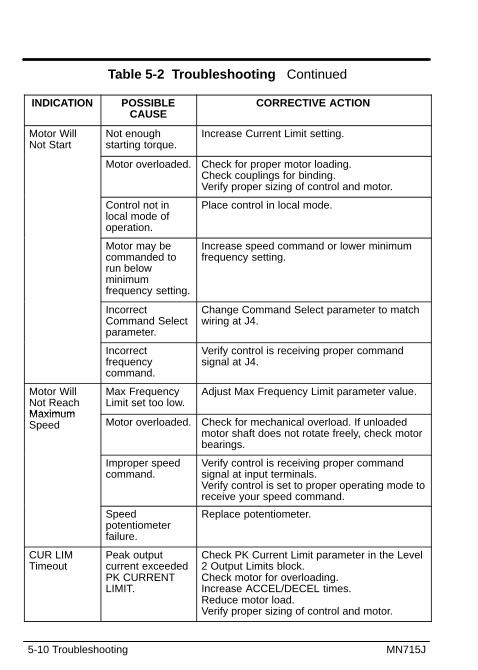
5-10 Troubleshooting MN715J
Table 5-2 Troubleshooting Continued
INDICATION POSSIBLECAUSE
CORRECTIVE ACTION
Motor WillNot Start
Not enoughstarting torque.
Increase Current Limit setting.
Motor overloaded. Check for proper motor loading.Check couplings for binding.Verify proper sizing of control and motor.
Control not inlocal mode ofoperation.
Place control in local mode.
Motor may becommanded torun belowminimumfrequency setting.
Increase speed command or lower minimumfrequency setting.
IncorrectCommand Selectparameter.
Change Command Select parameter to matchwiring at J4.
Incorrectfrequencycommand.
Verify control is receiving proper commandsignal at J4.
Motor WillNot ReachMaximum
Max FrequencyLimit set too low.
Adjust Max Frequency Limit parameter value.
MaximumSpeed Motor overloaded. Check for mechanical overload. If unloaded
motor shaft does not rotate freely, check motorbearings.
Improper speedcommand.
Verify control is receiving proper commandsignal at input terminals.Verify control is set to proper operating mode toreceive your speed command.
Speedpotentiometerfailure.
Replace potentiometer.
CUR LIMTimeout
Peak outputcurrent exceededPK CURRENTLIMIT.
Check PK Current Limit parameter in the Level2 Output Limits block.Check motor for overloading.Increase ACCEL/DECEL times.Reduce motor load.Verify proper sizing of control and motor.

MN715J Troubleshooting 5-11
Table 5-2 Troubleshooting ContinuedINDICATION POSSIBLE
CAUSECORRECTIVE ACTION
Motor will notstop rotation
MIN OutputSpeed parameterset too high.
Adjust MIN Output Speed parameter value.
Improper speedcommand.
Verify control is receiving proper commandsignal at input terminals.Verify control is set to receive your speedcommand.
Speedpotentiometerfailure.
Replace potentiometer.
Motor runsrough at lowspeed
Torque boost settoo high.
Adjust torque boost parameter value.g
speed Misalignment ofcoupling.
Check motor/load coupling alignment.
Faulty motor. Replace with a Baldor Motor.
Regen RESPower
Incorrect dynamicbrake parameter.
Check Resistor Ohms and Resistor Wattsparameters in the Level 2 Brake Adjust block.
Regen powerexceeded resistorrating.
Use resistor with a larger power rating.Increase Decel Time.
CommTimeout
Communicationfailure betweenkeypad and motorcontrol.
Verify connections of all signals and grounds.Press “RESET” key on keypad. If fault remains,contact Baldor.
SoftwareVER FLT
Keypad andcontrol softwareversions areincompatible.
Press “RESET” key on keypad. Reset power.If fault remains, contact Baldor.
3 SECOverload *
Output currentexceeded 3second rating.
Verify motor rated amperes parameter matchesFLA of motor.
Verify proper sizing of control and motor.If error occurred while ramping motor check
1 MINOverload *
Output currentexceeded 1minute rating.
If error occurred while ramping motor, checkmotor, coupling and load.
Increase ACCEL time.Increase/Decrease Torque Boost value.
* Note: An overload fault cannot be reset (cleared) until the “% OVERLOADLEFT” counter reaches 100%.

5-12 Troubleshooting MN715J
Electrical Noise ConsiderationsAll electronic devices are vulnerable to significant electronic interferencesignals (commonly called “Electrical Noise”). At the lowest level, noise cancause intermittent operating errors or faults. From a circuit standpoint, 5 or10 millivolts of noise may cause detrimental operation. For example, analogspeed inputs are often scaled at 5 to 10VDC maximum with a typicalresolution of one part in 1,000. Thus, noise of only 5 mV represents asubstantial error.At the extreme level, significant noise can cause damage to the drive.Therefore, it is advisable to prevent noise generation and to follow wiringpractices that prevent noise generated by other devices from reachingsensitive circuits. In a control, such circuits include inputs for speed, controllogic, and speed and position feedback, plus outputs to some indicators andcomputers.Relay and Contactor CoilsAmong the most common sources of noise are the ever-present coils ofcontactors and relays. When these highly inductive coil circuits are opened,transient conditions often generate spikes of several hundred volts in thecontrol circuit. These spikes can induce several volts of noise in an adjacentwire that runs parallel to a control-circuit wire.Figure 5-4 illustrates noise suppression for AC and DC operated coils.
Figure 5-4 Diode with DC Coil
AC Coil DC Coil
RC snubber
0.47 �fDiode
-
+
33 �
Wires between Controls and MotorsOutput leads from a typical 460 VAC drive controller contain rapid voltagerises created by power semiconductors switching 650V in less than amicrosecond, 1,000 to 10,000 times a second. These noise signals cancouple into sensitive drive circuits. If shielded pair cable is used, thecoupling is reduced by nearly 90% compared to unshielded cable.Even input AC power lines contain noise and can induce noise in adjacentwires. In some cases, line reactors may be required.

MN715J Troubleshooting 5-13
To prevent induced transient noise in signal wires, all motor leads and ACpower lines should be contained in rigid metal conduit, or flexible conduit.Do not place line conductors and load conductors in same conduit. Use oneconduit for 3 phase input wires and another conduit for the motor leads. Theconduits should be grounded to form a shield to contain the electrical noisewithin the conduit path. Signal wires - even ones in shielded cable shouldnever be placed in the conduit with motor power wires.Special Drive SituationsFor severe noise situations, it may be necessary to reduce transient voltagesin the wires to the motor by adding load reactors. Load reactors are installedbetween the control and motor.Reactors are typically 1% to 3% impedance and are designed for thefrequencies encountered in PWM drives. For maximum benefit, the reactorsshould be mounted in the drive enclosure with short leads between thecontrol and the reactors.Special Motor ConsiderationsMotor frames must also be grounded. As with control enclosures, motorsshould be grounded directly to plant ground with as short a ground wire aspossible. Capacitive coupling within the motor windings produces transientvoltages between the motor frame and ground. The severity of thesevoltages increases with the length of the ground wire. Installations with themotor and control mounted on a common frame, and with heavy groundwires less than 10 ft. long, rarely have a problem caused by thesemotor-generated transient voltages.Analog Signal Wires Analog signals generally originate from speed and torque controls,plus DC tachometers and process controllers. Reliability is oftenimproved by the following noise reduction techniques:• Use twisted-pair shielded wires with the shield grounded at the drive
end only.
• Route analog signal wires away from power or control wires (all otherwiring types).
• Cross power and control wires at right angles (90°) to minimize inductivenoise coupling.

5-14 Troubleshooting MN715J
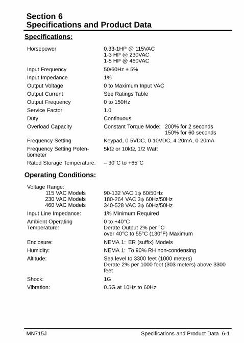
Section 6Specifications and Product Data
MN715J Specifications and Product Data 6-1
Specifications:
Horsepower 0.33-1HP @ 115VAC1-3 HP @ 230VAC1-5 HP @ 460VAC
Input Frequency 50/60Hz ± 5%
Input Impedance 1%
Output Voltage 0 to Maximum Input VAC
Output Current See Ratings Table
Output Frequency 0 to 150Hz
Service Factor 1.0
Duty Continuous
Overload Capacity Constant Torque Mode: 200% for 2 seconds150% for 60 seconds
Frequency Setting Keypad, 0-5VDC, 0-10VDC, 4-20mA, 0-20mA
Frequency Setting Poten-tiometer
5k� or 10k�, 1/2 Watt
Rated Storage Temperature: – 30°C to +65°C
Operating Conditions:
Voltage Range: 115 VAC Models230 VAC Models460 VAC Models
90-132 VAC 1� 60/50Hz180-264 VAC 3� 60Hz/50Hz340-528 VAC 3� 60Hz/50Hz
Input Line Impedance: 1% Minimum Required
Ambient Operating Temperature:
0 to +40°CDerate Output 2% per °Cover 40°C to 55°C (130°F) Maximum
Enclosure: NEMA 1: ER (suffix) Models
Humidity: NEMA 1: To 90% RH non-condensing
Altitude: Sea level to 3300 feet (1000 meters)Derate 2% per 1000 feet (303 meters) above 3300feet
Shock: 1G
Vibration: 0.5G at 10Hz to 60Hz
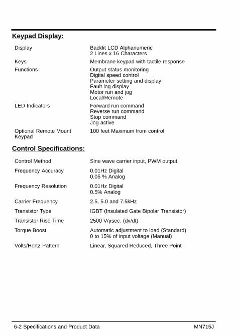
6-2 Specifications and Product Data MN715J
Keypad Display:
Display Backlit LCD Alphanumeric 2 Lines x 16 Characters
Keys Membrane keypad with tactile response
Functions Output status monitoringDigital speed controlParameter setting and displayFault log displayMotor run and jogLocal/Remote
LED Indicators Forward run commandReverse run commandStop commandJog active
Optional Remote Mount Keypad
100 feet Maximum from control
Control Specifications:
Control Method Sine wave carrier input, PWM output
Frequency Accuracy 0.01Hz Digital 0.05 % Analog
Frequency Resolution 0.01Hz Digital 0.5% Analog
Carrier Frequency 2.5, 5.0 and 7.5kHz
Transistor Type IGBT (Insulated Gate Bipolar Transistor)
Transistor Rise Time 2500 V/�sec. (dv/dt)
Torque Boost Automatic adjustment to load (Standard)0 to 15% of input voltage (Manual)
Volts/Hertz Pattern Linear, Squared Reduced, Three Point

MN715J Specifications and Product Data 6-3
Control Specifications: Continued
Accel/Decel Time 0 to 600 sec. for 2 assignable plus JOG
S-Curve Time 0 to 100%
Base Frequency 10 to 150Hz
Regenerative Braking Torque 50% with optional external braking resistor (–ER)
Jog Frequency 0 to Maximum frequency
Skip Frequency 0 to Maximum frequency in 3 zones.
Minimum Output Frequency 0 to 150Hz
Maximum Output Frequency 0 to 150Hz
Auto Restart Manual or Automatic
Slip Compensation 0 to 6Hz
Operating modes KeypadStandard Run7 SpeedFan Pump 2WireFan Pump 3WireProcess Control3SPD ANA 2WIRE3SPD ANA 3WIREEPOT – 2WIREEPOT – 3WIRE
Analog Inputs: (2 Inputs)
Potentiometer Input 0 - 10VDC
Differential Input Full ScaleRange
0-5VDC, 0-10VDC, 4-20mA, 0-20mA
Differential Input CommonMode Rejection
40db
Input Impedance 20k�
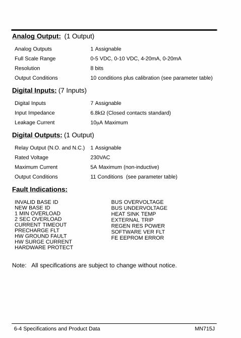
6-4 Specifications and Product Data MN715J
Analog Output: (1 Output)
Analog Outputs 1 Assignable
Full Scale Range 0-5 VDC, 0-10 VDC, 4-20mA, 0-20mA
Resolution 8 bits
Output Conditions 10 conditions plus calibration (see parameter table)
Digital Inputs: (7 Inputs)
Digital Inputs 7 Assignable
Input Impedance 6.8k� (Closed contacts standard)
Leakage Current 10�A Maximum
Digital Outputs: (1 Output)
Relay Output (N.O. and N.C.) 1 Assignable
Rated Voltage 230VAC
Maximum Current 5A Maximum (non-inductive)
Output Conditions 11 Conditions (see parameter table)
Fault Indications:
INVALID BASE IDNEW BASE ID1 MIN OVERLOAD2 SEC OVERLOADCURRENT TIMEOUTPRECHARGE FLTHW GROUND FAULTHW SURGE CURRENTHARDWARE PROTECT
BUS OVERVOLTAGEBUS UNDERVOLTAGEHEAT SINK TEMPEXTERNAL TRIPREGEN RES POWERSOFTWARE VER FLTFE EEPROM ERROR
Note: All specifications are subject to change without notice.
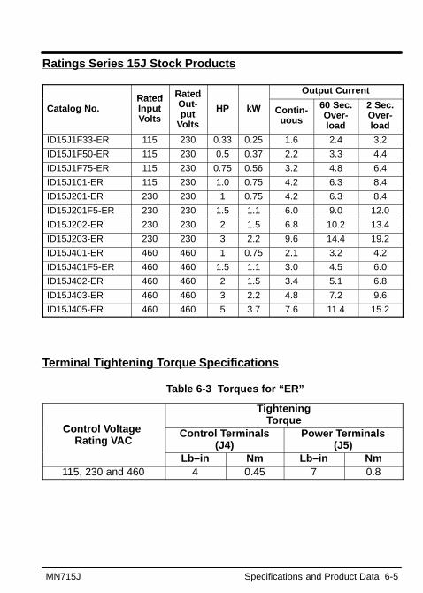
MN715J Specifications and Product Data 6-5
Ratings Series 15J Stock Products
Rated Rated Output Current
Catalog No.RatedInputVolts
RatedOut-put
Volts
HP kW Contin-uous
60 Sec.Over-load
2 Sec.Over-load
ID15J1F33-ER 115 230 0.33 0.25 1.6 2.4 3.2
ID15J1F50-ER 115 230 0.5 0.37 2.2 3.3 4.4
ID15J1F75-ER 115 230 0.75 0.56 3.2 4.8 6.4
ID15J101-ER 115 230 1.0 0.75 4.2 6.3 8.4
ID15J201-ER 230 230 1 0.75 4.2 6.3 8.4
ID15J201F5-ER 230 230 1.5 1.1 6.0 9.0 12.0
ID15J202-ER 230 230 2 1.5 6.8 10.2 13.4
ID15J203-ER 230 230 3 2.2 9.6 14.4 19.2
ID15J401-ER 460 460 1 0.75 2.1 3.2 4.2
ID15J401F5-ER 460 460 1.5 1.1 3.0 4.5 6.0
ID15J402-ER 460 460 2 1.5 3.4 5.1 6.8
ID15J403-ER 460 460 3 2.2 4.8 7.2 9.6
ID15J405-ER 460 460 5 3.7 7.6 11.4 15.2
Terminal Tightening Torque Specifications
Table 6-3 Torques for “ER”
Control Voltage
Tightening Torque
Control Voltage Rating VAC
Control Terminals(J4)
Power Terminals(J5)
Lb–in Nm Lb–in Nm115, 230 and 460 4 0.45 7 0.8

6-6 Specifications and Product Data MN715J
Mounting Dimensions
0.866(22)
0.20(5)
4.396(112)
7.210(183)
7.602(193)
4.834(123)
4.445(113)
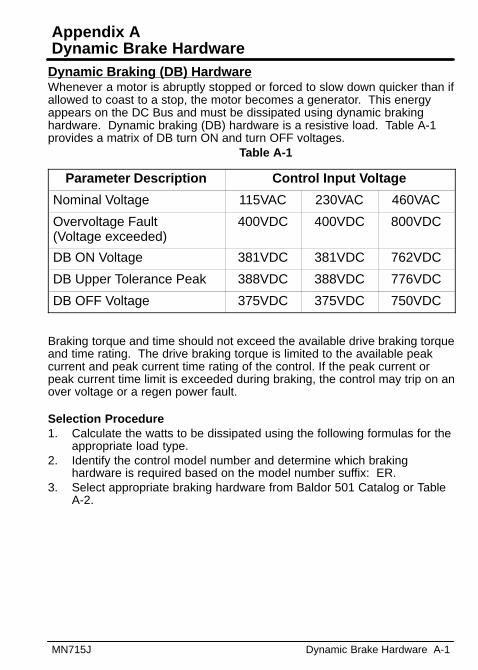
Appendix ADynamic Brake Hardware
MN715J Dynamic Brake Hardware A-1
Dynamic Braking (DB) HardwareWhenever a motor is abruptly stopped or forced to slow down quicker than ifallowed to coast to a stop, the motor becomes a generator. This energyappears on the DC Bus and must be dissipated using dynamic brakinghardware. Dynamic braking (DB) hardware is a resistive load. Table A-1provides a matrix of DB turn ON and turn OFF voltages.
Table A-1
Parameter Description Control Input Voltage
Nominal Voltage 115VAC 230VAC 460VAC
Overvoltage Fault (Voltage exceeded)
400VDC 400VDC 800VDC
DB ON Voltage 381VDC 381VDC 762VDC
DB Upper Tolerance Peak 388VDC 388VDC 776VDC
DB OFF Voltage 375VDC 375VDC 750VDC
Braking torque and time should not exceed the available drive braking torqueand time rating. The drive braking torque is limited to the available peakcurrent and peak current time rating of the control. If the peak current orpeak current time limit is exceeded during braking, the control may trip on anover voltage or a regen power fault.
Selection Procedure1. Calculate the watts to be dissipated using the following formulas for the
appropriate load type.2. Identify the control model number and determine which braking
hardware is required based on the model number suffix: ER.3. Select appropriate braking hardware from Baldor 501 Catalog or Table
A-2.
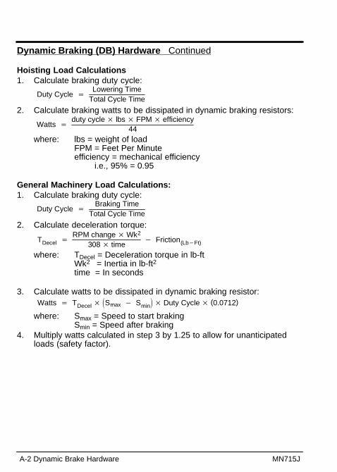
A-2 Dynamic Brake Hardware MN715J
Dynamic Braking (DB) Hardware Continued
Hoisting Load Calculations1. Calculate braking duty cycle:
Duty Cycle �
Lowering TimeTotal Cycle Time
2. Calculate braking watts to be dissipated in dynamic braking resistors:
Watts �duty cycle � lbs � FPM � efficiency
44where: lbs = weight of load
FPM = Feet Per Minuteefficiency = mechanical efficiency
i.e., 95% = 0.95
General Machinery Load Calculations:1. Calculate braking duty cycle:
Duty Cycle �
Braking TimeTotal Cycle Time
2. Calculate deceleration torque:
TDecel �
RPM change � Wk2
308 � time� Friction(Lb�Ft)
where: TDecel = Deceleration torque in lb-ft Wk2 = Inertia in lb-ft2 time = In seconds
3. Calculate watts to be dissipated in dynamic braking resistor:
Watts � TDecel � �Smax � Smin� � Duty Cycle � (0.0712)
where: Smax = Speed to start braking Smin = Speed after braking
4. Multiply watts calculated in step 3 by 1.25 to allow for unanticipatedloads (safety factor).

MN715J Dynamic Brake Hardware A-3
Dynamic Braking (DB) Hardware Continued15J Catalog Numbers with an “ER” SuffixThese controls include a factory-installed dynamic braking transistor. Ifdynamic braking is required, use an optional external RGA brake resistor.See RGA assemblies.RGA Assemblies include braking resistors completely assembled andmounted in a NEMA 1 enclosure. A listing of available RGA assemblies isprovided in Table A-2. The minimum resistance “Minimum Ohms” shown inthe table is the minimum resistor value that can be connected to the controlwithout causing damage to the internal dynamic brake transistor for ERcontrols.
115VAC controls must use 56 ohms or greater.230VAC controls must use 56 ohms or greater.460VAC controls must use 120 ohms or greater.
Table A-2 Dynamic Braking Resistor Assemblies (RGA)
Continuous Rated Watts
Minimum OhmsRated Watts
60 120 150
100 RGJ160 RGJ1120 RGJ1150
200 RGJ260 RGJ2120 RGJ2150
300 RGJ360 RGJ3120 RGJ3150
600 RGA660 RGA6120
1200 RGA1260 RGA12120
2400 RGA2460 RGA24120

A-4 Dynamic Brake Hardware MN715J

Appendix BParameter Values
MN715J Parameter Values B-1
Parameter Values (Interface Version 1.05) Level 1
PRESET SPEEDS Block
Parameter Adjustable Range FactorySetting
UserSetting
PRESET SPEED#1
0-Max Output Freq 0.00Hz
PRESET SPEED#2
0-Max Output Freq 0.00Hz
PRESET SPEED#3
0-Max Output Freq 0.00Hz
PRESET SPEED#4
0-Max Output Freq 0.00Hz
PRESET SPEED#5
0-Max Output Freq 0.00Hz
PRESET SPEED#6
0-Max Output Freq 0.00Hz
PRESET SPEED#7
0-Max Output Freq 0.00Hz
ACCEL/DECEL RATE Block
Parameter Adjustable Range FactorySetting
UserSetting
ACCEL TIME #1 000.1 to 600.0 Seconds 10.0S
DECEL TIME #1 000.1 to 600.0 Seconds 10.0S
S-CURVE #1 0 to 100% 0%
ACCEL TIME #2 000.1 to 600.0 Seconds 20.0S
DECEL TIME #2 000.1 to 600.0 Seconds 20.0S
S-CURVE #2 0 to 100% 0%

B-2 Parameter Values MN715J
JOG SETTINGS Block
Parameter Adjustable Range FactorySetting
UserSetting
JOG SPEED 0-Max Output Freq 7.00Hz
JOG ACCELTIME
000.1-600.0 Seconds 3.0S
JOG DECELTIME
000.1-600.0 Seconds 3.0S
JOG S-CURVE 0-100% 0%
INPUT Block
Parameter Adjustable Range FactorySetting
UserSetting
OPERATINGMODE
KeypadStandard Run7 SpeedFan Pump 2WireFan Pump 3WireProcess Control3SPD ANA 2WIRE3SPD ANA 3WIREEPOT 2WIREEPOT 3 WIRE
Keypad
ANA CMDSELECT
Potentiometer 0-10 Volts0-5 Volts4 TO 20 mA0 TO 20 mANone
Potentio-meter
ANA CMDINVERSE
OFF, ON OFF
ANA CMDOFFSET
-20.0 to +20.0% 0.0%
ANA CMD GAIN 80.0% to 120% 100.0%
ANA CMD FILTER 0-6 1

MN715J Parameter Values B-3
OUTPUT Block
Parameter Adjustable Range FactorySetting
UserSetting
RELAY OUTPUT ReadyZero Speed At Speed BandAt Set SpeedOverloadUnderloadKeypad ControlFaultDrive OnReverseProcess Error
Ready
ZERO SPD SETPT
0-Max Output Freq 6.00Hz
AT SPEED BAND 0-20.00Hz 20.00Hz
SET SPEEDPOINT
0-Max Output Freq 60.00Hz
OVERLOAD SETPT
0-PK Current Limit Factory Set
UNDERLOADSET PT
0-PK Current Limit Factory Set
ANALOG OUTTYPE
0-10 VOLTS, 0-5 VOLTS,4TO20mA, 0TO20mA
0-10 VOLTS
ANALOG OUT FrequencyFreq CommandAC CurrentAC VoltageBus VoltageControl TempProcess FeedbackSet Point CommandZero CAL100% CAL
Frequency
ANALOG SCALE 10-160% 100%

B-4 Parameter Values MN715J
KEYPAD SETUP Block
Parameter Adjustable Range FactorySetting
UserSetting
KEYPAD STOPKEY
Remote ON, Remote OFF Remote ON
KEYPAD STOPMODE
Regen BrakingCoast-No Regen
Regen Braking
KEYPAD RUNFWD
OFF, ON ON
KEYPAD RUNREV
OFF, ON ON
KEYPAD JOGFWD
OFF, ON ON
KEYPAD JOGREV
OFF, ON ON
SWITCH ON FLY OFF, ON OFF
LOC. HOT START OFF, ON OFF
V/HZ AND BOOST Block
Parameter Adjustable Range FactorySetting
UserSetting
CTRL BASEFREQUENCY
50.00-120.00Hz 60.00Hz
TORQUE BOOST 00.0 - 15.0% Factory Set
SLIP COMP ADJ 0.00 - 6.00Hz 0.00Hz
V/HZ PROFILE 0-100%0%=Linear Profile
0%
3–PTOPERATION
OFF, ON OFF
3–PT VOLTS 000.0-100.0% 0.0%
3–PTFREQUENCY
000.0-Ctrl Base Freq. (150Hz max)
0.00Hz
MAX OUTPUTVOLTS
0-460 (for 460 volt units)0-230 (for 230 volt units)0-230 (for 115 volt units)
Factory Set

MN715J Parameter Values B-5
Parameter Values Level 2OUTPUT LIMITS Block
Parameter Adjustable Range FactorySetting
UserSetting
MIN OUTPUT FREQ
000.0-Max Output Freq 0.00Hz
MAX OUTPUT FREQ
000.0-120.00 60.00Hz
PK CURRENTLIMIT
00.0-Peak Rated Current Factory Set
PWMFREQUENCY
2.5, 5.0, 7.5 kHz Factory Set
PROTECTION Block
Parameter Adjustable Range FactorySetting
UserSetting
EXTERNAL TRIP OFF, ON OFF
MISCELLANEOUS Block
Parameter Adjustable Range FactorySetting
UserSetting
RESTARTAUTO/MAN
Automatic, Manual MANUAL
RESTARTFAULT/HR
00-10 0
RESTART DELAY 000-120 Seconds 0S
LANGUAGESELECT
English, Spanish, French,German, Italian, Portuguese
ENGLISH
FACTORYSETTING
NO, YES NO
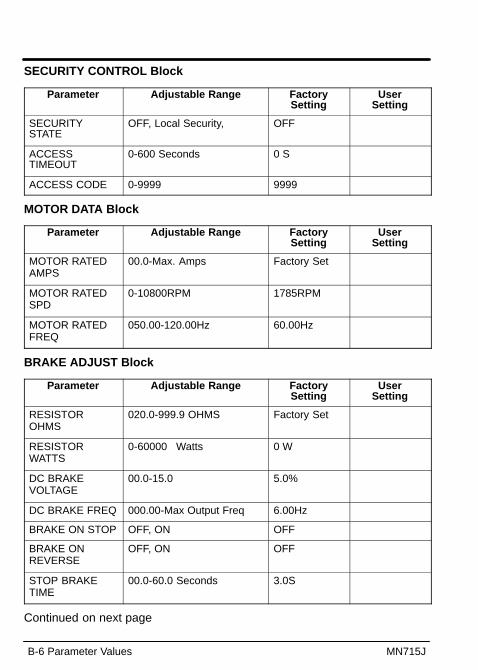
B-6 Parameter Values MN715J
SECURITY CONTROL Block
Parameter Adjustable Range FactorySetting
UserSetting
SECURITYSTATE
OFF, Local Security, OFF
ACCESSTIMEOUT
0-600 Seconds 0 S
ACCESS CODE 0-9999 9999
MOTOR DATA Block
Parameter Adjustable Range FactorySetting
UserSetting
MOTOR RATEDAMPS
00.0-Max. Amps Factory Set
MOTOR RATEDSPD
0-10800RPM 1785RPM
MOTOR RATEDFREQ
050.00-120.00Hz 60.00Hz
BRAKE ADJUST Block
Parameter Adjustable Range FactorySetting
UserSetting
RESISTOROHMS
020.0-999.9 OHMS Factory Set
RESISTORWATTS
0-60000 Watts 0 W
DC BRAKEVOLTAGE
00.0-15.0 5.0%
DC BRAKE FREQ 000.00-Max Output Freq 6.00Hz
BRAKE ON STOP OFF, ON OFF
BRAKE ONREVERSE
OFF, ON OFF
STOP BRAKETIME
00.0-60.0 Seconds 3.0S
Continued on next page
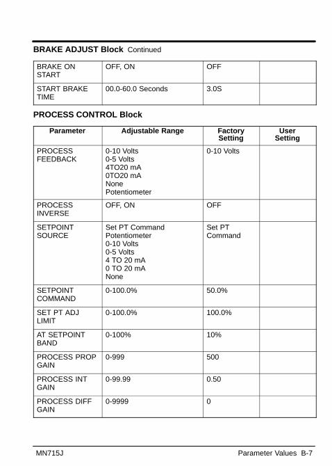
MN715J Parameter Values B-7
BRAKE ADJUST Block Continued
BRAKE ONSTART
OFF, ON OFF
START BRAKETIME
00.0-60.0 Seconds 3.0S
PROCESS CONTROL Block
Parameter Adjustable Range FactorySetting
UserSetting
PROCESSFEEDBACK
0-10 Volts0-5 Volts4TO20 mA0TO20 mANonePotentiometer
0-10 Volts
PROCESSINVERSE
OFF, ON OFF
SETPOINTSOURCE
Set PT CommandPotentiometer0-10 Volts0-5 Volts4 TO 20 mA0 TO 20 mANone
Set PTCommand
SETPOINTCOMMAND
0-100.0% 50.0%
SET PT ADJLIMIT
0-100.0% 100.0%
AT SETPOINTBAND
0-100% 10%
PROCESS PROPGAIN
0-999 500
PROCESS INTGAIN
0-99.99 0.50
PROCESS DIFFGAIN
0-9999 0

B-8 Parameter Values MN715J
SKIP FREQUENCY Block
Parameter Adjustable Range FactorySetting
UserSetting
SKIP FREQ #1 0–Max Output Freq 0.00Hz
SKIP BAND #1 0–50.00Hz 0.00Hz
SKIP FREQ #2 0–Max Output Freq 0.00Hz
SKIP BAND #2 0–50.00Hz 0.00Hz
SKIP FREQ #3 0–Max Output Freq 0.00Hz
SKIP BAND #3 0–50.00Hz 0.00Hz
SYNCHRO STARTS Block
Parameter Adjustable Range FactorySetting
UserSetting
Sync Start FWD OFF, ON OFF
Sync Start REV OFF, ON OFF
Sync at MaxFreq
OFF, ON OFF
Sync Scan V/F 5.0-100.0% 10.0%
Sync SetupTime
0.2-2.0 Seconds 0.2S
Sync Scan Time 01.0-10.0 Seconds 2.0S
Sync V/FRecover
0.2-2.0 Seconds 0.2S

Appendix CRemote Keypad Mounting Template
MN715J Remote Keypad Mounting Template C-1
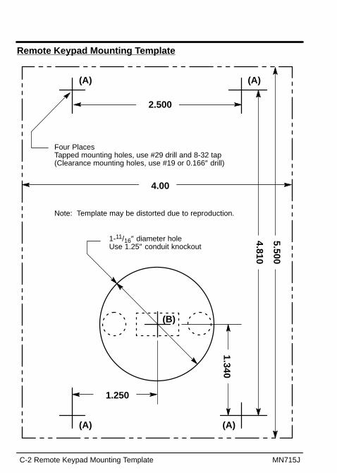
C-2 Remote Keypad Mounting Template MN715J
Remote Keypad Mounting Template
Four PlacesTapped mounting holes, use #29 drill and 8-32 tap(Clearance mounting holes, use #19 or 0.166″ drill)
4.00
2.500
1.250
1.340
4.810
5.500
1-11/16″ diameter holeUse 1.25″ conduit knockout
(B)
(A) (A)
(A) (A)
Note: Template may be distorted due to reproduction.

BALDOR ELECTRIC COMPANYP.O. Box 2400
Fort Smith, AR 72902–2400(501) 646–4711
Fax (501) 648–5792
Baldor Electric Company Printed in USAMN715J 7/99 C&J2500

MN
71
5J
Se
rie
s 1
5J
In
ve
rte
r C
on
tro
l