Series 150 - swtwater.com · 3.2 Installing the Tank Adapter and Valve-Top Mount 8 ... Enclosure...
60
Commercial/Industrial Control System Installation, Operation and Maintenance Manual Series 150
-
Upload
duongtuong -
Category
Documents
-
view
213 -
download
0
Transcript of Series 150 - swtwater.com · 3.2 Installing the Tank Adapter and Valve-Top Mount 8 ... Enclosure...
Commercial/Industrial Control SystemInstallation, Operation and Maintenance Manual
Series 150

This page intentionally blank.
i
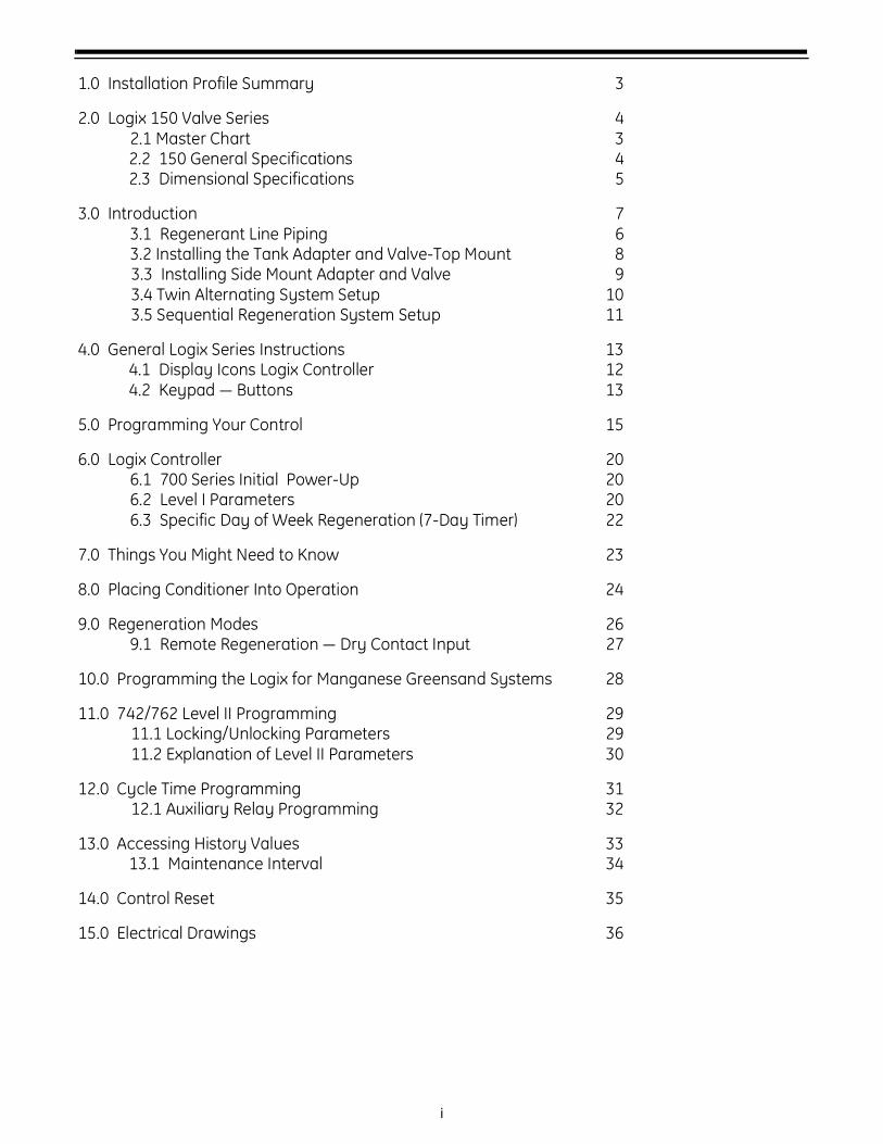
1.0 Installation Profile Summary 3
2.0 Logix 150 Valve Series 42.1 Master Chart 32.2 150 General Specifications 42.3 Dimensional Specifications 5
3.0 Introduction 73.1 Regenerant Line Piping 63.2 Installing the Tank Adapter and Valve-Top Mount 83.3 Installing Side Mount Adapter and Valve 93.4 Twin Alternating System Setup 103.5 Sequential Regeneration System Setup 11
4.0 General Logix Series Instructions 134.1 Display Icons Logix Controller 124.2 Keypad — Buttons 13
5.0 Programming Your Control 15
6.0 Logix Controller 206.1 700 Series Initial Power-Up 206.2 Level I Parameters 206.3 Specific Day of Week Regeneration (7-Day Timer) 22
7.0 Things You Might Need to Know 23
8.0 Placing Conditioner Into Operation 24
9.0 Regeneration Modes 269.1 Remote Regeneration — Dry Contact Input 27
10.0 Programming the Logix for Manganese Greensand Systems 28
11.0 742/762 Level II Programming 2911.1 Locking/Unlocking Parameters 2911.2 Explanation of Level II Parameters 30
12.0 Cycle Time Programming 3112.1 Auxiliary Relay Programming 32
13.0 Accessing History Values 3313.1 Maintenance Interval 34
14.0 Control Reset 35
15.0 Electrical Drawings 36
ii
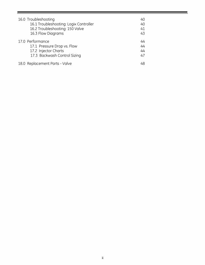
16.0 Troubleshooting 4016.1 Troubleshooting: Logix Controller 4016.2 Troubleshooting: 150 Valve 4116.3 Flow Diagrams 43
17.0 Performance 4417.1 Pressure Drop vs. Flow 4417.2 Injector Charts 4417.3 Backwash Control Sizing 47
18.0 Replacement Parts - Valve 48
1
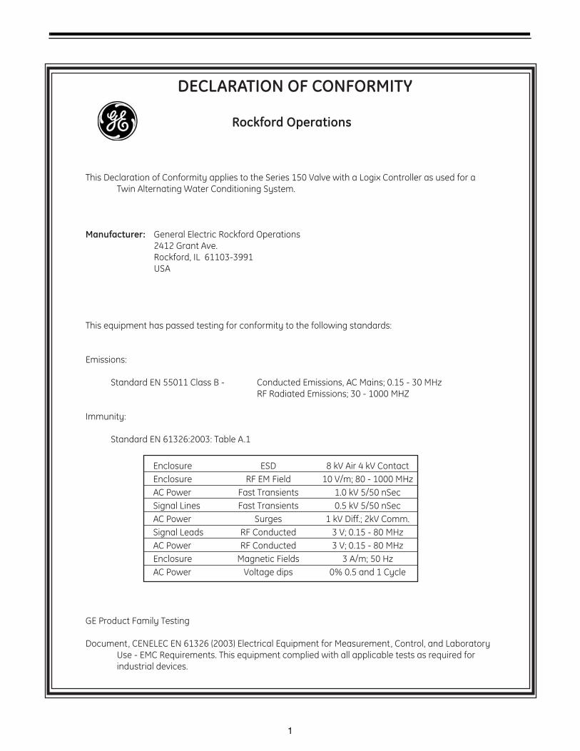
DECLARATION OF CONFORMITY
Rockford Operations
This Declaration of Conformity applies to the Series 150 Valve with a Logix Controller as used for a Twin Alternating Water Conditioning System.
Manufacturer: General Electric Rockford Operations 2412 Grant Ave. Rockford, IL 61103-3991 USA
This equipment has passed testing for conformity to the following standards:
Emissions:
Standard EN 55011 Class B - Conducted Emissions, AC Mains; 0.15 - 30 MHz RF Radiated Emissions; 30 - 1000 MHZ
Immunity:
Standard EN 61326:2003: Table A.1
Enclosure ESD 8 kV Air 4 kV Contact
Enclosure RF EM Field 10 V/m; 80 - 1000 MHz
AC Power Fast Transients 1.0 kV 5/50 nSec
Signal Lines Fast Transients 0.5 kV 5/50 nSec
AC Power Surges 1 kV Diff.; 2kV Comm.
Signal Leads RF Conducted 3 V; 0.15 - 80 MHz
AC Power RF Conducted 3 V; 0.15 - 80 MHz
Enclosure Magnetic Fields 3 A/m; 50 Hz
AC Power Voltage dips 0% 0.5 and 1 Cycle
GE Product Family Testing
Document, CENELEC EN 61326 (2003) Electrical Equipment for Measurement, Control, and Laboratory Use - EMC Requirements. This equipment complied with all applicable tests as required for industrial devices.
2
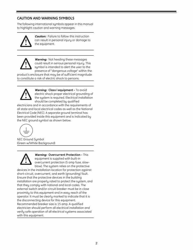
CAUTION AND WARNING SYMBOLSThe following international symbols appear in this manual to highlight caution and warning messages.
Caution: Failure to follow this instruction can result in personal injury or damage to the equipment .
Warning: Not heeding these messages could result in serious personal injury. This symbol is intended to alert the user to the presence of "dangerous voltage" within the
product’s enclosure that may be of sufficient magnitude to constitute a risk of electric shock to persons.
Warning: Class I equipment - To avoid electric shock proper electrical grounding of the system is required. Electrical installation should be completed by qualified
electricians and in accordance with the requirements of all state and local electrical codes as well as the National Electrical Code (NEC). A separate ground terminal has been provided inside this equipment and is indicated by the NEC ground symbol as shown below.
NEC Ground Symbol(Green w/White Background)
Warning: Overcurrent Protection - This equipment is supplied with built-in overcurrent protection (5 amp fuse, slow-blow). The system relies on the protective
devices in the installation location for protection against short-circuit, overcurrent, and earth (grounding) fault. Ensure that the protective devices in the building installation are properly rated to protect the system, and that they comply with national and local codes. The external switch and/or circuit breaker must be in close proximity to this equipment and in easy reach of the operator. It must be clearly marked to indicate that it is the disconnecting device for this equipment. Recommended breaker size is 15 amp. A qualified electrician should perform all electrical installation and verify safe operation of all electrical systems associated with this equipment.

3
1.0 Installation Profile SummaryInstallation Date: _______________________________
Installation Company: ___________________________
Installer(s): _____________________________________
Installer(s) Phone Number:________________________
Application Type: (Softener) (Filter) (Dealkalizer)
Water Source:
(Public Well) (Private Well) (City)
(Surface Supply)
(Other)
Water Test Results:
Hardness: _______________ Iron: _______________
Total Alkalinity: ___________
pH: _____________________
H2S: ____________________
Manganese: _____________
TDS: ____________________
Other: ________________________________________
Misc:
Flow Rates: __________ min. ____________ max.
Tank Size: Diameter _________ Height: ___________
Resin or Media Volume: __________________________
Resin or Media Type: ____________________________
Brine Tank Size: _________________________________
Control Valve Configuration:
Valve Model:
_________ 150 Single Conditioner
_________ 2150 Twin Alternating Conditioner
_________ 153 Single Filter
_________ 2153 Twin Alternating Filter
_________ Sequential Regeneration
(Hard Water Bypass) (No Hard Water Bypass)
Injector: (150-R) (150-A) (150-B) (150-C) (150-D) (Plugged)
Backwash Control: __________________________ gpm
External Refill Control________________________ gpm
Electronic Demand Settings
P1 Time of day ________________
P2 Day of week ________________
P3 Time of regeneration ________________
P4 Number of days between regeneration (99 day calendar override) ________________
P5 Day of week regeneration ________________
Regeneration Frequency:
S M T W T F S
P6 Amount of regenerant used for filter backwash time (salt setting) ________________
P7 System capacity ________________
P8 Hardness ________________
P9 Units of measure ________________
P10 Clock mode ________________
P11 Service interval ________________
P12 Remote regeneration switch delay ____________
P14 Refill rate (conditioner only) ________________
P15 Draw rate (conditioner only) ________________
P16 Reserve type ________________
P17 Initial average or fixed reserve _______________
P18 Flow sensor select ________________
P19 K-factor or pulse equivalent ________________

4
2.0 Logix 150 Valve Series2.1 Master Chart
N T15 42S - A 10B - E S N D
THREAD STYLEN NPT ThreadsB BSPT Threads
VALVE TYPET15 150 Top MountS15 150 Side Mount
CONTROL TYPE (With 2 AUXILIARY RELAY OUTPUTS)*Standard Logix controllers are supplied with TWO fully programmable auxiliary relay outputs (SPDT)
Timeclock Conditioners42S 742 Electronic Timeclock Control, Conditioner
Demand Conditioners62S Conditioner, 762 Demand Control, (NO Turbine Meter or Cable )
62SA Conditioner, 762 with 1 inch Turbine Meter and 10 Foot / 3 Meter Cable62SB Conditioner, 762 with 2 inch Turbine Meter and 10 Foot / 3 Meter Cable62SC Conditioner, 762 with 2 inch Turbine and 1.5 inch Fittings, 10 Foot / 3 Meter Cable
Timeclock Filters42F Filter, 742 Electronic Timeclock Control
Demand Filters62F Filter, 762 Demand Control, (NO Turbine Meter or Cable )
62FA Filter, 762 with 1 inch Turbine Meter and 10 Foot / 3 Meter Cable62FB Filter, 762 with 2 inch Turbine Meter and 10 Foot / 3 Meter Cable62FC Filter, 762 with 2 inch Turbine and 1.5 inch Fittings, 10 Foot / 3 Meter Cable
Twin AlternatingT Twin Control, Valve Only, BLANK TWIN with 15 Foot / 4.6 Meter Interconnect Cable
(Twin must be paired together, via interconnect cable ( included ), with a single tank unit with LOGIX control)
CONTROL TYPE (Without LCD Overlay)(All Logix controls below are supplied without an overlay. For customer supplied overlays.)
Timeclock Conditioners42SE 742 Electronic Timeclock Control, Conditioner
Demand Conditioners62SE Conditioner, 762 Demand Control, (NO Turbine Meter or Cable )
62SAE Conditioner, 762 with 1 inch Turbine Meter and 10 Foot / 3 Meter Cable62SBE Conditioner, 762 with 2 inch Turbine Meter and 10 Foot / 3 Meter Cable62SCE Conditioner, 762 with 2 inch Turbine and 1.5 inch Fittings, 10 Foot / 3 Meter Cable
Timeclock Filters42FE Filter, 742 Electronic Timeclock Control
Demand Filters62FE Filter, 762 Demand Control, (NO Turbine Meter or Cable )
62FAE Filter, 762 with 1 inch Turbine Meter and 10 Foot / 3 Meter Cable62FBE Filter, 762 with 2 inch Turbine Meter and 10 Foot / 3 Meter Cable62FCE Filter, 762 with 2 inch Turbine and 1.5 inch Fittings, 10 Foot / 3 Meter Cable
INJECTOR SIZER GREEN (0.4 - 1.1 gpm [1.5 - 4.2 lpm] Draw), (0.6 - 1.2 gpm [2.3 - 4.5 lpm] Slow Rinse)A YELLOW (0.4 - 1.3 gpm [1.5 - 4.9 lpm] Draw), (0.7 - 1.4 gpm [2.6 - 5.3 lpm] Slow Rinse)B ORANGE (0.6 - 1.2 gpm [2.3 - 4.5 lpm] Draw), (1.1 - 2.1 gpm [4.2 - 7.9 lpm] Slow Rinse)C GOLD (0.9 - 1.7 gpm [3.4 - 6.4 lpm] Draw), (2.4 - 4.7 gpm [9.1 - 17.8 lpm] Slow Rinse)D BROWN (1.2 - 2.4 gpm [4.5 - 9.1 lpm] Draw), (3.0 - 6.0 gpm [11.4 - 22.7 lpm] Slow Rinse)F Blank Injector (For 3 Cycle Filter)N None
BACKWASH SIZE, (.75 inch) BACKWASH SIZE, (1.5 inch)3 3 gpm [11.3 lpm] 12B 12 gpm [45.4 lpm]4 4 gpm [15.1 lpm] 15B 15 gpm [56.8 lpm]5 5 gpm [18.9 lpm] 20B 20 gpm [75.7 lpm]6 6 gpm [22.7 lpm] 25B 25 gpm [94.6 lpm]7 7 gpm [26.5 lpm] 30B 30 gpm [113.6 lpm]9 9 gpm [34.1 lpm] 35B 35 gpm [132.5 lpm]
10 10 gpm [37.8 lpm] 40B 40 gpm [151.4 lpm]12 12 gpm [45.4 lpm] NB OPEN (No Flow Washer)15 15 gpm [56.8 lpm]25 25 gpm [94.6 lpm]N OPEN (No Flow Washer)
LANGUAGEE EnglishC ChineseJ JapaneseN None
POWER**T 100VAC 50/60Hz 100/115V 50/60Hz Drive*S 115VAC 60Hz 100/115V 50/60Hz Drive
**T2 200VAC 50/60Hz 230V 50/60Hz Drive**H 230VAC 50/60Hz 230V 50/60Hz Drive
*115VAC 60Hz option is supplied with a " North American" (NA) Logix controller and will not operate with 50Hz power. North American Logix controllers will default to ENGLISH units of measure and a 12 hour clock setting.
**All other power configurations are supplied with " World" (WD) Logix controllers that operate with either 50 or 60 Hz power. The World controller senses the electrical input and determines English or Metric units of measure and 12 or 24 hour clock settings. Default settings can be modified on the Logix control.
POWER CORDN North American (115VAC ONLY)C EuropeanJ Japanese (100VAC and 200VAC Only)A AustralianU United Kingdom (Re-Wireable)
DUPLEXD No Shut-off
DC Shut-off with composite valveDS Shut-off with stainless steel valve
5
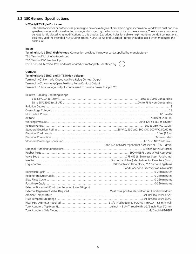
2.2 150 General SpecificationsNEMA 4/IP65 Style Enclosure
Intended for indoor or outdoor use primarily to provide a degree of protection against corrosion, windblown dust and rain, splashing water, and hose-directed water; undamaged by the formation of ice on the enclosure. The enclosure door must be kept tightly closed. Any modifications to this product (i.e. added holes for cable entry/mounting, conduit connections... etc.) may void the intended NEMA4/IP65 rating. NEMA 4/IP65 and UL rated fittings should be used when modifying the enclosure.
Inputs Terminal Strip 1 (TB1) High Voltage (Connection provided via power cord, supplied by manufacturer)TB1, Terminal "L": Line Voltage InputTB2, Terminal "N": Neutral InputEarth Ground, Terminal Post and Nuts located on motor plate. Identified by
Outputs Terminal Strip 2 (TB2) and 3 (TB3) High VoltageTerminal "NC": Normally Closed Auxiliary Relay Contact OutputTerminal "NO": Normally Open Auxiliary Relay Contact OutputTerminal "L": Line Voltage Output (can be used to provide power to input "C").
Relative Humidity Operating Range1 to 65°C (34 to 150°F) . . . . . . . . . . . . . . . . . . . . . . . . . . . . . . . . . . . . . . . . . . . . . . . . . . . . . . . . . . . . . . . . . .10% to 100% Condensing38 to 55°C (100 to 131°F) . . . . . . . . . . . . . . . . . . . . . . . . . . . . . . . . . . . . . . . . . . . . . . . . . . . . . . . . . . . 10% to 75% Non-Condensing
Pollution Degree . . . . . . . . . . . . . . . . . . . . . . . . . . . . . . . . . . . . . . . . . . . . . . . . . . . . . . . . . . . . . . . . . . . . . . . . . . . . . . . . . . . . . . . . . . . . . . . . . . . . .2Overvoltage Category . . . . . . . . . . . . . . . . . . . . . . . . . . . . . . . . . . . . . . . . . . . . . . . . . . . . . . . . . . . . . . . . . . . . . . . . . . . . . . . . . . . . . . . . . . . . . 11Max. Rated Power . . . . . . . . . . . . . . . . . . . . . . . . . . . . . . . . . . . . . . . . . . . . . . . . . . . . . . . . . . . . . . . . . . . . . . . . . . . . . . . . . . . . . . . . . . 125 WattsAltitude . . . . . . . . . . . . . . . . . . . . . . . . . . . . . . . . . . . . . . . . . . . . . . . . . . . . . . . . . . . . . . . . . . . . . . . . . . . . . . . . . . . . . . . . . . . . 6500 feet (2000 m)Working Pressure . . . . . . . . . . . . . . . . . . . . . . . . . . . . . . . . . . . . . . . . . . . . . . . . . . . . . . . . . . . . . . . . . . . . . . . . . . 20 to 125 psi (1.4 to 8.6 bar)Voltage Range. . . . . . . . . . . . . . . . . . . . . . . . . . . . . . . . . . . . . . . . . . . . . . . . . . . . . . . . . . . . . . . . . . . . . . . . . . . . . . . . . . 100 to 230 VAC (±10%)Standard Electrical Rating . . . . . . . . . . . . . . . . . . . . . . . . . . . . . . . . . . . . . . . . . . . . . . . . 115 VAC, 230 VAC, 100 VAC, 200 VAC, 50/60 HzElectrical Cord Length. . . . . . . . . . . . . . . . . . . . . . . . . . . . . . . . . . . . . . . . . . . . . . . . . . . . . . . . . . . . . . . . . . . . . . . . . . . . . . . . . . . . 6 feet (1.8 m)Electrical Connection . . . . . . . . . . . . . . . . . . . . . . . . . . . . . . . . . . . . . . . . . . . . . . . . . . . . . . . . . . . . . . . . . . . . . . . . . . . . . . . . . . . .Terminal stripStandard Plumbing Connections . . . . . . . . . . . . . . . . . . . . . . . . . . . . . . . . . . . . . . . . . . . . . . . . . . . . . . . . . . . . . . . 1-1/2 in NPT/BSPT inlet and 1/2 inch NPT regenerant / 3/4 inch NPT/BSPT drain Optional Plumbing Connections . . . . . . . . . . . . . . . . . . . . . . . . . . . . . . . . . . . . . . . . . . . . . . . . . . . . . . . . . . . . . 1-1/2 inch NPT/BSPT drain Rubber Parts . . . . . . . . . . . . . . . . . . . . . . . . . . . . . . . . . . . . . . . . . . . . . . . . . . . . . . . . . . . . . . . . . . . . . . . EPDM (NSF61 and WRAS Approved)Valve Body . . . . . . . . . . . . . . . . . . . . . . . . . . . . . . . . . . . . . . . . . . . . . . . . . . . . . . . . . . . . . . . . . . . . . .CF8M (316) Stainless Steel (Passivated)Injector. . . . . . . . . . . . . . . . . . . . . . . . . . . . . . . . . . . . . . . . . . . . . . . . . . . . . . . . . . . . . . 5 sizes available, (refer to Injector Flow Rate Chart)Logix Control . . . . . . . . . . . . . . . . . . . . . . . . . . . . . . . . . . . . . . . . . . . . . . . . . . . . . . . . . 742 Electronic TIme Clock, 762 Demand Systems
Conditioner and Filter Versions AvailableBackwash Cycle . . . . . . . . . . . . . . . . . . . . . . . . . . . . . . . . . . . . . . . . . . . . . . . . . . . . . . . . . . . . . . . . . . . . . . . . . . . . . . . . . . . . . . . .0-250 minutesRegenerant Draw Cycle . . . . . . . . . . . . . . . . . . . . . . . . . . . . . . . . . . . . . . . . . . . . . . . . . . . . . . . . . . . . . . . . . . . . . . . . . . . . . . . . .0-250 minutesSlow Rinse Cycle. . . . . . . . . . . . . . . . . . . . . . . . . . . . . . . . . . . . . . . . . . . . . . . . . . . . . . . . . . . . . . . . . . . . . . . . . . . . . . . . . . . . . . . .0-250 minutesFast Rinse Cycle . . . . . . . . . . . . . . . . . . . . . . . . . . . . . . . . . . . . . . . . . . . . . . . . . . . . . . . . . . . . . . . . . . . . . . . . . . . . . . . . . . . . . . . .0-250 minutesExternal Backwash Controller Required (over 40 gpm)External Regenerant Valve Required . . . . . . . . . . . . . . . . . . . . . . . . . . . . . . . . .Must have positive shut-off on refill and draw downAmbient Temperature. . . . . . . . . . . . . . . . . . . . . . . . . . . . . . . . . . . . . . . . . . . . . . . . . . . . . . . . . . . . . . . . . . . . . . . . .34°F (1°C) to 150°F (65°C)Fluid Temperature Range . . . . . . . . . . . . . . . . . . . . . . . . . . . . . . . . . . . . . . . . . . . . . . . . . . . . . . . . . . . . . . . . . . . . .34°F (1°C) to 180°F (82°C)Riser Pipe Diameter Required. . . . . . . . . . . . . . . . . . . . . . . . . . . . . . . . . . . . . . .1-1/2 in schedule 40 PVC (42 mm O.D. x 3.8 mm wall)Tank Adapters (Top Mount) . . . . . . . . . . . . . . . . . . . . . . . . . . . . . . . . . . . . . . . . . . . 4 inch - 8 UN Thread with 1-1/2 inch Riser (42mm)Tank Adapters (Side Mount) . . . . . . . . . . . . . . . . . . . . . . . . . . . . . . . . . . . . . . . . . . . . . . . . . . . . . . . . . . . . . . . . . . . . . . . 1-1/2 inch NPT/BSPT
6
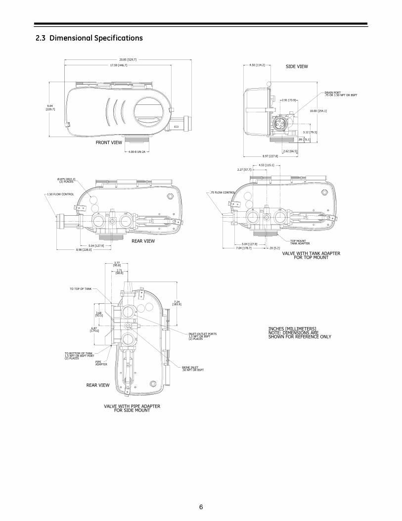
2.3 Dimensional Specifications
20.85 [529.7]
17.59 [446.7]
9.04 [229.7]
4.50 [114.2]
2.91 [73.9]
3.12 [79.3]
.99 [25.1]
2.62 [66.5]
10.00 [254.1]
5.04 [127.9]
7.04 [178.7] .20 [5.2]
4.53 [115.1]
2.27 [57.7]
TOP MOUNTTANK ADAPTER
5.04 [127.9]
8.98 [228.0]
4.00-8 UN-2A
FRONT VIEW
REAR VIEW
DRAIN PORT.75 OR 1.50 NPT OR BSPT
8.97 [227.8]
SIDE VIEW
IN OUT
IN OUT
Ø.875 [Ø22.2](2) PLACES
1.50 FLOW CONTROL.75 FLOW CONTROL
VALVE WITH TANK ADAPTERFOR TOP MOUNT
INCHES [MILLIMETERS]NOTE: DIMENSIONS ARESHOWN FOR REFERENCE ONLY
3.68 [93.5]
7.24 [183.9]
2.71[68.8]
3.77 [95.8]
PIPE ADAPTER
TO BOTTOM OF TANK1.5 NPT OR BSPT PORT(2) PLACES
TO TOP OF TANK
BRINE INLET.50 NPT OR BSPT
INLET-OUTLET PORTS1.5 NPT OR BSPT(2) PLACES
INO
UT
REAR VIEW
VALVE WITH PIPE ADAPTERFOR SIDE MOUNT
6.87 [174.6]
7
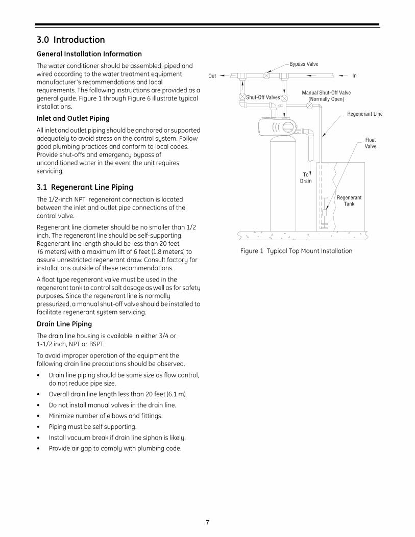
3.0 IntroductionGeneral Installation Information
The water conditioner should be assembled, piped and wired according to the water treatment equipment manufacturer’s recommendations and local requirements. The following instructions are provided as a general guide. Figure 1 through Figure 6 illustrate typical installations.
Inlet and Outlet Piping
All inlet and outlet piping should be anchored or supported adequately to avoid stress on the control system. Follow good plumbing practices and conform to local codes. Provide shut-offs and emergency bypass of unconditioned water in the event the unit requires servicing.
3.1 Regenerant Line PipingThe 1/2-inch NPT regenerant connection is located between the inlet and outlet pipe connections of the control valve.
Regenerant line diameter should be no smaller than 1/2 inch. The regenerant line should be self-supporting. Regenerant line length should be less than 20 feet (6 meters) with a maximum lift of 6 feet (1.8 meters) to assure unrestricted regenerant draw. Consult factory for installations outside of these recommendations.
A float type regenerant valve must be used in the regenerant tank to control salt dosage as well as for safety purposes. Since the regenerant line is normally pressurized, a manual shut-off valve should be installed to facilitate regenerant system servicing.
Drain Line Piping
The drain line housing is available in either 3/4 or 1-1/2 inch, NPT or BSPT.
To avoid improper operation of the equipment the following drain line precautions should be observed.
• Drain line piping should be same size as flow control, do not reduce pipe size.
• Overall drain line length less than 20 feet (6.1 m).
• Do not install manual valves in the drain line.
• Minimize number of elbows and fittings.
• Piping must be self supporting.
• Install vacuum break if drain line siphon is likely.
• Provide air gap to comply with plumbing code.
Figure 1 Typical Top Mount Installation
Float Valve
Regenerant Line
Manual Shut-Off Valve(Normally Open)
In
Bypass Valve
Shut-Off Valves
Out
ToDrain
RegenerantTank
8
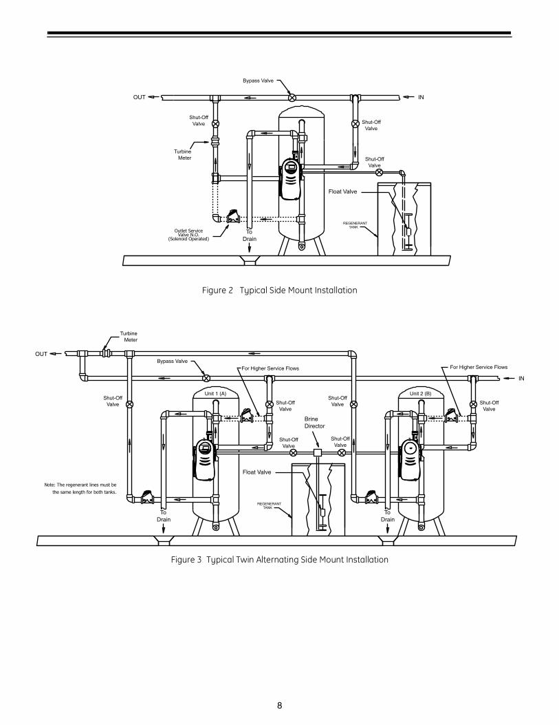
Figure 2 Typical Side Mount Installation
Figure 3 Typical Twin Alternating Side Mount Installation
Shut-Off
Valve
OUT
To
Drain
Shut-Off
Valve
Bypass Valve
IN
Turbine
Meter
REGENERANTTANK
Float Valve
Su Tu We Th Fr SaMo
Time/Day
CapacityHardness
Regeneration Time/Day
In Service
Salt Amount
Days
Shut-Off
Valve
Outlet ServiceValve N.O.
(Solenoid Operated)
Shut-Off
Valve
OUT
To
Drain
Shut-Off
Valve
Bypass Valve
Shut-Off
Valve
IN
To
Drain
Shut-Off
Valve
Turbine
Meter
REGENERANTTANK
Float Valve
Su Tu We Th Fr SaMo
Time/Day
CapacityHardness
Regeneration Time/Day
In Service
Salt Amount
Days
Unit 2 (B)Unit 1 (A)
Brine
Director
Shut-Off
ValveShut-Off
Valve
For Higher Service Flows For Higher Service Flows
Note: The regenerant lines must be
the same length for both tanks.
9
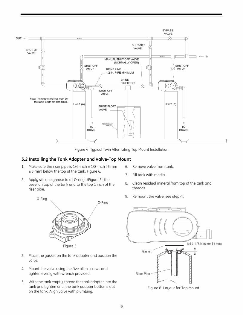
Figure 4 Typical Twin Alternating Top Mount Installation
3.2 Installing the Tank Adapter and Valve-Top Mount1. Make sure the riser pipe is 1/4-inch ± 1/8-inch ( 6 mm
± 3 mm) below the top of the tank, Figure 6.
2. Apply silicone grease to all O-rings (Figure 5), the bevel on top of the tank and to the top 1 inch of the riser pipe.
Figure 5
3. Place the gasket on the tank adapter and position the valve.
4. Mount the valve using the five allen screws and tighten evenly with wrench provided.
5. With the tank empty, thread the tank adapter into the tank and tighten until the tank adapter bottoms out on the tank. Align valve with plumbing.
6. Remove valve from tank.
7. Fill tank with media.
8. Clean residual mineral from top of the tank and threads.
9. Remount the valve (see step 4).
Figure 6 Layout for Top Mount
DRAIN
TO
SHUT-OFF
VALVE
BRINE FLOAT
VALVE
SHUT-OFF
VALVE
INMANUAL SHUT-OFF VALVE
(NORMALLY OPEN)
BRINE LINE
1/2 IN. PIPE MINIMUM
OUT
Su Tu We Th Fr SaMo
Time/Day
CapacityHardness
Regeneration Time/Day
In Service
Salt Amount
Days
BYPASS
VALVE
SHUT-OFF
VALVE
SHUT-OFF
VALVE
Unit 1 (A) Unit 2 (B)
DRAIN
TO
REGENERANTTANK
SHUT-OFF
VALVE
BRINE
DIRECTOR
Note: The regenerant lines must be
the same length for both tanks.
O-RingO-Ring
1/4 1/8 in
Riser Pipe
Gasket
(6 mm 3 mm)+- +-
10
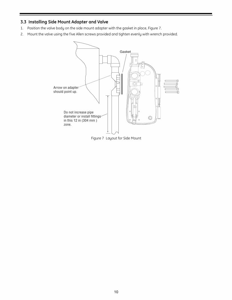
3.3 Installing Side Mount Adapter and Valve1. Position the valve body on the side mount adapter with the gasket in place, Figure 7.
2. Mount the valve using the five Allen screws provided and tighten evenly with wrench provided.
Figure 7 Layout for Side Mount
Gasket
INO
UT
Do not increase pipe diameter or install fittings in this 12 in (304 mm ) zone.
Arrow on adapter should point up.
11
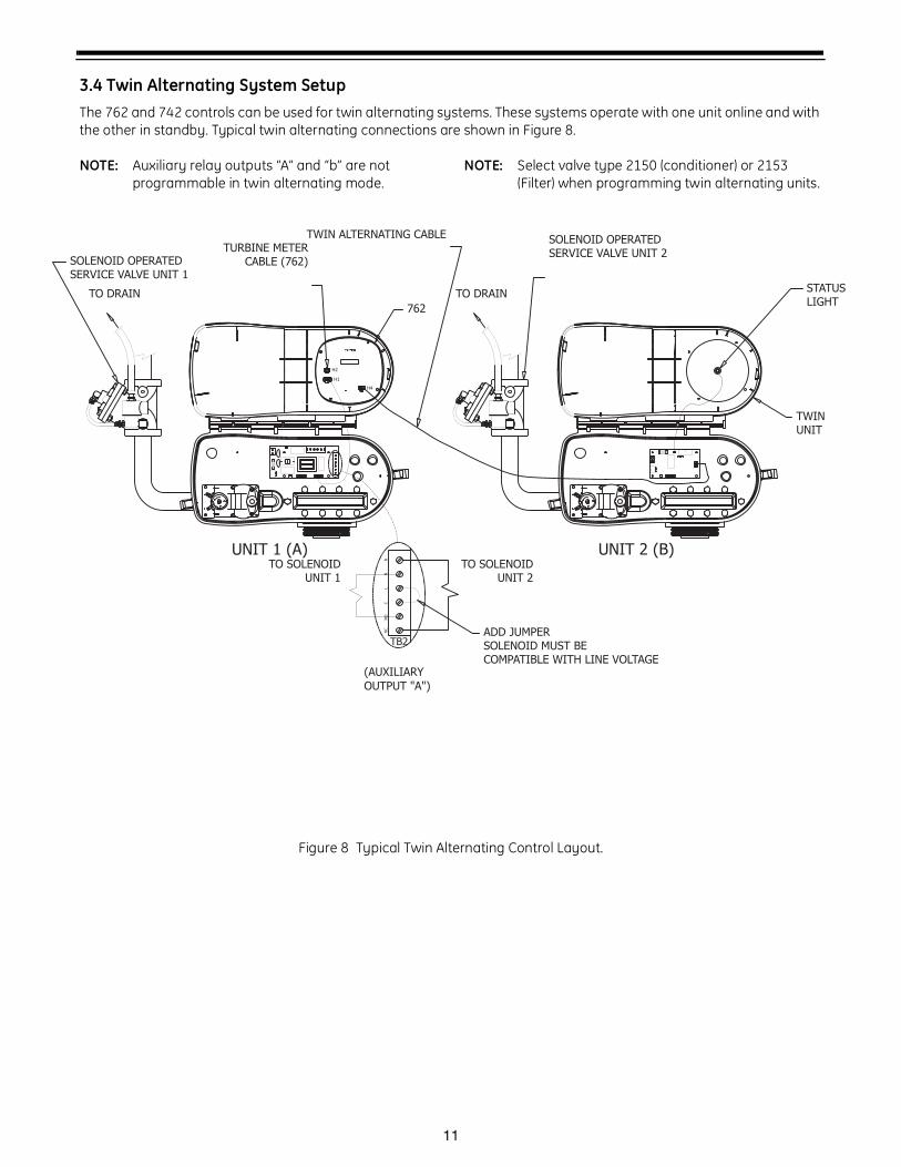
3.4 Twin Alternating System SetupThe 762 and 742 controls can be used for twin alternating systems. These systems operate with one unit online and with the other in standby. Typical twin alternating connections are shown in Figure 8.
NOTE: Auxiliary relay outputs “A” and “b” are not programmable in twin alternating mode.
NOTE: Select valve type 2150 (conditioner) or 2153 (Filter) when programming twin alternating units.
Figure 8 Typical Twin Alternating Control Layout.
5 AMP SLO-BLOW
NL
LN
5 A
MP S
LO
-BLO
W
NC
NO
CL
NN
NCNOCLNN
NC
NO
CL
NN
LBL1
230V
115V
MO
V1
MO
V2
TWINUNIT
762
ADD JUMPERSOLENOID MUST BECOMPATIBLE WITH LINE VOLTAGE
SOLENOID OPERATEDSERVICE VALVE UNIT 1
TWIN ALTERNATING CABLE SOLENOID OPERATEDSERVICE VALVE UNIT 2
H2
H1
H4
TURBINE METERCABLE (762)
(AUXILIARY
OUTPUT "A")
STATUSLIGHT
TO DRAIN
TO SOLENOIDUNIT 1
UNIT 1 (A) UNIT 2 (B)TO SOLENOID
UNIT 2
TO DRAIN
TB2
12
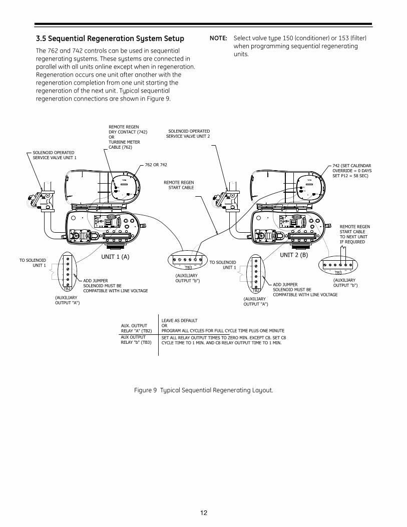
3.5 Sequential Regeneration System SetupThe 762 and 742 controls can be used in sequential regenerating systems. These systems are connected in parallel with all units online except when in regeneration. Regeneration occurs one unit after another with the regeneration completion from one unit starting the regeneration of the next unit . Typical sequential regeneration connections are shown in Figure 9.
NOTE: Select valve type 150 (conditioner) or 153 (filter) when programming sequential regenerating units.
Figure 9 Typical Sequential Regenerating Layout.
NCNOCLNN
LN
5 A
MP S
LO
-BLO
W
NC
NO
CL
NN
NCNOCLNN
NC
NO
CL
NN
NC
NO
CL
NN
NCNOCLNN
LN
5 A
MP S
LO
-BLO
W
NC
NO
CL
NN
NCNOCLNN
230V
115V
MO
V1
MO
V2
762 OR 742
ADD JUMPERSOLENOID MUST BECOMPATIBLE WITH LINE VOLTAGE
AUX. OUTPUT
RELAY "A" (TB2)
AUX OUTPUT
RELAY "b" (TB3)
LEAVE AS DEFAULTORPROGRAM ALL CYCLES FOR FULL CYCLE TIME PLUS ONE MINUTE
SET ALL RELAY OUTPUT TIMES TO ZERO MIN. EXCEPT C8. SET C8 CYCLE TIME TO 1 MIN. AND C8 RELAY OUTPUT TIME TO 1 MIN.
SOLENOID OPERATEDSERVICE VALVE UNIT 1
SOLENOID OPERATEDSERVICE VALVE UNIT 2
ADD JUMPERSOLENOID MUST BECOMPATIBLE WITH LINE VOLTAGE
230V
115V
MO
V1
MO
V2
H2
H1
H4
H2
H1
H4
REMOTE REGENDRY CONTACT (742)ORTURBINE METERCABLE (762)
742 (SET CALENDAROVERRIDE = 0 DAYSSET P12 = 58 SEC)
(AUXILIARY
OUTPUT "b")
(AUXILIARY
OUTPUT "A")
(AUXILIARY
OUTPUT "b")
(AUXILIARY
OUTPUT "A")
TO SOLENOIDUNIT 1
UNIT 1 (A) UNIT 2 (B)TO SOLENOID
UNIT 1
REMOTE REGENSTART CABLE
REMOTE REGENSTART CABLETO NEXT UNITIF REQUIRED
TB2TB2
TB3
TB3
13
4.0 General Logix Series Instructions
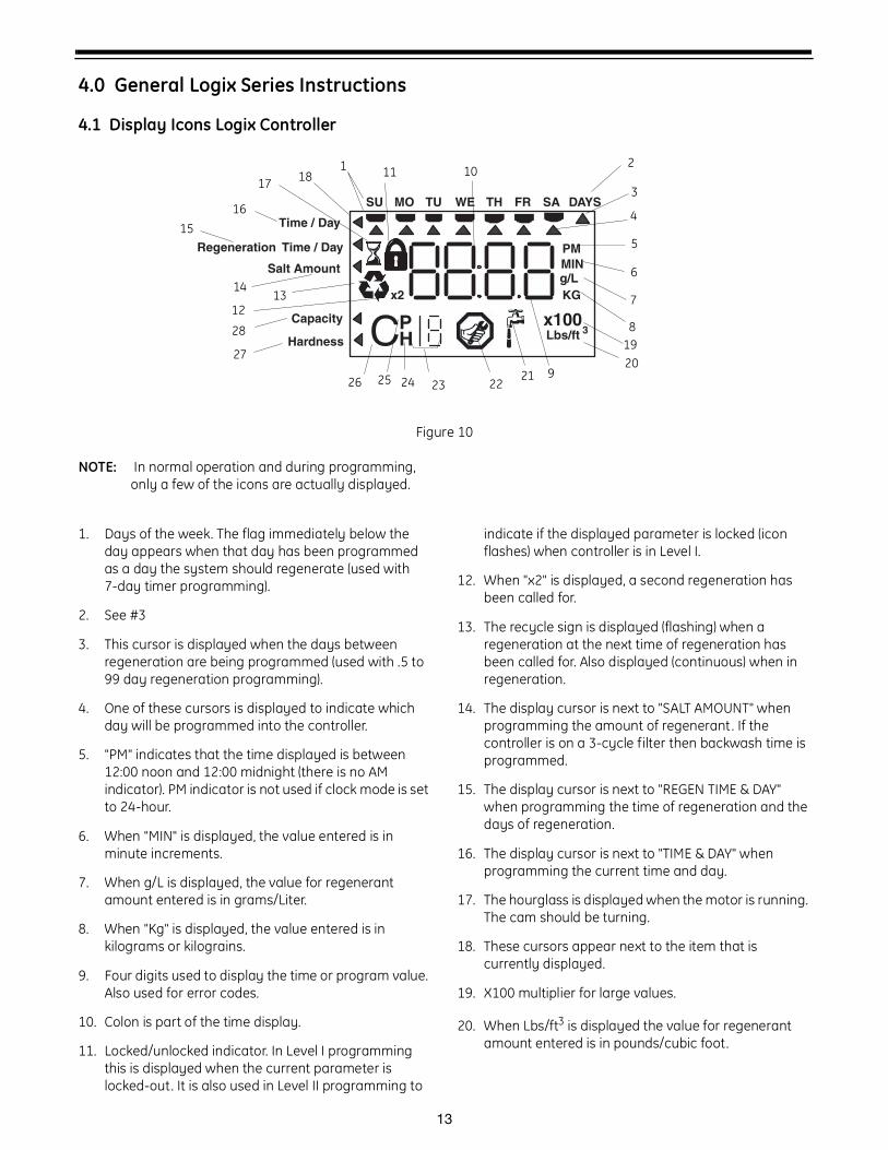
4.1 Display Icons Logix Controller
Figure 10
NOTE: In normal operation and during programming, only a few of the icons are actually displayed.
1. Days of the week. The flag immediately below the day appears when that day has been programmed as a day the system should regenerate (used with 7-day timer programming).
2. See #3
3. This cursor is displayed when the days between regeneration are being programmed (used with .5 to 99 day regeneration programming).
4. One of these cursors is displayed to indicate which day will be programmed into the controller.
5. "PM" indicates that the time displayed is between 12:00 noon and 12:00 midnight (there is no AM indicator). PM indicator is not used if clock mode is set to 24-hour.
6. When "MIN" is displayed, the value entered is in minute increments.
7. When g/L is displayed, the value for regenerant amount entered is in grams/Liter.
8. When "Kg" is displayed, the value entered is in kilograms or kilograins.
9. Four digits used to display the time or program value. Also used for error codes.
10. Colon is part of the time display.
11. Locked/unlocked indicator. In Level I programming this is displayed when the current parameter is locked-out. It is also used in Level II programming to
indicate if the displayed parameter is locked (icon flashes) when controller is in Level I.
12. When "x2" is displayed, a second regeneration has been called for.
13. The recycle sign is displayed (flashing) when a regeneration at the next time of regeneration has been called for. Also displayed (continuous) when in regeneration.
14. The display cursor is next to "SALT AMOUNT" when programming the amount of regenerant . If the controller is on a 3-cycle filter then backwash time is programmed.
15. The display cursor is next to "REGEN TIME & DAY" when programming the time of regeneration and the days of regeneration.
16. The display cursor is next to "TIME & DAY" when programming the current time and day.
17. The hourglass is displayed when the motor is running. The cam should be turning.
18. These cursors appear next to the item that is currently displayed.
19. X100 multiplier for large values.
20. When Lbs/ft3 is displayed the value for regenerant amount entered is in pounds/cubic foot.
g/L
PMMIN
KGx2
Time / Day
Regeneration Time / Day
Salt Amount
SU MO TU WE TH FR SA DAYS
PHCCapacity
Hardness
x100Lbs/ft 3
1 2
3
4
5
6
7
8
9
1011
1213
14
1516
17 18
1920
212223242526
27
28
14
21. Faucet is displayed when the current flow rate is displayed. Control may show the faucet and "0", indicating no flow.
22. Maintenance interval display turns on if the months in service exceed the value programmed in P17.
23. Used with #24, #25, and #26. Displays a sequence number or a value.
24. History Values (H). The number displayed by #23 identifies which history value is currently displayed.
25. Parameter (P). Displayed only in Level II Programming. The number displayed by #23 identifies which parameter is currently displayed.
26. Cycle (C). The number displayed by #23 is the current cycle in the regeneration sequence.
27. Hardness setting—only used with 762 controllers.
28. Capacity display—shows estimated system capacity.
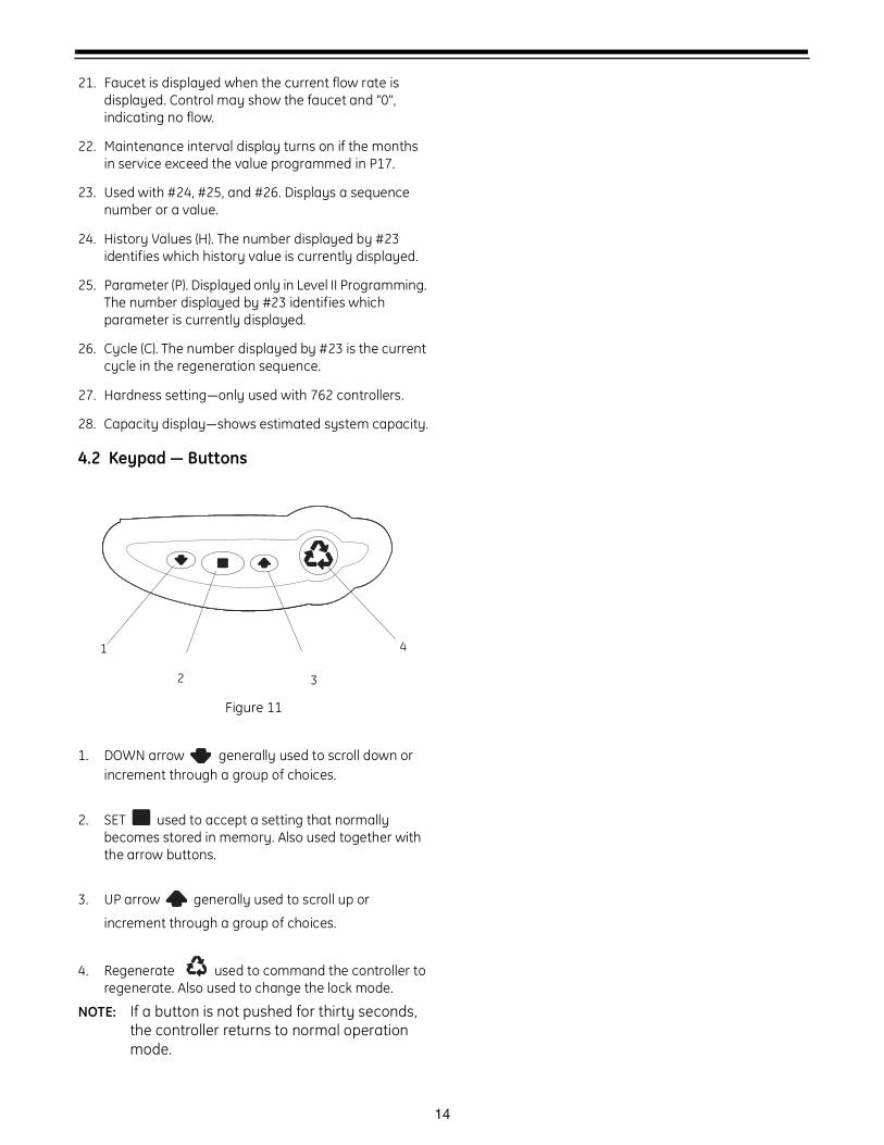
4.2 Keypad — Buttons
Figure 11
1. DOWN arrow generally used to scroll down or increment through a group of choices.
2. SET used to accept a setting that normally becomes stored in memory. Also used together with the arrow buttons.
3. UP arrow generally used to scroll up or
increment through a group of choices.
4. Regenerate used to command the controller to regenerate. Also used to change the lock mode.
NOTE: If a button is not pushed for thirty seconds, the controller returns to normal operation mode.
2
1
3
4
15
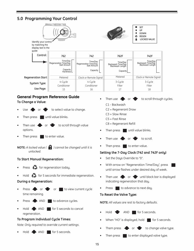
5.0 Programming Your Control
General Program Reference GuideTo Change a Value:
• Use or to select value to change.
• Then press until value blinks.
• Then use or to scroll through value options.
• Then press to enter value.
NOTE: A locked value ( ) cannot be changed until it is unlocked.
To Start Manual Regeneration:
• Press for regeneration today.
• Hold for 5 seconds for immediate regeneration.
During a Regeneration:
• Press or or to view current cycle
time remaining.
• Press AND to advance cycles.
• Hold AND for 5 seconds to cancel
regeneration.
To Program Individual Cycle Times:
Note: Only required to override current settings.
• Hold AND for 5 seconds.
• Then use or to scroll through cycles.
C1 - BackwashC2 = Regenerant DrawC3 = Slow RinseC5 = Fast RinseC8 = Regenerant Refill
• Then press until value blinks.
• Then use or to scroll.
• Then press to enter value.
Setting the 7-Day Clock (742 and 742F only)
• Set the Days Override to "0".
• With arrow on “Regeneration Time/Day”, press
until arrow flashes under desired day of week.
• Then use or until black bar is displayed indicating regeneration that day.
• Press to advance to next day.
To Reset the Valve Type:
NOTE: All values are rest to factory defaults.
• Hold AND for 5 seconds.
• When “HO” is displayed, hold for 5 seconds.
• Them press or to change valve type.
• Then press to enter displayed valve type.
SET
UP
DOWN
REGEN
LOCKED VALUE
Time & Day
Regen Time & Day
Salt
SU MO TU WE TH FR SA DAYS
LBS
PMMIN
KG
x100x2
PHC
Capacity
Hardness
Control:
System Type:
Use Page:
762
Time/DayRegeneration Time/Day
Salt Amount
CapacityHardness
4-Cycle
Conditioner
15
742
Time/DayRegeneration Time/Day
Salt Amount
Capacity
4-Cycle
Conditioner
16
762F
Time/Day
Capacity
Backwash Time/DayBackwash Length
3-Cycle
Filter
17
742F
Time/DayBackwash Time/Day
Backwash Length
3-Cycle
Filter
18
Regeneration Start Metered Clock or Remote Signal Metered Clock or Remote Signal
Identify your control by matching the display text to the guide
16
Grains/gal: 3 to 200
SU MO TU WE TH FR SA DAYS
SU MO TU WE TH FR SA DAYS
SU MO TU WE TH FR SA DAYS
SU MO TU WE TH FR SA DAYS
SU MO TU WE TH FR SA DAYS
SU MO TU WE TH FR SA DAYS
SU MO TU WE TH FR SA DAYS
Lbs/ft3
SU MO TU WE TH FR SA DAYS
KG
Time/Day
Salt Amount
SU MO TU WE TH FR SA DAYS
Capacity
Hardness
Time/Day
Regeneration Time/Day
Salt Amount
SU MO TU WE TH FR SA DAYS
Capacity
Hardness
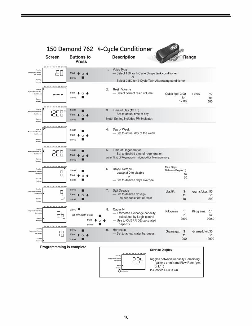
1. Valve Type ⎯ Select 150 for 4-Cycle Single tank conditioner or ⎯ Select 2150 for 4-Cycle Twin-Alternating conditioner
2. Resin Volume ⎯ Select correct resin volume Cubic feet: 3.00
to 17.00
3. Time of Day (12 hr.) ⎯ Set to actual time of day
Note: Setting includes PM indicator.
4. Day of Week ⎯ Set to actual day of the week
5. Time of Regeneration ⎯ Set to desired time of regenerationNote: Time of Regeneration is ignored for Twin-alternating.
6. Days Override ⎯ Leave at 0 to disable or ⎯ Set to desired days override
7. Salt Dosage ⎯ Set to desired dosage lbs per cubic feet of resin
8. Capacity ⎯ Estimated exchange capacity calculated by Logix control ⎯ Use to OVERRIDE calculated capacity
9. Hardness ⎯ Set to actual water hardness
Screen Buttons to Description Range Press
0 to 99
Lbs/ft3: 3 to 18
Kilograins: 1 to 9999
Programmming is complete
orpress
then
orpress
then
or
press
press
then
or
press
press
then
or
press
press
then
or
press
press
then
or
press
press
then
or
press
press
then
press
or
press
press
then
to override
Service Display
Toggles between Capacity Remaining (gallons or m ) and Flow Rate (g/m or L/m)
150 Demand 762 4-Cycle Conditioner
PM
Max. Days Between Regen:
In Service LED is OnIn Service
3
Grams/Liter: 30 to 2000
grams/Liter: 50 to 290
Kilograms: 0.1 to 999.9
Liters: 75 to 500
Time/Day
Salt Amount
Capacity
Hardness
Time/Day
Salt Amount
Capacity
Hardness
Time/Day
Salt Amount
Capacity
Hardness
Time/Day
Salt Amount
Capacity
Hardness
Time/Day
Salt Amount
Capacity
Hardness
Time/Day
Salt Amount
Capacity
Hardness
Time/Day
Salt Amount
Capacity
Hardness
Time/Day
Salt Amount
Capacity
Hardness
Regeneration Time/Day
Regeneration Time/Day
Regeneration Time/Day
Regeneration Time/Day
Regeneration Time/Day
Regeneration Time/Day
Regeneration Time/Day
Regeneration Time/Day
Regeneration Time/Day

17
SU MO TU WE TH FR SA DAYS
SU MO TU WE TH FR SA DAYS
SU MO TU WE TH FR SA DAYS
SU MO TU WE TH FR SA DAYS
SU MO TU WE TH FR SA DAYS
SU MO TU WE TH FR SA DAYS
SU MO TU WE TH FR SA DAYS
KG
SU MO TU WE TH FR SA DAYS
2. Resin Volume ⎯ Select correct resin volume Cubic feet: 3.00
to 17.00
3. Time of Day (12 hr.) ⎯ Set to actual time of day
Note: Setting includes PM indicator.
4. Day of Week ⎯ Set to actual day of the week
5. Time of Regeneration ⎯ Set to desired time of regeneration
6. Days Between Regeneration ⎯ Set to desired days between regeneration or ⎯ Set at 0 to program as a 7-day
timer
7. Salt Dosage ⎯ Set to desired dosage
8. Estimated Exchange Capacity (view only) ⎯ Based on resin volume and salt setting
Screen Buttons to Description Range Press
Days: 0 to 99
Lbs/ft3: 3 to 18
Programmming is complete
orpress
then
orpress
then
or
press
press
then
or
press
press
then
or
press
press
then
or
press
press
then
or
press
press
then
press
Service Display
Displays actual day of the week and time of day
PM
PM
150 Time Clock 742 4-Cycle Conditioner
1. Valve Type ⎯ Select 150 for 4-Cycle Single tank conditioner or ⎯ Select 2150 for 4-Cycle Twin-Alternating conditioner
Time/Day
Salt Amount
SU MO TU WE TH FR SA DAYS
Capacity
In Service LED is OnIn Service
Grams/Liter: 50 to 290
Liters: 75 to 500
Time/Day
Salt Amount
Capacity
Time/Day
Salt Amount
Capacity
Time/Day
Salt Amount
Capacity
Time/Day
Salt Amount
Capacity
Time/Day
Salt Amount
Capacity
Time/Day
Salt Amount
Capacity
Time/Day
Salt Amount
Capacity
Lbs/ft3
Time/Day
Salt Amount
Capacity
Regeneration Time/Day
Regeneration Time/Day
Regeneration Time/Day
Regeneration Time/Day
Regeneration Time/Day
Regeneration Time/Day
Regeneration Time/Day
Regeneration Time/Day
Regeneration Time/Day
18
SU MO TU WE TH FR SA DAYS
SU MO TU WE TH FR SA DAYS
SU MO TU WE TH FR SA DAYS
SU MO TU WE TH FR SA DAYS
SU MO TU WE TH FR SA DAYS
Time/Day
SU MO TU WE TH FR SA DAYS
Capacity
SU MO TU WE TH FR SA DAYS
SU MO TU WE TH FR SA DAYS
SU MO TU WE TH FR SA DAYS
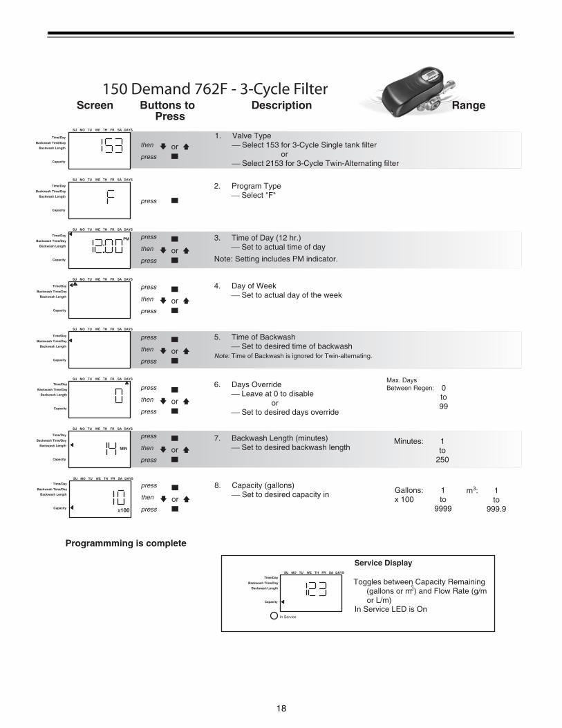
2. Program Type ⎯ Select "F"
3. Time of Day (12 hr.) ⎯ Set to actual time of day
Note: Setting includes PM indicator.
4. Day of Week ⎯ Set to actual day of the week
5. Time of Backwash ⎯ Set to desired time of backwashNote: Time of Backwash is ignored for Twin-alternating.
6. Days Override ⎯ Leave at 0 to disable or ⎯ Set to desired days override
7. Backwash Length (minutes) ⎯ Set to desired backwash length
8. Capacity (gallons) ⎯ Set to desired capacity in
Screen Buttons to Description Range Press
0 to 99
Minutes: 1 to 250
Gallons: 1 x 100 to 9999
Programmming is complete
orpress
then
press
or
press
press
then
or
press
press
then
or
press
press
then
or
press
press
then
or
press
press
then
or
press
press
then
Service Display
PM
Backwash Time/Day
Backwash Length
MIN
X100
150 Demand 762F - 3-Cycle Filter
1. Valve Type ⎯ Select 153 for 3-Cycle Single tank filter or ⎯ Select 2153 for 3-Cycle Twin-Alternating filter
Max. Days Between Regen:
In Service
m3: 1 to 999.9
Time/Day
Capacity
Backwash Time/Day
Backwash Length
Time/Day
Capacity
Backwash Time/Day
Backwash Length
Time/Day
Capacity
Backwash Time/Day
Backwash Length
Time/Day
Capacity
Backwash Time/Day
Backwash Length
Time/Day
Capacity
Backwash Time/Day
Backwash Length
Time/Day
Capacity
Backwash Time/Day
Backwash Length
Time/Day
Capacity
Backwash Time/Day
Backwash Length
Time/Day
Capacity
Backwash Time/Day
Backwash Length
Toggles between Capacity Remaining (gallons or m ) and Flow Rate (g/m or L/m)
In Service LED is On
3
19
Time/Day
SU MO TU WE TH FR SA DAYS
SU MO TU WE TH FR SA DAYS
SU MO TU WE TH FR SA DAYS
SU MO TU WE TH FR SA DAYS
SU MO TU WE TH FR SA DAYS
SU MO TU WE TH FR SA DAYS
SU MO TU WE TH FR SA DAYS
SU MO TU WE TH FR SA DAYS
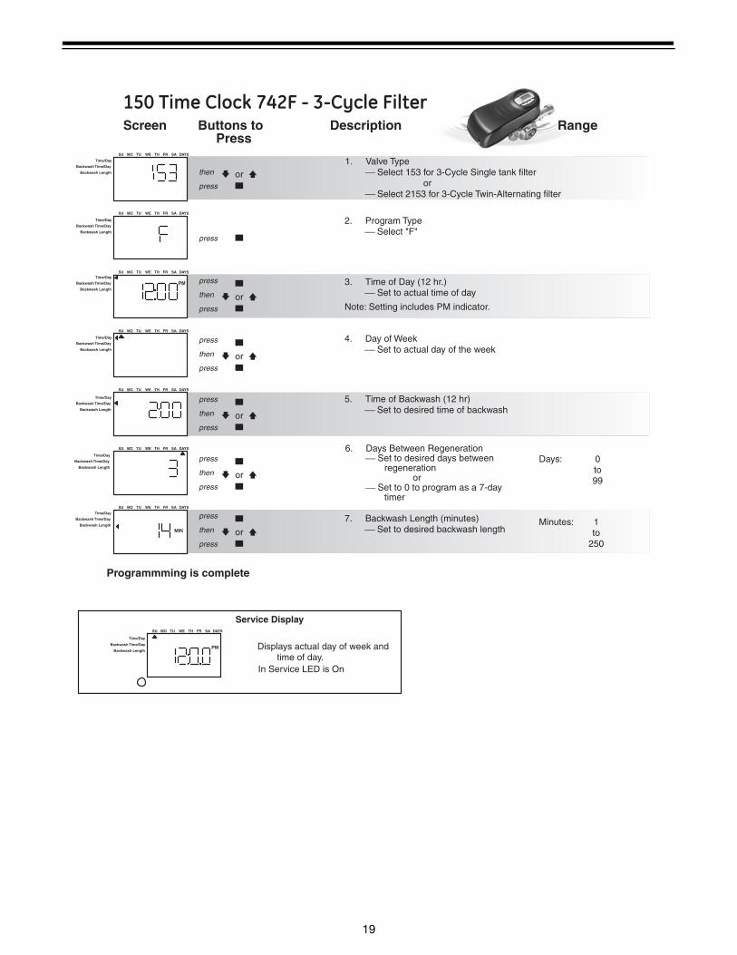
2. Program Type ⎯ Select "F"
3. Time of Day (12 hr.) ⎯ Set to actual time of day
Note: Setting includes PM indicator.
4. Day of Week ⎯ Set to actual day of the week
5. Time of Backwash (12 hr) ⎯ Set to desired time of backwash
6. Days Between Regeneration ⎯ Set to desired days between regeneration or ⎯ Set to 0 to program as a 7-day timer
7. Backwash Length (minutes) ⎯ Set to desired backwash length
Screen Buttons to Description Range Press
Days: 0 to 99
Minutes: 1 to 250
Programmming is complete
orpress
then
press
or
press
press
then
or
press
press
then
or
press
press
then
or
press
press
then
or
press
press
then
Service Display
Displays actual day of week and time of day.
PM
Backwash Time/Day
Backwash Length
MIN
PM
150 Time Clock 742F - 3-Cycle Filter
1. Valve Type ⎯ Select 153 for 3-Cycle Single tank filter or ⎯ Select 2153 for 3-Cycle Twin-Alternating filter
In Service LED is On
Time/Day
Backwash Time/Day
Backwash Length
Time/Day
Backwash Time/Day
Backwash Length
Time/Day
Backwash Time/Day
Backwash Length
Time/Day
Backwash Time/Day
Backwash Length
Time/Day
Backwash Time/Day
Backwash Length
Time/Day
Backwash Time/Day
Backwash Length
Time/Day
Backwash Time/Day
Backwash Length
20
6.0 Logix ControllerPower Loss Memory Retention
The Logix series controllers feature battery-free time and date retention during the loss of power. This is designed to last a minimum of 8 hours depending on the installation. The controller will continue to keep time and day in dynamic memory while there is no AC power.
The controller will not track water usage in the event of a power failure.
Information entered or calculated by the controller is stored in two different ways.
A static memory will store:
Media volumeRegenerant setting Time of regenerationDays between regeneration Filter mode
A dynamic memory with 8 hour retention will store:
Current day of weekRunning clock
Variable Reserve Function
The Logix (762) control is designed to have a variable reserve feature. This feature automatically adjusts the reserve to the end-user’s water usage schedule.
Each day the controller reviews the last four weeks of water usage for the same day of the week to determine if the remaining capacity is adequate for the next day. If not, it will initiate an automatic regeneration.
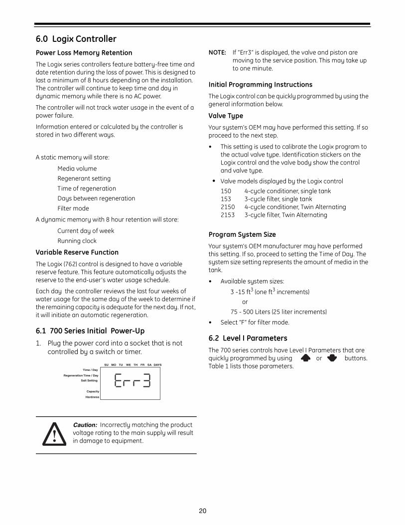
6.1 700 Series Initial Power-Up1. Plug the power cord into a socket that is not
controlled by a switch or timer.
Caution: Incorrectly matching the product voltage rating to the main supply will result in damage to equipment.
NOTE: If “Err3” is displayed, the valve and piston are moving to the service position. This may take up to one minute.
Initial Programming Instructions
The Logix control can be quickly programmed by using the general information below.
Valve Type
Your system’s OEM may have performed this setting. If so proceed to the next step.
• This setting is used to calibrate the Logix program to the actual valve type. Identification stickers on the Logix control and the valve body show the control and valve type.
• Valve models displayed by the Logix control150 4-cycle conditioner, single tank153 3-cycle filter, single tank2150 4-cycle conditioner, Twin Alternating2153 3-cycle filter, Twin Alternating
Program System Size
Your system’s OEM manufacturer may have performed this setting. If so, proceed to setting the Time of Day. The system size setting represents the amount of media in the tank.
• Available system sizes:
3 -15 ft3 (one ft3 increments)or
75 - 500 Liters (25 liter increments)
• Select “F” for filter mode.
6.2 Level I ParametersThe 700 series controls have Level I Parameters that are quickly programmed by using or buttons. Table 1 lists those parameters.
Time / Day
Regeneration Time / Day
Salt Setting
Capacity
Hardness
SU MO TU WE TH FR SA DAYS
21
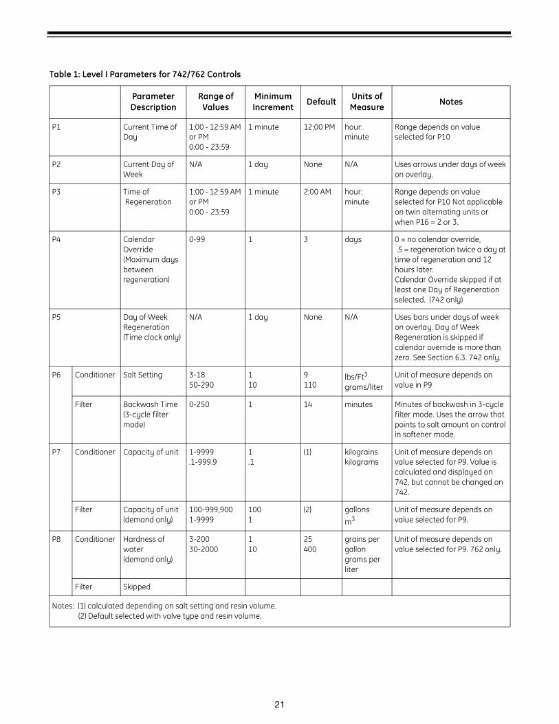
Table 1: Level I Parameters for 742/762 Controls
ParameterDescription
Range of Values
Minimum Increment Default Units of
Measure Notes
P1 Current Time of Day
1:00 - 12:59 AM or PM 0:00 - 23:59
1 minute 12:00 PM hour:minute
Range depends on value selected for P10
P2 Current Day of Week
N/A 1 day None N/A Uses arrows under days of week on overlay.
P3 Time of Regeneration
1:00 - 12:59 AM or PM 0:00 - 23:59
1 minute 2:00 AM hour:minute
Range depends on value selected for P10 Not applicable on twin alternating units or when P16 = 2 or 3.
P4 Calendar Override(Maximum days between regeneration)
0-99 1 3 days 0 = no calendar override, .5 = regeneration twice a day at time of regeneration and 12 hours later. Calendar Override skipped if at least one Day of Regeneration selected. (742 only)
P5 Day of Week Regeneration(Time clock only)
N/A 1 day None N/A Uses bars under days of week on overlay. Day of Week Regeneration is skipped if calendar override is more than zero. See Section 6.3. 742 only.
P6 Conditioner Salt Setting 3-1850-290
110
9110
lbs/Ft3
grams/literUnit of measure depends on value in P9
Filter Backwash Time (3-cycle filter mode)
0-250 1 14 minutes Minutes of backwash in 3-cycle filter mode. Uses the arrow that points to salt amount on control in softener mode.
P7 Conditioner Capacity of unit 1-9999.1-999.9
1.1
(1) kilograinskilograms
Unit of measure depends on value selected for P9. Value is calculated and displayed on 742, but cannot be changed on 742.
Filter Capacity of unit (demand only)
100-999,9001-9999
1001
(2) gallons m3
Unit of measure depends on value selected for P9.
P8 Conditioner Hardness of water(demand only)
3-20030-2000
110
25400
grains per gallongrams per liter
Unit of measure depends on value selected for P9. 762 only.
Filter Skipped
Notes: (1) calculated depending on salt setting and resin volume.(2) Default selected with valve type and resin volume.
22
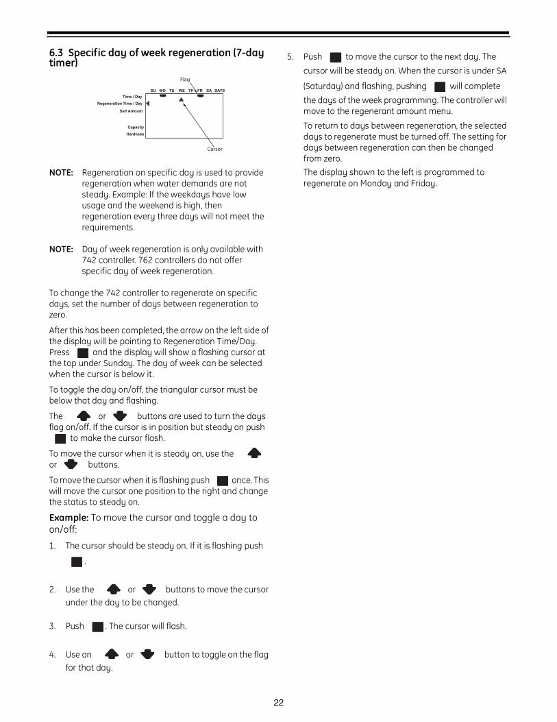
6.3 Specific day of week regeneration (7-day timer)
NOTE: Regeneration on specific day is used to provide regeneration when water demands are not steady. Example: If the weekdays have low usage and the weekend is high, then regeneration every three days will not meet the requirements.
NOTE: Day of week regeneration is only available with 742 controller. 762 controllers do not offer specific day of week regeneration.
To change the 742 controller to regenerate on specific days, set the number of days between regeneration to zero.
After this has been completed, the arrow on the left side of the display will be pointing to Regeneration Time/Day. Press and the display will show a flashing cursor at the top under Sunday. The day of week can be selected when the cursor is below it.
To toggle the day on/off, the triangular cursor must be below that day and flashing.
The or buttons are used to turn the days flag on/off. If the cursor is in position but steady on push
to make the cursor flash.
To move the cursor when it is steady on, use the or buttons.
To move the cursor when it is flashing push once. This will move the cursor one position to the right and change the status to steady on.
Example: To move the cursor and toggle a day to on/off:
1. The cursor should be steady on. If it is flashing push
.
2. Use the or buttons to move the cursor under the day to be changed.
3. Push . The cursor will flash.
4. Use an or button to toggle on the flag for that day.
5. Push to move the cursor to the next day. The
cursor will be steady on. When the cursor is under SA
(Saturday) and flashing, pushing will complete
the days of the week programming. The controller will move to the regenerant amount menu.
To return to days between regeneration, the selected days to regenerate must be turned off. The setting for days between regeneration can then be changed from zero.The display shown to the left is programmed to regenerate on Monday and Friday.
Time / Day
Regeneration Time / Day
Salt Amount
SU MO TU WE TH FR SA DAYS
Capacity
Hardness
Cursor
Flag

23
7.0 Things You Might Need to Know
• When the controller is first plugged in, it may display a flashing hourglass and the message Err 3, this means that the controller is rotating to the home position. If the Err 2 is displayed, check that the incoming power frequency matches the controller. The North American controller does not run with 50 Hz input .
• The preset default time of regeneration is 2:00 AM.
• English or Metric? The World controller senses the electrical input and decides which is needed. The North American controller only runs on 60 Hz and defaults to English units.
• The Logix 742 Series controller can be programmed to regenerate on specific days of the week.
• The Logix Series controllers send commands to the motor for piston movement. However, water pressure/flow are required during the regeneration cycle for backwash, purge and refill, and brine draw to actually take place.
• Make sure control power source is plugged in. The transformer should be connected to a non-switched power source.
• You can start programming at the beginning by resetting the amount of media. When viewing H0 (History Value) push and hold SET for five seconds. The display reverts back to --- and any programmed information is lost. Return to Programming Your Control.
24
8.0 Placing Conditioner Into Operation1. Make sure to rinse out all debris from piping before
connecting the valve.
2. Close inlet , outlet and brine valves.
3. Supply power to timer.
4. Hold the button on the controller until it indicates that the motor is moving the valve to the backwash position (C1) by flashing an hourglass.
5. Fill the media tank with water.
A. While the controller is in cycle C1 (Backwash), open the water supply valve very slowly to approximately the 1/4 open position.
Caution: If opened too rapidly or too far, media may be lost out of the tank into the valve or the plumbing. In the 1/4 open position, you should hear air slowly escaping from the valve drain line.
B. When all of the air has been purged from the media tank (water begins to flow steadily from the drain line), open the main supply valve all of the way. This will purge the final air from the tank.
C. Allow water to run to drain until the water runs clear from the drain line. This purges any refuse from the media bed.
D. Turn off the water supply and let the system stand for about five minutes. This will allow for any air trapped to escape from tank.
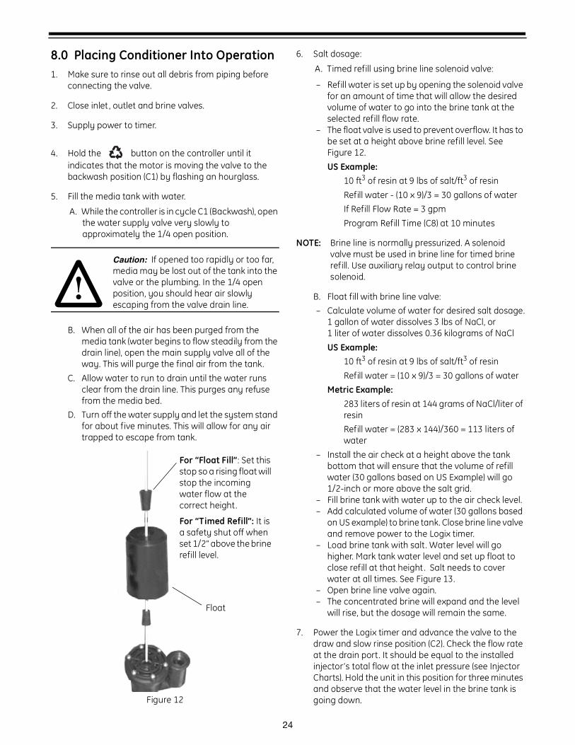
Figure 12
6. Salt dosage:
A. Timed refill using brine line solenoid valve:
– Refill water is set up by opening the solenoid valve for an amount of time that will allow the desired volume of water to go into the brine tank at the selected refill flow rate.
– The float valve is used to prevent overflow. It has to be set at a height above brine refill level. See Figure 12.US Example:
10 ft3 of resin at 9 lbs of salt/ft3 of resinRefill water - (10 x 9)/3 = 30 gallons of waterIf Refill Flow Rate = 3 gpmProgram Refill Time (C8) at 10 minutes
NOTE: Brine line is normally pressurized. A solenoid valve must be used in brine line for timed brine refill. Use auxiliary relay output to control brine solenoid.
B. Float fill with brine line valve:– Calculate volume of water for desired salt dosage.
1 gallon of water dissolves 3 lbs of NaCl, or1 liter of water dissolves 0.36 kilograms of NaClUS Example:
10 ft3 of resin at 9 lbs of salt/ft3 of resinRefill water = (10 x 9)/3 = 30 gallons of water
Metric Example:283 liters of resin at 144 grams of NaCl/liter of resinRefill water = (283 x 144)/360 = 113 liters of water
– Install the air check at a height above the tank bottom that will ensure that the volume of refill water (30 gallons based on US Example) will go 1/2-inch or more above the salt grid.
– Fill brine tank with water up to the air check level.– Add calculated volume of water (30 gallons based
on US example) to brine tank. Close brine line valve and remove power to the Logix timer.
– Load brine tank with salt. Water level will go higher. Mark tank water level and set up float to close refill at that height . Salt needs to cover water at all times. See Figure 13.
– Open brine line valve again.– The concentrated brine will expand and the level
will rise, but the dosage will remain the same.
7. Power the Logix timer and advance the valve to the draw and slow rinse position (C2). Check the flow rate at the drain port. It should be equal to the installed injector’s total flow at the inlet pressure (see Injector Charts). Hold the unit in this position for three minutes and observe that the water level in the brine tank is going down.
For “Float Fill”: Set this stop so a rising float will stop the incoming water flow at the correct height.
For “Timed Refill”: It is a safety shut off when set 1/2” above the brine refill level.
Float

25
8. Advance the valve to the service position.
Figure 13
9. Open the nearest faucet in the service line to drain and run the water until it comes out clear.
10. Restrict the inlet water and move the valve to the backwash position to remove any crown of air left in the tank.
11. Set the valve back to the service position.
Brine/WaterFlow
Calculated Volume(30 gals based on US example)
Salt Grid
Air Check Height
Min. 1/2"
Tank

26
9.0 Regeneration ModesThe 700 Series controllers can be regenerated either automatically or manually. During a regeneration, the total time remaining of the regeneration is displayed on the controller. The current cycle is shown in the lower left of the display.
"Keys" are listed as:
UP for up arrow
DOWN for down arrow
SET for set
REGEN for regeneration
Manual Regeneration:
Delayed Manual Regeneration — Pressing the key programs a delayed manual regeneration. The regeneration icon on the LCD flashes indicating that a regeneration starts when the time of day reaches the programmed time of regeneration. Pressing the key again turns off the regeneration icon and cancels the delayed regeneration.
Immediate Manual Regeneration — Pressing and holding the key for three seconds initiates an immediate manual regeneration. The regeneration icon on the LCD turns on. The control goes to the regenerating mode.
Delayed Second Regeneration — Pressing the key while the control is in the regenerating mode programs a delayed second regeneration. The x2 icon next to the regeneration icon flashes indicating a second regeneration starts when the time of day reaches the programmed time of regeneration.
Double Immediate Manual Regeneration — Pressing and holding the key for three seconds while the control is in the regenerating mode programs back-to-back manual regenerations. The x2 icon next to the regeneration icon turns on indicating a second manual regeneration starts immediately after the current regeneration is complete.
During a Regeneration:
• A "C#" is displayed to show current cycle.
• Total regen time remaining is displayed on screen.
• Press and hold to show current cycle time remaining.
To Advance Regeneration Cycles:
• Simultaneously press and to advance one cycle. An hourglass displays while the cam is advancing.
Repeat and to advance through each cycle.
To Cancel Regeneration:
• Press and hold and for 5 seconds to cancel regen.Hourglass flashes once cancelled.Motor advances the cam to home – may take 1 to 2 minutes.
NOTE: If a second regeneration was programmed, each regeneration must be canceled separately.
NOTE: Canceling a regeneration may cause undesirable or salty water to go into service. Use only when necessary.
Regeneration Cycles:
• C1 – Backwash
• C2 – Regeneration Draw/Slow Rinse (not used in filter mode)
• C3 – Slow Rinse (not used in filter mode)
• C5 – Fast Rinse cycle
• C8 – Regenerant Refill (not used in filter mode)
Time / Day
Regeneration Time / Day
Salt
SU MO TU WE TH FR SA DAYS
CCapacity
Hardness
MIN
x2
Total regeneration time remaining
27
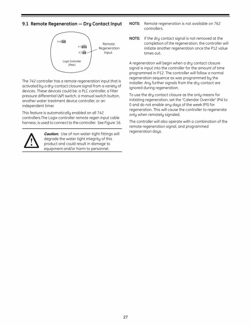
9.1 Remote Regeneration — Dry Contact Input
The 742 controller has a remote regeneration input that is activated by a dry-contact closure signal from a variety of devices. These devices could be: a PLC controller, a filter pressure differential (ΔP) switch, a manual switch button, another water treatment device controller, or an independent timer.
This feature is automatically enabled on all 742 controllers.The Logix controller remote regen input cable harness, is used to connect to the controller. See Figure 16.
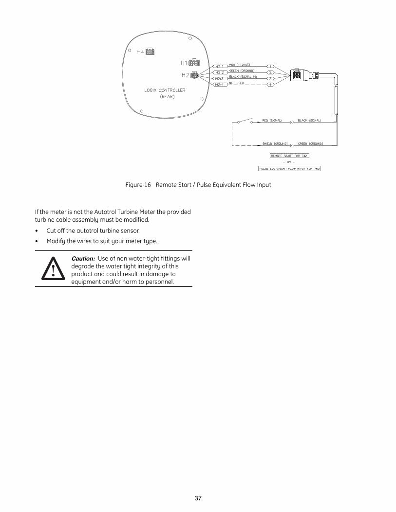
Caution: Use of non water-tight fittings will degrade the water tight integrity of this product and could result in damage to equipment and/or harm to personnel.
NOTE: Remote regeneration is not available on 762 controllers.
NOTE: If the dry contact signal is not removed at the completion of the regeneration, the controller will initiate another regeneration once the P12 value times out.
A regeneration will begin when a dry contact closure signal is input into the controller for the amount of time programmed in P12. The controller will follow a normal regeneration sequence as was programmed by the installer. Any further signals from the dry contact are ignored during regeneration.
To use the dry contact closure as the only means for initiating regeneration, set the "Calendar Override" (P4) to 0 and do not enable any days of the week (P5) for regeneration. This will cause the controller to regenerate only when remotely signaled.
The controller will also operate with a combination of the remote regeneration signal, and programmed regeneration days.
Logix Controller(Rear)
RemoteRegeneration
Input
28
10.0 Programming the Logix for Manganese Greensand SystemsManganese Greensand Systems
Sizing 5-Cycle Filters
Potassium permanganate regenerating iron filters should be sized for the appropriate backwash and injector sizes.
Backwash Controller
Be sure to choose the appropriate backwash flow rate control (see Parts section) as recommended by your media manufacturer.
Injector
Use the same injector size as you would for your conditioner control tank diameter.
Refill Controller
The refill flow rate is controlled by the injector. Use a float valve in your potassium permanganate feeder to set potassium permanganate dosage.
Initial Resin Volume Setting
Programming for a manganese greensand system requires a few minor adjustments to the programming to operate the control correctly. The initial resin volume should be set to the closest volume of the manganese greensand in the system. For example, if the system contains four cubic feet of manganese greensand, program in 4.00 for the resin volume.
"Salt" Setting for KMNO4 Regenerant
Be sure to set the salt dosage high enough to operate the float shut-off in the regenerant storage tank.
All other settings remain the same as mentioned in the previous programming sections.
Days Between Regeneration Setting (742)
To set the days between regenerations, consult the media manufacturer for the actual capacity of the media.
In general, manganese greensand has a capacity of 10,000 ppm of removal capability per cubic foot of media. Calculate the capacity of the system by taking the number of cubic feet of media and multiply by 10,000.
For example, using a 1 cubic foot system provides 10,000 ppm of removal capability.
The next step is to calculate the demand for the system. Multiply the predicted daily water usage by the iron content in ppm.
For example, an average person uses 75 gallons of water per day. Four people living in a home use 300 gallons of water (75 gallons x 4 people) per day. Assume the incoming water has 10 ppm of iron. Now calculate the daily demand: multiply the gallons of water used per day (300) by the ppm of iron content (10) = 3000 ppm of daily capacity usage.
Now take the system capacity (10,000), divided by the daily demand (3,000) = 3.3 days of capacity. Since you run out of capacity before the beginning of the fourth day, the proper setting for days between regeneration is 3 days.
For example:
4 people x 75 gals per person = 300 gallons used
per day.
10 ppm iron x 300 gal/day = 3000 ppm/day
10,000 ppm capacity ÷ 3000 ppm/day = 3.3 days of
total capacity
Solution = regenerate every 3 days.
The above capacity numbers are based only on Fe. For removal of H2S and Mn refer to the media manufacturers specifications.
Volume/Demand Regeneration Setting (762)
To set a 762 demand system for iron removal you must:
1. Know your media capacity. Generally, one cubic foot of magnesium greensand can remove 10,000 ppm of iron.
2. Know the iron concentration in your water.
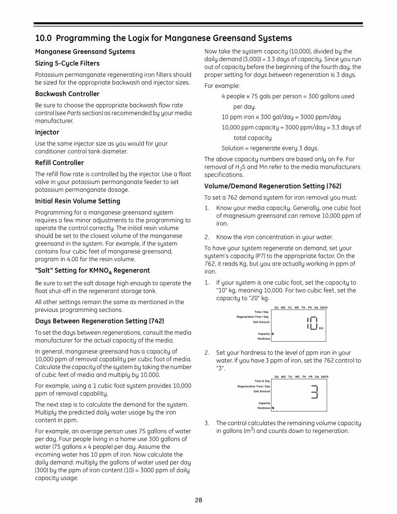
To have your system regenerate on demand, set your system’s capacity (P7) to the appropriate factor. On the 762, it reads Kg, but you are actually working in ppm of iron.
1. If your system is one cubic foot, set the capacity to "10" kg, meaning 10,000. For two cubic feet, set the capacity to "20" kg.
2. Set your hardness to the level of ppm iron in your water. If you have 3 ppm of iron, set the 762 control to "3".
3. The control calculates the remaining volume capacity in gallons (m3) and counts down to regeneration.
Time / Day
Regeneration Time / Day
Salt Amount
SU MO TU WE TH FR SA DAYS
Capacity
Hardness
KG
Time & Day
Salt Amount
SU MO TU WE TH FR SA DAYS
Capacity
Hardness
Regeneration Time / Day
29
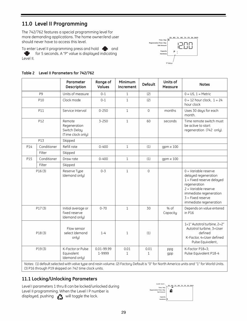
11.0 Level II ProgrammingThe 742/762 features a special programming level for more demanding applications. The home owner/end user should never have to access this level.
To enter Level II programming press and hold and for 5 seconds. A "P" value is displayed indicating
Level II.
11.1 Locking/Unlocking ParametersLevel I parameters 1 thru 8 can be locked/unlocked during Level II programming. When the Level I P number is displayed, pushing will toggle the lock.
Time / Day
Salt Amount
SU MO TU WE TH FR SA DAYS
PCapacity
Hardness
P Value
Regeneration Time / Day
Table 2 Level II Parameters for 742/762
ParameterDescription
Range of Values
Minimum Increment Default Units of
Measure Notes
P9 Units of measure 0-1 1 (2) 0 = US, 1 = Metric
P10 Clock mode 0-1 1 (2) 0 = 12 hour clock, 1 = 24 hour clock
P11 Service Interval 0-250 1 0 months Uses 30 days for each month.
P12 Remote RegenerationSwitch Delay(Time clock only)
3-250 1 60 seconds Time remote switch must be active to start regeneration (742 only).
P13 Skipped
P14 Conditioner Refill rate 0-400 1 (1) gpm x 100
Filter Skipped
P15 Conditioner Draw rate 0-400 1 (1) gpm x 100
Filter Skipped
P16 (3) Reserve Type (demand only)
0-3 1 0 0 = Variable reserve delayed regeneration1 = Fixed reserve delayed regeneration2 = Variable reserve immediate regeneration3 = Fixed reserve immediate regeneration
P17 (3) Initial average or f ixed reserve (demand only)
0-70 1 30 % of Capacity
Depends on value entered in P16
P18 (3)Flow sensor
select (demand only)
1-4 1 (1)
1=1” Autotrol turbine, 2=2” Autotrol turbine, 3=User
defined K-Factor, 4=User defined
Pulse Equivalent,
P19 (3) K-Factor or Pulse Equivalent (demand only)
0.01-99.991-9999
0.011
0.011
ppggpp
K-Factor P18=3;Pulse Equivalent P18-4
Notes: (1) default selected with valve type and resin volume. (2) Factory Default is “0” for North America units and “1” for World Units. (3) P16 through P19 skipped on 742 time clock units.
Time / Day
Salt Amount
SU MO TU WE TH FR SA DAYS
Capacity
Hardness
Lock Icon
Regeneration Time / Day
30
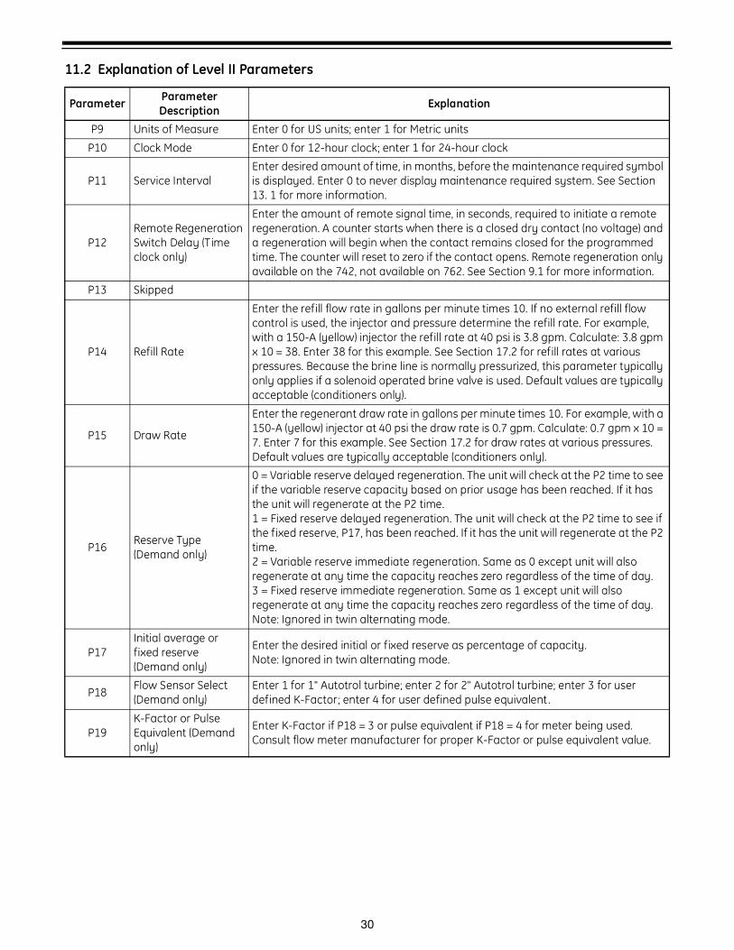
11.2 Explanation of Level II Parameters
Parameter Parameter Description Explanation
P9 Units of Measure Enter 0 for US units; enter 1 for Metric units
P10 Clock Mode Enter 0 for 12-hour clock; enter 1 for 24-hour clock
P11 Service IntervalEnter desired amount of time, in months, before the maintenance required symbol is displayed. Enter 0 to never display maintenance required system. See Section 13. 1 for more information.
P12Remote Regeneration Switch Delay (Time clock only)
Enter the amount of remote signal time, in seconds, required to initiate a remote regeneration. A counter starts when there is a closed dry contact (no voltage) and a regeneration will begin when the contact remains closed for the programmed time. The counter will reset to zero if the contact opens. Remote regeneration only available on the 742, not available on 762. See Section 9.1 for more information.
P13 Skipped
P14 Refill Rate
Enter the refill flow rate in gallons per minute times 10. If no external refill flow control is used, the injector and pressure determine the refill rate. For example, with a 150-A (yellow) injector the refill rate at 40 psi is 3.8 gpm. Calculate: 3.8 gpm x 10 = 38. Enter 38 for this example. See Section 17.2 for refill rates at various pressures. Because the brine line is normally pressurized, this parameter typically only applies if a solenoid operated brine valve is used. Default values are typically acceptable (conditioners only).
P15 Draw Rate
Enter the regenerant draw rate in gallons per minute times 10. For example, with a 150-A (yellow) injector at 40 psi the draw rate is 0.7 gpm. Calculate: 0.7 gpm x 10 = 7. Enter 7 for this example. See Section 17.2 for draw rates at various pressures. Default values are typically acceptable (conditioners only).
P16 Reserve Type (Demand only)
0 = Variable reserve delayed regeneration. The unit will check at the P2 time to see if the variable reserve capacity based on prior usage has been reached. If it has the unit will regenerate at the P2 time.1 = Fixed reserve delayed regeneration. The unit will check at the P2 time to see if the fixed reserve, P17, has been reached. If it has the unit will regenerate at the P2 time.2 = Variable reserve immediate regeneration. Same as 0 except unit will also regenerate at any time the capacity reaches zero regardless of the time of day.3 = Fixed reserve immediate regeneration. Same as 1 except unit will also regenerate at any time the capacity reaches zero regardless of the time of day.Note: Ignored in twin alternating mode.
P17Initial average or fixed reserve (Demand only)
Enter the desired initial or fixed reserve as percentage of capacity.Note: Ignored in twin alternating mode.
P18 Flow Sensor Select (Demand only)
Enter 1 for 1" Autotrol turbine; enter 2 for 2" Autotrol turbine; enter 3 for user defined K-Factor; enter 4 for user defined pulse equivalent .
P19K-Factor or Pulse Equivalent (Demand only)
Enter K-Factor if P18 = 3 or pulse equivalent if P18 = 4 for meter being used. Consult flow meter manufacturer for proper K-Factor or pulse equivalent value.
31
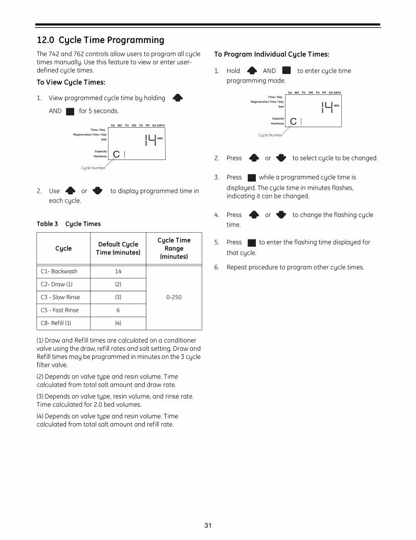
12.0 Cycle Time ProgrammingThe 742 and 762 controls allow users to program all cycle times manually. Use this feature to view or enter user-defined cycle times.
To View Cycle Times:
1. View programmed cycle time by holding
AND for 5 seconds.
2. Use or to display programmed time in each cycle.
(1) Draw and Refill times are calculated on a conditioner valve using the draw, refill rates and salt setting. Draw and Refill times may be programmed in minutes on the 3 cycle filter valve.
(2) Depends on valve type and resin volume. Time calculated from total salt amount and draw rate.
(3) Depends on valve type, resin volume, and rinse rate. Time calculated for 2.0 bed volumes.
(4) Depends on valve type and resin volume. Time calculated from total salt amount and refill rate.
To Program Individual Cycle T imes:
1. Hold AND to enter cycle time programming mode.
2. Press or to select cycle to be changed.
3. Press while a programmed cycle time is
displayed. The cycle time in minutes flashes, indicating it can be changed.
4. Press or to change the flashing cycle time.
5. Press to enter the flashing time displayed for
that cycle.
6. Repeat procedure to program other cycle times.
Table 3 Cycle Times
Cycle Default Cycle Time (minutes)
Cycle Time Range
(minutes)
C1- Backwash 14
0-250
C2- Draw (1) (2)
C3 - Slow Rinse (3)
C5 - Fast Rinse 6
C8- Refill (1) (4)
Time / Day
Salt
SU MO TU WE TH FR SA DAYS
CCapacity
Hardness
MIN
Cycle Number
Regeneration Time / Day
Time / Day
Salt
SU MO TU WE TH FR SA DAYS
CCapacity
Hardness
MIN
Cycle Number
Regeneration Time / Day
32
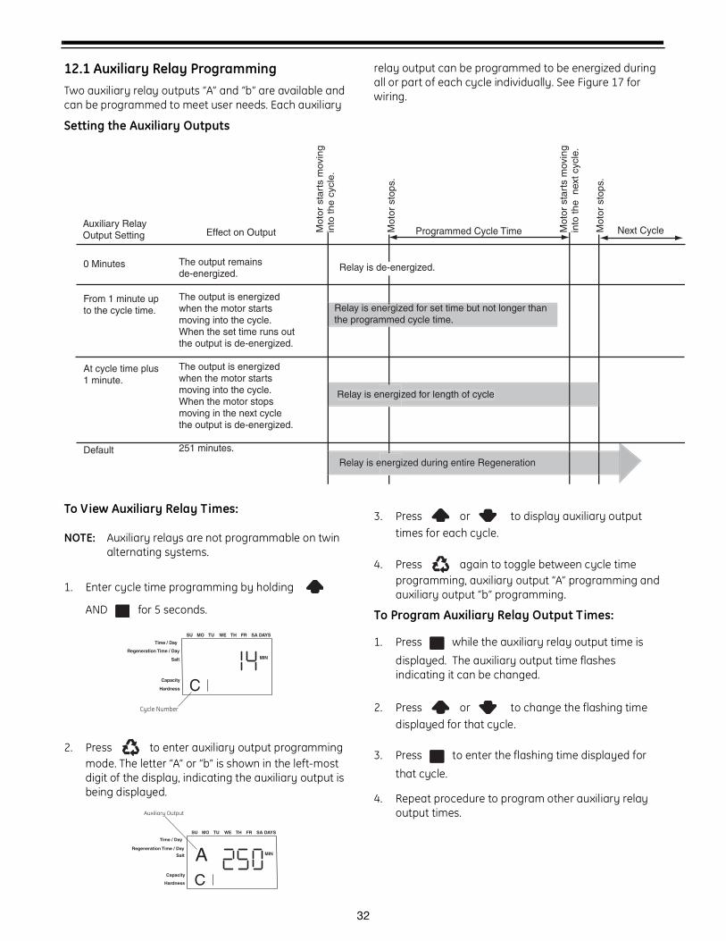
12.1 Auxiliary Relay ProgrammingTwo auxiliary relay outputs “A” and “b” are available and can be programmed to meet user needs. Each auxiliary
relay output can be programmed to be energized during all or part of each cycle individually. See Figure 17 for wiring.
Setting the Auxiliary Outputs
To View Auxiliary Relay Times:
NOTE: Auxiliary relays are not programmable on twin alternating systems.
1. Enter cycle time programming by holding
AND for 5 seconds.
2. Press to enter auxiliary output programming mode. The letter “A” or “b” is shown in the left-most digit of the display, indicating the auxiliary output is being displayed.
3. Press or to display auxiliary output times for each cycle.
4. Press again to toggle between cycle time programming, auxiliary output “A” programming and auxiliary output “b” programming.
To Program Auxiliary Relay Output Times:
1. Press while the auxiliary relay output time is
displayed. The auxiliary output time flashes indicating it can be changed.
2. Press or to change the flashing time displayed for that cycle.
3. Press to enter the flashing time displayed for
that cycle.
4. Repeat procedure to program other auxiliary relay output times.
Moto
r st
art
s m
ovin
g
into
the c
ycle
.
Mot
or s
tops
.
Mot
or s
tart
s m
ovin
g in
to th
e n
ext c
ycle
.
Mot
or s
tops
.
Programmed Cycle Time Next CycleEffect on Output
0 Minutes
From 1 minute up to the cycle time.
At cycle time plus 1 minute.
Default
The output remains de-energized.
The output is energized when the motor starts moving into the cycle. When the set time runs out the output is de-energized.
The output is energized when the motor starts moving into the cycle. When the motor stops moving in the next cycle the output is de-energized.
251 minutes.
Relay is de-energized.
Relay is energized for set time but not longer than the programmed cycle time.
Relay is energized for length of cyclenergiz
Relay is energized during entire Regeneration
Auxiliary RelayOutput Setting
Time / Day
Salt
SU MO TU WE TH FR SA DAYS
CCapacity
Hardness
MIN
Cycle Number
Regeneration Time / Day
Time / Day
Salt
SU MO TU WE TH FR SA DAYS
CCapacity
Hardness
MIN
Auxiliary Output
ARegeneration Time / Day
33
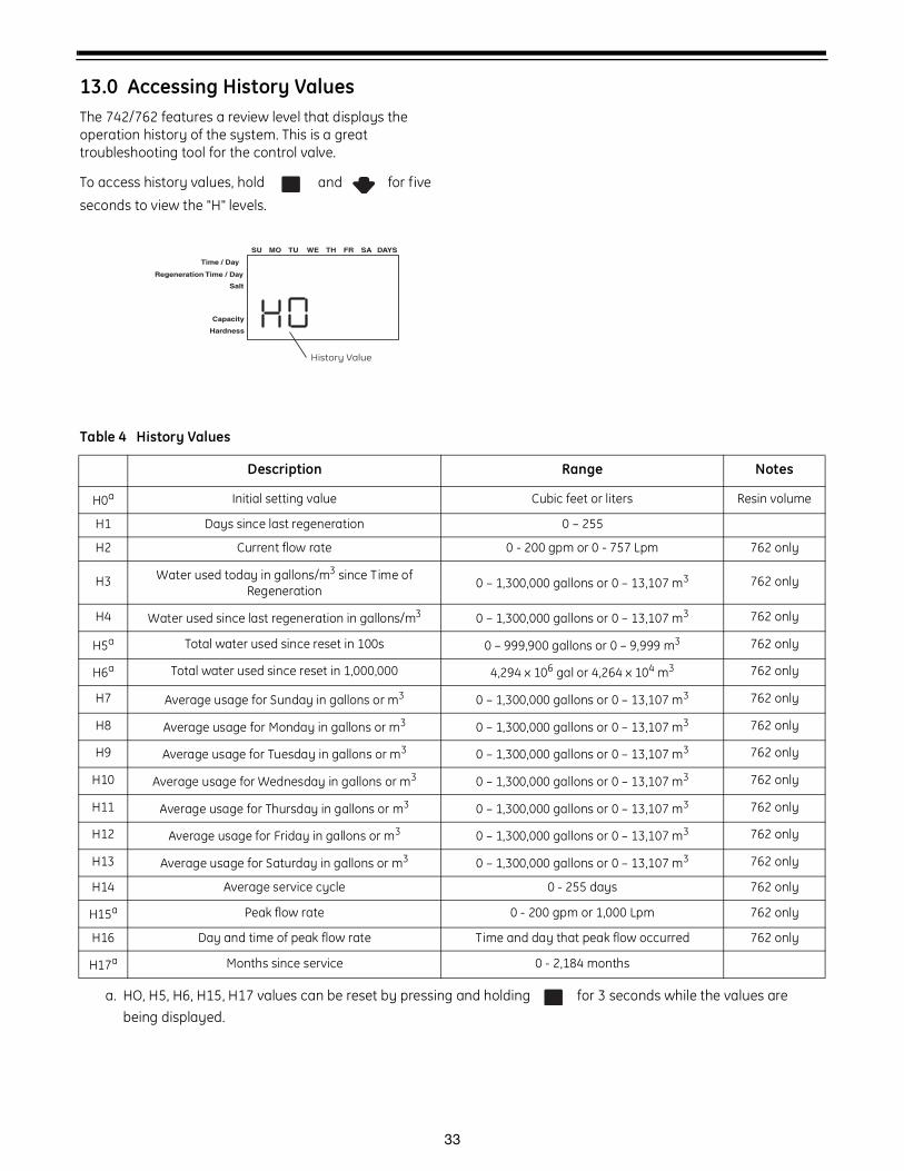
13.0 Accessing History ValuesThe 742/762 features a review level that displays the operation history of the system. This is a great troubleshooting tool for the control valve.
To access history values, hold and for five
seconds to view the "H" levels.
Time / Day
Salt
SU MO TU WE TH FR SA DAYS
Capacity
Hardness
History Value
Regeneration Time / Day
Table 4 History Values
Description Range Notes
H0a Initial setting value Cubic feet or liters Resin volume
H1 Days since last regeneration 0 – 255
H2 Current flow rate 0 - 200 gpm or 0 - 757 Lpm 762 only
H3 Water used today in gallons/m3 since Time of Regeneration 0 – 1,300,000 gallons or 0 – 13,107 m3 762 only
H4 Water used since last regeneration in gallons/m3 0 – 1,300,000 gallons or 0 – 13,107 m3 762 only
H5a Total water used since reset in 100s 0 – 999,900 gallons or 0 – 9,999 m3 762 only
H6a Total water used since reset in 1,000,000 4,294 x 106 gal or 4,264 x 104 m3 762 only
H7 Average usage for Sunday in gallons or m3 0 – 1,300,000 gallons or 0 – 13,107 m3 762 only
H8 Average usage for Monday in gallons or m3 0 – 1,300,000 gallons or 0 – 13,107 m3 762 only
H9 Average usage for Tuesday in gallons or m3 0 – 1,300,000 gallons or 0 – 13,107 m3 762 only
H10 Average usage for Wednesday in gallons or m3 0 – 1,300,000 gallons or 0 – 13,107 m3 762 only
H11 Average usage for Thursday in gallons or m3 0 – 1,300,000 gallons or 0 – 13,107 m3 762 only
H12 Average usage for Friday in gallons or m3 0 – 1,300,000 gallons or 0 – 13,107 m3 762 only
H13 Average usage for Saturday in gallons or m3 0 – 1,300,000 gallons or 0 – 13,107 m3 762 only
H14 Average service cycle 0 - 255 days 762 only
H15a Peak flow rate 0 - 200 gpm or 1,000 Lpm 762 only
H16 Day and time of peak flow rate Time and day that peak flow occurred 762 only
H17a Months since service 0 - 2,184 months
a. HO, H5, H6, H15, H17 values can be reset by pressing and holding for 3 seconds while the values are being displayed.
34
13.1 Maintenance IntervalThe history value P11 may be set to a predetermined interval. The interval (in months) would be determined by a desired maintenance event. When the value for P11 is reached, the display will show
To reset the maintenance interval and clear the display:
1. Access history values by holding AND
for 5 seconds.
2. Use or to show H17.
3. Hold for 3 seconds while H17 is displayed.
35
14.0 Control Reset
NOTE: Resetting the control deletes all information stored in its memory, except time and day. This requires you to reprogram the control completely from the initial power-up mode.
To reset the control back to its original unprogrammed state:
1. Hold AND simultaneously for 5 seconds.
2. H0 and the system’s set resin volume (or “F” mode) is displayed.
3. If a history value other the “H0” is displayed, use the button to scroll through the settings until “H0”
is displayed.
4. To reset the control, hold for 5 seconds.
5. The display will show a flashing “150” indicating it is reset to an unprogrammed state.
6. Go to “Initial Set-up” section to reprogram control.
36
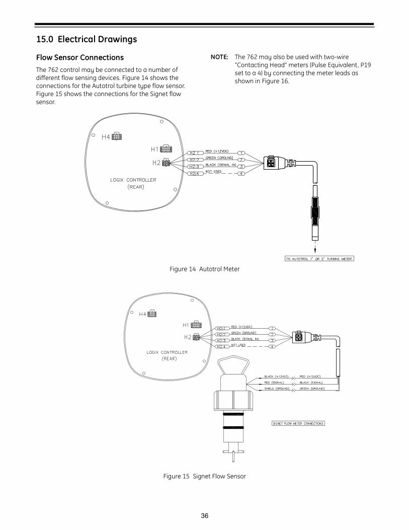
15.0 Electrical Drawings
Flow Sensor ConnectionsThe 762 control may be connected to a number of different flow sensing devices. Figure 14 shows the connections for the Autotrol turbine type flow sensor. Figure 15 shows the connections for the Signet flow sensor.
NOTE: The 762 may also be used with two-wire “Contacting Head” meters (Pulse Equivalent, P19 set to a 4) by connecting the meter leads as shown in Figure 16.
Figure 14 Autotrol Meter
Figure 15 Signet Flow Sensor
37
Figure 16 Remote Start / Pulse Equivalent Flow Input
If the meter is not the Autotrol Turbine Meter the provided turbine cable assembly must be modified.
• Cut off the autotrol turbine sensor.
• Modify the wires to suit your meter type.
Caution: Use of non water-tight fittings will degrade the water tight integrity of this product and could result in damage to equipment and/or harm to personnel.
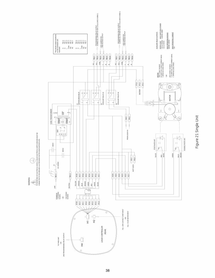
38
WA
RNIN
G
TO A
VO
ID R
ISK
OF
ELEC
TRIC
AL
SHO
CK
, A V
ALI
D E
LEC
TRIC
AL
EART
H G
ROU
ND
MU
ST B
E
CO
NN
ECTE
D T
O T
HE
GRO
UN
D L
UG
PRO
VID
ED O
N T
HE
VALV
E M
OTO
R PL
ATE.
5A 2
50VA
C
F1
34 6
25
1
SW1
1
6 5
32 4189
12VA
C 0
.4A
PRIM
ARY
50/6
0HZ
PRIM
ARY
50/6
0HZ
T17
MO
V1
MO
V2
4
53
12
K1
MO
TOR
DRI
VE
RELA
Y
4
53
12
K2
AU
XIL
IARY
REL
AY #
A
AD
D J
UM
PER
FOR
LIN
E V
OLT
AG
E O
UTP
UT
PRO
GR
AM
MA
BLE
REL
AY O
UTP
UT
DU
RIN
G A
LL O
R PA
RT O
F A
NY
CYC
LE (S
PDT,
FO
RM C
)
AU
XIL
IARY
REL
AY O
UTP
UTS
RAT
ED L
OA
D
M
AX
SW
ITC
HIN
G P
OW
ER12
A a
t 25
0VA
C
3,0
00VA
, 288
W12
A a
t 30
VD
C
MA
X O
PER
ATIN
G V
OLT
AG
E38
0VA
C, 6
0VD
C
MA
X O
PER
ATIN
G C
URR
ENT
12A
CO
M.
TB2:
4
TB2:
1
TB2:
5
TB2:
6
TB2:
2
TB2:
3
N.O
.
N.C
.
L. N.
N.
H2:
2
H2:
5
H2:
4
H2:
3
H2:
6
H2:
1
H1:
1
H1:
4
H1:
7
H1:
5
H1:
3
H1:
2
H1:
8
H1:
6
LOG
IX C
ON
TRO
LLER
(REA
R)
H4
H1 H2
BLA
CK
WH
ITE
RED
GRE
EN
BRO
WN
BLU
E
ORA
NG
E
YEL
LOW
TO T
WIN
UN
IT
742
= D
RY C
ON
TAC
T ST
ART
INPU
T
H1:
2
H1:
6
H1:
7
H1:
4
H1:
3
H1:
5
H1:
8
H1:
1
762
= F
LOW
MET
ER IN
PUT
- OR
-
TB1:
2N
EUTR
AL
POW
ER IN
115/
230V
AC
50/6
0Hz
- OR
-
100/
200V
AC
50/6
0HZ
TB1:
1LI
NE
H3:
1
H3:
2(N
OT
USE
D)
GRE
EN
BRO
WN
BLU
E
BLA
CK
RED
WH
ITE
STO
P PH
OTO
-IN
T
HO
MIN
G P
HO
TO-I
NT
MO
TOR
MO
TOR
P1:1
P1:3
P1:2
2 1
MO
TOR
100/
115V
AC
50/
60H
Z2.
8 A
MP
FULL
LO
AD
CU
RREN
T (M
AX
)1.
4RPM
NO
LO
AD
SPE
ED
- OR
-
200/
230V
AC
50/
60H
Z1.
25 A
MP
FULL
LO
AD
CU
RREN
T (M
AX
)1.
1RPM
NO
LO
AD
SPE
ED
12VA
C T
RAN
SFO
RMER
- OR
-
2N
D P
ROG
RA
MM
AB
LE R
ELAY
OU
TPU
T
AD
D J
UM
PER
FOR
LIN
E V
OLT
AG
E O
UTP
UT
PRO
GR
AM
MA
BLE
REL
AY O
UTP
UT
DU
RIN
G A
LL O
R PA
RT O
F A
NY
CYC
LE (S
PDT,
FO
RM C
)
CO
M.
TB3:
4
TB3:
1
TB3:
5
TB3:
6
TB3:
2
TB3:
3
N.O
.
N.C
.
L. N.
N.
H4:
1
H4:
2
4
53
12
FRO
M L
OG
IX H
4
K2
AU
XIL
IARY
REL
AY #
b
N
TB2
:6N
TB
2 :5
L TB
2 :4
CO
M
TB2
:3N
O
TB2
:2N
C
TB2
:1
N
TB3
:6N
TB
3 :5
L TB
3 :4
CO
M
TB3
:3N
O
TB3
:2N
C
TB3
:1
The
act
ual o
utpu
t pos
ition
son
the
hard
war
e ar
e re
vers
ed.
Figu
re 2
1 Si
ngle
Uni
t
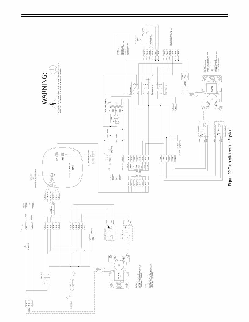
39
TO
AV
OID
RIS
K O
F EL
ECTR
ICA
L SH
OC
K, A
VA
LID
ELE
CTR
ICA
L EA
RTH
GR
OU
ND
MU
ST B
E C
ON
NEC
TED
TO
TH
E G
RO
UN
D L
UG
PR
OV
IDED
ON
TH
E V
ALV
E M
OTO
R P
LATE
.
IN S
ERV
ICE
LED
H3:
1
H2:
2
H2:
5
H1:
5
H1:
2
TB1:
1
P2:1
P1:2
P1:3
H3:
2
H2:
6
H2:
4
H2:
3
H1:
4
H1:
6
H1:
1
TB1:
2
1K 0
.25WR
1
P2:2
P1:1
H2:
1
H1:
3
4
53
12
K1
DR
IVE
REL
AY
TWIN
CA
BLE
MO
TOR
GR
EEN
BR
OW
N
BLU
E
BLA
CK
RED
WH
ITE
1 2ST
OP
PHO
TO-I
NT
HO
MIN
G P
HO
TO-I
NT
#2
(NO
T U
SED
)
MO
TOR
LIN
E
NEU
TRA
L
POW
ER IN
115/
230V
AC
50/6
0Hz
- OR
-
100/
200V
AC
50/6
0HZ
MO
TOR
100/
115V
AC
50/
60H
Z2.
8 A
MP
FULL
LO
AD
CU
RR
ENT
(MA
X)
1.4R
PM N
O L
OA
D S
PEED
- OR
-
200/
230V
AC
50/
60H
Z1.
25 A
MP
FULL
LO
AD
CU
RR
ENT
(MA
X)
1.1R
PM N
O L
OA
D S
PEED
H1:
4
H1:
1
H1:
3
H1:
5
H1:
6
H1:
2
INTE
RC
ON
NEC
T
AD
D J
UM
PER
FO
RLI
NE
VO
LTA
GE
OU
TPU
T
AU
XIL
IAR
Y
REL
AY
OU
TPU
T
RA
TED
LO
AD
MA
X
SWIT
CH
ING
PO
WER
12A
at
250V
AC
3
,000
VA
, 288
W12
A a
t 30
VD
C
MA
X O
PERA
TIN
G V
OLT
AG
E38
0VA
C, 6
0VD
C
5A 2
50V
AC
F1
34 6
25
1
SW1
1
6 5
32 4189
12V
AC
0.4
A
PRIM
AR
Y50
/60H
Z
PRIM
AR
Y50
/60H
Z
T17
MO
V1
MO
V2
4
53
12
K1
MO
TOR
DRI
VE
RELA
Y 4
53
12
K2
AU
XIL
IAR
Y R
ELA
Y #
1
CO
M.
TB2:
4
TB2:
1
TB2:
5
TB2:
6
TB2:
2
TB2:
3
N.O
.
N.C
.
L. N.
N.
H2:
2
H2:
5
H2:
4
H2:
3
H2:
6
H2:
1
H1:
1
H1:
4
H1:
7
H1:
5
H1:
3
H1:
2
H1:
8
H1:
6
LOG
IX C
ON
TRO
LLER
(REA
R)
H4
H1 H2
BLA
CK
WH
ITE
RED
GRE
EN
BRO
WN
BLU
E
ORA
NG
E
YEL
LOW
TO T
WIN
UN
IT
742
= D
RY C
ON
TAC
T ST
ART
INPU
T
H1:
2
H1:
6
H1:
7
H1:
4
H1:
3
H1:
5
H1:
8
H1:
1
762
= F
LOW
MET
ER IN
PUT
- OR
-
TB1:
2N
EUTR
AL
POW
ER IN
115/
230V
AC
50/6
0Hz
- OR
-
100/
200V
AC
50/6
0HZ
TB1:
1LI
NE
H3:
1
H3:
2(N
OT
USE
D)
GRE
EN
BRO
WN
BLU
E
BLA
CK
RED
WH
ITE
STO
P PH
OTO
-IN
T
HO
MIN
G P
HO
TO-I
NT
MO
TOR
MO
TOR
P1:1
P1:3
P1:2
2 1
MO
TOR
100/
115V
AC
50/
60H
Z2.
8 A
MP
FULL
LO
AD
CU
RR
ENT
(MA
X)
1.4R
PM N
O L
OA
D S
PEED
- OR
-
200/
230V
AC
50/
60H
Z1.
25 A
MP
FULL
LO
AD
CU
RR
ENT
(MA
X)
1.1R
PM N
O L
OA
D S
PEED
12V
AC
TR
AN
SFO
RM
ER
- OR
-
2ND
PRO
GRA
MM
AB
LE R
ELA
Y O
UTP
UT
SER
VIC
E SO
LEN
OID
TAN
K 2
SER
VIC
E SO
LEN
OID
TAN
K 1
4
53
12
K2
AU
XIL
IARY
REL
AY
#2
H4:
1
H4:
2
CO
M.
TB3:
4
TB3:
1
TB3:
5
TB3:
6
TB3:
2
TB3:
3
N.O
.
N.C
.
L. N.
N.
5A 2
50V
AC
F2
WA
RN
ING
:
NO
TE: A
UX
ILIA
RY
REL
AY
"B
" IS
NO
T EN
ERG
IZED
IN T
WIN
ALT
ERN
ATI
NG
MO
DE.
Figu
re 2
2 Tw
in A
ltern
atin
g Sy
stem
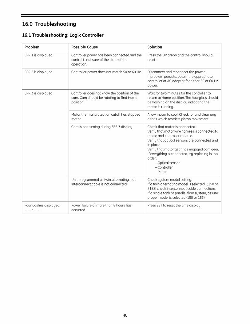
40
16.0 Troubleshooting
16.1 Troubleshooting: Logix Controller
Problem Possible Cause Solution
ERR 1 is displayed Controller power has been connected and the control is not sure of the state of the operation.
Press the UP arrow and the control should reset.
ERR 2 is displayed Controller power does not match 50 or 60 Hz. Disconnect and reconnect the power.If problem persists, obtain the appropriate controller or AC adapter for either 50 or 60 Hz power.
ERR 3 is displayed Controller does not know the position of the cam. Cam should be rotating to find Home position.
Wait for two minutes for the controller to return to Home position. The hourglass should be flashing on the display indicating the motor is running.
Motor thermal protection cutoff has stopped motor.
Allow motor to cool. Check for and clear any debris which restricts piston movement.
Cam is not turning during ERR 3 display. Check that motor is connected.Verify that motor wire harness is connected to motor and controller module.Verify that optical sensors are connected and in place. Verify that motor gear has engaged cam gear.If everything is connected, try replacing in this order:
—Optical sensor—Controller—Motor
Unit programmed as twin alternating, but interconnect cable is not connected.
Check system model setting.If a twin alternating model is selected (2150 or 2153) check interconnect cable connections.If a single tank or parallel flow system, assure proper model is selected (150 or 153).
Four dashes displayed:— — : — —
Power failure of more than 8 hours has occurred
Press SET to reset the time display.

41
16.2 Troubleshooting: 150 Valve
Problem Possible Cause Solution
No soft water ORWater conditioner fails to regenerate.
a. Manual bypass valve is open .
b. Power supply interruption.
c. Blown fuse.
d. Water pressure lost.
e. Insufficient brine .
f. No salt in brine tank.
g. Control improperly programmed.
h. If a metered unit, flow meter not connected to control.
i. If a metered unit, flow meter is clogged or restricted.
j. Leak at riser pipe seal.
k. Plugged injector or injector screen.
l. Salt bridging.
m. Brine line shut off valve closed.
n. Cross connection in service line .
o. Brine director malfunctioning on multiple tank systems sharing a brine tank.
a. Close manual bypass valve.
b. Determine reason for power interruption and correct. Reset time of day if required.
c. Replace blown fuse. Correct cause of excessive current draw. Reset time of day if required.
d. Restore water pressure.
e. Check brine float setting. Check flow rate capabilities of brine float and air check assembly .
f. Add salt and regenerate .
g. Reset control and reprogram.
h. Connect flow meter to control.
i. Inspect flow meter. Clean and replace as necessary.
j. Ensure riser pipe is properly sealed at tank adapter O-ring. Inspect riser pipe for cracks.
k. Inspect and clean injector and/or injector screen.
l. Break salt bridge and regenerate.
m. Open brine line shut off valve.
n. Check service line and eliminate cross connections .
o. Check brine director for proper operation.
Poor water quality.ORReduced capacity of soft water.
a. Inlet water quality has changed.
b. Loss of media to drain due to improper backwash flow.
c. Loss of media to drain due to gasses in system.
d. Leak at riser pipe seal.
e. Leak past piston seal # 1.
f. Improper piston seal location within valve.
g. Fouled resin.
h. Improper regeneration settings.
i. Media channeling.
a. Check inlet quality and adjust appropriately.
b. Install proper drain line flow restrictor.
c. Ensure excessive gasses are not present in feed water. Ensure brine line f ittings are tight and that air check closes.
d. Ensure riser pipe is properly sealed at tank adapter o-ring. Inspect riser pipe for cracks.
e. Remove piston through drain side of valve. Inspect seals and replace piston as necessary.
f. Ensure cam engages with motor and optical sensors functioning properly. Ensure drive link assembly is engaged with piston.
g. Inspect and change it if needed. Eliminate fouling cause.
h. Check control settings and adjust as required.
i. Ensure proper backwash flow rate and time and regenerate system. Inspect and repair distributors. Maintain minimum flow rates.

42
Insufficient brine draw ORSalty water to service
a. Clogged injector or injector screen.
b. Injector is too small for system size.
c. Restriction in brine line.
d. Insufficient water pressure.
e. Obstructed drain line.
f. Excessive back pressure on injector due to drain line restriction.
g. Brine line pulling air.
h. Premature checking of brine float.
i. Piston seal #1 damaged.
j. Insufficient draw/slow rinse time.
a. Inspect and clean injector and/or injector screen.
b. Install proper size injector .
c. Find and clear restriction in brine line. Check flow rate capabilities of the air check assembly. Ensure brine shut off valve is fully open.
d. Increase water pressure.
e. Remove obstruction.
f. Reduce drain line elevation or shorten total length of drain line.
g. Ensure all brine line fittings are air tight.
h. Install appropriate size flow control in brine line or change brine float.
i. Remove piston, inspect for debris and damage. Clean valve and replace piston if required.
j. Check control settings and adjust as required.
Excessive water in brine tank
a. Improper brine float setting.
b. Programmed salt setting does not determine amount of water in brine tank – the brine line is normally pressurized.
a. Set brine float to proper height.
b. Set brine float to desired setting.
Mineral to service a. Side Mount, missing or damaged bottom distributor.
b. Side Mount, unit installed backwards.
c. Top Mount, damaged or broken bottom distributor caused by loading media. Hot water is backing into unit . The riser is too long .
a. Remove plug at the tank bottom, f inding mineral and gravel confirms cause. Fix distributor.
b. See markings on valve for proper orientation and correct if necessary.
c. Inspect and replace distributor. Provide a layer of water above distributor to cushion impact of media, install check valve on service line if required, and cut riser ¼” below tank top.
Leak to drain a. Piston seal #3 damaged. a. Remove piston, inspect for debris and damage. Clean valve and replace piston if required.
Increased pressure drop
a. Fouled or damaged media.
b. Plugged collectors or distributors.
c. c. Excessive fines in media due to inadequate backwash.
a. Evaluate and correct cause of media damage.
b. Inspect and replace collectors or distributors. Find and correct cause of plugging.
c. Ensure appropriate backwash flow rates are obtained for system size. Adjust backwash time as required.

43
16.2 Flow Diagrams
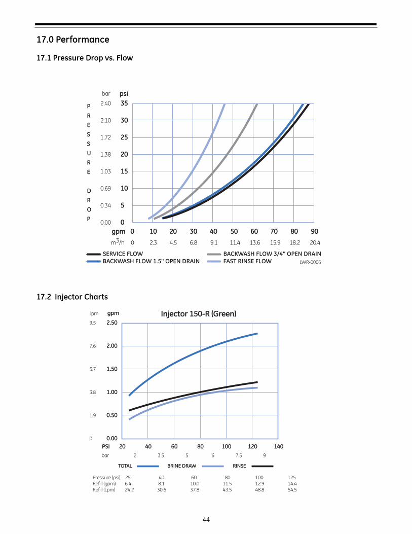
44
17.0 Performance
17.1 Pressure Drop vs. Flow
17.2 Injector Charts
P
R
E
S
S
U
R
E
D
R
O
P
SERVICE FLOW
10 3020 40 50 60 70 80 900
m3/h
gpm
4.5 6.8 9.12.30 11.4 13.6 15.9 18.2 20.4
2.40
2.10
1.72
1.38
1.03
0.69
0.34
0.00
bar psi
35
30
25
20
15
10
5
0
BACKWASH FLOW 1.5'' OPEN DRAINBACKWASH FLOW 3/4'' OPEN DRAINFAST RINSE FLOW LWR-0006
lpm gpm Injector 150-R (Green)2.50
2.00
1.50
1.00
0.50
0.00
bar
PSI 20
2 3.5 5 6 7.5 9
40 60 80 100 120 140
TOTAL BRINE DRAW RINSE
9.5
7.6
5.7
3.8
1.9
0
Pressure (psi) 25 40 60 80 100 125Refill (gpm) 6.4 8.1 10.0 11.5 12.9 14.4Refill (Lpm) 24.2 30.6 37.8 43.5 48.8 54.5
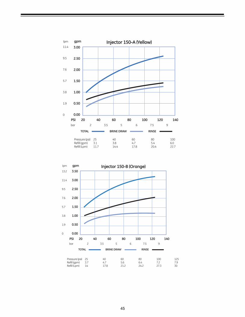
45
lpm gpm
3.00
2.50
2.00
1.50
1.00
0.50
0.00
bar
PSI 20
2 3.5 5 6 7.5 9
40 60 80 100 120 140
TOTAL BRINE DRAW RINSE
11.4
9.5
7.6
5.7
3.8
1.9
0
Injector 150-A (Yellow)
Pressure (psi) 25 40 60 80 100 Refill (gpm) 3.1 3.8 4.7 5.4 6.0 Refill (Lpm) 11.7 14.4 17.8 20.4 22.7
13.2
11.4
9.5
7.6
5.7
3.8
1.9
0
lpm gpm
3.50
3.00
2.50
2.00
1.50
1.00
0.50
0.00
bar
PSI 20
2 3.5 5 6 7.5 9
40 60 80 100 120 140
TOTAL BRINE DRAW RINSE
Injector 150-B (Orange)
Pressure (psi) 25 40 60 80 100 125Refill (gpm) 3.7 4.7 5.6 6.4 7.2 7.9 Refill (Lpm) 14 17.8 21.2 24.2 27.3 30
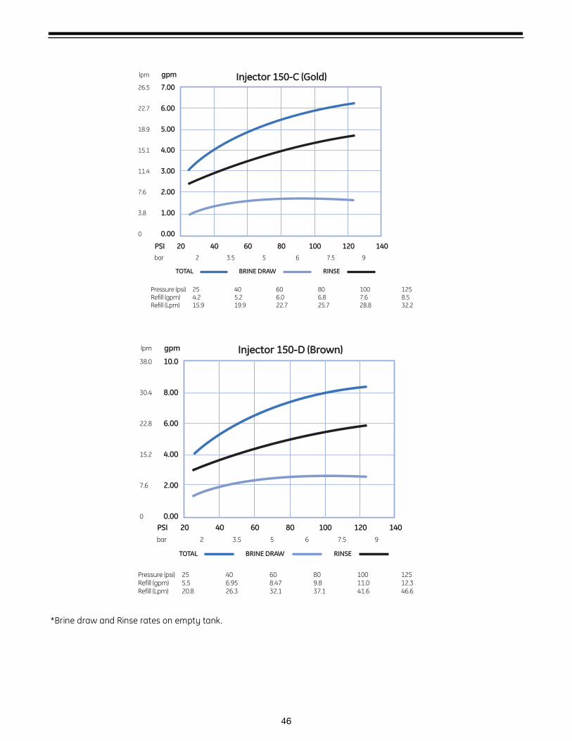
46
*Brine draw and Rinse rates on empty tank.
bar
PSI 20
2 3.5 5 6 7.5 9
40 60 80 100 120 140
TOTAL BRINE DRAW RINSE
26.5
22.7
18.9
15.1
11.4
7.6
3.8
0
lpm gpm
7.00
6.00
5.00
4.00
3.00
2.00
1.00
0.00
Injector 150-C (Gold)
Pressure (psi) 25 40 60 80 100 125Refill (gpm) 4.2 5.2 6.0 6.8 7.6 8.5 Refill (Lpm) 15.9 19.9 22.7 25.7 28.8 32.2
bar
PSI 20
2 3.5 5 6 7.5 9
40 60 80 100 120 140
TOTAL BRINE DRAW RINSE
38.0
30.4
22.8
15.2
7.6
0
lpm gpm
10.0
8.00
6.00
4.00
2.00
0.00
Injector 150-D (Brown)
Pressure (psi) 25 40 60 80 100 125Refill (gpm) 5.5 6.95 8.47 9.8 11.0 12.3Refill (Lpm) 20.8 26.3 32.1 37.1 41.6 46.6
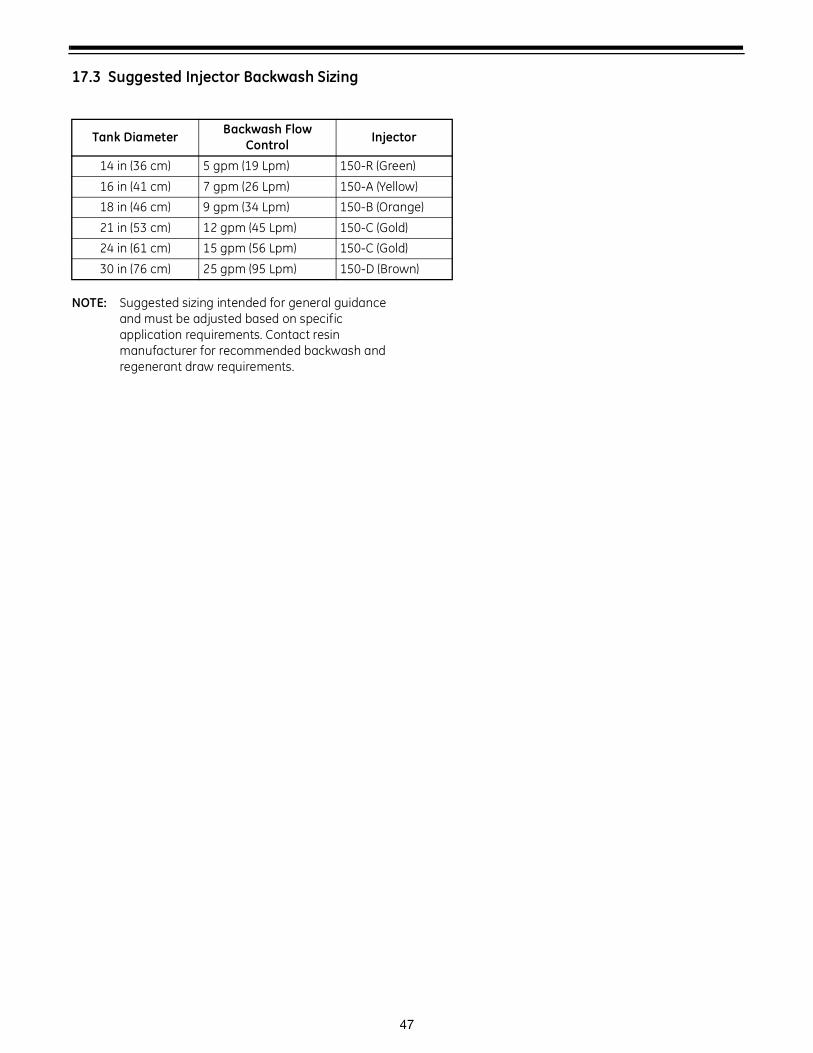
47
17.3 Suggested Injector Backwash Sizing
NOTE: Suggested sizing intended for general guidance and must be adjusted based on specific application requirements. Contact resin manufacturer for recommended backwash and regenerant draw requirements.
Tank Diameter Backwash Flow Control Injector
14 in (36 cm) 5 gpm (19 Lpm) 150-R (Green)
16 in (41 cm) 7 gpm (26 Lpm) 150-A (Yellow)
18 in (46 cm) 9 gpm (34 Lpm) 150-B (Orange)
21 in (53 cm) 12 gpm (45 Lpm) 150-C (Gold)
24 in (61 cm) 15 gpm (56 Lpm) 150-C (Gold)
30 in (76 cm) 25 gpm (95 Lpm) 150-D (Brown)
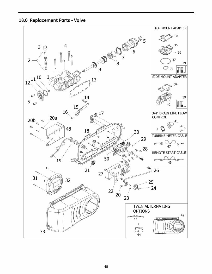
48
18.0 Replacement Parts - Valve
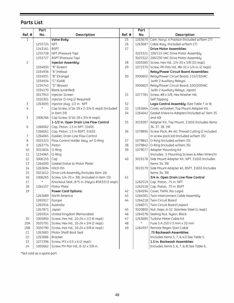
49
Parts List
*Not sold as a spare part
Ref. #PartNo. Description Ref. #
PartNo. Description
1 Valve Body: 25 1263670 Cam, Noryl, 4 Position (Included w/Item 27)1255724 NPT 26 1263687 Cable Assy. (Included w/Item 27)1243161 BSPT 27 Drive Motor Assemblies:1255728 NPT (Pressure Tap) 3025321 100/115 VAC Drive Motor Assembly1255727 BSPT (Pressure Tap) 3025322 200/230 VAC Drive Motor Assembly
2 Injector Assembly: 28 1005585 Screw, Hex Hd., 1/4-20 x 3/8 (10 reqd.)1034930 “R” (Green) 29 1072370 Screw, PH Pan Hd., #6-32 x 1/4 in. (2 reqd.)1034936 “A” (Yellow) Relay/Power Circuit Board Assemblies:1034931 “B” (Orange) 30 3000602 Relay/Power Circuit Board, 115/230VAC1034934 “C” (Gold) (with 2 Auxiliary Relays)1234743 “D” (Brown) 3000603 Relay/Power Circuit Board, 100/200VAC1034170 Blank (undrilled) (with 2 Auxiliary Relays, Japan)3017953 Injector Screen 31 1077781 Screw, #8 x 5/8, Hex Washer Hd, 1010301 Injector O-ring (2 Required) Self Tapping
3 1263693 Injector plug, 1/2 in. NPT 32 Logix Control Assembly: (See Table 7 or 8) 4 * Cap Screw, 5/16-18 x 2-3/4 (5 reqd.) (Included 33 1263664 Cover, w/Gasket, Top Mount Adapter Kit
in Item 39) 34 1264042 Gasket (Valve to Adapter) (Included w/ item 35 5 1006266 Cap Screw, 5/16-18 x 3/4 (4 reqd.) and 40)
1-1/2 in. Open Drain Line Flow Control 35 3019287 Adapter Kit , Top Mount, 316SS (Includes Items 6 1266062 Cap, Piston, 1.5 in NPT, 316SS 36. 37. 38. 39)
1266061 Cap, Piston, 1.5 in BSPT, 316SS 36 1078894 Screw Pack, #4-40, Thread Cutting (2 included 7 1264065 Gasket, Drain Line Flow Control in screw pack kit) (Included w/Item 35)8 3025323 Flow Control Holder Assy. w/ O-Ring 37 1079843 O-Ring (Included w/item 35)9 1263774 Piston 38 1079842 O-Ring (Included w/item 35)
10 3015834 O-Ring 39 1079077 Adapter Mounting Kit11 1234965 O-Ring (Includes: 5 Mounting Screws & Allen Wrench)12 3006155 Cap 40 3019178 Side Mount Adapter Kit , NPT, 316SS (Includes 13 1264000 Gasket (Valve to Motor Plate) Items 34, 39)14 1263694 Hitch Pin 3019179 Side Mount Adapter kit , BSPT, 316SS (Includes 15 3021612 Drive Link Assembly (Includes Item 16) Items 34, 39)16 1006265 Screw, 1/4-20 x .38L (Included in Item 15) 41 3/4 in. Open Drain Line Flow Control 17 * Knockout Seal, .875 in. (Heyco #3833) (3 reqd.) 1262519 Cap, Piston, .75 in. NPT18 1264157 Motor Plate 1262518 Cap, Piston, .75 in. BSPT19 Power Cord Options: 42 1264594 Cover, TWIN, (No Logix)
1263689 North America 43 1264581 Twin Interconnect Cable Assembly1265917 Europe 44 1264218 Twin Circuit Board1265916 Australia 1266071 Twin Circuit Board (Japan)1267871 Japan 45 3020800 Nut, Keps, 6-32, Stainless Steel (1 reqd.)1265914 United Kingdom (Removable) 46 1264578 Sealing Nut, Nylon, Black
20 1005850 Screw, Hex Hd., 10-24 x 1/2 (6 reqd.) 47 1263685 Turbine Meter Cable Kit20A 3020791 Screw, Hex Hd., 10-24 x 3/4 (2 reqd.) 48 * Fuse 5 A 250 V 5 mm x 20 mm20B 3020790 Screw, Hex Hd., 10-24 x 5/8 (4 reqd.) 49 1264597 Remote Regen Start Cable21 1263683 Motor Shaft Boot Seal .75 Backwash Assemblies:22 1263686 Bracket (Includes Items 5, 7, & 41) See Table 5.23 1072396 Screw, M3 x 0.5 x 6 (2 reqd.) 1.5 in. Backwash Assemblies:24 1005662 Screw, PH Pan Hd., 8-32 x 3/8 in. (Includes Items 5, 6, 7, & 8) See Table 6.
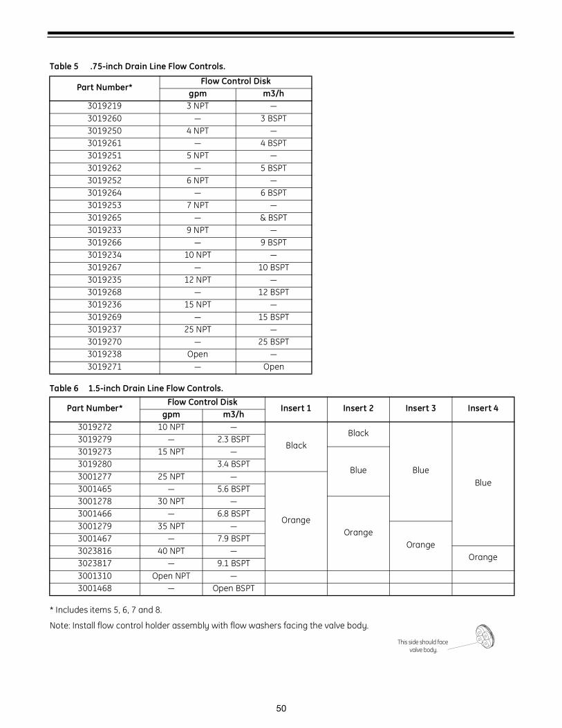
50
Table 6 1.5-inch Drain Line Flow Controls.
* Includes items 5, 6, 7 and 8.
Note: Install flow control holder assembly with flow washers facing the valve body.
Table 5 .75-inch Drain Line Flow Controls.
Part Number*Flow Control Disk
gpm m3/h3019219 3 NPT —3019260 — 3 BSPT3019250 4 NPT —3019261 — 4 BSPT3019251 5 NPT —3019262 — 5 BSPT3019252 6 NPT —3019264 — 6 BSPT3019253 7 NPT —3019265 — & BSPT3019233 9 NPT —3019266 — 9 BSPT3019234 10 NPT —3019267 — 10 BSPT3019235 12 NPT —3019268 — 12 BSPT3019236 15 NPT —3019269 — 15 BSPT3019237 25 NPT —3019270 — 25 BSPT3019238 Open —3019271 — Open
Part Number*Flow Control Disk
Insert 1 Insert 2 Insert 3 Insert 4gpm m3/h
3019272 10 NPT —
BlackBlack
BlueBlue
3019279 — 2.3 BSPT3019273 15 NPT —
Blue3019280 3.4 BSPT3001277 25 NPT —
Orange
3001465 — 5.6 BSPT3001278 30 NPT —
Orange
3001466 — 6.8 BSPT3001279 35 NPT —
Orange3001467 — 7.9 BSPT3023816 40 NPT —
Orange3023817 — 9.1 BSPT3001310 Open NPT —3001468 — Open BSPT
This side should face valve body.
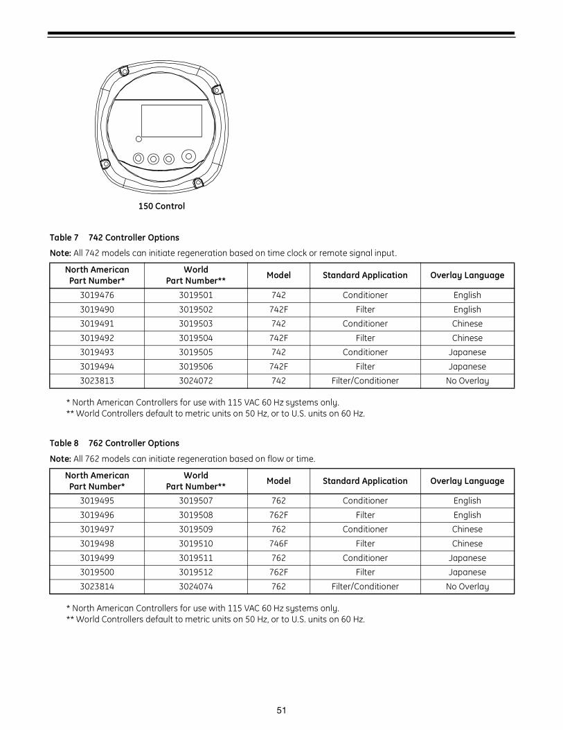
51
150 Control
* North American Controllers for use with 115 VAC 60 Hz systems only.** World Controllers default to metric units on 50 Hz, or to U.S. units on 60 Hz.
* North American Controllers for use with 115 VAC 60 Hz systems only.** World Controllers default to metric units on 50 Hz, or to U.S. units on 60 Hz.
Table 7 742 Controller Options
Note: All 742 models can initiate regeneration based on time clock or remote signal input.
North American Part Number*
World Part Number** Model Standard Application Overlay Language
3019476 3019501 742 Conditioner English
3019490 3019502 742F Filter English
3019491 3019503 742 Conditioner Chinese
3019492 3019504 742F Filter Chinese
3019493 3019505 742 Conditioner Japanese
3019494 3019506 742F Filter Japanese
3023813 3024072 742 Filter/Conditioner No Overlay
Table 8 762 Controller Options
Note: All 762 models can initiate regeneration based on flow or time.
North American Part Number*
World Part Number** Model Standard Application Overlay Language
3019495 3019507 762 Conditioner English
3019496 3019508 762F Filter English
3019497 3019509 762 Conditioner Chinese
3019498 3019510 746F Filter Chinese
3019499 3019511 762 Conditioner Japanese
3019500 3019512 762F Filter Japanese
3023814 3024074 762 Filter/Conditioner No Overlay

52
Service Shut-off Kit
Table 9 Service Shut-off Kits
Part Number Valve Model Valve Material Solenoid Connections
3019947 K52 Composite 120 V 1-1/2" male NPT
3019949 K52 Composite 220 V 1-1/2" female socket weld
3019956 V46 316 Stainless Steel 120 V 1-1/2" female NPT
3019957 V46 316 Stainless Steel 220 V 1-1/2" female BSPT

53

54

55

© Copyright 2007 General Electric CompanyPrinted in USA P/N 1266223 Rev E