
Serie costruttiva/Serie KRTpenelly.com/images/stories/amarex/Amarex-KRT-operating-instructio… ·...
80
KRT DN 200 bis DN 600 G deutsch english italiano Anhang français español Appendix Annexe Appendice Apéndice .../U .../X .../W 2104 ... 2804 1386 ... 3206 1268 ... 2808 K 10710 ... 27010 Amarex KRT 2553.807 -10 Betriebsvorschrift/ Operating Instructions/ Notice de service/ Prescrizioni di montaggio e di manutenzione/ Instrucciones de Servicio Tauchmotorpumpe/Submersible motor pumps/Pompes à moteur immergé/ Elettropompe sommerse/Motobombas sumergibles Baureihe/Series/Série/ Serie costruttiva/Serie Baugröße/type size/taille/ Grandezza/Tamaño Motorgröße/Motor size/Grandeur du moteur/ Grandezza del motore/Tamaño del motor Werkstoffausführung/Material types/ Matériau/Esecuzione materiali/ Ejecución de material Laufradformen Impeller types Formes de roues Tipi di giranti Tipos de rodete Motorversion Motor version Version du moteur Versione del motore Tipo de motor Werk-Nr.: siehe Fabrikschild Works No.: See data plate NØ de construction: voir plaque signalétique Nr. di matricola: vedi targhetta di fabbrica N o de fabricación Véase placa de caracteristicas Ident-No: 01064883
Transcript of Serie costruttiva/Serie KRTpenelly.com/images/stories/amarex/Amarex-KRT-operating-instructio… ·...
KRT
DN 200bis
DN 600
G
deutsch
english
italiano
Anhang
français
español
Appendix
AnnexeAppendice
Apéndice
.../U
.../X
.../W
2104 ... 28041386 ... 32061268 ... 2808
K
10710 ... 27010
Amarex KRT2553.807 -10
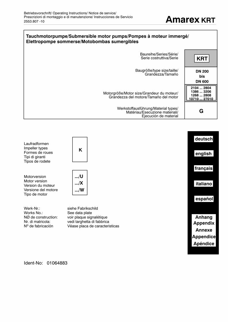
Betriebsvorschrift/ Operating Instructions/ Notice de service/Prescrizioni di montaggio e di manutenzione/ Instrucciones de Servicio
Tauchmotorpumpe/Submersible motor pumps/Pompes à moteur immergé/Elettropompe sommerse/Motobombas sumergibles
Baureihe/Series/Série/Serie costruttiva/Serie
Baugröße/type size/taille/Grandezza/Tamaño
Motorgröße/Motor size/Grandeur du moteur/Grandezza del motore/Tamaño del motor
Werkstoffausführung/Material types/Matériau/Esecuzione materiali/
Ejecución de material
LaufradformenImpeller typesFormes de rouesTipi di girantiTipos de rodete
MotorversionMotor versionVersion du moteurVersione del motoreTipo de motor
Werk-Nr.: siehe FabrikschildWorks No.: See data plateNØ de construction: voir plaque signalétiqueNr. di matricola: vedi targhetta di fabbricaNo de fabricación Véase placa de caracteristicas
Ident-No: 01064883

Amarex KRT
2
ContentsPage
1. General 3
2. Safety 32.1 Identification of symbols used within the 3
operating manual2.2 Personnel skills and training 32.3 Dangerous practices -- non-observation of 3
safety instructions2.4 Safe working methods 32.5 Safety instructions for the operators 32.6 Safety instructions during maintenance, 4
inspection and installation2.7 Unauthorised modifications to the pump and 4
fitting of replacement parts2.8 Unacceptable operating methods 4
3. Transport and storage 43.1 Safety measures 43.2 Transport 43.3 Storage/conservation 4
4. Description of pump 44.1 General description 44.2 Identification data 44.3 Construction 54.4 Ancillary equipment 54.5 Dimensions 5
5. Assembly/Installation 65.1 Safety regulations (flame-proof) 65.2 Checking procedure prior to commencement 6
of installation5.3 Installation 65.4 Electrical connection 65.5 Direction of rotation 75.6 Assembly kit installation 8
6. Start-up / Shutdown 116.1 Initial start up of pump 116.2 Limitations of operating range 116.3 Shut down/storage/conservation 126.4 Re-starting pump after storage 12
7. Service and maintenance 127.1 General instructions 127.2 Service/Inspection 127.3 Dismantling and re-assembly 157.4 Re-assembly 167.5 Maintaining stock level of replacement parts 177.6 Table ”Lubricating instructions” 18
8 Faults 19
9. Annexe 20
Attention
Amarex KRT
3
1 GeneralKSBpumps aremanufacturedwith great care and are subjectto continuous quality control. If the pumps are correctly in-stalled and serviced we guarantee problem-free operation.This unit must be operated in strict compliance with the in-structions printed on the data plate relating to quantity, speedof rotation, pressure and temperature, and in linewith anyoth-er instructions outlined in the operating instructions or the or-der documentation. All instructions relating to electrical val-ues, installation and servicing must be strictly observed.Non-compliancewith these conditions during operation of theplant will lead to overloadingwhich could lead to pump failure.
The Discription and instructions within this operating manualrelate to standard design pumps and variants.If you cannot find all the information and instructions required,then contact the nearest KSB service agent.The data plate attached to the pump, Appendix 1 ”Generalpump outline” Fig. 1, gives the series/size, the most impor-tant operating data and works number/identity number, whichmust always be quoted when making enquiries, placing sub-sequent orders and especially when ordering replacementparts.In the case of damage please contact the nearest KSBservice agent or the manufacturing company.
2. SafetyThisoperatingmanualcontainsbasic instructions,whichmustbe observed during installation, operation and servicing.Therefore it is imperative that this manual is read prior to as-sembly by the fitter and relevant skilled staff/and operatorsand it must always be kept within the locality of the machine/plant.With regard to safety, not only those instructions listed underthemainheadingof safetymust beobserved, butalsoall otherspecial safety instructions which have been included underany othermain headingmust be strictly adhered to, for exam-ple for pumps privately owned.
2.1 Identification of symbols used within theoperating manual
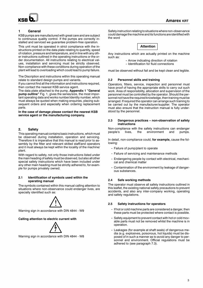
The symbols contained within this manual calling attention tosituations where non-observance could endanger lives, arespecially identified such as:
Warning sign in accordance with DIN 4844 - W9
Calling attention to electric current with
Warning sign in accordance with DIN 4844 - W8
Safety instructionrelating tosituationswherenon-observancecoulddamage themachineand its functionsare identifiedwiththe word
Any instructions which are actually printed on the machinesuch as:
-- Arrow indicating direction of rotation-- Identification for fluid connections
must be observed without fail and be kept clean and legible.
2.2 Personnel skills and trainingOperators, fitters, service, inspection and personnel musthave proof of having the appropriate skills to carry out suchwork. Area of responsibility, allocation and supervision of thepersonnel must be controlled by the operator. Should the per-sonnelnothave the requiredknowledge, then trainingmustbearranged. If required the operator can arrange such training tobe carried out by the manufacturer/supplier. The operatormust also ensure that the instruction manual is fully under-stood by the personnel.
2.3 Dangerous practices -- non-observation of safetyinstructions
Non-compliance with the safety instructions can endangerpeople‘s lives, the environment and pumps.
In detail, non-compliance could, for example, cause the fol-lowing:
-- Failure of pump/plant to operate
-- Failure of servicing and maintenance methods
-- Endangering people by contact with electrical, mechani-cal and chemical matter
-- Contamination of the environment by leakage of danger-ous substances.
2.4 Safe working methodsThe operator must observe all safety instructions outlined inthis leaflet, the existing national safety precautions to preventaccidents, and also any inter-company working, operatingand safety regulations.
2.5 Safety instructions for operators
-- If hot or coldmachine parts are considered a danger, thenthese parts must be protected where contact is possible.
-- Safety equipment to prevent contactwith hot or coldmov-able parts must not be removed whilst the machine is inoperation.
-- Leakages (for example at shaft seals) of dangerous me-dia (e.g. explosives, poisonous, hot liquids) must be dis-posed of in such a manner as to avoid any danger to per-sonnel and environment. Official regulations must beadhered to (see paragraph 7.3).
!
Amarex KRT
4
-- Danger causedby electric supplymust be eliminated (inthis respect see details of any regulations enforced byindividual countries of the VDE and/or the local powersupply stations.
2.6 Safety instructions during maintenance,inspection and installation
The operator carries the responsibility to ensure that all ser-vice, inspection and maintenance work is carried out byauthorised and fully trained personnel,whohave readandarefamiliar with the operating instructions.Basically all work to the plant should only be carried out whenthemachine is not operating. The operating instructions relat-ing to the method of switching off the equipment must be ad-hered to without fail.Pumps or plant pumping dangerous media must be decon-taminated.Once maintenance work is completed all safety equipmentmust be reinstated again and checked to ensure they functioncorrectly.Read and follow the point listed in the paragraph ”initial/firstcommissioning” prior to installation.
2.7 Unauthorised modifications to the pump andfitting of replacement parts
Modifications to thepumpcanonlybecarriedout afterauthori-sation has been obtained from the manufacturer. Original re-placementpartsandancillaryequipmentsuppliedby theman-ufacturer provide safety. Installation of any other equipmentcancels the guarantee for any pump failure which occurs asa result of installing non-manufacturer‘s parts.
2.8 Unacceptable operating methodsOperating safety of the equipment is only guaranteed if all op-erating instructions as outlined in paragraph1 -- General -- areobserved. The limits given in the data sheetmust under no cir-cumstances be exceeded.
3. Transport and storage
3.1 Safety measures
The chain or liftingwirewhich is suppliedmust onlybe used for lifting the appropriate pump unit. Gen-eral use for lifting heavy loads is not permitted.
Do not lift the pump unit by the motor cable.
3.2 Transport
The motor housing/cover of the pump has been prepared forattaching the chain supplied with the unit. For lifting the unitduring unpacking only this prepared fixing should be used forattaching the lifting chain. Furthermore, attention is drawn tothe fact that the design of this fixing point on themotor housingvariesaccording tomethodof installation -- whether stationaryor transportable.Appendix 1: General pump outlineFig. 2a for stationary wet installationFig. 2b for transportable installation
Further details for fitting of chain/lifting wire are outlined in thedescription ”Assembly kit stationary and transportable” --please refer to:5.6.2.5 Fitting of chain/lifting wire stationary wet well
installation5.6.3.4 Fitting of chain/lifting wire transportable installation5.6.4.3 Fitting of claw/duckfoot bend/guide hoop
3.3 Storage/conservationTheprocedure has beenoutlined in the paragraph ”Taking outof operation” item 6.3.
4 Description of pump4.1 General description
KRTsubmersiblepumpsaresubmersible, singlestage,singleentry, close coupled pump sets in flameproof or non-flame-proof design. They are available with free-flow impellers (F),single vane impellers (E) and non-clogging impellers (K) andthe KRT 40-160 is available with a cutter.
4.2 Identification data
The identificationcanbe foundon thedataplate,which is fittedto the motor. Illustration data plate for non-flameproof and fla-meproof design see appendix 1: ”General pump outline”Fig 1.
!
Discharge nozzleInternal diameter
SeriesImpeller type (E,F,K,S)
Hydraulicsize
Motor power in kW (relating to U)
Impeller diameter in mm
KRT F 100--320 / 24 4 X 1 G -- 295
Numberof Poles
Motor version (U, W, X, Y)
Generation identity No.
E= single vane impellerF= free-flow impellerK= non-clogging impellerS= with cutter
Max impellerdiameter in mm
U = non-flameproofW = Hot water design
(max. 60O C)X = Flameproof T3Y = Flameproof T4
G = Pump complete in cast ironG1 = Cast iron pump with stainless steel impellerG2 = Cast iron pump with Norihard impellerGH/H = Norihard designC1/C2= stainless steel design
2--pole.4--pole.6--pole.8--pole.10--pole.
Material types/variants(G, G1, G2, GH/H, C1/C2)
Motor size

Amarex KRT
5
4.3 Construction
4.3.1 DriverThree-phase asynchronous motor with connecting cable.Winding to IEC 38 standard 400 V voltage rating, special volt-ages in compliance with data plate. Protection IP 68 in accor-dance with DIN 40050/IEC 528, Motor design to VDE 0530Part 1/IEG34-1 insulationmaterial class Fand additionally forflameproof equipment VDE 0171/5.78 part 1 and part 5/EN 50014/EN 50018, ignition protection EEx dIIB T3 or T4.
Starting method standard: up to 4 kW direct, > 4 kW Autotransformer or star/delta.
4.3.2 Shaft seal
The shaft seal consists of two independent elastomer bellowsmechanical seals which are independent of rotation and ar-ranged in tandem. Size KRT 40-160 and KRT 65-200 man-ufactured inmaterial codeG,are fittedwitha lip seal at themo-tor end. The oil chamber between the seals ensures coolingand lubrication. It is filled with environmentally friendly non--toxic paraffin oil.
4.3.3 Bearing assembly
up to motor size...624/,...646,/...548
grease lubricated, maintenancefree ball bearing
from motor size784,.../806,.../678,.../4310,...
grease lubricated ball bearing,which can be re-lubricated withoutdismantling pump unit
4.3.4 Impeller types
Cutter (S) for faeces, domestic sewageand sewage containing long fibrousmixtures
Free-flow impeller (F-impeller) for pump-ing liquids containing larger solid par-ticles and fibres liable to twist and bunchand also gas and air inclusions
Single vane impeller (E-impeller) forpumping liquids containing larger solidparticles and fibres liable to twist andbunch, and also for the damage-freetransport of solids
Closed non-clogging impeller (K-impel-ler) for contaminated non-gaseous liq-uids containing solids, without fibres li-able to twist and bunch.
4.3.5 Pump casing
The pump casing is fitted with radial outlet branch and stan-dard flange-connection.Use of appropriate assembly kit will permit either stationary ortransportable installation of the pump unit.
4.3.6 Installation methodsSubmersible pumps can be installed at low cost.The following installation methods can be used:
-- stationary wet installation guide wire-- transportable installation-- stationary wet assembly hoop (only KRT 40-160)
Detailed installation description see item 5.6.
4.4 Ancillary equipment
KSBswitchgear isavailable toensure trouble-free functioningof the unit and the monitoring equipment. Recommendedequipment is described in Appendix 6 ”Electricalconnection diagram”
For expert installation of the electrical connections within thepump sump we can supply suitable cable socks.
Any information relating to other ancillary equipment will begiven by our Sales Office.
4.5 Dimensions
Information regarding dimensions andweight can be found inAppendix 4 ”Dimensions Table”.

Attention
Attention
Attention
Amarex KRT
6
5. Assembly/Installation
5.1 Safety regulations (flameproof)
Equipment to be installed in explosion dangerareas within Zone 1, must fulfil the fire protectionregulations.Details can be foundon the dataplate.When installing the equipment in explosion dan-
ger-areas within Zone 1, then the fire precautions and regula-tions set out in the PTB-test certificate have to be observedand adhered to. The PTB-test certificate must be kept withinthe location of operation (Foreman‘s Office).
5.2 Checking procedure prior to commencement ofinstallation
Construction lay-out must be in accordance with measure-ments set out on the table of dimensions.The construction of the base/concrete foundations should besufficiently strong (Min. BN 150) to ensure secure and func-tionally correct installation in compliance with DIN 1045 orequivalent standard can take place.
5.3 InstallationIt is imperative prior to installation of thepumps to check paragraph 5.3.1 of the
operatingdata,paragraph5.3.2 -- oil level control andalsoparagraph 5.5 -- direction of rotation.
Included in the items delivered there is a separate data plate,attached to the cable end, which gives the pump and motordata. This data plate must be fixed in a clearly visible positionoutside thesump (for example switchpanel, pipework,mount-ing bracket).
5.3.1 Checking of operating data
A check must be carried out to ensure that the details statedon the data plate agree with the order and pump data (for ex-ample operating voltage, frequency and pumped media tem-perature etc.).
5.3.2 Oil level control
The oil chambers of our submersible pumps have been filledwith environmentally friendly non-toxic paraffin oil of medicalstandard quality.The oil level must be checked prior to initial operation ofthe unit.
Procedure
Position the pump in accordance with ”General pump dia-gram” appendix 1, Fig. 3. Unscrew the plug 903.02 and gas-ket 411.03. The minimum oil level must not exceed ”M”.Should the oil level be lower then fill the oil chamber via thetapped hole until it overruns. See paragraph 7.2.5 for oil quali-ty and quantity. (Oil change)Tighten the plug with gasket.
5.4 Electrical connection
5.4.1 General
The electrical connection must be carried out by atrainedelectricianand in compliancewith local reg-ulations. Recommendation VDE 0100 and for fla-meproof equipment VDE 0165.The voltage must comply with the voltage indi-cated on the data plate.
Electrical installationmust be in accordancewith paragraph 9”Electrical installation lay-out” and ”performancelay-out” for the appropriate motor sizes.
The pump is delivered completely assembled with andincluding cable diameters 4x35 mm2. From cable diameter4x50 mm2 onwards electrical cables are supplied loose fortransport reasons, and they have to be installed prior to as-sembly as outlined in Appendix 2.1 ”General drawing ofcable connections” and Appendix 8 installation instruc-tions ”Cable entry”.
The protection cover which is situated atthe cable gland, should not be removeduntil immediately before installation.
The individual coresof the cableare identifiedby yellow identi-ty tags and black writing (for example U.V.W 21,22 or10,11,...).Should it be necessary to shorten the cable, then the printedcore numbers i.e. the core colours should be used as a guide.In such cases the yellow tags should be removed and thencorrectly re-attached to the shortened cores.
When laying an earth cable between thepumping station and the electrical switch
gear, then additional multi-core control cable (min. 1,5 mm2)must be installed for motor monitoring equipment and floatswitch control.Adjust cores to suit requirement.
When draining low lying equipment a non-return valve shouldbe fitted into the outlet pipe to avoid liquid being returned fromthe channel.
Within the flameproof area all electrical cablingmust be connected to earth with flameproof termi-nal boxes or approved cast resin sockets (in accor-dance with VDE 0165).
5.4.2 Electrical connection
5.4.2.1Monitoring equipment
The unit has been supplied with monitoring equipment to pre-vent overloading. Installation, description and functioning ofthemonitoring equipment can be taken fromAppendix 6 andAppendix 7.1 to 7.4 ”Electrical connections diagrams/cir-cuit diagrams temperature control”.
Attention
Attention
Attention
Amarex KRT
7
5.4.2.2Power connections
When the equipment is installed in explosion-danger areas,then provision has to be made for a potential equaliser. Thepotential equaliser conductor is connected to the terminalPartNo. 81-29.03 or support (yoke) part No. 81-11.01, 900.24,932.24 (Appendix 1 ”General pump outline” Fig. 4) whichis situated at the cable entry i.e. at the terminal box.
Special requirements for chemically corrosive corrosivemedia.
When the unit is used for chemically corrosive corrosive me-dia and with a flameproof pump then the connecting clampwhich is situated outside the unit must not be used.
Instead the potential equaliser should be fitted to a flange atthe outlet pipewhich does not come in contact with themedia.Please ensure that there is an electrical connection betweenthe newly created potential equaliser and the pump.
Procedure(Appendix 1 ”General pump outline” Fig. 5)1. Drill a hole diameter size 8,8 + 0,1 mm on the flange at the
outlet pipe which is not subject to pumped media admis-sion.
2. The end terminal 81-29 supplied should be dismantled andforced into the drilled hole using the tool provided.
3. Install earth terminal and connect potential equaliserconductor.
5.4.2.3Installation for frequency inverter operation
The given motor capacity of P2 can only be used up to 85%.With flameproof equipment a thermistor relay unit with resetfacility and PTB-certificate must be installed. (for exampleMessrs. SiemensType3UN6with reset facility).Other specialcharacteristics for this method of operation can be taken fromAppendix 6 and Appendix 7.1 to 7.4 ”Electrical connec-tions diagram/circuit diagram.
5.4.3 Fitting of electric cabling
During installation of the electric cabling it isadvised to position the motor supply cable
upwards and if possible fastened it to avoid it being affectedby the swirl created by the pumped liquid.
For correct installation of the electric cabling within thepumpsump (Appendix1 ”Generalpumpoutline”Fig. 5)werecommend using cable socks, which can be supplied as anadditional extra (paragraph 4.4). Slack installation of cablescould cause damage to the electric cabling during vibrationwhen the pump is operating.
5.4.4 Fitting cable protection sockIf the electrical connection cable is supplied inclusive of a sus-pension sock, then this must be installed prior to assembly incompliance with the operating instructions for ancillary equip-ment ”Suspension sock installation”.
5.4.5 Overcurrent relayThe motor has to be protected against overloading by a ther-mally retarded over-current relay to comply with VDE 0660.This should be adjusted to the nominal motor current as indi-cated on the data plate on the motor. The regulating value forstar delta is IN x 0,58. However, this only applies when the
overload relay between star delta combination andmotor hasbeen switched on.
5.4.6 Level control switch
Stations with automatic pump operation should be fitted witha level control switch. Cut-off control print should be adjustedto comply with Appendix 4 ”Dimensions Table” this willcause the pump to stop and avoid possible dry running.
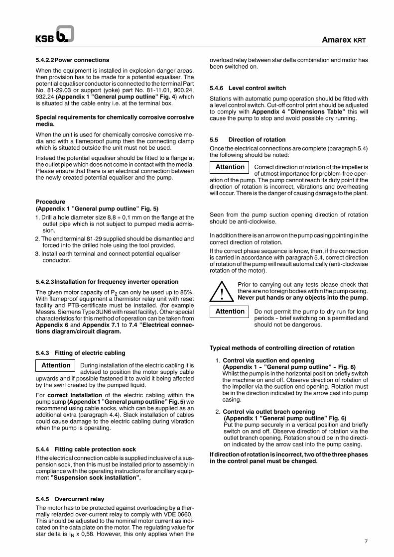
5.5 Direction of rotationOnce the electrical connections are complete (paragraph5.4)the following should be noted:
Correct direction of rotation of the impeller isof utmost importance for problem-free oper-
ation of the pump. The pump cannot reach its duty point if thedirection of rotation is incorrect, vibrations and overheatingwill occur. There is the danger of causing damage to the plant.
Seen from the pump suction opening direction of rotationshould be anti-clockwise.
In addition there is an arrowon thepumpcasingpointing in thecorrect direction of rotation.If the correct phase sequence is know, then, if the connectionis carried in accordance with paragraph 5.4, correct directionof rotation of thepumpwill result automatically (anti-clockwiserotation of the motor).
Prior to carrying out any tests please check thatthere are no foreign bodieswithin the pumpcasing.Never put hands or any objects into the pump.
Do not permit the pump to dry run for longperiods -- brief switching on is permitted andshould not be dangerous.
Typical methods of controlling direction of rotation
1. Control via suction end opening(Appendix 1 -- ”General pump outline” -- Fig. 6)Whilst the pump is in the horizontal position briefly switchthe machine on and off. Observe direction of rotation ofthe impeller via the suction end opening. Rotation mustbe in the direction indicated by the arrow cast into pumpcasing.
2. Control via outlet brach opening(Appendix 1 ”General pump outline” Fig. 6)Put the pump securely in a vertical position and brieflyswitch on and off. Observe direction of rotation via theoutlet branch opening. Rotation should be in the directi-on indicated by the arrow cast into the pump casing.
If directionof rotation is incorrect, twoof the threephasesin the control panel must be changed.
!
Amarex KRT
8
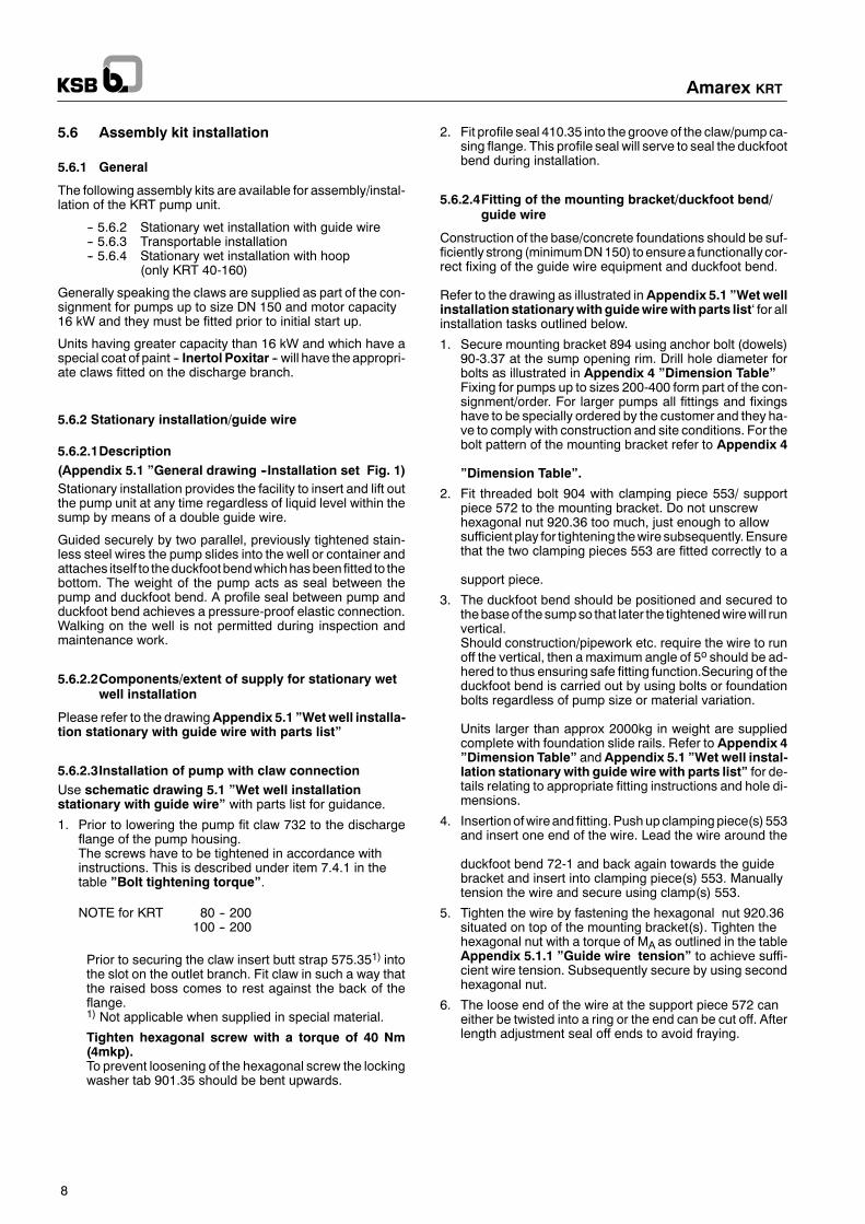
5.6 Assembly kit installation
5.6.1 General
The following assembly kits are available for assembly/instal-lation of the KRT pump unit.
-- 5.6.2 Stationary wet installation with guide wire-- 5.6.3 Transportable installation-- 5.6.4 Stationary wet installation with hoop
(only KRT 40-160)
Generally speaking the claws are supplied as part of the con-signment for pumps up to size DN 150 and motor capacity16 kW and they must be fitted prior to initial start up.
Units having greater capacity than 16 kW and which have aspecial coat of paint -- Inertol Poxitar -- will have the appropri-ate claws fitted on the discharge branch.
5.6.2 Stationary installation/guide wire
5.6.2.1Description(Appendix 5.1 ”General drawing --Installation set Fig. 1)Stationary installation provides the facility to insert and lift outthe pump unit at any time regardless of liquid level within thesump by means of a double guide wire.
Guided securely by two parallel, previously tightened stain-less steel wires the pump slides into the well or container andattaches itself to theduckfootbendwhichhasbeen fitted to thebottom. The weight of the pump acts as seal between thepump and duckfoot bend. A profile seal between pump andduckfoot bend achieves a pressure-proof elastic connection.Walking on the well is not permitted during inspection andmaintenance work.
5.6.2.2Components/extent of supply for stationary wetwell installation
Please refer to the drawingAppendix 5.1 ”Wetwell installa-tion stationary with guide wire with parts list”
5.6.2.3Installation of pump with claw connectionUse schematic drawing 5.1 ”Wet well installationstationary with guide wire” with parts list for guidance.
1. Prior to lowering the pump fit claw 732 to the dischargeflange of the pump housing.The screws have to be tightened in accordance withinstructions. This is described under item 7.4.1 in thetable ”Bolt tightening torque”.
NOTE for KRT 80 -- 200100 -- 200
Prior to securing the claw insert butt strap 575.351) intothe slot on the outlet branch. Fit claw in such a way thatthe raised boss comes to rest against the back of theflange.1) Not applicable when supplied in special material.
Tighten hexagonal screw with a torque of 40 Nm(4mkp).To prevent loosening of the hexagonal screw the lockingwasher tab 901.35 should be bent upwards.
2. Fit profile seal 410.35 into the groove of the claw/pumpca-sing flange. This profile seal will serve to seal the duckfootbend during installation.
5.6.2.4Fitting of the mounting bracket/duckfoot bend/guide wire
Construction of the base/concrete foundations should be suf-ficiently strong (minimumDN150) toensurea functionally cor-rect fixing of the guide wire equipment and duckfoot bend.
Refer to the drawing as illustrated inAppendix 5.1 ”Wetwellinstallationstationarywithguidewirewithparts list‘ for allinstallation tasks outlined below.
1. Secure mounting bracket 894 using anchor bolt (dowels)90-3.37 at the sump opening rim. Drill hole diameter forbolts as illustrated in Appendix 4 ”Dimension Table”Fixing for pumps up to sizes 200-400 form part of the con-signment/order. For larger pumps all fittings and fixingshave to be specially ordered by the customer and they ha-ve to comply with construction and site conditions. For thebolt pattern of the mounting bracket refer to Appendix 4
”Dimension Table”.
2. Fit threaded bolt 904 with clamping piece 553/ supportpiece 572 to the mounting bracket. Do not unscrewhexagonal nut 920.36 too much, just enough to allowsufficient play for tightening thewire subsequently.Ensurethat the two clamping pieces 553 are fitted correctly to a
support piece.
3. The duckfoot bend should be positioned and secured tothebaseof the sumpso that later the tightenedwirewill runvertical.Should construction/pipework etc. require the wire to runoff the vertical, then amaximum angle of 5o should be ad-hered to thus ensuring safe fitting function.Securing of theduckfoot bend is carried out by using bolts or foundationbolts regardless of pump size or material variation.
Units larger than approx 2000kg in weight are suppliedcomplete with foundation slide rails. Refer to Appendix 4”Dimension Table” andAppendix 5.1 ”Wet well instal-lation stationary with guide wire with parts list” for de-tails relating to appropriate fitting instructions and hole di-mensions.
4. Insertionofwireand fitting.Pushupclamping piece(s) 553and insert one end of the wire. Lead the wire around the
duckfoot bend 72-1 and back again towards the guidebracket and insert into clamping piece(s) 553. Manuallytension the wire and secure using clamp(s) 553.
5. Tighten the wire by fastening the hexagonal nut 920.36situated on top of the mounting bracket(s). Tighten thehexagonal nut with a torque of MA as outlined in the tableAppendix 5.1.1 ”Guide wire tension” to achieve suffi-cient wire tension. Subsequently secure by using secondhexagonal nut.
6. The loose end of the wire at the support piece 572 caneither be twisted into a ring or the end can be cut off. Afterlength adjustment seal off ends to avoid fraying.

Amarex KRT
9
7. Place shackle 59-18 into the mounting bracket 894 toenable the lifting chain to be attached at a later stage.
Table bolt tightening torque ”steel anchor bolt”
Size Torque (Nm)10 1012 2518 80
Table bolt tightening torque ”foundation bolt”
Size Torque (Nm)12 2516 6520 12524 21030 420
Table ”Guide wire -- tension”
Size MA(Nm)
P(N)
65-160 9 4 000
MA = Tightening torqueP = Wire tension
5.6.2.5Fitting of chain / lifting wire stationary wet wellinstallation
Installation of this equipment should be carried out in accor-dance with ”General pump outline” Fig. 2a by inserting thechain/liftingwire into the loop opposite the outlet branch. Furt-her details can be found in ”Wet well installation stationarywith guide wire with parts list”.
This type of fixing achieves a forward inclination of the pumptowards theoutlet branchandpermits fittingpump to theduck-foot bend.
5.6.2.6Installation of the pump(”General arrangement of installation parts” Fig. 1)Guide the pump from above over the support piece 572 andthread into the guide wire, then lower slowly.
After lowering the pump it will fasten itself to the duckfoot bend72-1 and it is then ready for operation and connected to theinlet pipe.
5.6.2.7Connection of the pipeline(”General arrangement of installation parts” Fig. 1)Thedischarge pipe should be connected to the duckfoot bendwithout stress (i.e. not putting any load onto the flange).To avoid backflow from the delivery main whilst draining thesump non--return valve must be fitted into the discharge pipe,which is taken over and above the back-flow level and onlythen led into the sewage channel.In addition it is necessary to fit non--return valve for longer ri-sing pipes, to avoid increased back-flow when the pump isswitched off. For ventilation reasons this non--return valveshould not be fitted immediately on the duckfoot bend. For fit-ting suggestions refer to the abovementioned appendix. If fit-ting on the duckfoot bend cannot be avoided, then drill a venti-lation hole into the duckfoot bend.

Amarex KRT
10
5.6.3 Transportable installation
5.6.3.1Description
Pumps for transportable installation are supplied with a pumpstand. The outlet branch with DIN connections lends itself forfitting either rigid or flexible piping.Examples for typical installation possibilities can be takenfrom Appendix 5 ”General arrangement of installationparts” Fig. 2.Ancillary equipment can be requested and purchased fromour sales offices.
5.6.3.2Components/extent of supply for transportableinstallation
For parts supplied and detailed illustration see Appendix 5.2”Wet well transportable installation with parts list”
5.6.3.3Assembly kit installation
Please refer todrawing inAppendix5.2 ”Wetwell transport-able installation with parts list” for assembly.
1. The base plate or the pump standmust be fitted prior to in-stalling the pump. All screwsmust be tightened accordingto instructions.Refer to table ”Bolt tightening torque” para-graph 7.4.1 for instructions.
Special characteristics for KRT 80--200100--200
The cast iron design has 4 cast-in slots on the suction cov-er of the pump. Pump legs 183 should be pushed into thecast slots one after another and fastened bymeans of caphead screws 914.15 and square-headed nuts 920.04.Attention!The outer fastening screw 914.16 has to be unscrewed in2 places in order to gain access (maintenance) to the caphead screws 914.15.
5.6.3.4Assembly chain/lifting wire/transportableinstallation
Fitting of chain/lifting wire should be carried out as outlined inAppendix 5.2 ”Wet well installation transportable withparts list”
For Pumps with a motor capacity of 4 kW always use the loopwhich is fitted on the discharge side, see Appendix 1”General pump outline” Fig. 2b.
5.6.3.5Installation of pump
Transportable installation permits the pumps to operate in dif-ferent locations.For example, they can be used for:
draining of minesemergency draining of canalspumping water out rivesr etc.
For such applications the pumpmust be installed in a verticalposition with the motor on the top and fitted to a firm base.
5.6.4 Stationary installation with hoop only forKRT 40-160
5.6.4.1Description(Appendix 5 ”General arrangement of installation parts”Fig. 3)
The installationmethodwith guide hoop is applicable for shal-low installation (approx 1,5 m)
The various types are:
-- Guide hoop with mounted duckfoot bend at the bottomof the sump
-- Guide hoop with suspended duckfoot bend
The hoop guide operates in the same way as the guide wireand makes lowering or lifting of the pump possible for exam-ple: when the sump is flooded.
5.6.4.2Components/extent of supply for hoop design
Please refer to Appendix 5.3 ”Wet well installation hoopwith parts list”which outlines parts supplied and gives a de-tailedillustration.
5.6.4.3Installation of claw/duckfoot bend/guide hoop
Please refer to drawingAppendix 5.3 ”Wet well installationhoop with parts list” and use as guide for installation. Thefirst step is to assemble the clawand chain/liftingwire as illus-trated in the above mentioned drawing.
-- Installation of guide hoop with mounted/fitted duck-foot bend
1. Fit hoop 571 into the duckfoot bend 72-1 in such a waythat the short ends are suspended/attached under thefeet on the pump side..
2. Screw duckfoot bend 72-1 using bolts 90-3.03 to thebase of the sump.
3. Provide fixing point for the chain at the side of the sump.
-- Installation of guide hoop with suspended duckfootbend
1. Install hoop 571 into the duckfoot bend 72-1 in such away that the short ends are inserted in the slots providedon the side of the sump. Secure yoke by using the dowelpins 561 supplied to prevent the hoopbeing pushedout.
2. Fasten support 183 with buffer 595 at duckfoot bend,and if necessary shorten on pump side.
3. Provide fixing point for the chain at the side of the sump.
5.6.4.4Installation of the pump
Guide thepump fromaboveover thehoop571and slowly low-er into the sump.After lowering the pump it will fasten/lock itself to the duckfootbend 72-1 and it is then connected to the inlet pipe and readyfor operation.

Attention
Attention
Amarex KRT
11
6 Start up/shut down
KRT submersible pumps are constructed to ensure long andtrouble·free operation under normal operating condition.To achieve this it is important to fulfil the following require-ments. Any damage incurred as a result of non-compliance isnot covered by the guarantee.
6.1 Initial start up of pump
Prior to starting the pump it has to be ascertained that the fol-lowing points have been checked and executed:
Operatingdataparagraph5.3.1,oil level paragraph5.3.2and direction of rotation paragraph 5.5must be checked.
-- Ensure that all electrical equipment including all safetyequipment have been connected in accordance with in-structions, and that they comply with ”Electrical con-nections diagram/circuit diagrams (see also para-graph 5.4)The winding temperature control can only function, if thetemperature circuit is installed in accordance with”Electrical connections diagram/circuit diagrams”.Flameproof equipment is only guaranteed when bothtemperature circuits have been connected.
-- Ensure that the pump has been installed correctly tocomply with installation kit paragraph 5.1/5.2.
-- Should the pumphavebeenout of service for a long peri-od, then the steps outlined in paragraph 6.3must be car-ried out.
6.2 Limitations of operating range
6.2.1 Minimum liquid level
The pump is ready for operation when the liquid level hasreached measuring mark ”R”.This minimum liquid level also applies for pumping stationswith automatic pump operation.l”General pump outline” Fig. 7)
”R” = Lowest switch off point for automatic operation
”M” = Minimum liquid level for constant operation
Built-in temperature controls within the winding will protectthe motor from overheating. If the motor overheats (for ex-ample during long operationwith a completely exposedmo-tor) then the built-in temperature controls will switch off themotor and turn it on again automatically after cooling down(see paragraph 5.4 electrical connections). Protectionagainst dry operation which causes the pump to be auto-matically switchedoff (cut-off contact)must carry a full guar-antee covering technical controls. (Paragraph 5.4.6)
Dry running leads to increasedwear andtear and should be avoided.
6.2.2 surroundings
KRT .... type X,Y flameproof 40 OCKRT .... type U non-flameproof 1) 40 OC or as indicated
on data plateKRT .... type W non-flameproof 1) 60 OC or as indicated
on data plate1) Can be operated up to 80oC for a limited period (3-5mins. or until
the thermal protection equipment is activated)
Do not operate the equipment at tempera-tures higher than those indicated above.
Only if the manufacturer has given written consent. Damagecaused due to non-observation of this warning will not be cov-ered by the guarantee.
6.2.3 Switching frequencyIn order to avoid intolerably high temperature rises within themotor and excessive overloading of motor, seals andbearings, the following number of switching operations perhour (S) should not be exceeded:
Motor capacity(kW)
max. S(Switching operations/h)
up to 12 30
up to 100 20
over 100 10
6.2.4 Operating voltageThe greatest permissible deviation from the operating voltageis:-- non-flameproof equipment � 10%-- flameproof equipment � 5%of the nominal voltage. The maximum current difference be-tween the individual phases is 1 %.
6.2.5 Density of pumped media
Power input of the pump is increased depending on the densi-ty of the pumpedmedia. To avoid overloading of themotor thisdensity must comply with the data stated on the order
6.2.6 Abrasive media
When pumping media containing abrasive particles, then in-creased wear and tear of hydraulic and mechanical sealsmust be expected. Themaintenance intervalsmust be halvedfrom those usually recommended (as outlined in paragraph8). In addition it is recommended to limit the flow velocity in re-lation to the rising main to > 1,5 m/sec < 5 m sec in order toachieve the longest possible operating periods.

every4000 hoursbut at leastonce a year
Amarex KRT
12
6.3 Shut down/storage/conservation
Every KRT pump has been carefully checked with regard tofittings prior to leaving the factory. If operation is not requireduntil some time after delivery, then we recommend the follow-ing steps for storage of the pump:
6.3.1 Storage of new pumps-- Spray the insideof the pumphousingwithoil payingspe-cial attention to the area around the impeller gap. Sprayoil through inlet and outlet branches. It is then recom-mended to protect the branches (with plastic caps orsimilar).
-- Store the pump in anupright position in a dry place. Sup-portall electrical cablesat cableentrypoints toavoidper-manent distortion.
-- Electric connecting cables are capped securely for pro-tection purposes prior to delivery. This protection mustnot be removed.
6.3.2 Measures for prolonged shut down periods
1. The pump remains installed ready for operationwhen required.In order to secure pump availability as and when re-quiredand toavoid formationofdepositswithin thepumpand the immediate pump surroundings, the plant shouldbe switched on for brief periods (approx 5minutes) onceevery month to three month as required. It is essentialthat there is enough pumped media in the inlet area orthat enough liquid can be fed into the pump.
2. The pump is dismantled and storedPrior to storage the pump should be checked and main-tained inaccordancewithparagraph7.1and7.2.Subse-quently the tasksoutlined inparagraph6.3.1must beun-dertaken to ensure the pump does not deterioratestorage.
6.4 Re-starting pump after storagePrior to re-starting operation of the pump all checks andmain-tenance steps outlined in paragraphs 7.1 and 7.2 have to becarried out.
In addition free-running of the impeller should bechecked. This can be done by putting a handinto the pump casing andmanually turning theimpeller.When restarting operation the items out-
lined in ”Initial operation” paragraph 6.1 and ”Operatinglimits” paragraph 6.2 have to be observed.
Immediately after completion of the mainte-nance work all safety and protection equip-ment has to be installed efficiently and seen in
operation.
7. Service and maintenance
7.1 General instructions
The operator must ensure that all maintenance, inspectionand repair work is carried out by qualified, authorised staff,whoare familiarwith theequipment andwhohave read theop-erating instructions.By compiling a maintenance plan it is possible to cut mainte-nanceexpensesandavoidextensive repaircosts thusachiev-ing trouble-free and reliable operating of the pump.
Always disconnect all electricity supplies priorto working on the pump. Safeguard the pumpfrom being started accidentally.The pumphas to be lifted out of the sump for all
maintenancework, securelyplacedona level surfaceandprecautions taken to prevent the pump falling over.
If the pumped media is hazardous, then thepump must be decontaminated. Special careshould be taken to prevent endangering per-sonnel and environment when draining leak-
age liquid/oil. All official regulations must be adhered to.
7.2 Service/Inspection
The following pointsmust be observed to ensure reliableoperation:
Item Maintenance tasks Maintenanceto be carriedout at follo-wing intervals
7.2.1 Insulation resistance check7.2.2 Visual inspection of electric cables
7.2.3 Check function of control equipment
7.2.4 Control of the leakage chamber
7.2.5 Oil change
7.2.6 Bearings and lubrication
7.2.7 Visual check of lifting chain
lifting wire every 5 years
7.2.1 Insulation resistance check
The insulation resistance of the motor winding has to bechecked every 4000 hours but at least once a year duringgeneral maintenance.
Measurements should be taken at cable ends (disconnectedin thestarter unit). The insulation resistanceof themotorwind-ing with cable ends U, V, W against measurements must notbe less than 5M�� Measurements should be taken using amegger of 1000V. If measurements are less than 5M�� thencableandmotormust bechecked separately.During themea-surement procedure the electric connection cable must bedisconnected from the motor.
!
!

Attention
Amarex KRT
13
Should the insulation resistance of the electric cabling proveinadequate, then this indicates that it is damaged and needsrenewing. Inadequate readingof the insulation resistanceval-ues of the motor indicate moisture or water penetration. If thisis the case then the manufacturer should be contacted.
Temperature monitoring circuits shouldnot be tested with a megger. Testingshould only be done with an Ohmmeter.
7.2.2 Visual inspection of the electric cables
Whenever the pump is inspected the electrical supply cablesshould also be checkedwith regard to damagesuchascracksor bubbles -- due to either mechanical or chemical causes. Ifthere is such damage then the electric cables must be com-pletely replaced.
7.2.3 Checking functions of control equipment
The performance tests should form part of generalperiodicmaintenancework, carried out every 4000 hoursor at least annually.The following performance tests require the pump to be atroom temperature.Theelectric supply cable to themonitoringequipmentmust bedisconnectedat the starter unit.Measurementsmust be takenwith a Ohmmeter at the relevant cable ends. If resistance val-ues for the subsequent performance tests are not achieved,then the electric supply cable must be disconnected from thepump and a second testmust be taken at the appropriate con-nections in the pump.
7.2.3.1Thermal motor monitoring
Themotor winding is protected against overheating by built-intemperature sensors. Refer to performance layout ”Thermalprotection monitoring” for relevant data. The test is carriedout with a Ohmmeter at the disconnected ends.If the laid down resistance valuesare exceeded, than this indi-cates defective temperature sensors.To rectify the fault the following steps should be taken:
From motor sizes 224.../246.../198.../4310...
For these sizes the sensors are within the motor windingand theymust be renewed to replace the defective circuit.
7.2.3.2Thermal monitoring of bearing on pump
From motor sizes 2104.../1386.../1268.../10710...
The bearing on the pump end is monitored by a PT 100 tem-perature sensor which is fitted into the bearing housing.
For instructions relating to performanceand technical data re-fer to performanceplan ”Ball bearing temperaturemonitor-ing”.The Test is carried out with a Ohmmeter between the discon-nected cable connections 15 and 16. If a temperature gaugeis functioning correctly, then the reading during a test shouldbe 108� + 10%. If the resulting value deviates considerably,thePT100gauge sensor should be renewed. The gauge con-trol has been screwed into the bearing housing and can be re-newed by an original replacement part.
If the value read by the gauge lies within the tolerance limits,but the release unit has switched off the pump, then test theball bearing and if necessary renew.
7.2.3.3Moisture protection electrode
Themotor area is protectedbyamoistureprotectionelectrode(Part No. 69.6) which has been fitted within the enclosure ofthe motor. This protection electrode is not always supplied asstandard.Core identification9will indicatewhether it hasbeenfitted or not. For details regarding performance and technicaldata refer to performance plan”Moisture detectionmonitoring”.The test is carried out by using a Ohmmeter between the dis-connected cable 9 and earth.
If the resistance is>150k�, then themoistureprotectionelec-trode is working correctly. Lower values indicate moisture orwater penetration into the motor. In this case, open the motorand service.
After dismantling of the pump the moisture sensor should beoverhauled or exchanged. The sensor can be restored by dry-ing it in an oven at a temperature of 120 oC for approximately1 hour. This should be followedbysoaking thesensor in trans-former oil.After drying the resistance should be 300-500 M�.Salt water contact will render the drying process ineffective.
A NEW MOISTURE SENSOR MUST BE FITTED IN THEEVENT OF DAMAGE.
7.2.3.4Monitoring float switch
From motor sizes 414.../286.../258.../4310...
The mechanical seals are controlled by a float switch(Part No. 81-45) which is fitted in the leakage chamber. Fordetails relating to performance refer to ”General pump out-line” Fig. 9, and for technical data refer to performance plan
”Mechanical seal monitoring”.Tests are carried out by usingaOhmmeter between coreends3 and 4.

Attention
Attention
Amarex KRT
14
If there is no moisture in the leakage chamber, then the resis-tance reading between core ends 3 and 4 must the less than10�.If the reading is ”infinitive” then this points to moisture in theleakage chamber. If checking of the leakage chamber as out-lined under paragraph 7.2.4 results in no moisture reading,then the float switch is defective and must be renewed.
7.2.4 Control of the leakage chamber
from motor size 414,.../286,.../258,.../4310,....
Whenever the pump is being serviced the leakage chambershould also be checked. Checking the leakage chamber willconfirm the performance of the mechanical seals.
If the pump has been used to pump haz-ardousmedia, thencare shouldbe taken
when emptying the leakage liquid to avoid danger to ei-ther personnel or environment. Always observe and ad-here to Government regulations.
Procedure:(Appendix 1 ”General pump outline” Fig 8)Put the pump in avertical positionand remove the plug903.04with seal 411.04. Note the plate ”drainage of leakage fluid”fitted next to the sealing plug. If no liquid runs out or, after sev-eral years of operation, only a small amount leaks out (lessthan 1 litre) then the mechanical seals are in order. If morethan 1 litre leakage liquid drains out then this indicates that themechanical seals are defective and must be replaced.
7.2.5 Oil change
The oil chamber of our submersible pump has been filled withenvironmentally friendly non-toxic paraffin oil ofmedical quali-ty on the pump end.However, the oil should be changed after 4.000 operatinghours, but at least annually.
Pumped liquid might enter the oil chamber when itis warm after operation, which can cause thepressure to rise within the chamber. It is thereforeadvisable to cover the filling plug 903 (with a cloth)during the opening process, to avoid hot liquid(squirting out) escaping.
Procedure:(Appendix 1 ”General pump outline”Erect the pump as shown inFig. 10 and put a suitable contain-er under the plug. Remove filling plug 903.03 with gasket411.03 and 903.05/411.05 ”oil drainage” plug and drain theoil.For sizes KRT 600-520, KRT 600-710 use a hand pump todrain the oil, which is supplied as part of the pump set. Thesuction tube of the hand oil pump is inserted into the oil drain-agehole (identifiedbyan instructionplate ”oil-drainage”) un-til the suction tube touches thebottomof theoil chamber.Thenpumpout theoil andcollect in a container for the following test.
Paraffin oil is light in colour and transparent in appearance. Aslight discolouring, caused by running in of new mechanicalseal or small leakage of dirt via the pumped media has no ad-verseeffects.Severe contaminationof theoil by thepumpme-dia however, indicates damaged mechanical seals. In this in-stance replace the mechanical seals.Replace plug 903.05 and fit new gasket 411.05.
RefillingErect the pump as demonstrated inFig. 3 and fill the oil cham-ber with oil until it overflows (see also paragraph 5.3.2). Re-place the plug 903.03 and fit a new gasket 411.03.
Quantity of oil:
Details regarding quantity of oil can be taken from the table inparagraph 7.6 ”Lubrication instruction”
Recommended quality of oil:
Trade name:Paraffin-oil free flowing Messrs. Merck No. 7174 or similarmanufacture of medical quality, non-toxic.This quality is harmless and as such complies with the regula-tions applicable to food.
Alternative:All non-alloyed and alloyed motor oils of classes SAE 10Wcan be used for lubrication of the mechanical seals. With re-gard to disposal all general Government regulations must beobserved.
Regional regulations have to be observed tothe extent that the oil does not contaminate
the pumped media /for example drinking water) and that safedisposal is guaranteed. Failing this it is not permitted to fill thepump with oil but paraffin oil must be used for this purpose.
7.2.6 Bearing and lubrication
The pump/motor shaft is supplied with grease lubricated ballbearings.
Up to motor size ...624/...646/...548These ball bearings are maintenance free and permanentlylubricated.Re-lubrication is not required.
From motor sizes 784.../806.../678.../4310...Thesemotor sizeshave roller bearingswhichhavebeen lubri-cated using grease.Water tight encapsulated lubrication nipples enable re-lubri-cation of the bearing from outside.Re-lubrication should be carried out after 4000 operatinghours, or at least annually.
!

Attention
Attention
Amarex KRT
15
Procedure:(Appendix 1 ”General pump outline” Fig. 11.)For re-lubrication of the bearings first remove the plugs903.01/02 and gaskets 411.01/.02. Note instruction plate”Lubrication ball bearing” fitted next to the plug. Applygrease via the lubrication nipples 636.01/.02 situated underthe plug.After lubrication refit plug with gaskets.
Relubrication must be carried out whilstthe machine is running
Operation of the machine should be as brief as possible, butnot longer than three minutes.
Connect electrical supply to themachine for a briefperiod. Prior to switching on ensure that the pumpisstandingsecurely ona level surfaceandguardedagainst falling over.
It should also be checked that no loose objects are within thepump casing.Never put hands or objects inside the pump.
Grease quality: Lithium complex grease of hightemperature resistance quality.
Recommended commercial greases:ESSO UNIREX N3FAG ARCANOL L40TEXACO HYTEX EP3 / DEA Paragon
Grease quantity: Details regarding quantity of greaseusedfor lubrication canbe taken from the tablein paragraph 7.6 ”Lubrication instruc-tion”.
7.2.7 Visual check of lifting chain/lifting wire
Maintenance checks to the pump should also include the lift-ing chain/liftingwire inclusive of fitting to the pumpwith regardto possible damage -- caused either mechanically or chemi-cally. Damaged parts must be replaced by manufacturer‘soriginal replacement parts.This also refers to the correct fixing the lifting chain/lifting wireto the pump.
7.3 Dismantling and re-assembly
7.3.1 Basic guidelines and instructions
All repairs and maintenance work to the pump must only becarried out by specially trained staff and original replacementparts must be used.
The safety precautions as outlined in paragraph 7.1 haveto be observed. Paragraph 7.3.4 must also be taken into ac-count when dealing with flameproof equipment.
If the pump has been used to pump hazard-ous media, then care must be taken that,
whendraining the leakage liquid/oil filling,personnel andenvi-ronment are not endangered. All Government regulationshave to be observed.
Dismantling and re-assembly may only be carried out inline with the appropriate drawing. The sectional drawingand other instructions should be taken from the appen-dix. The dismantling sequence should be as outlined inthe sectional drawing.Our Service Department will always assist in overcomingproblems.
7.3.2 Preparing for the dismantling operation
Prior to dismantling the oil chamber as outlined in paragraph7.2.5.
If the pumphas a leakage chamberparagraph7.2.4 -- then theleakage chambermust be checkedwith regard to leakage liq-uid -- and if necessary it must be drained.Theunitmust not beput in ahorizontal position for thedrainingprocess until the plug 903.03 has been opened.(SeeAppendix 1 ”General pump outline”, Fig 6). Take note ofthe instruction plate ”Draining of leakage liquid” which hasbeen fitted next to the plug. The pump then has to be turnedover so that the leakage draining hole is on the underside topermit draining of any possible leakage liquid.
7.3.3 Dismantling the pump section
Dismantling of the pump section is carried out as illustrated inthe drawing (see Appendix 2 ”Sectional drawing with partlist”). To facilitate stripping of the pump casing(part no. 101) from the intermediate casing (part no. 113) jack-ing screws have been fitted, which have been sealed off withplastic stoppers. Special tools are not required. The only ex-ceptions relate to the impeller dismantling/assemblypro-cess for the following sizes.
7.3.3.1Special points relating to dismantling of theimpeller
-- Size: KRTS 40-160The impeller is enclosed andanauxiliary device is requiredfor the dismantling process. All other procedures are out-lined in Appendix 8.2 ”Impeller dismantling/fitted withcutting device”
-- Sizes: KRT 80-315, 100-240, 100-250100-315, 150-315, 200-280
The impeller/shaft connection is made by using a coneseat/tapered seat. Free flow impellers (F-Impellers) havethese fitted into the impeller hub. Single vane (E-Impellers)andmulti-vane impellers have anadditionally fitted taperedadaptor sleeve. This is needed when adjusting the axialsealing gap.Other procedures are outlined in the assembly instructionsparagraph 8.2 ”Impeller dismantling/assembly with ta-per connection”.
-- Sizes: KRT 40-160 40-250 65-20080-160 80-250 100-200
K100-320 K100-400 K150-320K150-325 K150-400
The impeller/shaft connections is achieved by a parallelseat with locating keys. No auxiliary equipment is requiredto lower the impeller.
!

Amarex KRT
16
-- Remaining sizes: up to KRT 600--710The impeller/shaft connection is achieved by a parallel seatwith locating key. The impellers have been prepared to ac-cept a special impellerwithdrawingdevice. This can bepur-chased as a special tool from KSB.Further details relating to procedures and references relat-ing to special tools are outlined in the assembly instructionsAppendix 8.4 ”Impeller fitting/withdrawing device.
7.3.3.2Dismantling of mechanical sealExact instructions relating to fitting position of themechani-cal seals either motor side or pump side are outlined inAp-pendix3”Mechanical seal arrangementwithparts list”.Attention: Please taken care not to damage the shaft dur-
ing the loosening and tightening process of themechanical seal.
7.3.4 Dismantling the motor componentPlease ensure when dismantling the motor part and the elec-tric connecting cabling, that core identifications are clearlymarked for future reference during re-assembly.
Should there be any damage to the windings we recommendto renew the motor part 80-1, because the stator is pressedinto the motor casing.
-- Special points for version ” X , Y ” flameproof
Pleasepayattention to the followingwhendealingwithflameproof motors:This type of work should be limited to replacing part motor80-1, rotor818,cablegland834,seals400/411/412andballbearing 320 -- if the bearings are defective but not broken,i.e. the air gap/space is not altered.
All other work which affects the flameproofing,such as newly constructed parts, mechanical re-pairs within the motor section etc. have to be outat the manufacturer‘s premises -- or if this is not
possible an approved engineer should take responsibility(in accordance with Elex V).
7.4 Re-assembly
7.4.1 General instructions
Assembly of the pumpmust be carried out in accordance withthe current mechanical engineering regulations. All partswhich were dismantled must be cleaned tested with regard towearand tear.Damagedorwornpartsmust be replacedusingmanufacturer‘s replacement parts.Ensure that all sealing sur-faces are clean and the O-rings or flat seals are a perfect fit.We recommend the use of O-rings/seals at all times.O-ringsmade from continuous strips which were glued together mustnot be used.Assembly of the pump is in reverse order of the dismantlingsequence. The drawing combined with the individual parts in-dex should be used as a guide. All screwsmust tightened dur-ing assembly as outlined in the instructions. General instructi-ons in this respect are outlined in the table below ”bolttightening torque” and special points are stated in the in-stallationinstructions appendix 8.2, 8.3 and 8.4.
Table ”Bolt tightening torque”
Thread Torque (Nm)A4--70 / 1.4462
M 6 7
M 8 17
M 10 35
M 12 60
M 16 150
M 20 290
M 24 278
M 27 409
M 30 554
7.4.2 Special points relating to construction parts whenre-assembling
7.4.2.1Mechanical seal
In principle we recommend using new manufacturer‘s re-placement parts formechanical seals. In this respect it shouldbe noted:
To achieve perfect performance it is important to ensure thatall partsare immaculately cleanand that greatest care is takenduring the fittingof themechanical seal.Protectorsof themov-ing surfacesmust not be removed until immediately before fit-ting the part. The surface of the shaft or the shaft protectionsleeve must be perfectly clean and undamaged.Prior to final fitting of themechanical seal all surfacesmust becovered with oil. In principle to assist with the fitting of the bel-lows mechanical seal, the inside of the bellows-diametershould be wetted with soapy water (do not use oil).
Attention: Fitting of the bellowsmechanical seal at themotorand.To avoid damage to the rubber bellows by a keyway or shaftrecess, the shaft stub should be covered with a thin sheet offoil (Approx. 0,1...0,3mmthick). Push the rotatingunit over foilcover and place into fitting position. Then remove the foil.

complete
Amarex KRT
17
7.4.2.2Impeller assembly
The following special points must be observed during assem-bly of the impeller.
Instructions and procedures are outlined in Appendix 8.1 to8.4 installation instructions ”Impeller dismantling/fit-ting”. Paragraph 8.3.3 outlines appropriate size.
7.4.2.3Checking seals/oil level
After assembly the mechanical seal part/oil chamber shouldbe tested for leaks.
Procedure:(Appendix 1 ”General pump outline” Fig. 11)The oil inlet tapping should be used to test for leaks
Securely screw the testing device into the oil inlet opening.
Test media: Compressed airTest pressure: max. 0,5 barTest duration: 5 mins.
During the test pressure should drop by amaximumof 0.2 bar.
Oil filling:
See paragraph 7.2.5 -- Oil change for procedure
7.4.2.4 Motor / electrical connections
Ensure prior to re-assembly of flameproofmotors that all thespecial points outlined in paragraph 7.3.4 were observed. Inaddition the Ex-clearances must be free of oil and grease.All motors must be tested electrically in line with paragraph7.2.1, 7.2.2 and 7.2.3.
If power andmonitoring cablingwere removed from themotorhousing and cables were disconnected, then reconnectionmust be carried out in accordancewith paragraph5.4 andAp-pendix 6 and appendix 7 ”Electric connections diagram/circuit diagrams”.
Prior to recommissioning please observe comments insection ”Initial commissioning paragraph 6.1 and limita-tion of operating range paragraph 6.2.
7.5 Maintaining stock level of replacementparts
Always give the following data when ordering replacementparts:Pump type: e.g. KRTF100-320/244X1G-295Works--No./Identity--No.Motor--No.
This data can be taken from the data plate ( appendix 1”General pump diagram” Fig. 1)
7.5.1 Recommended stock level of replacement partsfor a two-year operation in accordance with VDMA24296(applicable for continuous operation)
Part-No.
Part description Number of pumps(including stand-by pumps)
2 3 4 5 6 8 10and over
80-1 Part motor -- -- -- 1 1 2 3
834 Cable entry 1 1 2 2 2 3 40%
818 Rotor -- -- -- 1 1 2 3
230 Impeller 1 1 1 2 2 3 30%
502 Wear ring 2 2 2 3 3 4 50%
433.01 Mechanical sealmotor side
2 3 4 5 6 7 90%
433.02 Mechanical sealpump side
2 3 4 5 6 7 90%
321.01/322
Grooved ball bearingmotor side
1 1 2 2 3 4 50%
320/321.02
Grooved ball bearingpump side
1 1 2 2 3 4 50%
Set of sealsmotor
4 6 8 8 9 10 100%
Set of sealhydraulic
4 6 8 8 9 10 100%

Motorsizes
withinthisgroup
Service life -- grease filling
Motorsizeswithin
thisgroup
Service life -- grease filling
Motorsizeswithin
thisgroup
Service life --grease filling
Amarex KRT
18
7.6 Table ”Lubricating instructions”Oil quantity/grease quantity
Sizes F,E,S 40--160F,E, 80--160
F, E 65--200 F, E 80--200F, 100--200F, E 65--160
K 40--250 F,E,K 100--250F 100--240
E,K 80--315100--315
F,E,K 150--315K 200--280/281
2 -- pole 22 12 22,32 112,212 52,62,82,122,172
4 -- pole 14 14, 24, 34 44, 54, 74, 114, 164
6 -- pole 46, 66, 96, 126
8 -- pole
Characteristic 10 -- pole
Quantity of oil for filling ltr. 0,4 0,5 0,6 4,5 2,1 4,6
Grease topping motor side cm3
up quantity pump side cm3
Sizes F,E,K 100--320K 150--320
E,K 150--400K 200--330
E, K 200--400K 250--370K 300--315/380/381
F,E,K 100--400 K 150--500
2 -- pole
4 -- pole 204, 244, 284 414,514,624 784,904,1104,1354,1504
6 -- pole 116, 186 246 286,376,456,646 806,1026,1206
8 -- pole 158 198 258,548
Characteristic 10 -- pole
Quantity of oil for filling ltr. 6,5 7,0 1,9 1,7
Grease topping motor side cm3 20
up quantity pump side cm3 80
Sizes K 200--500/501K 300--400K 300--500
K 320--420/421 K 600--520
K 350--500
K 350--630
K 500--540K 500--640
K 600--710
2 -- pole
4 -- pole 1104,1354,1504
2104,2504,2804
6 -- pole 376,456,646 806,1026,1206
1386,1656,2006
2606,3206
8 -- pole 258,338,438,548
678,848,1078 1268,1508,1808
2258,2808 1268,1508,1808
2258,2808
Characteristic10 -- pole 4310,5410,
6710,841010710,12610,14510,17010
21510 6710,8410
10710,12610,
17010
21510,23510,
27010
Quantity of oil for filling ltr. 2 5,1
Greasetopping motors. cm3 20 30 20 30
up quantity pumps. cm3 80 100 80 100
Recommended Oil quality see operating instruction KRT paragraph 7.2.5Recommended lubricating/grease quality see operating instructions KRT paragraph 7.2.6Initial quantity for filling: Bearing 100% filling, Bearing side areas 30% filling.
Amarex KRT
19
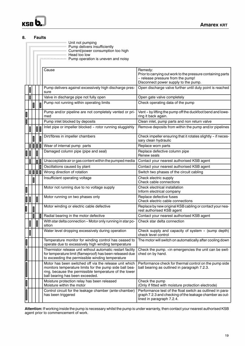
8. FaultsUnit not pumpingPump delivers insufficientlyCurrent/power consumption too highHead too lowPump operation is uneven and noisy
Cause Remedy:Prior to carrying outwork to the pressure containing parts-- release pressure from the pump!Disconnect power supply to the pump.
Pump delivers against excessively high discharge pres-sure
Open discharge valve further until duty point is reached
Valve in discharge pipe not fully open Open gate valve completelyPump not running within operating limits Check operating data of the pump
Pump and/or pipeline are not completely vented or pri-med
Vent -- by lifting the pump off the duckfoot bend and lowe-ring it back again.
Pump inlet blocked by deposits Clean inlet, pump parts and non return valveInlet pipe or impeller blocked -- rotor running sluggishly Remove deposits from within the pump and/or pipelines
Dirt/fibres in impeller chambers Check impeller ensuring that it rotates slightly -- if neces-sary clean hydraulic
Wear of internal pump parts Replace worn partsDamaged column pipe (pipe and seal) Replace defective column pipe
Renew sealsUnacceptableairorgascontentwithin thepumpedmedia Contact your nearest authorised KSB agent
Oscillations caused by plant Contact your nearest authorised KSB agentWrong direction of rotation Switch two phases of the circuit cabling
Insufficient operating voltage Check electric supplyCheck cable connections
Motor not running due to no voltage supply Check electrical installationInform electrical company
Motor running on two phases only Replace defective fusesCheck electric cable connections
Motor winding or electric cable defective Replacebyneworiginal KSBcabling or contact yournea-rest authorised KSB agent
Radial bearing in the motor defective Contact your nearest authorised KSB agentWith star delta connection -- Motor only running in star po-sition
Check star delta connection
Water level dropping excessively during operation Check supply and capacity of system -- (sump depth)check level control
Temperature monitor for winding control has ceased tooperate due to excessively high winding temperature
Themotor will switch on automatically after cooling down
Thermistor release unit without automatic restart faclityfor temperature limit (flameproof) has been released dueto exceeding the permissible winding temperature
Check the pump. <in emergencies the unit can be swit-ched on by hand.
Motor has been switched off via the release unit whichmonitors temperature limits for the pump side ball bea-ring, because the permissible temperature of the lowerball bearing has been exceeded.
Performance check for thermal control on the pump sideball bearing as outlined in paragraph 7.2.3.
Moisture protection relay has been releasedMoisture within the motor
Check the pump(Only if fitted with moisture protection electrode)
Control circuit for the leakage chamber (ante-chamber)has been triggered
Performance test of the float switch as outlined in para-graph 7.2.3 and checking of the leakage chamber as out-lined in paragraph 7.2.4.
Attention: If working inside the pump is necessary whilst the pump is underwarranty, then contact your nearest authorisedKSBagent prior to commencement of work.

Amarex KRT
20
9. Annex
Annex 1 General pump outline
Annex 2 Sectional drawing with parts list
Annex 2.1 Cable entry from cable cross sections 4x35 mm2
Annex 3 Mechanical seal arrangement with parts list
Annex 4 Dimension table
Annex 5 General arrangement of installation parts
Annex 5.1 General drawing -- Wet well installation stationary with guide wire with parts list
Annex 5.2 General drawing -- Wet well installation transportable with parts list
Annex 5.3 General drawing -- Wet well installation clamp with parts list
Annex 6 Electrical connection diagram
Annex 7.1 Circuit diagram -- Thermal protection monitoring
Annex 7.2 Circuit diagram -- Bearing monitoring
Annex 7.3 Circuit diagram -- Moisture detection monitoring
Annex 7.4 Circuit diagram -- Mechanical seal monitoring
Annex 8.1 Fitting instructions -- Cable entry -- Cable cross sections from 4x35 mm2
Annex 8.2 Fitting instructions -- Assembly instructions -- Cutter
Annex 8.3 Fitting instructions -- Assembly instructions -- Impeller dismantling/fittingwith tapered connection
Annex 8.4 Fitting instructions -- Impeller fitting/with drawing device
Supplementary operating instructions ”Assembly: cable protection of polyamide” Cable cross sections from8x1,5 mm2 bis 4x35 mm2

Amarex KRT
21
Anhang, Appendix, Annexe, Appendice, Anexo
Inhalt, Contens, Index, Indice, ÍndiceSeite, Size,Page, Pagi-na, Lado
Allgemeine PumpendarstellungGeneral pump outlineReprésentation générale de la pompeRappresentazione generale della pompaRepresentación general de la bomba
23
Gesamtzeichnung Aggregat mit TeilelisteSectional drawing with parts listPlan d‘ensemble -- Groupe avec liste des piècesDisegno di insieme con elenco delle partiPlano de conjunto y lista de despiece
27
LeitungsdurchführungCable entryPassage de câblePassacaviPaso de cable
39
Einbauplan Gleitringdichtung mit TeilelisteMechanical seal arrangement with parts listPlan de montage -- Garniture mécanique avec liste des piècesSchema di montaggio della tenuta meccanica con elenco delle partiPlano para montaje del cierre mecánico con lista de piezas
43
MaßtabellenDimension tableTableau des cotesTabelle degli ingombriTablas de dimensiones
47
Allgemeine Darstellung Aufstell-SetGeneral arrangement of installation partsReprésentation générale -- Jeu d‘installationRappresentazione generale del set di accessori per l‘installazioneRepresentación general juego de accesorios para montaje
52
Gesamtzeichnung -- Naßaufstellung Führungsseil mit TeilelisteGeneral drawing -- Wet well installation stationary with guide wire with parts listPlan d‘ensemble -- Montage immergé -- Câble de guidage avec liste des piècesDisegno di insieme -- Installazione sommersa e fune di guida, con elenco delle partiPlano de conjunto -- instalación en húmedo con cable guía y lista de piezas
53
Elektrische Anschlußpläne Nr. 10Electrical connection diagram Nr. 11Schémas de connexion électriquesSchemi di collegamento elettricoEsquemas de conexión eléctrica
5961
Funktionsplan -- Thermische Motorüberwachung Nr. A3Circuit diagram -- Thermal protection monitoring Nr. A13Plan fonctionnel -- Surveilance thermique du moteurSchema di funzionamento -- Controllo termico del motoreEsquema de funcionamiento -- Protección térmica del motor
6365
Funktionsplan -- Feuchtschutzüberwachung Nr. BCircuit diagram -- Moisture detection monitoringPlan fonctionnel -- Surveillance de la protection contre l‘humiditéSchema di funzionamento -- Controllo dell‘umidità nel motoreEsquema de funcionamiento -- Dispositivo de control de humedad
67

Amarex KRT
22
Anhang, Appendix, Annexe, Appendice, Anexo
Inhalt, Contens, Index, Indice, ÍndiceSeite, Size,Page, Pagi-na, Lado
Funktionsplan -- Gleitrindichtungs-Überwachung Nr. CCircuit diagram -- Mechanical seal monitoringPlan fonctionnel -- Surveillance de la garniture mécaniqueSchema di funzionamento -- Controllo delle tenuta meccanicaEsquema de funcionamiento -- Control cierre mecanico
69
Funktionsplan -- Kugellager-Überwachung Nr. DCircuit diagram -- Bearing monitoringPlan fonctionnel -- Surveillance de la témperature des roulements á billesSchema di funzionamento --- Controllo del cuscinettiEsquema de funcionamiento --- Control de rodamiento
70
Montageanweisung -- Leitungsdurchführung Nr. 8.1.2Fitting instructions -- Cable entryInstructions de montage -- Passage de cábleInstruzioni di montaggio -- Passa cavoInstrucciones de montaje -- paso del cable
71
Montageanweisung -- Laufrad Auf-/Abziehvorrichtung Nr. 8.4Fitting instructions -- Impeller fitting/with drawing deviceInstruction de montage -- Dispositif de levée/de dépose de la roueInstruzioni di montaggio -- Dispositivo per montaggio/estrazione della giranteInstrucciones de montaje -- Dispositivo para montaje / desmontaje del rodete
73

Amarex KRT
23
Werk--Nr. bzw. Ident-Nr.Works No. / Identity No.
No de construction / No d‘identificationNr. di matricola / Nr. di codice
No de fabricación / No de ident.
Fig. 1
Aktiengesellschaft
Typ
Ident--Nr. 01 018 135 ZN 3826 - M 9
Nr.QDKNP2 kW
IP68
A cos�oC
PA-IH ml/s
3~ Mot.Nr.HzV
1/min
�x
Aktiengesellschaft
Typ
Ident--Nr. 01 018 136 ZN 3826 - M 10
Nr.QDKNP2 kW
IP68
A cos�oC
PA-IH ml/s
3~ Mot.Nr.HzV
1/minEExd II B PTB-Nr. Ex- X
50--100% n ta= U= VsoC20DIN 44082PTB-Nr.
f1f2 �
Aktiengesellschaft
Ex
Typ
ZN 3826 - M 11
Nr.QDKNP2 kW
IP68
A cos�oC
PA-IH ml/s
3~ Mot.Nr.HzV
1/min(Ex) d2 G3 PTB-Nr. III B/E-
50--100% n ta= U= VsoC20DIN 44082PTB-Nr.
f1f2 �
Ident.-Nr. 01 028 402
Darstellung FabrikschildDiagram data plateReprésentation plaque signalétiqueRappresentazione targhetta di fabbricaRepresentación placa de caracteristicas
-- Version ohne Ex--Schutz-- Version non-flameproof equipment-- Version sans protection antidéflagrante-- Versione non antideflagrante-- Versión sin protección Ex
Pumpen--TypPump typeType de pompeTipo della pompaBomba tipo
Motor--Nr.Motor No.No de moteurNr. del motoreNo de motor
Pumpen--TypPump typeType de pompeTipo della pompaBomba tipo
Motor--Nr.Motor No.No de moteurNr. del motoreNo de motor
Pumpen--TypPump typeType de pompeTipo della pompaBomba tipo
Motor--Nr.Motor No.No de moteurNr. del motoreNo de motor
Werk--Nr. bzw. Ident-Nr.Works No. / Identity No.
No de construction / No d‘identificationNr. di matricola / Nr. di codiceNo de fabricación / Ident· nº
Wichtige Angaben für ErsatzteilbestellungImportant information when ordering replacement parts
Commande de pièces de rechange caracteristiquesScorta di ricambi dati
Datos importantes para la petición de recambios
-- Version mit Ex--Schutz EURO-- Version flameproof equipment EURO-- Version avec protection antideflagrante EURO-- Versione antideflagrante-- Versión con protección Ex EURO
-- Version mit Ex--Schutz VDE-- Version flameproof equipment VDE-- Version avec protection antideflagrante VDE-- Versione antideflagrante VDE-- Versión con protección Ex VDE
Allgemeine PumpendarstellungGeneral pump outlineReprésentation générale de la pompe/Rappresentazione generale della pompaRepresentación general de la bomba
KRTDN 100...DN 600
414..2804286..3206258..28084310...27010
Motor/Moteur/Motore

Amarex KRT
24
Bild 3
M=180
fürKRT 600-520/600-710M=25
903.03411.03
Mot. �414,286,258,4310
Fig. 2a Fig. 2b
Fig. 4
81-29.02
81-11.01
900.24
932.24
Fig. 5
A
81-29.02
A B
B

Amarex KRT
25
Fig. 8
903.04411.04
Mot. �414,286,258,4310
Fig. 6
Fig. 7
M
R
M
R
M
R

Amarex KRT
26
411.01
903.01
636.01
636.02
903.02
Fig. 10
411.02
A
A
Fig. 9
903.05411.05
903.03411.03
Mot. � 784,806,678,4310
KRT 600-520/600-710
Fig. 11
A
903.03411.03
59--15

Motor/Moteur/Motore
GesamtzeichnungGeneral arrangementPlan d’ensembleDisegno di insiemePlano de conjunto
KRT K 350/500
2606, 32062258, 280821510
Rh.--Nr. 2553.214-90
Amarex KRT
27
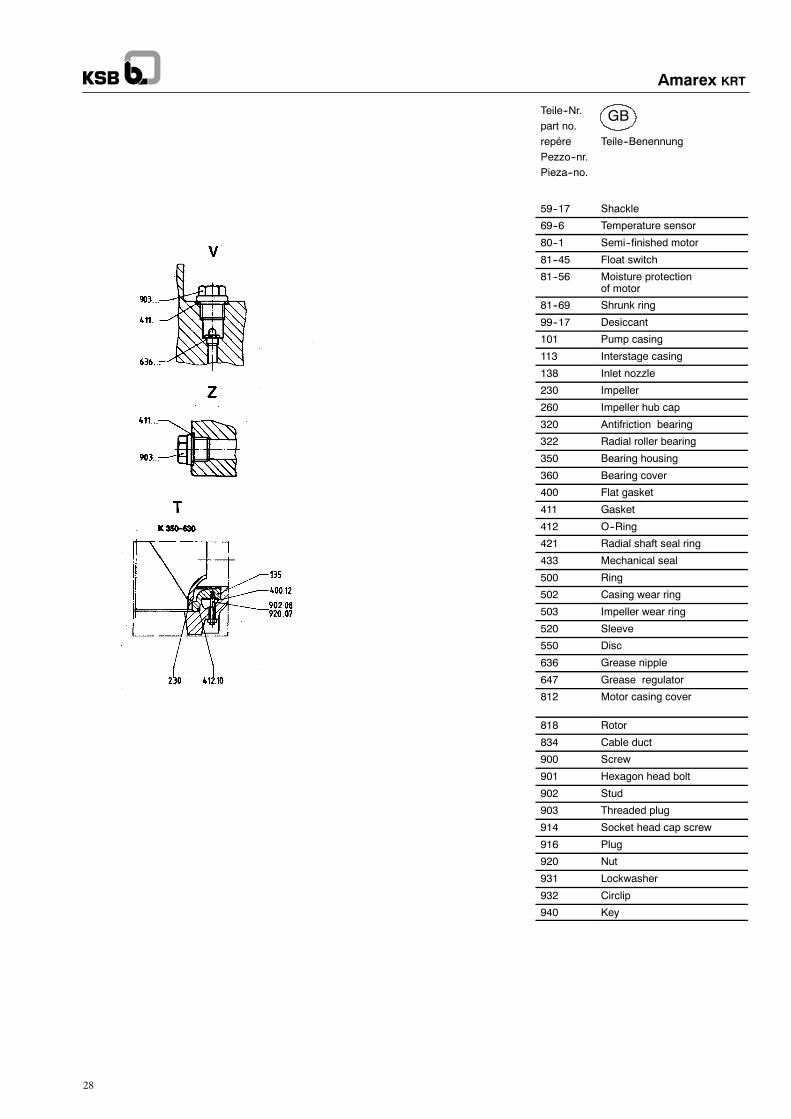
GB
Amarex KRT
28
Teile--Nr.part no.repére Teile--BenennungPezzo--nr.Pieza--no.
59--17 Shackle
69--6 Temperature sensor
80--1 Semi--finished motor
81--45 Float switch
81--56 Moisture protectionof motor
81--69 Shrunk ring
99--17 Desiccant
101 Pump casing
113 Interstage casing
138 Inlet nozzle
230 Impeller
260 Impeller hub cap
320 Antifriction bearing
322 Radial roller bearing
350 Bearing housing
360 Bearing cover
400 Flat gasket
411 Gasket
412 O--Ring
421 Radial shaft seal ring
433 Mechanical seal
500 Ring
502 Casing wear ring
503 Impeller wear ring
520 Sleeve
550 Disc
636 Grease nipple
647 Grease regulator
812 Motor casing cover
818 Rotor
834 Cable duct
900 Screw
901 Hexagon head bolt
902 Stud
903 Threaded plug
914 Socket head cap screw
916 Plug
920 Nut
931 Lockwasher
932 Circlip
940 Key

Motor/Moteur/Motore
GesamtzeichnungGeneral arrangementPlan d’ensembleDisegno di insiemePlano de conjunto
KRT K 600-520
1268...180810710, 12610
Rh.--Nr. 2553.216-90
OW 309019-00
Amarex KRT
29

D
Amarex KRT
30
Teile--Nr.part no.repére Teile--BenennungPezzo--nr.Pieza--no.
59--17 Shackle
69--6 Temperature sensor
80--1 Semi--finished motor
81--45 Float switch
81--56 Moisture protectionof motor
99--17 Desiccant
101 Pump casing
113 Interstage casing
135 Wear plate
138 Inlet nozzle
230 Impeller
260 Impeller hub cap
320 Antifriction bearing
322 Radial roller bearing
350 Bearing housing
360 Bearing cover
411 Gasket
412 O--Ring
421 Radial shaft seal ring
433 Mechanical seal
500 Ring
502 Casing wear ring
503 Impeller wear ring
509 Intermediate ring
520 Sleeve
550 Disc
636 Grease nipple
647 Grease regulator
812 Motor casing cover
818 Rotor
834 Cable duct
900 Screw
901 Hexagon head bolt
902 Stud
903 Threaded plug
914 Socket head cap screw
916 Plug
920 Nut
931 Lockwasher
932 Circlip
940 Key

Motor/Moteur/Motore
GesamtzeichnungGeneral arrangementPlan d’ensembleDisegno di insiemePlano de conjunto
KRT K 600-520
22582808
Rh.--Nr. 2553.217-90
OW 309020-00
Amarex KRT
31

D
Amarex KRT
32
Teile--Nr.part no.repére Teile--BenennungPezzo--nr.Pieza--no.
59--17 Shackle
69--6 Temperature sensor
80--1 Semi--finished motor
81--45 Float switch
81--56 Moisture protectionof motor
81--69 Shrunk ring
99--17 Desiccant
101 Pump casing
113 Interstage casing
135 Wear plate
138 Inlet nozzle
230 Impeller
260 Impeller hub cap
320 Antifriction bearing
322 Radial roller bearing
350 Bearing housing
360 Bearing cover
411 Gasket
412 O--Ring
421 Radial shaft seal ring
433 Mechanical seal
500 Ring
502 Casing wear ring
503 Impeller wear ring
509 Intermediate ring
520 Sleeve
550 Disc
636 Grease nipple
647 Grease regulator
812 Motor casing cover
818 Rotor
834 Cable duct
900 Screw
901 Hexagon head bolt
902 Stud
903 Threaded plug
914 Socket head cap screw
916 Plug
920 Nut
931 Lockwasher
932 Circlip
940 Key

Motor/Moteur/Motore
GesamtzeichnungGeneral arrangementPlan d’ensembleDisegno di insiemePlano de conjunto
KRT K 600-710
21510...27010
Rh.--Nr. 2553.219-90
OW 309021-00
Amarex KRT
33

D
Amarex KRT
34
Teile--Nr.part no.repére Teile--BenennungPezzo--nr.Pieza--no.
59--17 Shackle
69--6 Temperature sensor
80--1 Semi--finished motor
81--45 Float switch
81--56 Moisture protectionof motor
81--69 Shrunk ring
99--17 Desiccant
101 Pump casing
113 Interstage casing
138 Inlet nozzle
230 Impeller
260 Impeller hub cap
320 Antifriction bearing
322 Radial roller bearing
350 Bearing housing
360 Bearing cover
411 Gasket
412 O--Ring
421 Radial shaft seal ring
433 Mechanical seal
500 Ring
502 Casing wear ring
503 Impeller wear ring
509 Intermediate ring
520 Sleeve
550 Disc
636 Grease nipple
647 Grease regulator
812 Motor casing cover
818 Rotor
834 Cable duct
900 Screw
901 Hexagon head bolt
902 Stud
903 Threaded plug
914 Socket head cap screw
916 Plug
920 Nut
931 Lockwasher
932 Circlip
940 Key
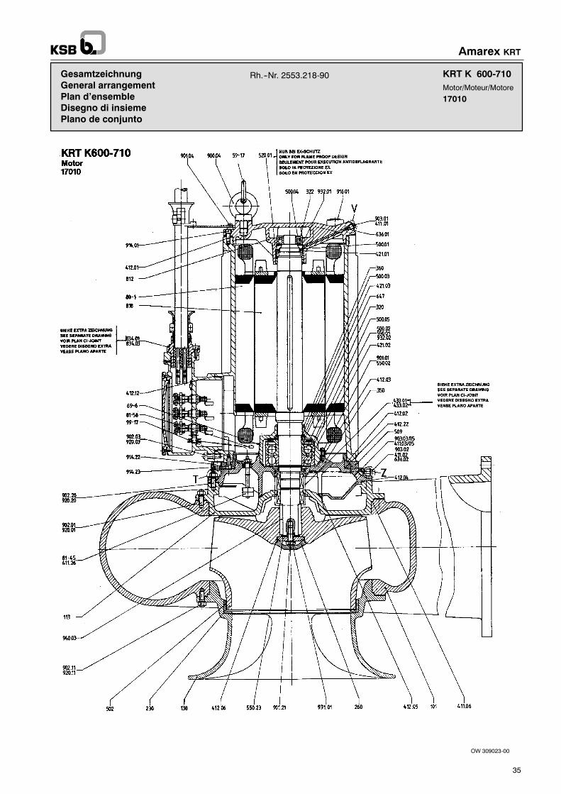
Motor/Moteur/Motore
GesamtzeichnungGeneral arrangementPlan d’ensembleDisegno di insiemePlano de conjunto
KRT K 600-710
17010
Rh.--Nr. 2553.218-90
OW 309023-00
Amarex KRT
35

D
Amarex KRT
36
Teile--Nr.part no.repére Teile--BenennungPezzo--nr.Pieza--no.
59--17 Shackle
69--6 Temperature sensor
80--1 Semi--finished motor
81--45 Float switch
81--56 Moisture protectionof motor
99--17 Desiccant
101 Pump casing
113 Interstage casing
138 Inlet nozzle
230 Impeller
260 Impeller hub cap
320 Antifriction bearing
322 Radial roller bearing
350 Bearing housing
360 Bearing cover
411 Gasket
412 O--Ring
421 Radial shaft seal ring
433 Mechanical seal
500 Ring
502 Casing wear ring
503 Impeller wear ring
509 Intermediate ring
520 Sleeve
550 Disc
636 Grease nipple
647 Grease regulator
812 Motor casing cover
818 Rotor
834 Cable duct
900 Screw
901 Hexagon head bolt
902 Stud
903 Threaded plug
914 Socket head cap screw
916 Plug
920 Nut
931 Lockwasher
932 Circlip
940 Key

Amarex KRT
37

D
GB
F
I
E
Amarex KRT
38
Teile--Nr. Teile--Benennung
81--11 Erdungsanschluß81--22 Klem--Kast--Deckel81--29 Klemme81--36 Klem--Kast--Unterteil81--39 Schelle81--54 Platte81--73 Kabelauflage81--99 Elektroteil411 Dichtring412 O--Ring825 Kabelschutzleiste834 Leitungsdurchführung900 Schraube903 Verschlußschraube914 Innen--6--kt--Schraube932 Sicherungsring
part no. Part description
81--11 Earthing connection81--22 Junction box cover81--29 Clamp81--36 Base of terminal box81--39 Clamp81--54 Plate81--73 Cable support81--99 Electrical part411 Gasket412 O--Ring825 Cable cuard834 Cable duct900 Screw903 Threaded plug914 Socket head cap screw932 Circlip
repére Désignation
81--11 Prise de terre81--22 Couvercle boîte à bornes81--29 Borne81--36 Partie inf. de bÔite à bornes81--39 Collier81--54 Plaque81--73 Support de câble81--99 Partie électrique411 Bague d’ étanchéité412 Joint torique825 Protège--câble834 Passage de câble900 Vis903 Bouchon fileté914 Boulon à 6 pans creux932 Circlip
Pezzo--nr. Denominazione
81--11 Attaco di messa a terra81--22 Coperchio Morsettiera81--29 Morsetto81--36 Parte inferiore morsetierra81--39 Fascia81--54 Piastra81--73 Sostegno per cavo81--99 Parte elettrica411 Anello di guarnizione412 O--Ring (o--anello)825 Ustella di protezione del cavo834 Passacavo900 Vite903 Tappo914 Vite ad esagono cavo932 Anello di sicurezza
Pieza--no. Denominación de la pieza
81--11 puesta a tierra81--22 tapa de la caja de bornas81--29 borna81--36 parte inf. de la caja de bornas81--39 abrazadera81--54 placa81--73 apoyo de cable81--99 parte eléctrica411 anillo de junta412 junta tórica825 listón protector del cable834 paso de cable900 tornillo903 tornillo de cierre914 tornillo hexagonal interior932 anillo de seguridad

KRT DN 200/300/350500/600
2104.....28041386.....32061268.....280810710...27010
Motor
LeitungsdurchführungCable entryPassage de cableIntroducción cablePaso de cable
Amarex KRT
39
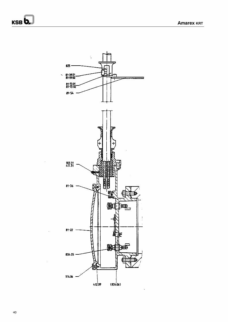
Amarex KRT
40
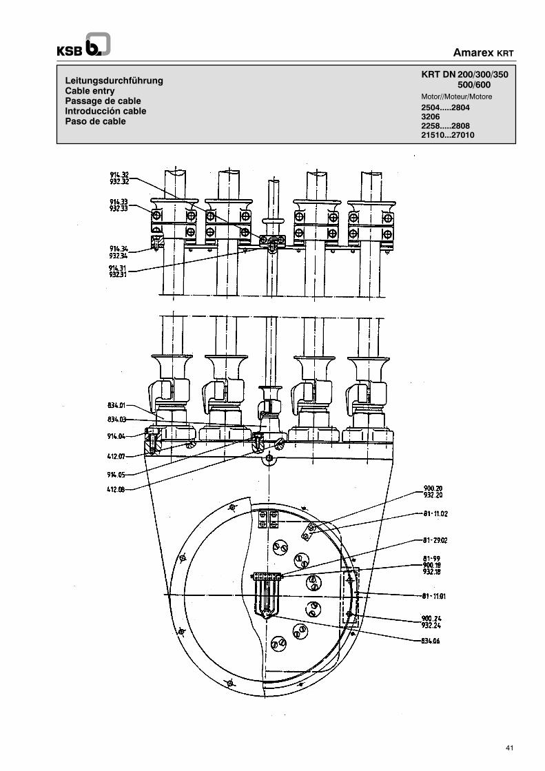
LeitungsdurchführungCable entryPassage de cableIntroducción cablePaso de cable
KRT DN 200/300/350500/600
2504.....280432062258.....280821510...27010
Motor//Moteur/Motore
Amarex KRT
41

D
GB
F
I
E
Amarex KRT
42
Teile--Nr. Teile--Benennung
81--11 Erdungsanschluß81--22 Klem--Kast--Deckel81--29 Klemme81--36 Klem--Kast--Unterteil81--39 Schelle81--54 Platte81--73 Kabelauflage81--99 Elektroteil411 Dichtring412 O--Ring825 Kabelschutzleiste834 Leitungsdurchführung900 Schraube903 Verschlußschraube914 Innen--6--kt--Schraube932 Sicherungsring
part no. Part description
81--11 Earthing connection81--22 Junction box cover81--29 Clamp81--36 Base of terminal box81--39 Clamp81--54 Plate81--73 Cable support81--99 Electrical part411 Gasket412 O--Ring825 Cable cuard834 Cable duct900 Screw903 Threaded plug914 Socket head cap screw932 Circlip
repére Désignation
81--11 Prise de terre81--22 Couvercle boîte à bornes81--29 Borne81--36 Partie inf. de bÔite à bornes81--39 Collier81--54 Plaque81--73 Support de câble81--99 Partie électrique411 Bague d’ étanchéité412 Joint torique825 Protège--câble834 Passage de câble900 Vis903 Bouchon fileté914 Boulon à 6 pans creux932 Circlip
Pezzo--nr. Denominazione
81--11 Attaco di messa a terra81--22 Coperchio Morsettiera81--29 Morsetto81--36 Parte inferiore morsetierra81--39 Fascia81--54 Piastra81--73 Sostegno per cavo81--99 Parte elettrica411 Anello di guarnizione412 O--Ring (o--anello)825 Ustella di protezione del cavo834 Passacavo900 Vite903 Tappo914 Vite ad esagono cavo932 Anello di sicurezza
Pieza--no. Denominación de la pieza
81--11 puesta a tierra81--22 tapa de la caja de bornas81--29 borna81--36 parte inf. de la caja de bornas81--39 abrazadera81--54 placa81--73 apoyo de cable81--99 parte eléctrica411 anillo de junta412 junta tórica825 listón protector del cable834 paso de cable900 tornillo903 tornillo de cierre914 tornillo hexagonal interior932 anillo de seguridad

Einbauplan GleitringdichtungDetail mechanical sealPlan de détail garniture mécaniqueSchema di montaggio della tenuta meccanicaPlano para montaje del cierre mecánico
KRT DN 200 --DN 600
2104 ... 28041386 ... 32061268 ... 280810710 ... 27010
Motor/Moteur
W 309110--00
433.01
524
550.03
932.03
500.06
914.07
433.02
940.13
412.17
Nur bei MotorgrößenOnly for motor sizesUniquement pour les tailles de moteurValido solamente per motoriSólo para tamaños de motor2606,32062258,2808,21510,23510,27010
Amarex KRT
43

D
GB
F
I
E
Amarex KRT
44
Teile--Nr. Teile--Benennung
412 O--Ring433 Gleitringdichtung500 Ring524 Wellenschutzhülse550 Scheibe914 Innen--6kt--Schraube932 Sicherungsring940 Passfeder
part no. Part description
412 O--Ring433 Mechanical seal500 Ring524 Shaft protecting sleeve550 Disc914 Socket head cap screw932 Circlip940 Key
repére Désignation
412 Joint torique433 Garniture mécanique500 Bague524 Chemise de protection d’arbre550 Disque914 Boulon a 6 pans creux932 Circlip940 Clavette
Pezzo--nr. Denominazione
412 O--Ring (o--anello)433 Tenuta meccanica500 Anello524 Bussola protezione albero550 Disco914 Vite ad esagno cavo932 Anello di sicurezza940 Linguetta
Pieza--no. Denominación de la pieza
412 junta tórica433 cierre mecánico500 anillo524 casquillo protector del eje550 disco914 tornillo hexagonal interior932 anillo de seguridad940 chaveta de ajuste

Einbauplan GleitringdichtungDetail mechanical sealPlan de détail garniture mécaniqueSchema di montaggio della tenuta meccanicaPlano para montaje del cierre mecánico
KRT 600-520
1268 ... 28086710 ... 12610
Motor/Moteur
433.01
550.03
932.03
914.07
500.06
433.02
524
412.17
0W309111--00
Nur bei MotorgrößenOnly for motor sizesUniquement pour les tailles de moteurValido solamente per motoriSólo para tamaños de motor
2258,2808
Amarex KRT
45
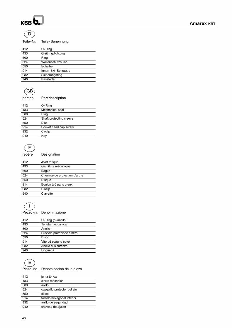
D
GB
F
I
E
Amarex KRT
46
Teile--Nr. Teile--Benennung
412 O--Ring433 Gleitringdichtung500 Ring524 Wellenschutzhülse550 Scheibe914 Innen--6kt--Schraube932 Sicherungsring940 Passfeder
part no. Part description
412 O--Ring433 Mechanical seal500 Ring524 Shaft protecting sleeve550 Disc914 Socket head cap screw932 Circlip940 Key
repére Désignation
412 Joint torique433 Garniture mécanique500 Bague524 Chemise de protection d’arbre550 Disque914 Boulon à 6 pans creux932 Circlip940 Clavette
Pezzo--nr. Denominazione
412 O--Ring (o--anello)433 Tenuta meccanica500 Anello524 Bussola protezione albero550 Disco914 Vite ad esagno cavo932 Anello di sicurezza940 Linguetta
Pieza--no. Denominación de la pieza
412 junta tórica433 cierre mecánico500 anillo524 casquillo protector del eje550 disco914 tornillo hexagonal interior932 anillo de seguridad940 chaveta de ajuste

KRT 200-500KRT 200-501
MaßtabelleDimension tableTableau de dimensionsTabella degli ingombriTablas de dimensiones
Rh.--Nr.: 2553.309-90A.N. 30 235
Amarex KRT
47

KRT 300-400KRT 300-500
MaßtabelleDimension tableTableau de dimensionsTabella degli ingombriTablas de dimensiones
Rh.--Nr.: 2553.311-90A.N. 30 237
Amarex KRT
48

KRT 350MaßtabelleDimension tableTableau de dimensionsTabella degli ingombriTablas de dimensiones
Rh.--Nr.: 2553.312-90
Amarex KRT
49

KRT 500MaßtabelleDimension tableTableau de dimensionsTabella degli ingombriTablas de dimensiones
Rh.--Nr.: 2553.313-90A.N. 30 239
Amarex KRT
50

KRT 600MaßtabelleDimension tableTableau de dimensionsTabella degli ingombriTablas de dimensiones
Rh.--Nr.: 2553.314-90A.N. 30 240
Amarex KRT
51

Amarex KRT
52
Fig.1 Fig.3
Fig.2
P/2
Z
P/2
ZMA
P
Allgemeine Darstellung Aufstell-SetGeneral illustration of assembly kitReprésentation générale -- Jeu d‘installationRappresentazione generale del set di accessori per l‘installazioneRepresentación general juego de accesorios para montaje
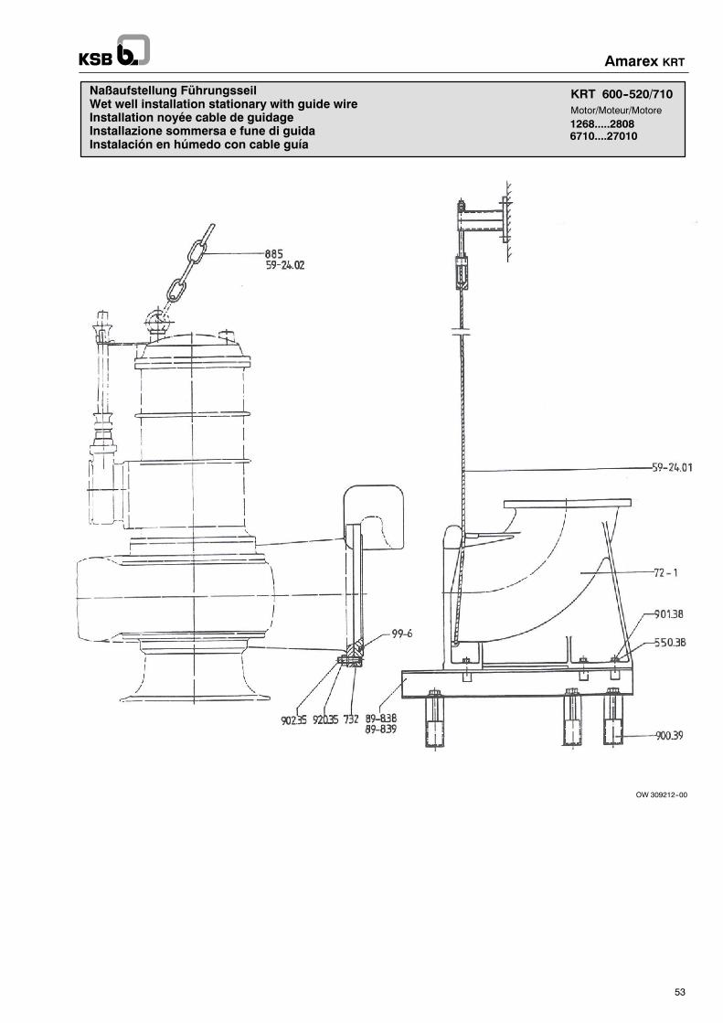
KRT 600--520/710
1268.....28086710....27010
Motor/Moteur/Motore
Naßaufstellung FührungsseilWet well installation stationary with guide wireInstallation noyée cable de guidageInstallazione sommersa e fune di guidaInstalación en húmedo con cable guía
OW 309212--00
Amarex KRT
53
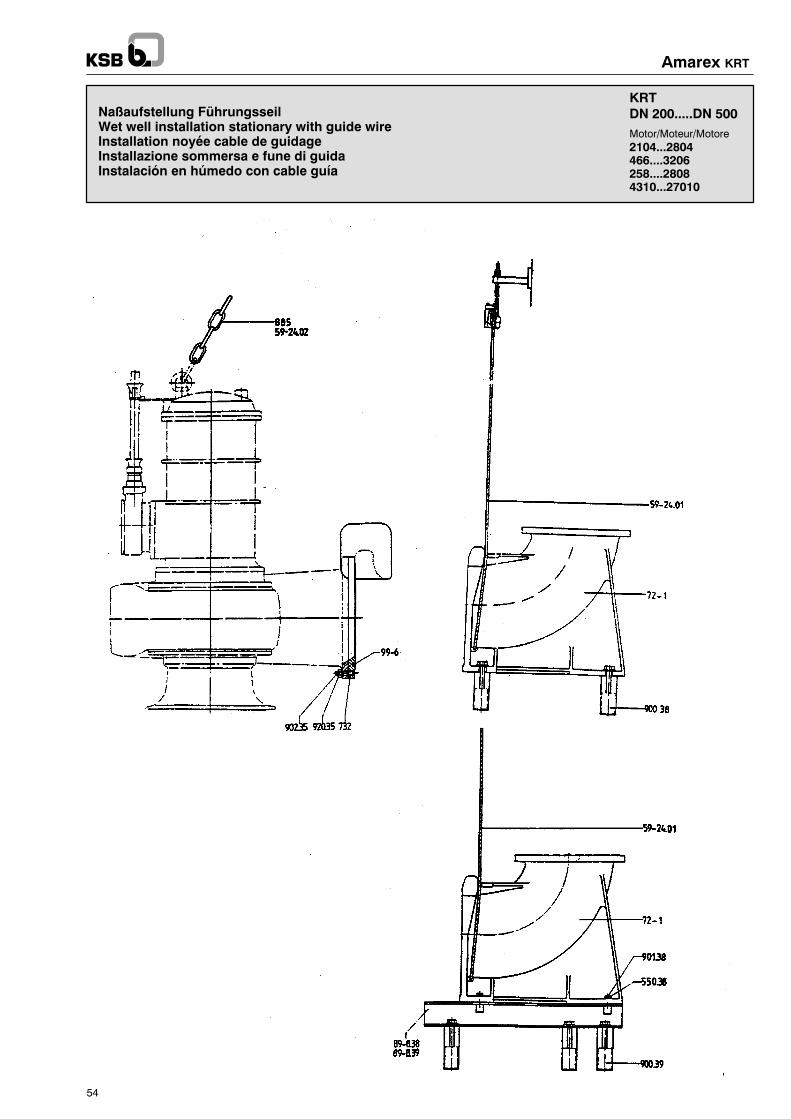
Naßaufstellung FührungsseilWet well installation stationary with guide wireInstallation noyée cable de guidageInstallazione sommersa e fune di guidaInstalación en húmedo con cable guía
KRTDN 200.....DN 500
2104...2804466....3206258....28084310...27010
Motor/Moteur/Motore
OW 309209-00OW 309210-00OW 309211-00
Amarex KRT
54
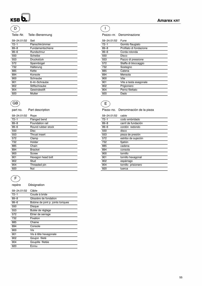
D
GB
F
I
E
Amarex KRT
55
Teile--Nr. Teile--Benennung
59--24.01/02 Seil72--1 Flanschkrümmer89--8 Fundamentschiene99--6 Rundschnur550 Scheibe553 Druckstück572 Spannbügel732 Halterung885 Kette894 Konsole900 Schraube901 6--kt--Schraube902 Stiftschraube904 Gewindestift920 Mutter
part no. Part description
59--24.01/02 Rope72--1 Flanged bend89--8 Foundation rail99--6 Round rubber stock550 Disc553 Thrust insert572 Clamp732 Holder885 Chain894 Bracket900 Screw901 Hexagon head bolt902 Stud904 Threaded pin920 Nut
repére Désignation
59--24.01/02 Câble72--1 Coude à bride89--8 Glissière de fondation99--6 Bobine de joint p. joints toriques550 Disque553 Butée de réglage572 Etrier de serrage732 Fixation885 Chaine894 Console900 Vis901 Vis à tête hexagonale902 Goujon fileté904 Goupille filetée920 Ecrou
Pezzo--nr. Denominazione
59--24.01/02 Fune72--1 Gomito flaugiato89--8 Profilato di fondazione99--6 Corda rotonda550 Disco553 Pazzo di pressione572 Staffa di bloccaggio732 Sostegno885 Catena894 Mensola900 Vite901 Vite a testa esagonale902 Prigioniero904 Perno filettato920 Dado
Pieza--no. Denominación de la pieza
59--24.01/02 cable72--1 codo embridado89--8 carril de fundación99--6 cordón redondo550 disco553 pieza de presión572 estribo de sujeción732 fijatión885 cadena894 consola900 tornillo901 tornillo hexagonal902 espárrago904 tornillo prisionero920 tuerca
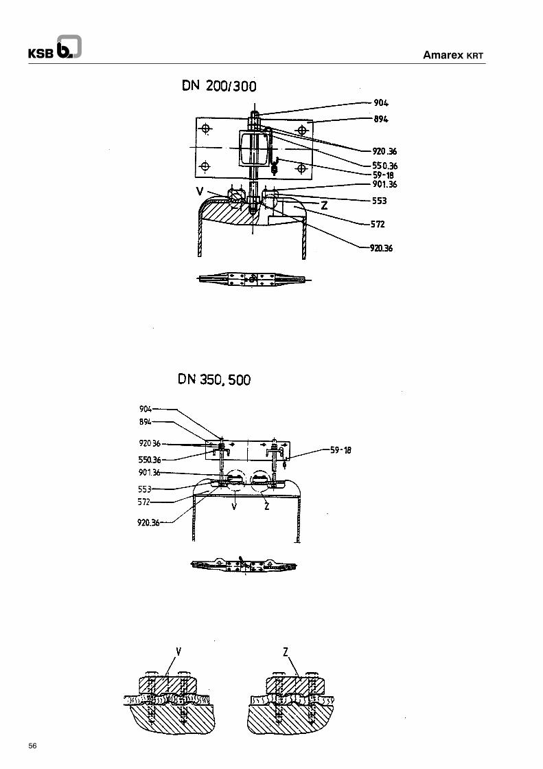
Amarex KRT
56
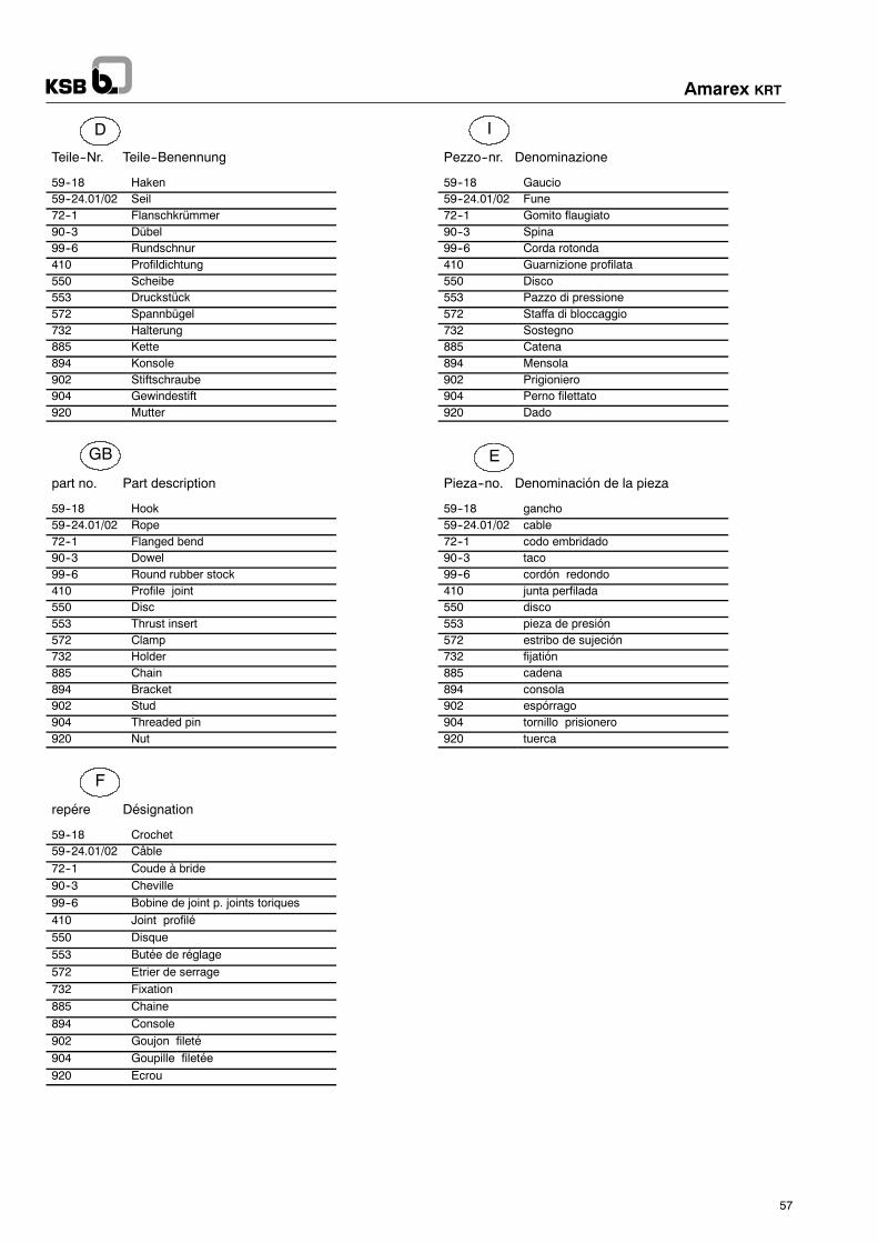
D
GB
F
I
E
Amarex KRT
57
Teile--Nr. Teile--Benennung
59--18 Haken59--24.01/02 Seil72--1 Flanschkrümmer90--3 Dübel99--6 Rundschnur410 Profildichtung550 Scheibe553 Druckstück572 Spannbügel732 Halterung885 Kette894 Konsole902 Stiftschraube904 Gewindestift920 Mutter
part no. Part description
59--18 Hook59--24.01/02 Rope72--1 Flanged bend90--3 Dowel99--6 Round rubber stock410 Profile joint550 Disc553 Thrust insert572 Clamp732 Holder885 Chain894 Bracket902 Stud904 Threaded pin920 Nut
repére Désignation
59--18 Crochet59--24.01/02 Câble72--1 Coude à bride90--3 Cheville99--6 Bobine de joint p. joints toriques410 Joint profilé550 Disque553 Butée de réglage572 Etrier de serrage732 Fixation885 Chaine894 Console902 Goujon fileté904 Goupille filetée920 Ecrou
Pezzo--nr. Denominazione
59--18 Gaucio59--24.01/02 Fune72--1 Gomito flaugiato90--3 Spina99--6 Corda rotonda410 Guarnizione profilata550 Disco553 Pazzo di pressione572 Staffa di bloccaggio732 Sostegno885 Catena894 Mensola902 Prigioniero904 Perno filettato920 Dado
Pieza--no. Denominación de la pieza
59--18 gancho59--24.01/02 cable72--1 codo embridado90--3 taco99--6 cordón redondo410 junta perfilada550 disco553 pieza de presión572 estribo de sujeción732 fijatión885 cadena894 consola902 espórrago904 tornillo prisionero920 tuerca
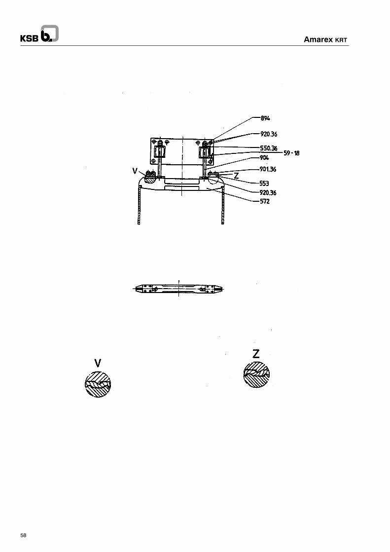
Amarex KRT
58

Elektrischer AnschlußplanElectrical connection diagramSchema de connexion électriquesSchema del collegamento elettricoEsquema de conexión eléctrica
2104.....2804,1386....2606,1268....2808,10710.....23510
Motor/Moteur/Motore
Nr.10G
Feuchtschutzüberwachung
Moistruredetectionmonitoring
Surveillance
delaprotectioncontrel‘hum
iditè
Controllodell‘um
idita
nelm
otore
Dispositivode
controldehumedad
Gleitringdichtungsüberwachung
Mechanicalsealm
onitoring
Surveillance
delagarnituremècanique
Controllodella
tenutameccanica
Controlcierremecanico
Kugellagertem
peraturüberwachung
Bearingdiagram
Surveillance
delatempèraturedu
Controllodella
temperaturadelcuscinetto
asfere
Controlde
temperaturadelrodam
iento
roulem
enta
billes
Nr.10
Nr.A3
Nr.A13
Nr.B
Nr.C
Nr.D
2104 X... -- 2804 X...1386 X... -- 2606 X...1268 X... -- 2808 X...10710 X... -- 23510 X...
2104 U... -- 2504 U...1386 U... -- 2606 U...1268 U... -- 2258 U...10710 U... -- 21510 U...
2104 W...1386 W... -- 2006 W...1268 W... -- 1808 W...10710 W... -- 17010 W...
Y / �
Amarex KRT
59
Elektrischer AnschlußplanElectrical connection diagram
Schema de connexion électriquesSchema del collegamento elettricoEsquema de conexión eléctrica
ThermischeMotorüberwachung
Thermal protection monito-ring
Surveillance thermique dumoteur
Controllo termico del motoreProtección térmica del motor
Mot. U, W X
2 Kraftleitungen, 2 Power cable, 2 ligue de force, 2 cables de fuerza

0W380165
1020 21 411 3 915 16
(1)
(2)
(3)
(4)
(5)
(6)
(7)
(8)
(9)
U1
V1
W1
PE
4 410
10 11 9
B2
R1
R2
R3
B3
P
432120
F4
F5
15 16
R9
U1 V1 W1
U2 V2 W2
3 ~
U1
W2
V1 U2
W1
V2 PE
PE
U1
U2
V1
V2 W1
W2
PE
PE
20 21 10 11 3 4 15
U1
V1 W1
U2
V2 W2
PE
PE
L1 L2 L3 PE
16 920 21 10 11 3 4 15 16 9
20 21 10 11 3 4 15 16 9
20 21 10 11 3 4 15 16 9W2
V2
U2
PE
(10)
(11)
(12)
D
Amarex KRT
60
KabelkennzeichnungAderkenn- Aderkennziffernband bzw. Farben
Kraftleitung
NSSHÖU-J: U1 -- U2 schwarzV1 -- V2 braunW1 -- W2 blau
Steuerleitung
NSSHÖU-J: 20 (1)21 (2)10 (311 (4)3 (5)4 (6)15 (7)16 (8)9 (9)
Tefzel: 20 schwarz21 orange10 blau11,3,4,15,16,9 schwarz
Überwachungseinrichtungen
Wicklungs-Temperaturfühler:
R1,R2,R3: PTC-Thermistoren (Kaltleiter)Kennbänder 10,11
F4,F5: Bimetallschalter (Öffner)Kennbänder 21,22
Motor-Feuchtigkeitsschutz:
B2: Feuchtschutzelektrodeim MotorraumKennband 9
Gleitringdichtungs-Überwachung
B3: Schwimmerschalter (Öffner)in der LeckagekammerKennbänder 3,4
Pumpenseitige Kugellager--Überwachung
R9: Pt100Kennbänder 15,16

Elektrischer AnschlußplanElectrical connection diagramSchema de connexion électriquesSchema del collegamento elettricoEsquema de conexión eléctrica
2804,2606....3206,2258....2808,21510.....27010
Motor/Moteur/Motore
Nr.11G
Feuchtschutzüberwachung
Moistruredetectionmonitoring
Surveillance
delaprotectioncontrel‘hum
iditè
Controllodell‘um
idita
nelm
otore
Dispositivode
controldehumedad
Gleitringdichtungsüberwachung
Mechanicalsealm
onitoring
Surveillance
delagarnituremècanique
Controllodella
tenutameccanica
Controlcierremecanico
Kugellagertem
peraturüberwachung
Bearingdiagram
Surveillance
delatempèraturedu
Controllodella
temperaturadelcuscinetto
asfere
Controlde
temperaturadelrodam
iento
roulem
enta
billes
Nr.11
Nr.A3
Nr.A13
Nr.B
Nr.C
Nr.D
2804 X...3206 X...27010 X...
2804 U...3206 U...2808 U...23510 U... -- 27010 U...
2804 W...2606 W... -- 3206 W...2258 W... -- 2808 W...21510 W... -- 27010 W...
Y / �
Amarex KRT
61
Elektrischer AnschlußplanElectrical connection diagram
Schema de connexion électriquesSchema del collegamento elettricoEsquema de conexión eléctrica
ThermischeMotorüberwachung
Thermal protection monito-ring
Surveillance thermique dumoteur
Controllo termico del motoreProtección térmica del motor
Mot. U, W X
4 Kraftleitungen, 4 Power cable , 4 ligue de force, 4 cables de fuerza

0W380166
3 ~
1020 21 411 3 915 16U1--1
V1--1
W1--1
PE
(1)
(2)
(3)
(4)
(5)
(6)
(7)
(8)
(9)
U1--2
V1--2
W1--2
PE
U2--1
V2--1
W2--1
PE
U2--2
V2--2
W2--2
PE
U1-1
U1-2
W1-1
W1-2
W2-1
W2-2
V2-1
V2-2
V1-1
V1-1
V1-2
U1-1
U1-2
W1-1
W1-2
U2-1
U2-2
V2-1
V2-2
W2-1
W2-2
20 21PE
PE
PE
PE
V1-1
V1-2
U1-1
U1-2
W1-1
W1-2
U2-1
U2-2
V2-1
V2-2
W2-1
W2-2
V1-2
U2-1
U2-2
L1 L2
L1 L2 L3
L3 PE
PE
PE
PE
PE
PE
PE
PE
PE
PE
PE
10 11 3 4 920 21 10 11 3 4 9
20 21 10 11 3 4 12 13 9
20 21 10 11 3 4 9
4 4104 4
10 11 94321 15 1620
F4
F5R9 B2
B3
P
R1
R2
R3
U1--2
V1--2
W1--2
U1--1
V1--1
W1--1
U2--1
V2--1
W2--1
U2--2
V2--2
W2--2
12 13
12 13
(12)
PE(10)
(11)
PE
PE
PE
D
Amarex KRT
62
KabelkennzeichnungAderkenn- Aderkennziffernband bzw. Farben
Kraftleitung
NSSHÖU-J: U1 ... schwarzV1 ... braunW1... blau
Steuerleitung
NSSHÖU-J: 20 (1)21 (2)10 (311 (4)3 (5)4 (6)15 (7)16 (8)9 (9)
Tefzel: 20 schwarz21 orange10 blau11,3,4,15,16,9 schwarz
Überwachungseinrichtungen
Wicklungs-Temperaturfühler:
R1,R2,R3: PTC-Thermistoren (Kaltleiter)Kennbänder 10,11
F4,F5: Bimetallschalter (Öffner)Kennbänder 21,22
Motor-Feuchtigkeitsschutz:
B2: Feuchtschutzelektrodeim MotorraumKennband 9
Gleitringdichtungs-Überwachung
B3: Schwimmerschalter (Öffner)in der LeckagekammerKennbänder 3,4
Pumpenseitige Kugellager--Überwachung
R9: Pt 100Kennbänder 15,16
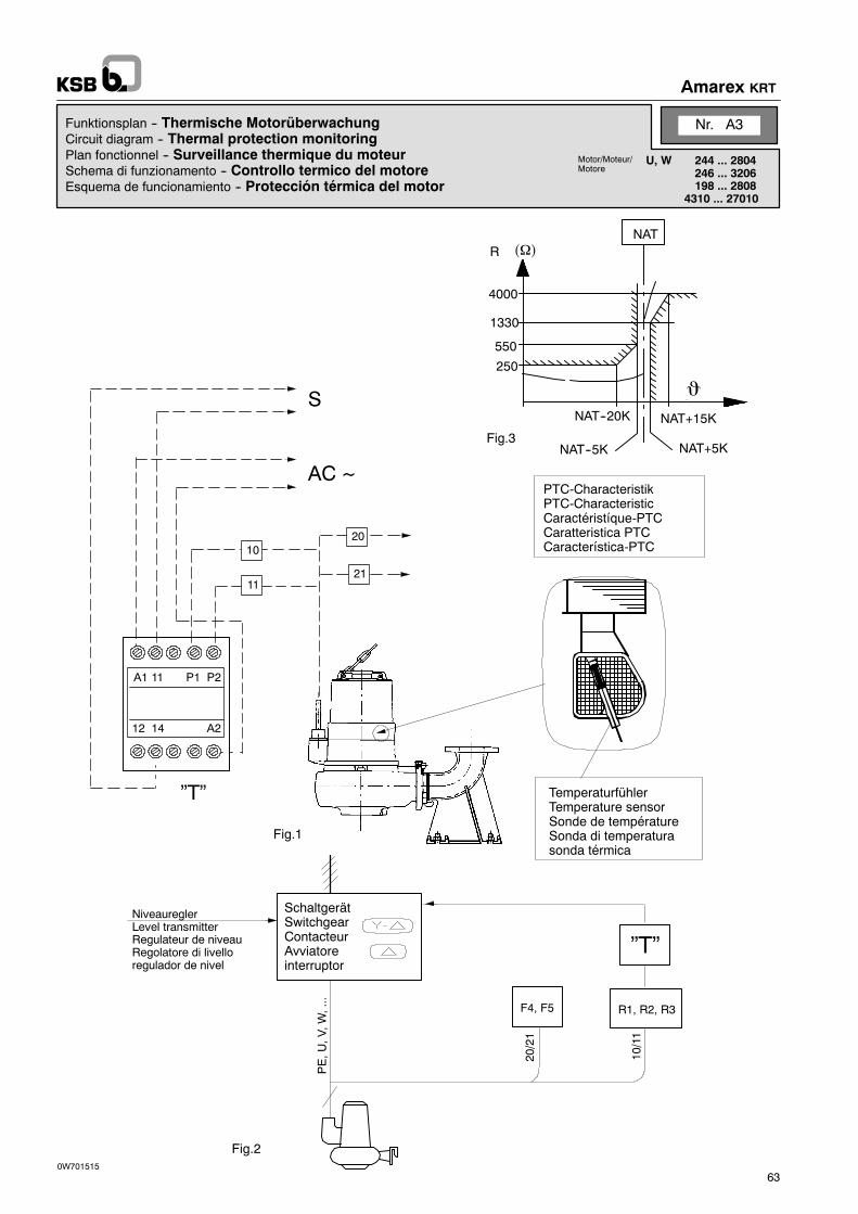
Amarex KRT
63
4000
1330
550
250
NAT--20K
NAT--5K
NAT+15K
NAT+5K
NATR ���
20/21
10/11
�
PTC-CharacteristikPTC-CharacteristicCaractéristíque-PTCCaratteristica PTCCaracterística-PTC
Fig.3
Fig.2
NiveaureglerLevel transmitterRegulateur de niveauRegolatore di livelloregulador de nivel
SchaltgerätSwitchgearContacteurAvviatoreinterruptor
F4, F5 R1, R2, R3
”T”
PE,U
,V,W
,...
A1 11 P2
12 14 A2
10
11
20
21
P1
AC ~
S
”T” TemperaturfühlerTemperature sensorSonde de températureSonda di temperaturasonda térmica
Fig.1
0W701515
Funktionsplan -- Thermische MotorüberwachungCircuit diagram -- Thermal protection monitoringPlan fonctionnel -- Surveillance thermique du moteurSchema di funzionamento -- Controllo termico del motoreEsquema de funcionamiento -- Protección térmica del motor
Nr. A3
U, W 244 ... 2804246 ... 3206198 ... 2808
4310 ... 27010
Motor/Moteur/Motore

D
F4/F5
R1, R2, R3Überwachungskreis
20 21
10 11
Achtung
GB
F4/F5
R1, R2, R3Monitoring circuit
20 21
10 11
N. B.
Amarex KRT
64
Funktionsbeschreibung der Wicklungstemperaturüber-wachung ohne Ex-Schutz
DieWicklung wird durch einen Temperaturüberwachungskreisgeschützt.
Als Temperaturwächter dienen 3 Kaltleiter R1, R2, R3 (Ader-kennband10, 11), welche diePumpebeiErreichender zulässi-gen Wicklungstemperatur ab und nach Abkühlen selbsttätigwieder einschalten.
Dies erfordert im Steuerkreis des Motorschützes ein Thermi-stor-Auslösegerät ”T” (Fig. 1) ohne Verriegelung für automati-scheWiedereinschaltung,Eskann jedeshandeslüblicheGeräteingesetzt werden.
Die Bimetallschalter F4/F5 (Aderkennband 20, 21) werdennicht benötigt und sind auf Leerklemmen anzuschließen.
Temperaturschalter
= 2 Bimetallschalter (Öffner)in MotorwicklungAderkennbandmax. Betriebsspannung desSchalters 250 Vmax. Schalterstrom 2 A bei cos � = 1
= 3 PTC Thermistoren (Kaltleiter)in MotorwicklungAderkennbandmax. Betriebsspannung an KlemmenUmax.= 30 V -- GleichstromWiderstand zwischen Klemmen 10/11-- bei Raumtemperatur R 300--750 �-- bei Abschalttemperatur R � 4000 �
Überwachungskreise nicht mit Kurbelin-duktor prüfen. Überprüfung nur mit Ohm-meter.
Description -- non--flameproof thermal cutout
Thewinding is protected against overheating by a temperaturecontrol circuit.
Three PTC- thermistors R1, R2, R3 (identification tape 10, 11)are used for temperaturemonitoring. They switch off the pump-set as soon as the maximum winding temperature is reachedand automatically switch it on again after the winding has coo-led down.
This means that a thermistor control unit ”T” (see fig. 1) withoutinterlocking for automatic re-start is required in the motor con-tactor. Any proprietary make can be used.
The bimetal switches F4, F5 (identification tape 20, 21) are notrequired and should be connected to dummy terminals.
Temperature switch
= 2 bimetal switches in themotor windingIdentification tapemax. operating voltage ofswitch 250 Vmax. current 2 A at cos � = 1
= 3 PTC thermistors in themotor windingIdentification tapemax. operating voltage on terminalsUmax. = 30 V d. c.resistance between terminals 10/11-- at ambient temperature R 300--750�-- at shutdown temperature R � 4000�
Do not test monitoring circuits by meansof a hand megger. Use an ohmmeter.

Amarex KRT
65
4000
1330
550
250
NAT--20K
NAT--5K
NAT+15K
NAT+5K
NATR ���
20/21
10/11
�
Fig.3
Fig.2
F4, F5 R1, R2, R3
”T”
PE,U
,V,W
,...
A1 11 P2
12 14 A2
10
11
20
21
P1
AC ~
S
”T”Fig.1
0W701512
Niveauregler
Level transmitterRegulateur de niveauRegolatore di livelloregulador de nivel
SchaltgerätSwitchgearContacteurAvviatoreinterruptor
TemperaturfühlerTemperature sensorSonde de températureSonde di temperaturasonda térmica
PTC-CharacteristikPTC-CharacteristicCaractéristíque-PTCCaratteristica PTCcaracterística-PTC
Funktionsplan -- Thermische MotorüberwachungCircuit diagram -- Thermal protection monitoringPlan fonctionnel -- Surveillance thermique du moteurSchema di funzionamento -- Controllo termico del motoreEsquema de funcionamiento -- Protección térmica del motor
Nr. A13
X 244 ... 2804 198 ... 2808246 ... 3206 4310 ... 27010
Motor/Moteur/Motore
D
!
F4/F5
R1, R2, R3Begrenzerkreis
20 21
10 11
Überwachungsdreis
Achtung
GB
!
F4/F5
R1, R2, R3Temperature
20 21
10 11
Monitoring circuit
control circuit
N. B.
Amarex KRT
66
Funktionsbeschreibung der Wicklungstemperatur-Über-wachung KRT mit Ex-Schutz (siehe auch Anschlußplan)Bei Ex-Schutz wird dieWicklung durch zwei unabhängige Temperatur-Überwachungskreise geschützt.
Als Temperaturwächter dienen zwei Bimetallachalter F4, F5 (Ader-kennband20 ,21) , welchediePumpebeimErreichendermax. zulässi-genWicklungstemperaturabundnachAbkühlenselbsttätigwiederein-schalten.
Dies erfordert, daß sie direkt in denSteuerkreis desMotorschützes ge-schaltet werden.
Zusätzlich sind als Temperaturbegrenzer nochmals 3 PTC-KaltleiterR1, R2, R3 (Aderkennband 10, 11) eingebaut, welche die Pumpe beimeventuellenVersagenderTemperaturwächterabschalten,bevordie fürden Ex-Schutz zulässigen Grenztemperaturen überschritten werden.Eine automatischeWiedereinschaltung ist hierbei nicht zulässig. Dieserfordert im Steuerkreis des Motorschützes ein Thermistor--Auslöse-gerät ”T” (siehe Fig. 1) mit Wiedereinschaltsperre.
Dies ist ein handeslübliches Gerät bzw. kann auch über KSB bezogenwerden.
Beim Umrichterbetrieb muß ein Auslösegerät mit dem Prüfzeichen”PTB3.53-PTC/A2” verwendet werden.
Nach Abschaltung durch die Temperaturbegrenzer ist eine Revisionder Pumpe notwendig. In drengenden Fällen kann bis dahin (nach Ab-kühlen der Maschine) eine Wiedereinschaltung von Hand vorgenom-menwerden. Ein Außerbetriebsetzen der Temperaturbegrenzer ist da-bei nicht zulässig.
DerExplosionsschutz für diePumpen ist nur gegeben,wenndie eingebauten Temperaturschalter (Temperaturwächerund Temperaturbegrenzer) mit den Adern 20, 21, 10 ,11 ge-mäß Bild angeschlossen sind
Temperaturschalter
= 2 Bimetallschalter (Öffner)in MotorwicklungAderkennbandmax. Betriebsspannung desSchalters 250 Vmax. Schalterstrom 2 A bei cos � = 1= 3 PTC Thermistoren (Kaltleiter)in MotorwicklungAderkennbandmax. Betriebsspannung an KlemmenUmax.= 30 V -- GleichstromWiderstand zwischen Klemmen 10/11-- bei Raumtemperatur R 300--750�-- bei Abschalttemperatur R � 4000�
Überwachungskreise nicht mit Kurbelinduktorprüfen. Überprüfung nur mit Ohmmeter.
Funktionsbeschreibung der Wicklungstemperatur-Über-wachung für Einsatz in NIcht Ex-Schutz(siehe Funktionsplan Temperaturüberwachung U,W Nr. A3)
Description-Thermal cutoun KRT-flameproof(see also connection plan)Onflameproofmotors thewindingsareprotectedby two indpendet tem-perature monitoring circuit.
Twobimetal switchesF4, F5(identification tape20, 21)serveas tempe-raturemonitoring deviceswhich, as soonas themax.winding tempera-ture isreached, switch off the pumpandautomatically anagain after thewindings have cooled down.
This requires that the conductors are drectly connected to the controlciruit of the motor contactor.
Three PTC thermistor R1, R2, R3 (identification tape 10, 11) are fittedas additional temperaturecontrols which, in the event of temperatureswitch failure, shut down the pump before the temperature permissiblefor flameproof applications is exceeded.Automatic reset is not allowed.A thermistor control unit ”T” (see fig. 1) with manuell reset must be in-stalled in the control circiut of the motor confactors.
The thermistor control is a commercial product which can also be orde-red through KSB.
For operation with frequency converter, a release device bearing thetext mark ”PTB3.53--PTC/A2” must be used.
If the pump has been shut down by thermistors, it is necessary to over-haut it. in urgent cases the resetmaybeusedafter themotorhas cooleddown. The hermistors must not be made nonoperational at any time.
Flameproof requirements für the pumps are only compliedwith when built-in temperature monitoring devices (bime-tallswitchesand thermistors) includingconductors20, 21,10and 11 are connected up in accordance with fig.
Temperature switch
= 2 bimetall switch in themotor windingIdentification tapemax. operating voltage ofswitch 250 Vmax. current 2 A at cos � = 1
= 3 PTC thermistors in themotor windingIdentification tapemax. operating voltage on terminalsUmax. = 30 V d. c.resistance between terminals 10/11-- at ambient temperature R 300--750�-- at shutdown temperature R � 4000�
Do not test monitoring circuits by means of ahand generator. Use an ohmmeter.
Description of operating method for the winding tempera-ture monitoring equipment for use in non-flameproofequipment.See Circuit diagram ”Thermal protection monitoring” U, WNr. A3.
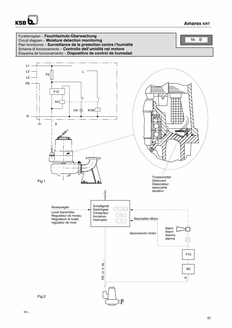
Fig.19PE,U
,V,W
,...
Fig.2
B2
AlarmAlarmAlarmealarma
F10
L1
L2
L3
PE
N
9
F0
F10
K4
L
H4 K1M
TrockenmittelDesiccantDessicateuressiccantesecativo
0W.....
Abschalten Motor
Niveauregler
Level transmitterRegulateur de niveauRegolatore di livelloregulador de nivel
SchaltgerätSwitchgearContacteurAvviatoreinterruptor
Nr. BFunktionsplan -- Feuchtschutz-ÜberwachungCircuit diagram -- Moisture detection monitoringPlan fonctionnel -- Surveillance de la protection contre l‘humiditéSchema di funzionamento -- Controllo dell‘umidità nel motoreEsquema de funcionamiento -- Dispositivo de control de humedad
desconexión motor
Amarex KRT
67
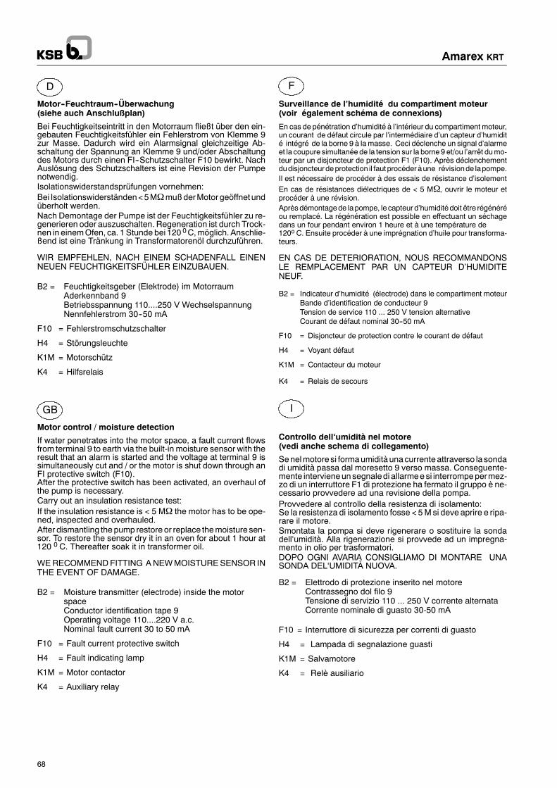
D
GB
F
I
Amarex KRT
68
Motor--Feuchtraum--Überwachung(siehe auch Anschlußplan)
Bei Feuchtigkeitseintritt in den Motorraum fließt über den ein-gebauten Feuchtigkeitsfühler ein Fehlerstrom von Klemme 9zur Masse. Dadurch wird ein Alarmsignal gleichzeitige Ab-schaltung der Spannung an Klemme 9 und/oder Abschaltungdes Motors durch einen FI--Schutzschalter F10 bewirkt. NachAuslösung des Schutzschalters ist eine Revision der Pumpenotwendig.Isolationswiderstandsprüfungen vornehmen:Bei Isolationswiderständen<5M�mußderMotor geöffnetundüberholt werden.Nach Demontage der Pumpe ist der Feuchtigkeitsfühler zu re-generieren oder auszuschalten. Regeneration ist durch Trock-nen in einemOfen, ca. 1Stunde bei 120 0C,möglich. Anschlie-ßend ist eine Tränkung in Transformatorenöl durchzuführen.
WIR EMPFEHLEN, NACH EINEM SCHADENFALL EINENNEUEN FEUCHTIGKEITSFÜHLER EINZUBAUEN.
B2 = Feuchtigkeitsgeber (Elektrode) im MotorraumAderkennband 9Betriebsspannung 110....250 V WechselspannungNennfehlerstrom 30--50 mA
F10 = Fehlerstromschutzschalter
H4 = Störungsleuchte
K1M = Motorschütz
K4 = Hilfsrelais
Motor control / moisture detection
If water penetrates into the motor space, a fault current flowsfrom terminal 9 to earth via the built-in moisture sensor with theresult that an alarm is started and the voltage at terminal 9 issimultaneously cut and / or the motor is shut down through anFI protective switch (F10).After the protective switch has been activated, an overhaul ofthe pump is necessary.Carry out an insulation resistance test:If the insulation resistance is < 5 M� the motor has to be ope-ned, inspected and overhauled.After dismantling the pump restore or replace themoisture sen-sor. To restore the sensor dry it in an oven for about 1 hour at120 0 C. Thereafter soak it in transformer oil.
WERECOMMENDFITTING ANEWMOISTURESENSOR INTHE EVENT OF DAMAGE.
B2 = Moisture transmitter (electrode) inside the motorspaceConductor identification tape 9Operating voltage 110....220 V a.c.Nominal fault current 30 to 50 mA
F10 = Fault current protective switch
H4 = Fault indicating lamp
K1M = Motor contactor
K4 = Auxiliary relay
Surveillance de l’humidité du compartiment moteur(voir également schéma de connexions)
En cas de pénétration d’humidité à l’intérieur du compartiment moteur,un courant de défaut circule par l’intermédiaire d’un capteur d’humidité intégré de la borne 9 à lamasse. Ceci déclenche un signal d’alarmeet la coupure simultanéede la tension sur la borne9 et/ou l’arrêt dumo-teur par un disjoncteur de protection F1 (F10). Après déclenchementdudisjoncteurdeprotection il fautprocéderàune révisionde lapompe.Il est nécessaire de procéder à des essais de résistance d’isolementEn cas de résistances diélectriques de < 5 M�, ouvrir le moteur etprocéder à une révision.Aprèsdémontagede lapompe, le capteur d’humiditédoit être régénéréou remplacé. La régénération est possible en effectuant un séchagedans un four pendant environ 1 heure et à une température de120o C. Ensuite procéder à une imprégnation d’huile pour transforma-teurs.
EN CAS DE DETERIORATION, NOUS RECOMMANDONSLE REMPLACEMENT PAR UN CAPTEUR D’HUMIDITENEUF.
B2 = Indicateur d’humidité (électrode) dans le compartiment moteurBande d’identification de conducteur 9Tension de service 110 ... 250 V tension alternativeCourant de défaut nominal 30--50 mA
F10 = Disjoncteur de protection contre le courant de défaut
H4 = Voyant défaut
K1M = Contacteur du moteur
K4 = Relais de secours
Controllo dell‘umidità nel motore(vedi anche schema di collegamento)
Senelmotore si formaumidità unacurrenteattraverso la sondadi umidità passa dal moresetto 9 verso massa. Conseguente-mente intervieneunsegnaledi allarmeesi interrompepermez-zo di un interruttore F1 di protezione ha fermato il gruppo è ne-cessario provvedere ad una revisione della pompa.Provvedere al controllo della resistenza di isolamento:Se la resistenza di isolamento fosse < 5Msi deve aprire e ripa-rare il motore.Smontata la pompa si deve rigenerare o sostituire la sondadell‘umidità. Alla rigenerazione si provvede ad un impregna-mento in olio per trasformatori.DOPO OGNI AVARIA CONSIGLIAMO DI MONTARE UNASONDA DEL‘UMIDITÀ NUOVA.
B2 = Elettrodo di protezione inserito nel motoreContrassegno dol filo 9Tensione di servizio 110 ... 250 V corrente alternataCorrente nominale di guasto 30-50 mA
F10 = Interruttore di sicurezza per correnti di guasto
H4 = Lampada di segnalazione guasti
K1M = Salvamotore
K4 = Relè ausiliario

Funktionsplan -- Gleitringdichtungs-ÜberwachungCircuit diagram -- Mechanical seal monitoringPlan fonctionnel -- Surveillance de la garniture mécaniqueSchema di funzionamento -- Controllo della tenuta meccanicaEsquema de funcionamiento -- Control cierre mecánico
Nr. c
3 4
3 4SchaltgerätSwitchgearContacteurAvviatoreinterruptor
3
4
Fig.1
3/4
PE,U
,V,W
,...
Fig.2
B3
AlarmAlarmAlarmealarma
B3
Reed Kont.Reed switchContact ReedInterruttore Reedinterruptor Reed
SchwimmerFloatFlotteurGalleggianteflotador
NiveaureglerLevel transmitterRegulateur de niveauRegolatore di livelloregulador de nivel
D
GB
Amarex KRT
69
Gleitringdichtungs--Überwachungdurch Schwimmerschalter (siehe auch Anschlußplan)
Der eingebauteSchwimmerschalter (Öffner) -- B3 -- öffnet sei-nenKontakt beiWassereinbruch in die Leckagekammer infol-ge defekter Gleitringdichtungen.Dadurch kann ein Alarmsignal oder Ausschaltung desMotorsbewirkt werden.
B3 = Schwimmerschalter (Öffner) im Leckageraum
Aderkennband
Nennbetriebsspannung max. 250 V ~Nennbetriebsstrom max. 2 ASchaltleistung max. 75 VAExplosionsschutz EExdIICT 6 gemäßPTB Nr. Ex--88.B.1051 U
Mechanical seal monitoring by means of float switch(see also connection plan)
The contact of the float switch B3 (NC) installed opens if waterpenetrates into the leakage chamber due to defectivemecha-nical seals. The contact may there by switch on an alarmsignal or shut down the motor.
B3 = Float switch (NC) in the leakage chamber
identification tape
nominal Operating voltage max. 250 V ~ a. c.nominal operating current 2 ASwitching capacity max. 75 VAExplosion protection EExdIICT 6 in acc. withPTB no. Ex--88.B.1051 U

Nr. DFunktionsplan -- KugellagertemperaturüberwachungCircuit diagram -- Bearing monitoringPlan fonctionnel -- Surveillance de la température des roulements á billesSchema di funzionamento -- Controllo della temperatura del cuscinettoEsquema de funcionamiento -- Control de temperatura del rodamiento
Abschalten Motordesconexión motor
8 7 24 11/21 14 12 N L
Pt100 -- 2 AVPT100 Schaltgerät
PE,U
,V,W
15,16
Level transmitterRegulateur de niveauRegolatore di livelloregulador de nivel
SchaltgerätSwitchgearContacteurAvviatoreinterruptor
Niveauregler
R9
AlarmAlarmAlarmealarma
160150140
130120
110100
0 50 100 150 t (oC)
R (�)
9
PT 100
Fig. 3
Fig. 2
Fig. 1
16 15
PT100-2AV
130oC110 T
D
R9Überwachungskreis
15 16
Achtung
GB
R9Monitoring circuit
15 16
N.B.
Amarex KRT
70
Funktionsbeschreibung der Temperaturüberwachung amLager
Das pumpenseitige Kugellager wird durch einen Temperatur -Überwachungskreis geschützt. Im Lagergehäuse eingebauterTemperaturfühler Pt100 (Aderkennband 15, 16) verändert sei-nen Widerstand proportional mit der Temperatur (Fig. 2).Abhängig vomWiderstand schaltet ein Meßumformer bei über-höhter Temperatur auf Vorwarnung und bei gefährlicher Tempe-ratur auf Abschaltung (Fig. 1).Der Meßumformer ist ein handelsübliches Gerät z.B. von Fa.Kriwan TYP PT100-2AV.DieVorwarn-undAbschalttemperaturenwerdenwerksseitigauf110 oC und 130 oC eingestellt.Nach Abschalten durch die pumpenseitige Kugellagertempera-tur ist eine Revision der Pumpe notwendig.
Temperaturschalter
= 1 Pt100 Thermowiderstand im pumpen-seitigen Kugellagergehäuse
Aderkennband
max. Fühlerstrom < 2 m Amax. Fühlerspannung < 6 V
Überwachungskreis nicht mit Kurbelindukterprüfen.Überprüfung nur mit Ohmmeter.
Description -- thermal monitoring of bearing
Thepump-siderollerbearing isprotectedagainstoverheatingbya temperature monitoring circuit. The built-in temperature sen-sor PT 100 (conductors with identification tapes 15, 16) in thebearing housing changes its resistance proportionally to thetemperature (fig. 2)Depending on the resistance a measuringtransformer switches to ”warning” , if there is a temperature in-crease and switches off the pump, if the temperature reaches adangerous degree (fig. 1).Themeasuring transformer is a commercial device, e.g. a prod-uct of the KRIWAN company, TYPE PT 100-2AV.Theadjustment of the device is carried out in the plant; thewarn-ing temperature is set at 110oC and the switch-off temperatureat 130oC.After the pump has been switched off due to an increase in thepump-side roller bearing temperature, an overhaul of the pumpis necessary.
Temperature switch
1 PT 100 Thermal resistance in the pump-side roller bearing housing
Identification tape
max. feeler current < 2 mAmax. feeler voltage < 6 V
Donot testmonitoring circuit bymeansof ahandmegger. Use an ohmmeter.

Amarex KRT
71
412.07412.08
903.31411.31
914.06
81--22
412.09
160.01160.02
914.04914.05
Y
G 3/8”903.31
411.31834.01834.03
914.04914.05
412.07412.08903.31
411.31
Y
81--22
412.09
914.06
Fig. 2
EinzelheitY
Fig. 1
Montageanweisung -- LeitungsdurchführungFitting instructions -- Cable entryInstructions de montage -- Passage de câbleIstruzioni de montaggio -- PassacaviInstrucciones de montaje -- Paso de cable
Nr. 8.1.2
2104 ... 28041386 ... 32061268 ... 280810710 ... 27010
Motor/Moteur/Motore
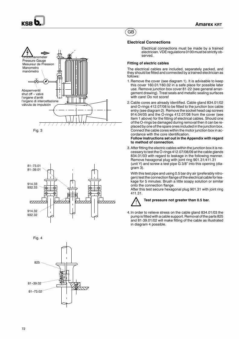
GB
Amarex KRT
72
Absperrventilshut off -- valvel‘organe d‘arrêtl‘organo di intercettazioneválvula de impulsión
DruckmanometerPressure GaugeMesureur de PressionManometromanómetro
Fig. 3
Fig. 4
81--73.0181--39.01
914.33932.33
914.32932.32
825
81--73.02
81--39.02
Electrical ConnectionsElectrical connections must be made by a trainedelectrician.VDEregulations0100mustbestrictlyob-served.
Fitting of electric cables
The electrical cables are included, separately packed, andthey should be fitted and connected by a trained electrician asfollows:1.Remove the cover (see diagram 1). It is advisable to keepthis cover 160.01/160.02 in a safe place for possible lateruse. Remove junction box cover 81-22 (see general arran-gement drawing). Treat seals andmetallic sealing surfaceswith care! Do not score!
2.Cable cores are already identified. Cable gland 834.01/02and O-rings 412.07/08 to be fitted to the junction box cableentry (see diagram2). Remove the socket head cap screws914.04/05 and the O-rings 412.07/08 from the cover (seeItem 1 above) for the fitting of electrical cables. Should oneof theO-rings be damaged during removal then it can be re-placedbyoneof thespareones included in the junctionbox.Connect the cable coreswithin themotor junction box in ac-cordance with the core identification.Follow instructions set out in the Appendix with regardto method of connection.
3.After fitting the electric cableswithin the junction box it is ne-cessary to test theO-rings 412.07/08/09 at the cable glands834.01/03 with regard to leakage in the following manner.Remove hexagonal plug with joint ring 901.31/411.31(unit Y) and screw a test pipe G 3/8” into this opening (dia-gram 3).
With this test pipe and using 0.5 bar dry air (preferably nitro-gen) test the connection flangeof theelectrical cable for lea-kage for 5 minutes. Brush a little soapy solution or similaronto the connection flange.After this test secure hexagonal plug 901.31 with joint ring411.31.
Test pressure not greater than 0.5 bar.
4. In order to relieve stress on the cable gland 834.01/03 thepump is fittedwithacable support.Removal of the parts 825and 81-39.01/02 will make fitting of the cable as illustratedin diagram 4 possible.
!

Montageanweisung -- Laufrad Auf-/AbziehvorrichtungFitting instructions -- Impeller fitting/withdrawing deviceInstruction de montage -- Dispositif de levée/de dépose de la roueInstruzioni di montaggio -- Dispositivo per montaggio/estrazione della giranteInstrucciones de montaje -- Dispositivo para montaje/desmontaje del rodete
Nr. 8.4
alle Motor-größenall motor sizestoutes les tail-les de moteurtutti i motoritodos los mo-tores
Amarex KRT
73
HydraulikhydraulicshydrauliqueIdraulicahidráulica
dL LaufraddL ImpellerdL RouedL GirantedL rodete
dW WelledW shaftdW ArbredW Albe-rodW eje
Abziehvorrichtungpull-off devicedispositifd‘enlévementEstrattoredispositivo paradesmontaje
Winkelschraubendreheroffset screwdriverMeuleuse d‘angleCacciavite angolaredestornillador acodado
Zapfensteck-schlüsselpin wrenchclé á ergotChiave fissa a tuboIlave de espiga
Drehstifttommy barBrocheSpinottoespiga de giro
DIN 911 AN 819 ZN 957
Ident-Nr./Ident no../No d‘identificationNr. di codice/No Ident
Ident-Nr./Ident no../No d‘identificationNr. di codiceNo Ident
Motorgrößen/motor sizes/taille dumoteurGrandezze deimotoreTamaño delmotor
Ident-Nr./Ident no../No d‘identificationNr. di codice/No Ident
Ident-Nr./Ident no../No d‘identificationNr. di codice/No Ident
E 150-400 M60x2 M16 19138912 17 00588089 alle Motor-größenall motor sizestoutes les tail-les de moteurtutti i motoritodos los mo-tores
E 100--401 M75x2 M20 19138913
F 100--401
E 150--400
K 150--500 41/30 00470123 20 00470192
K 200--330 17 00588089
E 200--401
K 200--401
K 250--370 206266
41/30 00470123 20 00470192
K 300--315
K 300--380 17 00588089 266108/178218
K 300--381 206/246108/178/218
K 200--501 M125x2 M24 19138914 60/40 00470126 25 00470193
K 300--400 M100x2 19138915
K 300--500 M125x2 19138914
K 350--420 M85x2 19138918
K 350--421
K 350--500 M125x2 19138914
K 500--540
K 600--520 M100x2 19138915
K 200--500 M125x2 19138914
K 200--501
K 300--400 M100x2 19138915
K 300--500 M125x2 19138914
K 350--420 M100x2 19138915
K 350--500 M125x2 19138914
K 350--630
K 500--540
K 500--640 M100x2 19138915
K 600--710 M125x2 19138914

Fig. 1
Fig. 2
Fig. 3 Fig. 4a Fig. 4b
260
412.06906
901.21 412.06550.23/931.01
412.06
906
412.06
901.21260550.23/931.01
2
1
2
1
SW2
SW1
SW2
SW3
4
dL M....
dW M....
Amarex KRT
74

D
GB
F
I
Amarex KRT
75
Montage/Demontage Laufrad
DiebenötigtenWerkzeuge sindder TabelleAbziehvorrichtung zuent-nehmen.das Auf--/Abziehen des Laufrades erfolgt mittels der in Fig. 3 gezeig-ten Spezial-Auf-/Abziehvorrichtung.
Demontage1.) Laufradbefestigung gemäß zugehörigerGesamtzeichnungAg-
gregat (Anhang 2) lösen.
-- Fig. 1: Laufradschraube 906 und O--Ring 412.06 entfernen.
-- Fig. 2: Zuerst Laufradkappe 260 mit O-Ring 412.06 entfer-nen. Danach 6kt.-Schraube 901.21 herausschrauben,Sicherungsblech 931.21 und Scheibe 550.23 abneh-men.
Abziehen des Laufrades Fig. 4b2.) Das Abziehen des Laufrades erfolgt durch die Spezial Auf-/Ab-
ziehvorrichtung. Hierzu in das Wellenende 6kt.-Schraube Teil 4einschraubenumBeschädigung desWellengewindes zu vermei-den.ZumAbziehendesLaufradesSpezial Auf-/Abziehvorrichtungan-bringen. Hierzu wird Teil 2 in das Laufrad eingeschraubt. DanachGewindebolzen Teil 1 einschrauben und Laufrad abziehen.
Montage Fig. 4a1.) Zum Aufziehen des Laufrades Teil 1 der Spezial-Auf-/Abziehvor-
richtung in das Wellende des Pumpenaggragates einschrauben.
2.) Danach Teil 2 durch Einschrauben auf dem Gewindebolzen Teil1 Laufrad aufziehen.
3.) Laufradbefestigung gemäß Fig.1/Fig. 2 montieren.
Fitting /Dismantling Impeller
The required tools are listed in the table ”dismantling equipment”.Fitting/Dismantlingof the impeller is carridoutbyusing thespecial toolshown in diagram 3.
Dismantling1.) Securing of the impeller is carried out in accordance with the ap-
propriate general drawing ”Pump unit” (Appendix 2)
-- Diagram 1: Remove impeller screw 906 and O-ring 412.06.
-- Diagram 2: First remove impeller hub cap. 260. thenunscrew the hexagonal screw 901.21. Lift offlock washer 931.21 and spacer 550.23.
Removing the impeller Diagram 4b2.) To remove the impeller use the special fitting/removal tool. A he-
xagonal screw, Part 4, should be screwed into the shaft end toavoid damage to the shaft thread.To remove the impeller, the special fitting/dismantling tool is atta-ched by screwing part 2 into the impeller. Then part 1, the threa-ded bolt, is screwed in and the impeller is removed.
Assembly/Fitting Diagram 4a1.) The impeller is mounted by screwing part 1 of the special assem-
bly/dismantling tool into the shaft end of the pump unit.
2.) Thenpart 2 is screwed into the threadedbolt, part 1, and the impel-ler is mounted.
3.) Fitting of the impeller is carried out in accordance withdiagram 1/diagram 2.
Montage/démontage de la roue
Pour les outils nécessaires se reporter au tableau ”démonte -- roue”.Lemontage et le démontage de la roue se font aumoyen du dispositifspécial de montage et de démontage.
Démontage1.) Desserrer la fixationde la roueconformémentaupland’ensemble
”groupe moto -- pompe” correspondant (annexe 2).
-- Fig. 1 : Enlever la vis 906 et le joint torique 412.06.
-- Fig. 2 : Après avoir retiré le cache -- roue 260 avec le jointtorique 412.06., dévisser la vis à six pans 901.21,la plaque d’arrêt 931.21 et la rondelle 550.23.
Démontage de la roue fig. 4b2.) Le démontage de la roue se fait au moyen du démonte -- roue
spécial. Pour cela visser la vis à six pans, rep. 4 dans le boutd’arbre afin d’éviter un endomma -- gement du filetage de l’arbre.Pour le démontage de la roue mettre en place le démonte -- rouespécial. Pour ce faire, visser la pièce rep. 2 dans la roue. Ensuitevisser le boulon fileté, rep. 1 et retirer la roue.
Montage fig. 4a1.) Pour le montage de la roue, visser la pièce, rep. 1 du démonte --
roue spécial dans le bout d’arbre du groupe moto -- pompe.
2.) Ensuite visser la pièce 2 sur le boulon fileté, rep. 1 et monter laroue.
3.) Monter la fixation de la roue suivant fig. 1 et 2.
Montaggio/Smontaggio della girante
Gli utensili necessari sono indicati nella tabelle relativa al dispositivodi estrazione.Al montaggio ed all’estrazione della girante si provvede con l’utensilespeciale di montaggio ed estrazione mostrato allaFig. 3.
Smontaggio1.) Svitare il fissaggio della girante come da disegno in
sezione del gruppo (Appendice 2)-- Fig.1: Rimuovere la vite controgirante 906 e l’O--Ring
412.06.-- Fig.2: Rimuovere anzitutto il cappellotto 260 con
l’O--Ring 412.06. Svitare quindi la vite a testaesagonale 901.21, rimuovere il lamierino disicurezza 931.01 e la rondella 550.23.
Estrazione della girante Fig. 4b2.) La girante si estrae con il dispositivo speciale di montaggio e di
estrazione. A questo scopo si deve avvitare nell’estremità dell’al-bero la vite a testa esagonale Pos. 4, per evitare di danneggiarnela filettatura. Per sfilare la girante montare il dispositivo specialedi estrazione. A questo scopo si avvita nella girante il particolarePos. 2. Quindi si avvita lo spinotto filettato Pos. 1 e si estrae la gi-rante.
Montaggio Fig. 4a1.) Per montare la girante si deve avvitare nell’estremità
dell’albero della pompa l’utensile speciale di montaggio edestrazione Pos. 1.
2.) Montare quindi la girante avvitando il particolare Pos. 2sullospinotto filettato Pos. 1.3.) Montare il fissaggio della girante come da Fig.1/Fig.2
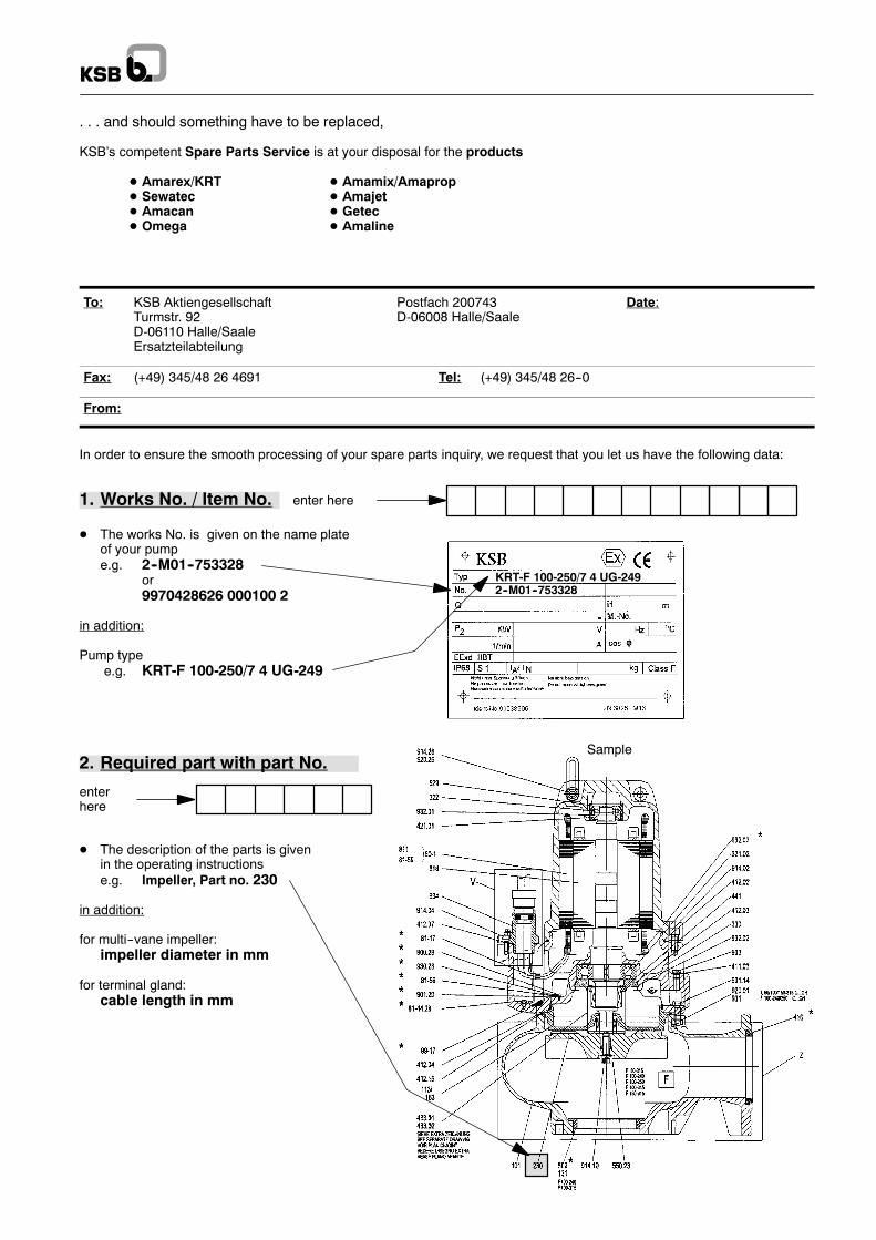
1. Works No. / Item No.
KRT-F 100-250/7 4 UG-2492--M01--753328
enter here
2. Required part with part No.
enterhere
Sample
. . . and should something have to be replaced,
KSB’s competent Spare Parts Service is at your disposal for the products
D Amarex/KRT D Amamix/AmapropD Sewatec D AmajetD Amacan D GetecD Omega D Amaline
To: KSB Aktiengesellschaft Postfach 200743 Date:Turmstr. 92 D-06008 Halle/SaaleD-06110 Halle/SaaleErsatzteilabteilung
Fax: (+49) 345/48 26 4691 Tel: (+49) 345/48 26--0
From:
In order to ensure the smooth processing of your spare parts inquiry, we request that you let us have the following data:
D The works No. is given on the name plateof your pumpe.g. 2--M01--753328
or9970428626 000100 2
in addition:
Pump typee.g. KRT-F 100-250/7 4 UG-249
D The description of the parts is givenin the operating instructionse.g. Impeller, Part no. 230
in addition:
for multi--vane impeller:impeller diameter in mm
for terminal gland:cable length in mm

Amarex KRT

Amarex KRT

Amarex KRT

2553.807-10
09.12.2004
Subjecttomodificationwithoutnotice
KSB AktiengesellschaftP.O. Box 200743 � 06008 Halle (Saale) � Turmstraße 92 � 06110 Halle (Germany)Tel. +49 (345) 48 26 0 � Fax +49 (345) 48 26 46 99 � www.ksb.com
Amarex KRT


![Amarex KRT...Amarex KRT, n = 1450 / 960 t/min, roue E 50 Q [US.gpm]100 200 300 400 500 1000 2000 3000 4000 40 50 Q [IM.gpm]100 200 300 400 500 1000 2000 3000 3 4 5 Q [l/s] 10 20 30](https://static.fdocuments.net/doc/165x107/5e280b3a97c4ea597029c00c/amarex-krt-amarex-krt-n-1450-960-tmin-roue-e-50-q-usgpm100-200-300.jpg)


