Determinacion actividad serica creatin quinaza aspartato ...

Product Specification Serica-SR4W035-PS-1.0 Page 1
Antennas for Wireless M2M Applications
1. Features
Antenna for 2.4GHz applications
Bluetooth, Wi-Fi, ZigBee, ISM.
Maintains high performance on device: DFI (Designed for Integration)
Ultra-low profile innovative design.
SMD mounting
Supplied on Tape and Reel
Automotive temperature rating.
2. Description Serica is intended for use with 2.4GHz applications. The antenna only requires a small ground plane. It is ideal for single and MIMO antenna systems. This product specification shows the performance of the antenna over the frequency range 2.4 – 2.5GHz.
3. Applications
Wearable devices
Medical equipment
Tablets
Network Devices
MIMO Systems
IP Cameras Access Points
Serica 2.4GHz Antenna Part No. SR4W035 lamiiANT ® Product Specification

Serica Part No. SR4W035
Antennas for Wireless M2M Applications
Product Specification Serica-SR4W035-PS-1.0 Page 2
4. Part Number
Serica: SR4W035
5. General Data
6. RF Characteristics
Product name Serica
Part Number SR4W035
Frequency 2.4 – 2.5 (GHz)
Polarization Linear
Operating temperature -40°C to140°C
Environmental Condition Test ISO16750-4 5.1.1.1/5.1.2.1/5.3.2
Impedance with matching 50 Ω
Weight <1g
Antenna type SMD
Dimensions 6.0 x 4.0 x 0.4 (mm)
2400 - 2500 MHz Conditions
Peak gain 3.50dBi
All data measured on Antenova’s evaluation PCB Part No. SR4W035-EVB-1
Average gain (Linear) -1.50dBi
Average efficiency >65%
Maximum return loss -10.0dB
Maximum VSWR 1.85:1

Serica Part No. SR4W035
Antennas for Wireless M2M Applications
Product Specification Serica-SR4W035-PS-1.0 Page 3
7. RF Performance
7.1 Return Loss
7.2 VSWR
Serica Part No. SR4W035
Antennas for Wireless M2M Applications
Product Specification Serica-SR4W035-PS-1.0 Page 4
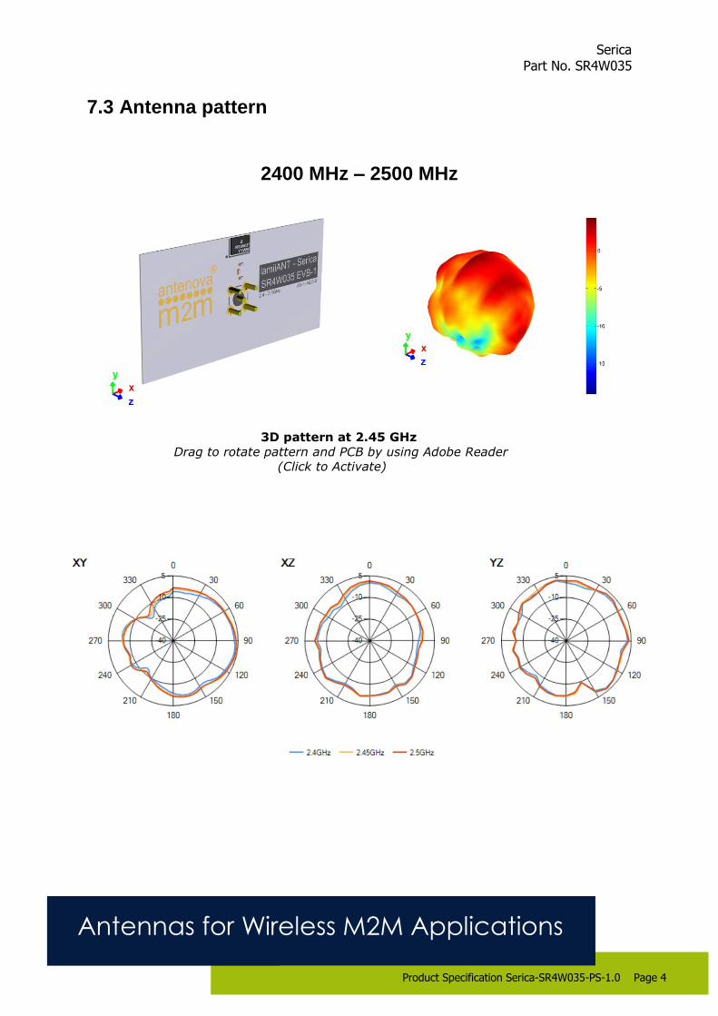
7.3 Antenna pattern
2400 MHz – 2500 MHz
3D pattern at 2.45 GHz
Drag to rotate pattern and PCB by using Adobe Reader
(Click to Activate)

Serica Part No. SR4W035
Antennas for Wireless M2M Applications
Product Specification Serica-SR4W035-PS-1.0 Page 5
8. Antenna Dimensions
Bottom Side Dimensions
L W H
Length Width Height
6.0 ±0.1 4.0 ±0.1 0.4 +0.1 -0.0
All Dimensions in (mm)

Serica Part No. SR4W035
Antennas for Wireless M2M Applications
Product Specification Serica-SR4W035-PS-1.0 Page 6
10.0 Schematic symbol and Pin definition
The circuit symbol for the antenna is shown below. The antenna has 6 pins with only two as functional. All other pins are for mechanical strength.
9.0 Antenna footprint The recommended host PCB footprint is below.
6 copper pads all 1.0 x 1.0 (mm)
Pin Description
2 Feed
3,4,6 Return/GND
1,5 Not used (Mechanical only)
Serica Schematic Symbol
1 2 3
4 5 6

Serica Part No. SR4W035
Antennas for Wireless M2M Applications
Product Specification Serica-SR4W035-PS-1.0 Page 7
11. Electrical Interface
11.1 Transmission Line All transmission lines should be designed to have a characteristic impedance of 50Ω. • The length of the transmission lines should be kept to a minimum. • Any other parts of the RF system like transceivers, power amplifiers, etc, should also be designed to have an impedance of 50 Ω.
Once the material for the PCB has been chosen (PCB thickness and dielectric constant), a coplanar transmission line can easily be designed using any of the commercial software packages for transmission line design. For the chosen PCB thickness, copper thickness and substrate dielectric constant, the program will calculate the appropriate transmission line width and gaps on either side of the track, so the characteristic impedance of the co-planar transmission is 50 Ω.
11.2 Matching Circuit
The antenna requires a matching circuit that must be optimized for each product. The matching circuit will require up to five components and the following circuit should be designed into the host PCB. Not all components may be required but should be included as a precaution. The matching network must be placed close to the antenna feed to ensure it is more effective in tuning the antenna.

Serica Part No. SR4W035
Antennas for Wireless M2M Applications
Product Specification Serica-SR4W035-PS-1.0 Page 8
12.0 Antenna Integration Guide
12.1 Antenna Placement Whichever size host PCB is used, the antenna should ideally be placed on the host PCB’s longest edge at the centre.
Where the centre is not a viable option, the antenna can be placed offset on the PCB to within the limits shown below. A minimum of 6mm from either PCB edge should be observed. Where possible this distance should be greater than 6mm.

Serica Part No. SR4W035
Antennas for Wireless M2M Applications
Product Specification Serica-SR4W035-PS-1.0 Page 9
12.2 Host PCB Layout The footprint and clearance of the host PCB must meet the antenna specification. An example of the PCB layout, below, shows the antenna footprint with clearance. Pins 3, 4 and 6 (GND) are shown directly connecting to the GND with the shortest route. The feed (Pin 2) connects to the matching circuit close to the antenna.
Example host layout

Serica Part No. SR4W035
Antennas for Wireless M2M Applications
Product Specification Serica-SR4W035-PS-1.0 Page 10
12.3 Host PCB Clearance
The diagram below shows the antenna footprint and clearance through all layers on the PCB. Only the antenna pads and connections to feed and GND are present within this clearance area. The clearance area required is 6.0 x 4.0 (mm).
The clear-out area is simply defined as the same size as the antenna. No additional clearance is required.
Clearance area

Serica Part No. SR4W035
Antennas for Wireless M2M Applications
Product Specification Serica-SR4W035-PS-1.0 Page 11
14.0 Reference Board
The reference board has been designed for the purpose of evaluating SR4W035 and includes an SMA female connector.
SR4W035-EVB-1 Evaluation Board
To order a reference board contact [email protected]. Please state if a single antenna or two antenna EVB is required.
Serica Part No. SR4W035
Antennas for Wireless M2M Applications
Product Specification Serica-SR4W035-PS-1.0 Page 12
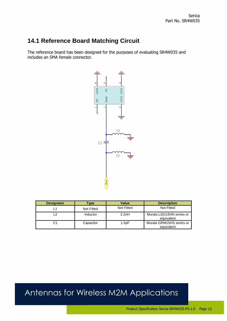
14.1 Reference Board Matching Circuit
The reference board has been designed for the purposes of evaluating SR4W035 and includes an SMA female connector.
Designator Type Value Description
L1 Not Fitted Not Fitted Not Fitted
L2 Inductor 2.2nH Murata LQG15HN series or equivalent
C1 Capacitor 1.5pF Murata GRM15HS series or equivalent
Serica Part No. SR4W035
Antennas for Wireless M2M Applications
Product Specification Serica-SR4W035-PS-1.0 Page 13
15. Soldering This antenna is suitable for lead free soldering. The reflow profile should be adjusted to suit the device, oven and solder paste, while observing the following conditions:
The maximum temperature should not exceed 240 ºC.
However for lead free soldering, a maximum temperature of 255 ºC for no more than 20 seconds is permitted.
The antenna should not be exposed to temperatures exceeding 120 ºC more than 3 times during the soldering process.
16. Hazardous Material Regulation Conformance The antenna has been tested to conform to RoHS requirements. A certificate of conformance is available from Antenova M2M’s website.
17. Packaging
17.1 Optimal Storage Conditions
Temperature -10ºC to 40ºC
Humidity Less than 75% RH
Shelf life 24 Months
Storage place Away from corrosive gas and direct sunlight
Packaging Reels should be stored in unopened sealed manufacturer’s plastic packaging.
Note: Storage of open reels of antennas is not recommended due to possible oxidization
of pads on antennas. If short term storage is necessary, then it is highly recommended that the bag containing the antenna reel is re-sealed and stored in like storage conditions
as in above table.

Serica Part No. SR4W035
Antennas for Wireless M2M Applications
Product Specification Serica-SR4W035-PS-1.0 Page 14
17.2 Tape Characteristics
Ko Ao Bo P0 P1 P2
0.95 ± 0.1 4.20 ± 0.1 6.20 ± 0.1 4.00 ± 0.1 8.00 ± 0.1 2.00 ± 0.1
E F W
1.75 ± 0.1 7.50 ± 0.15 12.00 ± 0.3
Dimensions in mm
Notes: 1) 10 sprocket hole pitch cumulative tolerance ±0.2
2) Camber not to exceed 1mm in 100mm
3) Ao and Bo measured on a plane 0.1mm above the bottom of the pocket
4) Ko measured from a plane on the inside bottom of the pocket to the top surface of the carrier
Serica Part No. SR4W035
Antennas for Wireless M2M Applications
Product Specification Serica-SR4W035-PS-1.0 Page 15
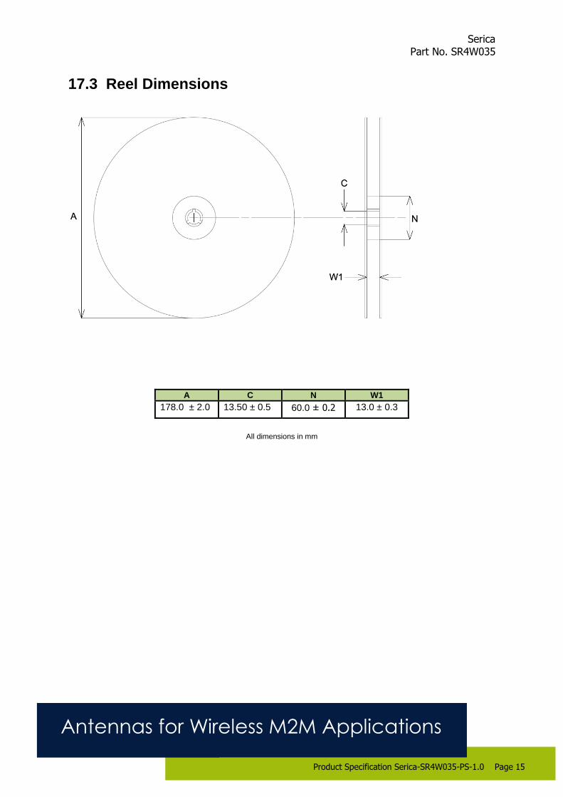
17.3 Reel Dimensions
A C N W1
178.0 ± 2.0 13.50 ± 0.5 60.0 ± 0.2 13.0 ± 0.3
All dimensions in mm

Serica Part No. SR4W035
Antennas for Wireless M2M Applications
Product Specification Serica-SR4W035-PS-1.0 Page 16
17.4 Box Dimensions
Width (W)
Breadth (B)
Thickness (H)
203mm 188mm 40mm
17.5 Bag Properties Reels are supplied in protective plastic packaging.
17.6 Reel Label Information
Antenova Limited
4F, No 324, Sec 1, Nei-Hu Road Nei-Hu District, Taipei 11493, Taiwan, ROC [email protected] / www.antenova-m2m.com Description: Serica Part number: SR4W035 Quantity: 1,000 Date Code: YYWW
Manufacturer’s code number: lamiiANT®
60mm
90mm
60mm

Serica Part No. SR4W035
Antennas for Wireless M2M Applications
Product Specification Serica-PS-SR4W035-1.0 Release date March 2017 Page 17
www.antenova-m2m.com
Corporate Headquarters
Antenova Limited
2nd
Floor Titan Court
3 Bishop Square
Hatfield
AL10 9NA
UK
Tel: +44 1223 810600
Email: [email protected]
North America Headquarters
Antenova Limited
100 Brush Creek Road
Suite 103, Santa Rosa
California 95404,
USA
Tel: +1 707 890 5202
Email: [email protected]
Asia Headquarters
Antenova Asia Limited
4F, No. 324, Sec. 1, Nei-Hu Road
Nei-Hu District
Taipei 11493
Taiwan, ROC
Tel: +886 (0) 2 8797 8630
Fax: +886 (0) 2 8797 6890
Email: [email protected]
Copyright® Antenova Ltd. All Rights Reserved. Antenova ®, Antenova M2M ®, gigaNOVA ®, the Antenova
product family names, and the Antenova and Antenova M2M logos are trademarks and/or registered trademarks
of Antenova Ltd. Any other names and/or trademarks belong to their respective companies.
The materials provided herein are believed to be reliable and correct at the time of printing. Antenova does not
warrant the accuracy or completeness of the information, text, graphics or other items contained within this
information. Antenova further assumes no responsibility for the use of this information, and all such information
shall be entirely at the user’s risk.