
Serial I/O SST128P Expandable Adapter Hardware Installation Guide...
56
37L1461 PN 560156/A October, 1998 OPTIONS by IBM Serial I/O SST128P Expandable Adapter Hardware Installation Guide
Transcript of Serial I/O SST128P Expandable Adapter Hardware Installation Guide...
37L1461
PN 560156/AOctober, 1998
OPTIONS by IBM
Serial I/O SST128P Expandable Adapter
HardwareInstallation Guide

IBM Serial I/O 128P Expandable Subsystemii
ManualOrganization
This manual is comprised of five chapters and two appendices.
Chapter 1 OverviewChapter 1 describes the IBM Serial I/O ExpandableSubsystem components and their various configura-tions.
Chapter 2 Adapter Installation & SetupChapter 2 describes the installation of the Serial I/OAdapters and use of the host power "Y" cable.
Chapter 3 Serial I/O Port Module InstallationChapter 3 describes how to install the ExpansionModules, the Expansion Bus Cabling, installing thePS-4 Power Supply and defines the module LEDs.
Chapter 4 Serial I/O Multiplexer InstallationChapter 4 describes the installation of the ClusterMultiplexers, component wall mounting, PowerAdapters and the Multiplexer Link Cable.
Chapter 5 Serial I/O Port to Device CablingChapter 5 describes the cabling options that workwith the Serial I/O Expandable Subsystem.
Appendix A Power Defaults & OptionsAppendix A provides a description of the PowerStrap default and optional Power Strap configura-tions for Serial I/O Adapters.
Appendix B Help and Service InformationAppendix B describes the steps you would follow toreceive technical support and to report problems withthis documentation.
Index
iii
Contents
Hardware Installation Guide .................................................... iManual Organization........................................................... iiContents ............................................................................. iii
Overview ............................................................................... 1-1PCI Adapters ................................................................... 1-1Expansion Modules ......................................................... 1-3Expansion Bus Cables..................................................... 1-6Power Options ................................................................. 1-8
Serial I/O Adapter Installation & Setup ............................... 2-1PCI System Setup ........................................................... 2-1Software Installation ........................................................ 2-1Adapter Installation .......................................................... 2-1Host Power “Y” Cable ...................................................... 2-2
Serial I/O Port Module Installation ...................................... 3-1Installing Expansion Modules .......................................... 3-2Expansion Bus Cabling .................................................... 3-4Installing the PS-4 Power Supply ..................................... 3-7Module LEDs ................................................................... 3-8
Serial I/O Multiplexer Installation ........................................ 4-1Cluster Multiplexers ......................................................... 4-2Wall Mounting .................................................................. 4-2Power Adapters ............................................................... 4-2Multiplexer Link Cable ..................................................... 4-3

IBM Serial I/O 128P Expandable Subsystemiv
Serial I/O Port To Device Cabling........................................ 5-1PM16-DB and CMX16-DB Port Pinouts ........................... 5-1Device Wiring ..................................................................5-2Four Wire Connection ...................................................... 5-3Seven Wire Connection ...................................................5-4Personal Computer Serial Port ........................................ 5-5PM16-RJ and CMX16-RJ Port Pinouts ............................5-6Modular Cables ...............................................................5-9Modular Adapters .......................................................... 5-10
Power Defaults & Options .................................................. A-1Optional Power Configuration ......................................... A-2Default Power Configuration ........................................... A-2
Help and Service Information ............................................. B-1Preparing To Call Technical Support .............................. B-1Placing the Call to IBM .................................................... B-2Product Warranty ............................................................ B-3The IBM Warranty for Machines ..................................... B-3Statement of Limited Warranty ....................................... B-3Production Status ........................................................... B-3Warranty Service ............................................................ B-4Extent of Warranty .......................................................... B-5Trademarks .................................................................... B-6Limitation of Liability ........................................................ B-6Electronic Emission Notices ........................................... B-7
Index .............................................................................. Index-1
Overview 1-1
The IBM Serial I/O Expandable I/O Subsystem is a High-speedSerial Communications Multiple Port product. It consists of severaldifferent modular components configured in a variety ofcombinations to satisfy most applications. The various componentsare:
l Adapter
l Expansion Modules
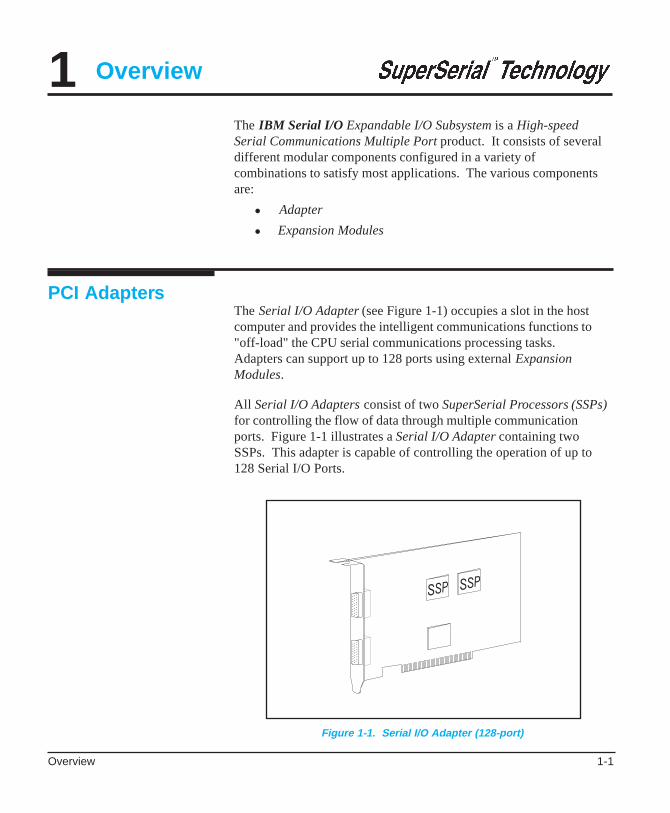
The Serial I/O Adapter (see Figure 1-1) occupies a slot in the hostcomputer and provides the intelligent communications functions to"off-load" the CPU serial communications processing tasks.Adapters can support up to 128 ports using external ExpansionModules.
All Serial I/O Adapters consist of two SuperSerial Processors (SSPs)for controlling the flow of data through multiple communicationports. Figure 1-1 illustrates a Serial I/O Adapter containing twoSSPs. This adapter is capable of controlling the operation of up to128 Serial I/O Ports.
1
PCI Adapters
Overview
Figure 1-1. Serial I/O Adapter (128-port)
IBM Serial I/O 128P Expandable Subsystem Hardware Installation Manual1-2
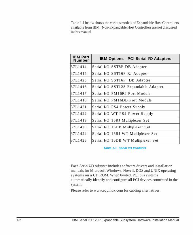
Table 1.1 below shows the various models of Expandable Host Controllersavailable from IBM. Non-Expandable Host Controllers are not discussedin this manual.
Each Serial I/O Adapter includes software drivers and installationmanuals for Microsoft Windows, Novell, DOS and UNIX operatingsystems on a CD ROM. When booted, PCI bus systemsautomatically identify and configure all PCI devices connected in thesystem.
Please refer to www.equinox.com for cabling alternatives.
Table 1-1 Serial I/O Products
IBM PartNumber IBM Options - PCI Serial I/O Adapters
37L1414 Seria l I/O SST8P DB Adapter
37L1415 Seria l I/O SST16P RJ Adapter
37L1423 Seria l I/O SST16P DB Adapter
37L1416 Seria l I/O SST128 Expandable Adapter
37L1417 Seria l I/O PM16RJ Port Module
37L1418 Seria l I/O PM16DB P ort Module
37L1421 Seria l I/O PS4 Power Supply
37L1422 Seria l I/O WT PS4 Power Supply
37L1419 Seria l I/O 16RJ Multip lexer Set
37L1420 Seria l I/O 16DB Multip lexer S et
37L1424 Seria l I/O 16RJ WT Multip lexer Set
37L1425 Seria l I/O 16DB W T Multip lexer S et
Overview 1-3
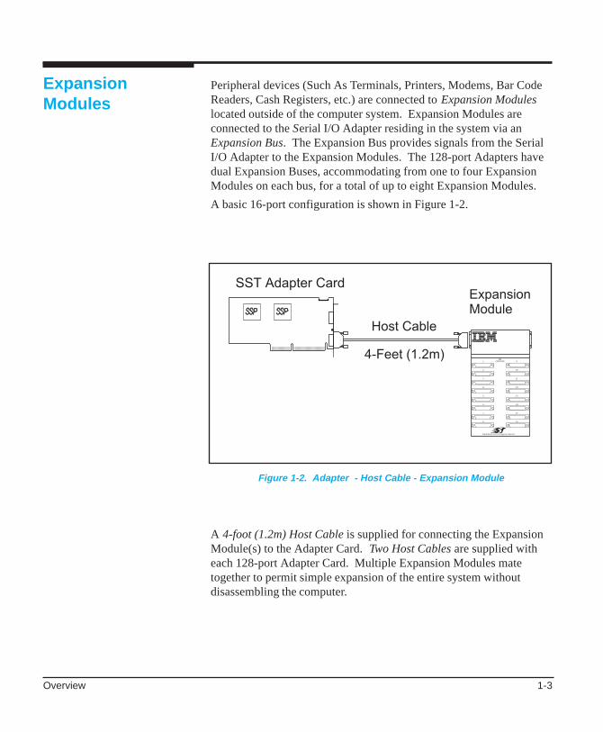
Peripheral devices (Such As Terminals, Printers, Modems, Bar CodeReaders, Cash Registers, etc.) are connected to Expansion Moduleslocated outside of the computer system. Expansion Modules areconnected to the Serial I/O Adapter residing in the system via anExpansion Bus. The Expansion Bus provides signals from the SerialI/O Adapter to the Expansion Modules. The 128-port Adapters havedual Expansion Buses, accommodating from one to four ExpansionModules on each bus, for a total of up to eight Expansion Modules.
A basic 16-port configuration is shown in Figure 1-2.
ExpansionModules
A 4-foot (1.2m) Host Cable is supplied for connecting the ExpansionModule(s) to the Adapter Card. Two Host Cables are supplied witheach 128-port Adapter Card. Multiple Expansion Modules matetogether to permit simple expansion of the entire system withoutdisassembling the computer.
Figure 1-2. Adapter - Host Cable - Expansion Module
IBM Serial I/O 128P Expandable Subsystem Hardware Installation Manual1-4
Multiplexer InterfaceModules
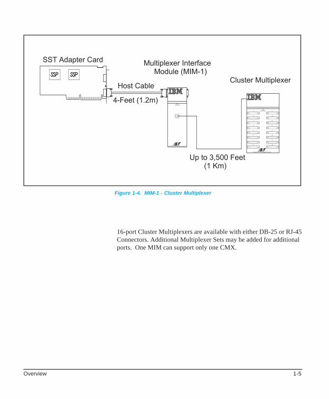
Clusters of devices may be connected within a radius of 3,500 feet(1Km) to the Adapter using Multiplexer Set which includesMultiplexer Interface Modules (MIM), Cluster Multiplexers (CMX)and Power Supply. (see Figure 1-4). In this application a 16-portCluster Multiplexer is located near the user devices and a low-costtwo-twisted-pair link (category 2 or above UTP) cable is run back tothe Multiplexer Interface Module. Cluster Multiplexers are ideal fordistributing devices in, as an example, a multi-building campus facility.
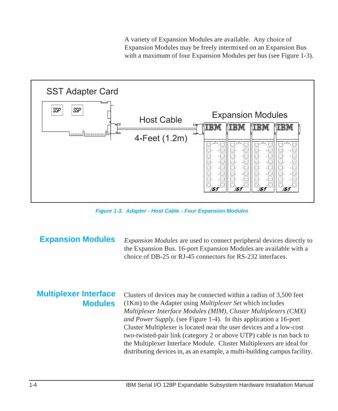
A variety of Expansion Modules are available. Any choice ofExpansion Modules may be freely intermixed on an Expansion Buswith a maximum of four Expansion Modules per bus (see Figure 1-3).
Expansion Modules are used to connect peripheral devices directly tothe Expansion Bus. 16-port Expansion Modules are available with achoice of DB-25 or RJ-45 connectors for RS-232 interfaces.
Expansion Modules
Figure 1-3. Adapter - Host Cable - Four Expansion Modules
Overview 1-5
16-port Cluster Multiplexers are available with either DB-25 or RJ-45Connectors. Additional Multiplexer Sets may be added for additionalports. One MIM can support only one CMX.
Figure 1-4. MIM-1 - Cluster Multiplexer
IBM Serial I/O 128P Expandable Subsystem Hardware Installation Manual1-6
Expansion BusCables
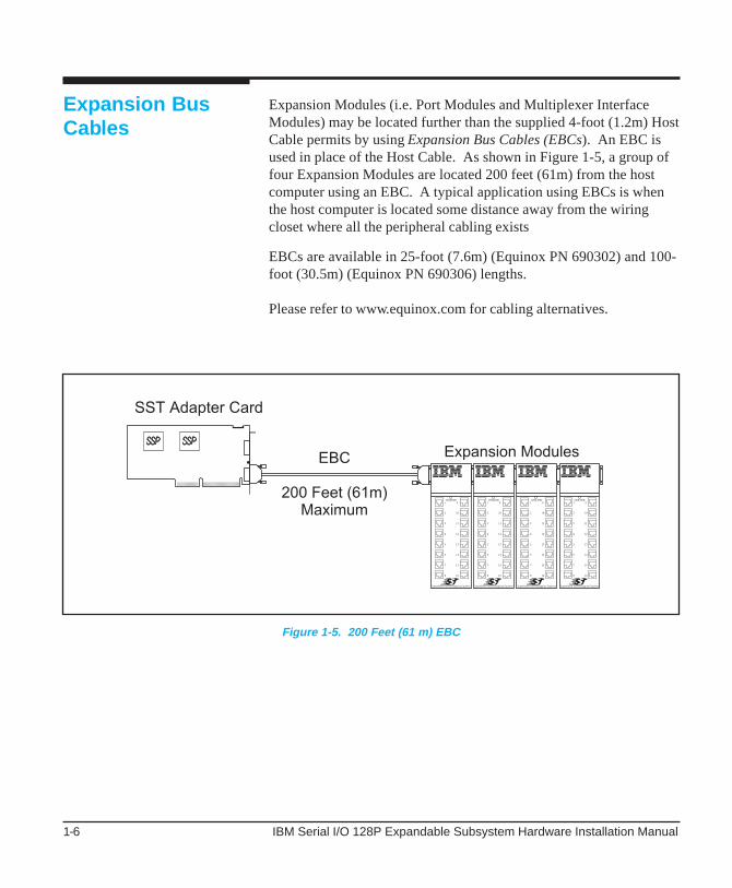
Expansion Modules (i.e. Port Modules and Multiplexer InterfaceModules) may be located further than the supplied 4-foot (1.2m) HostCable permits by using Expansion Bus Cables (EBCs). An EBC isused in place of the Host Cable. As shown in Figure 1-5, a group offour Expansion Modules are located 200 feet (61m) from the hostcomputer using an EBC. A typical application using EBCs is whenthe host computer is located some distance away from the wiringcloset where all the peripheral cabling exists
EBCs are available in 25-foot (7.6m) (Equinox PN 690302) and 100-foot (30.5m) (Equinox PN 690306) lengths.
Please refer to www.equinox.com for cabling alternatives.
Figure 1-5. 200 Feet (61 m) EBC
Overview 1-7
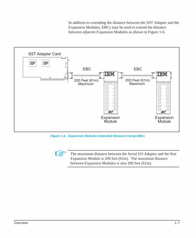
In addition to extending the distance between the SST Adapter and theExpansion Modules, EBCs may be used to extend the distancebetween adjacent Expansion Modules as shown in Figure 1-6.
☞ The maximum distance between the Serial I/O Adapter and the firstExpansion Module is 200 feet (61m). The maximum distancebetween Expansion Modules is also 200 feet (61m).
Figure 1-6. Expansion Modules Extended Distance Using EBCs

IBM Serial I/O 128P Expandable Subsystem Hardware Installation Manual1-8
In simple configurations, the host Adapter supplies power to all PortExpansion Modules and Multiplexer Interface Expansion Modulesattached to the Expansion Bus via the supplied 4-foot (1.2m) Host Cable(see Figure 1-7). Power is provided by the Adapter and is passed fromthe left to right through each directly mated module.
Power Options
Host power is available to the Expansion Modules only when the4-foot (1.2m) Host Cable is installed and Expansion Modules aremated directly together.
☞
☞ Expansion Modules may draw power from the host computer throughthe 4-foot (1.2m) Host Cable.
Figure 1-7. Mated Expansion Modules Draw Power from Host

Overview 1-9
The Expansion Modules attached to the Expansion Bus (not host bus)Cables must be externally powered using a separate power supply. Ifan EBC is installed, this optional power supply is purchasedseparately and must be connected to the first (left most) module on theExpansion Bus (see Figure 1-8).
By connecting the PS-4 Power Supply to the first Module, power is nolonger drawn from the host computer. All Expansion Modulesdirectly mated to one another from the first Module are suppliedpower from the PS-4. The PS-4 can supply power for up to fourExpansion Modules.
Figure 1-8. PS-4 Supplying Power to Expansion Modules

IBM Serial I/O 128P Expandable Subsystem Hardware Installation Manual1-10
Cluster Multiplexers draw power from a Power Adapter supplied inthe Multiplexer Set, which plugs directly into any convenient walloutlet (see Figure 1-10).
When Expansion Bus Cables are used between Expansion Modules, aPS-4 Power Supply is required for each Module as shown in Figure 1-9.
Figure 1-9. Individual PS-4s Provide Power to Modules Separated by EBCs
Figure 1-10. Cluster Multiplexer Draws Power From Power Adapter

Overview 1-11
Figure 1-11 illustrates a Serial I/O Subsystem using the maximumnumber of ports (128) for an Adapter.
☞ MIM-1 Module draws power from the Serial I/O Adapter, or a PS-4Power Supply.
Figure 1-11. Maximum Number of Ports Per Adapter (128)
IBM Serial I/O 128P Expandable Subsystem Hardware Installation Manual1-12
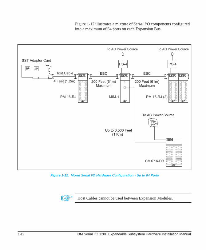
Figure 1-12 illustrates a mixture of Serial I/O components configuredinto a maximum of 64 ports on each Expansion Bus.
Figure 1-12. Mixed Serial I/O Hardware Configuration - Up to 64 Ports
☞ Host Cables cannot be used between Expansion Modules.
Serial I/O SST 128P Adapter Installation & Setup 2-1
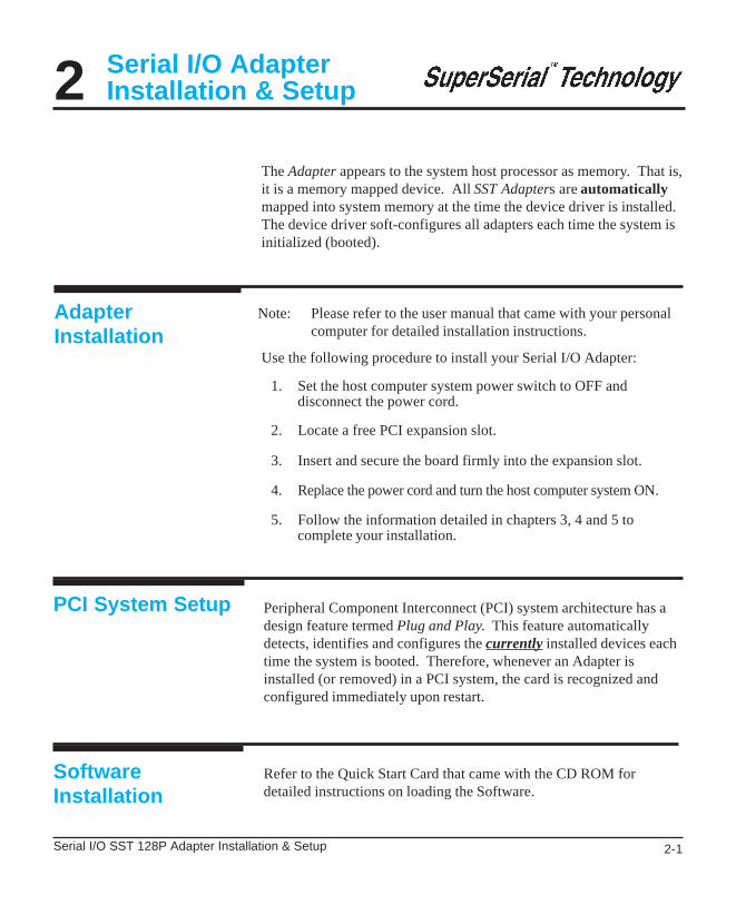
Serial I/O AdapterInstallation & Setup
AdapterInstallation
2The Adapter appears to the system host processor as memory. That is,it is a memory mapped device. All SST Adapters are automaticallymapped into system memory at the time the device driver is installed.The device driver soft-configures all adapters each time the system isinitialized (booted).
Note: Please refer to the user manual that came with your personalcomputer for detailed installation instructions.
Use the following procedure to install your Serial I/O Adapter:
1. Set the host computer system power switch to OFF anddisconnect the power cord.
2. Locate a free PCI expansion slot.
3. Insert and secure the board firmly into the expansion slot.
4. Replace the power cord and turn the host computer system ON.
5. Follow the information detailed in chapters 3, 4 and 5 tocomplete your installation.
PCI System Setup Peripheral Component Interconnect (PCI) system architecture has adesign feature termed Plug and Play. This feature automaticallydetects, identifies and configures the currently installed devices eachtime the system is booted. Therefore, whenever an Adapter isinstalled (or removed) in a PCI system, the card is recognized andconfigured immediately upon restart.
Refer to the Quick Start Card that came with the CD ROM fordetailed instructions on loading the Software.
SoftwareInstallation

IBM Serial I/O 128P Expandable Subsystem Hardware Installation Manual2-2
Host Power “Y”Cable
The Host Power “Y” Cable is included with all 128 port ExpandableAdapters. This cable provides power from the host power supply forModules connected to the second Expansion Bus. Connect the hostpower “Y” cable as described below:
• If necessary, remove all power from the computer. (Turnpower switch OFF and unplug main power cord.)
• If necessary, remove (or lift up) the host computer systemchassis cover.
• Locate a power supply cable connected to a component (e.g.floppy disk drive) in your host computer system. If possible,select the component nearest the location of the powerconnector on the adapter.
• Remove the host power supply cable connector plug from theselected host computer system component power connectorsocket.
• Connect the removed host power supply cable connector plugto a mating connector socket on the host power “Y” cablesupplied by IBM.
• Connect the host power “Y” cable connector plug to the hostcomputer system component where the power supply cableconnector plug was removed.
• Connect the other host power “Y” cable connector plug to thepower connector socket on the 128-port Adapter.
• Replace the chassis cover (or close) and restore power to thehost computer system.

Serial I/O Port Module Installation 3-1
Serial I/O PortModule Installation
Serial I/O Port Modules are used to connect peripheral devices directlyto the Expansion Bus. Port Modules are available with a choice of DB-25 or RJ-45 connectors. Figure 3-1 illustrates two types of Serial I/OPort Modules and the MIM-1. The MIM-1 is used to connect theCluster Multiplexer (CMX) to the Expansion Bus.
In the following paragraphs, references to Expansion Modules includesthe Serial I/O Port Modules and MIM-1.
3
Figure 3-1. Serial I/O Expansion Modules

IBM Serial I/O 128P Expandable Subsystem Hardware Installation Manual3-2
InstallingExpansionModules
Up to four SST Expansion Modules may be grouped together andconnected to an adapter card via an Expansion Bus. The Expansion Busconnector may be either a 4-foot (1.2m) Host Cable or an EBC.
Included with each Expansion Module are two L-shaped couplerbrackets and twelve screws (8 black-anodized and 4 nickel-plated).Group the Modules by mating them together as shown in Figure 3-2.
Attach the coupler brackets as indicated in Figure 3-3.
Figure 3-2. Mating Two Expansion Modules

Serial I/O Port Module Installation 3-3
Also included with each Expansion Module are two wall mountingbrackets and four screws. Attach the mounting brackets to theappropriate modules and secure them to a wall as shown in Figure 3-3.
Attach one bracket on the top and one bracket on the bottom atthe opposite side of the Module when mounting a single Moduleto a wall
☞ Use the nickel-plated screws to secure the coupler brackets to theback of the Expansion Modules and the black-anodized screws tosecure the coupler brackets to the top and bottom of the expansionmodules.
☞
Figure 3-3. Coupling and Surface Mounting Two PM16-DB Port Modules

IBM Serial I/O 128P Expandable Subsystem Hardware Installation Manual3-4
Expansion BusCabling
Connect Modules to the host computer using the supplied host cableor optional Expansion Bus cables provided by Equinox. Referring toFigure 3-4, connect the cable for ports 1 through 64 to the lowerconnector of the adapter card and the cable for ports 65 through 128to the upper connector.
Figure 3-4. EBC Port Assignments
Serial I/O Port Module Installation 3-5
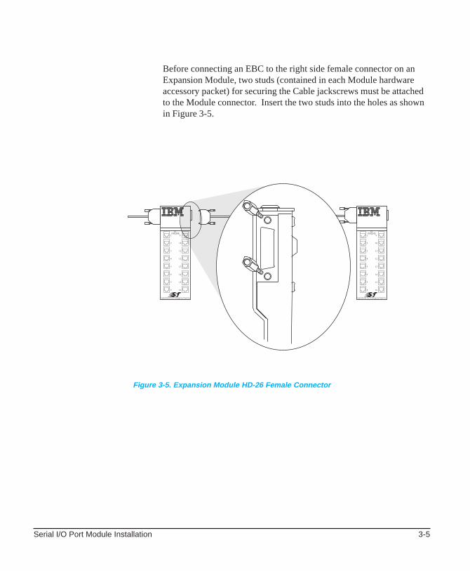
Before connecting an EBC to the right side female connector on anExpansion Module, two studs (contained in each Module hardwareaccessory packet) for securing the Cable jackscrews must be attachedto the Module connector. Insert the two studs into the holes as shownin Figure 3-5.
Figure 3-5. Expansion Module HD-26 Female Connector

IBM Serial I/O 128P Expandable Subsystem Hardware Installation Manual3-6
Figure 3-6. Hardware Configuration Illustrating Maximum Distance Permitted Between Expansion Modules
Up to four Expansion Modules can be interconnected at distances ofup to 200 feet (61 m) between one another as shown in Figure 3-6.When distances between Expansion Modules exceed 200 feet (61m)or when the peripheral devices are located in a different building, aMultiplexer Set should be used. Refer to the Serial I/O MultiplexerInstallation section (Chapter 4) for this information.

Serial I/O Port Module Installation 3-7
Installing the PS-4Power Supply
The PS-4 (see Figure 3-7), is a universal power supply and automaticallyadapts to the input power voltage (100 - 250 VAC, 50/60 Hz).
Install the Model PS-4 Power Supply using the following procedure:
1. Remove the power plug cover (use a small flat screwdriver)protecting the power connector on the Expansion Modules.
2. Insert the DC output cable plug into the Expansion Moduleconnector with the latch of the plug facing the front of theModule (see Figure 3-7 insert). Press down firmly until asnapping sound is heard.
3. Connect the PS-4 power cable to an AC power outlet.
Figure 3-7. Model PS-4 Power Supply.
IBM Serial I/O 128P Expandable Subsystem Hardware Installation Manual3-8
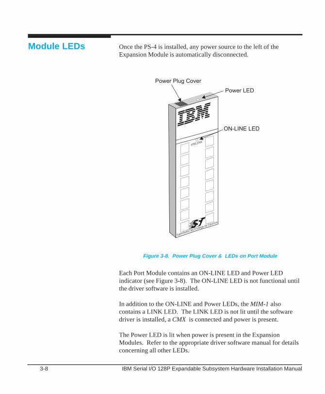
Module LEDs
Each Port Module contains an ON-LINE LED and Power LEDindicator (see Figure 3-8). The ON-LINE LED is not functional untilthe driver software is installed.
In addition to the ON-LINE and Power LEDs, the MIM-1 alsocontains a LINK LED. The LINK LED is not lit until the softwaredriver is installed, a CMX is connected and power is present.
The Power LED is lit when power is present in the ExpansionModules. Refer to the appropriate driver software manual for detailsconcerning all other LEDs.
Once the PS-4 is installed, any power source to the left of theExpansion Module is automatically disconnected.
Figure 3-8. Power Plug Cover & LEDs on Port Module

Serial I/O Multiplexer Installation 4-1
The IBM Multiplexer Set includes the MIM-1 unit, a CMX16-DB orCMX16-RJ and Power Supply.
CMXs are used when peripheral devices are located more than 200 feet(61m) from the host computer system or when they are located in aseparate building. The CMX is installed near the peripheral devices andis connected to the Adapter via a MIM-1. The MIM-1 is usuallyinstalled near the host computer. A CMX is connected to the MIM-1 viaan unshielded two-twisted pair (UTP) link cable. Both DB-25 and RJ-45 connectors are available in 16-port clusters as shown in Figure 4-1.
4 Serial I/O MultiplexerInstallation
Figure 4-1. MIM-1 to CMX 16-DB or CMX 16-RJ

4-2 IBM Serial I/O 128P Expandable Subsystem Hardware Installation Manual
Wall Mounting
ClusterMultiplexers
CMXs are used to connect the peripheral devices to the ExpansionBus via a link cable and a MIM-1. The CMX is usually located in theimmediate area of the devices to be connected. Figure 4-1 shows thelink cable connection between the MIM-1 and the CMX.
Included with each CMX are two wall mounting brackets and fourscrews. Attach one mounting bracket to the top right side of the unitand attach the other bracket to the bottom left side of the unit. Referto Figure 3-3 for the approximate location of the mounting bracketscrew holes. Note: CMXs are wall mounted the same as portmodules See Chapter 3 for details.
Each Multiplexer Set is supplied with one of the following externalpower adapters:
• Power Adapter PN 37L1482 for 120 VAC power source
• Power Adapter PN 37L1491 for 230 VAC power source
Figure 4-2 shows the location of the Power Adapter Jack.
Power Adapters
Figure 4-2. CMX16-RJ CMX
Serial I/O Multiplexer Installation 4-3
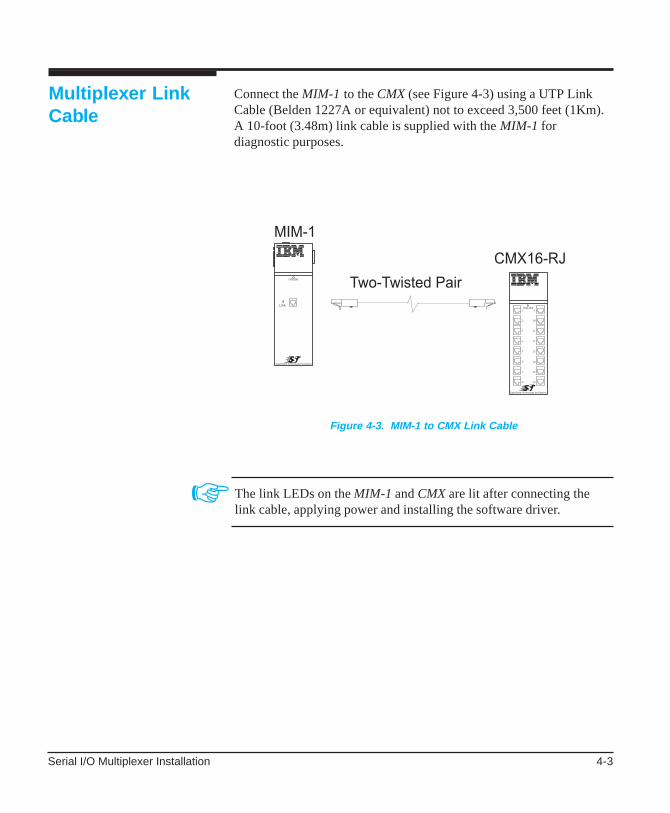
Multiplexer LinkCable
☞
Connect the MIM-1 to the CMX (see Figure 4-3) using a UTP LinkCable (Belden 1227A or equivalent) not to exceed 3,500 feet (1Km).A 10-foot (3.48m) link cable is supplied with the MIM-1 fordiagnostic purposes.
The link LEDs on the MIM-1 and CMX are lit after connecting thelink cable, applying power and installing the software driver.
Figure 4-3. MIM-1 to CMX Link Cable

4-4 IBM Serial I/O 128P Expandable Subsystem Hardware Installation Manual
Figure 4-4 shows a schematic of the two-twisted-pair cable.
Figure 4-4. Multiplexer Link Cable Wiring
Serial I/O Port to Device Cabling 5-1
The Serial I/O Expandable Subsystem supports a wide variety ofdevices (both DCE and DTE), a range of cables from 4-wire RJ-11 to10-wire RJ-45 and several different types of end connectors (DB-25,DB-9, RJ-11 and RJ-45).
All Serial I/O ports provide a standard RS-232 interface with fullmodem control signals.
To assist in wiring the I/O ports, Equinox sells a complete set ofcabling accessories. See www.equinox.com for more information.
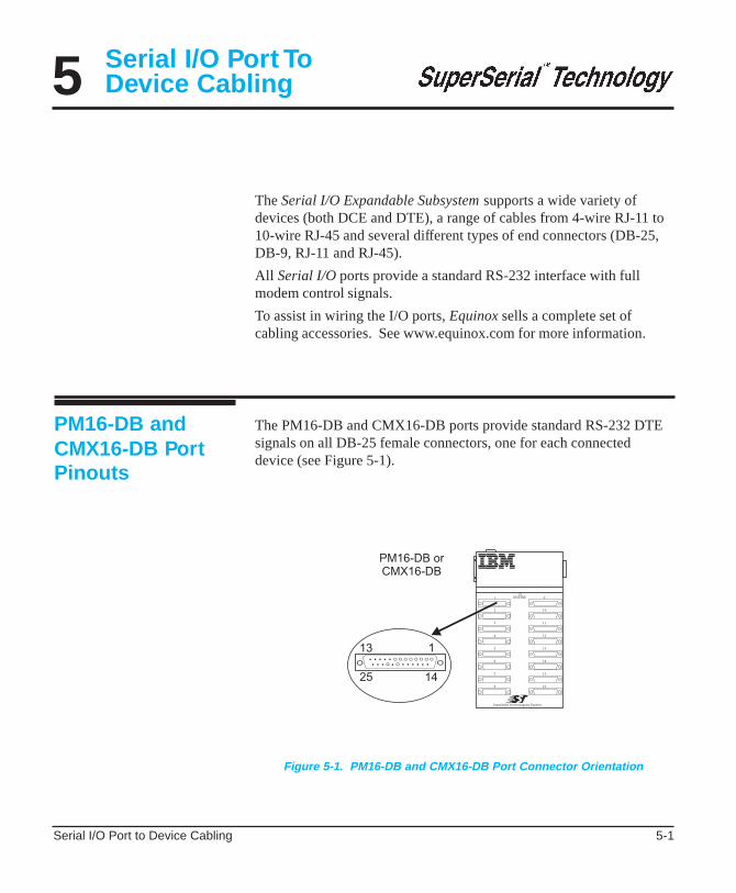
The PM16-DB and CMX16-DB ports provide standard RS-232 DTEsignals on all DB-25 female connectors, one for each connecteddevice (see Figure 5-1).
PM16-DB andCMX16-DB PortPinouts
5 Serial I/O Port ToDevice Cabling
Figure 5-1. PM16-DB and CMX16-DB Port Connector Orientation

5-2 IBM Serial I/O 128P Expandable Subsystem Hardware Installation Manual
Device wiring is dependent on the specific signal requirements of thesystem peripheral devices. Cable connectors plugged into the PM16-DB or CMX16-DB ports must have a male DB-25 connector. Theconnector on the opposite end of each cable should mate to theperipheral device port (terminal, printer, personal computer ormodem).
Depending on the specific signal requirements of the system peripheraldevices, 3-, 4-, or 7-wire connections can be made.
Figures 5-3 through 5-5 show the cable configurations for theseconnections.
Figures 5-6 and 5-7 illustrates a modem cable.
Figure 5-2. Female DB-25 Connector Pinouts
Device Wiring
The pinouts for all female DB-25 connectors are identical (Figure 5-2).

Serial I/O Port to Device Cabling 5-3
Figure 5-4. Cable for a Terminal or Printer Using DTR Flow Control
For terminals and printers using pin 20 hardware flow control.
For terminals and printers using XON/XOFF flow control.
Four WireConnection
Three WireConnection
Figure 5-3. Pinouts for a Terminal or Printer Cable
5-4 IBM Serial I/O 128P Expandable Subsystem Hardware Installation Manual
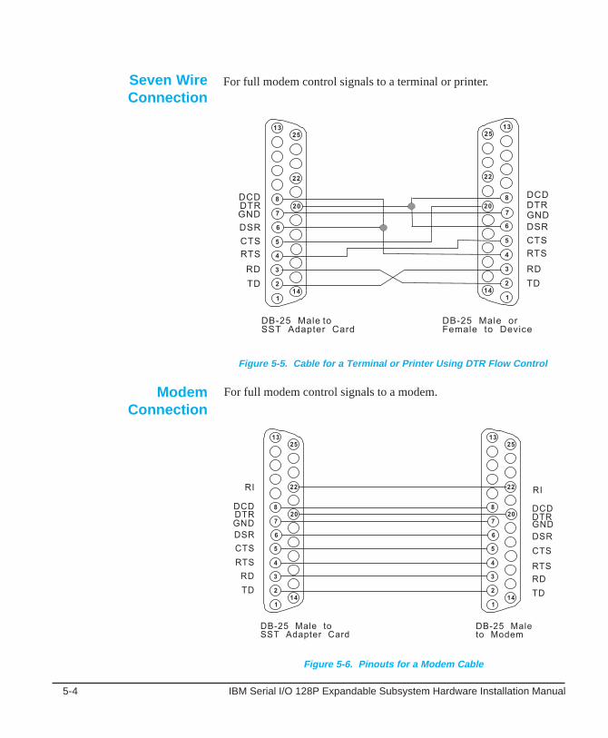
Seven WireConnection
Figure 5-6. Pinouts for a Modem Cable
Figure 5-5. Cable for a Terminal or Printer Using DTR Flow Control
For full modem control signals to a modem.
For full modem control signals to a terminal or printer.
ModemConnection

Serial I/O Port to Device Cabling 5-5
Figure 5-7. Cable to a Personal Computer Serial Port
Personal ComputerSerial Port
For personal computer serial port using DB-9 connector.
5-6 IBM Serial I/O 128P Expandable Subsystem Hardware Installation Manual
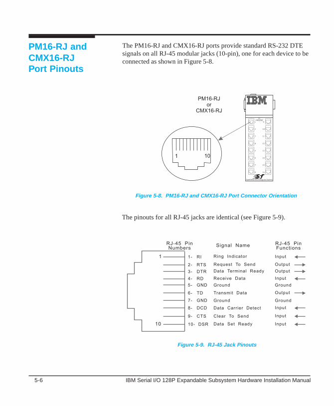
PM16-RJ andCMX16-RJPort Pinouts
Figure 5-8. PM16-RJ and CMX16-RJ Port Connector Orientation
The PM16-RJ and CMX16-RJ ports provide standard RS-232 DTEsignals on all RJ-45 modular jacks (10-pin), one for each device to beconnected as shown in Figure 5-8.
The pinouts for all RJ-45 jacks are identical (see Figure 5-9).
Figure 5-9. RJ-45 Jack Pinouts
Serial I/O Port to Device Cabling 5-7
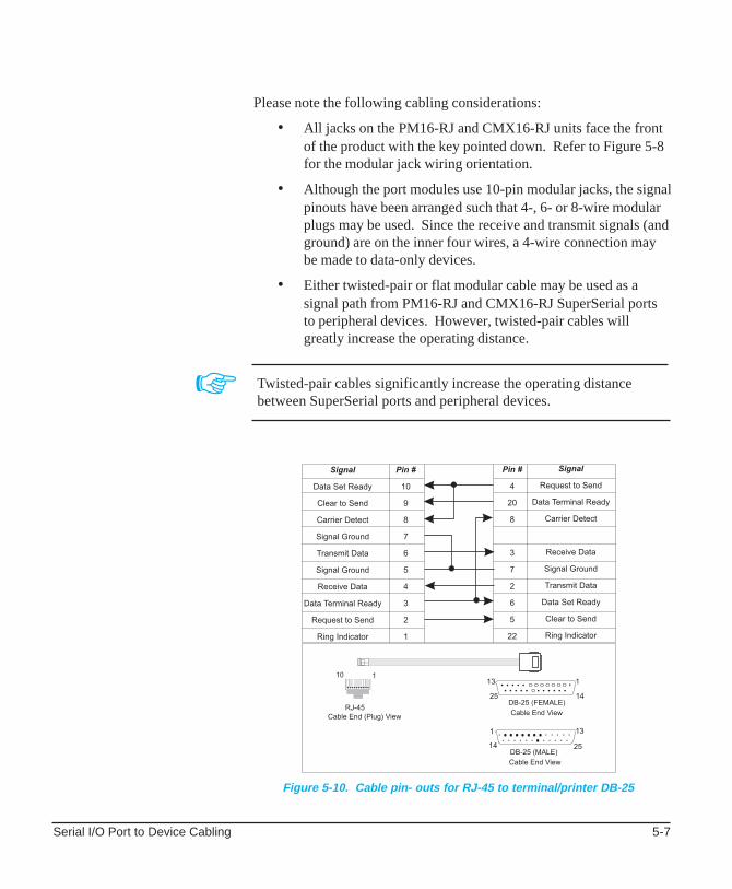
☞
Figure 5-10. Cable pin- outs for RJ-45 to terminal/printer DB-25
Twisted-pair cables significantly increase the operating distancebetween SuperSerial ports and peripheral devices.
Please note the following cabling considerations:
• All jacks on the PM16-RJ and CMX16-RJ units face the frontof the product with the key pointed down. Refer to Figure 5-8for the modular jack wiring orientation.
• Although the port modules use 10-pin modular jacks, the signalpinouts have been arranged such that 4-, 6- or 8-wire modularplugs may be used. Since the receive and transmit signals (andground) are on the inner four wires, a 4-wire connection maybe made to data-only devices.
• Either twisted-pair or flat modular cable may be used as asignal path from PM16-RJ and CMX16-RJ SuperSerial portsto peripheral devices. However, twisted-pair cables willgreatly increase the operating distance.
5-8 IBM Serial I/O 128P Expandable Subsystem Hardware Installation Manual
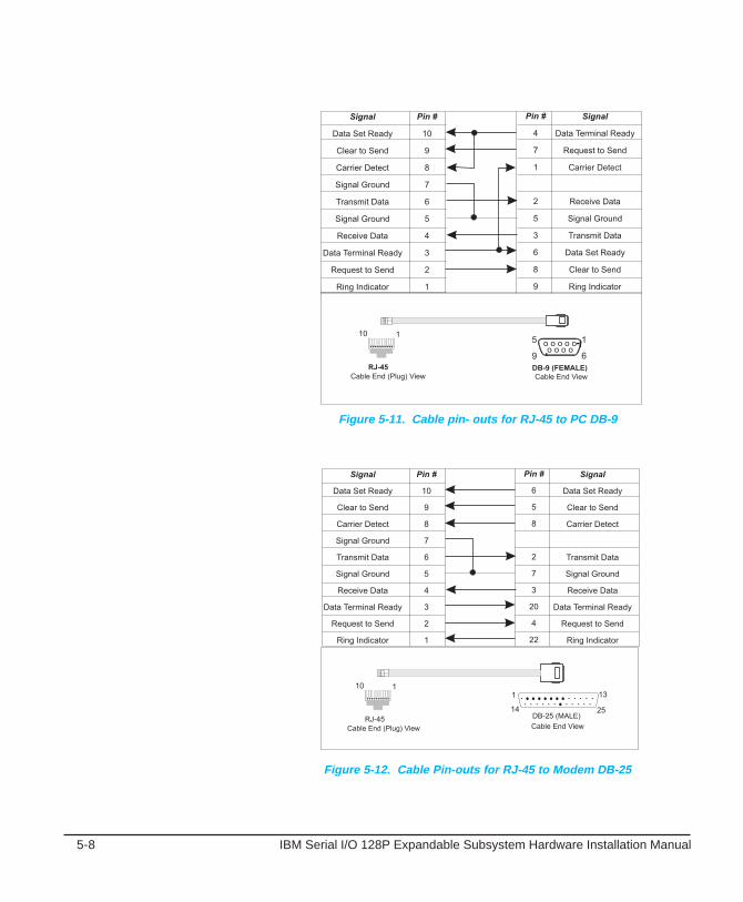
Figure 5-12. Cable Pin-outs for RJ-45 to Modem DB-25
Figure 5-11. Cable pin- outs for RJ-45 to PC DB-9

Serial I/O Port to Device Cabling 5-9
Following are cable diagrams detailing how to build your own cablesto go between a RJ port module and your terminals, printers, PCs,modems, etc.
RJ-45 modular cable is the flat cable used for wiring telephones insideof buildings. The cable is terminated at each end with a RJ-45modular plug (connector) which is inserted into the modular jack of anappropriate wiring module. Standard modular cables available fromEquinox (see www.equinox.com) are reversing. That is, the pins arereversed on each end so that pin 1 on one end is connected to pin 8 or10 on the opposite end, etc. Figure 5-13 illustrates the signals passedthrough modular cables when connected to a PM16-RJ or CMX16-RJSerial I/O port.
☞
Modular Cables
Figure 5-13. RJ-45 Modular Cable Signals
If your operating system does not require RI or DSR, an 8-wire cablemay be used.
5-10 IBM Serial I/O 128P Expandable Subsystem Hardware Installation Manual
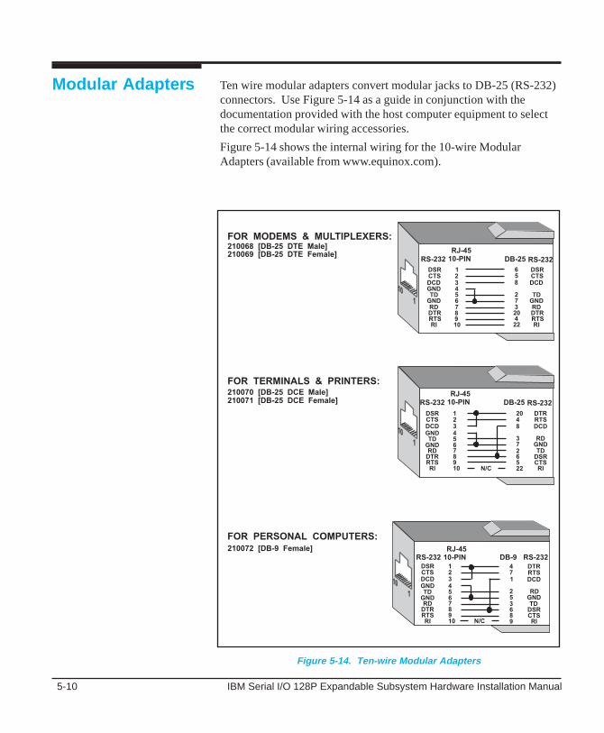
Figure 5-14. Ten-wire Modular Adapters
Modular Adapters Ten wire modular adapters convert modular jacks to DB-25 (RS-232)connectors. Use Figure 5-14 as a guide in conjunction with thedocumentation provided with the host computer equipment to selectthe correct modular wiring accessories.
Figure 5-14 shows the internal wiring for the 10-wire ModularAdapters (available from www.equinox.com).

Power Defaults & Options A-1
A
☞
Power Defaults& Options
IBM Serial I/O Expandable Adapters ship from the factory with thepower straps configured to provide power to the Port Modules via theHost Bus Cable(s). Normally there is no need to reconfigure any ofthe power straps.
If a PS-4 power supply is used, no power is drawn from the hostsystem for the port modules.
This appendix describes the following power defaults and optionalconfigurations for PCI Adapters:
• The default (factory configured) power straps are set to obtainpower for Port Modules 1-4 (ports 1-64) from the hostcomputer backplane(i.e. the PCI Bus) and to obtain power forPort Modules 5-8 (Ports 65-128) from the computer powersupply via J1.
• The power strap connections can be configured to optionallyobtain power for Port Modules 1-8 (Ports 1-128) from thehost computer backplane (i.e. the PCI bus).
A-2 IBM Serial I/O 128P Expandable Subsystem Hardware Installation Manual
Optional PowerConfiguration
Default PowerConfiguration
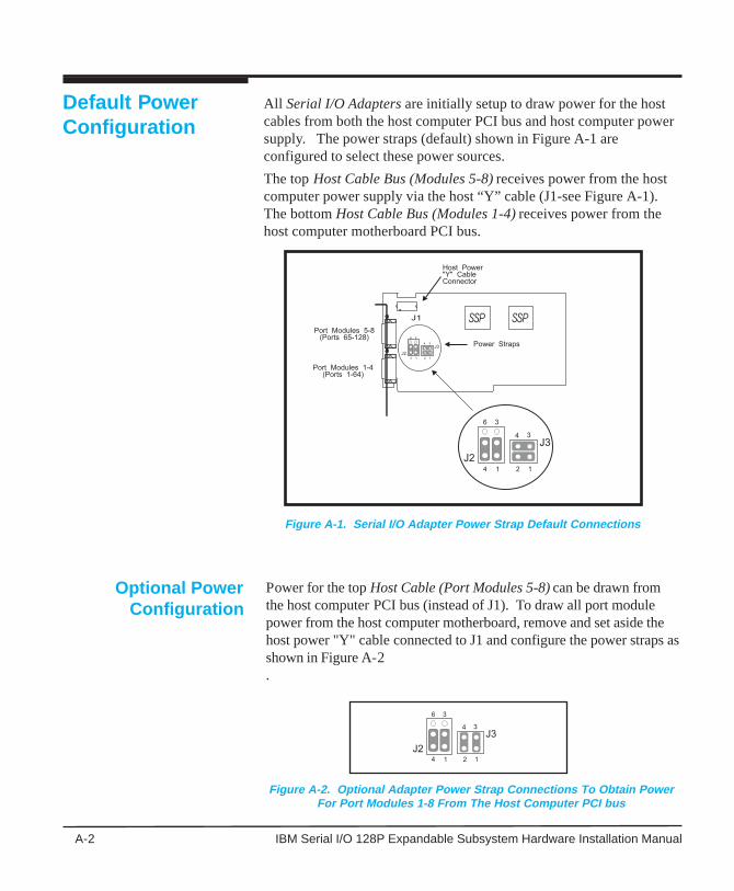
All Serial I/O Adapters are initially setup to draw power for the hostcables from both the host computer PCI bus and host computer powersupply. The power straps (default) shown in Figure A-1 areconfigured to select these power sources.
The top Host Cable Bus (Modules 5-8) receives power from the hostcomputer power supply via the host “Y” cable (J1-see Figure A-1).The bottom Host Cable Bus (Modules 1-4) receives power from thehost computer motherboard PCI bus.
Power for the top Host Cable (Port Modules 5-8) can be drawn fromthe host computer PCI bus (instead of J1). To draw all port modulepower from the host computer motherboard, remove and set aside thehost power "Y" cable connected to J1 and configure the power straps asshown in Figure A-2.
Figure A-1. Serial I/O Adapter Power Strap Default Connections
Figure A-2. Optional Adapter Power Strap Connections To Obtain PowerFor Port Modules 1-8 From The Host Computer PCI bus
Help and Service Information B-1
Help and ServiceInformationB
Before calling for Technical Support, please prepare for your call byfollowing these steps:
To assist the technical support representative, have available as much ofthe following information as possible:
• Computer manufacturer and computer model.
• Options Part Name and Number (from the table below).
• Serial number (if available).
• Proof of purchase (including date and place).
• Exact wording of the error message (if any)
• Description of the problem
• Hardware and software configuration information for your system
If possible, be at your computer. Your technical support representativemight want to walk you through the problem during the call.
Preparing To CallTechnical Support
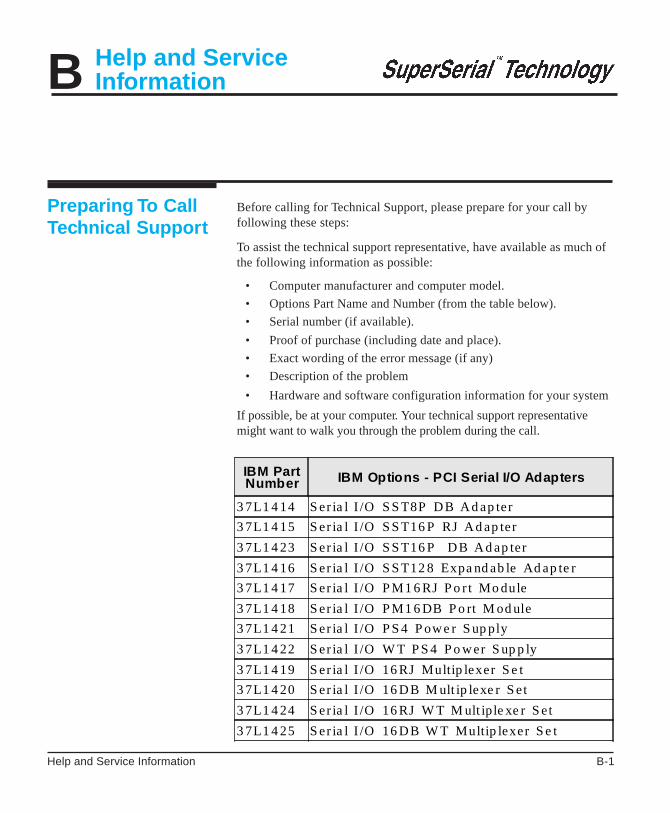
IBM PartNumber IBM Options - PCI Serial I/O Adapters
3 7L1 4 14 S er ia l I /O S S T8P DB Ad ap ter
3 7L1 4 15 S er ia l I /O S S T16 P RJ Ad ap ter
3 7L1 4 23 S er ia l I /O S S T16 P DB Ad ap ter
3 7L1 4 16 S er ia l I /O S S T12 8 Expa nd ab le Ad ap te r
3 7L1 4 17 S er ia l I /O P M1 6 RJ P o r t Mo dule
3 7L1 4 18 S er ia l I /O P M1 6 DB P o rt M od ule
3 7L1 4 21 S er ia l I /O P S 4 P owe r S up ply
3 7L1 4 22 S er ia l I /O W T P S 4 P o wer S up p ly
3 7L1 4 19 S er ia l I /O 16 RJ Multip lexer S e t
3 7L1 4 20 S er ia l I /O 16 DB M ult ip lexe r S et
3 7L1 4 24 S er ia l I /O 16 RJ W T M ult ip le xe r S et
3 7L1 4 25 S er ia l I /O 16 DB W T Multip lexer S e t

B-2 IBM Serial I/O 128P Expandable Subsystem Hardware Installation Manual
Technical support is available during the warranty period to answer anyquestions about your new IBM OPTION. Support response time will varydepending on the number and nature of calls received.
Marketing, installation, and configuration support will be withdrawnfrom the PC Company HelpCenter 90 days after the option has beenwithdrawn from marketing.
If you call 90 days after the date of withdrawal or after your warranty hasexpired, you might be charged a fee. Additional support is availablethrough the IBM PC Company automated Fax system, the PC CompanyWeb Page, the PC Company Electronic Bulletin Board System andHelpWare offerings.
• The IBM web site at “http://www.pc.ibm.com
• The IBM Fax system at (800) 426-3395 or (919) 517-0011
• The IBM BBS system at (919) 517-0001
For the support telephone and support hours by country, refer to thefollowing table or to an optional enclosed technical support insert. If thenumber is not provided in the table or insert, contact your IBM reseller orIBM marketing representative.
Placing the Call toIBM
Support 24 hours a day, 7 days a week
Canada 1-800-426-7378
United States/ Puerto Rico 1-800-426-7378

Help and Service Information B-3
The following warranty information applies to products purchased in theUnited States, Canada, and Puerto Rico. For warranty terms andconditions for products purchased in other countries, see the enclosedWarranty insert, or contact your IBM reseller or IBM marketingrepresentative. International Business Machines Corporation Armonk,New York, 10504
The warranties provided by IBM in this Statement of Limited Warrantyapply only to Machines you originally purchase for your use, and not forresale, from IBM or your reseller. The term “Machine” means an IBMmachine, its features, conversions, upgrades, elements, or accessories, orany combination of them.
Unless IBM specifies otherwise, the following warranties apply only inthe country where you acquire the Machine. If you have any questions,contact IBM or your reseller.
Each Machine is manufactured from new parts, or new and used parts. Insome cases, the Machine may not be new and may have been previouslyinstalled. Regardless of the Machine’s production status, IBM’s warrantyterms apply.
IBM warrants that each Machine
1) is free from defects in materials and workmanship and
2) conforms to IBM’s Official Published Specifications.
The warranty period for a Machine is a specified, fixed periodcommencing on its Date of Installation. The date on your receipt is theDate of Installation, unless IBM or your reseller informs you otherwise.During the warranty period IBM or your reseller, if authorized by IBM,will provide warranty service under the type of service designated for theMachine and will manage and install engineering changes that apply tothe Machine.
For IBM or your reseller to provide warranty service for a feature,conversion, or upgrade, IBM or your reseller may require that the
Product Warranty
Statement of LimitedWarranty
Production Status
The IBM Warranty forMachines

B-4 IBM Serial I/O 128P Expandable Subsystem Hardware Installation Manual
Machine on which it is installed be:
1) for certain Machines, the designated, serial-numbered Machineand
2) at an engineering-change level compatible with the feature,conversion, or upgrade.
Many of these transactions involve the removal of parts and their returnto IBM.
You represent that all removed parts are genuine and unaltered. A partthat replaces a removed part will assume the warranty service status ofthe replaced part.
If a Machine does not function as warranted during the warranty period,IBM or your reseller will repair it or replace it with one that is at leastfunctionally equivalent, without charge. The replacement may not benew, but will be in good working order. If IBM or your reseller is unableto repair or replace the Machine, you may return it to your place ofpurchase and your money will be refunded.
If you transfer a Machine to another user, warranty service is available tothat user for the remainder of the warranty period. You should give yourproof of purchase and this Statement to that user. However, for Machineswhich have a life-time warranty, this warranty is not transferable.
To obtain warranty service for the Machine, you should contact yourreseller or call IBM.
IBM or your reseller will provide certain types of repair and exchangeservice, either at your location or at IBM’s or your reseller’s servicecenter, to restore a Machine to good working order.
When a type of service involves the exchange of a Machine or part, theitem IBM or your reseller replaces becomes its property and thereplacement becomes yours.
You represent that all removed items are genuine and unaltered. Thereplacement may not be new, but will be in good working order and atleast functionally equivalent to the item replaced. The replacement
Warranty Service
In the United States call IBM at 1-800-426-7378In Canada, call IBM at 1-800-426-7378
You may be required to present proof of purchase

Help and Service Information B-5
assumes the warranty service status of the replaced item. Before IBM oryour reseller exchanges a Machine or part, you agree to remove allfeatures, parts, options, alterations, and attachments not under warrantyservice. You also agree to ensure that the Machine is free of any legalobligations or restrictions that prevent its exchange.
You agree to:
1. obtain authorization from the owner to have IBM or yourreseller service a Machine that you do not own; and
2. where applicable, before service is provided —
a) follow the problem determination, problem analysis, andservice request procedures that IBM or your resellerprovide,
b) secure all programs, data, and funds contained in aMachine, and
c) inform IBM or your reseller of changes in a Machine’slocation.
IBM is responsible for loss of, or damage to, your Machine while it is
1) in IBM’s possession or
2) in transit in those cases where IBM is responsible for thetransportation charges.
IBM does not warrant uninterrupted or error-free operation of a Machine.
The warranties may be voided by misuse, accident, modification,unsuitable physical or operating environment, improper maintenance byyou, removal or alteration of Machine or parts identification labels, orfailure caused by a product for which IBM is not responsible.
THESE WARRANTIES REPLACE ALL OTHER WARRANTIES ORCONDITIONS, EXPRESS OR IMPLIED, INCLUDING, BUT NOTLIMITED TO, THE IMPLIED WARRANTIES OR CONDITIONS OFMERCHANTABILITY AND FITNESS FOR A PARTICULAR PURPOSE.THESE WARRANTIES GIVE YOU SPECIFIC LEGAL RIGHTS ANDYOU MAY ALSO HAVE OTHER RIGHTS WHICH VARY FROMJURISDICTION TO JURISDICTION. SOME JURISDICTIONS DO NOTALLOW THE EXCLUSION OR LIMITATION OF EXPRESS ORIMPLIED WARRANTIES, SO THE ABOVE EXCLUSION ORLIMITATION MAY NOT APPLY TO YOU. IN THAT EVENT SUCHWARRANTIES ARE LIMITED IN DURATION TO THE WARRANTY
Extent of Warranty

B-6 IBM Serial I/O 128P Expandable Subsystem Hardware Installation Manual
PERIOD. NO WARRANTIES APPLY AFTER THAT PERIOD.
Circumstances may arise where, because of a default on IBM’s part orother liability you are entitled to recover damages from IBM. In eachsuch instance, regardless of the basis on which you are entitled to claimdamages from IBM (including fundamental breach, negligence,misrepresentation, or other contract or tort claim), IBM is liable only for:
1. damages for bodily injury (including death) and damage to realproperty and tangible personal property; and
2. the amount of any other actual direct damages or loss, up to thegreater of U.S. $100,000 or the charges (if recurring, 12 months’charges apply) for the Machine that is the subject of the claim.
UNDER NO CIRCUMSTANCES IS IBM LIABLE FOR ANY OF THEFOLLOWING:
1) THIRD-PARTY CLAIMS AGAINST YOU FOR LOSSES ORDAMAGES (OTHER THAN THOSE UNDER THE FIRST ITEMLISTED ABOVE);
2) LOSS OF, OR DAMAGE TO, YOUR RECORDS OR DATA;
3) SPECIAL, INCIDENTAL, OR INDIRECT DAMAGES OR FORANY ECONOMIC CONSEQUENTIAL DAMAGES(INCLUDING LOST PROFITS OR SAVINGS), EVEN IF IBMOR YOUR RESELLER IS INFORMED OF THEIRPOSSIBILITY. SOME JURISDICTIONS DO NOT ALLOW THEEXCLUSION OR LIMITATION OF INCIDENTAL ORCONSEQUENTIAL DAMAGES, SO THE ABOVE EXCLUSIONOR LIMITATION MAY NOT APPLY TO YOU.
Limitation ofLiability
The following terms used in this publication, are Trademarks of the IBMCorporation in the United States or other countries:
IBM HelpCenter
Windows NT, Windows95 and Windows98 are Trademarks or RegisteredTrademarks of Microsoft Corporation.
Equinox is a Registered Trademark of Equinox Systems, Inc.
Other company, product, and service names, which may be denoted by adouble asterisk (**), may be trademarks or service marks of others.
Trademarks

Help and Service Information B-7
ElectronicEmission Notices
Federal Communications Commission (FCC) Statement
Note: This equipment has been tested and found to comply with thelimits for a Class A digital device, pursuant to Part 15 of the FCC Rules.These limits are designed to provide reasonable protection againstharmful interference when the equipment is operated in a commercialenvironment. This equipment generates, uses, and can radiate radiofrequency energy and, if not installed and used in accordance with theinstruction manual, may cause harmful interference to radiocommunications. Operation of this equipment in a residential area islikely to cause harmful interference, in which case the user will berequired to correct the interference at his own expense.
Properly shielded and grounded cables and connectors must be used inorder to meet FCC emission limits. IBM is not responsible for any radioor television interference caused by using other than recommended cablesand connectors or by unauthorized changes or modifications to thisequipment. Unauthorized changes or modifications could void the user’sauthority to operate the equipment.
This device complies with Part 15 of the FCC Rules. Operation issubject to the following two conditions: (1) this device may not causeharmful interference, and (2) this device must accept any interferencereceived, including interference that may cause undesired operation.
Industry Canada Class A Emission Compliance Statement
This Class A digital apparatus complies with Canadian ICES-003.
Avis de conformitJ B la rJglementation d’Industrie Canada
Cet appareil numJrique de la classe A est conform B la normeNMB-003 du Canada.

B-8 IBM Serial I/O 128P Expandable Subsystem Hardware Installation Manual

Help and Service Information B-9

B-10 IBM Serial I/O 128P Expandable Subsystem Hardware Installation Manual
© 1998 IBM. All rights reserved. Reproduction without permissionprohibited.
IBM makes no representations or warranties with respect to the contentshereof and specifically disclaims any implied warranties of merchantabilityor fitness for any particular purpose. Information is subject to changewithout notice and does not represent a commitment on the part of IBM.
IBM Serial I/O Expandable Subsystem Hardware Installation Manual Index-1
Index
Symbols
128-port Adapter. ............................................... 2-216-port Cluster Multiplexer ............................... 1-4
A
Adapter, ......................................... 1-7, 1-11, 2-1Installation ..................................................... 2-1
B
Bar Code Readers .............................................. 1-3Belden 1227A .................................................... 4-3Black-anodized Mounting Screws ..................... 3-2Brackets
Coupler .......................................................... 3-2
C
Cable .................... 1-3, 1-4, 1-6, 1-9, 1-10, 1-12host expansion bus ......................................... 1-6host power “Y” .............................................. 2-2jackscrew studs .............................................. 3-5
Cable Pin-outsRJ-45 to Modem ............................................ 5-8RJ-45 to PC.................................................... 5-8RJ-45 to Terminal/Printer .............................. 5-7
Cash Registers ................................................... 1-3Cluster Multiplexer (CMX) .............. 3-1, 4-1, 4-2Cluster Multiplexers (CMX).............................. 1-4CMX .................................................................. 1-5CMX16-DB ....................................................... 5-1Connector Orientation
CMX16-DB ................................................... 5-1CMX16-RJ .................................................... 5-6PM16-DB ...................................................... 5-1PM16-RJ ........................................................ 5-6
Coupler Brackets ............................................... 3-2
D
DCE ................................................................... 5-1Device Wiring .................................................... 5-2DOS ................................................................... 1-2DTE ................................................................... 5-1
E
EBC ................................................................... 3-5EBCs .................................................................. 1-7Expansion Bus1-3, 1-4, 1-6, 1-8, 1-9, 1-10, 1-12
Cable ..................................................... 1-6, 3-2Installation ................................................. 3-4
Expansion Module 1-1, 1-3, 1-4, 1-6, 1-7, 1-8,.................................................... 1-9, 1-10, 1-12
Installation ............................................3-1, 5-1Power Plug Cover .......................................... 3-7
Expansion Module Installation .......................... 3-1Expansion Modules ........................................... 1-4External Power
Adapter .......................................................... 4-2
F
Flat Modular Cable ............................................ 5-7Four Wire Connection ....................................... 5-3Four-wire Connection ........................................ 5-3Full Modem Control Signals.............................. 5-1
H
Host Cable ........................................ 1-3, 3-2, 3-4Connecting to Controller ............................... 3-4
Host Power “Y” Cable ....................................... 2-2
I
InstallingExpansion Modules ....................................... 3-2

Index-2 IBM Serial I/O Expandable Subsystem Hardware Installation Manual
PS-4 Power Supply ........................................ 3-7
J
Jack-screw StudsInstalling ........................................................ 3-5
L
Link Cable ......................................................... 4-1Belden 1227A ................................................ 4-3
LINK LED ......................................................... 3-8
M
MIM .................................................. 1-5, 4-1, 4-2MIM-1 ............................................................... 3-1Modem Connection ........................................... 5-4Modems ............................................................. 1-3Modular Adapters ............................................ 5-10Modular Cables ................................................. 5-9Modular Jacks
10-pin ............................................................. 5-7Modular Plugs
4-wire ............................................................. 5-76-wire ............................................................. 5-78-wire ............................................................. 5-7
Module LEDs .................................................... 3-8Mounting Single Module ................................... 3-3Multi-building Facility ....................................... 1-4Multiplexer
Installation ..................................................... 4-1Interface Module ........................................... 4-1Link Cable Wiring ......................................... 4-4Types.............................................................. 1-5
Multiplexer Interface Modules .......................... 1-4Multiplexer Interface Modules (MIM), ............. 1-4Multiplexer Link Cable...................................... 4-3Multiplexer Set .................................................. 1-4
N
Nickel-PlatedMounting Screws ........................................... 3-2
Novell ................................................................ 1-2
O
ON-LINE LED .................................................. 3-8Overview............................................................ 1-1
P
PCI ............................................................ 1-2, 2-1Personal Computer Serial Port .......................... 5-5Pin 20 Hardware Flow Control
Terminals ....................................................... 5-3Pin-outs
DB-25 ............................................................ 5-2Full Modem Applications .............................. 5-4Full Modem Control ............................. 5-4, 5-5Printer Using Hardware Flow Control ........... 5-3Terminal ......................................................... 5-3Terminal Using Hardware Flow Control ....... 5-3
Plug and play ..................................................... 2-1PM16-DB .......................................................... 5-1PM16-DB and CMX16-DB Port Pinouts .......... 5-1Port Connector Orientation
CMX16-RJ .................................................... 5-6PM16-RJ ........................................................ 5-6
Port Pin-outs ...................................................... 5-1CMX16-RJ .................................................... 5-6PM16-RJ ............................................... 5-1, 5-6
Port To Device Cabling ..................................... 5-1Power
Adapter ........................................................ 1-10Adapter Jack. ................................................. 4-2External .......................................................... 1-9LED ............................................................... 3-8Options .......................................................... 1-8

IBM Serial I/O Expandable Subsystem Hardware Installation Manual Index-3
Plug Cover ..................................................... 3-7Strap Connections ......................................... A-1
Power Adapter ......................................... 1-10, 4-2Power Defaults & Options ................................ A-1Power Options ................................................... 1-8Power Supply ..................................................... 1-4Printers ............................................................... 1-3PS-4 .......................................................... 1-9, 3-7
Installing Power Supply ................................. 3-7Power Cable................................................... 3-7
PS-4 Power Supply ............................................ 1-9
R
RJ-45 Jack Pin-outs ........................................... 5-6RJ-45 Modular Cable Signals ............................ 5-9RJ-45 Modular Plug .......................................... 5-9RS-232 Interface ................................................ 5-1
S
Serial I/O128-port Host Controller ............................... 1-3Adapter ........................................... 1-1, 1-7, 2-1
Installation & Setup ................................... 2-1CMX .............................................................. 4-2Expanded I/O Subsystem ............................... 5-1Multiplexer Installation ........................ 3-6, 4-1Port Modules ................................................. 3-1
Seven-wire Connection ...................................... 5-4Studs
installing ........................................................ 3-5SuperSerial ................................... 1-11, 1-12, 5-1System Setup
PCI ................................................................. 2-1
T
Ten-wire Modular Adapters............................. 5-10Terminals ........................................................... 1-3Three Wire Connection ...................................... 5-3
Twisted-pair Cable ............................................. 5-7Two-twisted-pair link ......................................... 1-4
U
UNIX ................................................................. 1-2Unshielded Two-twisted Pair ............................. 4-1UTP ................................................................... 4-3UTP Link Cable ................................................. 4-1
W
Wall Mounting ................................................... 4-2
X
XON/XOFF flow control ................................... 5-3
Y
“Y” cable ........................................................... 2-2

Index-4 IBM Serial I/O Expandable Subsystem Hardware Installation Manual