Sequential circuit analysishowardhuang.us/teaching/cs231/12-Sequential-circuit-analysis.pdf · July...
30
July 14, 2003 ©2000-2003 Howard Huang 1 Sequential circuit analysis Last week we started talking about memory. — The outputs of a sequential circuit depend on not only the inputs, but also on what’s stored in the circuit’s memory. — Latches and flip-flops are basic one-bit memory units. Today we’ll finish up our discussion of flip-flops. — There are several variations of our basic flip-flop from last week. — Understanding the timing of flip-flops is important. Then we’ll also see some examples of sequential circuits, and learn how to analyze and describe them.
-
Upload
vuongduong -
Category
Documents
-
view
222 -
download
2
Transcript of Sequential circuit analysishowardhuang.us/teaching/cs231/12-Sequential-circuit-analysis.pdf · July...

July 14, 2003 ©2000-2003 Howard Huang 1
Sequential circuit analysis
Last week we started talking about memory.— The outputs of a sequential circuit depend on not only the inputs, but
also on what’s stored in the circuit’s memory.— Latches and flip-flops are basic one-bit memory units.
Today we’ll finish up our discussion of flip-flops.— There are several variations of our basic flip-flop from last week.— Understanding the timing of flip-flops is important.
Then we’ll also see some examples of sequential circuits, and learn how to analyze and describe them.
July 14, 2003 Sequential circuit analysis 2
A positive edge-triggered D flip-flop
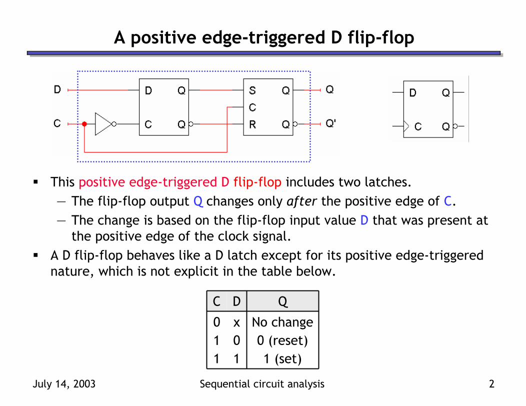
This positive edge-triggered D flip-flop includes two latches.— The flip-flop output Q changes only after the positive edge of C.— The change is based on the flip-flop input value D that was present at
the positive edge of the clock signal.A D flip-flop behaves like a D latch except for its positive edge-triggered nature, which is not explicit in the table below.
1 (set)110 (reset)01
No changex0
QDC

July 14, 2003 Sequential circuit analysis 3
Direct inputs
Most flip-flops also provide direct inputs, or asynchronous inputs, that let you immediately set or clear the state, regardless of the clock input.Such inputs are especially useful for setting the initial state of a flip-flop.Here is a LogicWorks D flip-flop with active-low direct inputs.
1 (set)11110 (reset)0111
No changex011
0 (reset)xx011 (set)xx10Avoidxx00
QDCR’S’
Direct inputs set or reset the flip-flop asynchronously
Set S’R’ = 11 for normal operation of the flip-flop

July 14, 2003 Sequential circuit analysis 4
Flip-flop variations
We can make different versions of flip-flops based on the D flip-flop, just like we made different latches based on the S’R’ latch.The JK flip-flop has inputs that act like S and R, but JK = 11 complementsthe flip-flop’s current state.
A T flip-flop can only maintain or complement its current state.
Q’current1111 (set)011
0 (reset)101No change001No changexx0
QnextKJC
Q’current11No change01No changex0
QnextTC
July 14, 2003 Sequential circuit analysis 5
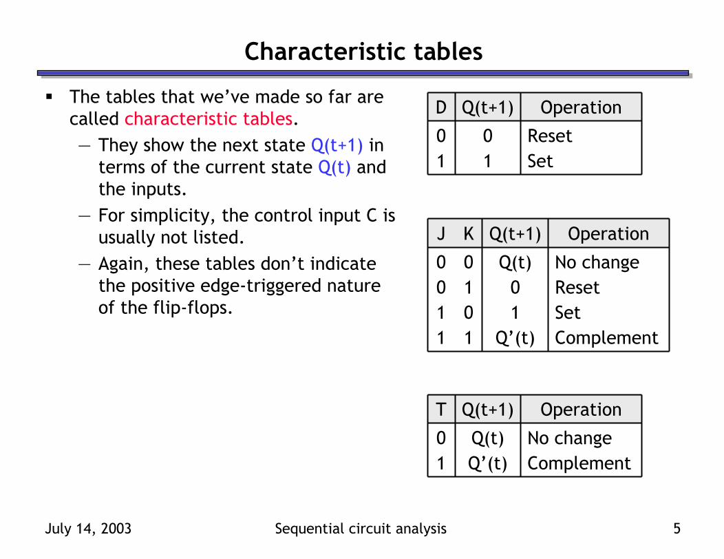
Characteristic tables
The tables that we’ve made so far are called characteristic tables.— They show the next state Q(t+1) in
terms of the current state Q(t) and the inputs.
— For simplicity, the control input C is usually not listed.
— Again, these tables don’t indicate the positive edge-triggered nature of the flip-flops.
Set11Reset00
OperationQ(t+1)D
ComplementQ’(t)11Set101Reset010No changeQ(t)00
OperationQ(t+1)KJ
ComplementQ’(t)1No changeQ(t)0
OperationQ(t+1)T
July 14, 2003 Sequential circuit analysis 6
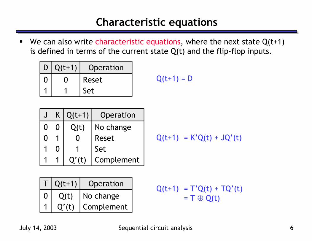
Characteristic equations
We can also write characteristic equations, where the next state Q(t+1) is defined in terms of the current state Q(t) and the flip-flop inputs.
Set11Reset00
OperationQ(t+1)DQ(t+1) = D
ComplementQ’(t)11Set101Reset010No changeQ(t)00
OperationQ(t+1)KJ
Q(t+1) = K’Q(t) + JQ’(t)
ComplementQ’(t)1No changeQ(t)0
OperationQ(t+1)TQ(t+1) = T’Q(t) + TQ’(t)
= T ⊕ Q(t)
July 14, 2003 Sequential circuit analysis 7
Flip-flop timing diagrams
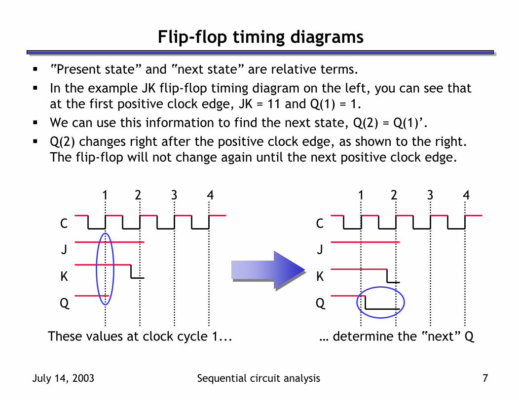
“Present state” and “next state” are relative terms.In the example JK flip-flop timing diagram on the left, you can see that at the first positive clock edge, JK = 11 and Q(1) = 1.We can use this information to find the next state, Q(2) = Q(1)’.Q(2) changes right after the positive clock edge, as shown to the right. The flip-flop will not change again until the next positive clock edge.
C
J
K
Q
1 2 3 4
C
J
K
Q
1 2 3 4
These values at clock cycle 1... … determine the “next” Q
July 14, 2003 Sequential circuit analysis 8
“Present” and “next” are relative
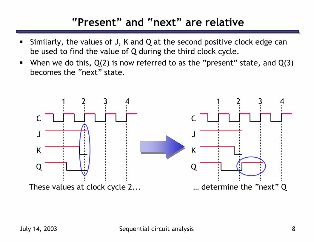
Similarly, the values of J, K and Q at the second positive clock edge can be used to find the value of Q during the third clock cycle.When we do this, Q(2) is now referred to as the “present” state, and Q(3) becomes the “next” state.
C
J
K
Q
1 2 3 4
C
J
K
Q
1 2 3 4
These values at clock cycle 2... … determine the “next” Q

July 14, 2003 Sequential circuit analysis 9
Positive edge triggered
One final point to repeat again one more time: the flip-flop outputs are affected only by the input values at the positive clock edge.— In the diagram below, K changes rapidly between the second and third
positive edges.— But only the inputs at the third positive clock edge (JK = 01 and Q = 1)
will affect the next state. Here, this means Q changes to 0.This is a fairly simple timing model. In real life there are also “setup” and and “hold” times that account for various propagation delays.
C
J
K
Q
1 2 3 4
July 14, 2003 Sequential circuit analysis 10
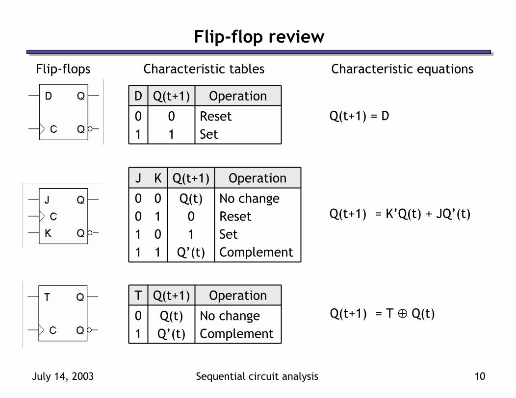
Flip-flop review
Flip-flops Characteristic tables Characteristic equations
Set11Reset00
OperationQ(t+1)D
Q(t+1) = D
ComplementQ’(t)11Set101Reset010No changeQ(t)00
OperationQ(t+1)KJ
Q(t+1) = K’Q(t) + JQ’(t)
ComplementQ’(t)1No changeQ(t)0
OperationQ(t+1)TQ(t+1) = T ⊕ Q(t)
July 14, 2003 Sequential circuit analysis 11
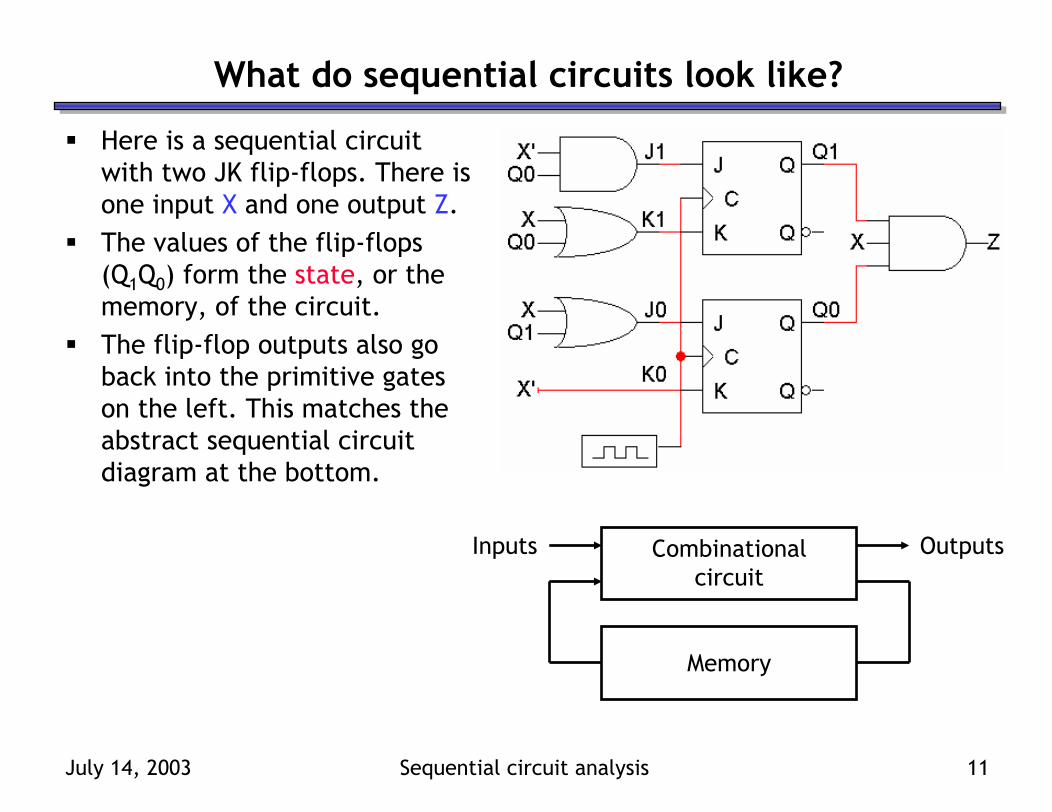
What do sequential circuits look like?
Here is a sequential circuit with two JK flip-flops. There is one input X and one output Z.The values of the flip-flops (Q1Q0) form the state, or the memory, of the circuit.The flip-flop outputs also go back into the primitive gates on the left. This matches the abstract sequential circuit diagram at the bottom.
Combinationalcircuit
Inputs
Memory
Outputs

July 14, 2003 Sequential circuit analysis 12
How do you analyze a sequential circuit?
We can analyze a combinational circuit by deriving a truth table, which shows how the circuit outputs are generated from its inputs.But in a sequential circuit, the outputs are dependent upon not only the inputs, but also the current state of the flip-flops. So to understand how a sequential circuit works, we have to know how the memory changes.A state table is the sequential analog of a truth table. It shows inputs andcurrent states on the left, and outputs and next states on the right.We saw an example of a state table last week, for an SR latch.
010101011001
100110101010
010100101000
Q’QQ’QRSNextCurrentInputs

July 14, 2003 Sequential circuit analysis 13
Analyzing our example circuit
A state table for our example circuit is shown below.The present state Q1Q0 and the input X will determine the next state Q1Q0 and the output Z.
111011101001
110010100000
ZQ0Q1XQ0Q1
OutputsNext StateInputsPresent State

July 14, 2003 Sequential circuit analysis 14
The outputs are easy
From the diagram, you can see that
Z = Q1Q0X
This is an example of a Mealy machine, where the output depends on both the present state (Q1Q0) and the input (X).
1111001101010001
0110001001000000
ZQ0Q1XQ0Q1
OutputsNext StateInputsPresent State

July 14, 2003 Sequential circuit analysis 15
Flip-flop input equations
Finding the next states is harder. To do this, we have to figure out how the flip-flops are changing.
1. Find Boolean expressions for the flip-flop inputs.2. Use these expressions to find the actual flip-flop input values for each
possible combination of present states and inputs.3. Use flip-flop characteristic tables or equations to find the next states,
based on the flip-flop input values and the present states.

July 14, 2003 Sequential circuit analysis 16
Step 1: Flip-flop input equations
For our example, the flip-flop input equations are:
J1 = X’ Q0
K1 = X + Q0
J0 = X + Q1
K0 = X’
JK flip-flops each have twoinputs, J and K. (D and T flip-flops have one input each.)

July 14, 2003 Sequential circuit analysis 17
Step 2: Flip-flop input values
With these equations, we can make a table showing J1, K1, J0 and K0 for the different combinations of present state Q1Q0 and input X.
J1 = X’ Q0 J0 = X + Q1
K1 = X + Q0 K0 = X’
1111
1010
J0
0101
0101
K0
10111110111010100001
10110110101010000000
K1J1XQ0Q1
Flip-flop InputsInputsPresent State

July 14, 2003 Sequential circuit analysis 18
Step 3: Find the next states
Finally, use the JK flip-flop characteristic tables or equations to find the next state of each flip-flop, based on its present state and inputs.The general JK flip-flop characteristic equation was given earlier today.
Q(t+1) = K’Q(t) + JQ’(t)
In our example circuit, we have two JK flip-flops, so we have to apply this equation to each of them.
Q1(t+1) = K1’Q1(t) + J1Q1’(t)Q0(t+1) = K0’Q0(t) + J0Q0’(t)
July 14, 2003 Sequential circuit analysis 19
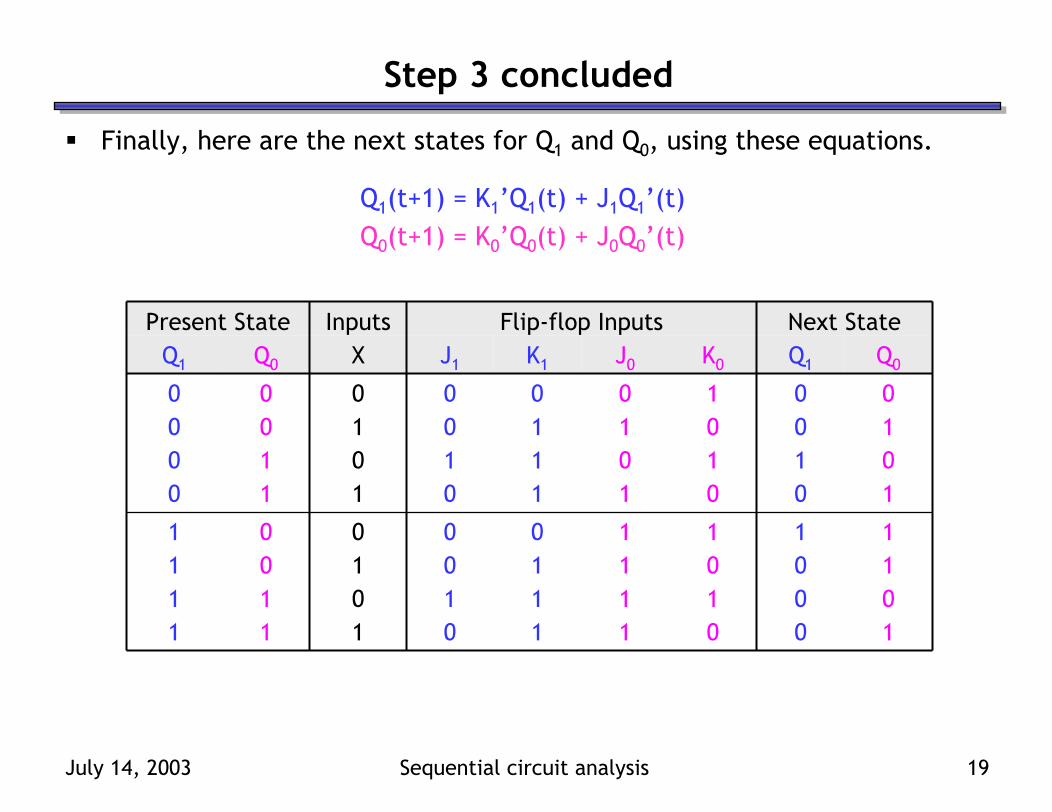
Step 3 concluded
Finally, here are the next states for Q1 and Q0, using these equations.
Q1(t+1) = K1’Q1(t) + J1Q1’(t)Q0(t+1) = K0’Q0(t) + J0Q0’(t)
1011
1010
Q0
0001
0100
Q1
Next State
1111
1010
J0
0101
0101
K0
10111110111010100001
10110110101010000000
K1J1XQ0Q1
Flip-flop InputsInputsPresent State
July 14, 2003 Sequential circuit analysis 20
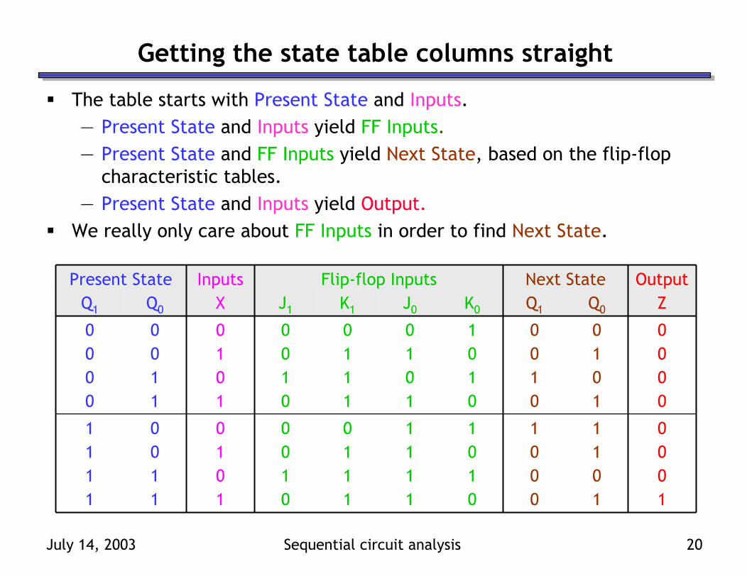
Getting the state table columns straight
The table starts with Present State and Inputs.— Present State and Inputs yield FF Inputs.— Present State and FF Inputs yield Next State, based on the flip-flop
characteristic tables.— Present State and Inputs yield Output.
We really only care about FF Inputs in order to find Next State.
1000
0000
ZOutput
1011
1010
Q0
0001
0100
Q1
Next State
1111
1010
J0
0101
0101
K0
10111110111010100001
10110110101010000000
K1J1XQ0Q1
Flip-flop InputsInputsPresent State

July 14, 2003 Sequential circuit analysis 21
State diagrams
We can also represent the state table graphically with a state diagram.— The diagram has one node for each possible state.— Arrows in the diagram connect present states to next states, and are
labelled with “input/output.”A diagram corresponding to our example state table is shown below.
input output
state
00 01
10
1/0
0/00/0
0/0
0/0 1/0
1/01/1
111000
0000
ZOutput
1011
1010
Q0
0001
0100
Q1
Next State
111011101001
110010100000
XQ0Q1
InputsPresent State
July 14, 2003 Sequential circuit analysis 22
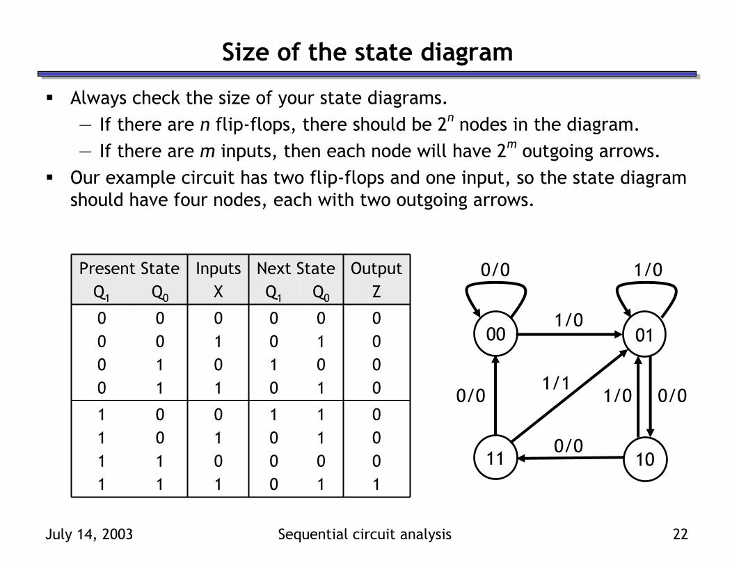
Size of the state diagram
Always check the size of your state diagrams.— If there are n flip-flops, there should be 2n nodes in the diagram.— If there are m inputs, then each node will have 2m outgoing arrows.
Our example circuit has two flip-flops and one input, so the state diagram should have four nodes, each with two outgoing arrows.
1000
0000
ZOutput
1011
1010
Q0
0001
0100
Q1
Next State
111011101001
110010100000
XQ0Q1
InputsPresent State
00 01
1011
1/0
0/00/0
0/0
0/0 1/0
1/01/1

July 14, 2003 Sequential circuit analysis 23
A D flip-flop example
Here are two D flip-flops, with values labelled A and B.There is one input, X.There are no explicit outputs.— In this case, the outputs are
assumed to be the flip-flop values A and B themselves.
— This is an example of a Moore machine, where the outputs depend on only the present state.

July 14, 2003 Sequential circuit analysis 24
Making this in LogicWorks
You’ll need to set the direct inputs R and S. Here we’ve added a Resetswitch; when it is 1, both flip-flops are cleared to 0.The flip-flops have complemented outputs already, so you won’t need to generate A’ and B’ yourself.

July 14, 2003 Sequential circuit analysis 25
Analyzing the example circuit
The basic state table is below.Again, you can see that the present states are being used to generate the next states.For this example, remember that the present state also serves as the output.
BANext State
111011101001
110010100000
XBAInputsPresent State

July 14, 2003 Sequential circuit analysis 26
Step 1: Flip-flop input equations
There are two input equations, one for each flip-flop.
DA = AX’ + A’BX + AB’XDB = B ⊕ X
“DA” indicates a D-type flip-flop, whose output is A.

July 14, 2003 Sequential circuit analysis 27
Step 2: Flip-flop input values
Now that we have the equations for DA and DB, we can fill in actual values for each combination of present state and inputs.
DA = AX’ + A’BX + AB’XDB = B ⊕ X
0110
0110
DB
0111
1000
DA
Flip-flop Inputs
111011101001
110010100000
XBAInputsPresent State
July 14, 2003 Sequential circuit analysis 28
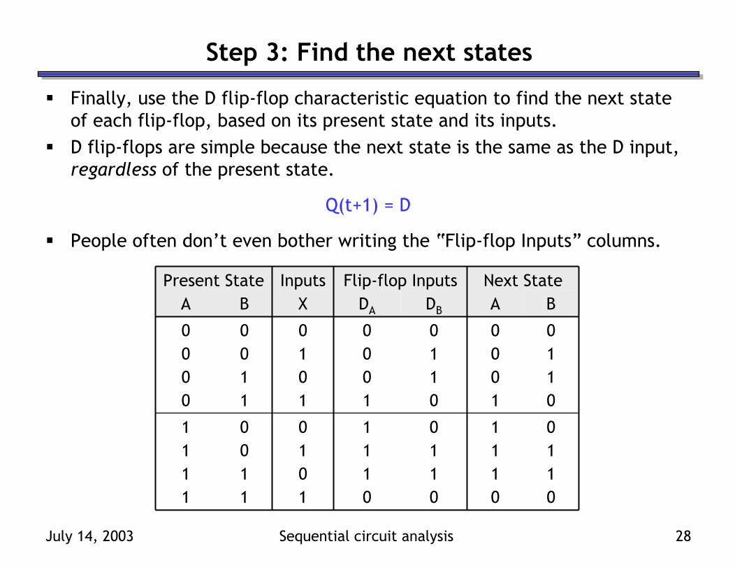
Step 3: Find the next states
Finally, use the D flip-flop characteristic equation to find the next state of each flip-flop, based on its present state and its inputs.D flip-flops are simple because the next state is the same as the D input, regardless of the present state.
Q(t+1) = D
People often don’t even bother writing the “Flip-flop Inputs” columns.
0111
1000
ANext State
0110
0110
B
0110
0110
DB
0111
1000
DA
Flip-flop Inputs
111011101001
110010100000
XBAInputsPresent State

July 14, 2003 Sequential circuit analysis 29
So what does this circuit do?
When X = 0, the next state is the same as the present state.When X = 1, the next state is “one more” than the present state.This is a basic two-bit counter with an enable input, X. It’s also called a modulo-4 counter, since it counts from 0 to 3 repeatedly.
00 01
1011
1
11
1
0 0
000111
1000
ANext State
0110
0110
B
111011101001
110010100000
XBAInputsPresent State
July 14, 2003 Sequential circuit analysis 30
Summary
To analyze sequential circuits, you have to understand how the flip-flops change on each clock cycle, according to their current values and inputs. A state table show all the possible ways that the outputs and state of a sequential circuit can change, based on the its inputs and present state.State diagrams are an alternative way of showing the same information.Next time we’ll look at designing sequential circuits. This is the opposite process—you make a state table and/or diagram first, and then turn that into a sequential circuit.