Sequence Design and Software Environment for Real-Time...
4
Proceedings of the 28th IEEE EMBS Annual International Conference New York City, USA, Aug 30-Sept 3,2006 ThEP4.4 Sequence Design and Software Environment for Real-time Navigation of a Wireless Ferromagnetic Device using MRI System and Single Echo 3D Tracking A. Chanu, Student Member IEEE, E. Aboussouan, S. Tamaz and S. Martel*, Member IEEE NanoRobotics Laboratory, Department of Computer Engineering and Institute of Biomedical Engineering, Ecole Polytechnique de Montrtal (EPM), Campus of the Universitt de Montrtal, Montrtal (Qutbec) Canada "E-mail: [email protected] URL: www.nano.polymtl.ca Abstract-Software architecture for the navigation of a ferromagnetic untethered device in a 1D and 2D phantom environment is briefly described. Navigation is achieved using the real-time capabilities of a Siemens 1.5T Avanto MRI system coupled with a dedicated software environment and a specially developed 3D tracking pulse sequence. Real-time control of the magnetic core is executed through the implementation of a simple PID controller. 1D and 2D experimental results are presented. Keywords-Real-time navigation, microdevice, magnetic resonance, software environment, 3D tracking sequence I. INTRODUCTION Recent advances in real-time MRI interventions allowed a wide range of new potential applications based on this imaging modality. As such, active [ l ] and passive [2] catheter tracking are among the most promising applications. MR-safe catheters and guidewires could soon become a viable alternative to X-ray imaging during vascular interventions. However, catheters are limited in size and flexibility which raises restrictions about the minimum vessel size that can be reached and the additional friction along the vessel's walls created by long sinuous vessels in complex cardiovascular networks. The Magnetic Resonance Submarine (MR-Sub) project [3,4] aims at resolving these constraints with the use of untethered ferromagnetic devices designed for minimally invasive in-vivo interventions. The ferromagnetic core is propelled, tracked and guided through the use of a specially developed real-time MRI sequence. Such device could be used as an extension to current catheters for improved accessibility within the cardiovascular network. Highly targeted drug delivery such as chemotherapy and chemo-embolization are only two applications that are under investigation because of the potential improvement for targeting efficacy to the tumor mass. The software architecture which takes care of the device's navigation is presented as well as the single echo 3D real-time tracking sequence. Experimental results based on 1D and 2D positioning and navigation in a water filled phantom is also discussed. 11. METHODOLOGY A. Experimental Setup 1D and 2D control experiments were performed on a 1.5T Siemens Avanto providing real-time capabilities. A 1010/1020 carbon steel bead with a diameter of 1.5mm was used as the device to be propelled through forces induced in the ferromagnetic material using magnetic gradients generated by the MR-imaging coils. Such propulsion is proportional to the volume of the ferromagnetic core, its magnetization, and applied gradient amplitude [5]. Propulsion in any directions is achieved by generating the required magnetic gradient strength from each of the three orthogonal imaging coils. For simplicity, no flow was considered initially for the experiments described here. To conduct 1D and 2D experiments, the bead is placed in a linear plastic tube and in a square shape glass phantom respectively (Fig.1). Both phantoms are filled with water and placed inside the bore of the MRI system. Fig. 1. Experimental setup used for 1D control loop (left) and 2D control loop (right) 1 -4244-0033-3/06/$20.00 02006 IEEE. 1746
Transcript of Sequence Design and Software Environment for Real-Time...

Proceedings of the 28th IEEE EMBS Annual International Conference New York City, USA, Aug 30-Sept 3,2006
ThEP4.4
Sequence Design and Software Environment for Real-time Navigation of a Wireless Ferromagnetic Device using MRI System
and Single Echo 3D Tracking A. Chanu, Student Member IEEE, E. Aboussouan, S. Tamaz and S. Martel*, Member IEEE
NanoRobotics Laboratory, Department of Computer Engineering and Institute of Biomedical Engineering, Ecole Polytechnique de Montrtal (EPM), Campus of the Universitt de Montrtal, Montrtal (Qutbec) Canada
"E-mail: [email protected] URL: www.nano.polymtl.ca
Abstract-Software architecture for the navigation of a ferromagnetic untethered device in a 1D and 2D phantom environment is briefly described. Navigation is achieved using the real-time capabilities of a Siemens 1.5T Avanto MRI system coupled with a dedicated software environment and a specially developed 3D tracking pulse sequence. Real-time control of the magnetic core is executed through the implementation of a simple PID controller. 1D and 2D experimental results are presented.
Keywords-Real-time navigation, microdevice, magnetic resonance, software environment, 3D tracking sequence
I. INTRODUCTION Recent advances in real-time MRI interventions allowed a
wide range of new potential applications based on this imaging modality. As such, active [ l ] and passive [2] catheter tracking are among the most promising applications. MR-safe catheters and guidewires could soon become a viable alternative to X-ray imaging during vascular interventions. However, catheters are limited in size and flexibility which raises restrictions about the minimum vessel size that can be reached and the additional friction along the vessel's walls created by long sinuous vessels in complex cardiovascular networks. The Magnetic Resonance Submarine (MR-Sub) project [3,4] aims at resolving these constraints with the use of untethered ferromagnetic devices designed for minimally invasive in-vivo interventions. The ferromagnetic core is propelled, tracked and guided through the use of a specially developed real-time MRI sequence. Such device could be used as an extension to current catheters for improved accessibility within the cardiovascular network. Highly targeted drug delivery such as chemotherapy and chemo-embolization are only two applications that are under investigation because of the potential improvement for targeting efficacy to the tumor mass. The software architecture which takes care of the device's navigation is presented as well as the single echo
3D real-time tracking sequence. Experimental results based on 1D and 2D positioning and navigation in a water filled phantom is also discussed.
11. METHODOLOGY
A. Experimental Setup 1D and 2D control experiments were performed on a 1.5T
Siemens Avanto providing real-time capabilities. A 1010/1020 carbon steel bead with a diameter of 1.5mm was used as the device to be propelled through forces induced in the ferromagnetic material using magnetic gradients generated by the MR-imaging coils. Such propulsion is proportional to the volume of the ferromagnetic core, its magnetization, and applied gradient amplitude [5]. Propulsion in any directions is achieved by generating the required magnetic gradient strength from each of the three orthogonal imaging coils. For simplicity, no flow was considered initially for the experiments described here.
To conduct 1D and 2D experiments, the bead is placed in a linear plastic tube and in a square shape glass phantom respectively (Fig.1). Both phantoms are filled with water and placed inside the bore of the MRI system.
Fig. 1. Experimental setup used for 1D control loop (left) and 2D control loop (right)
1 -4244-0033-3/06/$20.00 02006 IEEE. 1746
f ,,-_ ,,"~ _,, ,",! ,-,, -,I ,-, ,"," in. L
Fig. 2. Overview of the system software architecture
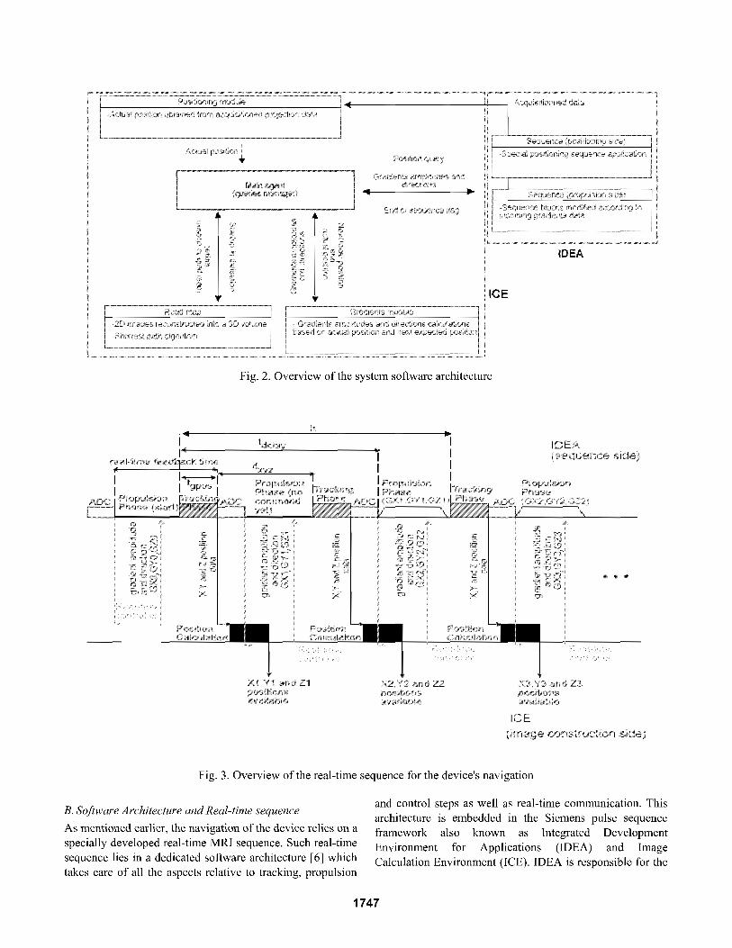
Fig. 3. Overview of the real-time sequence for the device's navigation
and control steps as well as real-time communication. This B. Software Architecture and Real-time sequence architecture is embedded in the Siemens pulse sequence As mentioned earlier, the navigation of the device relies on a framework also known as Integrated Development specially developed real-time MRI sequence. Such real-time Environment for ~ ~ ~ l i ~ ~ ~ i ~ ~ ~ (IDEA) and I~~~~ sequence lies in a dedicated software architecture [6] which Calculation Environment (ICE), IDEA is responsible for the takes care of all the aspects relative to tracking, propulsion
1747

pulse sequence application on the scanner (RF pulses, gradients and ADC for signal reception) as ICE takes care of the image reconstruction from the acquired data. Reference [6] describes in details all the different modules presented in Fig. 2. Emphasis is placed here on the real-time sequence driven by the above mentioned software architecture as well as the 3D tracking sequence for the real-time positioning of the device. The real-time sequence consists of a propulsion phase in which the propulsion (high amplitude) gradients are applied towards a specific orientation in space in the scanner and it is followed by a 3D tracking sequence for the acquisition of the position of the same device. This specially developed 3D tracking sequence using single echo is based on a special technique developed by our group and referred to as the MS-SET tracking method [7]. The method is based upon a non selective RF excitation tuned to the appropriate frequency of protons surrounding the ferromagnetic entity. Since only the specific protons around the object being positioned are selected, projection of the acquired data only reflects the signal coming from such object. The method is then applied for each of the three axes successively. The acquired signal is then sent to the ICE module while the sequence is still running. The signal is projected and correlated with the instant zero position providing the displacement of the device since the last acquired position on each axis. Within the real-time sequence based on the computed positions and the chosen destination, a controller located in another ICE real-time module computes the next gradient amplitude and direction to be applied for the next propulsion phase. An overall illustration of the real-time pulse sequence is illustrated in Fig. 3.
The period of the real-time feedback time as depicted in Fig. 3 and denoted tfeedback is the minimum time allowed for the next gradient calculations from the real-time controller module. This delay must be adjusted according to the complexity of the controller. If this time is not long enough, the real-time loop between the pulse sequence and the ICE modules is interrupted causing a desynchronisation of the real-time process. The 3D tracking sequence uses a single RF excitation before acquiring successively the data on all three axes. Protons refocusing is done through the use of strong dephaser gradients similar to a common gradient echo base sequence. The time for the 3D tracking sequence and denoted tgpos in Fig. 3 is 15 ms. Since both the propulsion phase and the tracking sequence must lie within a minimum time of tfccdback in order for the real-time communication to execute, the duration of the propulsion phase is computed to maximize the time allocated for propulsion and defined as
The destination of the device is determined by a set of waypoints read from a file. Each waypoint is described by three floating point position in space. Once read and loaded
Fig. 4. MRI coordinates referential
in the software architecture, this set acts as a precise path for the device. Each waypoint is read by the controller and considered as the next target position for the next command calculation. When the device is located in a spherical volume with a given precision radius r centered around the waypoint’s coordinates, the software environment loads the next waypoint from the path and sends it to the controller to update the position of the target. This proximity check allows for precise command decision once the device approaches the next waypoint. By following all the given waypoints, the device eventually reaches its final destination in the phantom.
111. RESULTS In order to validate the above mentioned real-time
sequence and software architecture, we implemented a simple 1D [SI and 2D [9] PID controller. The error between the current position of the device and the target coordinates is computed in the real-time ICE module and sent to the controller to determine the next command. The MRI referential as shown in Fig.4 is used for all the experiments.
A. Results for One Dimensional Experiments For 1D control experiments, a single waypoint located at
6 cm away on the x axis acts as the target final position (6,0,0). Simulated and experimental results are shown in Fig. 5. A feedback time (tfeedback) of 30 ms was used,
leading from Eq. 1 to a propulsion time ( tprop ) of 15 ms. To
be able to propel the device during 15 ms, the maximum gradient amplitude was set to 26 mT/m on all three axes in order not to outrange the gradient amplifier limits.
B. Results for Two Dimensional Experiments For the two dimensional control experiment, a single
waypoint located at 6 cm away on the x axis and -6 cm away on the z axis was chosen for the final destination (position (6,0,-6)). Again, simulated and observed data for the position of the device with the time is shown in Fig. 6. The same feedback time of 30 ms is used, leading to a propulsion time of 15 ms.
1748

T fi a ,I,
Fig. 5 . Simulation and experimental data of the device’s position along time for a 6 cm target on the x axis
a
* x - Experimental , z - Experimental
x - Simulation z - Simulation
-4
-6
-a Time (s)
Fig. 6. Simulation and experimental data of the device’s position along time for a 6 cm target on the x axis and a - 6cm target on the z axis
IV. DISCUSSION The one dimensional and two dimensional control
experiments using the available software architecture are both conclusive, leading to a final steady state error of 6.039 mm on the x axis for 1D control and 6.7969 mm on the x axis and 3.75 mm on the z axis for 2D control. Three dimensional propulsion and control is not yet possible using the current gradient coils due to the lack of sufficient force provided by the gradient to levitate the device. However, as depicted in [lo], stronger coils could be integrated in the MRI system, allowing stronger gradients and hence, more force to raise the bead against its own weight. In such a case 3D control tests could be made possible since the system’s architecture and pulse sequence are already taking it into account.
V. CONCLUSION The specially developed 3D tracking sequence using
single echo integrated onto a real-time environment and dedicated software architecture provides the necessary framework to control, propel and track a ferromagnetic
device in a 1D and 2D environment. The next steps in the MR-Sub project involves extensive use of many waypoints for complex navigation as well a 1D and 2D control in a flow environment.
ACKNOWLEDGMENT This project is supported in part by a Canada Research
Chair (CRC) in MicroDJanosystem Development, Fabrication and Validation, the Canada Foundation for Innovation (CFI), the National Sciences and Engineering Research Council of Canada (NSERC), and the Government of Quibec.
REFERENCES
C.M. Hillenbraud, D.R. Elgort, E.Y. Wong, A. Reykowski, F.K. Wacker, J.S. Lewin, J.L. Duerk, “Active device tracking and high- resolution intravascular MRI using a novel catheter-based, opposed- solenoid phased array coil”. Magnetic Resonance Imaging in Medecine. 51: 4. pp. 668-675,2004. R. Van Dcr Wcidc, K.J. Zuidcrvcld, C.J.G Bakkcr, T. Hoogcnboom, J.J. Van Vaals, A. Max. “Image guidancc of cndovascular interventions on a clinical MR scanner”. IEEE Transactions on Medical Imaging. v17, n 5 , Oct, 1998, p 779-785. J.-B. Mathicu, S. Martcl, L.’H. Yahia, G. Soulcz, G. Beaudoin, “MRI systems as a mean of propulsion for a microdevice in blood vessels” Proc. 25lh Annu. Engineering in Medicine and Biology Society, vol. 4, pp. 3419-3422, Sept. 2003. S. Martel, J.-B. Mathieu, 0. Felfoul, H. Macicior, G. Beaudoin, G. Soulez, L.H. Yahia, “Adapting MRI systems to propel and guide microdevices in the human blood circulatoty system” Proc. 26lh Annu. Engineering in Medicine and Biology Society, vol. 1 , pp. 1044-1 047, 2004. J.-B. Mathieu, G. Beaudoin, S. Martel, “Method of propulsion of a ferromagnetic core in the cardiovascular system through magnetic gradients generated by an MRI system” IEEE Trans. Biomedical Engineering vol. 53, no. 2, pp. 292-299, Fcb. 2006. A. Chanu, S. Martel, G. Beaudoin, “Real-time Magnetic Resonance Gradient-based Propulsion of a Wireless Microdevice Using Pre- Acquired Roadmap and Dedicated Software Architecture” (accepted, to bc publishcd), Proc. 271h Annu. Engineering in Medicine and Biology Society, Shangai, Sept 2005. 0. Felfoul, J.-B. Mathieu, G. Beaudoin, S. Martel, “MR-tracking Based on Magnetic Signature Selective Excitation” (in review), IEEE Trans. Medical Imaging. S . Tamaz, S . Martel, “Impact of the MRI-based Navigation System Constraints on the Step Response Using a PID Controller” (accepted, to be published), Proc. 271h Annu. Engineering in Medicine and Biology Society, Shangai, Scpt 2005. S. Tamaz, A. Chanu, J.B. Mathieu, R. Gourdeau, S. Martel “ Rcal- time MRI-based Control of a Ferromagnetic Core for Endovascular Navigation” (in review), IEEE Truns. Biomedical Engineering.
[lo] B. Chronik, A. Alcjski, B.K. Rutt. 2000. “Dcsign and fabrication of a three-axis multilayer gradient coil for magnetic resonance microscopy of mice” Magnetic Resonance Materials in Physics, Biology and Medicine vol. 10, no. 2, pp. 13 1-146, June 2000.
1749