September 25, 2007 Reclassification of Control Rod Drive ...
30
1 September 25, 2007 Reclassification of Control Rod Drive Mechanism (CEDM) 56 NDE Indication Southern California Edison (SCE) San Onofre Nuclear Generating Station (SONGS) Unit 3
Transcript of September 25, 2007 Reclassification of Control Rod Drive ...

1
September 25, 2007
Reclassification of Control Rod Drive Mechanism (CEDM) 56 NDE Indication
Southern California Edison (SCE)San Onofre Nuclear Generating Station
(SONGS) Unit 3

2
Purpose• Based on all information available to
date, SCE has reclassified the indication in CEDM 56 as No Detectable Defect (NDD)– Discuss the technical basis for the
reclassification
– Discuss the licensing issues associated with the reclassification
3
Non Destructive Examination Results for
San Onofre Unit-3 Control Element Drive
Penetration 56
Southern California Edison

4
Key Points
• Determination– The indication in CEDM 56 is not a defect
– Code Relief for Flaw Evaluation is not required
• Basis– Repair of CEDM 56 was based on refuted data
– All supplemental exams were negative for PWSCC
– Indication in CEDM 56 lacks PWSCC features
– Indication is consistent with grain noise
– Current evaluation methodology would conclude no defect is present in CEDM 56

5
Technical Presentation Overview
– Background
– Evaluation
– Conclusion
– Future plans regarding inspections and head replacement
– Discussion
6
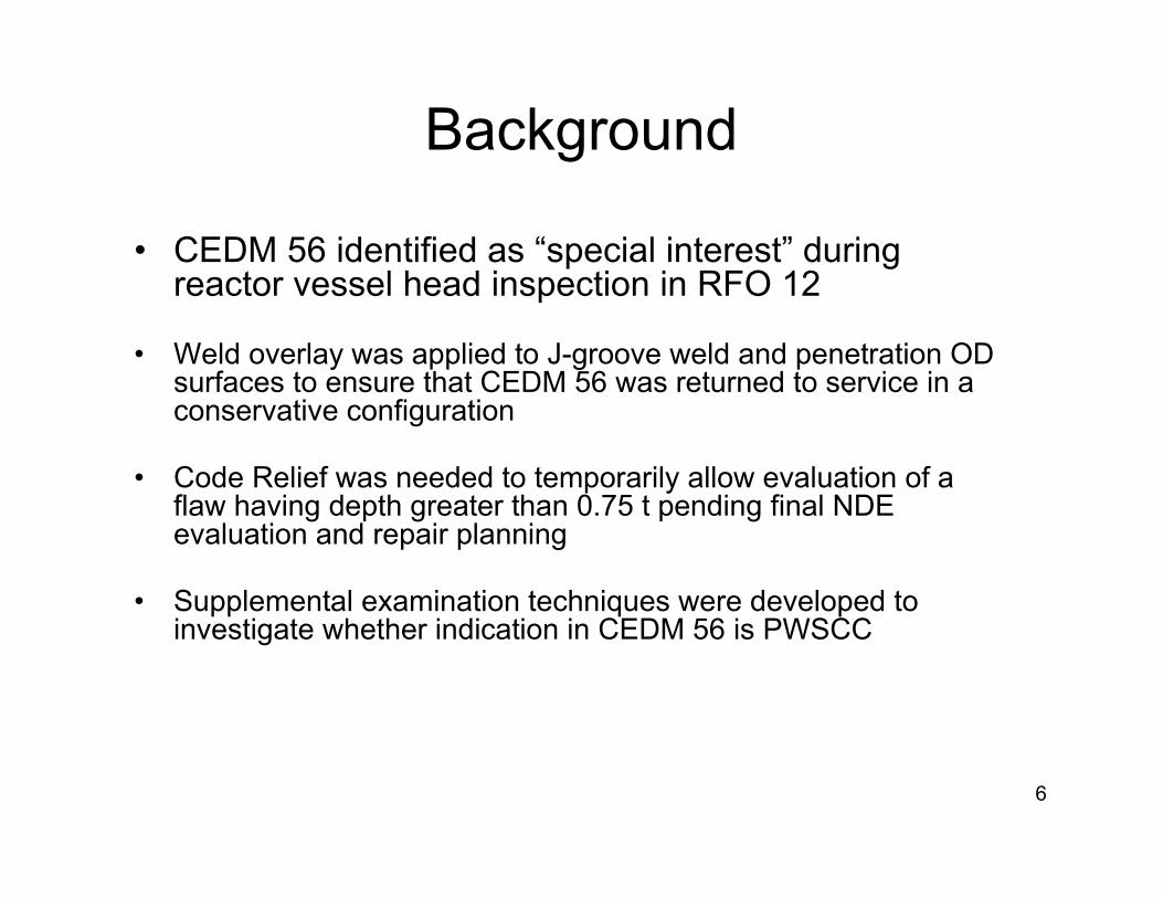
• CEDM 56 identified as “special interest” during reactor vessel head inspection in RFO 12
• Weld overlay was applied to J-groove weld and penetration OD surfaces to ensure that CEDM 56 was returned to service in a conservative configuration
• Code Relief was needed to temporarily allow evaluation of a flaw having depth greater than 0.75 t pending final NDE evaluation and repair planning
• Supplemental examination techniques were developed to investigate whether indication in CEDM 56 is PWSCC
Background
7
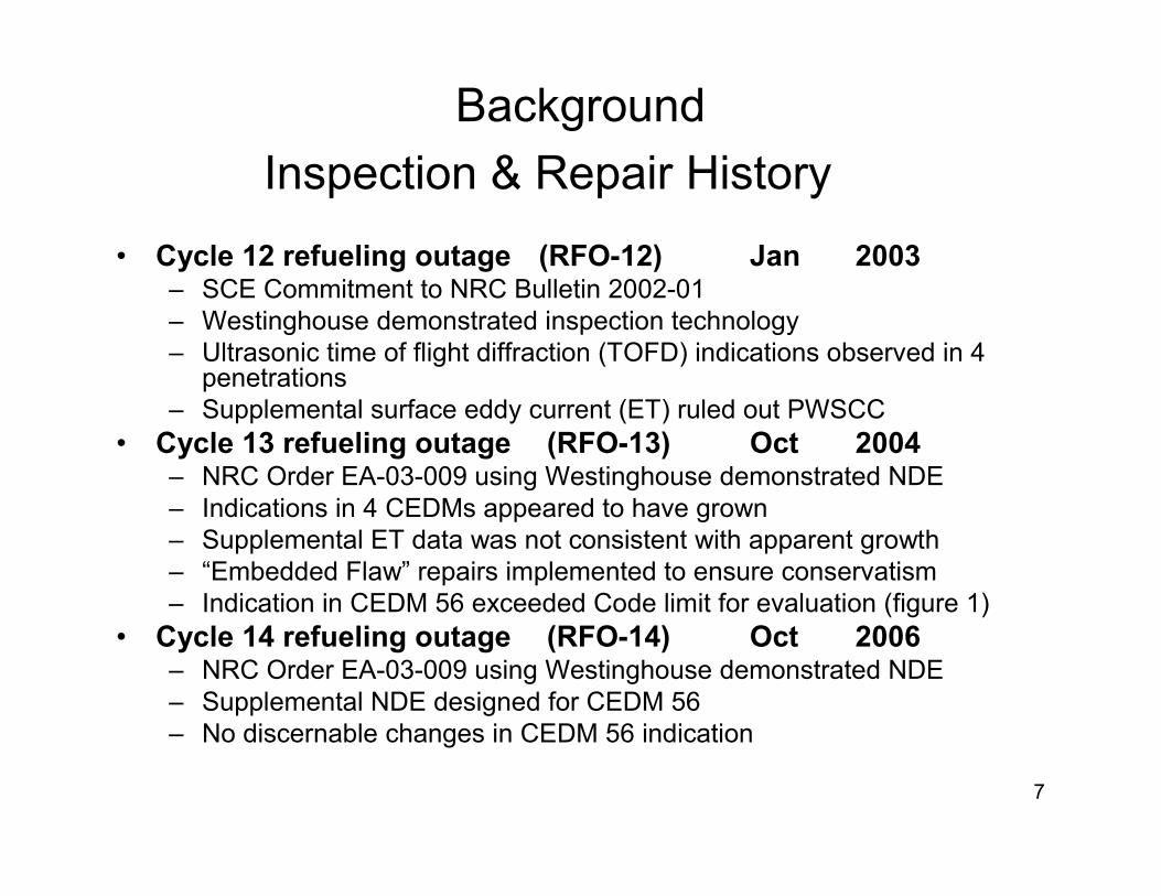
Background
Inspection & Repair History
• Cycle 12 refueling outage (RFO-12) Jan 2003– SCE Commitment to NRC Bulletin 2002-01– Westinghouse demonstrated inspection technology– Ultrasonic time of flight diffraction (TOFD) indications observed in 4
penetrations– Supplemental surface eddy current (ET) ruled out PWSCC
• Cycle 13 refueling outage (RFO-13) Oct 2004– NRC Order EA-03-009 using Westinghouse demonstrated NDE– Indications in 4 CEDMs appeared to have grown – Supplemental ET data was not consistent with apparent growth– “Embedded Flaw” repairs implemented to ensure conservatism– Indication in CEDM 56 exceeded Code limit for evaluation (figure 1)
• Cycle 14 refueling outage (RFO-14) Oct 2006– NRC Order EA-03-009 using Westinghouse demonstrated NDE– Supplemental NDE designed for CEDM 56– No discernable changes in CEDM 56 indication

8
BackgroundFigure 1
CEDM 56 Indication Profile
9
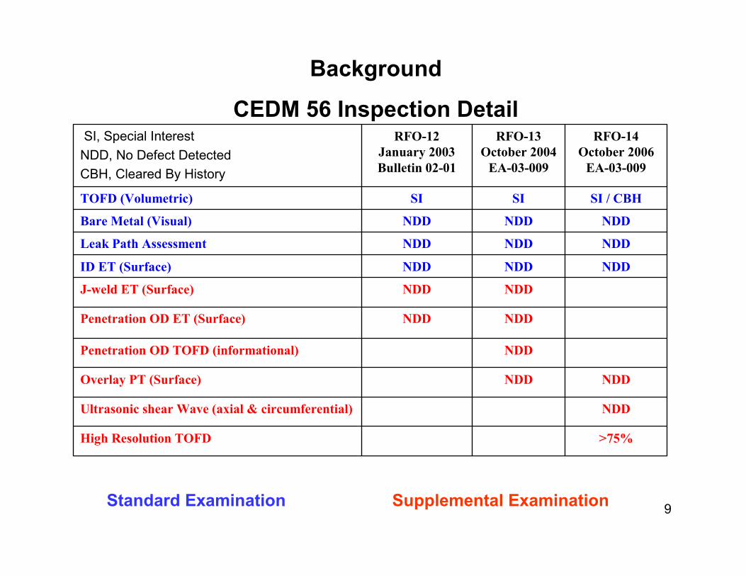
>75%High Resolution TOFD
NDDUltrasonic shear Wave (axial & circumferential)
NDDNDDOverlay PT (Surface)
NDDPenetration OD TOFD (informational)
NDDNDDPenetration OD ET (Surface)
NDD NDDJ-weld ET (Surface)
NDDNDDNDDID ET (Surface)
NDDNDDNDDLeak Path Assessment
NDDNDDNDDBare Metal (Visual)
SI / CBHSISITOFD (Volumetric)
RFO-14October 2006
EA-03-009
RFO-13October 2004
EA-03-009
RFO-12January 2003Bulletin 02-01
SI, Special Interest
NDD, No Defect Detected
CBH, Cleared By History
Background
CEDM 56 Inspection Detail
Standard Examination Supplemental Examination
10
Evaluation
• Approach
• Determination of No Growth
• Inconsistent with Primary Water Stress Corrosion Cracking (PWSCC)
• Review of Industry Experience

11
Evaluation Approach
• WesDyne (Westinghouse)– Perform a consistent evaluation of base scope NDE data for
indications of growth in CEDM 56 (and CEDMs 32, 57, and 64) from RFO 12, 13, and 14
– Assess supplemental NDE data from CEDM 56 to determine possibility of a PWSCC flaw
– Evaluation and assessment performed by• Level III with extensive experience in RVH TOFD• Chief Engineer, recognized authority in NDE
• ANATEC – Third party review of NDE data and Westinghouse evaluation
• Level III with extensive experience in RVH TOFD• Concluded not attributable to PWSCC
• SONGS Engineering – Analysis, review, oversight, and ownership of results
12
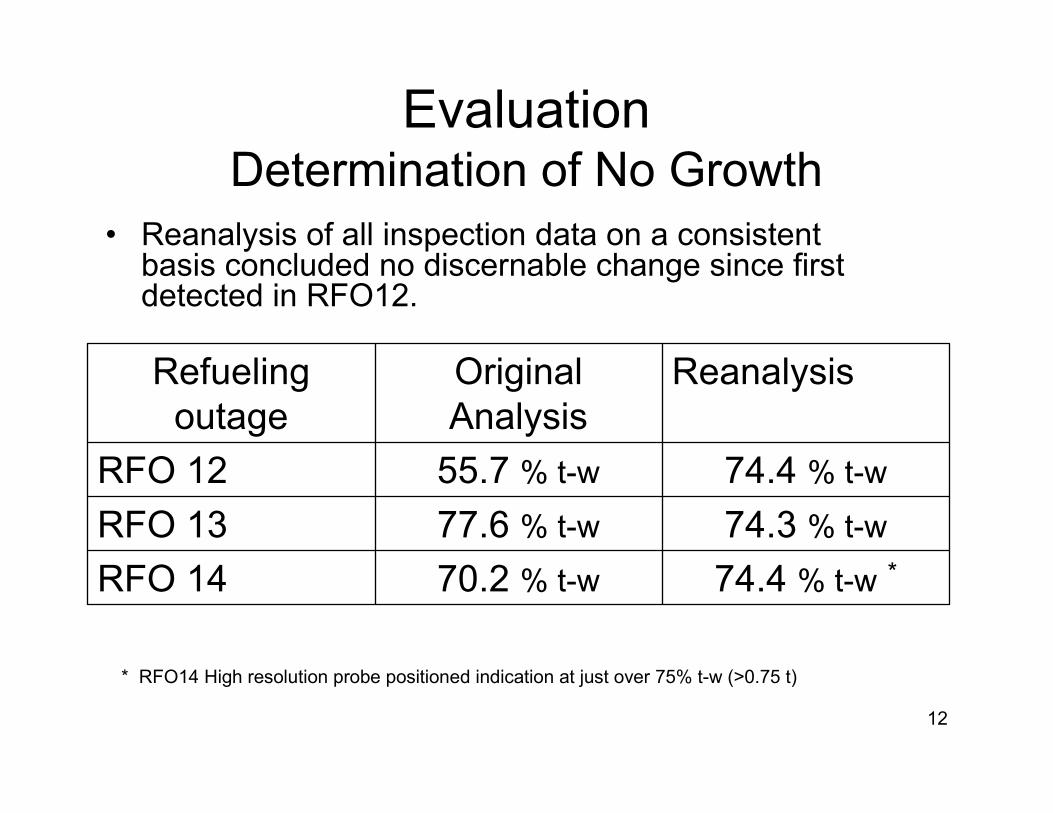
EvaluationDetermination of No Growth
• Reanalysis of all inspection data on a consistent basis concluded no discernable change since first detected in RFO12.
74.4 % t-w *70.2 % t-wRFO 14
74.3 % t-w77.6 % t-wRFO 13
74.4 % t-w55.7 % t-wRFO 12
ReanalysisOriginal Analysis
Refueling outage
* RFO14 High resolution probe positioned indication at just over 75% t-w (>0.75 t)
13
EvaluationInconsistent with PWSCC
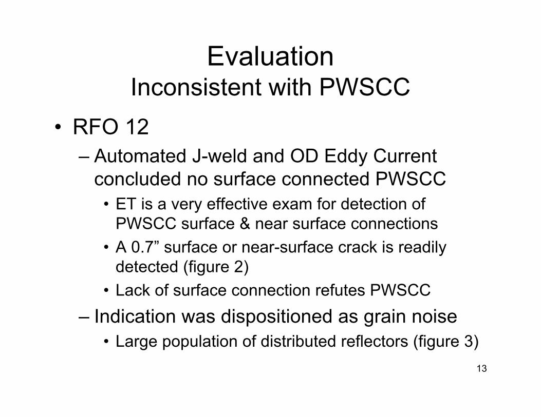
• RFO 12 – Automated J-weld and OD Eddy Current
concluded no surface connected PWSCC• ET is a very effective exam for detection of
PWSCC surface & near surface connections
• A 0.7” surface or near-surface crack is readily detected (figure 2)
• Lack of surface connection refutes PWSCC
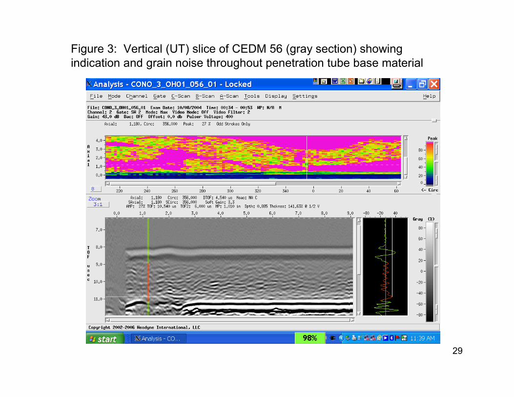
– Indication was dispositioned as grain noise• Large population of distributed reflectors (figure 3)

14
Evaluation Inconsistent with PWSCC
• RFO 13– Manual OD scan employing TOFD & ET
(informal)• ET: No crack like features
• TOFD: No lateral wave interruption
– J-weld ET: No crack like features
– No effect from repair on ID exam
15
Evaluation Inconsistent with PWSCC
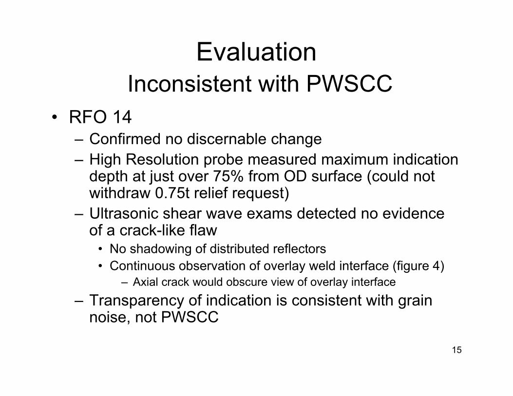
• RFO 14– Confirmed no discernable change– High Resolution probe measured maximum indication
depth at just over 75% from OD surface (could not withdraw 0.75t relief request)
– Ultrasonic shear wave exams detected no evidence of a crack-like flaw
• No shadowing of distributed reflectors• Continuous observation of overlay weld interface (figure 4)
– Axial crack would obscure view of overlay interface
– Transparency of indication is consistent with grain noise, not PWSCC
16
EvaluationReview of Industry Experience
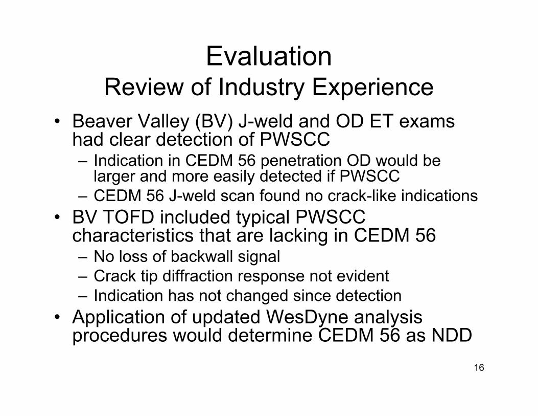
• Beaver Valley (BV) J-weld and OD ET exams had clear detection of PWSCC– Indication in CEDM 56 penetration OD would be
larger and more easily detected if PWSCC– CEDM 56 J-weld scan found no crack-like indications
• BV TOFD included typical PWSCC characteristics that are lacking in CEDM 56– No loss of backwall signal– Crack tip diffraction response not evident– Indication has not changed since detection
• Application of updated WesDyne analysis procedures would determine CEDM 56 as NDD

17
EvaluationTechnical Summary
• Ultrasonic TOFD (tip diffraction) technology is very sensitive, and commonly detects normal material structures in addition to real defects
– Real cracks affect TOFD inspection results in a predictable way• Backwall reflections should be suppressed over certain angles• Distributed reflectors should be obscured behind crack faces • Characteristic tip diffraction signal response
– CEDM 56 penetration includes TOFD features typical of grain noise, and not PWSCC
• Confirmed growth in a TOFD indication over time is compelling evidence of PWSCC
– Uniform analysis of RFO 12, 13, and 14 examination data has concluded that no discernable change in indication has actually occurred
• Supplemental NDE is standard practice for validating TOFD indications– Eddy Current is a reliable confirmatory test for PWSCC surface connection.
Supplemental ET of J-weld & Penetration OD in RFO 12 and 13 refuted PWSCC hypothesis.
– There was no shear wave obscuration of backwall features or distributed reflectors which would be expected behind a crack face
18
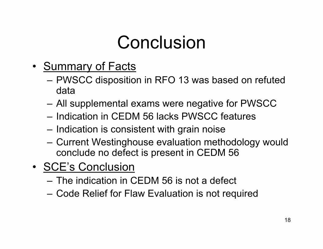
Conclusion• Summary of Facts
– PWSCC disposition in RFO 13 was based on refuted data
– All supplemental exams were negative for PWSCC– Indication in CEDM 56 lacks PWSCC features– Indication is consistent with grain noise – Current Westinghouse evaluation methodology would
conclude no defect is present in CEDM 56
• SCE’s Conclusion– The indication in CEDM 56 is not a defect – Code Relief for Flaw Evaluation is not required

19
Future Plans
• Continue with EA-03-009 examinations every refueling outage
• Respond to any new indications or unexpected changes as appropriate
• Replace the SONGS 3 Reactor Vessel Head during RFO 17
(approximately Fall of 2012)

20
Licensing
Licensing correspondence associated with CEDM 56

21
• Relief Request ISI-3-8: – Contingency submitted prior to RFO 13
“Embedded Flaw” Repair (< 75% t-w) --Used for 3 CEDMs during RFO 13
• Submitted December 3, 2003
• Supplemented March 15, 2004
• Approved May 5, 2004
• No Commitments made at this time
Licensing

22
Licensing
• Relief Request ISI-3-13: – Submitted during RFO 13 “Embedded Flaw”
Repair (>75% t-w) Specifically for CEDM 56• Submitted October 26, 2004
• Supplemented December 2, 2004*
• Approved December 23, 2004
• *Commitment: SCE will identify a long-term repair method and implement that repair in RFO 14

23
Licensing
• Meeting with NRC Staff:– March 2, 2006, presented long term disposition
of CEDM 56– Existing repair is adequate for one cycle– SCE will inspect to validate stability– SCE will submit 2 relief requests
• If no discernable growth – Operate 1 cycle (ISI-3-21)• Contingency repair alternative (ISI-3-22)
• Teleconference with NRC Staff– March 22, 2006, agreed to above approach

24
Licensing• Relief Request ISI-3-21: Allowing 1 cycle of
operation contingent upon no discernable growth (<0.02”)– Submitted May 11, 2006 (Prior to RFO 14)
– Teleconference November 14, 2006 (During RFO 14)*
– Supplemented November 20, 2006 (During RFO 14)**
– Verbal Approval December 1, 2006 (During RFO 14)
– Written Approval February 7, 2007
* SCE informed NRC no discernable growth
** Commitment: SCE to either reclassify as NDD and withdraw Relief Requests ISI-3-21 and ISI-3-22 or will repair during RFO 15

25
Licensing
• Relief Request ISI-3-22: Contingency repair in RFO 14 to allow operation to RFO 15 if growth was greater than or equal to 0.02” (no discernable growth)

26
Licensing
• Based on all information available to date, SCE reclassified the indication in CEDM 56 as NDD– August 31, 2007, SCE documented
completion of NDE evaluation and withdrew Relief Request ISI-3-21

27
Questions

28Beaver Valley OD CEDM 56
Figure 2: Comparison of penetration tube ET results for OD PWSCC
29
Figure 3: Vertical (UT) slice of CEDM 56 (gray section) showingindication and grain noise throughout penetration tube base material

30
Figure 4: Unobstructed detection of OD weld overlay interface on CEDM 56
70° /40° circumferential shear wave UT analysis of CEDM 56
Overlay weld interface