September 2012 Types C471 and C477 jet Bleed Internal Valves … · 2017-09-12 · Bulletin...
8
Bulletin LP-7:C471/C477 D450244T012 September 2012 www.fisherregulators.com Types C471 and C477 Jet Bleed Internal ™ Valves Features • Patented rapid equalization bleed area – Provides fast valve response for quick opening. • Unique Serviceability Features – Stainless trim parts and poppet designed with integral wrench flat for easy maintenance. • Durable Design – Stainless poppet and stem interface smoothly for a long wear life. • Excess Flow Closure – Functions when flow exceeds the valves rated capacity or piping is sheared off at the valve. Figure 1. Types C471 and C477 Jet Bleed Internal ™ Valves Introduction Types C477 and C471 Jet Bleed Internal ™ Valves are designed to provide rapid equalization of tank pressure and downstream line pressure, providing a fast valve response time for quick valve opening. These may be used as primary shutoff valves, excess flow valves, and back check valves for Propane, Butane, and NH 3 (anhydrous ammonia) transfers between stationary bulk storage tanks and mobile transports for fill or delivery applications of liquid or vapor gas, and on in-line applications. The valves can be used in installations with or without pumps and compressors. Non Underwriters Laboratories (UL ® ) listed types are available with a variety of trim types and body styles and can be used on other compressed gases, but the user should check with the factory to make sure the valves are suitable for the particular service. Actuation of the valve can be achieved manually, by cable, or with a pneumatic actuator. • Back Check Feature – Allows reverse flow, fill with or without actuator device in valve open position. • Spring loaded polytetrafluoroethylene (pTFe) stub shaft packing. • PTFE wear pads Rulon ® Bushings at critical wear points • Manual, Cable, or Air Open/Close valve actuators. • Thermal Fusible links or plugs melt at 212 to 220°F / 100 to 104°C and allow valve closure in the event of a fire at the valve. Rulon ® is a Trademark of Saint-Gobain Performance Plastics Corporation. Type C477 Type C471
-
Upload
duonghuong -
Category
Documents
-
view
213 -
download
0
Transcript of September 2012 Types C471 and C477 jet Bleed Internal Valves … · 2017-09-12 · Bulletin...
Bulletin LP-7:C471/C477
D45
0244
T012
September 2012
www.fisherregulators.com
Types C471 and C477 jet Bleed Internal™ Valves
Features
• Patented rapid equalization bleed area – Provides fast valve response for quick opening.
• unique Serviceability Features – Stainless trim parts and poppet designed with integral wrench fl at for easy maintenance.
• Durable Design – Stainless poppet and stem interface smoothly for a long wear life.
• Excess Flow Closure – Functions when fl ow exceeds the valves rated capacity or piping is sheared off at the valve.
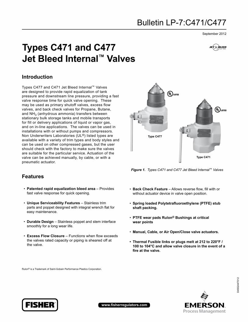
Figure 1. Types C471 and C477 Jet Bleed Internal™ Valves
Introduction
Types C477 and C471 Jet Bleed Internal™ Valves are designed to provide rapid equalization of tank pressure and downstream line pressure, providing a fast valve response time for quick valve opening. These may be used as primary shutoff valves, excess flow valves, and back check valves for Propane, Butane, and NH3 (anhydrous ammonia) transfers between stationary bulk storage tanks and mobile transports for fill or delivery applications of liquid or vapor gas, and on in-line applications. The valves can be used in installations with or without pumps and compressors. Non Underwriters Laboratories (UL®) listed types are available with a variety of trim types and body styles and can be used on other compressed gases, but the user should check with the factory to make sure the valves are suitable for the particular service. Actuation of the valve can be achieved manually, by cable, or with a pneumatic actuator.
• Back Check Feature – Allows reverse fl ow, fi ll with or without actuator device in valve open position.
• Spring loaded polytetrafl uoroethylene (pTFe) stub shaft packing.
• PTFE wear pads Rulon® Bushings at critical wear points
• Manual, Cable, or Air Open/Close valve actuators.
• Thermal Fusible links or plugs melt at 212 to 220°F / 100 to 104°C and allow valve closure in the event of a fi re at the valve.
Rulon® is a Trademark of Saint-Gobain Performance Plastics Corporation.
Type C477
Type C471

Bulletin LP-7:C471/C477
2
1. The pressure/temperature limits in this Bulletin and any applicable standard or code limitation should not be exceeded.2. Product has passed Fisher® testing for leakage down to -40ºF / -40ºC. Kalrez® is a mark owned by E.I. du Pont de Nemours and Co.
Specifications
Body Size and End Connection Style
Inlet: 2 or 3-inch MNPT / DN 50 or 80 Outlet: 2 or 3-inch FNPT / DN 50 or 80
Number of Outlets
Type C471: 2 (side and straight through) Type C477: 1 (straight through)
Excess Flow Springs
Half Coupling Flows: 2-inch Sizes / DN 50: 105, 150, and 250 GPM /
397, 567, and 946 L/min 3-inch Sizes / DN 80: 160, 265, 375, and 460 GPM /
605, 1003, 1419, and 1741 L/min Full Coupling Flows: 2-inch Sizes / DN 50: 60, 80, and 130 GPM / 227, 302, and 492 L/min 3-inch Sizes / DN 80: 120, 230, 320, and 380 GPM /
454, 870, 1211, and 1438 L/min
Maximum Allowable Inlet Pressure(1)
400 psig / 27.6 bar WOG
Temperature Capabilities(1)(2)
-20 to 150°F / -29 to 66°C
Construction Materials
Steel Body and Operating Lever
Stainless steel
Stem Assembly, Excess Flow Spring, Spring Seat, Closing Spring, Disc Holder, Disc Retainer, Screw, O-ring Seat, O-ring Retainer, Cotter Pin, Spring, Shaft, Screen, Travel Stop, Screen Cap, Bolt, Gasket, and Lock Washer
Plated steel Nut, Washer, Bonnet Nut, Guide Bracket, and Cap Screw
Polyurethane Rod Wiper
PTFE Bushing, Packing Adaptor, and Packing Ring
Nitrile (NBR) (Standard Construction)
Main Disc and Bleed Disc
Other Disc and O-ring Material Available from Factory
PTFE, Fluorocarbon (FKM), Neoprene (CR), Ethylene-Propylene (EPDM), and Kalrez®
Closing Flow and Vapor Capacity
See Table 2
Approximate Weights
2-inch Sizes / DN 50: Type C471: 11 pounds / 5 kg Type C477: 9 pounds / 4 kg
3-inch Sizes / DN 80: Type C471: 21 pounds / 10 kg Type C477: 16 pounds / 7 kg

Bulletin LP-7:C471/C477
3
Figure 2. Typical Operational Schematic
Principle of Operation Refer to the operational schematic, Figure 2. In view #1, the valve is held closed by both tank pressure and the valve’s closing spring. There is no leakage past the resilient seats in the poppet to the valve outlet. The valve is opened by moving the operating lever to approximately midpoint in its 70° travel (view #2). This allows the cam to place the rapid equalization portion of the valve stem in the pilot opening, permitting a larger amount of product to bleed downstream than if the operating lever were moved to the full open position. When tank and downstream pressure are nearly equal after a few seconds, the excess flow spring pushes open the main poppet (view #3) and the operating lever can be moved to the full open position.
Note
If tank pressure is greater than the valve’s outlet pressure, the main poppet will remain in the closed position. If valve outlet piping
is closed off by other valves, however, product bleeding through the pilot will increase until it nearly equals tank pressure and the main poppet opens. The main poppet will not open if valve outlet piping is not closed off so that the outlet pressure can approach tank pressure.
Once the main poppet opens, a flow greater than the valve’s excess flow spring rating or a sufficient surge in flow forces the main poppet closed against the excess flow spring (view #4). The pilot valve allows a small amount of product to bleed, but much less than view #2 where the rapid equalization portion of the stem is placed in the pilot opening. When the operating lever is moved to the closed position, the valve closes completely and seals tightly (view #1).
LIMITED BLEEDVALVE OPEN FLOWjET BLEED EquALIzATION
VALVE CLOSED1 2 3 4jET BLEED OPEN VALVE OPEN ExCESS FLOW VALVE CLOSED
jETBLEED
jETBLEED
FLOWLIMITED
BLEEDLIMITED BLEEDFLOW
M1170

Bulletin LP-7:C471/C477
4
MODEL NuMBER SIzE SPRING RATE
ExAMPLE: C 4 7 1 N - 24 - 26
Symbol Description
C Product Family
4 UL® Listed
8 Non UL® Listed
7 Ductile Iron Body
8 Steel Body
9 Stainless Body
7 Straight Through Flow
3 Double Flanged Body
4 Single Flanged Body
1 Tee Body (Flanged and NPT)
Nitrile (NBR) (Standard, Only Nitrile (NBR) has UL® Approval)
V Fluorocarbon (FKM) Trim
T PTFE Trim
N Neoprene (CR) Trim
S Stainless Steel Body/Gland*
M Manual Latch Factory Installed
ST Stainless steel Gland and PTFE Trim
10 1-1/4-Inch / DN 32
16 2-Inch / DN 50
24 3-Inch / DN 80
32 4-Inch / DN 100
10 105 GPM / 397 L/min
15 150 GPM / 568 L/min
16 160 GPM / 606 L/min
22 220 GPM / 833 L/min
25 250 GPM / 946 L/min
26 265 GPM / 1003 L/min
37 375 GPM / 1419 L/min
46 460 GPM / 1741 L/min
Figure 3. Fisher® Internal Valve Numbering System
* The Type C891 has Stainless steel body as Standard. ‘S’ callout on a Type C891 stands for a Stainless steel Gland. For each product family, not all options are available. To check the availability of type numbers specified above, contact or visit your local LP-Gas Equipment distributor.

Bulletin LP-7:C471/C477
5
Table 1. Closing Flow - Propane and NH3
SIzE
TYPE NuMBER CLOSING FLOW GPM / L/min PROPANE CLOSING FLOW GPM / L/min NH3
Straight Body Tee BodyHalf Coupling, Bottom of Tank
Position*
Full Coupling, Bottom of Tank
Position*
Half Coupling, Top of Tank Position*
Half Coupling, Bottom of Tank
Position*
2-inch / DN 50C477-16-10 C471-16-10 105 / 397 60 / 227 120 / 454 95 / 360C477-16-15 C471-16-15 150 / 568 80 / 303 170 / 643 135 / 511C477-16-25 C471-16-25 250 / 946 130 / 492 250 / 946 226 / 855
3-inch / DN 80
C477-24-16 C471-24-16 160 / 606 120 / 454 180 / 681 145 / 549C477-24-26 C471-24-26 265 / 1003 230 / 871 290 / 1098 239 / 905C477-24-37 C471-24-37 375 / 1419 320 / 1211 395 / 1495 339 / 1283C477-24-46 C471-24-46 460 / 1741 380 / 1438 460 / 1741 415 / 1571
* See Internal Valve Flow Positions (Figure 4) for description of Bottom of Tank, Top of Tank, and Horizontal Flow Positions.
Figure 4. Internal Valve Flow Positions
IN-LINE ADAPTOR
IN-LINE ADAPTORS
zDimensions, Inches / mm
x Y D
1-1/4-inch FNPT / DN 32 4.70 / 119 2.75 / 70 2.05 / 52
2-inch FNPT / DN 50 6.77 / 172 3.5 / 89 2.80 / 71
3-inch FNPT / DN 80 7.53 / 191 4.5 / 114 3.80 / 97
D z
x
Y
FLOWFLOW
HORIzONTAL POSITION(iN-liNe pipiNg)
BOTTOM OF TANk POSITION TOP OF TANk POSITION
TANk
TANkFLOW
FLOW
FLOW
Table 2. Closing Flow and Vapor Capacity
SIzESTYLE VAPOR CAPACITY SCFH / SCMH PROPANE
Straight Body Tee Body 100 psig / 6.90 bar inlet, Bottom of Tank Position*
100 psig / 6.90 bar inlet, Horizontal Position*
100 psig / 6.90 bar inlet, Top of Tank Position*
2-inch /DN 50
C477-16-10 C471-16-10 45,000 / 1274 49,000 / 1388 66,000 / 1869C477-16-15 C471-16-15 69,000 / 1954 69,000 / 1954 88,000 / 2492C477-16-25 C471-16-25 NOT LISTED NOT LISTED NOT LISTED
3-inch /DN 80
C477-24-16 C471-24-16 71,000 / 2011 71,000 / 2011 96,000 / 2718C477-24-26 C471-24-26 127,000 / 3596 127,000 / 3596 148,000 / 4191C477-24-37 C471-24-37 178,000 / 5040 178,000 / 5040 186,000 / 5267C477-24-46 C471-24-46 NOT LISTED NOT LISTED NOT LISTED
* See Internal Valve Flow Positions (Figure 4) for description of Bottom of Tank, Top of Tank, and Horizontal Flow Positions.

Bulletin LP-7:C471/C477
6
4
6
8
10
12
14
16
18
20
0 50 100 150 200 250 300
Valv
eD
ifffffefef
rerernt
ialP
rererss
urerer
,psi
g
Flow GPM Propane
2.3671
72
222 494
2
11111.3333322222555
2222.555511144
VV VV aV aVa aa ll ll
vl vlv vv ev eve ee
DD DDii ii fi fif ff ff fff fffff ffff ffff ff ff ff
ef efe eefef efef feff ff ef ffrr rr er ere eerer erer rerr rr er rr
nn nn tn tnt tt it iti ii ai aia aa
ll ll PP PP r
r rr er ere eerer erer rerr rr er rrse ses ss
ss sss ssuu uu r
r rr er ere eerer erer rerr rr er rr,e ,e, ,,
pp pp sp sps ss i
i ii gi gig ggp
Unit 1
UUUnit 3
C477-16-25 Vertical Up PositionVA
LVE
DIF
FER
ENTI
AL
PRES
SuR
E, p
sig
/ bar
20 /1.4
18 /1.2
16 /1.1
14 /0.97
12 /0.83
10 /0.69
8 /0.55
6 / 0.41
4 /0.28
2 /0.14
0100 /379
50 /189
150 /568
200 /757
250 /946
300 /1136
FLOW RATE, GPM / L/min PROPANE
Figure 5. Type C477/471-16 Bottom of Tank Position Flow Curve, Half Coupling
0
C477-16-25 Vertical Up Position
105 gpM / 397 L/min Rating150 gpM / 567 L/min Rating250 gpM / 946 L/min Rating
Figure 6. Type C477/471-24 Bottom of Tank Position Flow Curve, Half Coupling
2
4
6
8
10
12
14
16
18
20
50 200 250 300 350 400
Valv
eD
ifffffefef
rerernt
ialP
rererss
urerer
,psi
g
Flow GPM Propane
1.3251111.888888883333
2.5114
V VV Va Va Vaa al al a
v lv lvv ve ve vee e
D DD Di Di Df if iff ff ff fff fffff ffffff ff ff ff f
e fe fee efefe fefff fe ff fr er err re re ree erere rerrer rr re rr r
n en enn nt nt ntt ti ti ta ia iaa a
l al aP PP Pr Pr P
rr re re ree erere rerrer rr re rr rs es ess s
s ss sss su su suu u
r ur urr re re ree erere rerrer rr re rr r
, e, ep pp ps ps p
ss si si sg ig igg g
Unit 1Unit 1
UUniitt 33
C477-24-36Vertical Up Position
50 /189
150 /568
200 /757
250 /946
300 /1136
350 /1325
400 /1514
100 /379
00
20 /1.4
18 /1.2
16 /1.1
14 /0.97
12 /0.83
10 /0.69
8 /0.55
6 /0.41
4 /0.28
2 /0.14
VALV
E D
IFFE
REN
TIA
L PR
ESSu
RE,
psi
g / b
ar
FLOW RATE, GPM / L/min PROPANE
C477-24-36Vertical Up Position
160 gpM / 605 L/min Rating265 gpM / 1003 L/min Rating375 gpM / 1419 L/min Rating460 gpM / 1741 L/min Rating
450 /1703

Bulletin LP-7:C471/C477
7
Figure 7. Type C477-24 Typical Reverse Flow Curve
650 /2460
600 /2271
0 50 /189
FLOW RATE, GPM / L/min PROPANE
VALV
E D
IFFE
REN
TIA
L PR
ESSu
RE,
psi
g / b
ar
Valve Closed Position
Valve Open Position
40 /2.8
0
35 /2.4
30 /2.125 /1.7
20 /1.4
15 /1.010 /0.695 /0.35
100 /379
150 /568
200 /757
250 /946
300 /1136
550 /2082
450 /1703
400 /1514
350 /1325
500 /1893
700 /2650
FLOW RATE, GPM / L/min PROPANE
VALV
E D
IFFE
REN
TIA
L PR
ESSu
RE,
psi
g / b
ar
Figure 8. Type C477-16 Typical Reverse Flow Curve
55 / 3.8
50 / 3.4
45 / 3.1
40 / 2.8
35 / 2.4
30 / 2.1
25 / 1.7
20 / 1.4
15 / 1.0
10 / 0.69
5 / 0.35
0 0 50 /
189100 /379
150 /568
200 /757
250 /946
300 /1136
350 /1325
Valve Open Position
Valve Closed Position
Figure 9. Dimensions
Table 3. Dimensions
TYPE NuMBER
A, INCH FNPT / DN
B, INCH MNPT / DN
DIMENSIONS, INCHES / mm
C D E F H INSTALLATION CLEARANCE DIAMETER
C471-16 2 / 50 2 / 50 8.07 / 205 2.40 / 61 4.05 / 103 2.76 / 70 2.66 / 68 10.00 / 254C471-24 3 / 80 3 / 80 9.00 / 229 2.60 / 66 4.57 / 116 3.25 / 83 3.26 / 83 13.38 / 340C477-16 2 / 50 2 / 50 8.07 / 205 2.40 / 61 4.05 / 103 - - - - - - - - 10.00 / 254C477-24 3 / 80 3 /80 9.00 / 229 2.60 / 66 4.57 / 116 - - - - - - - - 13.38 / 340
70°SWING
A-FNPT
APPROxIMATE TOPOF BOSS OR COuPLING
B-MNPT
1/4-INCHC
D
E
B - MNPT
APPROxIMATE TOP OF BOSS OR COuPLINGC
CLOSED
E
A - FNPT
70°SWING
D
A - FNPTF
H
1/4-INCH FNPT
C477 SERIES
C471 SERIES

Bulletin LP-7:C471/C477
©Emerson Process Management Regulator Technologies, Inc., 2010, 2012; All Rights Reserved
The Emerson logo is a trademark and service mark of Emerson Electric Co. All other marks are the property of their prospective owners. Fisher is a mark owned by Fisher Controls, International LLC., a business of Emerson Process Management.
The contents of this publication are presented for informational purposes only, and while every effort has been made to ensure their accuracy, they are not to be construed as warranties or guarantees, express or implied, regarding the products or services described herein or their use or applicability. We reserve the right to modify or improve the designs or specifications of such products at any time without notice.
Emerson Process Management Regulator Technologies Inc., does not assume responsibility for the selection, use or maintenance of any product. Responsibility for proper selection, use and maintenance of any Emerson Process Management Regulator Technologies, Inc. product remains solely with the purchaser.
LP-Gas Equipment
Emerson Process Management Regulator Technologies, Inc. USA - HeadquartersMcKinney, Texas 75069-1872 USATelephone: 1 (800) 558-5853Telephone: 1 (972) 548-3574
For further information visit www.fisherregulators.com
SIzETYPE NuMBER FLANGE CONNECTION SIzE, INCHES ACTuATION METHOD AND DEVICE
Straight Body Tee Body Inlet Outlet Air Manual with Thermal Latch
2-inch /DN 50
C477-16-10 C471-16-10
2-inch MNPT / DN 50
2-inch FNPT / DN 50 (Straight) 2 x 2-inch FNPT /
DN 50 x 50 (Tee Body)
Type P639 Type P340C477-16-15 C471-16-15
C477-16-25 C471-16-25
3-inch /DN 80
C477-24-16 C471-24-16
3-inch MNPT / DN 80
3-inch FNPT / DN 80 (Straight) 2 x 3-inch FNPT /
DN 50 x 80 (Tee Body)
Type P639 Type P340C477-24-26 C471-24-26
C477-24-37 C471-24-37
C477-24-46 C471-24-46
Please Contact Your Local LP-Gas Equipment Distributor for Availability of Non-Standard Options.
Ordering InformationTo order, refer to the table below and specify the type number that satisfies your requirement. Then, contact or visit your local LP-Gas Equipment Distributor for availability.