September 15 Type SR5 Sanitary Pressure Regulator · Type SR5 D1399X1 instruction Manual Form 576...
12
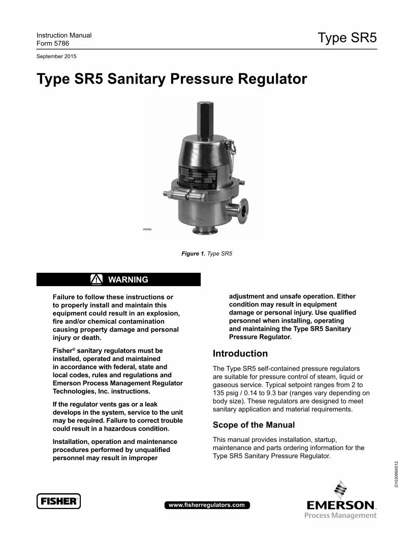
Type SR5 D103099X012 Instruction Manual Form 5786 September 2015 www.fisherregulators.com Type SR5 Sanitary Pressure Regulator Figure 1. Type SR5 ! WARNING Failure to follow these instructions or to properly install and maintain this equipment could result in an explosion, fire and/or chemical contamination causing property damage and personal injury or death. Fisher ® sanitary regulators must be installed, operated and maintained in accordance with federal, state and local codes, rules and regulations and Emerson Process Management Regulator Technologies, Inc. instructions. If the regulator vents gas or a leak develops in the system, service to the unit may be required. Failure to correct trouble could result in a hazardous condition. Installation, operation and maintenance procedures performed by unqualified personnel may result in improper W8966 adjustment and unsafe operation. Either condition may result in equipment damage or personal injury. Use qualified personnel when installing, operating and maintaining the Type SR5 Sanitary Pressure Regulator. Introduction The Type SR5 self-contained pressure regulators are suitable for pressure control of steam, liquid or gaseous service. Typical setpoint ranges from 2 to 135 psig / 0.14 to 9.3 bar (ranges vary depending on body size). These regulators are designed to meet sanitary application and material requirements. Scope of the Manual This manual provides installation, startup, maintenance and parts ordering information for the Type SR5 Sanitary Pressure Regulator.
Transcript of September 15 Type SR5 Sanitary Pressure Regulator · Type SR5 D1399X1 instruction Manual Form 576...
Type SR5
D10
3099
X01
2
Instruction ManualForm 5786
September 2015
www.fisherregulators.com
Type SR5 Sanitary Pressure Regulator
Figure 1. Type SR5
! WaRning
Failure to follow these instructions or to properly install and maintain this equipment could result in an explosion, fire and/or chemical contamination causing property damage and personal injury or death.
Fisher® sanitary regulators must be installed, operated and maintained in accordance with federal, state and local codes, rules and regulations and Emerson Process Management Regulator Technologies, inc. instructions.
if the regulator vents gas or a leak develops in the system, service to the unit may be required. Failure to correct trouble could result in a hazardous condition.
installation, operation and maintenance procedures performed by unqualified personnel may result in improper
W8966
adjustment and unsafe operation. Either condition may result in equipment damage or personal injury. Use qualified personnel when installing, operating and maintaining the Type SR5 Sanitary Pressure Regulator.
introductionThe Type SR5 self-contained pressure regulators are suitable for pressure control of steam, liquid or gaseous service. Typical setpoint ranges from 2 to 135 psig / 0.14 to 9.3 bar (ranges vary depending on body size). These regulators are designed to meet sanitary application and material requirements.
Scope of the ManualThis manual provides installation, startup, maintenance and parts ordering information for the Type SR5 Sanitary Pressure Regulator.
Type SR5
2
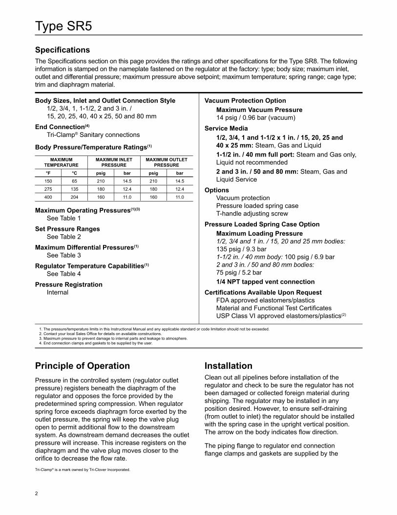
SpecificationsThe Specifications section on this page provides the ratings and other specifications for the Type SR8. The following information is stamped on the nameplate fastened on the regulator at the factory: type; body size; maximum inlet, outlet and differential pressure; maximum pressure above setpoint; maximum temperature; spring range; cage type; trim and diaphragm material.
Body Sizes, inlet and Outlet Connection Style1/2, 3/4, 1, 1-1/2, 2 and 3 in. / 15, 20, 25, 40, 40 x 25, 50 and 80 mm
End Connection(4)
Tri-Clamp® Sanitary connections
Body Pressure/Temperature Ratings(1)
MaXiMUM TEMPERaTURE
MaXiMUM inLET PRESSURE
MaXiMUM OUTLET PRESSURE
°F °C psig bar psig bar
150 65 210 14.5 210 14.5
275 135 180 12.4 180 12.4
400 204 160 11.0 160 11.0
Maximum Operating Pressures(1)(3)
See Table 1Set Pressure Ranges
See Table 2 Maximum Differential Pressures(1)
See Table 3Regulator Temperature Capabilities(1)
See Table 4Pressure Registration
Internal
Vacuum Protection OptionMaximum Vacuum Pressure14 psig / 0.96 bar (vacuum)
Service Media1/2, 3/4, 1 and 1-1/2 x 1 in. / 15, 20, 25 and 40 x 25 mm: Steam, Gas and Liquid1-1/2 in. / 40 mm full port: Steam and Gas only, Liquid not recommended2 and 3 in. / 50 and 80 mm: Steam, Gas and Liquid Service
OptionsVacuum protectionPressure loaded spring caseT-handle adjusting screw
Pressure Loaded Spring Case OptionMaximum Loading Pressure1/2, 3/4 and 1 in. / 15, 20 and 25 mm bodies: 135 psig / 9.3 bar1-1/2 in. / 40 mm body: 100 psig / 6.9 bar2 and 3 in. / 50 and 80 mm bodies: 75 psig / 5.2 bar1/4 NPT tapped vent connection
Certifications Available Upon RequestFDA approved elastomers/plasticsMaterial and Functional Test CertificatesUSP Class VI approved elastomers/plastics(2)
1. The pressure/temperature limits in this Instructional Manual and any applicable standard or code limitation should not be exceeded.2. Contact your local Sales Office for details on available constructions.3. Maximum pressure to prevent damage to internal parts and leakage to atmosphere.4. End connection clamps and gaskets to be supplied by the user.
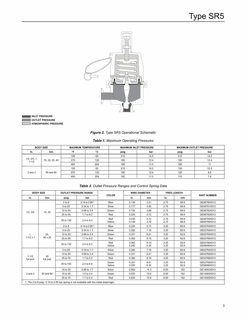
Principle of OperationPressure in the controlled system (regulator outlet pressure) registers beneath the diaphragm of the regulator and opposes the force provided by the predetermined spring compression. When regulator spring force exceeds diaphragm force exerted by the outlet pressure, the spring will keep the valve plug open to permit additional flow to the downstream system. As downstream demand decreases the outlet pressure will increase. This increase registers on the diaphragm and the valve plug moves closer to the orifice to decrease the flow rate.
installationClean out all pipelines before installation of the regulator and check to be sure the regulator has not been damaged or collected foreign material during shipping. The regulator may be installed in any position desired. However, to ensure self-draining (from outlet to inlet) the regulator should be installed with the spring case in the upright vertical position. The arrow on the body indicates flow direction.
The piping flange to regulator end connection flange clamps and gaskets are supplied by the
Tri-Clamp® is a mark owned by Tri-Clover Incorporated.
Type SR5
3
Table 1. Maximum Operating Pressures
BODy SizE MaXiMUM TEMPERaTURE MaXiMUM inLET PRESSURE MaXiMUM OUTLET PRESSURE
in. mm °F °C psig bar psig bar
1/2, 3/4, 1, 1-1/2 15, 20, 25, 40
150 65 210 14.5 210 14.5
275 135 180 12.4 180 12.4
400 204 160 11.0 160 11
2 and 3 50 and 80
150 65 210 14.5 150 10.3
275 135 180 12.4 125 8.6
400 204 160 11.0 110 7.6
Table 2. Outlet Pressure Ranges and Control Spring Data
BODy SizE OUTLET PRESSURE RangECOLOR
WiRE DiaMETER FREE LEngThPaRT nUMBER
in. mm psig bar in. mm in. mm
1/2, 3/4 15, 20
2 to 8 0.14 to 0.55(1) Blue 0.138 3.51 2.75 69.9 GE06780X012
5 to 25 0.34 to 1.7 Silver 0.177 4.50 2.75 69.9 GE06781X012
10 to 50 0.69 to 3.4 Green 0.192 4.88 2.75 69.9 GE06782X012
25 to 90 1.7 to 6.2 Red 0.225 5.72 2.75 69.9 GE06783X012
35 to 135 2.4 to 9.3 RedYellow
0.225 0.148
5.723.76
2.752.75
69.969.9
GE06783X012 GE06784X012
1, 1-1/2 x 1
25, 40 x 25
2 to 8 0.14 to 0.55(1) Blue 0.225 5.72 3.25 82.6 GE02763X012
5 to 25 0.34 to 1.7 Silver 0.282 7.16 3.25 82.6 GE02764X012
10 to 50 0.69 to 3.4 Green 0.331 8.41 3.25 82.6 GE02765X012
25 to 90 1.7 to 6.2 Red 0.362 9.19 3.25 82.6 GE02766X012
35 to 135 2.4 to 9.3 RedYellow
0.362 0.250
9.196.35
3.253.25
82.682.6
GE02766X012GE06090X012
1-1/2full port
40 full port
5 to 25 0.34 to 1.7 Silver 0.282 7.16 3.25 82.6 GE02764X012
10 to 50 0.69 to 3.4 Green 0.331 8.41 3.25 82.6 GE02765X012
25 to 75 1.7 to 5.2 Red 0.362 9.19 3.25 82.6 GE02766X012
35 to 100 2.4 to 6.9 GreenYellow
0.331 0.250
8.416.35
3.253.25
82.682.6
GE02765X012GE06090X012
2 and 3 50 and 80
10 to 25 0.69 to 1.7 Silver 0.562 14.3 6.00 152 GE14003X012
15 to 50 1.0 to 3.4 Green 0.625 15.9 6.00 152 GE14004X012
25 to 75 1.7 to 5.2 Red 0.625 15.9 6.00 152 GE14005X012
1. The 2 to 8 psig / 0.14 to 0.55 bar spring is not available with the metal diaphragm.
inLET PRESSUREOUTLET PRESSUREaTMOSPhERiC PRESSURE
Figure 2. Type SR5 Operational Schematic
Type SR5
4
user. Clamp gaskets must be compatible with the system requirements. Install and tighten clamps to manufacture’s specifications.
noteit is important that the regulator be installed so that the vent hole in the spring case is unobstructed at all times.
Pressure Loaded ConstructionThe spring case can be pressure loaded to adjust outlet pressure. An optional tapped spring case, guide ring seal and sealing washer on the adjusting screw must be used for these applications. The loading pressure is connected to the 1/4 NPT connection in the spring case allowing registration on the spring side of the diaphragm. Adjusting loading pressure will proportionally change the outlet pressure setting of the regulator. A small amount of mechanical spring load, in addition to the pressure load, is recommended. Regulator set pressure achieved from the combination of spring load and pressure load should not exceed the outlet pressure ranges listed in Table 2.
Overpressure ProtectionThe recommended pressure limitations are stamped on the regulator nameplate. Some type of overpressure protection is needed if the actual inlet pressure exceeds the maximum operating outlet pressure rating. Overpressure protection should also be provided if the regulator inlet pressure is greater than the safe working pressure of downstream equipment.
StartupThe regulator is factory set to the midpoint of the spring range. To change the setpoint, refer to the Adjustment section for directions. Make sure the CIP/SIP Pin (key 30, Figure 4) is not installed in the spring case. See the section on Clean in Place or Steam in Place (CIP/SIP). With proper installation completed and relief valves properly adjusted (when applicable), slowly open the upstream and downstream shutoff valves.
! WaRning
The CIP/SIP pin must be removed before regulator is placed in operation. The pin will inhibit the proper operation and function of the regulator, a result in overpressure of the downstream system.
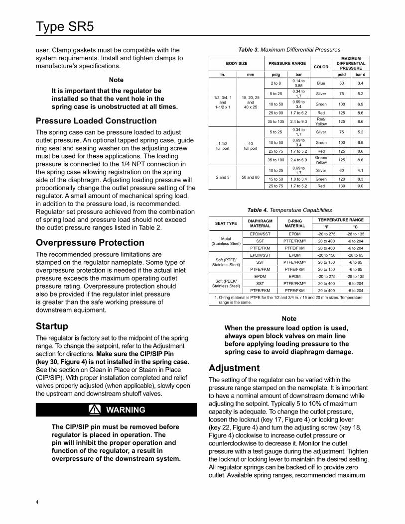
Table 4. Temperature Capabilities
SEaT TyPE DiaPhRagM MaTERiaL
O-RINg MaTERiaL
TEMPERaTURE RangE
°F °C
Metal (Stainless Steel)
EPDM/SST EPDM -20 to 275 -28 to 135
SST PTFE/FKM(1) 20 to 400 -6 to 204
PTFE/FKM PTFE/FKM 20 to 400 -6 to 204
Soft (PTFE/Stainless Steel)
EPDM/SST EPDM -20 to 150 -28 to 65
SST PTFE/FKM(1) 20 to 150 -6 to 65
PTFE/FKM PTFE/FKM 20 to 150 -6 to 65
Soft (PEEK/Stainless Steel)
EPDM EPDM -20 to 275 -28 to 135
SST PTFE/FKM(1) 20 to 400 -6 to 204
PTFE/FKM PTFE/FKM 20 to 400 -6 to 204
1. O-ring material is PTFE for the 1/2 and 3/4 in. / 15 and 20 mm sizes. Temperature range is the same.
Table 3. Maximum Differential Pressures
BODy SizE PRESSURE RangECOLOR
MaXiMUM DiFFEREnTiaL
PRESSUREin. mm psig bar psid bar d
1/2, 3/4, 1 and
1-1/2 x 1
15, 20, 25 and
40 x 25
2 to 8 0.14 to 0.55 Blue 50 3.4
5 to 25 0.34 to 1.7 Silver 75 5.2
10 to 50 0.69 to 3.4 Green 100 6.9
25 to 90 1.7 to 6.2 Red 125 8.6
35 to 135 2.4 to 9.3 Red/Yellow 125 8.6
1-1/2full port
40full port
5 to 25 0.34 to 1.7 Silver 75 5.2
10 to 50 0.69 to 3.4 Green 100 6.9
25 to 75 1.7 to 5.2 Red 125 8.6
35 to 100 2.4 to 6.9 Green/Yellow 125 8.6
2 and 3 50 and 80
10 to 25 0.69 to 1.7 Silver 60 4.1
15 to 50 1.0 to 3.4 Green 120 8.3
25 to 75 1.7 to 5.2 Red 130 9.0
noteWhen the pressure load option is used, always open block valves on main line before applying loading pressure to the spring case to avoid diaphragm damage.
adjustmentThe setting of the regulator can be varied within the pressure range stamped on the nameplate. It is important to have a nominal amount of downstream demand while adjusting the setpoint. Typically 5 to 10% of maximum capacity is adequate. To change the outlet pressure, loosen the locknut (key 17, Figure 4) or locking lever (key 22, Figure 4) and turn the adjusting screw (key 18, Figure 4) clockwise to increase outlet pressure or counterclockwise to decrease it. Monitor the outlet pressure with a test gauge during the adjustment. Tighten the locknut or locking lever to maintain the desired setting. All regulator springs can be backed off to provide zero outlet. Available spring ranges, recommended maximum
Type SR5
5
allowable differential pressures and spring data are shown in Tables 2 and 3.
ShutdownClose the upstream shutoff valve. Close downstream shutoff valve. Open the bleed valve between the regulator and the downstream shutoff valve. Without changing regulator spring adjustment, all pressure between the upstream and downstream shutoff valves is released through the bleed valve, since the regulator opens in response to the decreased outlet pressure.
noteWhen the pressure loaded option is used, bleed all pressure from the spring case before bleeding pressure under the diaphragm to avoid internal part damage.
Clean in Place or Steam in Place (CIP/SIP)To prevent valve plug closing, insert the CIP/SIP pin (key 30, Figure 4) completely so that spring ball in the end of pin is secured into the vent hole on the side of the spring case. Be sure to insert pin when regulator is in the open position.
! WaRning
The CIP/SIP pin must be removed before regulator is placed in operation. The pin will inhibit the proper operation and function of the regulator and result in overpressure of the downstream system.
Maintenance
! WaRning
Before disassembling the regulator, isolate it from the pressure system and release all pressure from the regulator as specified in the Shutdown section. Relieve all spring compression and isolate regulator from the pressurized system prior to removing the clamp (key 15).
Due to normal wear that may occur, parts must be periodically inspected and replaced if necessary. The frequency of inspection depends on the severity of service conditions. A preventative maintenance schedule should be implemented that checks regulator setpoint and lockup and that evaluates
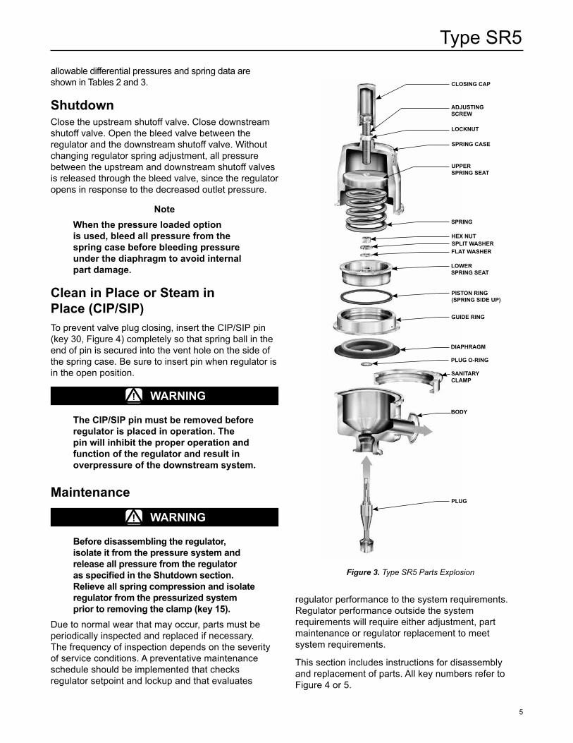
Figure 3. Type SR5 Parts Explosion
CLOSing CaP
aDjUSTing SCREW
LOCknUT
SPRing CaSE
UPPER SPRing SEaT
SPRing
hEX nUTSPLiT WaShERFLaT WaShER
LOWER SPRing SEaT
PiSTOn Ring(SPRing SiDE UP)
gUiDE Ring
DiaPhRagM
PlUg O-RINg
SaniTaRy CLaMP
BODy
PLUg
regulator performance to the system requirements. Regulator performance outside the system requirements will require either adjustment, part maintenance or regulator replacement to meet system requirements.
This section includes instructions for disassembly and replacement of parts. All key numbers refer to Figure 4 or 5.
Type SR5
6
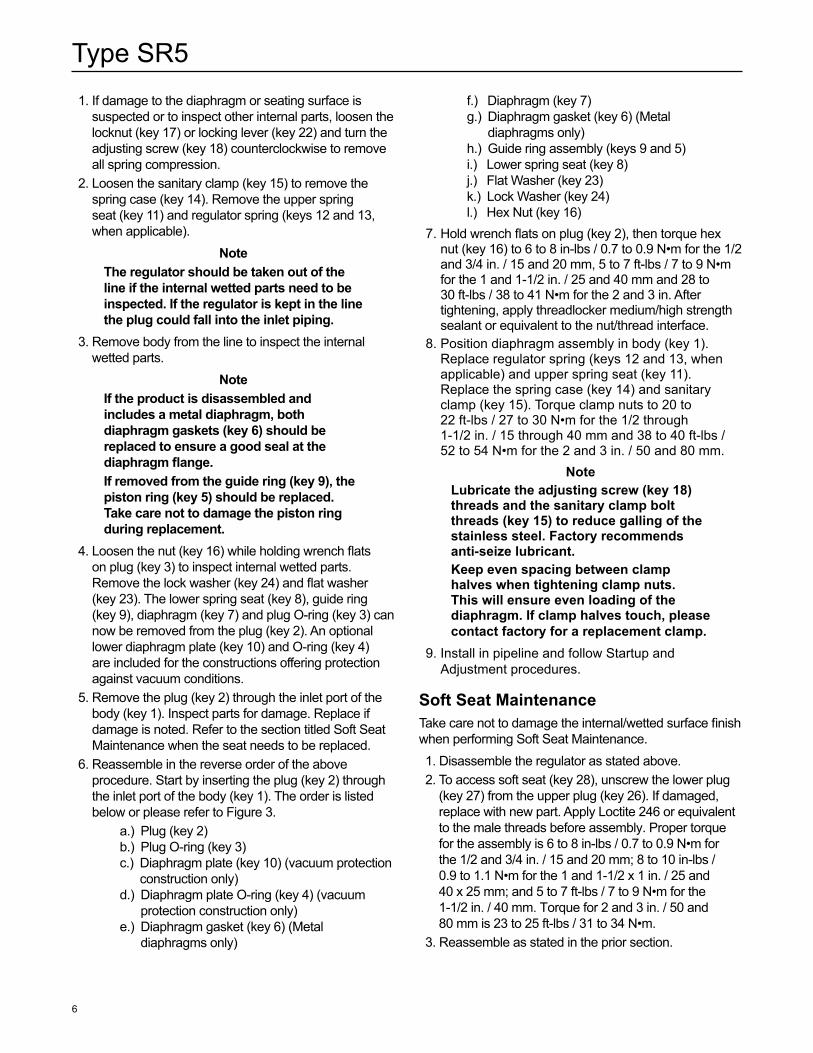
1. If damage to the diaphragm or seating surface is suspected or to inspect other internal parts, loosen the locknut (key 17) or locking lever (key 22) and turn the adjusting screw (key 18) counterclockwise to remove all spring compression.
2. Loosen the sanitary clamp (key 15) to remove the spring case (key 14). Remove the upper spring seat (key 11) and regulator spring (keys 12 and 13, when applicable).
noteThe regulator should be taken out of the line if the internal wetted parts need to be inspected. if the regulator is kept in the line the plug could fall into the inlet piping.
3. Remove body from the line to inspect the internal wetted parts.
noteif the product is disassembled and includes a metal diaphragm, both diaphragm gaskets (key 6) should be replaced to ensure a good seal at the diaphragm flange.if removed from the guide ring (key 9), the piston ring (key 5) should be replaced. Take care not to damage the piston ring during replacement.
4. Loosen the nut (key 16) while holding wrench flats on plug (key 3) to inspect internal wetted parts. Remove the lock washer (key 24) and flat washer (key 23). The lower spring seat (key 8), guide ring (key 9), diaphragm (key 7) and plug O-ring (key 3) can now be removed from the plug (key 2). An optional lower diaphragm plate (key 10) and O-ring (key 4) are included for the constructions offering protection against vacuum conditions.
5. Remove the plug (key 2) through the inlet port of the body (key 1). Inspect parts for damage. Replace if damage is noted. Refer to the section titled Soft Seat Maintenance when the seat needs to be replaced.
6. Reassemble in the reverse order of the above procedure. Start by inserting the plug (key 2) through the inlet port of the body (key 1). The order is listed below or please refer to Figure 3.
a.) Plug (key 2) b.) Plug O-ring (key 3) c.) Diaphragm plate (key 10) (vacuum protection
construction only) d.) Diaphragm plate O-ring (key 4) (vacuum
protection construction only) e.) Diaphragm gasket (key 6) (Metal
diaphragms only)
f.) Diaphragm (key 7) g.) Diaphragm gasket (key 6) (Metal
diaphragms only) h.) Guide ring assembly (keys 9 and 5) i.) Lower spring seat (key 8) j.) Flat Washer (key 23) k.) Lock Washer (key 24) l.) Hex Nut (key 16) 7. Hold wrench flats on plug (key 2), then torque hex
nut (key 16) to 6 to 8 in-lbs / 0.7 to 0.9 N•m for the 1/2 and 3/4 in. / 15 and 20 mm, 5 to 7 ft-lbs / 7 to 9 N•m for the 1 and 1-1/2 in. / 25 and 40 mm and 28 to 30 ft-lbs / 38 to 41 N•m for the 2 and 3 in. After tightening, apply threadlocker medium/high strength sealant or equivalent to the nut/thread interface.
8. Position diaphragm assembly in body (key 1). Replace regulator spring (keys 12 and 13, when applicable) and upper spring seat (key 11). Replace the spring case (key 14) and sanitary clamp (key 15). Torque clamp nuts to 20 to 22 ft-lbs / 27 to 30 N•m for the 1/2 through 1-1/2 in. / 15 through 40 mm and 38 to 40 ft-lbs / 52 to 54 N•m for the 2 and 3 in. / 50 and 80 mm.
notelubricate the adjusting screw (key 18) threads and the sanitary clamp bolt threads (key 15) to reduce galling of the stainless steel. Factory recommends anti-seize lubricant.keep even spacing between clamp halves when tightening clamp nuts. This will ensure even loading of the diaphragm. if clamp halves touch, please contact factory for a replacement clamp.
9. Install in pipeline and follow Startup and Adjustment procedures.
Soft Seat MaintenanceTake care not to damage the internal/wetted surface finish when performing Soft Seat Maintenance. 1. Disassemble the regulator as stated above. 2. To access soft seat (key 28), unscrew the lower plug
(key 27) from the upper plug (key 26). If damaged, replace with new part. Apply Loctite 246 or equivalent to the male threads before assembly. Proper torque for the assembly is 6 to 8 in-lbs / 0.7 to 0.9 N•m for the 1/2 and 3/4 in. / 15 and 20 mm; 8 to 10 in-lbs / 0.9 to 1.1 N•m for the 1 and 1-1/2 x 1 in. / 25 and 40 x 25 mm; and 5 to 7 ft-lbs / 7 to 9 N•m for the 1-1/2 in. / 40 mm. Torque for 2 and 3 in. / 50 and 80 mm is 23 to 25 ft-lbs / 31 to 34 N•m.
3. Reassemble as stated in the prior section.
Type SR5
7
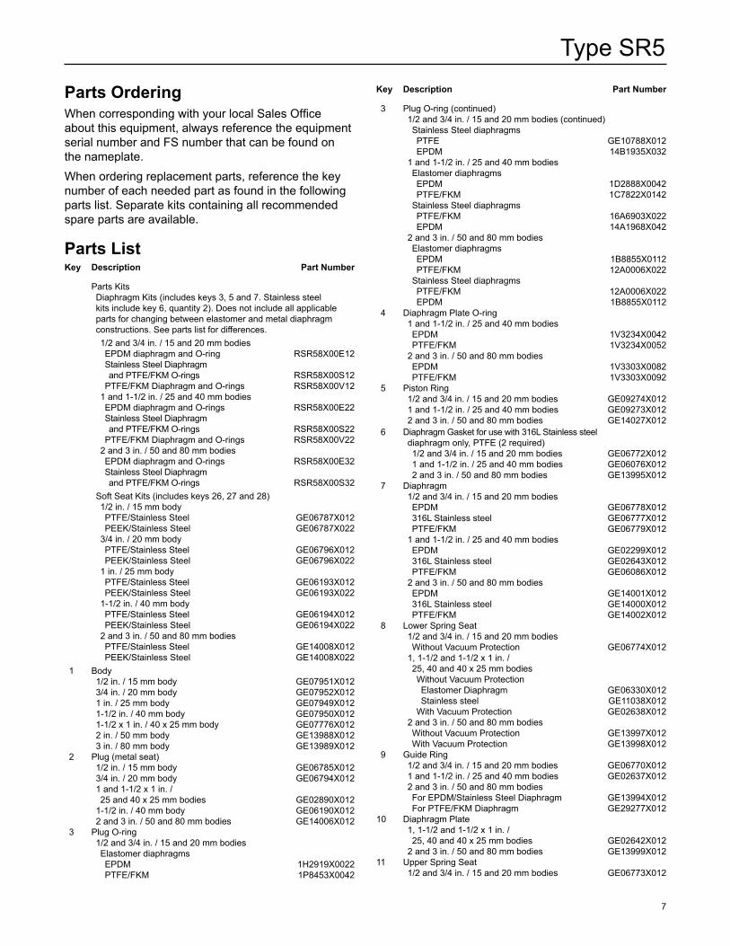
Parts OrderingWhen corresponding with your local Sales Office about this equipment, always reference the equipment serial number and FS number that can be found on the nameplate.When ordering replacement parts, reference the key number of each needed part as found in the following parts list. Separate kits containing all recommended spare parts are available.
Parts Listkey Description Part number
Parts Kits Diaphragm Kits (includes keys 3, 5 and 7. Stainless steel kits include key 6, quantity 2). Does not include all applicable parts for changing between elastomer and metal diaphragm constructions. See parts list for differences. 1/2 and 3/4 in. / 15 and 20 mm bodies EPDM diaphragm and O-ring RSR58X00E12 Stainless Steel Diaphragm and PTFE/FKM O-rings RSR58X00S12 PTFE/FKM Diaphragm and O-rings RSR58X00V12 1 and 1-1/2 in. / 25 and 40 mm bodies EPDM diaphragm and O-rings RSR58X00E22 Stainless Steel Diaphragm and PTFE/FKM O-rings RSR58X00S22 PTFE/FKM Diaphragm and O-rings RSR58X00V22 2 and 3 in. / 50 and 80 mm bodies EPDM diaphragm and O-rings RSR58X00E32 Stainless Steel Diaphragm and PTFE/FKM O-rings RSR58X00S32 Soft Seat Kits (includes keys 26, 27 and 28) 1/2 in. / 15 mm body PTFE/Stainless Steel GE06787X012 PEEK/Stainless Steel GE06787X022 3/4 in. / 20 mm body PTFE/Stainless Steel GE06796X012 PEEK/Stainless Steel GE06796X022 1 in. / 25 mm body PTFE/Stainless Steel GE06193X012 PEEK/Stainless Steel GE06193X022 1-1/2 in. / 40 mm body PTFE/Stainless Steel GE06194X012 PEEK/Stainless Steel GE06194X022 2 and 3 in. / 50 and 80 mm bodies PTFE/Stainless Steel GE14008X012 PEEK/Stainless Steel GE14008X022 1 Body 1/2 in. / 15 mm body GE07951X012 3/4 in. / 20 mm body GE07952X012 1 in. / 25 mm body GE07949X012 1-1/2 in. / 40 mm body GE07950X012 1-1/2 x 1 in. / 40 x 25 mm body GE07776X012 2 in. / 50 mm body GE13988X012 3 in. / 80 mm body GE13989X012 2 Plug (metal seat) 1/2 in. / 15 mm body GE06785X012 3/4 in. / 20 mm body GE06794X012 1 and 1-1/2 x 1 in. / 25 and 40 x 25 mm bodies GE02890X012 1-1/2 in. / 40 mm body GE06190X012 2 and 3 in. / 50 and 80 mm bodies GE14006X012 3 Plug O-ring 1/2 and 3/4 in. / 15 and 20 mm bodies Elastomer diaphragms EPDM 1H2919X0022 PTFE/FKM 1P8453X0042
key Description Part number
3 Plug O-ring (continued) 1/2 and 3/4 in. / 15 and 20 mm bodies (continued) Stainless Steel diaphragms PTFE GE10788X012 EPDM 14B1935X032 1 and 1-1/2 in. / 25 and 40 mm bodies Elastomer diaphragms EPDM 1D2888X0042 PTFE/FKM 1C7822X0142 Stainless Steel diaphragms PTFE/FKM 16A6903X022 EPDM 14A1968X042 2 and 3 in. / 50 and 80 mm bodies Elastomer diaphragms EPDM 1B8855X0112 PTFE/FKM 12A0006X022 Stainless Steel diaphragms PTFE/FKM 12A0006X022 EPDM 1B8855X0112 4 Diaphragm Plate O-ring 1 and 1-1/2 in. / 25 and 40 mm bodies EPDM 1V3234X0042 PTFE/FKM 1V3234X0052 2 and 3 in. / 50 and 80 mm bodies EPDM 1V3303X0082 PTFE/FKM 1V3303X0092 5 Piston Ring 1/2 and 3/4 in. / 15 and 20 mm bodies GE09274X012 1 and 1-1/2 in. / 25 and 40 mm bodies GE09273X012 2 and 3 in. / 50 and 80 mm bodies GE14027X012 6 Diaphragm Gasket for use with 316L Stainless steel diaphragm only, PTFE (2 required) 1/2 and 3/4 in. / 15 and 20 mm bodies GE06772X012 1 and 1-1/2 in. / 25 and 40 mm bodies GE06076X012 2 and 3 in. / 50 and 80 mm bodies GE13995X012 7 Diaphragm 1/2 and 3/4 in. / 15 and 20 mm bodies EPDM GE06778X012 316L Stainless steel GE06777X012 PTFE/FKM GE06779X012 1 and 1-1/2 in. / 25 and 40 mm bodies EPDM GE02299X012 316L Stainless steel GE02643X012 PTFE/FKM GE06086X012 2 and 3 in. / 50 and 80 mm bodies EPDM GE14001X012 316L Stainless steel GE14000X012 PTFE/FKM GE14002X012 8 Lower Spring Seat 1/2 and 3/4 in. / 15 and 20 mm bodies Without Vacuum Protection GE06774X012 1, 1-1/2 and 1-1/2 x 1 in. / 25, 40 and 40 x 25 mm bodies Without Vacuum Protection Elastomer Diaphragm GE06330X012 Stainless steel GE11038X012 With Vacuum Protection GE02638X012 2 and 3 in. / 50 and 80 mm bodies Without Vacuum Protection GE13997X012 With Vacuum Protection GE13998X012 9 Guide Ring 1/2 and 3/4 in. / 15 and 20 mm bodies GE06770X012 1 and 1-1/2 in. / 25 and 40 mm bodies GE02637X012 2 and 3 in. / 50 and 80 mm bodies For EPDM/Stainless Steel Diaphragm GE13994X012 For PTFE/FKM Diaphragm GE29277X01210 Diaphragm Plate 1, 1-1/2 and 1-1/2 x 1 in. / 25, 40 and 40 x 25 mm bodies GE02642X012 2 and 3 in. / 50 and 80 mm bodies GE13999X01211 Upper Spring Seat 1/2 and 3/4 in. / 15 and 20 mm bodies GE06773X012

Type SR5
8
Figure 4. Type SR5 Sanitary Regulator Assembly1/2 through 1-1/2 In. / 15 through 40 mm Sizes
SOFT SEaT OPTiOn
ViEW B – METaL DiaPhRagM FOR STanDaRD REgULaTOR
VaCUUM PROTECTiOn OPTiOnGE02640
aa
APPlY lUBRICANT (l) / SEAlANT (S)(1):l = ANTI-SEIzE lUBRICANTS1 = ThREAdlOCkER MEdIUM/hIgh STRENgTh SEAlANTS2 = hIgh TEMPERATURE ANd MEdIUM STRENgTh ThREAdlOCkER SEAlANT1. Lubricant and sealant must be selected such that they meet the temperature requirements.
ViEW aROTATEd 180°
T-hANdlE OPTION
STanDaRD REgULaTOR WiTh ELaSTOMERiC DiaPhRagM
11
19
18
17
16
24
23
8
9
7
3
2
1
5
15
12
14
31
30
B
13
1514
9
6
61
7
26
28
27
18
22
21
20
29
29
8
9
437 10
LS1
S2
L
Type SR5
9
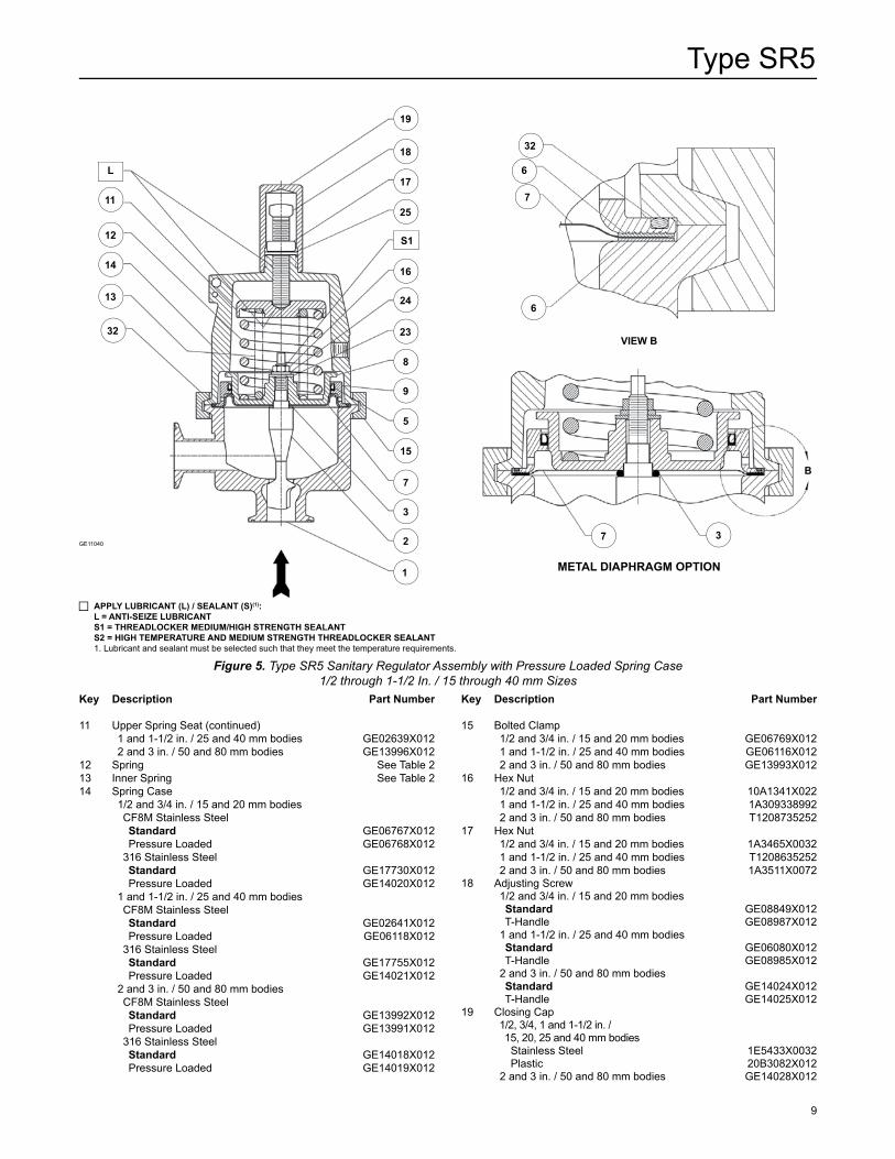
Figure 5. Type SR5 Sanitary Regulator Assembly with Pressure Loaded Spring Case1/2 through 1-1/2 In. / 15 through 40 mm Sizes
ViEW B
GE11040
METaL DiaPhRagM OPTiOn
11
12
14
13
32
19
18
17
25
16
24
23
8
9
5
15
7
3
2
1
7
6
6
32
7 3
B
key Description Part number
11 Upper Spring Seat (continued) 1 and 1-1/2 in. / 25 and 40 mm bodies GE02639X012 2 and 3 in. / 50 and 80 mm bodies GE13996X01212 Spring See Table 213 Inner Spring See Table 214 Spring Case 1/2 and 3/4 in. / 15 and 20 mm bodies CF8M Stainless Steel
Standard GE06767X012 Pressure Loaded GE06768X012 316 Stainless Steel
Standard GE17730X012 Pressure Loaded GE14020X012 1 and 1-1/2 in. / 25 and 40 mm bodies CF8M Stainless Steel
Standard GE02641X012 Pressure Loaded GE06118X012 316 Stainless Steel
Standard GE17755X012 Pressure Loaded GE14021X012 2 and 3 in. / 50 and 80 mm bodies CF8M Stainless Steel
Standard GE13992X012 Pressure Loaded GE13991X012 316 Stainless Steel
Standard GE14018X012 Pressure Loaded GE14019X012
key Description Part number
15 Bolted Clamp 1/2 and 3/4 in. / 15 and 20 mm bodies GE06769X012 1 and 1-1/2 in. / 25 and 40 mm bodies GE06116X012 2 and 3 in. / 50 and 80 mm bodies GE13993X01216 Hex Nut 1/2 and 3/4 in. / 15 and 20 mm bodies 10A1341X022 1 and 1-1/2 in. / 25 and 40 mm bodies 1A309338992 2 and 3 in. / 50 and 80 mm bodies T120873525217 Hex Nut 1/2 and 3/4 in. / 15 and 20 mm bodies 1A3465X0032 1 and 1-1/2 in. / 25 and 40 mm bodies T1208635252 2 and 3 in. / 50 and 80 mm bodies 1A3511X007218 Adjusting Screw 1/2 and 3/4 in. / 15 and 20 mm bodies
Standard GE08849X012 T-Handle GE08987X012 1 and 1-1/2 in. / 25 and 40 mm bodies
Standard GE06080X012 T-Handle GE08985X012 2 and 3 in. / 50 and 80 mm bodies
Standard GE14024X012 T-Handle GE14025X01219 Closing Cap 1/2, 3/4, 1 and 1-1/2 in. / 15, 20, 25 and 40 mm bodies Stainless Steel 1E5433X0032 Plastic 20B3082X012 2 and 3 in. / 50 and 80 mm bodies GE14028X012
L
S1
APPlY lUBRICANT (l) / SEAlANT (S)(1):l = ANTI-SEIzE lUBRICANTS1 = ThREAdlOCkER MEdIUM/hIgh STRENgTh SEAlANTS2 = hIgh TEMPERATURE ANd MEdIUM STRENgTh ThREAdlOCkER SEAlANT1. Lubricant and sealant must be selected such that they meet the temperature requirements.
Type SR5
10
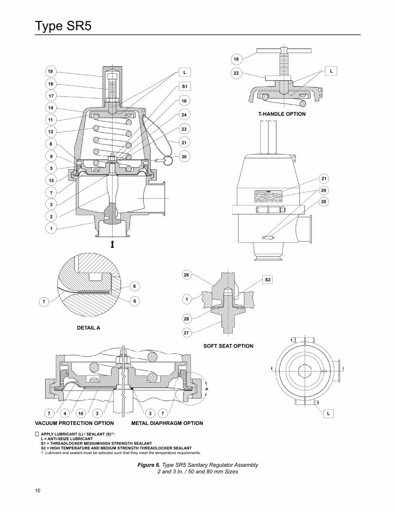
DETaiL a
SOFT SEaT OPTiOn
T-hANdlE OPTION
VaCUUM PROTECTiOn OPTiOn METaL DiaPhRagM OPTiOn
Figure 6. Type SR5 Sanitary Regulator Assembly2 and 3 In. / 50 and 80 mm Sizes
16
24
23
31
30
19
18
17
14
11
12
8
9
5
15
7
3
2
1
18
22
21
29
20
26
1
28
27
7 4 10 3 3 7
7
6
6
a
L
L
L
S1
S2
APPlY lUBRICANT (l) / SEAlANT (S)(1):l = ANTI-SEIzE lUBRICANTS1 = ThREAdlOCkER MEdIUM/hIgh STRENgTh SEAlANTS2 = hIgh TEMPERATURE ANd MEdIUM STRENgTh ThREAdlOCkER SEAlANT1. Lubricant and sealant must be selected such that they meet the temperature requirements.
Type SR5
11
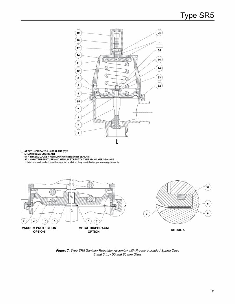
DETaiL a VaCUUM PROTECTiOn OPTiOn
METaL DiaPhRagM OPTiOn
Figure 7. Type SR5 Sanitary Regulator Assembly with Pressure Loaded Spring Case2 and 3 In. / 50 and 80 mm Sizes
19
18
17
14
11
12
8
9
5
15
7
3
2
1
25
16
24
23
32
7
6
6
32
7 4 10 3 3 7
a
L
S1
APPlY lUBRICANT (l) / SEAlANT (S)(1):l = ANTI-SEIzE lUBRICANTS1 = ThREAdlOCkER MEdIUM/hIgh STRENgTh SEAlANTS2 = hIgh TEMPERATURE ANd MEdIUM STRENgTh ThREAdlOCkER SEAlANT1. Lubricant and sealant must be selected such that they meet the temperature requirements.
Type SR5
©Emerson Process Management Regulator Technologies, Inc., 2006, 2015; All Rights Reserved
The Emerson logo is a trademark and service mark of Emerson Electric Co. All other marks are the property of their prospective owners. Fisher is a mark owned by Fisher Controls International LLC, a business of Emerson Process Management.
The contents of this publication are presented for informational purposes only, and while every effort has been made to ensure their accuracy, they are not to be construed as warranties or guarantees, express or implied, regarding the products or services described herein or their use or applicability. We reserve the right to modify or improve the designs or specifications of such products at any time without notice.
Emerson Process Management Regulator Technologies, Inc. does not assume responsibility for the selection, use or maintenance of any product. Responsibility for proper selection, use and maintenance of any Emerson Process Management Regulator Technologies, Inc. product remains solely with the purchaser.
Industrial Regulators
Emerson Process Management Regulator Technologies, Inc.
USA - HeadquartersMcKinney, Texas 75070 USATel: +1 800 558 5853Outside U.S. +1 972 548 3574
Asia-PacificShanghai 201206, ChinaTel: +86 21 2892 9000
EuropeBologna 40013, ItalyTel: +39 051 419 0611
Middle East and AfricaDubai, United Arab EmiratesTel: +971 4811 8100
Natural Gas Technologies
Emerson Process ManagementRegulator Technologies, Inc.
USA - HeadquartersMcKinney, Texas 75070 USATel: +1 800 558 5853Outside U.S. +1 972 548 3574
Asia-PacificSingapore 128461, SingaporeTel: +65 6770 8337
EuropeBologna 40013, ItalyTel: +39 051 419 0611Chartres 28008, FranceTel: +33 2 37 33 47 00
Middle East and AfricaDubai, United Arab EmiratesTel: +971 4811 8100
TESCOM
Emerson Process ManagementTescom Corporation
USA - HeadquartersElk River, Minnesota 55330-2445, USATels: +1 763 241 3238 +1 800 447 1250
EuropeSelmsdorf 23923, GermanyTel: +49 38823 31 287
Asia-PacificShanghai 201206, ChinaTel: +86 21 2892 9499
For further information visit www.fisherregulators.com
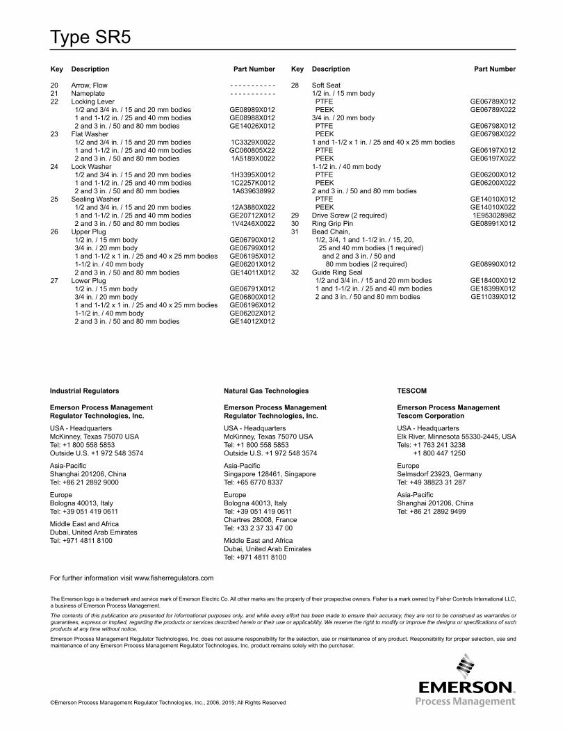
key Description Part number
20 Arrow, Flow - - - - - - - - - - -21 Nameplate - - - - - - - - - - - 22 Locking Lever 1/2 and 3/4 in. / 15 and 20 mm bodies GE08989X012 1 and 1-1/2 in. / 25 and 40 mm bodies GE08988X012 2 and 3 in. / 50 and 80 mm bodies GE14026X01223 Flat Washer 1/2 and 3/4 in. / 15 and 20 mm bodies 1C3329X0022 1 and 1-1/2 in. / 25 and 40 mm bodies GC060805X22 2 and 3 in. / 50 and 80 mm bodies 1A5189X002224 Lock Washer 1/2 and 3/4 in. / 15 and 20 mm bodies 1H3395X0012 1 and 1-1/2 in. / 25 and 40 mm bodies 1C2257K0012 2 and 3 in. / 50 and 80 mm bodies 1A63963899225 Sealing Washer 1/2 and 3/4 in. / 15 and 20 mm bodies 12A3880X022 1 and 1-1/2 in. / 25 and 40 mm bodies GE20712X012 2 and 3 in. / 50 and 80 mm bodies 1V4246X002226 Upper Plug 1/2 in. / 15 mm body GE06790X012 3/4 in. / 20 mm body GE06799X012 1 and 1-1/2 x 1 in. / 25 and 40 x 25 mm bodies GE06195X012 1-1/2 in. / 40 mm body GE06201X012 2 and 3 in. / 50 and 80 mm bodies GE14011X01227 Lower Plug 1/2 in. / 15 mm body GE06791X012 3/4 in. / 20 mm body GE06800X012 1 and 1-1/2 x 1 in. / 25 and 40 x 25 mm bodies GE06196X012 1-1/2 in. / 40 mm body GE06202X012 2 and 3 in. / 50 and 80 mm bodies GE14012X012
key Description Part number
28 Soft Seat 1/2 in. / 15 mm body PTFE GE06789X012 PEEK GE06789X022 3/4 in. / 20 mm body PTFE GE06798X012 PEEK GE06798X022 1 and 1-1/2 x 1 in. / 25 and 40 x 25 mm bodies PTFE GE06197X012 PEEK GE06197X022 1-1/2 in. / 40 mm body PTFE GE06200X012 PEEK GE06200X022 2 and 3 in. / 50 and 80 mm bodies PTFE GE14010X012 PEEK GE14010X02229 Drive Screw (2 required) 1E95302898230 Ring Grip Pin GE08991X01231 Bead Chain, 1/2, 3/4, 1 and 1-1/2 in. / 15, 20, 25 and 40 mm bodies (1 required) and 2 and 3 in. / 50 and 80 mm bodies (2 required) GE08990X01232 Guide Ring Seal 1/2 and 3/4 in. / 15 and 20 mm bodies GE18400X012 1 and 1-1/2 in. / 25 and 40 mm bodies GE18399X012 2 and 3 in. / 50 and 80 mm bodies GE11039X012