Separation of carbon 13 by thermal diffusion
42
SEPARATION OF CARBON-13 BY THERMAL DIFFUSION GHEORGHE VASARU Aleea Tarnita, Nr. 7, Apt. 11 400649 CLUJ-NAPOCA, ROMANIA E-mail: [email protected]
-
Upload
gheorghe-vasaru -
Category
Engineering
-
view
62 -
download
5
Transcript of Separation of carbon 13 by thermal diffusion
SEPARATION OF CARBON-13 BY THERMAL
DIFFUSION
GHEORGHE VASARUAleea Tarnita, Nr. 7, Apt. 11
400649 CLUJ-NAPOCA, ROMANIAE-mail: [email protected]

ABSTRACT
In the selection of a process gas for use in the separation of 13C by thermal diffusion, methane is a first candidate because of its low molecular weight. Generally, the process equipment to be employed for this separation consists of concentric tube columns with calrod heaters, which are normally operated at a mean temperature no more than 673 K because methane decomposes at greater temperatures.
This paper gives a short overview of the most important applications of 13C and describes a thermal diffusion cascade for enrichment of this isotope.
Successively, the results of calculations of the transport coefficients H and K for a concentric tube column, operated with methane as process gas, are presented. Static separation factor at equilibrium vs gas pressure has been calculated for various molecular models. The experimental separation factors for different gas pressures were found to be consistent with those calculated for the inverse power repulsion model and the Lennard-Jones (12,6) model.
Thermal Diffusion Process
The thermal diffusion process is based on the fact that molecular diffusion can be caused by a temperature gradient. In general, if two gases are exposed to a temperature gradient between two surfaces, the gas with the lower molecular weight will tend toward the hotter surface. The two gases will separate until a concentration gradient occurs resulting in concentration diffusion of equal magnitude in the opposite direction. Under equilibrium conditions the rate of transfer of the light molecules towards the hot surface resulting from thermal diffusion will be exactly counterbalanced by concentration diffusion.
In a thermal diffusion column the relatively small separation factor is multiplied by the effect of convection currents resulting from the temperature gradient. The heavy molecules, which tend toward the cold surface, are swept to the bottom of the column while the light molecules at the hot surface are swept toward the top of the column. The maximum separation is limited by the concentration diffusion that is eventually set up in the axial direction as a result of the separation itself.

Thermal Diffusion Process (Cont’d)
This transport phenomena makes available enriched isotopes which either cannot be provided by other separation methods or are more costly when prepared by alternate means with emphasis on concentrating isotopes of the inert gases. The heaviest and lightest isotopes in such mixtures can easily be enriched to any desired concentration if a proper thermal diffusion cascade is constructed 1- 4. A cascade to enrich an isotope of other than the greatest or least mass in a mixture of three or more components become more complicated in arrangement and offers design problems relative to length, width and flow rates.
Construction of thermal diffusion column presents engineering problems associated with supported heated central elements. At the present time, thermal diffusion columns are designed to use standard, commercial tubular heaters or wire heaters with an effective length of some meters. To conserve space, 12 to 19 columns are enclosed in a common water jacket. Thus, individual columns can be interconnected externally to give any desired shape of cascade. Within the same bundle, some columns can be used for enriching one isotope, while at the same time other columns are being used to enrich a different isotope.

The Transport Equation
The transport equation for a thermal diffusion column is:
dz
dcKKcHc dc )()1( (1)
where is the total transport of required isotope, H is the coefficient of transport by thermal diffusion, c is the fractional molar concentration of the required isotope, Kc is the coefficient of transport by convection currents, Kd is the coefficient of transport by ordinary diffusion, and z is the axial coordinate of the column. Kc and Kd are named also as convective and diffusive remixing coefficients, respectively. According to the Jones and Furry theory 5, H and Kd are functions of pressure; thus
H H p
K K pc c
'
'
2
4 (2)
Kd is independent of pressure.
The Transport Coefficients for Cylindrical Case
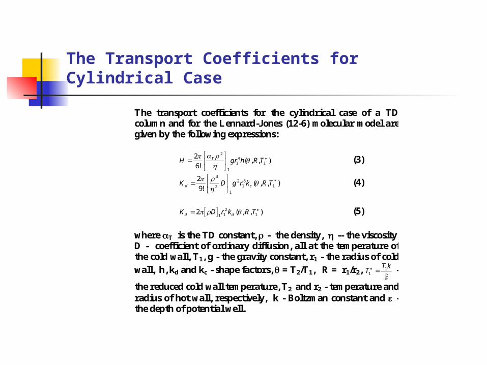
The transport coefficients for the cylindrical case of a TD column and for the Lennard-Jones (12-6) molecular model are given by the following expressions:
),,(!6
21
41
1
2
TRhgrH T
(3)
),,(!9
2 *1
81
2
1
2
3
TRkrgDK cd
(4)
K D r k R Td d 2
1 12
1 ( , , ) (5)
where T is the TD constant, - the density, -- the viscosity, D - coefficient of ordinary diffusion, all at the temperature of the cold wall, T1, g - the gravity constant, r1 - the radius of cold
wall, h, kd and kc - shape factors, = T2/T1, R = r1/r2, TT k
11
-
the reduced cold wall temperature, T2 and r2 - temperature and radius of hot wall, respectively, k - Boltzman constant and - the depth of potential well.

Equilibrium Separation Factor
Putting in (1), = 0, we have
dc
c c
H
K Kdz Adz
c d( )12
(6)
the integral of which is
c
cA z z
12 0
exp (7)
or equivalently
c z A z z( ) tanh ( ) 1
21 0 (8)
If z0 z L and c0 c cL, where L is the length of the thermal diffusion column, we have for the equilibrium separation factor the expression
Qc c
c cALe
L
L
( )
( )exp( )
1
120
0
(9)

The Separation Factor per Mass Unit
The separation factor per mass unit, Q*, is given by the equation:
ln*
QH L
K K Kc d p
(10)
where H* = coefficient of thermal diffusion transport per unit mass, Kc = coefficient of convective remixing, Kd = coefficient of diffusive remixing, Kp = coefficient of parasitic convection L = length of column The coefficient of parasitic remixing, Kp, arises due to unknown inaccuracies within the column such as nonuniform surface temperature distribution and imperfect centering of the heater.

Transport Coefficients vs Pressure
The H*, Kc and Kd factors can be written as function of pressure and take the form
H ap
K bp
K cc
d
*
2
4 (11)
where a, b, and c are constants determined by column geometry and temperature and by properties of the gas. The ratio b/a and c/a can be determined from the equilibrium data, but a different kind of experiment must be performed to estimate a and allow calculation of b and c. These ratios may be computed from the equations [6]:
b
a
L
p Q
c
a
Lp
Q
2
2
2
2
log
log
*
*
(12)
where p = gas pressure at which the maximum separation factor occurs, Q* = separation factor per unit mass at the maximum in the curve. Pressure at the maximum separation.
When the gas pressure in a thermal diffusion column is adjusted to achieve maximum separation, the coefficient of convective remixing, Kc, is equal to the coefficient of diffusive remixing, Kd,


Heat Losses
Heat is removed in four ways from the heating element in a thermal diffusion column: by radiation from the heater, by convection currents in the gas, by conduction through the gas, and by conduction through the spacers between the heater and the cold wall and lengthwise through the heater sheets to the cold jacket end fittings [7].
Convection and conduction through the gas are essential for the operation of a thermal diffusion column, but if the heat loss via radiation or direct conduction through the spacers can be decreased, the over-all economy of operation will increase. Theoretical and experimental investigations of heater temperature and various modes of heat transfer to the cold wall were undertaken to better understand column operation and to increase the efficiency and economy of isotope separation by thermal diffusion.
The amount of heat radiated from the heater and the amount conducted through the spacers and sheets can be determined from power input and heater sheath temperature with an evacuated column.

Tapered Cascade
If an efficient tapered cascade is to be designed to enrich an isotope from some small concentration to some higher concentrations, the thermal diffusion characteristics of a given column system must be determined. These characteristics can be computed theoretically. To test the validity of this theory, a series of experiments was performed to determine the agreement between observed values of thermal diffusion separation factors and the theoretical values calculated according to Jones and Furry theory.
The theoretical and observed separation factors for 13CH4, as function of gas pressure show that the maximum equilibrium separation factor occurs at a lower pressure.

Comparison of Separation Methods
Research needs for 13C include nuclear bombardment studies, tracer studies on chemical reaction and biological processes and clinical medicine studies.
Most molecules of biological interest are large and complex. Synthesis with 13C requires several reactions each having a relatively low yield. Consequently, the several grams of 13C would be required to synthesize 1 g of a carbon biological molecule. Thus, if 13C is to be a practical tool in biological research, it must be available in larger quantities at a lower cost.
For producing large quantities of enriched carbon-13 from natural abundance carbon (1.1 % 13C and 98.9 % 12C), R.A.Schwind [8] performed an economic evaluation of four methods: thermal diffusion, distillation, gaseous diffusion and chemical exchange. These processes were chosen because they are only ones for which enough laboratory and production knowledge is available to design large production facilities. From this study, the relative production cost per gram of 13C of a mixture containing 60 % 13C was obtained as a function of the production rate for each of these methods. The cost figures were based on an amortization of the capital equipment cost over a period of 10 years.

Practical Conclusions
The practical conclusions are as follows: Thermal diffusion was found to be most economical method for the production rates below 100 g/a; CO distillation should be used for production rates above 200 g/a. The gaseous diffusion and the CO
The world’s largest unit for 13C production is located in Xenia, Ohio, at Cambridge Isotope Laboratories Inc [9] This plant has been in continuous operation since 1990 producing 99 % 13C at a rate of 30 kg/a. After the current expansion in 1997, the plant capacity has been increased to 120 kg/a. The recent increased interest in this unique isotopic material follows regulatory approval of the first diagnostic test which uses 13C. Recently, the FDA gave approval for clinical use of the 13C Urea Breath Test for the detection of the ulcer-causing bacterium Helicobacter pylori. This new breath test is safer, simpler, and more accurate than other tests which diagnose Helicobacter pylori infection. In this breath test, the patient drinks a solution of non-radioactive 13C Urea and then breathes into a collection device. The test takes only thirty minutes; can be performed in a doctor’s office; avoids the need for stomach endoscope with biopsy an is more accurate than blood tests.

Separation of 13C by Thermal Diffusion Practical Aspects (I)
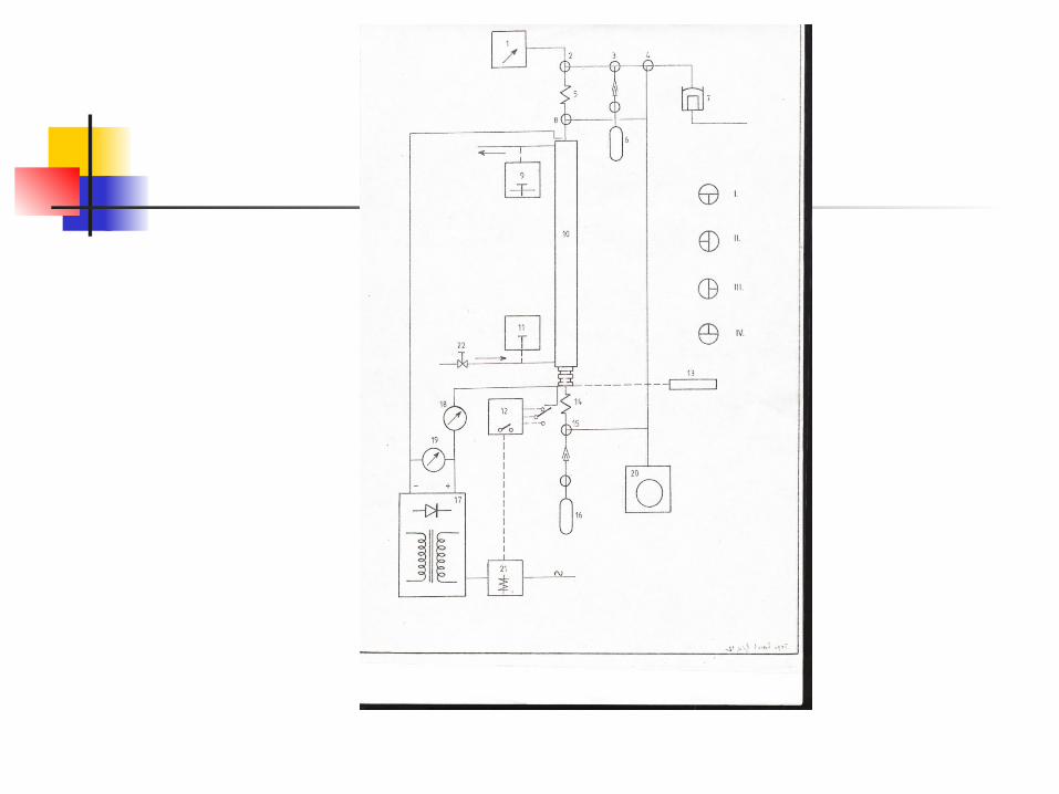
A thermal diffusion cascade has the advantage of being relatively easy to operate. However, thermal diffusion is an irreversible process and therefore require a large quantity of energy per gram of material separated. There is also the disadvantage that the basic thermal diffusion column cannot be scaled up. The gap between the hot and cold walls cannot be increased because the separation factor is proportional to the temperature gradient and there is a practical limit to the obtainable temperature difference. The diameter of thermal diffusion columns cannot be increased above a certain limit because temperature in homogeneities in the hot and cold walls cannot be avoided. For these reasons even a very large-scale thermal diffusion plant must be composed of relatively small diameter thermal columns. A simplified scheme of our standard thermal diffusion column are given in Fig. 1.
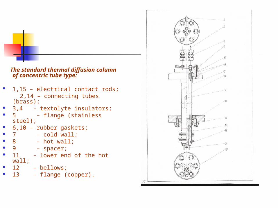
The standard thermal diffusion column of concentric tube type:
1,15 – electrical contact rods; 2,14 – connecting tubes (brass); 3,4 – textolyte insulators; 5 – flange (stainless steel); 6,10 – rubber gaskets; 7 – cold wall; 8 – hot wall; 9 – spacer; 11 – lower end of the hot wall; 12 – bellows; 13 - flange (copper).


Separation of 13C by Thermal Diffusion Practical Aspects (II)
At low production rates, the cost of labor is the controlling factor and the thermal diffusion is an attractive process.
One of the most persistent problems encountered in the 13C thermal diffusion cascade is decomposition of the process gas (methane) into free hydrogen and carbon. Since this decomposition could be catalyzed by the surface of central heater, a series of experiments was conducted to evaluate methane decomposition on various metal surfaces Using a heater made by swaging a soft aluminum sheath over the standard stainless steel calrod, no perceptible decomposition of methane was observed at 673 K.
The performances of several methane thermal diffusion cascades for 13C enrichment from natural abundance was calculated. To guide current laboratory operations, various arrangement of the existing 19-column cascade were evaluated. From the six alternatives we have selected the cascade arrangement of 8-4-2-1-1-1-1-1 columns per stage from feed to product withdrawal, respectively, Fig. 2 10. This cascade was set up with an appropriate system for feed purification, pressure control, waste and product withdrawal, impurity control and removal, and stages gas circulation. In the feed system, methane of 97.4% purity was further purified by pumping volatile impurities, at liquid nitrogen temperature, up to 99.85 - 99.88%. After purification, the methane was stored in a high-pressure bottle from which it was fed through a special system into the feed reservoir. Waste, i.e. depleted methane in 13C was withdrawn from the feed reservoir and stored as methane of high purity.
Enriched methane in 13C was removed continuously from the bottom of the seven stages and stored in a calibrated reservoir.

Separation of 13C by Thermal Diffusion Practical Aspects (III)
The methane used as feed gas was not completely free of impurities such as nitrogen, carbon dioxide and ethane. These impurities introduced with the feed material in cascade are transported at a high rate towards the bottom of the cascade where they accumulate. If these are not removed continuously, the fairly sharp interface between methane and impurities rises rapidly and the effectiveness of the separation system is destroyed 11. For removing these impurities a single column was provided, column 19, placed at the bottom of the cascade. The level of impurities was detected with a thermal-conductivity cell placed at the bottom of the column 19. For reference the enriched methane from the bottom of the seven stage was used. The signal of these sensors was a direct measure of the methane purity in the column. Impurities were withdrawn from the bottom of column 19 through a calibrated leak.
For interstage gas circulation, hermetically sealed compressors was used. Allowing only one column at a moment, in each stage, to be open to the compressor-driven loop obviated the parasitic gas circulation. The columns in stages 1 - 3 were alternately opened to the circulation manifold by solenoid valves operated by an electronic programmer.
The control of enriching during the transient period has been performed by mass spectrometry.
The cascade was operated at the temperature of 673 K, all 19 thermal diffusion column having a single cooling jacket in a bundle system, maintained at the temperature of 293 K. The operating pressure was of 1.05 at.


Parameters of the Methane Thermal Diffusion Cascade
Physical Properties of Methane (at T1 = 295 K):
Density, (g/cm3) 6.626x10⁻⁴
Viscosity, (g/cm.s) 1.110x10⁻⁴
Diffusivity, D (cm2/s) 0.215 Thermal diffusion constant, T 0.00678 Carbon Isotopes: 12C (98.892%); 13C (1.108%) Target: The enrichment of 13C at the concentration of 25% 13CH4 Geometric Parameters and Operating Conditions: Radius of cold wall, r1 (cm) 1.725 Radius of hot wall, r2 (cm) 0.900 Column length, (cm) 400 Temperature of the cold wall, T1 (K) 295 Temperature of the hot wire, T2 (K) 673 Operating pressure, p (at) 1.04 Power consumption per column (kW) 1.7 Materials: hot wall: stainless steel; cold wall: brass Transport Coefficients (LJ model): H (g/s) 4.50x10⁻⁵
Kc (g.cm/s) 2.40x10⁻² Kd (g.cm/s) 1.37x10⁻³
Qe (exp.) per column 2.00 Cascade: 19 columns of concentric tube type in 8 stages Cascade Configuration (Staging from the waste end): 8-4-2-1-1-1-1-1 Production: 13CH4 at the concentration of 25% 13C (g 13C/year): 33
Thank you!


Covers of some publications of the author.
Stable Isotopes


Separation of Isotopes by Thermal Diffusion


Zirconium and his implications in nuclear energy


Ecology Dictionary
Nuclear Geochronology