Sensors and Actuators เซนเซอร์และตัวขับเร้า
34
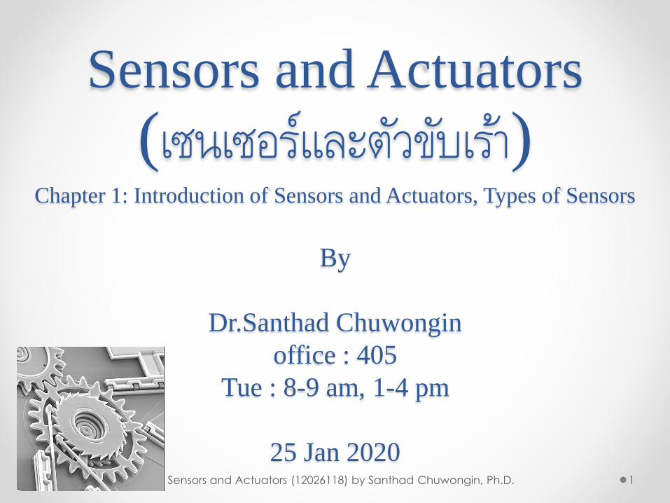
Sensors and Actuators ( เซนเซอร์และตัวขับเร้า ) Chapter 1 : Introduction of Sensors and Actuators, Types of Sensors By Dr.Santhad Chuwongin office : 405 Tue : 8 - 9 am, 1 - 4 pm 25 Jan 2020 1 Sensors and Actuators (12026118) by Santhad Chuwongin, Ph.D.
Transcript of Sensors and Actuators เซนเซอร์และตัวขับเร้า
Sensors and Actuators
(เซนเซอรแ์ละตวัขบัเรา้)Chapter 1: Introduction of Sensors and Actuators, Types of Sensors
By
Dr.Santhad Chuwongin
office : 405
Tue : 8-9 am, 1-4 pm
25 Jan 20201Sensors and Actuators (12026118) by Santhad Chuwongin, Ph.D.
INTRODUCTION OF SENSORS&ACTUATORS
2Sensors and Actuators (12026118) by Santhad Chuwongin, Ph.D.
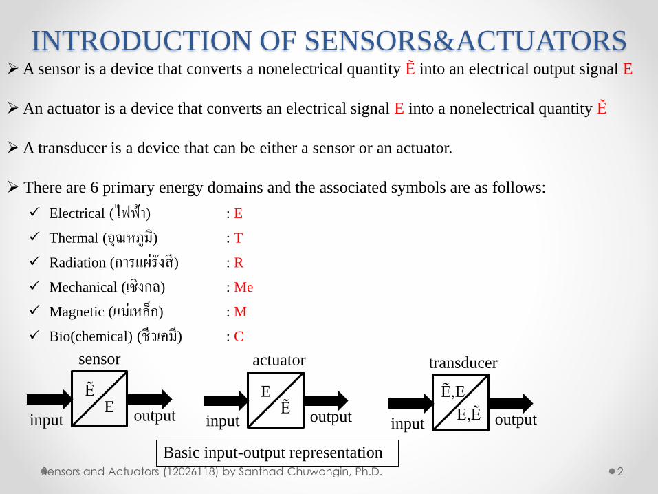
➢A sensor is a device that converts a nonelectrical quantity Ẽ into an electrical output signal E
➢An actuator is a device that converts an electrical signal E into a nonelectrical quantity Ẽ
➢A transducer is a device that can be either a sensor or an actuator.
➢ There are 6 primary energy domains and the associated symbols are as follows:
✓ Electrical (ไฟฟ้า) : E
✓ Thermal (อุณหภูมิ) : T
✓ Radiation (การแผรั่งสี) : R
✓ Mechanical (เชิงกล) : Me
✓ Magnetic (แม่เหลก็) : M
✓ Bio(chemical) (ชีวเคมี) : C
input output
sensor
ẼE
input output
actuator
EẼ
input output
transducer
Ẽ,E
E,Ẽ
Basic input-output representation
INTRODUCTION OF SENSORS&ACTUATORS
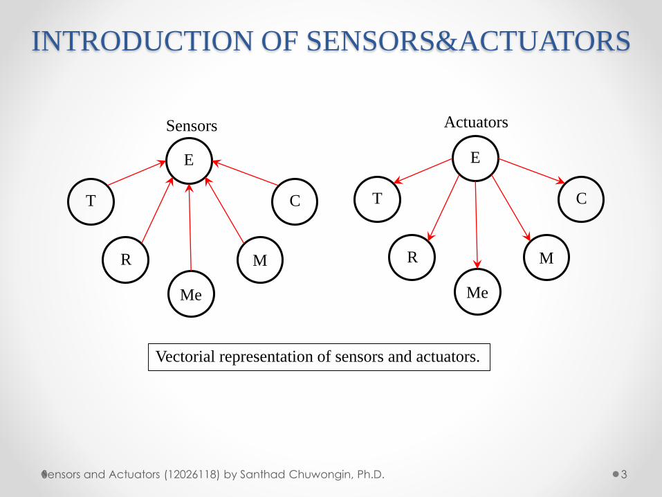
3Sensors and Actuators (12026118) by Santhad Chuwongin, Ph.D.
E
T
R
Me
M
C
Sensors
E
T
R
Me
M
C
Actuators
Vectorial representation of sensors and actuators.
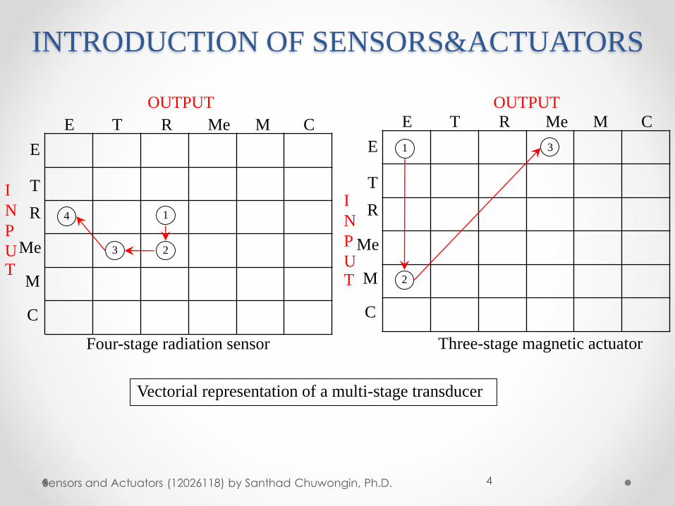
INTRODUCTION OF SENSORS&ACTUATORS
4Sensors and Actuators (12026118) by Santhad Chuwongin, Ph.D.
Vectorial representation of a multi-stage transducer
E T R Me M C
E
T
R
Me
M
C
1
23
4
E T R Me M C
E
T
R
Me
M
C
3
2
Four-stage radiation sensor Three-stage magnetic actuator
OUTPUT
I
N
P
UT
OUTPUT
I
N
P
UT
1
INTRODUCTION OF SENSORS&ACTUATORS
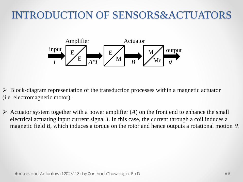
5Sensors and Actuators (12026118) by Santhad Chuwongin, Ph.D.
➢ Block-diagram representation of the transduction processes within a magnetic actuator
(i.e. electromagnetic motor).
➢ Actuator system together with a power amplifier (A) on the front end to enhance the small
electrical actuating input current signal I. In this case, the current through a coil induces a magnetic field B, which induces a torque on the rotor and hence outputs a rotational motion .
input
A*I
Amplifier
EE
B
Actuator
EM
outputM
MeI
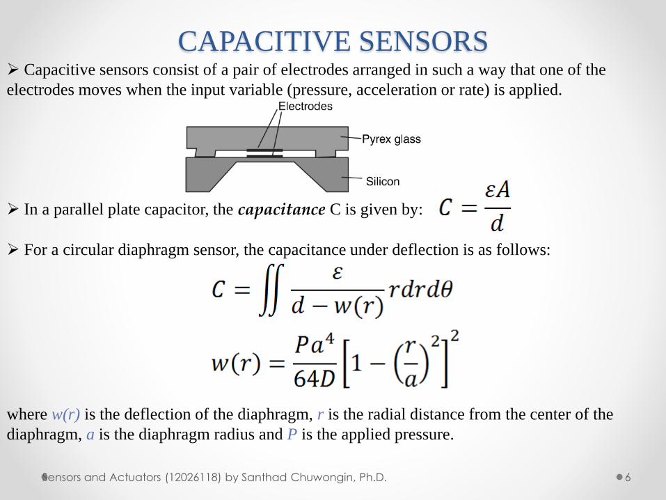
CAPACITIVE SENSORS
6Sensors and Actuators (12026118) by Santhad Chuwongin, Ph.D.
➢ Capacitive sensors consist of a pair of electrodes arranged in such a way that one of the
electrodes moves when the input variable (pressure, acceleration or rate) is applied.
➢ In a parallel plate capacitor, the capacitance C is given by:
➢ For a circular diaphragm sensor, the capacitance under deflection is as follows:
where w(r) is the deflection of the diaphragm, r is the radial distance from the center of the
diaphragm, a is the diaphragm radius and P is the applied pressure.
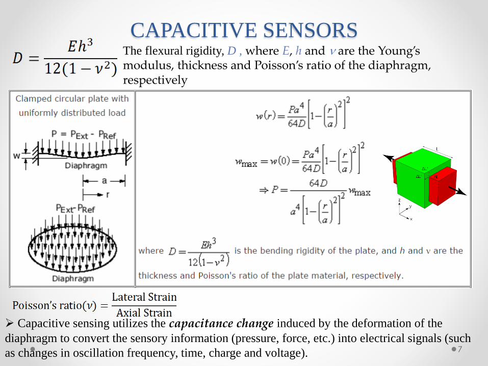
CAPACITIVE SENSORS
7
The flexural rigidity, D , where E, h and are the Young’s modulus, thickness and Poisson’s ratio of the diaphragm, respectively
➢ Capacitive sensing utilizes the capacitance change induced by the deformation of the
diaphragm to convert the sensory information (pressure, force, etc.) into electrical signals (such
as changes in oscillation frequency, time, charge and voltage).
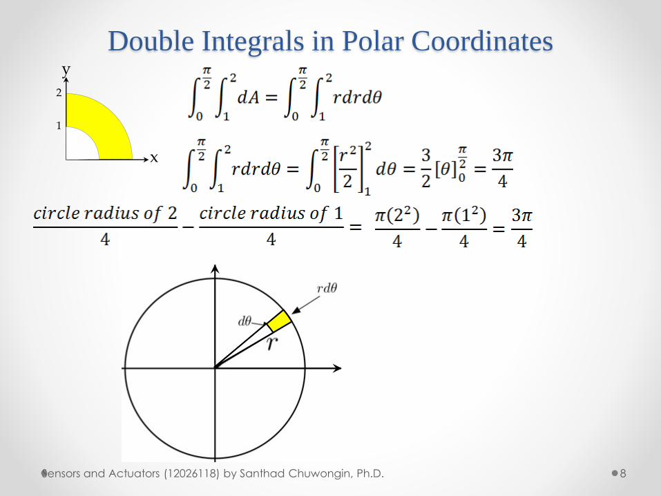
Double Integrals in Polar Coordinates
8Sensors and Actuators (12026118) by Santhad Chuwongin, Ph.D.
1
2
y
x
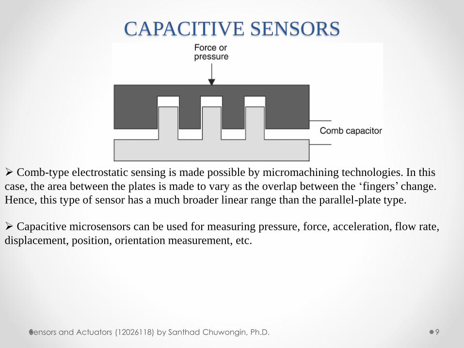
CAPACITIVE SENSORS
9Sensors and Actuators (12026118) by Santhad Chuwongin, Ph.D.
➢ Comb-type electrostatic sensing is made possible by micromachining technologies. In this
case, the area between the plates is made to vary as the overlap between the ‘fingers’ change.
Hence, this type of sensor has a much broader linear range than the parallel-plate type.
➢ Capacitive microsensors can be used for measuring pressure, force, acceleration, flow rate,
displacement, position, orientation measurement, etc.
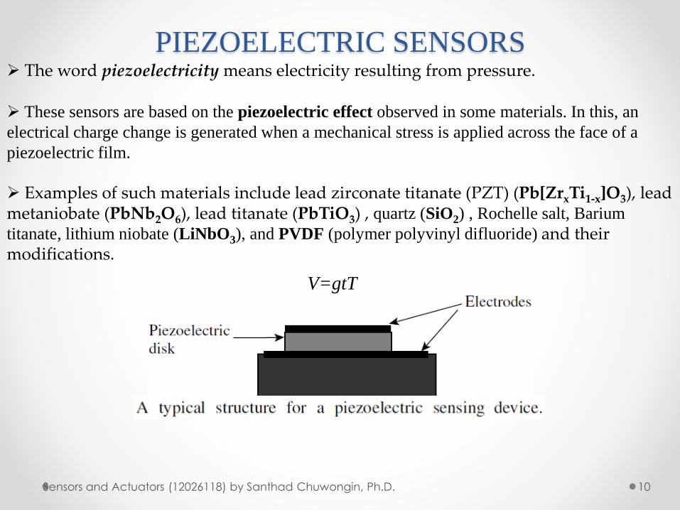
PIEZOELECTRIC SENSORS
10Sensors and Actuators (12026118) by Santhad Chuwongin, Ph.D.
➢ The word piezoelectricity means electricity resulting from pressure.
➢ These sensors are based on the piezoelectric effect observed in some materials. In this, an
electrical charge change is generated when a mechanical stress is applied across the face of a
piezoelectric film.
➢ Examples of such materials include lead zirconate titanate (PZT) (Pb[ZrxTi1-x]O3), lead metaniobate (PbNb2O6), lead titanate (PbTiO3) , quartz (SiO2) , Rochelle salt, Barium
titanate, lithium niobate (LiNbO3), and PVDF (polymer polyvinyl difluoride) and their modifications.
V=gtT
PIEZOELECTRIC SENSORS
11Sensors and Actuators (12026118) by Santhad Chuwongin, Ph.D.
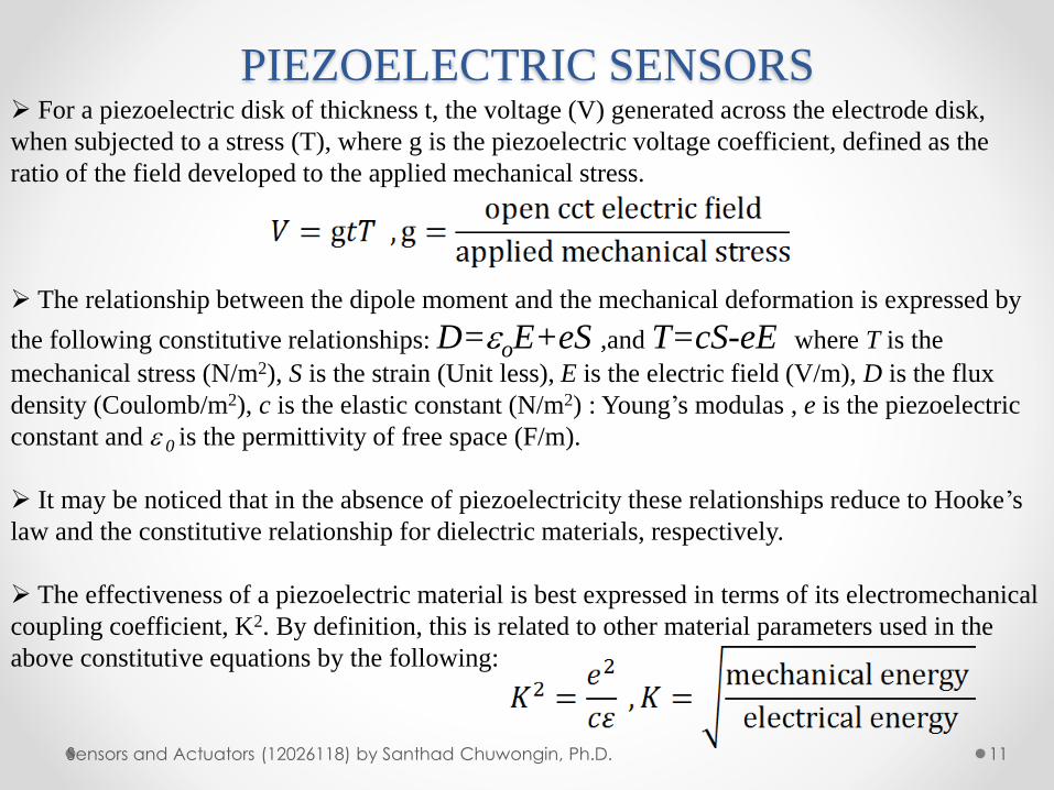
➢ For a piezoelectric disk of thickness t, the voltage (V) generated across the electrode disk,
when subjected to a stress (T), where g is the piezoelectric voltage coefficient, defined as the
ratio of the field developed to the applied mechanical stress.
➢ The relationship between the dipole moment and the mechanical deformation is expressed by
the following constitutive relationships: D=oE+eS ,and T=cS-eE where T is the
mechanical stress (N/m2), S is the strain (Unit less), E is the electric field (V/m), D is the flux
density (Coulomb/m2), c is the elastic constant (N/m2) : Young’s modulas , e is the piezoelectric
constant and 0 is the permittivity of free space (F/m).
➢ It may be noticed that in the absence of piezoelectricity these relationships reduce to Hooke’s
law and the constitutive relationship for dielectric materials, respectively.
➢ The effectiveness of a piezoelectric material is best expressed in terms of its electromechanical
coupling coefficient, K2. By definition, this is related to other material parameters used in the
above constitutive equations by the following:
PIEZOELECTRIC SENSORS
12Sensors and Actuators (12026118) by Santhad Chuwongin, Ph.D.
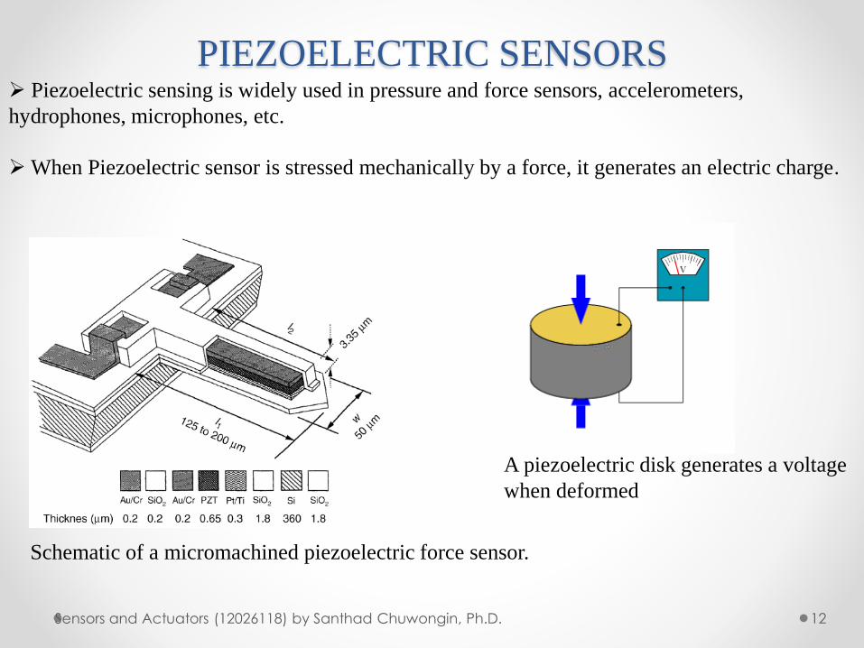
➢ Piezoelectric sensing is widely used in pressure and force sensors, accelerometers,
hydrophones, microphones, etc.
➢When Piezoelectric sensor is stressed mechanically by a force, it generates an electric charge.
Schematic of a micromachined piezoelectric force sensor.
A piezoelectric disk generates a voltage
when deformed
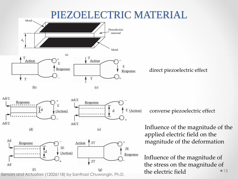
PIEZOELECTRIC MATERIAL
13Sensors and Actuators (12026118) by Santhad Chuwongin, Ph.D.
direct piezoelectric effect
converse piezoelectric effect
Influence of the magnitude of the applied electric field on the magnitude of the deformation
Influence of the magnitude of the stress on the magnitude of the electric field
PIEZOELECTRIC EFFECT
14Vetelino, J., Reghu, A. (2011). Introduction to Sensors. Boca Raton: CRC Press
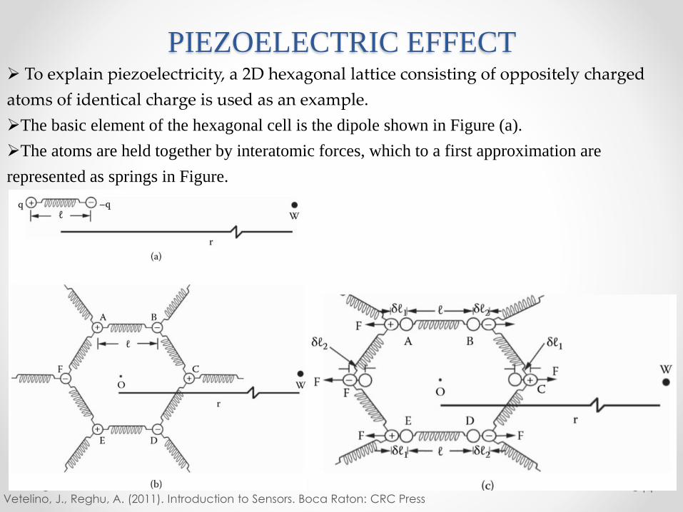
➢ To explain piezoelectricity, a 2D hexagonal lattice consisting of oppositely charged
atoms of identical charge is used as an example.
➢The basic element of the hexagonal cell is the dipole shown in Figure (a).
➢The atoms are held together by interatomic forces, which to a first approximation are
represented as springs in Figure.
PIEZOELECTRIC EFFECT
15Vetelino, J., Reghu, A. (2011). Introduction to Sensors. Boca Raton: CRC Press
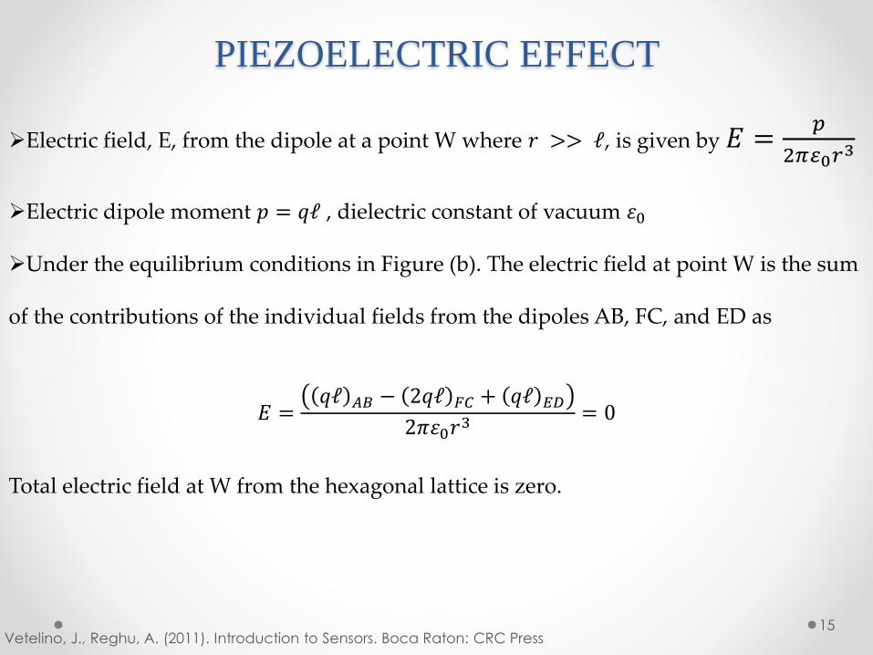
➢Electric field, E, from the dipole at a point W where 𝑟 >> ℓ, is given by 𝐸 =𝑝
2𝜋 0𝑟3
➢Electric dipole moment 𝑝 = 𝑞ℓ , dielectric constant of vacuum 휀0
➢Under the equilibrium conditions in Figure (b). The electric field at point W is the sum
of the contributions of the individual fields from the dipoles AB, FC, and ED as
𝐸 =𝑞ℓ 𝐴𝐵 − 2𝑞ℓ 𝐹𝐶 + 𝑞ℓ 𝐸𝐷
2𝜋휀0𝑟3 = 0
Total electric field at W from the hexagonal lattice is zero.
PIEZOELECTRIC EFFECT
16Vetelino, J., Reghu, A. (2011). Introduction to Sensors. Boca Raton: CRC Press
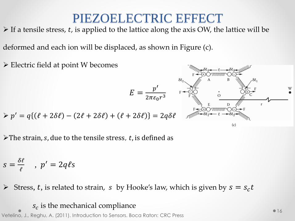
➢ If a tensile stress, 𝑡, is applied to the lattice along the axis OW, the lattice will be
deformed and each ion will be displaced, as shown in Figure (c).
➢ Electric field at point W becomes
𝐸 =𝑝′
2𝜋 0𝑟3
➢ 𝑝′ = 𝑞 ℓ + 2𝛿ℓ − 2ℓ + 2𝛿ℓ + ℓ + 2𝛿ℓ = 2𝑞𝛿ℓ
➢The strain, 𝑠, due to the tensile stress, 𝑡, is defined as
𝑠 =𝛿ℓ
ℓ, 𝑝′ = 2𝑞ℓs
➢ Stress, 𝑡, is related to strain, 𝑠 by Hooke’s law, which is given by 𝑠 = 𝑠𝑐𝑡
𝑠𝑐 is the mechanical compliance
PIEZOELECTRIC EFFECT
17Vetelino, J., Reghu, A. (2011). Introduction to Sensors. Boca Raton: CRC Press
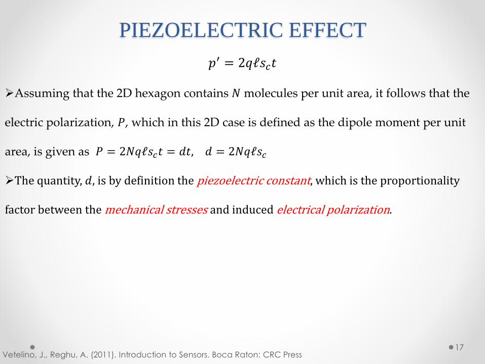
𝑝′ = 2𝑞ℓ𝑠𝑐𝑡
➢Assuming that the 2D hexagon contains 𝑁 molecules per unit area, it follows that the
electric polarization, 𝑃, which in this 2D case is defined as the dipole moment per unit
area, is given as 𝑃 = 2𝑁𝑞ℓ𝑠𝑐𝑡 = 𝑑𝑡, 𝑑 = 2𝑁𝑞ℓ𝑠𝑐
➢The quantity, 𝑑, is by definition the piezoelectric constant, which is the proportionality
factor between the mechanical stresses and induced electrical polarization.
PIEZOELECTRIC EFFECT
18Vetelino, J., Reghu, A. (2011). Introduction to Sensors. Boca Raton: CRC Press
𝑝′ = 2𝑞ℓ𝑠𝑐𝑡
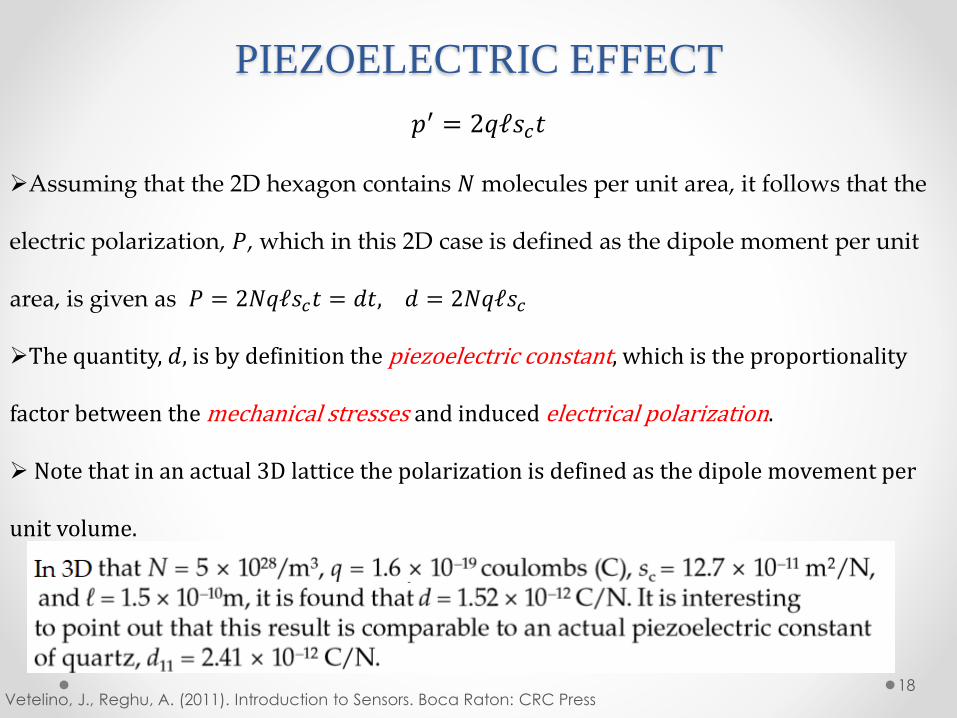
➢Assuming that the 2D hexagon contains 𝑁 molecules per unit area, it follows that the
electric polarization, 𝑃, which in this 2D case is defined as the dipole moment per unit
area, is given as 𝑃 = 2𝑁𝑞ℓ𝑠𝑐𝑡 = 𝑑𝑡, 𝑑 = 2𝑁𝑞ℓ𝑠𝑐
➢The quantity, 𝑑, is by definition the piezoelectric constant, which is the proportionality
factor between the mechanical stresses and induced electrical polarization.
➢ Note that in an actual 3D lattice the polarization is defined as the dipole movement per
unit volume.
MAGNETOSTRICTIVE SENSORS
19Sensors and Actuators (12026118) by Santhad Chuwongin, Ph.D.
➢Magnetostrictive materials can convert magnetic energy into kinetic energy, or the reverse,
and are used to build actuators and sensors.
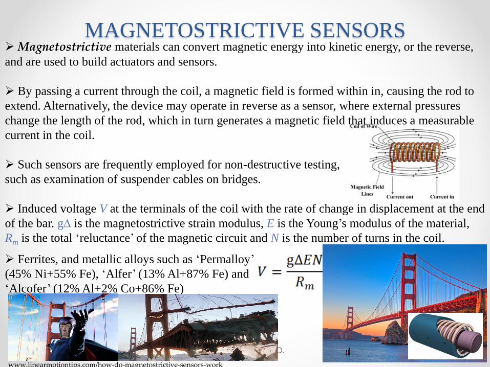
➢ By passing a current through the coil, a magnetic field is formed within in, causing the rod to
extend. Alternatively, the device may operate in reverse as a sensor, where external pressures
change the length of the rod, which in turn generates a magnetic field that induces a measurable
current in the coil.
➢ Such sensors are frequently employed for non-destructive testing,
such as examination of suspender cables on bridges.
➢ Induced voltage V at the terminals of the coil with the rate of change in displacement at the end
of the bar. g is the magnetostrictive strain modulus, E is the Young’s modulus of the material,
Rm is the total ‘reluctance’ of the magnetic circuit and N is the number of turns in the coil.
➢ Ferrites, and metallic alloys such as ‘Permalloy’
(45% Ni+55% Fe), ‘Alfer’ (13% Al+87% Fe) and
‘Alcofer’ (12% Al+2% Co+86% Fe)
www.linearmotiontips.com/how-do-magnetostrictive-sensors-work
PIEZORESISTIVE SENSORS
20
➢ The piezoresistive effect is a change in the electrical resistivity of a semiconductor or
metal when mechanical strain is applied. In contrast to the piezoelectric effect, the piezoresistive
effect causes a change only in electrical resistance (R), not in electric potential (Not V).
➢ In silicon, produces a larger resistance change than that under an applied stress in a typical
conductor. Ex. the material is elongated 0.1% by stretching, the typical metallic resistors would
change by ~0.2 %, but the resistance of silicon would change by ~10 %.
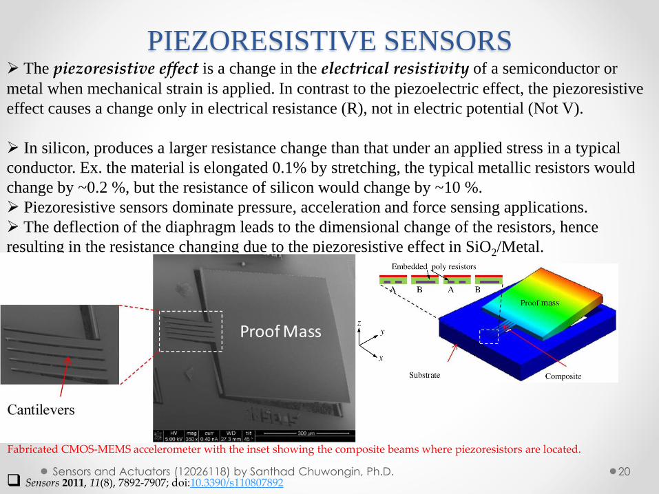
➢ Piezoresistive sensors dominate pressure, acceleration and force sensing applications.
➢ The deflection of the diaphragm leads to the dimensional change of the resistors, hence
resulting in the resistance changing due to the piezoresistive effect in SiO2/Metal.
Fabricated CMOS-MEMS accelerometer with the inset showing the composite beams where piezoresistors are located.
❑ Sensors 2011, 11(8), 7892-7907; doi:10.3390/s110807892Sensors and Actuators (12026118) by Santhad Chuwongin, Ph.D.
PIEZORESISTIVE SENSORS
21Sensors and Actuators (12026118) by Santhad Chuwongin, Ph.D.
➢ where R is the change of the resistance, R is the original resistance, is the Poison ratio, l is
the length change of the resistor, l is the original length of the resistor and and represent the
resistivity change and resistivity of the resistor, respectively.
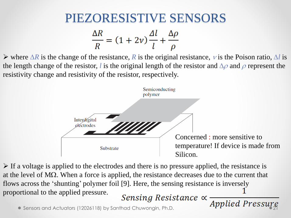
➢ If a voltage is applied to the electrodes and there is no pressure applied, the resistance is
at the level of M. When a force is applied, the resistance decreases due to the current that
flows across the ‘shunting’ polymer foil [9]. Here, the sensing resistance is inversely
proportional to the applied pressure.
Concerned : more sensitive to
temperature! If device is made from
Silicon.
OPTICAL SENSORS
22Sensors and Actuators (12026118) by Santhad Chuwongin, Ph.D.
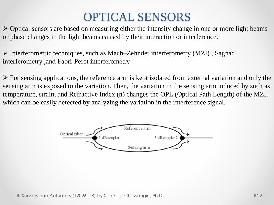
➢ Optical sensors are based on measuring either the intensity change in one or more light beams
or phase changes in the light beams caused by their interaction or interference.
➢ Interferometric techniques, such as Mach–Zehnder interferometry (MZI) , Sagnac
interferometry ,and Fabri-Perot interferometry
➢ For sensing applications, the reference arm is kept isolated from external variation and only the
sensing arm is exposed to the variation. Then, the variation in the sensing arm induced by such as
temperature, strain, and Refractive Index (n) changes the OPL (Optical Path Length) of the MZI,
which can be easily detected by analyzing the variation in the interference signal.
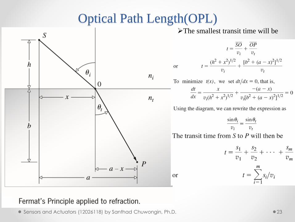
Optical Path Length(OPL)
23Sensors and Actuators (12026118) by Santhad Chuwongin, Ph.D.
➢The smallest transit time will be
Optical Path Length(OPL)
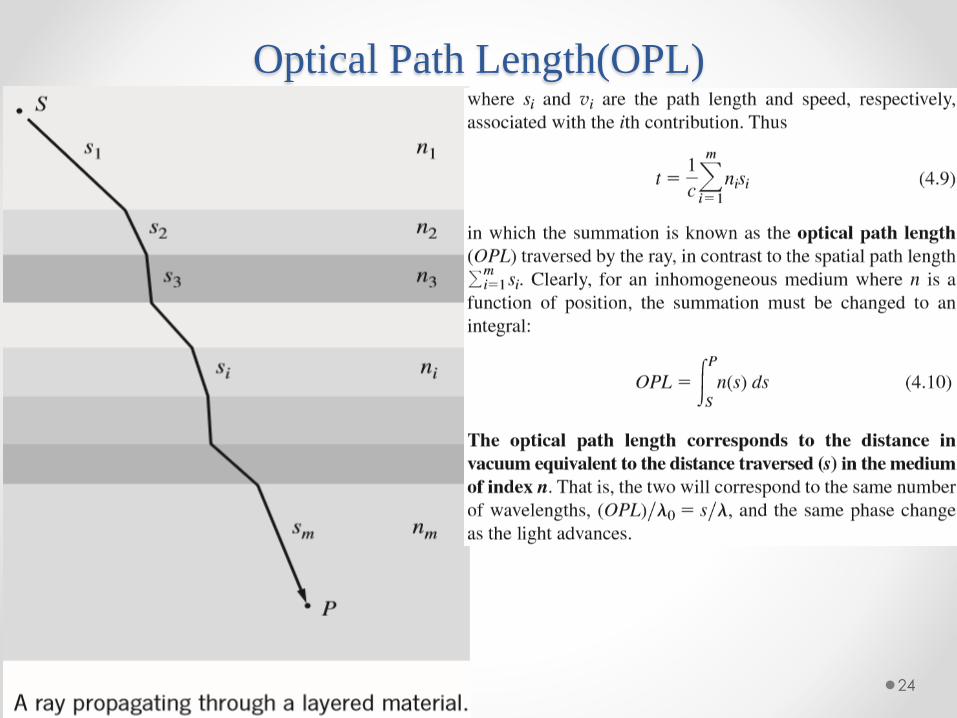
24
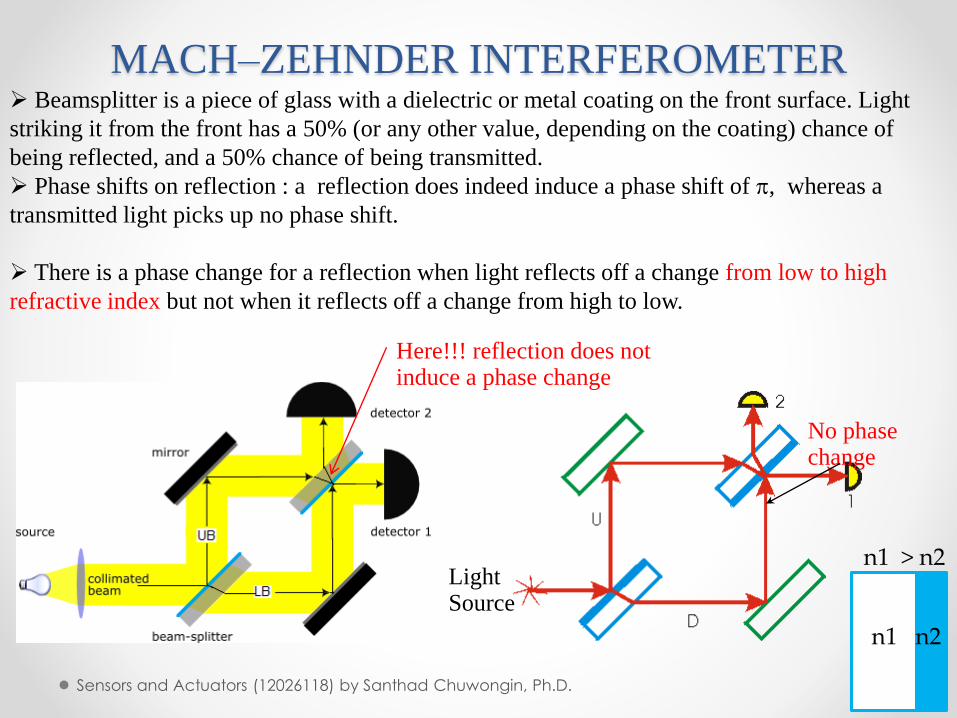
MACH–ZEHNDER INTERFEROMETER
25Sensors and Actuators (12026118) by Santhad Chuwongin, Ph.D.
➢ Beamsplitter is a piece of glass with a dielectric or metal coating on the front surface. Light
striking it from the front has a 50% (or any other value, depending on the coating) chance of
being reflected, and a 50% chance of being transmitted.
➢ Phase shifts on reflection : a reflection does indeed induce a phase shift of , whereas a
transmitted light picks up no phase shift.
➢ There is a phase change for a reflection when light reflects off a change from low to high
refractive index but not when it reflects off a change from high to low.
Here!!! reflection does not induce a phase change
No phase change
Light Source
n1 > n2
n1 n2
MACH–ZEHNDER INTERFEROMETER
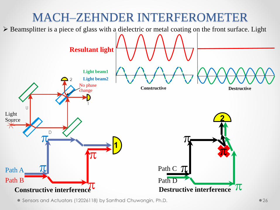
26Sensors and Actuators (12026118) by Santhad Chuwongin, Ph.D.
➢ Beamsplitter is a piece of glass with a dielectric or metal coating on the front surface. Light
No phase change
Light Source
Path D
Path C
2
Path A
Path B
1
Constructive interference Destructive interference
Resultant light
Light beam1
Light beam2
Constructive Destructive
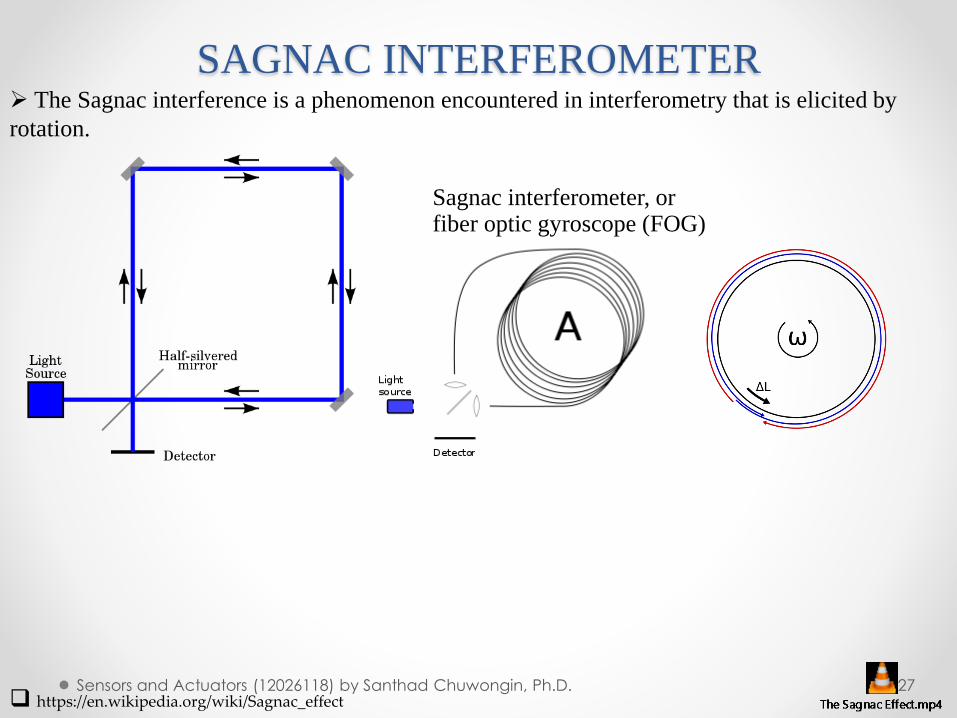
SAGNAC INTERFEROMETER
27Sensors and Actuators (12026118) by Santhad Chuwongin, Ph.D.
➢ The Sagnac interference is a phenomenon encountered in interferometry that is elicited by
rotation.
❑ https://en.wikipedia.org/wiki/Sagnac_effect
Sagnac interferometer, or fiber optic gyroscope (FOG)
SAGNAC INTERFEROMETER
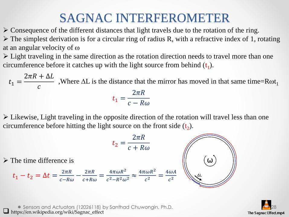
28Sensors and Actuators (12026118) by Santhad Chuwongin, Ph.D.
➢ Consequence of the different distances that light travels due to the rotation of the ring.
➢ The simplest derivation is for a circular ring of radius R, with a refractive index of 1, rotating
at an angular velocity of
➢ Light traveling in the same direction as the rotation direction needs to travel more than one
circumference before it catches up with the light source from behind (t1).
➢ Likewise, Light traveling in the opposite direction of the rotation will travel less than one
circumference before hitting the light source on the front side (t2).
➢ The time difference is
❑ https://en.wikipedia.org/wiki/Sagnac_effect
𝑡1 =2𝜋𝑅 + ∆𝐿
𝑐,Where L is the distance that the mirror has moved in that same time=Rt1
𝑡1 =2𝜋𝑅
𝑐 − 𝑅𝜔
𝑡2 =2𝜋𝑅
𝑐 + 𝑅𝜔
𝑡1 − 𝑡2 = ∆𝑡 =2𝜋𝑅
𝑐−𝑅𝜔−
2𝜋𝑅
𝑐+𝑅𝜔=
4𝜋𝜔𝑅2
𝑐2−𝑅2𝜔2 ≈4𝜋𝜔𝑅2
𝑐2=
4𝜔𝐴
𝑐2
SAGNAC INTERFEROMETER
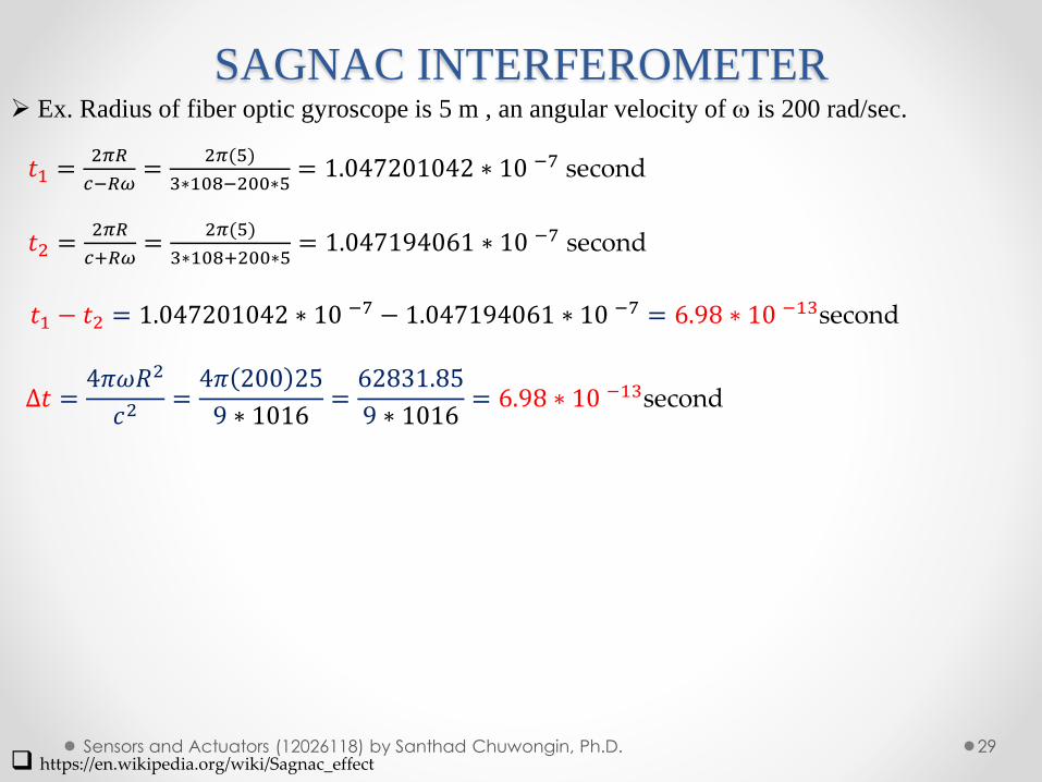
29Sensors and Actuators (12026118) by Santhad Chuwongin, Ph.D.
➢ Ex. Radius of fiber optic gyroscope is 5 m , an angular velocity of is 200 rad/sec.
❑ https://en.wikipedia.org/wiki/Sagnac_effect
𝑡1 =2𝜋𝑅
𝑐−𝑅𝜔=
2𝜋(5)
3∗108−200∗5= 1.047201042 ∗ 10 −7 second
∆𝑡 =4𝜋𝜔𝑅2
𝑐2=4𝜋 200 25
9 ∗ 1016=62831.85
9 ∗ 1016= 6.98 ∗ 10 −13second
𝑡2 =2𝜋𝑅
𝑐+𝑅𝜔=
2𝜋(5)
3∗108+200∗5= 1.047194061 ∗ 10 −7 second
𝑡1 − 𝑡2 = 1.047201042 ∗ 10 −7 − 1.047194061 ∗ 10 −7 = 6.98 ∗ 10 −13second
RESONANT SENSORS
30Sensors and Actuators (12026118) by Santhad Chuwongin, Ph.D.
➢ Resonant sensors are based on measuring the resonant freq. of the mechanical vibration of
beams or diaphragms. The applied strain causes changes in the resonant freq. (similar to a guitar
string), enabling measurement of input variables such as pressure, acceleration, rate ,and
temperature.
➢In a resonant sensor, the strain caused by pressure on the diaphragm leads to variation of its
natural frequency.
➢As an example, the natural resonant frequency of a flexure resonator with both ends fixed can
be obtained from the following
➢where f is the natural frequency of the fundamental oscillating mode, l the resonator length, h
the resonator thickness, E the Young’s modulus, the density of the diaphragm material and the
strain generated inside the resonator structure.
RESONANT SENSORS
31Sensors and Actuators (12026118) by Santhad Chuwongin, Ph.D.
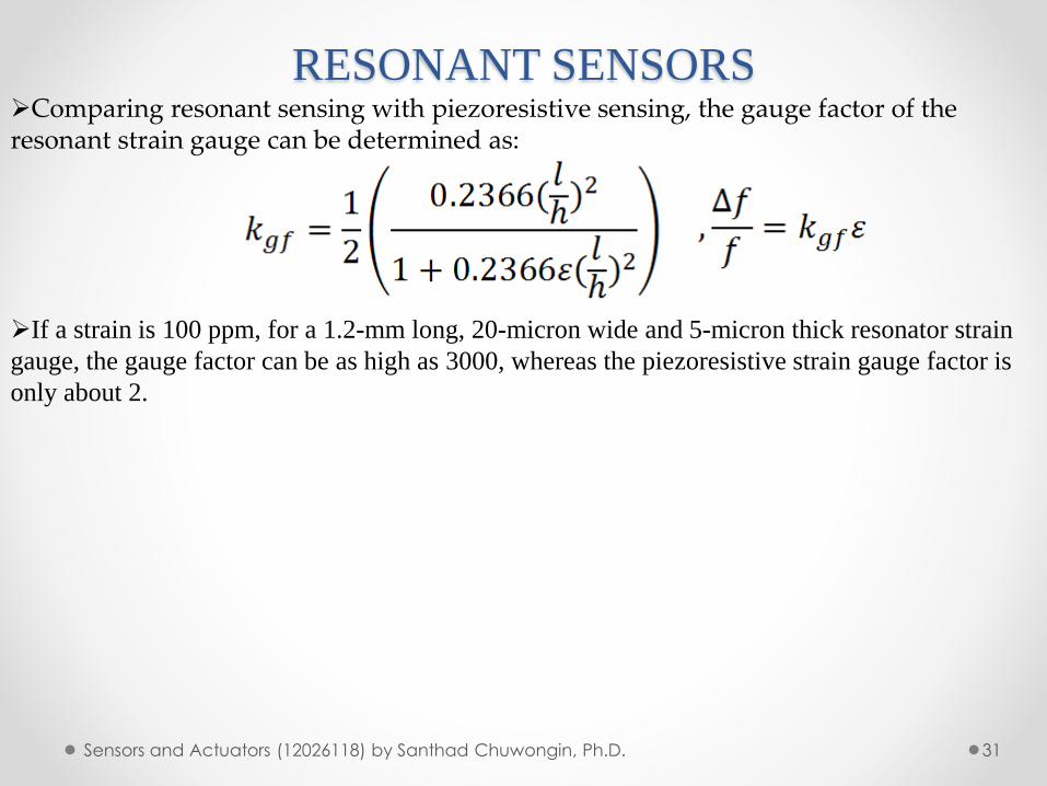
➢Comparing resonant sensing with piezoresistive sensing, the gauge factor of the resonant strain gauge can be determined as:
➢If a strain is 100 ppm, for a 1.2-mm long, 20-micron wide and 5-micron thick resonator strain
gauge, the gauge factor can be as high as 3000, whereas the piezoresistive strain gauge factor is
only about 2.
Questions
32Sensors and Actuators (12026118) by Santhad Chuwongin, Ph.D.
1. จากบทเรียนเร่ือง Capacitive sensors จงหาวา่ input&output คือส่ิงใดa) พ้ืนท่ีและค่าความจุท่ีเปล่ียนแปลงb) แรงกดและระยะระหวา่งขั้วไฟฟ้าท่ีเปล่ียนแปลงc) แรงกดและค่าความจุท่ีเปล่ียนแปลงd) พ้ืนท่ีและระยะระหวา่งขั้วไฟฟ้าท่ีเปล่ียนแปลง
2. จากบทเรียนเร่ือง circular diaphragm capacitive sensor เหตุใดจึงมีความซบัซอ้นในการค านวนa) ค่าพ้ืนท่ีไม่คงท่ีb) ค่าความจุไม่คงท่ีc) ค่า ของตวักลางไม่คงท่ีd) ค่าระยะระหวา่งขั้วไฟฟ้าไม่คงท่ี
3. จากบทเรียนเร่ือง Comb capacitor ค่าความจุท่ีเปล่ียนแปลงเป็นผลมาจากส่ิงใดเป็นส าคญัa) ค่าพ้ืนท่ีซอ้นกนัของขั้วไฟฟ้าb) ค่าความน าไฟฟ้าของขั้วไฟฟ้าc) ค่า ของตวักลางเปล่ียนแปลงd) ค่าระยะระหวา่งขั้วไฟฟ้า
Questions
33Sensors and Actuators (12026118) by Santhad Chuwongin, Ph.D.
4. จากบทเรียนเร่ือง piezoelectric sensors ขอ้ใดถูกตอ้งa) กระแสไฟฟ้าท่ีเกิดข้ึนมาจากแรงกดท่ีกระท ากบั piezoresistive material
b) กระแสไฟฟ้าท่ีเกิดข้ึนมาจากแรงดนัไฟฟ้าท่ีกระท ากบั PbTiO3
c) แรงดนัไฟฟ้าท่ีเกิดข้ึนมาจากแรงกดท่ีกระท ากบั piezoresistive material
d) แรงดนัไฟฟ้าท่ีเกิดข้ึนมาจากแรงกดท่ีกระท ากบั PbTiO3
5. จากบทเรียนเร่ือง piezoelectric sensors ขอ้ใดไม่ถูกตอ้งa) เก่ียวขอ้งกบัค่า Young’s modulus
b) เก่ียวขอ้งกบัค่าสนามไฟฟ้าc) เก่ียวขอ้งกบัค่า Poisson’s ratio
d) เก่ียวขอ้งกบัค่า elastic constant
6. จากบทเรียนเร่ือง piezoelectric sensors ขอ้ใดไม่เก่ียวขอ้งa) Pressure sensor ใชห้ลกัการ piezoelectric effect
b) piezoelectric sensors ถูกน ามาใชม้าใน Bio-chemical sensor
c) hydrophones และ microphones บางประเภทคือ piezoelectric sensors
d) ถา้ไม่มีสนามไฟฟ้า piezoelectric effect จะกลายเป็นกฎของ Hooke
Questions
34Sensors and Actuators (12026118) by Santhad Chuwongin, Ph.D.
7. จากบทเรียนเร่ือง Magnetostrictive sensors ขอ้ใดถูกตอ้งa) แรงกดเปล่ียนความยาวของวสัดุท าใหเ้กิดสนามแม่เหลก็แลว้เหน่ียวน าใหเ้กิดกระแสไฟฟ้าb) อุณหภูมิเปล่ียนความยาวของวสัดุท าใหเ้กิดสนามแม่เหลก็แลว้เหน่ียวน าใหเ้กิดกระแสไฟฟ้าc) แรงดนัไฟฟ้าเปล่ียนความยาวของวสัดุท าใหเ้กิดสนามแม่เหลก็แลว้เหน่ียวน าใหเ้กิดกระแสไฟฟ้าd) ความเขม้สนามแม่เหลก็เปล่ียนความยาวของวสัดุและเหน่ียวน าใหเ้กิดกระแสไฟฟ้า
8. เหตุใด Piezoresistive sensor จึงนิยมท าจากสารก่ึงตวัน ามากกวา่โลหะa) สารก่ึงตวัน ามีความตา้นทานสูงกวา่โลหะb) สารก่ึงตวัน ามีความตา้นทานเปล่ียนแปลงสูงกวา่โลหะเม่ือถูกยดืออกc) สารก่ึงตวัน ามีความตา้นทานเปล่ียนแปลงต ่ากวา่โลหะเม่ือถูกยดืออกd) สารก่ึงตวัน ามีค่า Young ‘s modulus สูงกวา่โลหะ