SENSOR-TO-SHOOTER C2ISR INTEGRATION WITH JOINT BATTLESPACE INFOSPHERE… · SENSOR-TO-SHOOTER C2ISR...
35
AFRL-IF-RS-TR-2005-419 Final Technical Report January 2006 SENSOR-TO-SHOOTER C2ISR INTEGRATION WITH JOINT BATTLESPACE INFOSPHERE: JBI CLIENT ADAPTERS General Dynamics APPROVED FOR PUBLIC RELEASE; DISTRIBUTION UNLIMITED. AIR FORCE RESEARCH LABORATORY INFORMATION DIRECTORATE ROME RESEARCH SITE ROME, NEW YORK
Transcript of SENSOR-TO-SHOOTER C2ISR INTEGRATION WITH JOINT BATTLESPACE INFOSPHERE… · SENSOR-TO-SHOOTER C2ISR...

AFRL-IF-RS-TR-2005-419
Final Technical Report January 2006 SENSOR-TO-SHOOTER C2ISR INTEGRATION WITH JOINT BATTLESPACE INFOSPHERE: JBI CLIENT ADAPTERS
General Dynamics
APPROVED FOR PUBLIC RELEASE; DISTRIBUTION UNLIMITED.
AIR FORCE RESEARCH LABORATORY INFORMATION DIRECTORATE
ROME RESEARCH SITE ROME, NEW YORK

STINFO FINAL REPORT This report has been reviewed by the Air Force Research Laboratory, Information Directorate, Public Affairs Office (IFOIPA) and is releasable to the National Technical Information Service (NTIS). At NTIS it will be releasable to the general public, including foreign nations. AFRL-IF-RS-TR-2005-419 has been reviewed and is approved for publication APPROVED: /s/
JUSTIN E. SORICE Project Engineer
FOR THE DIRECTOR: /s/
JAMES W. CUSACK Chief, Information Systems Division Information Directorate

REPORT DOCUMENTATION PAGE Form Approved
OMB No. 074-0188 Public reporting burden for this collection of information is estimated to average 1 hour per response, including the time for reviewing instructions, searching existing data sources, gathering and maintaining the data needed, and completing and reviewing this collection of information. Send comments regarding this burden estimate or any other aspect of this collection of information, including suggestions for reducing this burden to Washington Headquarters Services, Directorate for Information Operations and Reports, 1215 Jefferson Davis Highway, Suite 1204, Arlington, VA 22202-4302, and to the Office of Management and Budget, Paperwork Reduction Project (0704-0188), Washington, DC 20503 1. AGENCY USE ONLY (Leave blank)
2. REPORT DATEJANUARY 2006
3. REPORT TYPE AND DATES COVERED Final Jan 2005 – Sep 2005
4. TITLE AND SUBTITLE SENSOR-TO-SHOOTER C2ISR INTEGRATION WITH JOINT BATTLESPACE INFOSPHERE: JBI CLIENT ADAPTERS
6. AUTHOR(S) Joseph Lerner, Jonathan Shaw, Nick Kowalchuk, Mike Sinsabaugh
5. FUNDING NUMBERS C - FA8750-04-C-0278 PE - 63789F PR - 487B TA - 04 WU - 01
7. PERFORMING ORGANIZATION NAME(S) AND ADDRESS(ES) Prime SubGeneral Dynamics Sensis Corporation 8201 E. McDowell Road 85 Collamer Crossings Scottsdale Arizona 85257 East Syracuse New York 13057
8. PERFORMING ORGANIZATION REPORT NUMBER
N/A
9. SPONSORING / MONITORING AGENCY NAME(S) AND ADDRESS(ES) Air Force Research Laboratory/IFSE 525 Brooks Road Rome New York 13441-4505
10. SPONSORING / MONITORING AGENCY REPORT NUMBER
AFRL-IF-RS-TR-2005-419
11. SUPPLEMENTARY NOTES AFRL Project Engineer: Justin E. Sorice, 1Lt, USAF/IFSE/(315) 330-4835/ [email protected]
12a. DISTRIBUTION / AVAILABILITY STATEMENT APPROVED FOR PUBLIC RELEASE; DISTRIBUTION UNLIMITED.
12b. DISTRIBUTION CODE
13. ABSTRACT (Maximum 200 Words)This report provides the results of the detailed design and implementation phase, Phase II, of the JBI Client Adapter program. This effort consisted of the work associated with developing the client applications and adapters for selected legacy systems to enable them to interact through the Infosphere using the Joint Battlespace Infosphere, JBI, Mercury Client Application Programming Interface, CAPI, compliant interfaces. This report is relevant to all DoD entities seeking technical solutions for interoperable information dissemination and sharing among Command & Control, Intelligence, Surveillance and Reconnaissance, C2ISR, mission applications in a heterogeneous, distributed environment.
15. NUMBER OF PAGES35
14. SUBJECT TERMS Joint Battlespace Infosphere; Automated Deep Operations Coordination System; Distributed Command Ground Station; Command and Control Personnel Center 16. PRICE CODE
17. SECURITY CLASSIFICATION OF REPORT
UNCLASSIFIED
18. SECURITY CLASSIFICATION OF THIS PAGE
UNCLASSIFIED
19. SECURITY CLASSIFICATION OF ABSTRACT
UNCLASSIFIED
20. LIMITATION OF ABSTRACT
ULNSN 7540-01-280-5500 Standard Form 298 (Rev. 2-89)
Prescribed by ANSI Std. Z39-18 298-102

Abstract This report provides the results of the detailed design and implementation phase (Phase II) of the JBI Client Adapter program. This effort consisted of the work associated with developing the client applications and adapters for selected legacy systems to enable them to interact through the Infosphere using the Joint Battlespace Infosphere (JBI) Mercury Client Application Programming Interface (CAPI) compliant interfaces. This report is relevant to all DoD entities seeking technical solutions for interoperable information dissemination and sharing among Command & Control, Intelligence, Surveillance, and Reconnaissance (C2ISR) mission applications in a heterogeneous, distributed environment.
During the period of performance for this effort detailed design artifacts were produced and reviewed at General Dynamics C4 Systems and Sensis Corporation, and reviewed by AFRL principals. Subsequently the demonstration software was coded, unit tested, and integrated. The project culminated with a live demonstration at GDC4S in Scottsdale, Arizona on Wednesday August 31, 2005.
As evidenced by the final demonstration, the overall project was successful. The legacy systems were joined through JBI into an operationally compelling and realistic scenario. The demonstration served as a catalyst for key Infosphere stakeholders to engage in extensive, substantive, and fruitful exploration and discussion as to the benefits of the Infosphere/adapter approach. These and other outcomes of the project are captured in this document.
i

Table of Contents 1 Summary .................................................................................................................................. 1 2 Introduction .............................................................................................................................. 1
2.1 Project Execution............................................................................................................... 1 2.2 Subject ............................................................................................................................... 2 2.3 Purpose .............................................................................................................................. 2 2.4 Scope ................................................................................................................................. 2 2.5 Report Structure................................................................................................................. 2
3 Methods, Assumptions, and Procedures .................................................................................. 3 3.1 Demonstration Scenario and Requirements ...................................................................... 4 3.2 Detailed Design ................................................................................................................. 6
3.2.1 Define Adapter State Diagrams .............................................................................................................6 3.2.2 Define Information Object Schemas......................................................................................................6 3.2.3 Define Information Mappings................................................................................................................6
3.3 Implementation.................................................................................................................. 6 3.3.1 ADOCS Adapter ....................................................................................................................................7 3.3.2 C2PC Adapter........................................................................................................................................9 3.3.3 Link16 Adapter ....................................................................................................................................10 3.3.4 SOF PDA.............................................................................................................................................12 3.3.5 CONUS Node ......................................................................................................................................14 3.3.6 DCGS Adapter.....................................................................................................................................15
3.4 Final Demonstration ........................................................................................................ 16 4 Results and Discussion........................................................................................................... 16
4.1 Final Demonstration Results ........................................................................................... 17 4.2 Project Metrics................................................................................................................. 23
4.2.1 Qualitative Value-Added Factors: .......................................................................................................24 4.2.2 Quantitative Value-Added Factors: .....................................................................................................24
5 Concluding Remarks .............................................................................................................. 24 6 Recommendations .................................................................................................................. 26 7 Symbols, Abbreviations, and Acronyms................................................................................ 28
ii

List of Figures
Figure 1: Execution Schedule ......................................................................................................... 2 Figure 2: Demonstration Scenario .................................................................................................. 4 Figure 3: High-Level System Architecture..................................................................................... 5 Figure 4: ADOCS Adapter Architecture......................................................................................... 7 Figure 5: C2PC Adapter Architecture............................................................................................. 9 Figure 6: Link16 Simulation Environment Configuration............................................................ 11 Figure 7: Link16 Adapter Design ................................................................................................. 12 Figure 8: SOF PDA Design .......................................................................................................... 13 Figure 9: SOF PDA GUI............................................................................................................... 14 Figure 10: CONUS Node Design ................................................................................................. 15 Figure 11: DCGS Adapter Design ................................................................................................ 16 Figure 12: Demonstration Hardware ............................................................................................ 18 Figure 13: Demonstration Software Configuration ...................................................................... 19 Figure 14: Demonstration Presentation ........................................................................................ 22
List of Tables
Table 1 Design, Engineering, Or Process Specifications Delivered............................................... 3 Table 2 ADOCS Adapter Stimulus................................................................................................. 8 Table 3 C2PC Adapter Stimulus................................................................................................... 10 Table 4 Final Demonstration Attendees ....................................................................................... 17 Table 5 Software Parts/License List ............................................................................................. 20 Table 6 Scenario Steps.................................................................................................................. 22 Table 7 Infosphere Value Add...................................................................................................... 25 Table 8 Lessons Learned .............................................................................................................. 26 Table 9 Infosphere Recommendations.......................................................................................... 27
iii
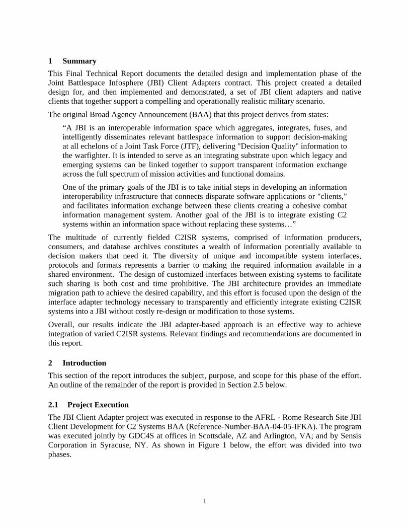
1 Summary This Final Technical Report documents the detailed design and implementation phase of the Joint Battlespace Infosphere (JBI) Client Adapters contract. This project created a detailed design for, and then implemented and demonstrated, a set of JBI client adapters and native clients that together support a compelling and operationally realistic military scenario.
The original Broad Agency Announcement (BAA) that this project derives from states:
“A JBI is an interoperable information space which aggregates, integrates, fuses, and intelligently disseminates relevant battlespace information to support decision-making at all echelons of a Joint Task Force (JTF), delivering "Decision Quality" information to the warfighter. It is intended to serve as an integrating substrate upon which legacy and emerging systems can be linked together to support transparent information exchange across the full spectrum of mission activities and functional domains.
One of the primary goals of the JBI is to take initial steps in developing an information interoperability infrastructure that connects disparate software applications or "clients," and facilitates information exchange between these clients creating a cohesive combat information management system. Another goal of the JBI is to integrate existing C2 systems within an information space without replacing these systems…”
The multitude of currently fielded C2ISR systems, comprised of information producers, consumers, and database archives constitutes a wealth of information potentially available to decision makers that need it. The diversity of unique and incompatible system interfaces, protocols and formats represents a barrier to making the required information available in a shared environment. The design of customized interfaces between existing systems to facilitate such sharing is both cost and time prohibitive. The JBI architecture provides an immediate migration path to achieve the desired capability, and this effort is focused upon the design of the interface adapter technology necessary to transparently and efficiently integrate existing C2ISR systems into a JBI without costly re-design or modification to those systems.
Overall, our results indicate the JBI adapter-based approach is an effective way to achieve integration of varied C2ISR systems. Relevant findings and recommendations are documented in this report.
2 Introduction This section of the report introduces the subject, purpose, and scope for this phase of the effort. An outline of the remainder of the report is provided in Section 2.5 below.
2.1 Project Execution The JBI Client Adapter project was executed in response to the AFRL - Rome Research Site JBI Client Development for C2 Systems BAA (Reference-Number-BAA-04-05-IFKA). The program was executed jointly by GDC4S at offices in Scottsdale, AZ and Arlington, VA; and by Sensis Corporation in Syracuse, NY. As shown in Figure 1 below, the effort was divided into two phases.
1

Figure 1: Execution Schedule
2.2 Subject The subject of this effort is the transparent integration of existing C2ISR systems and applications into a JBI to achieve interoperability.
2.3 Purpose The purpose of this phase of the effort is to develop a detailed system design for, and to implement, a set of JBI clients and client adapters that together support a compelling and operationally realistic military scenario. The culmination of this phase is a live demonstration of this scenario.
2.4 Scope The scope of the Phase II effort includes the following:
• Detailed CSCI-level design of the proposed JBI client adapter components
• Prototype development, including code and unit testing
• Configuration item and subsystem-level integration and testing
• System integration of all developed adapters with a JBI Cores Services Platform, and testing per the proposed demonstration architecture and operational scenario
• Live demonstration of the prototype JBI client adapter components operating in the demonstration architecture with all simulated real-time data flows necessary to implement the proposed capability scenario
2.5 Report Structure The remainder of this report is structured as follows:
• Section 3 documents our technical approach and design tasks.
• Section 4 describes our design results and a discussion of their significance.
• Section 5 interprets our findings and presents preliminary conclusions.
• Section 6 documents our recommendations and potential course of action.
2

• Section 7 is a list of Symbols, Abbreviations, and Acronyms used in this document.
demonstration ubsection 3.3 describes the
implementation effort, and Subsection 3.4 describes the final demonstration tasks.
Documents developed f
Table 1 Design, Engineering, Or Process Sp D
3 Methods, Assumptions, and Procedures This section documents our identification of the challenge problem and Concept of Operations for a set of client adapters and native applications in a JBI, the associated system requirements, the detailed design, and our ultimate solution toward satisfying the technical objectives of this effort. Subsection 3.1 defines the demonstration scenario and the system requirements derived from it, along with the top-level system architecture required to fulfill the scenario. Subsection 3.2 discusses the detailed design effort. S
or this contract are listed in Table 1 below:
ecifications elivered
Name Informal Name CDRL Data Item No
Document Number
Date Delivered
RESEARCH AND DEVELOPMENT (R&D) PROJECT SUMMARY - AFRL PROGRAM MANAGEMENT REPORT
Monthly Status Reports
LJ01-16899/1016
B001-01 B001-02 B001-03 B001-04 B001-05 B001-06 B001-07
LJ01-16899/1010 LJ01-16899/1012
3/4/2005 4/7/2005 5/5/2005 6/3/2005 7/1/2005 8/5/2005 9/9/2005
PRESENTATION MATERIAL Presentation Material for Customer kick-off
B002-01 N/A 2/16/2005
PRESENTATION MATERIAL l for B002-02 N/A ) 97-
L
3/23/2005 Presentation MateriaCDR, including a Software Design Description (SDD)
(SDDP53942
PRESENTATION MATERIAL Presentation Material for Demonstration
03 N/B002- A 8/31/2005
TECHNICAL INFORMATREPORT
ION emonstration Plan D B003 99-P53954L 8/17/2005
SOFTWARE PRODUCT SPECIFICATION (SPS) -EXECUTABLE SOFTWARE, SOURCE FILES AND PACKAGINGREQUIREMENTS
B004 98-P53950L 9/26/2005
COMMERCIAL OFF-THE-SHELF
B005 N/A 9/26/2005 (COTS) MANUAL AND ASSOCIATED SUPPLEMENTALDATA TITLE OF DATA ITEM SCIENTIFIC AND TECHNICAL REPORTS - FINAL TECHNICAL REPORT
B006 99-P53955L, Rev. B
11/16/2005
3
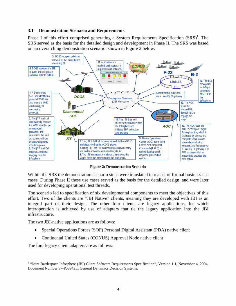
3.1 Demonstration Scenario and Requirements Phase I of this effort comprised generating a System Requirements Specification (SRS)1. The SRS served as the basis for the detailed design and development in Phase II. The SRS was based on an overarching demonstration scenario, shown in Figure 2 below.
AOC
JTF
DCGS Enterprise Services(JBI Mercury)
Approval Application GUI
CDR JAG TGT S2 S3
Engage Cancel
Approval Application GUI
CDR JAG TGT S2 S3
Engage Cancel LinkLink--1616
FF--2222FF--2222 BB--22BB--22
DismountedSOF
1. A Dismounted SOF unit identifies a potential WMD site and injects a WMD alert using JBI messaging protocols.
2. The JTF Intel cell automatically receives the WMD alert (as per commander’s guidance) and determines the alert associates with an established priority monitoring area.3. The JTF Intel Cell requests additional imagery from the Infosphere.
6. The JTF Intel Cell receives Video Intel from DCGS and views the Intel in a COTS player. 7. Using JTT, the JTF confirms it is a known enemy site and is not on the restricted targets list.8. The JTF nominates the site as a time-sensitive target, posts the information to the Infosphere.
9. The Air Operations Center (AOC) at the Joint Forces Air Component Command (JFACC) is tasked develop quick-response prosecution options.
10. The AOC uses the ADOCS Weapon Target Pairing function, which is facilitated by access to a complete set of aircraft status data including weapons and fuel state via a Link-16/JBI gateway. The AOC assesses that an inbound B2 provides the best option.
4. DCGS receives the ISR request and assigns an available UAV to fulfill it.
CONUSAgencies
11. Authorities are notified, and approval is requested and obtained.
12. The AOC tasks the inbound B2, through JBI, to engage the target.
13. The B-2 crew posts an inflight-generated MISREP to the Infosphere.
14. The JTF Intel cell receives the MISREP from the Infosphere and initiates BDA collection and analysis
5. DCGS Adapter publishes relevant DCGS surveillance data into JBI.
Aircraft status published via a Link-16/JBI gateway
5. DCGS Adapter publishes relevant DCGS surveillance data into JBI.
Aircraft status published via a Link-16/JBI gateway
Figure 2: Demonstration Scenario
Within the SRS the demonstration scenario steps were translated into a set of formal business use cases. During Phase II these use cases served as the basis for the detailed design, and were later used for developing operational test threads.
The scenario led to specification of six developmental components to meet the objectives of this effort. Two of the clients are “JBI Native” clients, meaning they are developed with JBI as an integral part of their design. The other four clients are legacy applications, for which interoperation is achieved by use of adapters that tie the legacy application into the JBI infrastructure.
The two JBI-native applications are as follows:
• Special Operations Forces (SOF) Personal Digital Assistant (PDA) native client
• Continental United States (CONUS) Approval Node native client
The four legacy client adapters are as follows:
1 “Joint Battlespace Infosphere (JBI) Client Software Requirements Specification”, Version 1.1, November 4, 2004, Document Number 97-P53942L, General Dynamics Decision Systems.
4

• JBI/Distributed Common Ground Station (DCGS) adapter
• JBI/Marine Joint Task Force (JTF) Intelligence Cell adapter
• JBI/Air Operations Center (AOC) adapter
• JBI/Link-16 adapter
Each of the six components implement a front-end interface to JBI that is CAPI-compliant. The four legacy adapters each have an automated back-end interface to their corresponding legacy system that is compliant with that system’s interface requirements, without modification to that system’s software baseline. The two JBI-native applications embed all functionality required to satisfy their roles in the demonstration scenario.
Figure 3 below shows these six components within the high level system architecture. The shaded boxes represent new components designed in this effort, and the un-shaded boxes represent existing components.
DCGSSOF PDA Marine JTF Intel Cell AOCCONUS Approval
Node Link16 Gateway
JBI
JBI/DCGS Adapter
JBI/Marine JTF Intel Cell Adapter
JBI/AOC Adapter
CONUS Approval JBI Native Client
Link16 AdapterSOF PDA JBI Native Client
MDF C2PC ADOCS Link 16 Network
ETS
Figure 3: High-Level System Architecture
The SRS also captured:
• Information flows for each use case
• User interfaces, legacy or new, that would play a part in the scenario
• Information Object identification and requirements
• Design Details (per adapter/client)
o Detailed adapter architecture
o Adapter/client level use cases
o UML sequence diagrams showing information flow within the adapter
5

3.2 Detailed Design The detailed design was captured within a Software Design Description (SDD)2 that was delivered on March 23, 2005. AFRL reviewed the SDD—the team jointly decided that a subsequent formal review event was unnecessary.
The SDD was built on the previously delivered SRS. The detailed SDD added the following new material:
• Adapter State Diagrams
• Information Object Schemas
• Information Mappings
The tasks performed to generate these elements are described in subsections 3.2.1 through 3.2.3 below.
3.2.1 Define Adapter State Diagrams This task generated a representation of the varying states that can be reached within each adapter/client.
Output: Definition of Unified Modeling Language (UML) State Diagrams for each adapter/client.
3.2.2 Define Information Object Schemas This task generated the 9 XML Metadata Schemas that were be used to build the JBI Information Objects (IO).
Output: The schemas are listed, and are also provided as XSD files separate from the SDD.
3.2.3 Define Information Mappings This task defined information mappings between organic adapter data and each IO the adapter publishes or subscribes to.
Output: For each adapter details are provided as to how the information in the IO XML documents is mapped to and from the legacy (or native) data sets.
3.3 Implementation Implementation comprises coding, unit-testing, system testing, integration, and integration testing. GDC4S developed the AOC/ADOCS and JTF/C2PC adapters. Sensis Corporation developed the CONUS Approval Node and SOF/PDA native clients, the Link-16 Adapter, and the DCGS Adapter.
During code development, GDC4S and Sensis utilized the inherently loosely coupled architecture of JBI to perform the majority of development within their own facilities. Due to the 2 “Joint Battlespace Infosphere (JBI) Client Software Design Description”, March 23, 2005, CDRL B002-002, Revision A, General Dynamics.
6

Infosphere architecture, each team was able to quickly develop the test drivers and harnesses needed to take the place of components that would not be available until full integration. The risks generally associated with integration of disparate components were mitigated by data-collecting and sharing Information Objects via email prior to site integration.
3.3.1 ADOCS Adapter The overall ADOCS adapter architecture is shown in Figure 4 below. The Universal Information eXchange (UIX) was an existing GDC4S software asset that already was able to perform the processing necessary to accomplish much of the adapter’s ADOCS requirements.
ADOCS
Figure 4: ADOCS Adapter Architecture
UIX communicates with ADOCS in four distinct ways:
1. Retrieve ADOCS Time Critical Target (TCT) Data – To get TCT data UIX reads the ADOCS TCT file directly. Sometimes the adapter synchronously queries for the data through UIX. Other times, such as when reacting to the user making TCT changes though the ADOCS user interface, the adapter uses UIX’s internal asynchronous publish/subscribe capability to receive the new data automatically.
2. Update ADOCS TCT Data – When the C2PC adapter publishes a TCT Designation IO or the CONUS Approval Node web application publishes a change via a TCT Coordination IO the ADOCS adapter executes that transaction against the ADOCS TCT repository. It does this by pretending to be a separate ASRV (the ADOCS communications server program) node on the ADOCS network, and sending a properly formatted message to the
JBI
AOC Adapter
UIX
TCT Data
ATO Data
Tracks
Existing Software
7

real ASRV. The adapter also updates TCT records when it receives Engagement Status and Mission Report IOs.
3. Create/Update ADOCS Tracks – To create/update tracks in ADOCS the adapter transforms incoming Air Status Information Objects into standard OTH Gold messages and places them as a files in the ADOCS in-box directory.
4. Query The ATO – The adapter uses information from the ATO to perform engagement tasking processing.
The ADOCS adapter reacts to stimulus shown in Table 2 below. (The Discussion items in this table reference the numbered items in section 3.3.1 above.)
Table 2 ADOCS Adapter Stimulus
Stimulus Source Discussion Air Status Information Objects
Link-16 Adapter
As the Link-16 adapter generates air track information, tracks are created/updated in ADOCS as described in number 3 above. To determine whether to update an existing track or create a new one the adapter maintains an internal list of track-ids from the IOs mapped against internal ADOCS track-ids. The list is not persisted so if the adapter re-starts it creates duplicate tracks, but ADOCS deletes tracks that are not updated frequently.
TCT Designation Information Objects
C2PC Adapter When the user at C2PC indicates that a target is a TCT, the ADOCS adapter creates a new TCT record using the technique described in number 2 above.
ADOCS User Modifies a TCT
ADOCS User When the ADOCS user makes a change to a TCT record (UIX publish/subscribe processing described in number 1 above) the adapter always publishes a corresponding TCT Coordination IO so the CONUS web application will have the new data. In addition, under the right circumstances, the adapter may also publish a TCT Engagement Tasking IO, which causes the designated aircraft to engage the target. For this to occur:
• The TCT MSN (Mission) status must be set to either yellow or green, and:
• An air mission must have been assigned to that TCT (using either direct selection or WTP) that corresponds to an active air track. This correlation is performed by mapping the air mission identifier to the ATO (see number 4 above), and then mapping the ATO mission IFF code to the IFF code of the air track from Link-16.
TCT Coordination Information Objects
CONUS Approval Web Application
When the CONUS Approval Web Application user changes the approval status of a TCT it publishes a TCT Coordination IO. When the ADOCS adapter receives this it executes the corresponding change to the ADOCS TCT repository (see number 2 above). After this transaction the adapter queries ADOCS for the TCT record (see number 1 above), and then republishes a complete TCT Coordination IO. The adapter does this so that any changes ADOCS made resulting from the discrete approval status change are made available to subscribers.
Engagement Status and Mission Report Information Objects
Link-16 Adapter
As updated mission status comes in the ADOCS adapter updates the corresponding TCT with the information (see number 2 above).
8

3.3.2 C2PC Adapter The overall C2PC Adapter architecture is shown in Figure 5, below. The C2PC Java Bindings (CJB), provided with the C2PC development kit, are utilized by the adapter to communicate with the native COM interfaces exposed to C2PC developers.
C2PC 6.0.2
CJB (Java COM)
JTF Adapter
JBI
Existing Software
Figure 5: C2PC Adapter Architecture
C2PC’s developer interfaces are separated into distinct packages based on functional areas. The C2PC adapter communicates with C2PC (via CJB) using the following Application Programming Interfaces (APIs):
• C2PC Alert Services 6.1.0: This package allows the adapter to provide audible, categorized, text based alert messages to the C2PC operator.
• C2PC Overlays 6.1.0: This package allows the adapter to recognize that the operator has modified overlay graphics on the C2PC map display. It also allows the adapter to make modifications to these graphics.
• C2PC TMS 6.1.0: This package allows the adapter to submit new and updated track reports to the C2PC track management system. It also allows the adapter to recognize when certain track characteristics have been changed (for example, a user’s interaction may result in a track change).
The C2PC adapter responds to the stimulus shown in Table 3, below. While some of the sources may refer to other Sensor to Shooter adapters, note that the C2PC adapter is in no way dependent on specific, other adapters—the sources listed simply describe the source that was relevant during the Sensor to Shooter demonstration.
9

Table 3 C2PC Adapter Stimulus
Stimulus Source Discussion Target Alert Information Object (IO)
PDA Adapter
A ground track is generated and submitted to C2PC via the TMS Service. The adapter generates a unique identifier for the new ground track, which may be referenced later in ISR requests, target nominations, and engagement statuses. Finally, a corresponding C2PC alert is generated and submitted to C2PC via the Alert Service.
ISR Request C2PC User
The operator creates a rectangular or circular overlay graphic, and includes “ISR” in the name of the graphic. Once “saved” on the C2PC map, the adapter will recognize this (via the Overlay Service) and respond by creating a corresponding ISR request IO and publishing this to the Infosphere. An internal mapping to a corresponding C2PC track is also made, if the user has provided this information on the overlay graphic. Finally, if the C2PC client supports it, the adapter will apply a transparent yellow fill to the overlay graphic to provide the operator with feedback on the ISR request (to the best of our knowledge, the recoloring fails to work on Windows 2000 installations of C2PC).
ISR Product IO DCGS Adapter
The adapter publishes a set of operator alerts, via the Alert Service. One alert notifies the user that an ISR product has been received. The other contains the path to the ISR product, if a payload has been included in the publication. If enough information is available in the ISR response, the adapter updates the corresponding graphic overlay (via the Overlay Service) to indicate that a response to the ISR request has arrived.
Target Nomination
C2PC User
The operator nominates a target track by enabling the Time Critical Target (TCT) checkbox on the track’s properties dialog. The adapter recognizes this change, via notification from the TMS Service. The adapter publishes a TCT Designation IO to the Infosphere.
Aircraft Status IO
Link-16 Adapter
For each new aircraft encountered in an aircraft status IO, the adapter will create a corresponding track in C2PC, via the TMS Service. A mapping is maintained between aircraft IDs originating from the Infosphere and track IDs maintained within C2PC. As additional aircraft status messages arrive for a previously encountered aircraft identifier, the adapter adds track “reports” to the corresponding C2PC track. Each report represents chronologically updated information on the particular track (the new location, heading, speed, etc.).
Engagement Status IO
Link-16 Adapter
If the status references known ground tracks, then these tracks are updated, via the TMS Service, to reflect the blue force weapon and remark information, and the enemy objective remarks.
Mission Status IO
Link-16 Adapter
The mission status information is formatted into a human readable message, and submitted to the user via the Alerts Service.
3.3.3 Link16 Adapter The Link16 Adapter was responsible for implementing a minimal Command and Control JTIDS Unit (C2 JU) on the Link16 network. For this demonstration, the required capabilities included:
• Allow JBI Participants to assign Air-To-Ground missions to controlled Link16 aircraft • Report Engagement status of controlled aircraft to both link16 and JBI • Report position, platform, and engagement status of Link16 controlled aircraft to the JBI. • Implement minimum Link16 C2 Unit participation requirements • Report Link16 J28.2 Messages to the JBI
10

To facilitate integration into Link16 and to simulate the Link16 network for this demonstration, the JBOSS software suite provided by Tactical Communications Group (TCG) under a developer’s license was selected. This software suite provides a Link16 simulator and a convenient Link16 Application Programming Interface (API) for communicating on Link16. Behind the API, the Tactical Communications Manager (TCM) software component of JBOSS manages most of Link16’s low-level message formats, timing and transmission protocols, along with Report Responsibility (R2) and Track Number (TN) generation.
The Link16 simulator packaged with JBOSS allows users to create and run scenarios. These scenarios consist of user defined air, space, land, and maritime elements. When the scenario is run, the simulator generates the appropriate Link16 messages onto the Link16 interface. For this demonstration, the link16 interface was stubbed so that the link16 traffic was fed into the Link16 Adapter. This setup allows for a real Link16 network to be easily swapped in place of the simulator. For this demonstration, a Link16 scenario was generated to match the aircraft defined in the Air Tasking Order (ATO) used in ADOCS.
Link16MessageProcessor
B-2 Simulator
EnvironmentSimulator
HostAdapter
HostAdapter
Link16MessageProcessor
LINK 16 SIT Display
JBI
LINK16 Simulation
JBI/LINK16 Adapter
TCM Software Suite
Developed
CGIS
LINK16 Stub
Figure 6: Link16 Simulation Environment Configuration
As shown in Figure 6 above, the Link16 Adapter was designed to run as a module within the C4ISR Gateway Interface System (CGIS). CGIS provides a software architecture designed to facilitate the integration of Legacy systems into JBI. It does so by separating Legacy System communication from the data processing of the Legacy System’s data. This separation is realized through Client Interface Modules (CIM) and Processing Agents (PA). The Link16 CIM manages all the communication with the TCM Host Adapter and provides the Link16 PA with descriptive, XML-based documents containing the information received from the Host Adapter. The Link16 PA processes the normalized information and communicates with the JBI.
The Link16 PA consists of subordinate PAs that perform specific C2 Unit responsibilities. This design allowed Sensis to implement the C2 capabilities required for this demonstration while
11
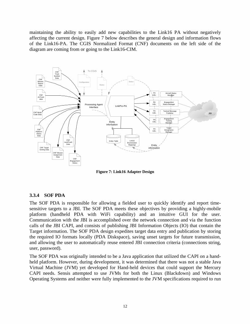
maintaining the ability to easily add new capabilities to the Link16 PA without negatively affecting the current design. Figure 7 below describes the general design and information flows of the Link16-PA. The CGIS Normalized Format (CNF) documents on the left side of the diagram are coming from or going to the Link16-CIM.
CNFAirTrack
data
StatusConfiguration
CNFPlatformStatusData
CNF ModeCode Data
CNFLandTrack
Data
CNFMissionReportData
CNF TargetSorting Data
CNF MissionAssignment
Data
Processing AgentInterface LinkPro-PA
Entity Table Link16Enumeration
Mappings Entityinformation
To CGIS
Aircraft StatusManager
EngagementStatus Manager
EngagementTaskingManager
TargetDesignation
Manager
PAIntfc.
PAIntfc.
PAIntfc.
PAIntfc.
Tactical MessagePublisher
PAIntfc.
CNFTrack
NumberData
CNFEngagement
Status
JBI
Status
Entityinformation
Figure 7: Link16 Adapter Design
3.3.4 SOF PDA The SOF PDA is responsible for allowing a fielded user to quickly identify and report time-sensitive targets to a JBI. The SOF PDA meets these objectives by providing a highly-mobile platform (handheld PDA with WiFi capability) and an intuitive GUI for the user. Communication with the JBI is accomplished over the network connection and via the function calls of the JBI CAPI, and consists of publishing JBI Information Objects (IO) that contain the Target information. The SOF PDA design expedites target data entry and publication by storing the required IO formats locally (PDA Diskspace), saving unset targets for future transmission, and allowing the user to automatically reuse entered JBI connection criteria (connections string, user, password).
The SOF PDA was originally intended to be a Java application that utilized the CAPI on a hand-held platform. However, during development, it was determined that there was not a stable Java Virtual Machine (JVM) yet developed for Hand-held devices that could support the Mercury CAPI needs. Sensis attempted to use JVMs for both the Linux (Blackdown) and Windows Operating Systems and neither were fully implemented to the JVM specifications required to run
12

the Mercury CAPI. Also, the size of the Mercury CAPI was much too large for most Hand-held devices. These circumstances led to the development of a SOF PDA application written in C# which took advantage of Microsoft’s .Net framework and the already developed Mercury web-CAPI. This solution architecture is shown in Figure 8 below.
JBIWeb
ServicesInterface
.Net Framework
Native ClientGUI
Figure 8: SOF PDA Design
Originally, it was intended that the SOF PDA GUI would be directly tied to the XML of the Target Reports it was generating. The rationale behind this decision was that an XML schema should be designed around data representation, and the schema for a Target Report should reflect the most intuitive way in which a human operator would understand it. However, during development, a second Information Engineering paradigm arose; to encourage reusability, and to best reflect its name, a Target Report Information Object should be capable of reporting any target (air, land, maritime, space). But the options available to report any type of target would be too complicated and would overwhelm a user, especially in the high-stress environment that can be imagined in a combat environment. So that the user would only be presented with the information and options most critical to his situation (in this case, reporting land targets—see Figure 9 below), the final design of the SOF PDA GUI consists of an XML document that describes that critical information. The SOF PDA software performs the mapping from the GUI data to the Target Alert IO in the background.
13

Figure 9: SOF PDA GUI
3.3.5 CONUS Node In the demonstration scenario, the CONUS Approval Node is responsible for authorizing Time-Critical-Target (TCT) Engagements. As a participant in the TCT workflow, this client displays the current state of TCTs in JBI, and allows the operator to register approval or otherwise of TCT engagements. The CONUS Node mirrors the TCT Approval GUI within ADOCS—its development for this program demonstrates the ease in which functionality currently only available to users with full installation of ADOCS could be made available through a JBI based web application.
14
Apache/Tomcat
JBI
CONUS Servlet
IOR
Figure 10: CONUS Node Design
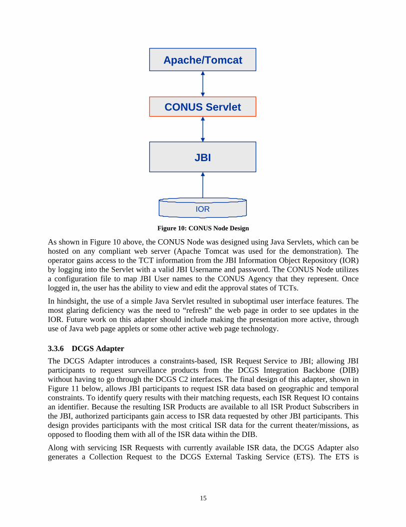
As shown in Figure 10 above, the CONUS Node was designed using Java Servlets, which can be hosted on any compliant web server (Apache Tomcat was used for the demonstration). The operator gains access to the TCT information from the JBI Information Object Repository (IOR) by logging into the Servlet with a valid JBI Username and password. The CONUS Node utilizes a configuration file to map JBI User names to the CONUS Agency that they represent. Once logged in, the user has the ability to view and edit the approval states of TCTs.
In hindsight, the use of a simple Java Servlet resulted in suboptimal user interface features. The most glaring deficiency was the need to “refresh” the web page in order to see updates in the IOR. Future work on this adapter should include making the presentation more active, through use of Java web page applets or some other active web page technology.
3.3.6 DCGS Adapter The DCGS Adapter introduces a constraints-based, ISR Request Service to JBI; allowing JBI participants to request surveillance products from the DCGS Integration Backbone (DIB) without having to go through the DCGS C2 interfaces. The final design of this adapter, shown in Figure 11 below, allows JBI participants to request ISR data based on geographic and temporal constraints. To identify query results with their matching requests, each ISR Request IO contains an identifier. Because the resulting ISR Products are available to all ISR Product Subscribers in the JBI, authorized participants gain access to ISR data requested by other JBI participants. This design provides participants with the most critical ISR data for the current theater/missions, as opposed to flooding them with all of the ISR data within the DIB.
Along with servicing ISR Requests with currently available ISR data, the DCGS Adapter also generates a Collection Request to the DCGS External Tasking Service (ETS). The ETS is
15

responsible for handling requests for new ISR, and dictates ISR collection missions to fielded sensors, in particular, the Predator Unmanned Aerial Vehicles (UAV).
For demonstration purposes the normal ETS tasking and approval process is simulated by the ETS Responder application (shown in Figure 11 below). This application sits behind ETS and the Metadata Framework (MDF), automatically providing immediate NITF imagery responses to ETS collection requests.
JBI DCGS Adapter
ETSResponder
JBI CAPI EJB, JMS
ETS
MDF
DCGS 10.2
ISR Products
Figure 11: DCGS Adapter Design
3.4 Final Demonstration The final demonstration occurred within GDC4S facilities in Scottsdale, AZ on August 31, 2005. Results of the final demonstration are discussed in Section 4.1 below. Before the actual event a Demonstration Plan3 was delivered on August 17, 2005. The original project plan called for the demonstration to occur approximately one month earlier, but this was changed, mostly due to delays related to coordinating availability and support for DCGS.
Complete system integration occurred prior to the final demonstration. To facilitate this the Sensis developers and the computers on which their adapters and development environments resided were given access to the GDC4S network.
4 Results and Discussion The ultimate objective of this effort was to fulfill the requirements of the scenario with a live demonstration, and to use that event to facilitate collaboration, exploration and discussion. This section summarizes the final demonstration.
3 “Software Demonstration Plan For The Joint Battlespace Infosphere (JBI) Client Adapter”, CLIN 0004 Data Item No. B003, August 17, 2005, General Dynamics Inc.
16
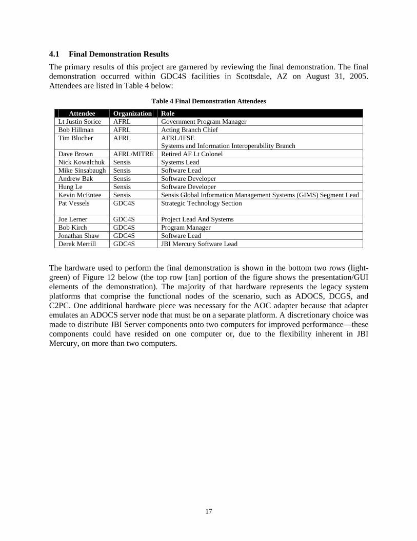
4.1 Final Demonstration Results The primary results of this project are garnered by reviewing the final demonstration. The final demonstration occurred within GDC4S facilities in Scottsdale, AZ on August 31, 2005. Attendees are listed in Table 4 below:
Table 4 Final Demonstration Attendees
Attendee Organization Role Lt Justin Sorice AFRL Government Program Manager Bob Hillman AFRL Acting Branch Chief Tim Blocher AFRL AFRL/IFSE
Systems and Information Interoperability Branch Dave Brown AFRL/MITRE Retired AF Lt Colonel Nick Kowalchuk Sensis Systems Lead Mike Sinsabaugh Sensis Software Lead Andrew Bak Sensis Software Developer Hung Le Sensis Software Developer Kevin McEntee Sensis Sensis Global Information Management Systems (GIMS) Segment Lead Pat Vessels
GDC4S Strategic Technology Section
Joe Lerner GDC4S Project Lead And Systems Bob Kirch GDC4S Program Manager Jonathan Shaw GDC4S Software Lead Derek Merrill GDC4S JBI Mercury Software Lead
The hardware used to perform the final demonstration is shown in the bottom two rows (light-green) of Figure 12 below (the top row [tan] portion of the figure shows the presentation/GUI elements of the demonstration). The majority of that hardware represents the legacy system platforms that comprise the functional nodes of the scenario, such as ADOCS, DCGS, and C2PC. One additional hardware piece was necessary for the AOC adapter because that adapter emulates an ADOCS server node that must be on a separate platform. A discretionary choice was made to distribute JBI Server components onto two computers for improved performance—these components could have resided on one computer or, due to the flexibility inherent in JBI Mercury, on more than two computers.
17

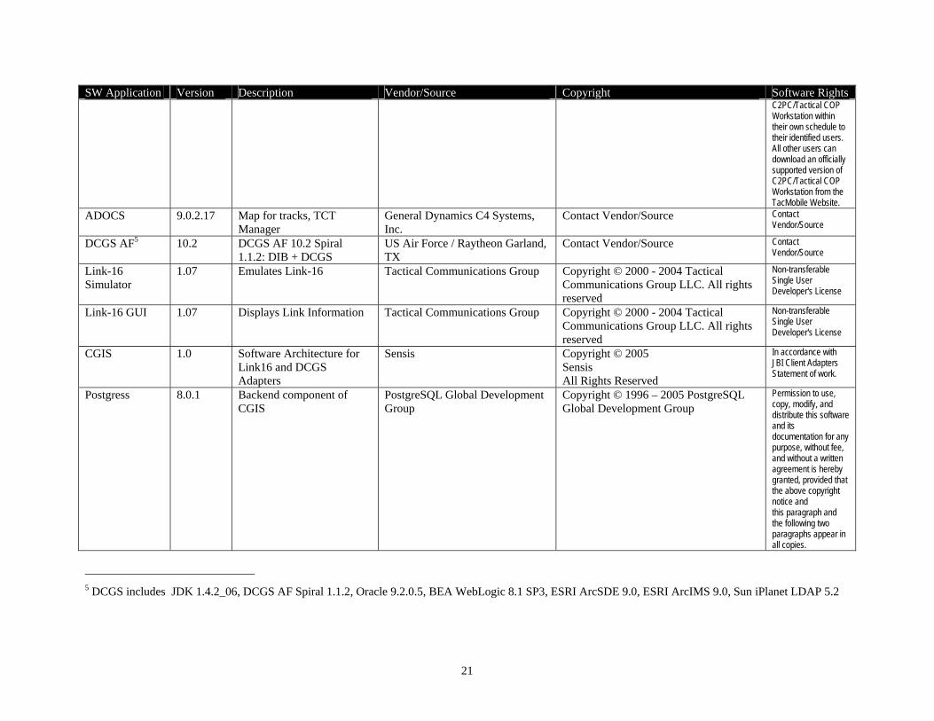
Table 5 below (Software Parts/License List) contains vendor, licensing, and software rights information for this initiative’s non-developed COTS software components. All software products are governed by their respective stated software license agreements. The following software products have software license restrictions limiting use:
The software used to perform the final demonstration is shown in Figure 13 below (when reading this document online the figure can be opened as an Excel worksheet). This table was used extensively during integration and for planning the demonstration. Although there are many other configurations that could also work, it is useful to document this configuration as a baseline.
• DCGS – DCGS includes COTS packages such as Oracle 9.2.0.5, BEA WebLogic 8.1, ESRI ArcSDE 9.0, ESRI ArcIMS 9.0, and Sun iPlanet LDAP 5.2—license restrictions may vary depending on the installation.
• Fiorano MQ™, TigerLogic®, and MySQL in JBI Mercury – As part of JBI Mercury these packages have no license costs during a 45 day evaluation period. After that period, for fielded use, their usage reverts to each vendor’s license restrictions.
• TCG Link-16 Simulator and GUI – This was purchased by Sensis under pricing specifically to develop this demonstration.
Figure 12: Demonstration Hardware
18

(9 computers - 11 pieces) Node Name SOF JTF JBI 1 JBI 2 AOCADOCSAdapter
DCGSServer
Link-16Server
Link-16Adapter
NetworkHub
WirelessRouter
Platform TypeAxiomX5PocketPC
2003PC
WinXPPC
Win2KPC
Win2KPC
Win2KPC
Win2K
Sun Blade 2000,
Solaris 2.8PC Laptop
WinXPPC Laptop
WinXP
1Gb Switch12 port
WirelessEthernet
Who Brings Sensis GD GD GD GD GD GD Sensis Sensis GD GDIP Address (192.168.40.*) 249 25 55 56 247 253 108 250 251
Host Name PDA B45DQ71 CNJBP31 BNJBP31 GK1K231 91RBP31 AFDCGSSVR0 huggybare starsky
SW Application
COTS/GOTS
($: cost may
apply)
GUIServer
AdapterNative Description
JRE 1.4.2_08 C Java 1.4.2_08 run-time environment X X X X XJDK 1.4.2_08 C Java 1.4.2_08 development kit XJDK 1.4.2_06 C Java 1.4.2_06 development kit (must be _06) XMicrosoft .NET Runtime C Microsoft .NET Compact Framework XJBI Security Master G S JBI Identity Server XJBI Mercury MDR G S JBI Mercury MDR XJBI Mercury Broker G S JBI Mercury Broker XJBI Mercury IOR G S JBI Mercury IOR XJBI Mercury Fiorano MQ G S JMS XJBI Mercury Tiger Logic G S Tiger Logic XML Repository XJBI Mercury Web CAPI G S JBI Mercury Web Services XJBI Mercury Client G For using CAPI X X X XApache Jakarta Tomcat 5.0.28 C S App. Server for CONUS, Web CAPI, and JBIeagle X XJBI Mercury JBIeagle G S JBI Mercury Search tool XSOF Client (JBI Native) N Submits WMD alert from PDA XC2PC 6.1 Patch 2 G G GUI, map for tracks, ISR requests XJBI JTF (C2PC) Adapter A JBI Adapter for JTF/C2PC XADOCS ASRV 9.0.2.17 G S ADOCS Communications Server XADOCS GUI Client 9.0.2.17 G G Map for tracks, TCT Manager XJBI AOC Adapter A JBI Adapter for AOC/ADOCS XCONUS Web Application N Server-side CONUS web application XCONUS Browser App. #1 C G Standard browser to approve XCONUS Browser App. #2 C G Standard browser to approve XDCGS portal via Browser C G Standard browser to see portal and map displays XJBI DCGS Adapter A JBI Adapter for DCGS XDCGS AF Spiral 1.1.2 G S DCGS AF 10.2 Spiral 1.1.2: DIB + DCGS XOracle 9.2.0.5 C $ S (using DIB/DCGS install media) XBEA WebLogic 8.1 SP3 C $ S (using DIB/DCGS install media) XESRI ArcSDE 9.0 C $ S for map display (not absolutely required) XESRI ArcIMS 9.0 C $ S for map display (not absolutely required) XSun iPlanet LDAP 5.2 C S Sun Java System Directory Server XDCGS ETS Software G S Part of DCGS Core XETS Responder S DCGS Back-End Request Response Sim XLink-16 Server G $ S Emulates Link-16 XLink-16 GUI G $ G Displays Link Information XCGIS Software for Link-16 and DCGS Adapters XPostgress 8.0.1 Backend database for CGIS XJBI Link-16 Adapter A JBI Adapter for Link-16 X
Figure 13: Demonstration Software Configuration
19

Table 5 Software Parts/License List
SW Application Version Description Vendor/Source Copyright Software Rights JRE 1.4.2_08 1.4.2_08 Java 1.4.2_08 run-time
environment Sun Microsystems Copyright 1994-2004 Sun Microsystems,
Inc. Commercial Computer Software - In accordance with commercial license agreement.
JDK 1.4.2_08 1.4.2_08 Java 1.4.2_08 development kit
Sun Microsystems Copyright 1994-2004 Sun Microsystems, Inc.
Commercial Computer Software - In accordance with commercial license agreement.
Microsoft .NET Runtime
1.1 Microsoft .NET Compact Framework
Microsoft Corporation ©2005 Microsoft Corporation. All rights reserved.
Commercial Computer Software - In accordance with commercial license agreement.
JBI Mercury4 1.0 JBI Core service architecture
General Dynamics C4 Systems, Inc.
Copyright © 2005 General Dynamics All Rights Reserved
Commercial Computer Software / Restricted Rights - In accordance with commercial license agreement.
Apache Jakarta Tomcat
5.0.28 App. Server for CONUS, Web CAPI, and JBIeagle
Apache Software Foundation Copyright © 2000-2005 The Apache Software Foundation. All rights reserved.
In accordance with Apache License Version 2.0, January 2004
C2PC 6.1.0Patch 2
GUI, map for tracks, ISR requests
USMC - C2PC Project Office - Marine Corps Systems Command Space and Naval Warfare Systems Center C4I Mobile Systems Division
©2005 Copyright, Northrop Grumman Corporation. All rights reserved.
There are no restrictions on the distribution of C2PC/Tactical COP Workstation to US citizens and companies within the United States. C2PC is subject to arms export controls to foreign nationals and U.S citizens in foreign countries. Marine Corps systems of record shall distribute
4 JBI includes Fiorano MQ™, Raining Data TigerLogic® XDMS. No license cost for 45 day evaluation. Consult vendor for license cost information for fielded use of Fiorano MQ™, TigerLogic® and delivering MySQL.
20
21
plication Version Description Vendor/Source Copyright Software Rights
SW ApC2PC/Tactical COP Workstation within their own schedule to their identified users. All other users can download an officially supported version of C2PC/Tactical COP Workstation from the TacMobile Website.
ADOCS 9.0.2.17 Map for tracks, TCT Manager
General Dynamics C4 Systems, Inc.
Contact Vendor/Source Contact Vendor/Source
DCGS AF5 10.2 DCGS AF 10.2 Spiral 1.1.2: DIB + DCGS
US Air Force / Raytheon Garland, TX
Contact Vendor/Source Contact Vendor/Source
Link-16 Simulator
1.07 Emulates Link-16 Tactical Communications Group Copyright © 2000 - 2004 Tactical Communications Group LLC. All rights reserved
Non-transferable Single User Developer's License
Link-16 GUI 1.07 Displays Link Information Tactical Communications Group Copyright © 2000 - 2004 Tactical Communications Group LLC. All rights reserved
Non-transferable Single User Developer's License
CGIS 1.0 Software Architecture for Link16 and DCGS Adapters
Sensis Copyright © 2005 Sensis All Rights Reserved
In accordance with JBI Client Adapters Statement of work.
Postgress 8.0.1 Backend component ofCGIS
PostgreSQL Global Development Group
Copyright © 1996 – 2005 PostgreSQL Global Development Group
Permission to use, copy, modify, and distribute this software and its documentation for any purpose, without fee, and without a written agreement is hereby granted, provided that the above copyright notice and this paragraph and the following two paragraphs appear in all copies.
5 DCGS includes JDK 1.4.2_06, DCGS AF Spiral 1.1.2, Oracle 9.2.0.5, BEA WebLogic 8.1 SP3, ESRI ArcSDE 9.0, ESRI ArcIMS 9.0, Sun iPlanet LDAP 5.2

The final demonstration was held in the GDC4S Demonstration Room (H2604), which is specifically designed to facilitate the demonstration of multi-system integration efforts such as this project. As shown in Figure 14 below, this room is equipped with an impressive array of presentation assets, along with state-of-the-art controllers. These were used during the demonstration to effectively provide full visibility into the scenario content, human/machine interaction, and other demonstration mechanics.
Projector #2 Projector #1
Plasma Display #3
Plasma Display #2
Plasma Display #4
Plasma Display #1
Figure 14: Demonstration Presentation
A top-level overview of the scenario steps is shown in Table 6 below. A more complete and detailed list of the scenario steps can be found in the Software Demonstration Plan3 (page 16).
Table 6 Scenario Steps
Action Results 1. Initiate Link-16 Simulations (TCG and custom
aircraft simulation) • Air tracks displayed on ADOCS and C2PC • Aircraft platform information, such as weapon stores
and remaining fuel, is updated over time 2. Enter target into PDA • Target displayed on C2PC map and as alert 3. Create ISR Rectangle Around Target on C2PC
and save overlay • ISR Rectangle on C2PC changes color to yellow • ISR requests and, shortly thereafter, ISR product lists
each grow by one on DCGS/ETS. • ISR Rectangle on C2PC changes color to green and
C2PC alert indicates where on local computer returned ISR NITF image is stored
4. Add NITF image as C2PC display • NITF image displayed on C2PC 5. Check TCT box on target in C2PC and save • New TCT created in ADOCS AOC Target manager,
and in CONUS web application • New target created in Link-16
6. Modify approval columns in ADOCS to yellow, and refresh CONUS web application
• Approval columns on CONUS web applications match ADOCS
7. Update approval from yellow to green using CONUS web application
• Corresponding column in ADOCS updated to green
8. Using ADOCS, select the ATO mission that corresponds to the aircraft being flown by the aircraft simulator, and update the MSN column to green
• Corresponding aircraft turns towards and begins engagement of the target
• Status of target on ADOCS shows updated mission status information
• Upon expending munitions to neutralize the target, the engaging aircraft’s weapons stores are dynamically updated, confirming the release of munitions.
22
During the demonstration there was one deficiency which caused the CONUS web application to not display the most current TCT information. This was caused by a known bug in the IOR which has been fixed in JBI Mercury 1.1.
4.2 Project Metrics This section discusses a set of qualitative and quantitative factors relevant to the value-added of our demonstration system in comparison with current capabilities. The intent is to provide a set of compelling criteria to justify the advanced development of JBI adapter components as a framework for integration of near-term operational systems, versus directly-coupled interfaces. The following account concerning a system that depended on directly-coupled interfaces may help set the tone:
A few years ago an ambitious software system was developed that provided an optimized many-on-many Weapon Target Paring (WTP) capability. This system’s WTP algorithm required many inputs, such as multiple days’ air mission plans and updates in the ATO, current correlated aircraft and air mission status (position, fuel status, weapon status, activity), threat locations and status, current overall theater weapon availability and usage priorities, commander’s guidance, information on Integrated Air Defense Systems (IADS), Battlespace Geometries (e.g., FSCM’s, no-fly zones), target no-strike lists, etc. To obtain these inputs discrete point-to-point interfaces were developed to many different systems, such as TBMCS, AFATDS, ASAS, GCCS, MIDB, JTT, TDBM, and JMEMS.
Although this system’s innate WTP capability was robust and of great value to the warfighter, the program was saddled with frequent and costly technical challenges in developing and maintaining the requisite interfaces. This was due to the variability of the interfaces across different theater installations, and the volatility of the interfaces over time. Had there been an Infosphere, with one simple interface to obtain the necessary enterprise information in standardized formats, this particular investment, and others like it, may have provided a significantly higher return.
An important benefit supporting the asynchronous workflow needed during an ad-hoc targeting cycle is derived from the fact that each JBI client adapter has immediate access to a common air and ground picture (aircraft location along with fuel and weapon status, and ground target location). The dynamic sharing of this information enables a greater level of situational awareness in the system each client adapter is connected to. This helps achieve a greater degree of process integration across all the client systems, in support of the overall ad-hoc ATO planning and execution workflow. In particular, the following tasks are supported:
• Planning
• Operations (Execution)
• Intelligence
• Approval Coordination
• Tasking
• Battle Damage Assessment
23

4.2.1 Qualitative Value-Added Factors: The following factors instinctively flow from an Infosphere approach:
• Improved Decision-Making through sharing of a common situational picture. (Air & Ground).
• Scalability as a function of resource requirements: Using an individual integration approach there are N x (N-1) individual connections necessary to directly connect all the participating applications in the system to each other. The Infosphere approach requires only N connections (to the server from each application).
• Software Re-use
4.2.2 Quantitative Value-Added Factors: The traffic and communication demands of all interacting components in this bounded demonstration system are well below the processing limits of the Client Adapters and the JBI Core Services Platform. As this initiative progresses from proof-of-concept to advanced development, the following metrics become more feasible to address with regard to the intended operational environment(s) in which the adapter components will be required to operate:
• Adapter performance under load - which deals with how many individual legacy clients and flows each adapter may be required to service in the intended operational system.
• Server performance under load - which deals with the simultaneous demands of all simultaneous publisher and subscriber sequences in the intended operational system.
• Development cost savings as number of participating adapter connections to a JBI increases. This factor addresses development cost as a function of the number of legacy systems that will be integrated with a JBI adapter, with the intent to verify that use of JBI adapters as a integration framework becomes more cost-effective as the number of systems integrated via an adapter increases.
5 Concluding Remarks The JBI client adapters developed in this effort integrate key aspects of existing C2, ISR, and tactical systems and networks to provide worldwide information visibility and situation awareness. The demonstration showcased the ability of a set of distributed adapters to transparently support the business processes required for dynamic target cycle coordination in a JBI. The adapters and legacy systems selected for the demonstration scenario in this project demonstrate integration of:
• Air Force Transformational Programs o AOC o DCGS-AF
• Enterprise Architectures o JBI o NCES
24

o DCGS Integration Backbone (DIB) • Tactical Systems
o ADOCS o C2PC
• Tactical Networks o Joint Tactical Information Distribution System (JTIDS - Link16 protocol)
Some specific capabilities provided by JBI that this demonstration helped validate are listed in Table 7 below:
Table 7 Infosphere Value Add
Value Add Discussion Intelligent Information Distribution
Both the C2PC and ADOCS Adapters shared a Common Air Picture (CAP) by simply subscribing to air track information objects. This architecture decouples the end users from the complicated hardware, software, and data requirements of the numerous external sensors previously needed. This allows each component to concentrate on its core responsibility, be it information analyzer or information provider.
Easier Development of Capabilities
The CONUS approval web page provides thin-client based coordination that is not available today. This is an ideal architecture for fast changing ADOCS TCT coordination and approval elements such as other services or coalition partners.
Universal Information Access
An Infosphere provides increased flexibility, sometimes allowing data to be used in previously unexpected ways. Immediate access to authorized information can be provided that may have been otherwise unavailable. Dependencies on complex legacy integration architectures are reduced, to the point where swapping key systems becomes more viable. Systems are more easily simulated, tested, and recorded. Archiving data provides the ability to examine information flows after the fact for analysis.
25
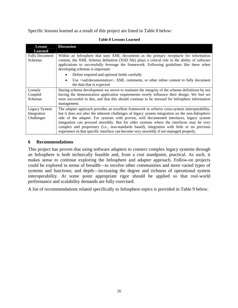
Specific lessons learned as a result of this project are listed in Table 8 below:
Table 8 Lessons Learned
Lesson Learned
Discussion
Fully Document Schemas
Within an Infosphere that uses XML documents as the primary receptacle for information content, the XML Schema definition (XSD file) plays a critical role in the ability of software applications to successfully leverage the framework. Following guidelines like these when developing schemas is important:
• Define required and optional fields carefully • Use <xsd:documentation>, XML comments, or other inline content to fully document
the data that is expected Loosely Coupled Schemas
During schema development we strove to maintain the integrity of the schema definitions by not having the demonstration application requirements overly influence their design. We feel we were successful in this, and that this should continue to be stressed for Infosphere information management.
Legacy System Integration Challenges
The adapter approach provides an excellent framework to achieve cross-system interoperability, but it does not alter the inherent challenges of legacy system integration on the non-Infosphere side of the adapter. For systems with proven, well documented interfaces, legacy system integration can proceed smoothly. But for older systems where the interfaces may be very complex and proprietary (i.e., non-standards based), integration with little or no previous experience in that specific interface can become very unwieldy if not managed properly.
6 Recommendations This project has proven that using software adapters to connect complex legacy systems through an Infosphere is both technically feasible and, from a cost standpoint, practical. As such, it makes sense to continue exploring the Infosphere and adapter approach. Follow-on projects could be explored in terms of breadth—to involve other communities and more varied types of systems and functions; and depth—increasing the degree and richness of operational system interoperability. At some point appropriate rigor should be applied so that real-world performance and scalability demands are fully exercised.
A list of recommendations related specifically to Infosphere topics is provided in Table 9 below.
26

Table 9 Infosphere Recommendations
Recommendation Discussion Allow All XML JBI 1.5 places a requirement that all information include its base-object. This constraint will
severely limit the ability and willingness of system owners to leverage JBI. In particular this would allow DoD XML Registry schemas to be used.
Robust Non-Java Interface
JBI 1.5 specifies a robust Java Client API. JBI Mercury provides a C++ interface that wraps the web services interface. Although web services provides a high degree of openness and language neutrality, it cannot provide the direct level of control and interactivity provided by the Java interface. Many DoD systems are now and will continue to be non Java-based, so it makes sense to provide interfaces that can be leveraged by those other languages. One possibility is to build a COM interface so that the large numbers of systems that run on Microsoft Windows platforms could interface with JBI.
Improved Infosphere Visualization
As more and more complicated Infosphere solutions are developed more robust tools will be needed to monitor, manage, and troubleshoot the publishers, subscribers, and the information itself. It would also be useful to include COTS diagnostics status in visualization enhancements.
Replay Capability Distributed development environments, such as was the case within this project, would benefit from a capture/replay tool. This tool would be capable of capturing all publications, including those not marked for persistence, and later republishing these publications with the same chronology.
Mutable Objects Layer
For some applications it might be useful to have an abstraction layer to provide mutable objects that can be directly modified, while still maintaining immutable objects underneath.
27

7 Symbols, Abbreviations, and Acronyms A/C Aircraft
ADOCS Automated Deep Operations Coordination System
AFATDS Advanced Field Artillery Tactical Data System
AOC Air Operations Center
ASAS All Source Analysis System
ATO Air Tasking Order
BDA Battle Damage Assessment
C2ISR Command & Control, Intelligence, Surveillance, and Reconnaissance
C2 Command and Control
C2PC Command and Control Personal Computer
CAPI Common Application Programming Interface
CJB C2PC Java Bindings
CGIS C4ISR Gateway Interface System
CONUS Continental United States
COTS Commercial Off The Shelf
DCGS Distributed Common Ground Station
DCGS Distributed Common Ground Station – Air Force
DIB DCGS Integration Backbone
DoD Department of Defense
ETS External Tasking Service
GDC4S General Dynamics C4 Systems
GCCS Global Command and Control System
IADS Integrated Air Defense Systems
IO Information Object
IOR Information Object Repository
ISR Intelligence, Surveillance, and Reconnaissance
JBI Joint Battlespace Infosphere
JFACC Joint Forces Air Component Commander
JMEMS Joint Munitions Effectiveness Manuals
JTIDS Joint Tactical Information Distribution System
28

JTT Joint Targeting Toolbox
JTF Joint Task Force
JVM Java Virtual Machine
MDF Metadata Framework
MIDB Modernized Integrated Database
MISREP Mission Report
NCES Network-Centric Enterprise Services
PDA Personal Digital Assistant
SDD Software Design Description
SOF Special Operations Forces
SRS Software Requirements Specification
TBMCS Theater Battle Management Core Systems
TDBM Track Database Management
TCT Time-Critical Target
UAV Unmanned Aerial Vehicle
UIX Universal Information eXchange
UML Unified Modeling Language
US United States
WMD Weapon of Mass Destruction
WTP Weapon Target Pairing
XML eXtensible Markup Language
XSD XML Schema Definition
29