Sensor Data Fusion Using Fuzzy Control for VOR-Based...
6
Abstract—This paper presents a vision tracking system to achieve high recognition performance under dynamic circumstances, using a fuzzy logic controller. The main concept of the proposed system is based on the vestibulo-ocular reflex (VOR) and the opto-kinetic reflex (OKR) of the human eye. To realize the VOR concept, MEMS inertial sensors and encoders are used for robot motion detection. This concept turns the camera towards a selected target, counteracting the robot motion. Based on the OKR concept, the targeting errors are periodically compensated, using vision information. The fuzzy logic controller uses sensor data fusion to detect slip or collision occurrences. To calculate a heading angle of the camera accurately, the output of the fuzzy logic controller and the vision information from the camera are combined, using an extended Kalman filter. The proposed vision tracking system is implemented in a mobile robot and evaluated experimentally. The experimental results are obtained as the tracking and the recognition success rate using a mobile robot. The developed system achieved the excellent tracking and recognition performance during slip or collision occurrences under dynamic circumstances. I. INTRODUCTION HE last decade has seen changing trends in the robot industry ranging from industrial robots to military, service and entertainment robots. Being utilized in a wider field, the robots require advanced sensors and control technologies to implement various functions. Indoor mobile robots, such as cleaning robots or service robots, require precise navigation systems and vision systems to perform various tasks. Manuscript received March 10, 2010. (Write the date on which you submitted your paper for review.) This work was supported partly by the R&D program of the Korea Ministry of Knowledge and Economy (MKE) and the Korea Evaluation Institute of Industrial Technology (KEIT). [2008-F-037-01, Development of HRI Solutions and Core Chipsets for u-Robot] Hyun-il Kwon, Jaehong Park, Wonsang Hwang, Jong-hyeon Kim, and Chang-hun Lee are with Automation and Systems Research Institute, Inter-university Semiconductor Research Center, and School of Electrical Engineering and Computer Science, Seoul National University, Kwanak-ku, Seoul, 151-742, Korea (e-mail: [email protected], [email protected], [email protected], [email protected], [email protected]) Kwangsoo Kim is with Department of Control and Instrumentation Engineering, Hanbat National University, Yuseong-gu, Deajeon, 305-719, Korea ( e-mail: [email protected]) Dong-il “Dan” Cho is with Automation and Systems Research Institute, Inter-university Semiconductor Research Center, and School of Electrical Engineering and Computer Science, Seoul National University, Kwanak-ku, Seoul, 151-742, Korea (corresponding author; phone: 82-2-880-6488; fax: 82-2-882-4658; e-mail: dicho@ snu.ac.kr). There are two position estimation methods applied in navigation systems, absolute and relative localization. The relative localization is realized through measurements provided by sensors measuring internal variables of the vehicle. The incremental encoders are the typical internal sensors. These sensors are placed on the wheel axis which represents the rotation axis of the vehicle. The disadvantage of this method is that errors of each measurement are accumulated. This heavily degrades the estimation of the position and the orientation of the vehicle, especially for long and winding trajectories [1]. However, the absolute localization is based on the sensors measuring parameters of the environment in which the robot is operating. These sensors, which are sonar and Infrared sensors, are also widely utilized for the guidance of autonomous vehicles with obstacle avoidance in unknown environment [2-3]. The major disadvantage of the absolute localization is their dependence on the environmental parameters [4]. The vision information is important for object recognition. In the vision tracking area, especially, the vision information from fixed observers is only used to track a target. There are algorithms to analyze the vision information in the vision tracking. The smallest univalue segment assimilating nucleus (SUSAN) and features from accelerated segment test (FAST) algorithms recognize objects by feature point extractors, while the normalized cross-correlation (NCC), scale invariant feature transform (SIFT), and speeded up robust feature (SURF) algorithms recognize objects by similarity of feature points. These algorithms strongly recognize various objects, but if there are obstacles in front of an object, the vision tracking systems fail to track the target. Also, in order to handle the more image information, Also, in order to handle more image information, the system with higher performance is necessary [5-9]. The VOR is a reflex of an eye movement that stabilizes image on the retina during head movement by producing an eye movement in the opposite direction to head movement, thus preserving the image on the center of the retina. The OKR allows an eye to follow objects in motion when the head remains stationary. The VOR concept is implemented using micro-electro-mechanical systems (MEMS) inertial sensors and mobile robot encoders, while the OKR concept is implemented by using vision information from a camera which is mounted on the mobile robot. Sensor Data Fusion Using Fuzzy Control for VOR-Based Vision Tracking System Hyun-il Kwon, Jaehong Park, Wonsang Hwang, Jong-hyeon Kim, Chang-hun Lee, M. Latif Anjum, Kwang-soo Kim, and Dong-il ‘Dan’ Cho, Member, IEEE T The 2010 IEEE/RSJ International Conference on Intelligent Robots and Systems October 18-22, 2010, Taipei, Taiwan 978-1-4244-6676-4/10/$25.00 ©2010 IEEE 2920
Transcript of Sensor Data Fusion Using Fuzzy Control for VOR-Based...

Abstract—This paper presents a vision tracking system to achieve high recognition performance under dynamic circumstances, using a fuzzy logic controller. The main concept of the proposed system is based on the vestibulo-ocular reflex (VOR) and the opto-kinetic reflex (OKR) of the human eye. To realize the VOR concept, MEMS inertial sensors and encoders are used for robot motion detection. This concept turns the camera towards a selected target, counteracting the robot motion. Based on the OKR concept, the targeting errors are periodically compensated, using vision information. The fuzzy logic controller uses sensor data fusion to detect slip or collision occurrences. To calculate a heading angle of the camera accurately, the output of the fuzzy logic controller and the vision information from the camera are combined, using an extended Kalman filter. The proposed vision tracking system is implemented in a mobile robot and evaluated experimentally. The experimental results are obtained as the tracking and the recognition success rate using a mobile robot. The developed system achieved the excellent tracking and recognition performance during slip or collision occurrences under dynamic circumstances.
I. INTRODUCTION HE last decade has seen changing trends in the robot industry ranging from industrial robots to military,
service and entertainment robots. Being utilized in a wider field, the robots require advanced sensors and control technologies to implement various functions. Indoor mobile robots, such as cleaning robots or service robots, require precise navigation systems and vision systems to perform various tasks.
Manuscript received March 10, 2010. (Write the date on which you
submitted your paper for review.) This work was supported partly by the R&D program of the Korea Ministry of Knowledge and Economy (MKE) and the Korea Evaluation Institute of Industrial Technology (KEIT). [2008-F-037-01, Development of HRI Solutions and Core Chipsets for u-Robot]
Hyun-il Kwon, Jaehong Park, Wonsang Hwang, Jong-hyeon Kim, and Chang-hun Lee are with Automation and Systems Research Institute, Inter-university Semiconductor Research Center, and School of Electrical Engineering and Computer Science, Seoul National University, Kwanak-ku, Seoul, 151-742, Korea (e-mail: [email protected], [email protected], [email protected], [email protected], [email protected])
Kwangsoo Kim is with Department of Control and Instrumentation Engineering, Hanbat National University, Yuseong-gu, Deajeon, 305-719, Korea ( e-mail: [email protected])
Dong-il “Dan” Cho is with Automation and Systems Research Institute, Inter-university Semiconductor Research Center, and School of Electrical Engineering and Computer Science, Seoul National University, Kwanak-ku, Seoul, 151-742, Korea (corresponding author; phone: 82-2-880-6488; fax: 82-2-882-4658; e-mail: dicho@ snu.ac.kr).
There are two position estimation methods applied in navigation systems, absolute and relative localization. The relative localization is realized through measurements provided by sensors measuring internal variables of the vehicle. The incremental encoders are the typical internal sensors. These sensors are placed on the wheel axis which represents the rotation axis of the vehicle. The disadvantage of this method is that errors of each measurement are accumulated. This heavily degrades the estimation of the position and the orientation of the vehicle, especially for long and winding trajectories [1]. However, the absolute localization is based on the sensors measuring parameters of the environment in which the robot is operating. These sensors, which are sonar and Infrared sensors, are also widely utilized for the guidance of autonomous vehicles with obstacle avoidance in unknown environment [2-3]. The major disadvantage of the absolute localization is their dependence on the environmental parameters [4].
The vision information is important for object recognition. In the vision tracking area, especially, the vision information from fixed observers is only used to track a target. There are algorithms to analyze the vision information in the vision tracking. The smallest univalue segment assimilating nucleus (SUSAN) and features from accelerated segment test (FAST) algorithms recognize objects by feature point extractors, while the normalized cross-correlation (NCC), scale invariant feature transform (SIFT), and speeded up robust feature (SURF) algorithms recognize objects by similarity of feature points. These algorithms strongly recognize various objects, but if there are obstacles in front of an object, the vision tracking systems fail to track the target. Also, in order to handle the more image information, Also, in order to handle more image information, the system with higher performance is necessary [5-9].
The VOR is a reflex of an eye movement that stabilizes image on the retina during head movement by producing an eye movement in the opposite direction to head movement, thus preserving the image on the center of the retina. The OKR allows an eye to follow objects in motion when the head remains stationary. The VOR concept is implemented using micro-electro-mechanical systems (MEMS) inertial sensors and mobile robot encoders, while the OKR concept is implemented by using vision information from a camera which is mounted on the mobile robot.
Sensor Data Fusion Using Fuzzy Control for VOR-Based Vision Tracking System
Hyun-il Kwon, Jaehong Park, Wonsang Hwang, Jong-hyeon Kim, Chang-hun Lee, M. Latif Anjum, Kwang-soo Kim, and Dong-il ‘Dan’ Cho, Member, IEEE
T
The 2010 IEEE/RSJ International Conference on Intelligent Robots and Systems October 18-22, 2010, Taipei, Taiwan
978-1-4244-6676-4/10/$25.00 ©2010 IEEE 2920
Recently, the fuzzy control system is extensively used for multi-sensor data fusion for navigation systems. The FLEXnav system uses data from fiber optic gyroscopes, Coriolis gyroscopes and accelerometers [10]. The fuzzy expert system uses data from accelerometers, gyroscopes and digital compass to estimate robot attitude [11]. The fuzzy logic adaptive Kalman filter (FLAKF) and the fuzzy modeling using a global positioning system (GPS) and MEMS inertial measurement unit (IMU) are proposed to obtain location information of robots [12-13].
This paper proposes a VOR-based vision tracking system using the fuzzy control. The proposed system is applied with the navigation system and the vision-based tracking system. The mobile robot navigation system is derived from the vestibulo-ocular reflex (VOR), and the vision-based tracking system is derived from the opto-kinetic reflex (OKR) of the human eye. And this paper also introduces a sensor fusion method for slip detection using the fuzzy logic. The main purpose of our system is to keep the range of the sight fixed to the target, even when there are slip or collision occurrences during robot motion. The proposed system is developed, and evaluated to show the stable and the robust tracking and recognition performance during slip or collision occurrences under dynamic circumstances.
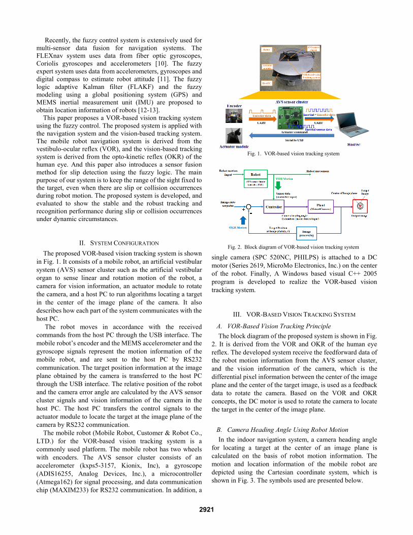
II. SYSTEM CONFIGURATION The proposed VOR-based vision tracking system is shown
in Fig. 1. It consists of a mobile robot, an artificial vestibular system (AVS) sensor cluster such as the artificial vestibular organ to sense linear and rotation motion of the robot, a camera for vision information, an actuator module to rotate the camera, and a host PC to run algorithms locating a target in the center of the image plane of the camera. It also describes how each part of the system communicates with the host PC.
The robot moves in accordance with the received commands from the host PC through the USB interface. The mobile robot’s encoder and the MEMS accelerometer and the gyroscope signals represent the motion information of the mobile robot, and are sent to the host PC by RS232 communication. The target position information at the image plane obtained by the camera is transferred to the host PC through the USB interface. The relative position of the robot and the camera error angle are calculated by the AVS sensor cluster signals and vision information of the camera in the host PC. The host PC transfers the control signals to the actuator module to locate the target at the image plane of the camera by RS232 communication.
The mobile robot (Mobile Robot, Customer & Robot Co., LTD.) for the VOR-based vision tracking system is a commonly used platform. The mobile robot has two wheels with encoders. The AVS sensor cluster consists of an accelerometer (kxps5-3157, Kionix, Inc), a gyroscope (ADIS16255, Analog Devices, Inc.), a microcontroller (Atmega162) for signal processing, and data communication chip (MAXIM233) for RS232 communication. In addition, a
single camera (SPC 520NC, PHILPS) is attached to a DC motor (Series 2619, MicroMo Electronics, Inc.) on the center of the robot. Finally, A Windows based visual C++ 2005 program is developed to realize the VOR-based vision tracking system.
III. VOR-BASED VISION TRACKING SYSTEM
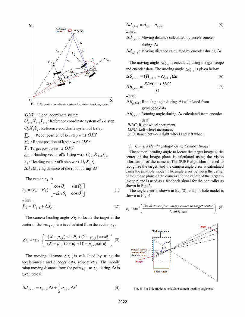
A. VOR-Based Vision Tracking Principle The block diagram of the proposed system is shown in Fig.
2. It is derived from the VOR and OKR of the human eye reflex. The developed system receive the feedforward data of the robot motion information from the AVS sensor cluster, and the vision information of the camera, which is the differential pixel information between the center of the image plane and the center of the target image, is used as a feedback data to rotate the camera. Based on the VOR and OKR concepts, the DC motor is used to rotate the camera to locate the target in the center of the image plane.
B. Camera Heading Angle Using Robot Motion In the indoor navigation system, a camera heading angle
for locating a target at the center of an image plane is calculated on the basis of robot motion information. The motion and location information of the mobile robot are depicted using the Cartesian coordinate system, which is shown in Fig. 3. The symbols used are presented below.
Fig. 1. VOR-based vision tracking system
Fig. 2. Block diagram of VOR-based vision tracking system
2921
OXY : Global coordinate system
1 1 1k k kO X Y− − − : Reference coordinate system of k-1 step
k k kO X Y : Reference coordinate system of k step
1kP − : Robot position of k-1 step w.r.t OXY
kP : Robot position of k step w.r.t OXY
T : Target position w.r.t OXY
1kr − : Heading vector of k-1 step w.r.t 1 1 1k k kO X Y− − −
kr : Heading vector of k step w.r.t k k kO X Y
dΔ : Moving distance of the robot during tΔ The vector kr is
cos sin( )
sin cosk k
k o kk k
r r Pθ θθ θ
⎡ ⎤= − ⋅ ⎢ ⎥−⎣ ⎦
(1)
where,
1 1k k kP P d− −= + Δ (2) The camera heading angle kr∠ to locate the target at the
center of the image plane is calculated from the vector kr .
, ,1
, ,
( ) sin ( ) costan
( ) cos ( )sinx k k y k k
kx k k y k k
X p Y pr
X p Y pθ θ
θ θ−⎛ ⎞− − ⋅ + −
∠ = ⎜ ⎟⎜ ⎟− + −⎝ ⎠ (3)
The moving distance 1kd −Δ is calculated by using the
accelerometer and encoder data, respectively. The mobile robot moving distance from the point
1kO − to kO during tΔ is
given below.
2, 1 , 1 , 1
12a k a k a kd v t a t− − −Δ = Δ + Δ (4)
, 1 , , 1e k e k e kd d d− −Δ = − (5)
where,
, 1a kd −Δ : Moving distance calculated by accelerometer
during tΔ
, 1e kd −Δ : Moving distance calculated by encoder during tΔ
The moving angle 1kθ −Δ is calculated using the gyroscope and encoder data. The moving angle 1kθ −Δ is given below.
, 1 , 1 , 1( )g k g k g k tθ ω− − −Δ = Ω + Δ (6)
, 1e kRINC LINC
Dθ −
−Δ = (7)
where,
, 1g kθ −Δ : Rotating angle during tΔ calculated from gyroscope data
, 1e kθ −Δ : Rotating angle during tΔ calculated from encoder data
RINC: Right wheel increment LINC: Left wheel increment D: Distance between right wheel and left wheel
C. Camera Heading Angle Using Camera Image The camera heading angle to locate the target image at the
center of the image plane is calculated using the vision information of the camera. The SURF algorithm is used to recognize the target, and the camera angle error is calculated using the pin-hole model. The angle error between the center of the image plane of the camera and the center of the target in image plane is used as a feedback signal for the controller as shown in Fig. 2.
The angle error is shown in Eq. (8), and pin-hole model is shown in Fig. 4.
1tan The distance from image center to target centerfocal lengthkε − ⎛ ⎞
= ⎜ ⎟⎝ ⎠
(8)
Fig. 3. Cartesian coordinate system for vision tracking system
Fig. 4. Pin-hole model to calculate camera heading angle error
2922

IV. SENSOR FUSION METHO
A. Sensor Fusion Concept The block diagram for sensor data fusi
controller part of the proposed system, is shthe controller part, the encoder signal (33 Hsignal (169 Hz) are synchronized with the enare used to calculate the moving distance mobile robot, which serve as the fuzzy logiat the encoder cycle. The moving distancethe encoders and accelerometer using Eqcombined using the fuzzy logic rulebasedistance. The moving angle, calculated fromgyroscope using Eq. (6) and (7), is also comfuzzy logic rulebase for the moving angrulebase is obtained from the experiments ofoccurrences. The output from the fuzzy loweighted value for the encoders and the Weighted sum, the state input for the extendis given below.
(1weighted sum d weighted value
weighted vaΔ = × Δ
+ −
(1weighted sum weighted value
weighted valuθΔ = × Δ
+ −The camera angle error between the center
the center of target in the image plane is usedupdate. Finally, the camera heading angle toin the center of the image plane is obtainedthe extended Kalman filter.
B. Fuzzy Slip Detection Modeling The mobile robot moving in indoor enviro
in dynamic circumstances and undergoes occurrences. In these environments, if
Fig. 5. Fuzzy logic controller for sensor
(a) ∆d Rulebase (a) ∆θ RNB: negative big, AO: accelerometer only GONM: negative medium AM: accelerometer medium GMZ: zero AE: both GEPM: positive medium EM: encoder medium, EMPB: positive big EO: encoder only EO
Fig. 6. The designed fuzzy logic ruleb
OD
ion, which is the hown in Fig. 7. In
Hz) and the sensor ncoder cycle, and and angle of the
ic controller input e, calculated from q. (4) and (5), is for the moving
m the encoders and mbined using the gle. Each of the f slip and collision ogic controller is
inertial sensors. ded Kalman filter,
)enc
acc
dlue dΔ
× Δ (9)
)enc
gyroueθ
θΔ
× Δ (10)
r of the image and d as measurement o locate the target d by the output of
onments is placed slip or collision
f only encoder
information is used, the location infois not correctly obtained. When inerlong term duration, it causes accumuand two-step integration.
The proposed solution for this pdetection model. The output of the fuis weighted sum of the inertial sensois used as input of the extended Kalmand (5) show the moving distance, from the encoder and accelerometercycle ∆t, respectively. The equatimoving heading angle, ∆θ, of theencoder and gyroscope data durinrespectively. Each of the rulebase experiments.
Once the inputs and the outputs arthe relationship between them muMamdani algorithm is used for theThe general "if-then" rule structure ois given in the following equation:
iR : IF ix is iA and ... THEN y is
where k is the number of rules,
fusion
Rulebase O: gyroscope only M: gyroscope medium E: both M: encoder medium O: encoder only
base
Fig. 8. ∆d Membership
Fig. 9. ∆θ Membership
Fig. 10. ∆d, ∆θ weighted value M
Fig. 7. Block diagram of controller
ormation of mobile robots tial sensors are used over
ulative errors by bias drift
problem is the fuzzy slip uzzy slip detection model
or and encoder data which man filter. The equation (4) ∆d, of the mobile robot
r data during the encoder ion (6) and (7) are the e mobile robot from the g the encoder cycle ∆t, has been obtained from
re identified and defined, ust be established. The fuzzy inference system.
of the Mamdani algorithm
iB (for i=1, 2, ..k) (11)
ix is the input variable
p function
p function
Membership function
part for sensor fusion
2923

(antecedent variable) and y is the output variable (consequent variable).
For the fuzzy logic controller, we translated our knowledge base into the fuzzy logic rulebase shown in Fig. 6. The membership functions used as the input and the output of the system are shown in Fig. 8, 9 and 10.
C. Sensor Fusion Using Extended Kalman Filter In this section the heading angle of the camera on the
mobile robot is estimated by inserting the output of the fuzzy logic controller in the input of the discrete time extended Kalman filter. The measurement of the actual heading angle of the camera is obtained by adding the angle from the DC motor encoder and the error angle from the image processing of the feedback signal.
The state model predicts the coordinates of the state statex .
( ) ( ) ( ) ( )T
x yx k p k p k kθ⎡ ⎤= ⎣ ⎦ , ~ (0, )k Qω (12)
where, ( )xp k : Mobile robot x-coordinate
( )yp k : Mobile robot y-coordinate
( )kθ : Mobile robot heading angle
The state x is induced from the input u which consists of
the weighted sum dΔ and θΔ . The input u is the output of the fuzzy logic controller.
[ ]( ) Tu k d d θ= Δ Δ Δ (13)
( ) ( 1) ( ( 1) ( 1)) cos( ( 1))x xp k p k d k k kω θ= − + Δ − + − − (14)
( ) ( 1) ( ( 1) ( 1))sin( ( 1))y yp k p k d k k kω θ= − + Δ − + − − (15)
( ) ( 1) ( ( 1) ( 1))k k k kθ θ θ ω= − + Δ − + − (16) The mobile robot’s x-coordinate, y-coordinate and heading angle are shown in Eq. (14), (15) and (16). It is updated every 0.03 s (33 Hz), which is the wheel encoder cycle.
The measurement model updates the coordinates of the state vector x . The measurement of the actual heading angle,
kz , of the camera is obtained by Eq. (3) with ~ (0, )kv R . The partial derivative matrix is obtained from Eq. (14),
(15), (16), and (3).
1
1 1 11
1 1 1 1ˆ
1 0 ( )sin0 1 ( ) cos0 0 1k
k k kk
k k k kx
dfF dx
ω θω θ
+−
− − −−
− − − −
− Δ +⎡ ⎤∂ ⎢ ⎥= = Δ +⎢ ⎥∂
⎢ ⎥⎣ ⎦
(17)
1
11
1 1ˆ
cos 0 00 sin 00 0 1k
kk
k kx
fLθ
θω +
−
−−
− −
⎡ ⎤∂ ⎢ ⎥= = ⎢ ⎥∂
⎢ ⎥⎣ ⎦
(18)
2 2 2 2ˆ
( ) ( ) 1( ) ( ) ( ) ( )
k
yk xk
x x y x y
Y Sh X SHx X S Y S X S Y S−
⎡ ⎤−∂ − −= = ⎢ ⎥∂ − + − − + −⎢ ⎥⎣ ⎦
(19)
[ ]ˆ
1k
kk
x
hMv −
∂= =∂
(20)
Fig. 11 shows the operation of the extended Kalman filter.
The filter estimates the process state x at time k and estimate the covariance P of the error in the estimate. The filter then obtains the feedback from the measurement. Using the Kalman filter gain K and the measurement z , it updates the state x and the error covariance P . This process is repeated as new measurements come in, and the error in estimation is continuously reduced [14].
V. EXPERIMENTAL RESULTS To evaluate the proposed vision tracking system, the
experimental environment was setup as shown in Fig. 12. The driving velocity and the rotation velocity of the mobile robot mounted on our system are 0.2 m/s and 30 deg/s, respectively. The initial position of the mobile robot is 1.8 m away from the target. In the recognition test, the SURF based recognition
Fig. 12. Experimental environment
Fig. 11. Operation of the extended Kalman filter
2924
program is used. In the case of accurate tracking and recognition, the target appears in the image of the camera, and a red square is formed on the edge of the target.
To verify the basic performance of the system, we experimented with linear and rotational motion. For the linear motion, the robot move forward by 0.4 m, backward by 0.8 m, and forward by 0.4 m to initial position. For the rotational motion, the robot rotates clockwise by 90 deg, anticlockwise by 180 deg, and finally clockwise by 90 deg to come to initial position. The tracking success rate is 100 %, and the recognition rate is above 95 % for the both motion scenarios. Due to the blurring effect, the target in some images cannot be recognized successfully.
Since the main purpose of our system is to keep the range of the sight fixed to the target under the dynamic circumstances, we generated the intentional collision and slip by keeping an obstacle near the robot as shown in Fig. 12. The obstacle is placed 0.1 m away from the robot in the forward direction. The mobile robot moves forward by 0.1 m, collides with the obstacle, and suffers slip while the robot keep moving by 0.4 m. After that the mobile robot moves backward by 0.5 m, and then forward by 0.4 m to initial position. In the slip test using our system, the tracking success rate is 100 % and the recognition rate is above 90 %. When compared with the slip test using the encoder only, the tracking success rate and recognition rate of our system are remarkably high. The evaluation results, the tracking success rate and recognize rate, are shown in Table 1.
VI. CONCLUSIONS In this paper, we developed the VOR and OKR based
vision tracking system for the mobile robot using the robot motion information and vision information. The main purpose of our system is to keep the range of the sight fixed to the target, even when there are slip or collision occurrences during robot motion. In the control scheme, the fuzzy logic controller is used in detecting slip or collision occurrences, and uses sensor data fusion. To calculate the rotation angle of the camera accurately, the extended Kalman filter estimates the robot motion information using the output of the fuzzy
logic controller and the vision information from the camera. The proposed system is developed, and experimented by mounting it on the top of the indoor mobile robot. The experiment results show the stable and the robust tracking and recognition performance during slip or collision occurrences under the dynamic circumstances.
REFERENCES [1] Thomas D. L., Optimal Fusion of Sensors, Department of Automation
Technical University of Denmark, PHDEssay, pp. 1-9, 1998. [2] Green D.N., Sasiadek J.Z., and Vukovich G.S., “Path Tracking
Obstacle Avoidance and Deal Reckoning by an Autonomous Planetary Rover”. In: Proc. IEEE International Conference on Robotics and Automation, San Diego, CA, pp. 1300-1305, 1994.
[3] Carelli R., Santos-Victor J., Roberti F., Tosetti S., “Direct Visual Tracking Control of Remote Cellular Robots”. Robotics and Autonomous Systems Journal, vol. 54, pp. 805-814, July, 2006.
[4] Mohamed Jallouli, Lobna Amouri, Nabil Derbel, “An Effective Localization Method for Robot Navigation through Combined Encoders Positioning and Retiming Visual Control”. Journal of Automation, Mobile Robotics & Intelligent Systems, vol. 3, pp. , Nov. 2009.
[5] C. Harris and M. Brady, “A Combined Corner and Edge Detector”. Proc of the 4th Alvey Vision Conference, pp. 147-151, 1988.
[6] S. M Smith and J. M Brady, “SUSAN A New Approach to Low Level Image Processing,” Defense Research Agency, Technical Report no. TR95SMS1, Farnborough, England, 1994.
[7] E. Rosten and T. Drummond, “Machine Learning for High-Speed Corner Detection”. Proc, of the 9th European Conf. Computer Vision, pp. 430-443, 2006.
[8] J. P. Lewis, “Fast Normalized Cross-Correlation”. Vision Interface, pp. 120-123, 1995.
[9] D. G Lowe, “Object Recognition from Local Scale-Invariant Features”. Proc. Of the International Conf. Computer Vision, pp. 1150-1157, 1999.
[10] Lauro Ojeda and Johann Borenstein. “FLEXnav: Fuzzy Logic Expert Rule-based Position Estimation for Mobile Robots on Rugged Terrain”. Proc. of the 2002 IEEE International Conference on Robotics and Automation, pp. 317-322, May, 2002.
[11] Wang J-H and Gao Y. “Fuzzy Logic Expert Rule-Based Multi-Sensor Data Fusion for Land Vehicle Attitude Estimation”. Proc. 19th Int. Committee on Data for Science and Technology (CODATA) Conf., Nov, 2004.
[12] J.Z. Sasiadek, Q. Wang and M.B. Zeremba. “Fuzzy Adaptive Kalman Filtering for INS/GPS Data Fusion”. Proc. of the 15th IEEE International Symposium on Intelligent Control (ISIC 2000), July, 2000.
[13] W. Abdel-Hamid, T. Abdelazim, N. El-Sheimy, and G. Lachapelle. “Improvement of MEMS-IMU/GPS Performance Using Fuzzy Modeling”. The Journal of Global Navigation Satellite Systems, 2006
[14] V. Subramanian, T. F. Burks, W. E. Dixon. “Sensor Fusion Using Fuzzy Logic Enhanced Kalman Filter for Autonomous Vehicle Guidance in Citrus Groves”. American Society of Agricultural and Biological Engineers, 2009
TABLE I EXPERIMENTAL RESULTS
Robot trajectory Tracking success rate Recognition rate
Translational motion (±0.4 m)
100 % 98.5 %
Rotational motion (±90 deg)
100 % 96.7 %
Slip circumstance (Proposed system)
100 % 91.2 %
Slip circumstance (Encoder) 73.6 % 73.6 %
Tracking success rate (# of successful tracking / # of image frame) Recognition rate (# of successful recognition / # of image frame)
2925


![PRINCIPLE COMPONENT ANALYSIS AND FUZZY … COMPONENT ANALYSIS AND FUZZY LOGIC BASED THROUGH WALL IMAGE ENHANCE- ... image fusion [22,23] and statical ... weight assignment using fuzzy](https://static.fdocuments.net/doc/165x107/5aaf62277f8b9aa8438d3a5f/principle-component-analysis-and-fuzzy-component-analysis-and-fuzzy-logic-based.jpg)