Sensing for robotics and control s set13
46
Sensing for Robotics and Control ME 4135 R. R. Lindeke
-
Upload
misgina2005 -
Category
Engineering
-
view
147 -
download
3
Transcript of Sensing for robotics and control s set13

Sensing for Robotics and Control
ME 4135
R. R. Lindeke

General Ideas about Sensors
Sensor are truly systems! Sensors systems consist of three separable
ideas: Informational sources: physically measurable data
sources (light beams, audio beams, electrical fields, etc) Detector areas: Devices that react to changes in the
informational sources Data Interpreters: devices (hard or soft based) that
convert informational changes into useful information

Sensor Topics
Positional Control Sensing– Kinesethic Sensing
Resolvers Absolute Encoders Incremental Encoders
Environmental Sensors– Contact
Point Field Sensors
– Proximity – typically single point– Remote
Single Point Field Sensors
Kinesethic Sensing
These sensors provide feedback information to the joint/link controllers (servo information)
They use analog or digital informational responses
We will explore 3 generally used types:– Resolvers– Absolute Encoders– Incremental Encoders

Resolvers
Operating principle is that a charged rotating shaft will induce voltage on stationary coils
Secondary Voltages are related to Primary voltage as Sin and Cos ratios of the primary field voltage

Resolver Ideas:
Typically we use 2 stators one (not shown) mounted normal to an axis that is 90 away from the one thru Winding A

Resolvers, cont.
Position is determined for computing stator ratio
Winding A carries Sin signal
Winding B carries Cos signal
A/B = tan so Shaft position
=Atan2(B_Reading, A_Reading)
of interest

Resolver Issues
These devices are susceptible to Electrical Noise – must be highly shielded
Usually use gearing to improve resolution Typically are expensive but very rugged for
use in harsh “shock motion” environments
Optical Encoder Positional Sensors
Based on Photoelectric source/receiver pairs Looks for change of state as changing receiver
signal level (binary switching) Uses a carefully designed disk with clear and
opaque patches to control light falling on a fixed sensor as disk rotates
Can be made ‘absolute’ with several pairs of emitters/receivers or Incremental with 2 ‘out of phase’ photosensors

Optical Servo Measurement Systems
Absolute Encoders– Use Glass Disk marked for positional resolution– Read digital words (0010111011) at receiver to
represent shaft position– Commonly Available with up to 16 bits of
information (216) to convert into positional resolution
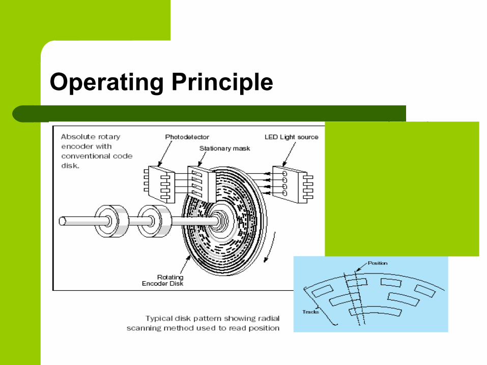
Operating Principle
Zdcvkpsdjfpsdjfgoipsdjfg’oadgn’oiardfgnd’oikrjghdar’okgjnsldkfgknllkknresffzsdfsdfkjfksdf;kkjnflll
l

Absolute Encoders – optical disks

Absolute Encoder Variations – 8bit
Comparing Natural Binary to Gray Code
Natural Binary give actual position when read– Actual position is known w/o analysis
Gray code is designed so only one bit changes “at a time”– Where Bit change is subject to positional errors
as light “bleeds” around patch edges Gray codes are, therefore, less error prone,
but require an ‘intelligent converter’ to give actual shaft position
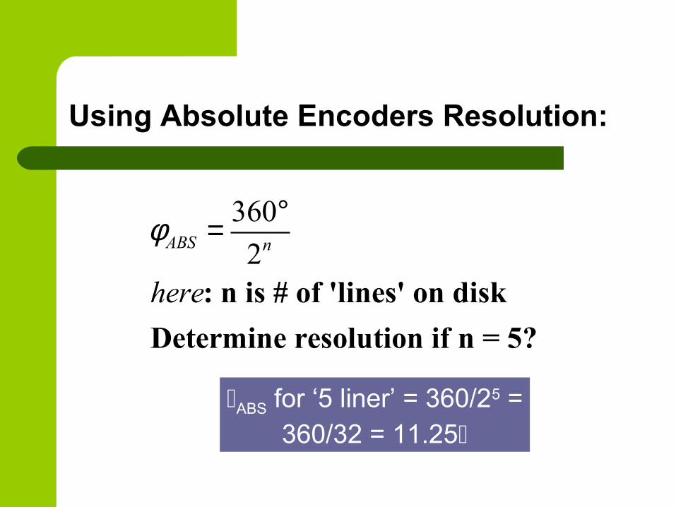
Using Absolute Encoders Resolution:
360
2: n is # of 'lines' on disk
Determine resolution if n = 5?
ABS n
here
φ °=
ABS for ‘5 liner’ = 360/25 = 360/32 = 11.25

To Improve Resolution:
Add Gearing to shaft/encoder coupling– New Resolution is:
Increase # of Lines – this increases complexity and cost of the encoder (can be a significant cost increase)
360
2
is gear ratio on encoder shaft
ABS nφ
γγ
=o
g

Absolute Encoder for 0.18 Resolution
( )360
0.182
360log 0.18log2
3.301 10.965 110.301
ABS n
n
n bits
φ = ° =
°=
= = →
o
o

Incremental Encoders
This devices use 3 pairs of Emitter/receivers
Two are for positional resolution, the third is a ‘calibrator’ marking rotational start point
Sine wave is observed due to leakage (light bleeding) around opaque patches!

Incremental Encoders
The positional detector uses what is called “Quadrature” techniques to look at the changing state of the 2-bits reporting position for each opaque/clear patch on the optical disk

Incremental Encoders
Notice the “square wave” quadrature signals
– they are offset by “½ phase” Each patch resolves into 22
or 4 positions! Without hardware change,
resolution is a function of the number of patches – or lines

Incremental Encoders
2
360 360
2 4INCpatch patchC C
φ = =o o
g
For 500 line Inc. encoders, resolution = .18 (w/o gearing)
Consider a 500 ‘Line’ incremental encoder?

Comparing Absolute and Incremental Encorders:
Incremental are usually cheaper for same level of resolution
Absolute are able to provide positional information at any time under power– Incremental must be homed after power loss to
recalibrate count numbers
Compared to resolvers, encoders are fragile so must be shock protected during operation

Environmental Sensors
These sensors provide ‘code decision making’ power to the Manipulator
These sensors can be simple Single point devices, Simple devices typically trigger yes/no decisions with switch
changes These sensors can be complex 2-D array (or even 3-
D field) devices Typically the receivers are complex arrays The data interpreters are sophisticated software and hardware
devices They can add “intelligence” for decision-making by the
manipulator
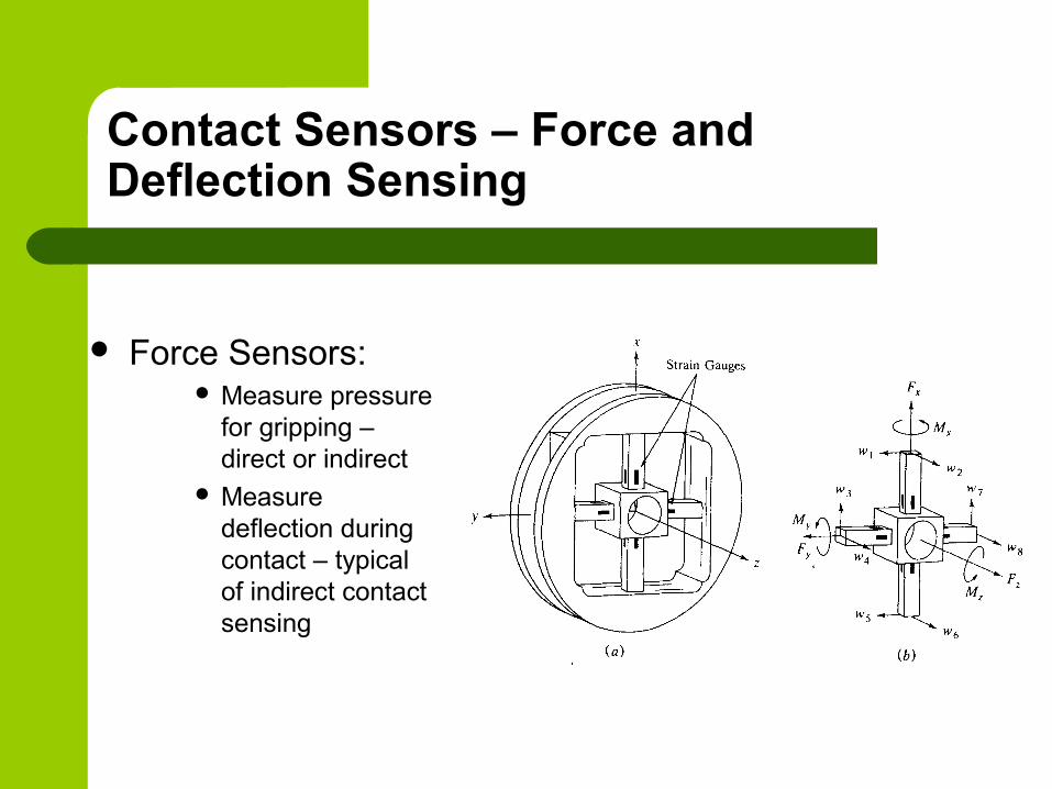
Contact Sensors – Force and Deflection Sensing
Force Sensors: Measure pressure
for gripping – direct or indirect
Measure deflection during contact – typical of indirect contact sensing
Contact Sensing
Indirect contact sensors use Strain Gages (and Hooke’s Law: Stress = E*Strain)
The strain gage is a resistive device that exhibits a change in resistance due to changes in shape (length or width)
The Strain Gage is mounted into a carefully built (and calibrated) Wheatstone bridge
small changes to the strain gages resistance, observed while using a highly linear voltage source, are calibrated against observed deflection
This ‘bar’ deflection is strain and multiplying the strain times the bar’s modulus of elasticity yields stress and hence applied force!
Stress = Force/Areabar

Contact Sensing
Other contact sensor are “Direct Reading”
These devices use the piezoelectric principle (effect) of the sensor material
Piezoelectric effect states that in certain material (quartz and some silicates) applied forces (dynamically) will cause a minute – but measurable – flow of electrons along the surface of the crystal based on di-polar disruption due to shape change
This flow is measure as a “Nano-current” The Current is linearized, amplified and
measured against a calibrated force

Contact Sensing
A second general type would be the class of “Micro-Switches”
Like at the end of the Conveyor in the S100 cell
Typically, applied forces directly move a common contact between NC and NO contact points

Examples of Micro-Switches:
One Directional Reed Switch:
Omni-Directional Reed Switch:
Roller Contact Switch:
Etc., etc., etc.!!!

Tactile Sensors – “feeler arrays”
Potential Advantages of Tactile Sensors:– They generate far fewer data bits (compared to
visual arrays) leading to simpler interpretation analysis
– Collection is more readily controlled – we completely control background and contrast
– The properties we measure are very close to (exactly?!?) the properties we desire

Defining the “Ideal” Tactile Sensor
They must be rugged and compliant to faults in the manufacturing (operating) environment
They should be “Smart” – That is able to process most of the data into information for decision making locally
– they send only results to the main controller Resolution should be on the order of about 100 mils
(about 10-4 inch) Sensors should respond to forces on the order of
about 5 -10 gmforce (0.1 N or 0.022 lbf)

Tactile Arrays:
Machine Equivalent of Human Skins
Use arrays of micro-sized switches or other methods to detect shapes and sizes due to contact images of “made” Switches

Tactile Arrays
This device “measures” shapes and sizes by determining which of an array of target points have been charged
Targets are “charged” through contact with the conductive Elastomer skin and the PC ‘board’ targets

Tactile Arrays
In this device, a series of thin rods are pushed into an object
A “positive” image of the object is produced by the displaced rods
In modern sensors, displacement of each rod is measured by the detector/interpreter system – this might be a vision system located normal to the direction of contact application or an LVDT unit at each ‘rod’

Tactile Arrays
The Anisotropic conductive rubber sensor
The ACR and gold contact surface is separated when unloaded
As load is applied contact patches grow indicating shape and size of external object and force being applied

Proximity Sensors:
Devices, including Photocells, Capacitance sensors and Inductive sensors, that can be used in areas that are near to but not directly contacting an object to be sensed
Like all sensors they use structured signal sources, receive changes of state in their energy (sensing) fields and interpret these changes with signal changes to the “outside”

Photo Sensors
The modern photosensor (in the proximity range) emits modulated light (at infrared or near-infrared wavelengths). The emitters are LED.
The receivers (phototransistors) are ‘tuned’ to be sensitive to the wavelength of the source emitter during the ‘on’ steps in the modulated output stream
The interpreters are (typically) transistors that switch the power (or ground) source on to the output lead

Diffuse Mode Photosensor
In proximity mode, the device is looking for its own emitted beam reflected back to its paired receiver
The level of light falling on the receiver to trigger positive response can be ‘tuned’ to the task
The sensors can be tuned to “Light-Operate” or “Dark-Operate”
Light operate means positive output when reflective light is sensed
Dark operate means positive output when NO reflective light is sensed
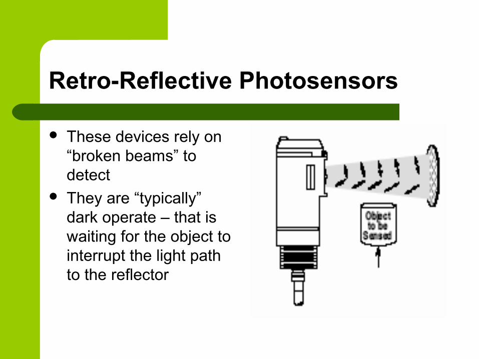
Retro-Reflective Photosensors
These devices rely on “broken beams” to detect
They are “typically” dark operate – that is waiting for the object to interrupt the light path to the reflector
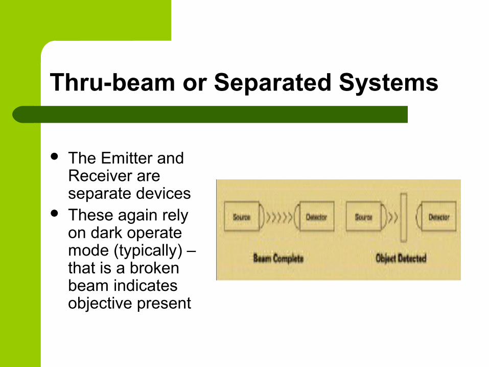
Thru-beam or Separated Systems
The Emitter and Receiver are separate devices
These again rely on dark operate mode (typically) – that is a broken beam indicates objective present
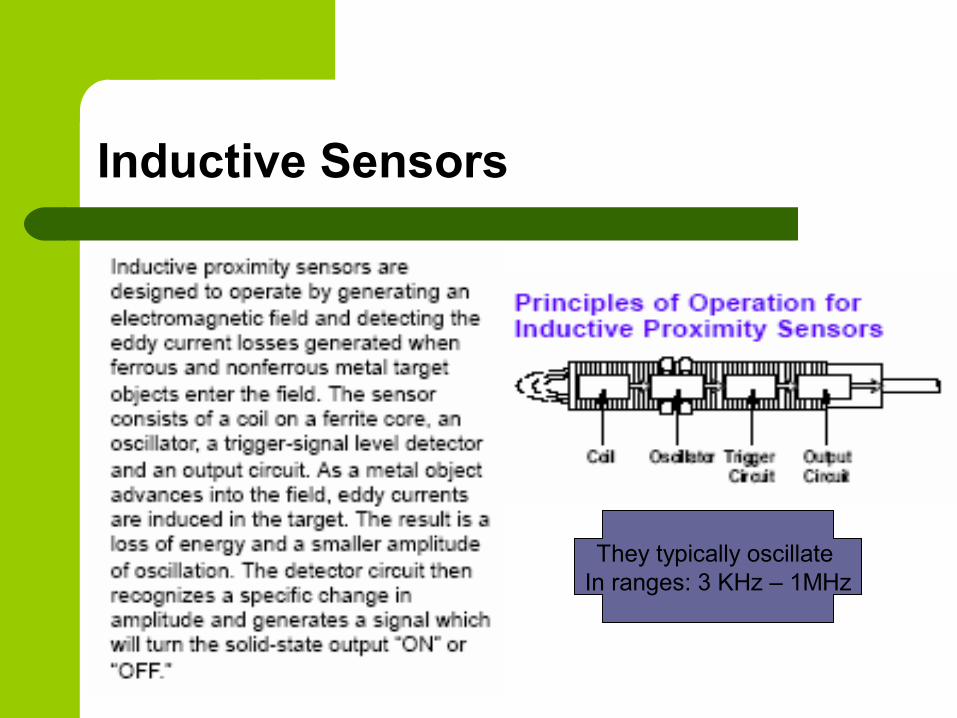
Inductive Sensors
They typically oscillate In ranges: 3 KHz – 1MHz

Inductive Sensors
Shielded types have slightly longer range but smaller field of view

Uses:
Inductive Sensors can (only) detect metals as they draw power by induced surface currents (eddy currents) The more magnetic the metal the greater the
sensor’s range
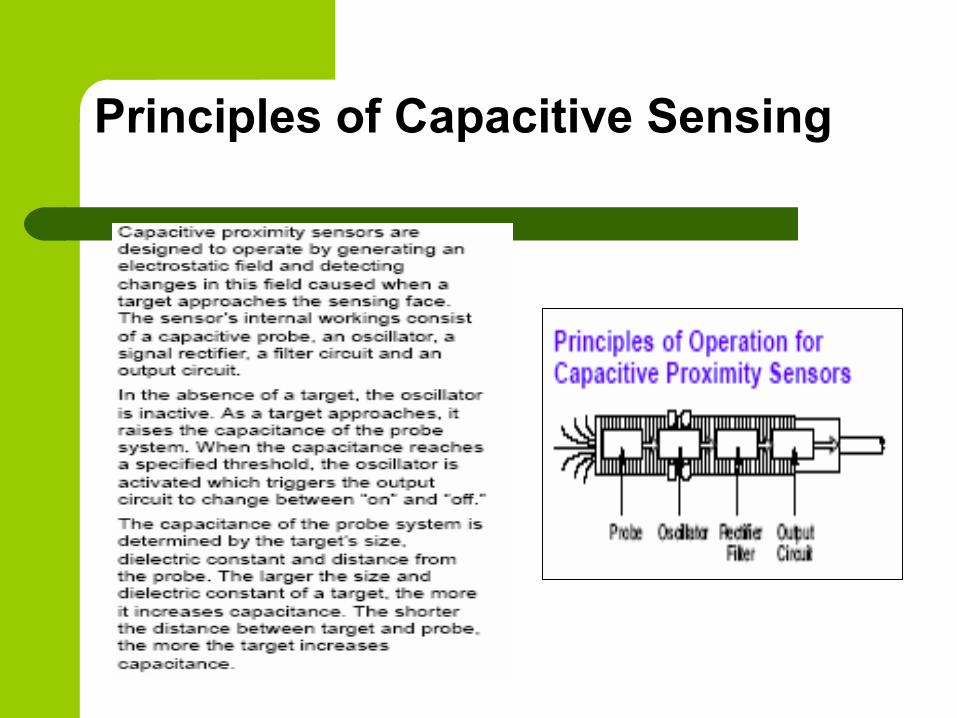
Principles of Capacitive Sensing

Uses And Capabilities
Capacitive Sensors are able to detect any material that raises the field dielectric in the vicinity of the sensor– In air this is nearly any other material!

Uses of Capacitive Sensors:
Typical Application of Capacitive Sensor:
Detecting Liquid (H2O) levels in bottles
When properly calibrated, the sensor can detect any higher Dielectric Material thru
any lower Dielectric Material

Dielectric Values of Various Materials: