

sensazone - Heat Tracing€¦ · 0118 969 1611 | [email protected] | 2Sensorpositioning...
12
sensazone 0118 969 1611 | [email protected] | www.cistermiser.co.uk installation guide When movement is detected the sensor will send a pulse to the valve(s) and the LED will flash green once every three seconds. The valve(s) open allowing water to flow into the washroom feeding the terminal water fittings for either 15 or 30 minutes, as configured by the installer; after this period a second pulse will be sent to the valve(s) to close them. The timer is reset every time movement is detected. If no movement is detected after 12 hours the sensazone will activate a hygiene cycle. 1 Introduction sensazone is an intelligent PIR sensor which controls the water supply to the washroom via solenoid valves. It can control up to three solenoid valves for hot, cold and rain/grey water.
Transcript of sensazone - Heat Tracing€¦ · 0118 969 1611 | [email protected] | 2Sensorpositioning...

sensazone
0118 969 1611 | [email protected] | www.cistermiser.co.uk
installation guide
When movement is detected the sensor will send a pulseto the valve(s) and the LED will flash green once everythree seconds. The valve(s) open allowing water toflow into the washroom feeding the terminal water fittingsfor either 15 or 30 minutes, as configured by the installer;after this period a second pulse will be sent to the valve(s)to close them. The timer is reset every time movementis detected.
If no movement is detected after 12 hours the sensazonewill activate a hygiene cycle.
1 Introductionsensazone is an intelligent PIR sensor which controls the water supply
to the washroom via solenoid valves. It can control up to three
solenoid valves for hot, cold and rain/grey water.
jo soulsby
TH
jo soulsby
TH

0118 969 1611 | [email protected] | www.cistermiser.co.uk
2 Sensor positioning
supplied parts1 Solenoid valve**
2 2 x 22mm compression fittings*
3 Inlet filter*
4 Fibre washer*
5 Sensor assembly consisting ofsensor unit and backplate
6 Mains power adaptor
7 2 x Rawlplugs
8 2 x #6 x 1 1/2" screws
9 4 x #4 x 1/2" screws
10 4 x sticky pads
11 Extension cable to mains poweradaptor (1.25m)
12 Extension cable to solenoid valve (3m)
11
12
6
7 x 2
8
9
10
5
1**
2*
3*
4*
x 2
x 4
x 4
x 2
Minimum 1 metre
Door
Min
imum
1m
etre
** Solenoid valve either 15mm, 22mm, 1" or 11/4"* Only supplied with 15mm or 22mm
Dan Macey
TH2

0118 969 1611 | [email protected] | www.cistermiser.co.uk
3 Installation schematic
Install valve onto the water supply leading into thewashroom (hot, cold and rain/grey water) or asclose as practically possible to the entry point tosuit the pipe layout.
Valve installation
AAC
B
Detection Zone: 5 metres
2.2m
etres
Ceiling
Isolating Valve(not supplied)
Cold
water
supp
lyto
washroom
Hot
water
supp
lyto
washroom
Grey
orrainw
atersup
ply
tow
ashroomA
Note: Sensor should beinstalled approximately 1metre from the entranceto the room.
jo soulsby
TH

0118 969 1611 | [email protected] | www.cistermiser.co.uk
false ceiling1. Detach the backplate from the sensor unit.
2. Offer the backplate to the ceiling and markposition of holes.
3. Drill 6mm diameter holes and insert Rawlplugs.
4. Drill an additional hole of 10mm diameterbetween the two 6mm holes as shown below.
5. Screw the base plate to ceiling.
6. Feed the wire through the large (10mm) centrehole and secure the sensor unit to the base plate.
7. Twist sensor unit clockwise into backplate tolock into position.
solid ceiling1. Detach the backplate from the sensor unit.
2. Offer the backplate to the ceiling and mark theposition of holes. Pay particular attention to ensurethat the ‘wire exits’ are correctly positioned foryour installation.
3. Drill 6mm diameter holes and insert Rawlplugs.
4. Screw base plate to ceiling.
5. Ensure wire is fed through the ‘wire exits’ asdisplayed on the sensor. If the wire is required to goout of the same exit ensure that the wire is routedaround the sensor as shown in the diagram below.
6. Secure sensor unit to base plate and twistclockwise to lock into position.
Sensor installation
Wire the mains adaptor into a 1A fused spur.
NOTE: this should not be further than 3 metresfrom the sensor unit.
Mains power adaptor
10mm6mm 6mm
B
C
jo soulsby
TH

0118 969 1611 | [email protected] | www.cistermiser.co.uk
4 Final water and electrical connectionssingle valve installationsConnect the spade connectors from the sensor unitto the solenoid tabs taking care to connect thewires according to the label. The solenoid cablesare orange and turquoise. If these are not longenough they can be extended by up to 10 metres.
multiple valve installationsMultiple valves can be connected in parallel using the‘daisy chain’ cable provided in the additional solenoidvalve kit (AVK) as shown below. The AVK is availablefrom Cistermiser or any major plumbing merchant.Ensure that like colours are connected. Use the ‘piggyback’ connectors to loop 2 or 3 valves together asshown opposite.
power connectionConnect the power connector from the sensor unitto the mains adaptor. Colour conventions are brownfor positive and grey for negative.
MAX 3 metres fromsensor to power supply
MAX 10 metres betweensensor and furthest valve
Sensorunit
Power connector
Powersupply
NOTEShould you require extension cables for thesolenoid valves please contact Cistermisertechnical services.
jo soulsby
TH

0118 969 1611 | [email protected] | www.cistermiser.co.uk
5 Testing and commissioningstart up operationWhen the sensazone is powered up the LED willbe a constant amber for up to 15 seconds afterwhich it will flash amber for 5 seconds. The watersupply(ies) into the washroom will now be on forthe default run-on time of 15 minutes. The defaultrun-on time can be changed to 30 minutes. Seethe advanced setting guide in section 8.
normal operationWhen movement is detected, a pulse is sent toopen the valve(s) and the LED will flash green once
every three seconds for the duration of the run-ontime. If movement is detected during the run-ontime the timers are re-set and will keep the valve(s)open for a further 15 or 30 minutes from the timemovement was last detected.
testingThis can be done using the Infrared ConfigurationUnit (ICU) which is not supplied but is availablefrom Cistermiser or any major plumbing merchant.
6 Usage advice and specification
factory settings
specificationControl classification: Independent
Maximum load: 3 x 2W 0.33A (6VDC) EMC emissions tested at load
Rated temperature range: 0-40 deg C
Action classification: Type 1.Y
Pollution classification: Degree 1
Ingress protection: IP55 or IP65 (with respect to room whensmooth, non-porous ceiling tile used)
Solenoid extension cable: 3m length x 1.5mm² conductor size
Mains power extension cable: 1.25m length x 0.5mm² conductor size
Range: ~2.2m high x 5m diameter
Sensitivity setting: Medium
Hygiene rinse: On (30 minutes every 12 hours)
Run-on time: 15 minutes
Power requirements: 6V DC regulated from mains adaptor. (Fused spur required)
15mm & 22mm valves: Max pressure 6 barMin pressure 0.5 bar
1" and 1.25" valves: Max pressure 5 barMin pressure 0.5 bar
jo soulsby
TH
0118 969 1611 | [email protected] | www.cistermiser.co.uk
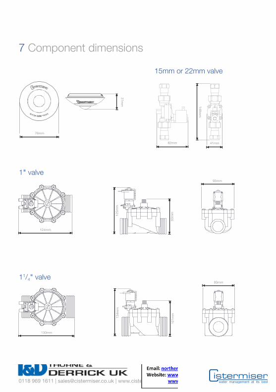
7 Component dimensions
134m
m
101m
m
93mm
130mm
125m
m
93m
m
93mm
124mm
1" valve
11/4" valve
15mm or 22mm valve
76mm
41mm82mm
31mm
148mm
jo soulsby
TH

8 Advanced settings guide – manual configuration
1 Disconnect power, wait for 5 seconds and reconnect.
2
3
When flashing amber
If a hand is not placed over the sensor, it will go into normal operation mode.
Cup hand over the sensor for 2 seconds onlyto enter into the run-on time configurationmode. LED will be constant green.
You are now in configuration mode
Option 1: Run-on time adjustment (15 minutes)
Wait for singlegreen flashingLED.
A Cup your hand over the sensor for2 seconds to select this option.The LED will be constant green for5 seconds.
B
Option 2: Run-on time adjustment (30 minutes)
Wait for doublegreen flashingLED.
A Cup your hand over the sensor for2 seconds to select this option.The LED will be constant green for5 seconds.
B
Sequence of programme once option has been selected
Once your optionhas been chosen,the LED will beconstant greenfor 5 seconds.
A The LED will thenbe constantamber for5 seconds.
B
1 2
The LED will thenflash amber, givingthe opportunity tore-enter configurationmode.
C
NOTE: Sensor LED is constant amber for up to 15 seconds while checking ambient light level. If theambient light level is not sufficient the sensor will automatically go into normal operation. To changesettings increase light level in the room or purchase ICU.
NOTE: If a hand is held over the sensor for more than 10 seconds the sensor will go into normaloperation mode.
The installer can adjust the run-on time as follows:

9 Infrared Configuration Unit (ICU) guide
activating walk testWhen the sensazone is in normal operation, pointthe ICU at the sensazone and press 1 . Thesensazone will flash green every time it detectsmovement. This confirms that the unit is operatingas it should be. After two minutes of nomovement, the sensor returns to normal operation.
The product must be put into ICU configurationmode before any setting can be configured.
activating clean modePoint the ICU at the sensazone (in normaloperation mode) and press the clean button .This will lock the solenoid valve(s) open or closed.
Constant green LED: valves locked open.
Constant red LED: valves locked closed.
Repeatedly pressing the clean mode will togglebetween locked open and closed. If a delay of 4seconds occurs after pressing the clean button,
the valve(s) remain locked in their state for 10minutes after which the unit will default back tonormal operation.
entering configuration modePoint the ICU towards the sensazone sensor andpush the configuration button. Activation ismost effective when the configuration button isheld down as the ICU is brought close to thesensor.
It can take up to 3 seconds for the product tosense the ICU. The sensazone will return tonormal operation if there are no button pressesfor 30 seconds.
Activates cleaning mode
Activates ICU configuration mode
Decreases setting
Increases setting
Checks the setting being altered
Saves changes and exits ICU configuration mode
Quits ICU configuration mode without saving changes
Configures sensor range
Configures run-on time
12 hour hygiene cycle activation
Resets to default factory settings
1459
button descriptions
NOTE: Not supplied but available from Cistermiser or any major plumbing merchant.

0118 969 1611 | [email protected] | www.cistermiser.co.uk
configuring sensor sensitivity (range)Enter into configuration mode. Point the ICU at thesensazone and press the 1 : the sensor blinksgreen once.
Decrease or increase the sensor range by pressingthe and buttons respectively. The sensor blinksgreen every time or is pressed and blinks redwhen the minimum or maximum value is reached.
Press button to verify the sensor sensitivitysetting: the sensor displays the current setting byflashing green.
Single flash: minimum sensitivity setting.
Double flash: medium sensitivity setting.
Triple flash: maximum sensitivity setting.
Save setting and exit ICU configuration mode bypressing the button. The sensor will blinkgreen for 1 second and then constant amber for3 seconds.
To exit without saving press the button.The sensor will blink red for 1 second and thenconstant amber for 3 seconds.
configuring occupancy (run-on) timeEnter into configuration mode. Point the ICU atthe sensazone and press the 4 : the sensorblinks green once.
Decrease or increase the run-on time by pressingthe and buttons respectively. The sensorblinks green every time or is pressed andblinks red when the minimum or maximumvalue is reached.
Press button to verify the sensor rangesetting: the sensor displays the current settingby flashing green.
Single flash: 15 minute run-on time set.
Double flash: 30 minute run-on time set.
Save setting and exit ICU configuration mode bypressing the button. The sensor will blink greenfor 1 second and then constant amber for 3 seconds.
To exit without saving press the button.The sensor will blink red for 1 second and thenconstant amber for 3 seconds.
activating the 12 hour hygiene cycleEnter into configuration mode. Point the ICU atthe sensazone and press the 5 : the sensorblinks green once.
Pressing the and buttons switches thehygiene cycle function on or off respectively.Press the button to verify the setting: thesensor displays the current setting by flashinggreen.
Single flash: hygiene cycle OFF
Double flash: hygiene cycle ON
Save setting and exit ICU configuration mode bypressing the button. The sensor will blinkgreen for 1 second and then constant amber for3 seconds.
To exit without saving press the button.The sensor will blink red for 1 second and thenconstant amber for 3 seconds.
reset to factory settingsEnter into configuration mode. Point the ICU at thesensazone and press the 9 : the sensor blinksgreen once. This returns all settings to the defaultfactory settings.
To save the setting and exit ICU configurationmode press the button. The sensor will blinkgreen for 1 second and then constant amber for3 seconds.
To exit without saving press the button.The sensor will blink red for 1 second and thenconstant amber for 3 seconds.
To activate the walk test and cleaning mode thesensazone should be in normal operating mode.

0118 969 1611 | [email protected] | www.cistermiser.co.uk
10 Frequently asked questions
water at outlets at all timesLED not lit Check electrical power supply to the sensor and all electrical
connections to the valve. If electrical power confirmed pleasecontact Cistermiser for further advice.
Constant green LED The unit has been left in the locked open position and willremain in this position for 10 minutes after which it will go intonormal operation. However the clean button on the ICU canbe pressed to return to normal operation mode.
Valves not opening or closing Check all electrical connections and ensure maximum cablewhen they should runs have not been exceeded. If confirmed contact Cistermiser
for further advice.
no water at outletsLED not lit Check electrical power supply to the sensor unit and all
electrical connections to the valve.
Constant red LED The unit has been left in the locked closed position and willremain in this position for 10 minutes after which it will go intonormal operation. However the clean button on the ICU can bepressed to return to normal operation mode.
LED flashing green Ensure there is a water supply to valve.every 3 seconds Ensure you have the minimum water pressure of 0.5 bar.
Check the filter at the inlet side of the valve is clear of any debris.Check all electrical connections between the sensor and valves.Check to ensure the maximum cable runs between the sensorand valve(s) have not been exceeded.There is water in one zone but not all zones. Ensure waterpressure does not exceed the maximin working pressure ofthe valve.
other issuesSingle or double red flash Check wiring: if this is correct and the problem persists please
contact Cistermiser.
Constant green LED Indicates fault with wiring between mains supply, transformerand sensor.
When initially powered, sensor Ambient light level may not be sufficient. Additional artificialgoes red and will not enter into light (a torch can be used) is required onto the sensorconfiguration mode throughout configuration.
Can I install multiple sensazones NO. Connecting multiple sensazones in parallel to a solenoidin parallel? will damage the sensor beyond repair.
What do I do if the sensor is not Conduct a walk test and if required adjust the sensor sensitivitysensing occupancy in the setting as per section 9.washroom?
jo soulsby
TH


