senior design paper final version - Virginia Techmason/Mason_f/VTBioJetBC-175UGACD.pdf · Response...
95
B Response to 2009/2010 AIAA Presented by Vir BioJet BC-175 Foundation Undergraduate Team Aircraft Desig irginia Polytechnic Institute and State University gn Competition y
-
Upload
truongtuong -
Category
Documents
-
view
218 -
download
2
Transcript of senior design paper final version - Virginia Techmason/Mason_f/VTBioJetBC-175UGACD.pdf · Response...

BioJet
Response to 2009/2010 AIAA Foundation Undergraduate Team Aircraft Design Competition
Presented by Virginia Polytechnic Institute and State University
BioJet BC-175
Response to 2009/2010 AIAA Foundation Undergraduate Team Aircraft Design Competition
Presented by Virginia Polytechnic Institute and State University
Response to 2009/2010 AIAA Foundation Undergraduate Team Aircraft Design Competition
Presented by Virginia Polytechnic Institute and State University

Member Roster:
Name:
Lawrence Hale
Nick Meadows
Mark Burns
Karun Sapkota
Elias Addleman
Aaron Friedmen
Jonathan Bonilla
Alexander Buchholz
Dr. William H Mason
Position:
Team Leader, Weights, Cost
Systems
Aerodynamics
Propulsion and Alternate Fuels
Stability and Control
Performance
Configuration Designer
Structures
Faculty Advisor
AIAA #:
276917
411929
418631
421337
416050
421374
421580
421623
Signature:
_________________
_________________
_________________
_________________
_________________
_________________
_________________
_________________
_________________

Biojet – BC-175
ii
Executive Summary
Biojet is pleased to present its response to the request for proposal from the American
Institute of Aerodynamics and Astronautics received on October 1, 2009. It calls for the
development of a commercial airliner with a capacity of 175 passengers, entering service in
2020, primarily as a replacement for the Boeing 737/Airbus A320. This vehicle is in high
demand as existing aircraft in this category were not designed from the ground up to utilize
alternate fuels. The RFP requires a reduction in emissions and improved cost effectiveness for
the operator, and Biojet provides those solutions. This aircraft will have a range of 3,500 nm
with lower fuel consumption than current aircraft. Our aircraft exceeds the design requirements
by increasing L/Dmax by 27% as compared to current aircraft in its class. The aircraft’s cruising
speed is Mach 0.8 specified in the RFP. The aircraft has a balanced field length of 5930 ft and a
landing speed of 124 knots. Additionally, the aircraft has an initial cruise altitude of 35,000 feet
and a maximum cruising altitude of 41,000 feet. As an additional requirement, Biojet designed
the aircraft to fit the class III gates that accommodate both the Boeing 737 and A320. The Biojet
concept is a tube and wing design with a V-tail, which has been used in some aircraft but has not
been used commercially. The concept is compared to the existing aircraft throughout the design
and shows benefits in many areas. Biojet utilizes advanced technologies in the design ensuring
that it fulfills the requirements of the RFP. These include the use of composite materials,
advanced airfoil design, and advanced engine technologies. Biojet is proud to present the BC-
175 as the next generation commercial airliner.

iiiiii

iviv

BioJet – BC-175
v
Contents Index of Figures ............................................................................................................................ vii
Index of Tables ............................................................................................................................ viii
Abbreviations ................................................................................................................................. ix
Nomenclature .................................................................................................................................. x
1. Introduction ................................................................................................................................ 1
1.1 RFP and Problem Analysis................................................................................................... 1
2. Configuration Concepts .............................................................................................................. 5
2.1 Current Aircraft ..................................................................................................................... 5
2.2 Hybrid Wing Body Design ................................................................................................... 7
2.3 Tube and Wing Concept ..................................................................................................... 10
2.4 Design Selection ................................................................................................................. 15
3. Biofuels .................................................................................................................................... 17
3.1 Biofuel Selection ................................................................................................................. 17
4. AERODYNAMICS .................................................................................................................. 21
4.1Wing Design ........................................................................................................................ 21
4.2 High Lift Devices ................................................................................................................ 24
4.3 Drag Analysis...................................................................................................................... 25
5. Propulsion ................................................................................................................................. 28
6. Weights ..................................................................................................................................... 31
6.1 Final Weights ...................................................................................................................... 31
6.2 Center of Gravity ................................................................................................................ 33
7. Performance............................................................................................................................. 33
7.1 Takeoff ............................................................................................................................... 34
7.2 Climbing Flight .................................................................................................................. 35
7.3 Range .................................................................................................................................. 37
7.4 Descent ............................................................................................................................... 41
7.5 Landing............................................................................................................................... 41
7.6 Mission Profile ................................................................................................................... 42
7.7 Comparison of Performance ............................................................................................ 44
8. Structures and Materials ........................................................................................................... 45
8.1 Material Comparison .......................................................................................................... 45

BioJet – BC-175
vi
8.2 V-N Diagrams ..................................................................................................................... 46
8.3 Wing Design ....................................................................................................................... 47
8.4 Control Surfaces.................................................................................................................. 48
8.5 Skin and Pressure Vessel .................................................................................................... 48
8.6 Engine Nacelle .................................................................................................................... 49
8.7 Miscellaneous ..................................................................................................................... 49
8.8 Manufacturing and Maintenance ........................................................................................ 49
8.9 Overview and Cad Drawings .............................................................................................. 50
9. Stability and Control ................................................................................................................. 52
9.1 Tail Sizing ........................................................................................................................... 52
9.2 Static Margin ....................................................................................................................... 53
9.3 Control Surface Sizing ........................................................................................................ 54
9.4 Dynamic Analysis ............................................................................................................... 57
10. Systems ................................................................................................................................... 58
10.1 Aircraft Cabin Layout ....................................................................................................... 58
10.2 Cockpit Layout.................................................................................................................. 63
10.3 Flight Control Systems ..................................................................................................... 65
10.4 Electrical Systems ............................................................................................................. 66
10.5 Pressurization .................................................................................................................... 67
10.6 Deicing System ................................................................................................................. 68
10.7 Fuel Systems ..................................................................................................................... 69
10.8 Landing Gear .................................................................................................................... 70
10.9 Noise Reduction ................................................................................................................ 72
10.10 Airport Systems .............................................................................................................. 74
10.11 Cargo ............................................................................................................................... 76
11. Cost ........................................................................................................................................ 77
11.1 Life Cycle Cost ................................................................................................................. 77
11.2 Research, Development, Testing, and Evaluation ............................................................ 77
11.3 Acquisition ........................................................................................................................ 78
11.4 Program Operating Cost ................................................................................................... 78
12. Conclusion ............................................................................................................................. 79
13. References: .............................................................................................................................. 80

BioJet – BC-175
vii
Index of Figures Figure 1.1: Current Aircraft Comparison[2] .................................................................................... 3
Figure 1.2: Boeing 737 Mission Profile .......................................................................................... 4
Figure 2.1: Three view and a 3-D drawing of the hybrid wing body concept ................................ 7
Figure 2.2: BWB Sizing optimization. ........................................................................................... 9
Figure 2.3: BWB with C-wing[10] ................................................................................................. 10
Figure 2.4: Comparison of Span Efficiency for Various Wing Types[10] ..................................... 11
Figure 2.5: Tube and Wing Design ............................................................................................... 13
Figure 2.6: Tube and Wing Sizing Optimization .......................................................................... 14
Figure 2.7: Final Design Constraint Diagram ............................................................................... 16
Figure 3.1: Comparison of Biofuel Plant Resources[12] ................................................................ 19
Figure 3.2: Algae Oil Needed for Five Billion Gal/yr Jet Fuel[14] ................................................ 20
Figure 4.1: Experimental data, transitional Reynolds number with leading edge sweep Modified from Braslow[17] .......................................................................................................... 22
Figure 4.2: NASA SC(2)-0412[18] ................................................................................................. 23
Figure 4.3: XFoil lift coefficient versus angle of attack computation and correction for NASA SC(2)-0412 .................................................................................................................. 23
Figure 4.4: High Lift Device Configuration ................................................................................. 25
Figure 4.5: Drag Breakdown[21] .................................................................................................... 26
Figure 4.6: Drag Buildup .............................................................................................................. 26
Figure 4.7: Trimmed cruise lift-to-drag ratio analysis 0.8 M, 41000 feet .................................... 27
Figure 4.8: Cruise Trim Drag Analysis 0.8 M, 41000 feet ........................................................... 28
Figure 5.1: Thrust Available vs. Altitude for PW1000G .............................................................. 30
Figure 6.1: CG movement with weight variation ......................................................................... 33
Figure 7.1: Thrust Required at 41,000 ft for BC-175 ................................................................... 38
Figure 7.2: Specific Range including drag rise for BC-175 ......................................................... 39
Figure 7.3: Contour Plot of Specific Range for BC-175 .............................................................. 40
Figure 7.4: Mission Profile for BC-175 ........................................................................................ 43
Figure 8.1: V-n Diagram ............................................................................................................... 47
Figure 8.2: Structural Diagram ..................................................................................................... 51
Figure 9.1: Tornado Model ........................................................................................................... 54
Figure 9.2: Pitch Angle vs. Velocity Required for Nose-Wheel Lift-off ..................................... 55
Figure 9.3: Roll Performance Capability with Sized Ailerons ..................................................... 56
Figure 10.1: Cabin Cross-section .................................................................................................. 59
Figure 10.2: Cabin Arrangement .................................................................................................. 60
Figure 10.3: B/E Aerospace Three Seat Cluster[47] ....................................................................... 61
Figure 10.4: B/E Aerospace Pulse Oxygen Delivery System[48] .................................................. 62
Figure 10.5: Boeing 787 Mood Lighting System[49] ..................................................................... 63
Figure 10.6: Rockwell-Collins MFD 2912 Digital Display[50] ..................................................... 63
Figure 10.7: Boeing 787 Cockpit[52] ............................................................................................. 64
Figure 10.8: BC-175 Cockpit Layout[53] ....................................................................................... 65
Figure 10.9: GKN Deicing Heat Mat[57] ....................................................................................... 68
Figure 10.10: Wing Tank Location ............................................................................................... 69

BioJet – BC-175
viii
Figure 10.11: Fuel Tank Locations ............................................................................................... 70
Figure 10.12: BC-175 Right Side View ........................................................................................ 71
Figure 10.13: BC-175 Front View ................................................................................................ 71
Figure 10.14: Boeing 787 with Goodrich Nacelle[58].................................................................... 73
Figure 10.15: A340 Main Landing Gear Noise Test Configuration[60] ........................................ 74
Figure 10.16: Airport Fueling System[61] ...................................................................................... 75
Figure 10.17: 5,000 Gallon Jet-A Refueler with 300 GPM Pump System[62] .............................. 75
Figure 10.18: LD3-45 Cargo Container[63] ................................................................................... 76
Index of Tables Table 1.1: RFP Requirements ......................................................................................................... 2
Table 2.1: Replacement Aircraft Comparison[3] [4] ......................................................................... 6
Table 2.2: Pro-Con Chart for HWB ................................................................................................ 8
Table 2.3: Pros-Cons of Tube and Wing Design .......................................................................... 12
Table 2.4: Design Selection Decision Matrix ............................................................................... 15
Table 2.5: Pros and Cons of Final Tube and Wing Design .......................................................... 16
Table 3.1: Energy Content Comparison........................................................................................ 18
Table 5.1: Various engine specifications. [22] ................................................................................ 29
Table 6.1: Iteration of TOGW for the BC-175 ............................................................................. 31
Table 6.2: Aircraft Component Weight Breakdown ..................................................................... 32
Table 6.3: Weight comparison of BC-175 .................................................................................... 32
Table 7.1: Takeoff Performance for BC-175 ................................................................................ 35
Table 7.2: Climbing Flight Performance for BC-175 ................................................................... 36
Table 7.3: Cruise Performance for BC-175 .................................................................................. 37
Table 7.4: Landing Performance for BC-175 ............................................................................... 42
Table 7.5: Comparison of Performance Characteristics[3][4] ......................................................... 44
Table 7.6: RFP Performance Requirements for BC-175 .............................................................. 45
Table 8.1: Material Comparison[34][35][36][37][38] ............................................................................. 46
Table 9.1: Engine Out Analysis .................................................................................................... 53
Table 9.2: Longitudinal Stability Derivatives ............................................................................... 56
Table 9.3: Lateral-Directional Stability Derivatives ..................................................................... 57
Table 9.4: BC-175 Dynamic Modes and Level 1 Requirements (no control system) .................. 58
Table 11.1: Research, Development, Testing and Evaluation Rates ............................................ 77
Table 11.2: Passenger Airline Systems (Cents per Available Seat Mile)[65] ................................ 78

BioJet – BC-175
ix
Abbreviations AIAA – American Institute of Aeronautics and Astronautics ANOPP – Aircraft Noise Prediction Program APS – Air Purification System APU – Auxiliary Power Unit BFL – Balanced Field Length BWB – Blended Wing Body CFRP – Carbon Fiber Reinforced Plastic CFRP – Carbon Reinforced Plastic CG – Center of Gravity EBHA – Electro-backup-hydrostatic Actuator EHA – Electro-hydrostatic Actuator FAA – Federal Aviation Administration FAR – Federal Aviation Regulations FML –Fiber Metal Laminate GFP – Graphical Flight Planning GLARE – Glass Reinforced Fiber Metal Laminate ICAO – International Civil Aviation Organization INAV – Integrated Navigation LCD – Liquid Crystal Display LED – Light-emitting Diode LRC – Long Range Cruise MAC – Mean Aerodynamic Chord MFRD – Multifunction Radar Display MTOW – Maximum Take-off Weight (lbs) N.P. – Neutral Point NASA – National Aeronautics and Space Administration PCU – Power Control Unit RFP – Request For Proposal S.M. – Static Margin THSA – Trimmable Horizontal Stabilizer Actuator TOGW – Take Off Gross Weight TRA – Terrain Radio Altitude VIA – Versatile Integrated Avionics LCC – Life Cycle Cost RDTE – Research Development Testing Evaluation ASM – Available Seat Mile DOC – Direct Operating Cost IOC – Indirect Operating Cost AEP – Aircraft Estimated Price

BioJet – BC-175
x
Nomenclature
AR – Aspect Ratio b – Wing Span c – Chord (ft) Cacq – Acquisition Cost CD0 – Coefficient of Profile Drag CDi – Coefficient of Induced Drag CD – Coefficient of Drag CDtrim – Coefficient of Trim Drag CDw – Coefficient of Wave Drag CLmax – Maximum Coefficient of Lift CLp – Lift Coefficient due to Pitch CLr – Lift Coefficient due to Rudder CLα – Lift Coefficient due to Angle of
Attack CLβ – Lift Coefficient due to Sideslip CLδr – Lift Coefficient with Rudder
Deflection CMq – Moment Coefficient due to Pitch CMα – Moment Coefficient due to Angle
of Attack CNavail – Yawing Moment Available CNp – Yawing Coefficient due to Pitch CNr – Yawing Coefficient due to rudder CNreq – Yawing Moment Required CNβ – Yawing Coefficient due to Sideslip CNδr – Yawing Coefficient due to Rudder
Deflection Copsdir – Indirect Operating Costs e – Oswald’s efficiency factor
g – Gravity (ft/s2) kA – Airfoil Technology Factor L/D – Lift to Drag Ratio lto – Take-off Field Length (ft) M – Mach Number Mcrit – Critical Mach Number MDD – Drag Divergence Mach Number Nyr – Number of Years Aircraft is Operated Rbl – Total Annual Block Miles Flown
(nm) S – Wing Area (in2) t/c – Thickness to Chord Ratio T/W – Thrust to Weight Tc – Thrust at Cruise (lbs) To – Thrust at Take-off (lbs) VA – Approach Velocity (knots) W – Weight (lbs) W/S – Wing Loading Wempty – Empty Weight of Aircraft (lbs) Wfixed – Fixed Weight (lbs) Wfuel – Weight of Fuel (lbs) β – Sideslip angle δa – Aileron Deflection δr – Rudder Deflection Λ – Wing Sweep ρsl – Density at Sea Level (slug/ft3) σ – Density Ratio φ – Flight path angle
BioJet – BC-175
1
1. Introduction
Biojet’s proposal for the BC-175 provides a solution to the AIAA RFP. As the demand for
renewable fuels increases, the integration of biofuels into aircraft is necessary. Providing a
replacement for the commercial aircraft class of the Boeing 737 and Airbus A320 results in the
greatest overall impact. The BC-175 is designed from the ground up to achieve this goal. The
BC-175 will shape the future of the airline industry for years to come.
1.1 RFP and Problem Analysis
The 2009-2010 AIAA Foundation Undergraduate Team Aircraft Competition Request for
Proposal states that a suitable replacement aircraft design must include the following basic
attributes. The aircraft is to carry 175 single class passengers, two flight crew members and
cargo which requires a minimum 1,240 cubic feet. The cabin must be a minimum of 12.5 feet in
width and 7.25 feet in height. The seats must be at least 17.2 inches wide, and 32 inches in pitch,
with a seating configuration to allow for ample comfort. The aircraft will be able carry a payload
of 37,000 pounds. It must not exceed a takeoff distance of 8,200 feet under normal operation.
After climbing to an initial cruise altitude of 35,000 feet, the aircraft may continue to climb to a
maximum cruise altitude of 41,000 feet at which it must sustain cruise at Mach 0.8. A 25%
increase in L/Dmax over similar aircraft is required and the use of laminar flow technologies is
suggested. A nominal range for the aircraft is 1,200 nautical miles, while its maximum range
extends to 3,500 nautical miles. To meet these goals the integration of advanced materials is
used to reduce the weight. The vehicle must also satisfy the Federal Aviation Regulations for

BioJet – BC-175
2
commercial aircraft of its type, defined by the Federal Aviation Administration. Table 1.1 below
contains the stated general requirements.
In addition to these requirements, as this aircraft is a replacement for the Boeing 737 and
Airbus A320 it must be able to use the Class III gate which limits wingspan to under 118 feet [1].
This requires either a limit on the aircraft span, or a method of reducing the span when the
aircraft is not in flight.
Table 1.1: RFP Requirements
Safety and Airworthiness Regulations 2 Member Flight Crew
175 Passengers (1 Class) 32” Pitch, 17.2” Width, Seating
Minimum 12.5’ high, 7.25’ wide Cabin 1240 ft3 Cargo Volume
37,000 lb Payload Capacity 8200’ Takeoff Distance
140 KCAS, Max Landing Speed Mach 0.8, Cruise Speed
Mach 0.83/ 340 KCAS, Max Op. Speed 35,000’ Initial Cruise Alt.
41,000’ Max Cruise Alt. 1200 nm, Nominal Range
3500 nm, Max Range Operation on Biofuel
In addition, the request for proposal outlines the design-to-be with challenging
improvements, over current aircraft of this nature. A craft that is both environmentally friendly
and that offers accelerated fuel efficiency stands to be the primary objective of the design. To
achieve this, the currently used fuel, Jet-A will be replaced through an adaptation to biofuels. On
the following page, Figure 1.1 shows a comparison web of current aircraft designs, their
capabilities, and environmental impacts with varying engine configurations.

BioJet – BC-175
Figure 1
Figure 1.1: Current Aircraft Comparison[2]
3

BioJet – BC-175
4
The mission profile for the concepts is the same as that of the aircraft class that is to be
replaced. This includes takeoff, climbs, cruise, descent and landing. Takeoff is occasionally
grouped with the taxi out to the runway and ends once the aircraft clears 35 feet. The Climb
segment can have many parts and ends when cruise altitude is reached. Then, the decent occurs
until landing when including the approach stage. An additional reserve profile of about 200
nautical miles is also considered in case of a missed approach or detour. This calls for
approximately 5% additional fuel. A general mission and reserve profile for a Boeing 737 is
shown below.
Figure 1.2: Boeing 737 Mission Profile

BioJet – BC-175
5
2. Configuration Concepts
The primary objective of the design is to satisfy the 2010 AIAA RFP. As mentioned
above, the RFP discusses the need for more environmentally friendly commercial transports. The
objective is to design a replacement aircraft, implemented by 2020, that utilizes advanced
technologies, alternative fuels, and new operational procedures in an effort to reduce
environmental impacts and dependence on foreign crude. This includes reducing noise,
emissions, and the carbon footprint in addition to improving aerodynamic and mechanical
efficiency. Many of these requirements can be achieved through applying advanced
technologies. Based on these preliminary criteria, eight concepts were developed and compared.
The final design concepts fell into two categories: Tube and Wing, and Hybrid Wing Body.
2.1 Current Aircraft
The RFP calls for an environmentally friendly, alternative fuel-based aircraft. The Boeing
737-800 and the Airbus A320-200 operate with similar mission profiles as mentioned in Section
1. Each carry around 175 passengers and have a range near 3,500 nm. These aircraft are
considered conventional due to their common tube and wing configuration with vertical and
horizontal stabilizers. Table 2.1 is a comparison of common specifications.

BioJet – BC-175
6
Table 2.1: Replacement Aircraft Comparison[3] [4]
Specifications Airbus A320-200 Boeing 737-800
Crew: 2 2
Seating Capacity: 180 (dense) 162-189(dense)
Length: 123 ft 3 in 129 ft 6 in
Wingspan: 111 ft 11 in 117 ft 5 in
Wing Area: 1320 ft2 1345 ft2
Wing Sweep: 25.00 degrees 25.02 degrees
Height: 38 ft 7 in 41 ft 3 in
Cabin Width: 12 ft 2 in 11 ft 7 in
Fuselage Width: 13 ft 12 ft 4 in
Typical Empty Weight: 93,000 lb 91,108 lb
Maximum Takeoff 170,000 lb 174,200 lb
Cruise Speed: Mach 0.78 Mach 0.78
Maximum Speed: Mach 0.82 Mach 0.82
Takeoff distance: 6,900 ft 8,000 ft
Max. Loaded Range: 3,200 nm 3,060 nm
Max. Fuel Capacity: 7840 US Gal 6875 US Gal
Service Ceiling: 39,000 ft 41,000 ft
Aspect Ratio: 9.5 10.4
Cost: $73.2-80.6 million $72.5-81.0 million
Both aircraft are very similar in many major characteristics such as MTOW, seating capacity,
and aspect ratio. It is evident that many new design techniques and technologies must be used to
substantially improve current aircraft performance to RFP standards. The following sections
discuss the designs that were considered in determining our final aircraft design.
BioJet – BC-175
7
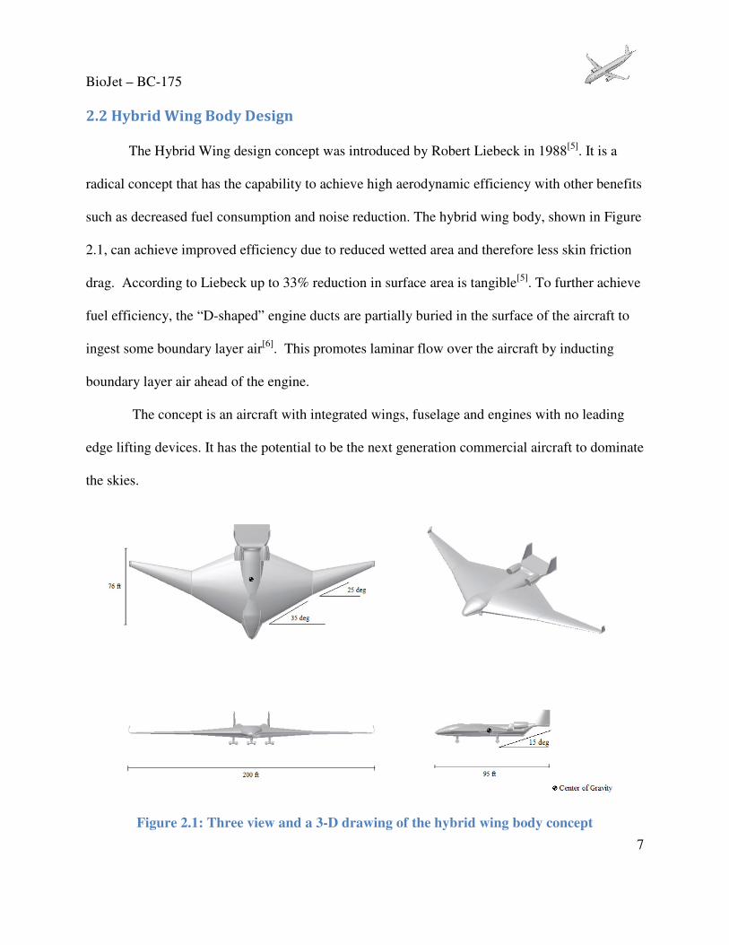
2.2 Hybrid Wing Body Design
The Hybrid Wing design concept was introduced by Robert Liebeck in 1988[5]. It is a
radical concept that has the capability to achieve high aerodynamic efficiency with other benefits
such as decreased fuel consumption and noise reduction. The hybrid wing body, shown in Figure
2.1, can achieve improved efficiency due to reduced wetted area and therefore less skin friction
drag. According to Liebeck up to 33% reduction in surface area is tangible[5]. To further achieve
fuel efficiency, the “D-shaped” engine ducts are partially buried in the surface of the aircraft to
ingest some boundary layer air[6]. This promotes laminar flow over the aircraft by inducting
boundary layer air ahead of the engine.
The concept is an aircraft with integrated wings, fuselage and engines with no leading
edge lifting devices. It has the potential to be the next generation commercial aircraft to dominate
the skies.
Figure 2.1: Three view and a 3-D drawing of the hybrid wing body concept

BioJet – BC-175
8
In addition to being very efficient, the hybrid wing body is also capable of noise
reduction. The engines are placed on the upper surface of the aircraft where the forward engine
noise is shielded and the rear engine noise can be neglected because it is not reflected from the
lower surface of the wing. Also, the airframe noise is reduced due to the fact that there are no
slotted trailing edge flaps [7].
The main concerns for a hybrid wing body are stability and control, and structures. Due
to lack of horizontal tails and aft CG position the aircraft is longitudinally unstable. An advanced
digital flight control technology may solve this problem. Another challenge comes from
structures, where the hybrid wing body requires a unique approach to the pressurization of the
aircraft. Due to unconventional shape of the fuselage, a cylindrical approach is futile.
By comparing the advantages and disadvantages of the hybrid wing body to other designs
(Table 2.2), it was proposed to go onto the final selection. HWB design is able to easily achieve
the 25% increase L/D ratio along with a significant reduction in noise. The large increase in L/D
is possible due to a single large lifting surface.
Table 2.2: Pro-Con Chart for HWB
Pro Con
• Can achieve max efficiency due to reduction of surface area
• Reduction in fuel consumption and emissions
• Less noise
• More room for fuel and luggage
• Comfortable space for passengers
• Non-conventional fuselage shape
• Structure complexity
• Difficulty manufacturing
• Increase in cost due to large span
• Stability and control complexity
Using Raymer[8] we estimated initial aerodynamic characteristics of the design. These
estimations were used to calculate the final T/W vs. W/S graph, presented in Figure 2.2. The
area bounded by the constraint curves is feasible and the design point is indicated by the star.

BioJet – BC-175
9
Figure 2.2: BWB Sizing optimization.
From this chart a design point was chosen where the wing loading was set at 72 lb/ft2 and the
thrust to weight was at .285.
The final sizing for the HWB design is based on the output from Nicolai’s program[9].
The inputs used for the sizing program came from several different sources. The weight
constants used were from the general transport values given in the read me file provided with
Nicolai. The values of cruise Mach number, fixed weight, and the mission radius came from the
RFP. The aspect ratio was taken from the other sizing data. The specific fuel consumption
comes from the engine data for the current engines being used. Once all the data was entered,
the program was run. The program gave a maximum takeoff weight of 138,000 lbs and a fuel
weight of 34,000 lbs.
0
0.1
0.2
0.3
0.4
0.5
0.6
0.7
0.8
0 20 40 60 80 100 120 140
T/W
W/S, lb/ft2
Cruise
Landing
Missed Approach
Takeoff
Second Segment Climb

BioJet – BC-175
10
2.3 Tube and Wing Concept
The Tube and Wing is similar to the design that is used in current aircraft. This concept is
based on the same wing-fuselage configuration as the conventional aircraft. However, it employs
the use of a V-tail and a C-winglet. The V-tail is used to decrease flow interference between the
normal horizontal and vertical surface of conventional tail configuration. This will also help
reduce weight by reducing the number of needed control surfaces. The use of a C-winglet is an
innovative take on the boxed winglet utilized in early concepts. Figure 2.3 is a picture of an
early BWB concept with C-winglet.
Figure 2.3: BWB with C-wing[10]
The purpose of the C-winglet is similar to that of the winglet originally developed by Richard
Whitcomb. Planar wings tend to have high pressure airflow from the bottom circulate around the
wing tip to the low pressure region above the wing. This generates a loss of lift at the wingtip.
The purpose of the winglet is to block the three-dimensional effects of high pressure flow around
the wingtips. The span-wise loading distribution is represented by the Oswald efficiency factor.
A planar wing with an elliptical loading distribution has an efficiency of 1. Through the use of

BioJet – BC-175
11
winglets and C-winglets, the efficiency can greatly increase. Figure 2.4 shows the span
efficiency for various wing shapes[10].
Figure 2.4: Comparison of Span Efficiency for Various Wing Types[10]
The C-winglet is depicted with an efficiency of 1.45 while a full box wing has an efficiency of
about 1.46. It can achieve an efficiency near that of a box wing without the additional weight.
This is the main motivation. However, some negatives such as the additional root wing bending
moment and aeroelastic effects can lead to increased structural weight[10].
The pros and cons of the Tube and Wing design are presented below in Table 2.3. Many
positives are results of the design’s similarity to current aircraft. Besides the C-wing and the V-
tail, many of the current aircraft technologies and analysis can be applied to this design. Its
similarity with Tube and Wing aircraft will also help reduce manufacturing costs as current Tube
and Wing assembly facilities will be able to accommodate this design. Another important
consideration is aircraft family expansion. If additional larger or smaller models are desired the
seating capacity can be changed by simply manipulating the fuselage length. However, the
design is weak in some areas. The thin wings reduce storage capacity for high lift systems and

BioJet – BC-175
12
biofuels when compared to the previous mentioned design. The V-tail's ruddervators combine
the pitch and yaw forces. This significantly increases the difficulty of stability analysis. The C-
wing's thin complex shape can lead to aeroelastic issues such as flutter and increased structural
weight due to generation of a large bending moment. Most of these cons can be overcome using
advanced control systems making this concept a viable replacement for current aircraft.
Table 2.3: Pros-Cons of Tube and Wing Design
Pros Cons
• Optimized use of fuselage area
• Simple, familiar Fuselage and Wing design
• Low manufacturing costs
• Simple Family Expansion • C-wing greatly increases span efficiency
• V-tail creates combined rudder and elevator forces
• C-wing has issues with aeroelasticity and bending moment generation
The Tube and Wing design is shown below in Figure 2.5. With a span of 121 feet and
length of 130 feet, the concept is very similar to the current Boeing 737 and A320. The
maximum span was limited assuming the new aircraft will be more accessible if it fit into the
same gates as comparable aircraft. The fuselage length was designed to provide the space for the
RFP's required 175 passengers.

BioJet – BC-175
13
Figure 2.5: Tube and Wing Design
To create the T/W vs. W/S graph the same method was used as with the HWB. This is
shown in figure 2.6 and indicates the aircraft design point.

BioJet – BC-175
14
Figure 2.6: Tube and Wing Sizing Optimization
The design point for this concept was selected at a W/S of 129 lb/ft2 and a T/W of 0.26. This is
used to determine the thrust and wing area needed to fly all parts of the aircraft's mission profile.
To determine the maximum takeoff weight for the Tube and Wing aircraft, Nicolai’s
sizing program was again used[9]. The inputs used were gathered in the same manner as for the
Hybrid Wing Body. The program gave a maximum takeoff weight of 122,500 lbs and a fuel
weight of 25,500 lbs.

BioJet – BC-175
15
2.4 Design Selection
Both the HWB and the Tube and Wing concepts where compared to determine the better
final design. These designs are also compared to the Boeing 737 in an effort to insure the final
design is an improvement over the replaced aircraft. Table 2.4 is a decision matrix used for
comparison.
Table 2.4: Design Selection Decision Matrix
The table above compares the HWB, the Tube and Wing, and the Boeing 737 using five
comparison factors: weight, aerodynamics, stability and control, manufacturing cost, and biofuel
storage capacity. Each of the criteria are assigned a weight. The aircraft are scored based on their
ability to minimize weight, maximize aerodynamic efficiency, maximize stability and control,
minimize manufacturing cost and to maximize biofuel storage capacity. The aircraft are given a
value between 0 and 1 for each of the factors with 1 as the best. The aircraft scores are computed
by summing the scores and multiplying by the factor weight. According to the table, the Tube
and Wing is the best design solution and exhibits sufficient improvements over the current
Boeing 737.
Through in-depth analysis of the Tube and Wing concept, it was determined that the C-
wing was not necessary to obtain the performance specifications required by the RFP. Thus, the
design will utilize standard blended winglets instead. From Figure 2.4, the winglet achieves an
Oswald efficiency factor near that of the C-wing of about 1.41. The design is also simpler

BioJet – BC-175
16
allowing more straight forward analysis methods. Table 2.8 below discusses the advantages and
disadvantages of the final design when compared to the former concepts.
Table 2.5: Pros and Cons of Final Tube and Wing Design
Pros Cons
• Optimized use of fuselage area
• Simple, familiar Fuselage and Wing design
• Low manufacturing costs
• Simple Family Expansion
• Winglets greatly increases span efficiency
• V-tail creates combined rudder and elevator forces
A constraint diagram was created for the final design using methods previously
discussed.
Figure 2.7: Final Design Constraint Diagram
The design point is at a T/W of .42 and a 103 lb/ft2. This is subject to change depending on the
engine selection.
0
0.1
0.2
0.3
0.4
0.5
0.6
0.7
0.8
0 20 40 60 80 100 120 140
T/W
W/S, lb/ft2
Cruise
Landing
Missed Approach
Second Segment Climb
Takeoff

BioJet – BC-175
17
3. Biofuels
In an effort to design the most environmentally friendly aircraft, the fuel type becomes
very important. A significant requirement of the RFP includes the use of biofuels as a
replacement to current petroleum-based fuels. Biofuels consist of any fuel sources derived from
plant matter. Biofuels can be produced on large farming facilities reducing the dependence on
foreign fossil fuels. The growing of these plants consumes carbon dioxide which is a major
greenhouse gas. However, many biofuels such as Ethanol and Soybean-based Biodiesel require
large amounts of land to grow [11]. Most biofuels also have lower densities and energy contents
than current jet fuels such as Jet-A resulting in larger fuel tanks.
3.1 Biofuel Selection
A trade study was performed in order to select the optimum fuel source for the BC-175.
Table 3.1 is a comparison of biofuels with hydrogen, Jet-A, and Fischer-Tropsch Fuel (a
synthetic petroleum derived from coal). The comparison includes density, energy content, energy
density, and energy per Boeing 737-400 tank.

BioJet – BC-175
18
Table 3.1: Energy Content Comparison
Fuel Density (lb/ft3)
Energy Content (Btu/lb*103)
Energy Density (Btu/ft3)
Energy per Flight (Btu*106)
for 737-400 Tank Size
Jet A 50.2 18.6 1280 770
FT-Gasoline 49.8 18.6 1280 760
Biodiesel(Methyl Ester)
55.4 16.1 1230 730
Algae 50.0 17.2 1190 700
Ethanol 49.3 13.4 910 540
Methanol(Liquid) 49.6 9.8 670 400
Soybeans 48.1 9.0 600 360
Hydrogen (Liquid) 4.4 61.0 370 220
Methane(Gas) 3.5 23.9 110 68
Hydrogen (Gas) 0.051 61 0.43 0.26
Results show that the current Jet-A, petroleum-based fuel, has the highest energy content. The
next closest biofuel is algae. With a tank energy approximately 9% less than Jet-A, fuel tanks
only need to be slightly larger for the same aircraft. This means little modification to current
aircraft and concepts. In addition, Algae can be grown in many places and the amount of land
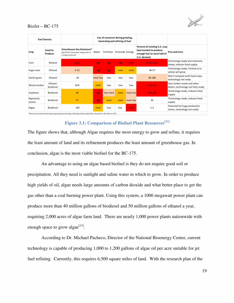
required can be decreased as algae can be grown vertically. Figure 3.1 is a comparison of
different plant resources and their land and growing requirements[12].
BioJet – BC-175
19
Figure 3.1: Comparison of Biofuel Plant Resources[12]
The figure shows that, although Algae requires the most energy to grow and refine, it requires
the least amount of land and its refinement produces the least amount of greenhouse gas. In
conclusion, algae is the most viable biofuel for the BC-175.
An advantage to using an algae based biofuel is they do not require good soil or
precipitation. All they need is sunlight and saline water in which to grow. In order to produce
high yields of oil, algae needs large amounts of carbon dioxide and what better place to get the
gas other than a coal burning power plant. Using this system, a 1000 megawatt power plant can
produce more than 40 million gallons of biodiesel and 50 million gallons of ethanol a year,
requiring 2,000 acres of algae farm land. There are nearly 1,000 power plants nationwide with
enough space to grow algae[13].
According to Dr. Michael Pacheco, Director of the National Bioenergy Center, current
technology is capable of producing 1,000 to 1,200 gallons of algae oil per acre suitable for jet
fuel refining. Currently, this requires 6,500 square miles of land. With the research plan of the
CropUsed to
Produce
Greenhouse Gas Emissions* (Kg of C02 created per mega joule of
energy produced)
Water Fertilizer Pesticide Energy
Percent of existing U.S. crop
land needed to produce
enough fuel to meet half of
U.S. demand
Pros and Cons
Corn Ethanol 81-85 high high high high 157%-262%Technology ready and relatively
cheap, reduces food supply
Sugar cane Ethanol 4-12 high high med med 46-57Technology ready, limited as to
where will grow
Switch grass Ethanol -24 med-low low low low 60-108Won't compete with food crops,
technology not ready
Wood residueEthanol,
biodieselN/A med low low low 150-250
Uses timber waste and other
debris, technology not fully ready
Soybeans Biodiesel 49 high low-med med med-low 180-240Technology ready, reduces food
supply
Rapeseed,
canolaBiodiesel 37 high med med med-low 30
Technology ready, reduces food
supply
Algae Biodiesel -183 med low low high 1-2Potential for huge production
levels, technology not ready
Use of resources during growing,
harvesting and refining of fuelFuel Sources
*Emissions produced during the growing, harvesting, refining and burning of fuel. Gasoline is 94, diesel is 83.

BioJet – BC-175
20
National Renewable Energy Laboratory the land required will shrink to 830 square miles and
produce as much as 10 to 15 thousand gallons per acre as shown in the figure below relating to
state of Arizona.
Figure 3.2: Algae Oil Needed for Five Billion Gal/yr Jet Fuel[14]
Current algae cost is around 30 dollars per gallon. This extremely high price is due to the
large amounts of energy required to create the fuel. However, some companies such as Solix
project cost reductions of around 90% in the near future [15]. This will greatly encourage Algae
use. In early 2010, Continental Airways flight 516 used a 50-50 blend of Jet-A and biofuels
which included 600 gallons of algae fuel[16]. The flight was successful proving the viability of
algae as an aviation fuel in the future.

BioJet – BC-175
21
4. AERODYNAMICS
The RFP requires a 25% increase in lift-to-drag ratio over the current aircraft in this
passenger class. Achieving this requires a wing design that has both low frictional and wave drag
characteristics. Minimizing weight through composite structural design allows for a standard
wing loading on an otherwise smaller area wing, when compared to aircraft such as the 737 and
A320. The resultant increase in aspect ratio provides the prescribed increase in lift-to-drag ratio,
while a supercritical airfoil section reduces the wave drag penalty at the transonic cruise speed of
Mach 0.8. These traits paired with a set of tip devices that further increase L/D and span loading
efficiency prove the feasibility of operation on biofuels.
4.1Wing Design
To fit into the unmodified terminal gates that accept the 737 and A320, the wing has a
similar span of 117 feet. The wing area was selected by adopting a design wing loading (W/S)
that is similar to current aircraft in this class. At roughly 100 pounds per square foot based on the
initial cruise weight of 120,453 pounds the wing area as designed is 1181 square feet giving a
thrust-to-weight (T/W) of 0.46 at this flight condition. To achieve the maximum possible extent
of natural laminar flow, the leading edge sweep is designed to keep the transitional Reynolds
number beyond that which the wing experiences during all normal flight conditions. As greatly
swept wings promote spanwise disturbance growth and separation, leading edge sweep was
chosen to be 17 degrees using Figure 4.1 below, from Braslow[17]. According to the figure, this
sweep gives a transitional Reynolds number of roughly 22 million corresponding to a
characteristic length of 14.4 feet. This length is well beyond the chord location where the adverse

BioJet – BC-175
22
pressure gradient will cause transition. A root chord of 17 feet was chosen in correspondence
with the wing area to give a historically similar taper ratio of 0.235 and a tip chord of 4 feet.
Figure 4.1: Experimental data, transitional Reynolds number with leading edge sweep
Modified from Braslow[17]
Airfoil selection is a crucial part of this design considering the challenges of flying more
efficiently at transonic cruise velocities than the 737 and A320. Wave drag can severely inhibit
the performance of a wing in this flight regime, therefore the wing section chosen is designed to
greatly reduce this risk. The use of a supercritical section over the entire wing delays sonic
conditions and raises the drag divergence Mach number until beyond the cruise velocity. These
airfoil shapes produce lift more evenly across the chord length of their upper surface as
compared to standard airfoils. On a non-supercritical section the favorable pressure gradient
around the first quarter of the chord length is stronger, produces the majority of the lift and
would likely accelerate the flow to sonic conditions at the cruise condition of Mach 0.8. The type
of airfoil used has an extended and weaker pressure gradient that delays shocks from forming on
the wing and therefore reduces the wave drag. Figure 4.2 below, shows the supercritical airfoil
Transitional Reynolds Number 22x106
BC-175
17⁰ LE Sweep

BioJet – BC-175
23
section that has been selected. The NASA SC(2)-0412 airfoil has a 12% thickness-to-chord and
1.3% camber.
Figure 4.2: NASA SC(2)-0412
[18]
The airfoil was analyzed using XFoil at the takeoff velocity of Mach 0.2 at sea level. The results
shown in Figure 4.3 include the data as computed and data corrected by a factor of 22 percent.
The correction was implemented from an article by Peter Garison[19] where he compares XFoil
estimations to actual flight test data. The corrected airfoil prediction shows a maximum lift
coefficient of 1.82 at 16.1 degrees angle of attack.
Figure 4.3: XFoil lift coefficient versus angle of attack computation and correction for
NASA SC(2)-0412
The modified Korn equation from Mason[20] with simple sweep theory is used to estimate
the drag divergence Mach number based on the selected design parameters:
��� = �����− (� �)⁄
����− �������� (4.1)
-0.5
0.0
0.5
1.0
1.5
2.0
2.5
-5 5 15 25
Cl
Angle of Attack, deg
Xfoil corrected, Mach 0.2 @ Sea Level
Computed
Corrected

BioJet – BC-175
24
where ���, ��, � �� , Λ and �� represent drag divergence Mach number, lift coefficient, thickness
to chord ratio, leading edge sweep and airfoil technology factor, respectively. The technology
factor will remain a constant 0.95 representing a supercritical section.
Based on the modified Korn equation and the empirically-derived shape of the drag
rise[20], the critical Mach number is 0.69 and the drag divergence Mach number is 0.79. This
calculation was based on the cruise condition lift coefficient at maximum takeoff weight. As the
plane will actually be flying lighter than in this conservative estimate, it will require less lift and
have higher actual drag divergence and critical Mach numbers. Designing the drag divergence
Mach number to be right at the cruise velocity in this fashion insures wave drag will not be an
issue.
The winglet plays a large role in meeting RFP requirements. The advantages include
nearly 6% decrease in fuel consumption by producing a forward thrust component and thus
reducing the total drag. This also reduces emissions and noise since the engine is run at lower
thrust settings. The winglet design geometry is adopted from those that have been retrofitted on
most 737’s that fly today. At 10 feet tall and 2.25 feet wide they increase span loading efficiency
e, to 1.2 at the cruise condition, as computed by a Trepz plane induced drag calculation.
4.2 High Lift Devices
The BC-175 needs to achieve a lift coefficient of 2.1, corresponding to the landing
conditions discussed in Section 7.5 Landing. High lift devices will be required as the maximum
clean wing lift coefficient is computed as 1.38 at 11 degrees angle of attack, limited by the tail
scrape angle. Using a high lift analysis from Raymer[8] and the maximum lift coefficient, double
slotted flaps are used over half of the reference area on the inboard sections. The required

BioJet – BC-175
25
extension in chord length is 15% for the landing condition equating to a 56% flap extension. The
high lift device configuration is illustrated in Figure 4.4, below.
Figure 4.4: High Lift Device Configuration
The conservative design will allow for landing at altitudes higher than sea level while still having
space further outboard for aileron placement. Landing and takeoff are designed to be achieved
without leading edge devices because they often cause transitional effects to the boundary layer
even when retracted due to small gaps in the section. To achieve maximum laminar flow across
the wing, the double slotted Fowler style flap is the sole high lift device used on this aircraft. By
sufficiently increasing wing area and airfoil camber using these high lift devices, the wing
loading is low enough to achieve the takeoff and landing requirements.
4.3 Drag Analysis
Since the BC-175 will be flying at transonic velocities, wave drag is considered along
with the standard parasitic and induced drags. A program, TBWwrapper, an Aerodynamic
Estimation Framework for Air Vehicle Conceptual Design written by Gur[21], was used for
Aileron Flaps
Thrust Gate
Engine Nacelle
Fuselage

BioJet – BC-175
26
further aerodynamic analysis. The program considers multiple drag estimations and design
conditions as defined by the user. As it considers all parts of the aircraft and their orientation
with one another, an estimation of interference drag is produced. A complete consideration of the
drag breakdown is shown below in Figure 4.5 from Gur[21]
Figure 4.5: Drag Breakdown
[21]
Each of these drag contributions is estimated and summed together for the drag build up at
takeoff, cruise and landing in Figure 4.6 below.
Figure 4.6: Drag Buildup
Lift coefficients with lift-to-drag ratio at each cruise altitude and the cruise velocity are shown in
Figure 4.7 below. The two different data sets represent weight conditions at initial and final
0.00
0.02
0.04
0.06
0.08
0.10
0.12
Cruise Takeoff Landing
CD
Induced
Wave
Interference
Form+Friction
CDf
&
CDform
CDi CDint CDw CD
Takeoff 0.0120 0.0925 0.0021 0.0000 0.1066
Cruise 0.0117 0.0084 0.0009 0.0054 0.0270
Landing 0.0120 0.1020 0.0022 0.0000 0.1162

BioJet – BC-175
27
cruise. Early in cruise, the maximum L/D is 21.6 which slightly falls to 21.5 before descent.
After a short time in cruise, the L/Dmax is achieved at the cruise altitude as shown by the slight
peak in the initial cruise weight data below.
Figure 4.7: Trimmed cruise lift-to-drag ratio analysis 0.8 M, 41000 feet
Trim drag must also be considered for cruising flight. An analysis that shows how drag on the
BC-175 changes with the additional drag accompanied by the trim setting is shown below, to the
right, in Figure 4.8. On the left of the figure, a range for cruising lift coefficients is also shown.
35kft
41kft
19.0
19.5
20.0
20.5
21.0
21.5
22.0
0.0 0.2 0.4 0.6 0.8
L/D
CL
Initial
Final

BioJet – BC-175
28
Figure 4.8: Cruise Trim Drag Analysis 0.8 M, 41000 feet
5. Propulsion
Based on the criteria given by the RFP, it was decided that turbofan engines be used for
our concepts. There were three different types of engines to choose from: propfan, turbojet and
turbofan. A propfan engine was not selected because of its inefficiency in noise level which was
part of the RFP requirement. A turbojet engine creates lots of noise and it is very inefficient
when flying in subsonic range. Therefore a turbofan engine is more feasible for our requirement.
Various turbofan engines were compared as shown below in Table 5.1. Out of these, the
PW1000G was chosen for our concept based on the specification below. The PW1000G was
chosen for its efficiency and the new technologies associated with it which help meet the RFP
requirements.
0.00.10.20.30.40.50.60.70.80.9
0.00 0.01 0.02 0.03 0.04 0.05
CL
CD
Trimmed Flight, 0.8M@41kft
L/Dmax=21.8
Cruising Range
0.00.10.20.30.40.50.60.70.80.9
0 1 2 3 4 5 6
CL
∆CD*10-4
(Drag Counts)
Trim Drag

BioJet – BC-175
29
Table 5.1: Various engine specifications. [22]
ENGINE CFM56-5A1 used
in A320-211/-311 CFM56-5B3
used in A321 CFM56-5C4
used in A340 PW2037
used in B757 PW1000G used in
Irkut MS-21
Thrust(lb) 25000 32000 34000 36600 28000
SFC 0.33 0.36 0.33 0.335 0.29
Airflow(lb/s) 852 956 1065 1210 -
BPR 6 5.4 6.4 5.8 12 Thrust_cruise
(lb) 5000 5840 7100 6500 -
SFC_cruise 0.596 0.545 0.545 0.582 -
Fan dia. (in) 68.3 68.3 72 78.5 74 Dry weight
(lb) 4995 5250 5700 7185 -
The PW1000G uses a gear box to decouple and slow down the rotation speed of the fan
from that of the low-pressure spool which allows both the fan and the low pressure turbine to run
at a more efficient speed. The fan is rotating 30% slower than a conventional turbofan which
means that the blade-tip speed is subsonic and there is no adverse shock wave effect.
The slower rotation speed of the fan and the large fan diameter gives two advantages: up
to a 14% improvement in fuel efficiency (compared to current turbofan engine) and lower noise
levels. The bypass ratio is so high that the cold bypass air mixes with the hot exhaust air
covering the noise produced by the exhaust air. Also, the shock wave noise is eliminated due to
subsonic rotation speed of the fan-blade tips. To further reduce noise levels, PW1000G will
have a cut-off nacelle design.
In order to cut down on NOx level, the combustor in PW1000G uses latest TALON-X
(Technology for Advanced Low NOx) design. As the engine heats up and cools down, the inner-
lining panels expand and contract independently reducing wear and therefore the amount of

BioJet – BC-175
30
maintenance required on the engine. Using TALON-X, PW1000G is able to reduce NOx
emission by 50% compared to CAEP 6[23].
PW1000G promises reduction in operating cost, reduction in fuel burn by 14%, 50%
lower noise level compared to current turbofan engines and fewer moving parts which means
lower maintenance cost [24]. Although the current maximum thrust required for our aircraft is
28,000 lbs per engine, therefore we can use the Pratt and Whitney engines that will be used on
Irkut MS-21 which produces 25,000-32,000 lbs of thrust.
To calculate the thrust available at different altitude for PW1000G the following equation was used:
�� = �� ∗ " ##$%& ∗ '
($%( (5.1)
where �� is thrust at sea level, )� is pressure at sea level and �� is the temperature at sea
level[25]. Using the equation above, a thrust vs. altitude graph was created as shown in Figure 5.1
below.
Figure 5.1: Thrust Available vs. Altitude for PW1000G
0
5000
10000
15000
20000
25000
30000
0 5000 10000 15000 20000 25000 30000 35000 40000 45000 50000
Th
rust
(lb
)
Altitude (ft)

BioJet – BC-175
31
6. Weights
6.1 Final Weights
The weight of the BC-175 was determined with the estimation methods from Jan
Roskam[26]. Each component was estimated using the equations provided in the text, unless
actual values were available. As some of these equations are dependent on the TOGW, an
iterative process was used to calculate the final TOGW. The initial weight for the iteration was
calculated using Nicolai's aircraft sizing algorithm[8]. The weight values from the iteration
process are shown in Table 6.1.
Table 6.1: Iteration of TOGW for the BC-175
Iteration Process (lbs)
Nicolai Initial Iteration 1 Iteration 2 Iteration 3 Iteration 4 Iteration 5
TOGW 122589 124652 124964 125011 125018 125019 Wempty 60018 56577 56889 56936 56943 56944 Zero fuel 91514 93577 93889 93936 93943 93944
This process was run for a total of five iterations and led to the final weight value of each
component in the TOGW, shown in Table 6.2.

BioJet – BC-175
32
Table 6.2: Aircraft Component Weight Breakdown
Component Weight
(lbs)
Location
(ft)
Moment
(ft-lbs)
Payload 37000 57 2109000
Fuel Weight 31075 50 1553750
Wing 11814 54 637956
Tail 408 116 47355
Fuselage 7025 55 383561
Nacelle 4160 50 208000
Main Gear 4142 57 236103
Nose Gear 773 12 9279
Engine Weight 10000 50 500000
Fuel System 590 53 31253
Propulsion System 464 50 23192
Flight Control System 1600 67 107210
Hydraulic and Pneumatic 1000 62 62009
Electrical System 1550 50 77475
Instruments Electronics Avionics 1869 18 33642
AC, Anti-icing 3429 70 240021
Oxygen System 240 50 12000
APU 875 116 101514
Furnishings 7005 57 399282
TOGW 125019 54.17 6772602
Wempty 56944 54.65 3111721
Zero fuel 93944 55.55 5218852
Table 6.3 compares these weights to those of existing aircraft.
Table 6.3: Weight comparison of BC-175
BC-175 737-700 A320-200
TOGW 125019 154,500 170,000
Wempty 56944 84,100 93,000
Zero Fuel 93944 110,035 119,293
This table shows that our aircraft is significantly lighter than current aircraft.
BioJet – BC-175
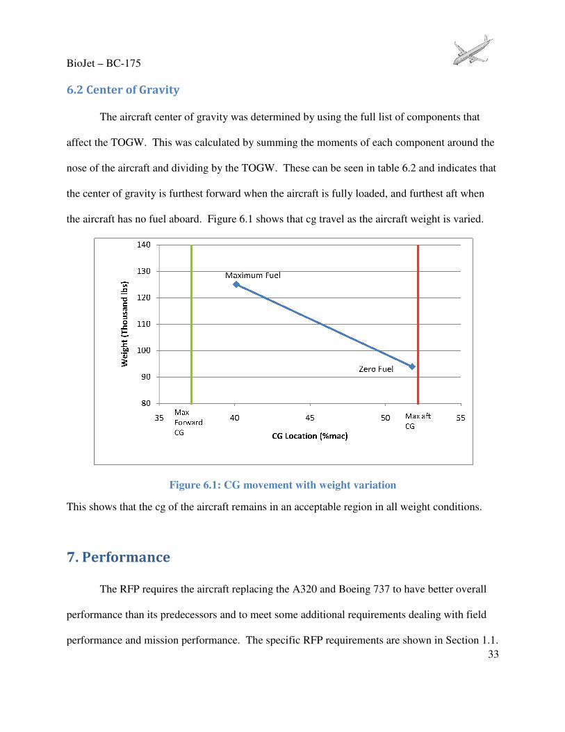
6.2 Center of Gravity
The aircraft center of gravity was determined by using the full list of components that
affect the TOGW. This was calculated by
nose of the aircraft and dividing by the TOG
the center of gravity is furthest forward when the aircraft is fully loaded, and furthest aft when
the aircraft has no fuel aboard. Figure
Figure 6.1: CG movement with weight variation
This shows that the cg of the aircraft remains in a
7. Performance
The RFP requires the aircraft replacing the A320 and Boeing 737 to have better overall
performance than its predecessors and to meet some additional requirements dealing with field
performance and mission performance. The specific RFP requirements are shown in Section 1.1.
The aircraft center of gravity was determined by using the full list of components that
the TOGW. This was calculated by summing the moments of each component around the
by the TOGW. These can be seen in table 6.2 and indicate
is furthest forward when the aircraft is fully loaded, and furthest aft when
Figure 6.1 shows that cg travel as the aircraft weight is
Figure 6.1: CG movement with weight variation
This shows that the cg of the aircraft remains in an acceptable region in all weight conditions.
The RFP requires the aircraft replacing the A320 and Boeing 737 to have better overall
erformance than its predecessors and to meet some additional requirements dealing with field
performance and mission performance. The specific RFP requirements are shown in Section 1.1.
33
The aircraft center of gravity was determined by using the full list of components that
summing the moments of each component around the
.2 and indicates that
is furthest forward when the aircraft is fully loaded, and furthest aft when
.1 shows that cg travel as the aircraft weight is varied.
acceptable region in all weight conditions.
The RFP requires the aircraft replacing the A320 and Boeing 737 to have better overall
erformance than its predecessors and to meet some additional requirements dealing with field
performance and mission performance. The specific RFP requirements are shown in Section 1.1.

BioJet – BC-175
34
The BC-175 was analyzed using formulas from Raymer[8], Anderson[27], and
Marchman[28] to ensure each performance qualification was met. Specifically, the mission flight
was broken into takeoff, climbing flight, cruise, descent, and landing for analysis. Within each
section general performance was evaluated along with the parameters specified within the RFP.
An overall mission profile was then constructed merging the analysis of each individual flight
segment into a composite.
7.1 Takeoff
The main takeoff parameter used to gauge performance in an aircraft destined for
operation under FAR Part 121[30] is balanced field length. Balanced field length is the total
takeoff distance including obstacle clearance when an engine fails at the decision point, the
speed at which, upon an engine failure, the aircraft can either brake to a halt or continue the
takeoff in the same total distance. If the engine fails before decision speed, the pilot can easily
brake to a halt. If the engine fails after decision speed, the pilot must complete the takeoff[8].
The obstacle height included for a commercial aircraft is 35 ft[30]. To meet the RFP, the BC-175
must have a maximum balanced field length of 8,200 ft. The balanced field length was analyzed
at density altitudes from zero to 5,000 ft to provide more information for various airport
elevations. The results of the Balanced Field Length analysis are shown below.

BioJet – BC-175
35
Table 7.1: Takeoff Performance for BC-175
Takeoff Performance
Density Altitude (ft) BFL (ft) RFP Req. - 8200ft Ground Roll (ft) Takeoff Speed (knots) CL
0 6177 OK 4056 137 2
1000 6586 OK 4297 139 2
2000 7021 OK 4551 141 2
3000 7495 OK 4826 143 2
4000 8002 OK 5119 145 2
5000 8200 OK 5440 147 2
Each takeoff case assumes the runway to be dry asphalt and the aircraft is at maximum takeoff
ground weight. It does not have to be a standard temperature day since the altitudes given are
density altitudes. In actual operations, the BC-175 can obtain a substantial performance gain
when operating at reduced gross weights. The takeoff thrust can be reduced, reducing the
amount of fuel required so the takeoff distances remain the same as when carrying the maximum
weight. This will conserve fuel on takeoff since less thrust is being used. However, the pilot
will still be able to use the full thrust available in case of an emergency were more thrust is
required. The BC-175 meets the balanced field length requirement set forth by the RFP.
7.2 Climbing Flight
The only climbing flight parameter required by the RFP is climb to the initial cruise
altitude. The RFP requires the aircraft to reach an altitude of 35,000 ft without the use of step
climbing. The BC-175 is equipped with two PW1000G engines which provide 28,000 lbs of
thrust at sea level. The climbing characteristics for the BC-175 are shown below.

BioJet – BC-175
36
Table 7.2: Climbing Flight Performance for BC-175
Climbing Flight
Density Altitude (ft)
Climb Angle (deg)
Rate of Climb (fpm)
Indicated Airspeed (knots)
0 - 10000 5.0 2207 250
10000 - 35000 4.5 2196 275
35000 - 41000 2.6 1257 275
The first climb from 0 to 10,000 ft is constrained by the FAA regulation which implements a
speed limit of 250 knots under 10,000 ft. The second climb stage is designed around the best
rate of climb. According to Aircraft Performance Engineering[31] and Optimizing Jet Transport
Efficiency[32], airliners typically climb at a speed slightly faster than the speed for best rate of
climb. This allows the aircraft to travel a farther distance on the same amount of fuel and lose
only a slight rate of climb. For the BC-175 that speed is 275 knots and it results in a normal
climb rate of about 2,000 fpm. To complete the climb to 41,000 ft, the same indicated airspeed
is used. However, the higher altitude results in lower excess thrust to climb with. With less
thrust available a lower climb angle is required to maintain the same indicated airspeed. This
results in a lower climb rate.
Although some aircraft require the use of a level segment at an initial cruise altitude to
reduce weight through fuel burn before having the climb capability of reaching a final cruise
altitude (step climb), the BC-175 has sufficient power available to climb directly to 41,000 ft
after a maximum gross weight takeoff without the need for an intermediate level off. Additional
information about the climb profile of the BC-175 is provided in Section 7.6.

BioJet – BC-175
37
7.3 Range
The RFP sets out three significant requirements for the cruise portion of the mission
profile. These are
• Cruise altitude selected must be between FL 35,000 ft and FL 41,000 ft.
• Cruise speed must be at least Mach 0.8 but is limited to a maximum of Mach 0.83
or 340 KCAS (knots calibrated airspeed), and
• The aircraft must have a nominal operational range of 1,200 nautical miles and a
maximum operational range of 3,500 nautical miles.
The cruise data for the BC-175 is shown below.
Table 7.3: Cruise Performance for BC-175
Cruise Values Not Including Climbing and Descending Range
Density Altitude (ft) Mach Speed (knots) Speed (KCAS) Speed Check L/D Range (nmi)
35000 0.8 461 255 OK 20.67 3221
36000 0.8 459 249 OK 20.97 3253
37000 0.8 459 244 OK 21.23 3291
38000 0.8 459 238 OK 21.44 3323
39000 0.8 459 232 OK 21.58 3345
40000 0.8 459 227 OK 21.63 3353
41000 0.8 459 222 OK 21.74 3370
The values above are shown with the aircraft at gross weight. The chart below shows the thrust
required to meet the required airspeed numbers for flight at 41,000 ft for the BC-175 and
demonstrates that the required thrust is available to meet the RFP requirements.

BioJet – BC-175
38
Figure 7.1: Thrust Required at 41,000 ft for BC-175
This graph shows the BC-175 will be able to maintain level flight at a cruise altitude of 41,000 ft.
It also shows the excess thrust that enables the aircraft to climb directly to 41,000 ft instead of
having to step climb after a significant fuel burn.
The BC-175 has been designed to optimize performance in the altitudes required by the
RFP. This optimization provides for efficient flight and significant range profiles for the BC-
175. The following charts display the specific range of the BC-175 at different Mach numbers
and altitudes.
0
5,000
10,000
15,000
20,000
25,000
0.0 0.2 0.4 0.6 0.8 1.0
Th
rust
(lb
s)
Mach Number
Thrust Required 41000ft
Thrust Required
Thrust Available
Cruise Speed
Stall Speed

BioJet – BC-175
39
Figure 7.2: Specific Range including drag rise for BC-175
This graph takes into account the drag rise caused by the increased wave drag encountered by
local supersonic flow over a wing when still flying at subsonic speeds. This increase in drag
occurs when flying at speeds at or above the critical Mach number for an aircraft. Sweeping a
wing will increase the critical Mach number and thereby delay the onset of the drag rise. The
critical Mach number for the BC-175 is 0.68.
Examining the graph shows the design of the BC-175 has been optimized for the flight
conditions set by the RFP. The flight point should optimally occur slightly to the right of the
peak of the graph. By having the point to the right of the peak, the aircraft will be able to fly at a
higher speed with only a minimal loss in specific range. This is more efficient than flying slower
0.10
0.12
0.14
0.16
0.18
0.20
0.22
0.24
0.60 0.65 0.70 0.75 0.80 0.85
sr(n
m/l
b)
Mach Number
35000 ft 36000 ft 37000 ft 38000 ft
39000 ft 40000 ft 41000 ft Flight Point

BioJet – BC-175
40
at a slightly higher specific range. The chosen flight conditions of 41,000 ft and Mach 0.8 occur
at the optimum location. This shows the aircraft will be flying at the most favorable conditions.
Since the line graph can sometimes be hard to read, a contour plot of the specific range is shown
below.
Figure 7.3: Contour Plot of Specific Range for BC-175
The contour plot shows the flight conditions of 41,000 ft and Mach 0.8 (represented by
the black diamond) will be the most efficient. This is again because the flight point should be
just slightly right of the area for best specific range and cruise speed. These graphs show the
BC-175 is designed optimally for the conditions set forth by the RFP.

BioJet – BC-175
41
The analysis shown above demonstrates that the BC-175 can cruise at FL 41,000 ft at
Mach 0.8 and have a range of 3,500 nautical miles. Therefore, the BC-175 passes all three RFP
conditions for cruising flight.
7.4 Descent
There are no specific requirements in the RFP for descending flight. The descent
segment was determined using requirements from Notes on Airline Climb and Descent[29]. The
two constraints on descent are the cabin pressure cannot descend faster than 300 ft/min and the
aircraft generally descends at the flight idle engine setting. The BC-175 cabin is pressurized to
8,000 ft which requires about 27 minutes minimum for the descent. The descent from 41,000 ft
will take about 32 minutes as shown in Section 6.6 which meets the minimum required time.
Flight idle for the aircraft is 60% of maximum thrust available. This flight idle setting will allow
for the aircraft to decrease its speed as it descends with the assistance of speed brakes.
7.5 Landing
The only landing requirement set forth by the RFP is the aircraft must have a landing
speed lower than 140 KCAS. Along with landing speed, the FAR field lengths were also
determined to provide an idea of the required landing distance. The FAR field length is defined
as the total approach distance over a 35 ft obstacle and the total ground roll required to stop
multiplied by 1.666 to allow for pilot technique[8]. Similar to takeoff, the landing performance
values were evaluated at density altitudes of zero to 5,000 ft. The analysis is shown below.

BioJet – BC-175
42
Table 7.4: Landing Performance for BC-175
Landing Performance
Density Altitude (ft) Landing Speed (knots) RFP Req. < 140kts Total Ground Roll (ft) Total Approach (ft) FAR Field Length (ft) CL
0 125 OK 2900 3778 6293 2.1
1000 127 OK 2935 3818 6361 2.1
2000 128 OK 2973 3863 6435 2.1
3000 130 OK 3014 3910 6514 2.1
4000 132 OK 3058 3961 6599 2.1
5000 134 OK 3104 4014 6688 2.1
Each case assumes the runway is dry asphalt and uses the landing weight determined
from the mission profile in Section 7.6 of 99,200 lbs. This is the maximum landing weight
which is the maximum zero fuel weight plus fuel reserves for maximum range. The landing
analysis conducted assumes using only landing gear brakes to bring the aircraft to a stop. Also it
is assumed that there is a three second period between when the aircraft touches down and when
the brakes are applied. Several features including reverse thrust, auto brakes, and auto spoiler
deployment were not considered in these calculations. If these were to be included, the
operational performance would be significantly better than calculated. It should be noted that the
landing distance is less than the balanced field length. Therefore, the aircraft can safely arrive at
any airport that it is capable of departing. The BC-175 meets the landing speed requirements set
by the RFP.
7.6 Mission Profile
By combining the previous sections a complete mission profile for the BC-175 can be
constructed. The mission profile, which details each flight stage for a maximum range flight, is
shown below.

BioJet – BC-175
43
Mission Profile
Mission Segment Mach Altitude (ft) L/D Time (min) Fuel (lbs) Distance (nmi)
1. Taxi/Takeoff 0 - 0.23 SL - 15.0 2041 0
2. First Climb Stage 0.23 - 0.37 0 - 10000 - 4.5 551 19
3. Second Climb Stage 0.37 - 0.48 10000 - 35000 - 12.1 1472 55
4. Third Climb Stage 0.48 35000 - 41000 - 3.8 409 17
5. Acceleration to Cruise 0.48 - 0.8 41000 - 1.0 93 6
6. Cruise 0.8 41000 21.74 442.2 18219 3370
7. Descent 0.8 - 0.25 41000 - 1500 - 31.6 2509 74
8. Landing 0.25 - 0 1500 - SL - 5.0 680 0
Totals 515.3 25974 3541
Missed Approach
9. Climb 0 - 0.37 0 - 15000 - 6.8 826 28
10. Cruise 0.37 - 0.4 15000 27.73 28.1 825 117
11. Descent 0.4 - 0.25 15000 - 1500 - 27.0 765 56
12. Landing 0.25 - 0 1500 - 0 - 5.0 680 0
Totals 66.9 3097 202
Figure 7.4: Mission Profile for BC-175

BioJet – BC-175
44
Segments 1 through 8 represent a regular flight for maximum range. For shorter flights the
cruise segment will be shortened. Segments 9 through 12 represent a missed approach and if
needed a cruise to another airport 200 nautical miles away.
The entire mission uses 29,070 lbs of fuel and the BC-175 carries 31,070 lbs of fuel.
This leaves a small window for changing the mission profile if required. While many portions of
this profile can be modified, this outlines a regular flight for the BC-175.
7.7 Comparison of Performance
The BC-175 satisfies every performance requirement established by the RFP however,
the BC-175 does not qualify as a legitimate replacement for the existing aircraft unless it out
performs its predecessors. A chart below compares the performance of the BC-175 to the A320
and the Boeing 737-800.
Table 7.5: Comparison of Performance Characteristics[3][4]
Boeing 737-800 Airbus A320 BC-175
Max Take-off Weight (lbs) 174200 170000 124500
Balanced Field Length (ft) 8000-8300 6900 6200
Service Ceiling (ft) 41000 39000 41000
Cruise Speed (Mach/mph) .78/511 0.78/511 0.8/530
Max Range (nmi) 3060 3200 3500
L/D Max 19 20 27
Landing Speed (knots) 150 134 125
This chart shows the BC-175 is a significant step up from both the Boeing 737 and the A320.
The most notable comparison is the lift to drag ratios in which the BC-175 is required to have a
25% increase over both the Boeing 737 and A320. Also, the BC-175 is significantly lighter than
both the Boeing 737 and the A320. The above data shows the BC-175 will be a viable
replacement for the Boeing 737 and the A320.

BioJet – BC-175
45
The RFP requirements for performance and the BC-175’s capabilities are shown below.
Table 7.6: RFP Performance Requirements for BC-175
RFP Requirements
RFP BC-175 Check
Balanced Field Length - 8200ft 6200 GOOD
Cruise Altitude FL 350 – 410 FL 410 GOOD
Range (nmi) Nominal 1200, Max 3500 3500 GOOD
Landing Speed < 140 KCAS 125 GOOD
L/D Max 23+ 27 GOOD
The BC-175 fulfills all of the performance requirements of the RFP and will be able to replace
the Boeing 737 and the A320 as a superior short and long range carrier.
8. Structures and Materials
The BC-175 is constructed with an assortment of materials combined with efficient
placement of load bearing structural supports to accommodate the requirements given in the RFP
as well as reduce overall weight and cost. A special consideration for this project is the
integration of improved composite materials that not only reduce weight but provide for strong
structural components. In addition, the advantage to reducing overall weight can provide for
more emphasis on implementation of newer technologies in control surfaces and other systems.
8.1 Material Comparison
An important aspect to fully understand before discussing structural design is the
overview of the different materials considered for the aircraft. Considering the importance of
integration of composite materials one must understand the advantages and disadvantages when

BioJet – BC-175
46
compared to previously used materials. Table 8.1 below shows a simple comparison of the
different materials considered for the two designs. The two CFRPs shown in the Table below are
developed by Toray Carbon Fiber. They utilize new technology such as "applied thermoplastic
particles" which toughens the material and helps stop crack propagation[33]. The T1000
composite has the highest tensile strength in the world and was designed specifically for pressure
vessel applications such as a aircraft cabin[33].
Table 8.1: Material Comparison[34][35][36][37][38]
Alum.
2024-T0
Alum.
7075-0
AISI 1050
Steel Alloy
AMS 4914
Tit. Alloy
CFRP
T800-S
CFRP
T1000
Cost ($/lb) ~1.50 ~1.50 ~7.00 ~40.00 ~30.00 ~50.00
Density (lb/ft3) 170 175 490 300 75 112
Yield Strength (ksi) 11 21 180 110 415 ~420
Tensile Strength (ksi) 32 40 220 140 430 440
Therm Cond.
(BTUIT /(hr*ft*oF)
~110 ~75 ~17 ~5 ~20 ~19
8.2 V-N Diagrams
To determine the materials to use to account for the larger structural loading cases, a V-n
diagram is essential. At low speeds the maximum load factor is constrained by aircraft maximum
lift coefficient. At higher speeds the maneuver load factor may be restricted as specified by FAR
Part 25.337[30]. This gives a maximum load factor of about 2.5 and a minimum of about -1.0[30].
Gust loads are also added to show how wind gusts effect the loads on the aircraft surfaces[39].
Figure 8.1 below shows the V-n diagram for the BC-175.

BioJet – BC-175
47
Figure 8.1: V-n Diagram
8.3 Wing Design
Wing structure design is important to maximize the efficiency of an aircraft's
performance. For the BC-175, a standard setup with two spar with a wing box is utilized. The
two spars, I-beam in design, will be placed at 15% chord aft of the leading edge and 34% chord
forward of the trailing edge flaps. This placement is chosen to ensure structural stability as well
as maximize volume inside the wing for fuel tank space. AMS 4914 Titanium Alloy is chosen
for the spars due to its low weight, high strength and somewhat lower cost shown in Table 8.1.
The spar accommodates for vertical deflections in flight and on the ground. The overall bending
moment and ultimate strength of the spar is determined by the limits given on the V-n diagram,
Figure 8.1, above. The wing box, which includes the ribs and the stringers, is constructed out of
T800-S composite. Because of its incredibly light weight, high strength, and thermo
conductivity properties, T800-S is a perfect fit to accommodate the structural demands needed
with the wing box. A few other benefits include no fatigue due to repeated stress, no crack
-1.5
-1
-0.5
0
0.5
1
1.5
2
2.5
3
0 100 200 300 400
Loa
d F
act
or
(n)
EAS (knots)
V-n Diagram
Gust
Loads
Series4
Series5

BioJet – BC-175
48
propagation, and no corrosion[40]. The composite also requires little to no maintenance which
will reduce the lifetime cost of the aircraft.
8.4 Control Surfaces
Control surfaces are a perfect place to utilize composite materials and were one of the
first components of aircraft in which composites were used[40]. There are many benefits of using
composite materials on control surfaces. Considering that much of the maintenance that aircrafts
undergo is due to the stress on the control surfaces and their supporting structures, applying
composites are very beneficial. Due to low corrosive properties and absence of fatigue potential,
lifetime maintenance on control surfaces drops dramatically. Because of the low weight aspect of
composites the controls surfaces are lighter which decreases the need for stronger structural
support to hold them. T800-S is used for the skin, and a combination of the composite with
Aluminum 2024 is used to construct the structure box. Aluminum is used because of its high
thermal conductivity which is useful for de-icing and relatively low weight. Titanium alloy is
used at where the control surfaces touch the spars on the wing and tail to support the structural
loads.
8.5 Skin and Pressure Vessel
The most significant change in aircraft structural design in the past five years is the
complete implementation of composite materials to the skin of the aircraft. In previous years it
was determined the composites were not strong enough to account for the pressure difference
required in the cabin. With the production of strong composites such as T1000, this is now
possible. With the BC-175 , T1000 is utilized for the skin as well at the forward and aft pressure

BioJet – BC-175
49
vessel caps. Because of its incredible tensile strength, the skin can be very thin and still provide
the strength needed to hold aerodynamic shape and accommodate for pressure differences at any
altitude[34]. This application dramatically reduces the weight and required lifetime maintenance
of the aircraft. For the BC-175 the cabin will be pressurized to 8,000 feet. At the intersection
points of the wing and tail, Titanium alloy is used to provide the structural support.
8.6 Engine Nacelle
The engine nacelle is another component in which composite materials have been used
for decades[40]. The skin of the nacelle is constructed with T1000 composite because of the local
exposure to heat from the engine as well as the load from the thrust. Titanium alloy is used at the
connection to the engine pylon to handle the large point load applied at that location.
8.7 Miscellaneous
A few other important components are explained in the following paragraph. First, the
nose cone of the BC-175 is constructed with KFRP with Aluminum 2024. This is to allow the
radar to work appropriately and to prevent damage in the event of a collision with small particles
or birds[41]. The landing gear is housed in a pod when retracted which is constructed with T800-S
composite.
8.8 Manufacturing and Maintenance
A large portion of the cost of a new aircraft is incorporating the associated manufacturing
costs. Considering the relative size and design of the aircraft, manufacturing facility costs will
be significantly cheaper because the size and equipment used in existing facilities can be utilized.
Many of the main structural components of the design are similar to existing aircraft which will
BioJet – BC-175
50
also reduce the cost of manufacturing. The integration of composite materials will call of an
increase in cost due to the relatively higher material cost. However, these expenses are
countered by the waste-free production and molding of these materials. When composite
material is molded to a new shape, all excess material is saved and reused. Another significant
fact is the overall decrease in parts needed when composites are used as replacements. For
example, when Airbus built their vertical fin box out of composite materials, they reduced the
overall fastener count from 2,076 to only 95 parts[40]. This saves manufacturing, labor, and
maintenance. Aluminum and titanium molding and carving facilities are expensive and require
routine maintenance but are essential to both designs.
The lifetime costs of the BC-175 will be significantly cheaper than other modern aircraft.
As discussed in previous sections, the extensive implementation of composite materials reduces
the need for regular maintenance everywhere its applied. It is estimated that "associated costs
with maintenance and operation will be at least two to three times greater than initial purchase
values"[41]. Although, it is important to note if a composite structure is damaged the repair cost
can be up to twice of what it would be with regular metallic structures[41]. However, the
technology required to effectively repair composite damage should be sufficient in the next few
years.
8.9 Overview and Cad Drawings
The other basic structural components are described in the following section. Bulk head
placement, along with ribs, stringers, and longerons are determined through proven structural
design. Due to the usage of strong composites such as T800-S and T1000 on the skin of the
aircraft, a semi-monocoque construction is used. This transfers loads from the wing through the

BioJet – BC-175
51
skin which is then absorbed by the stronger load bearing members such as the bulk heads and
spars. Longerons and stringers help support the longitudinal loads and bulkheads help support
the transverse loads on the fuselage. Larger bulkheads are placed near where the wing attaches
to the fuselage to absorb the forces and moments created by the aerodynamic forces on the wing.
Figure 8.2 below shows the basic layout of the aircraft.
Figure 8.2: Structural Diagram
The ribs of the fuselage, designed with Aluminum 2024-T0, are spaced about three feet
about the whole way down the aircraft. Larger ribs are placed more frequently, about every foot
and a half, where the wing connects to the fuselage. These are constructed with Aluminum 7075-
0. Bulkheads are placed forward of the first entrance, two are placed where the wing starts and
ends on the fuselage, and one is placed aft of the rear entrance. Longerons are placed at 0°, 90°,

BioJet – BC-175
52
180°, and 270° around the fuselage. Bulkheads, longerons, and stringers are all constructed with
Aluminum 2024-T0. In the two tails there are small spars located forward of the control surface
at about 36% chord and ribs are placed every two feet. In the wing, the ribs are placed every foot
and a half. These ribs are shaped to provide enough volume for the fuel tanks.
9. Stability and Control
The BC-175 is a class III aircraft which satisfies the requirements set by the RFP and FAR. The
design utilizes a V-tail to reduce wetted area as well as traditional control surfaces to ensure safe
operation under all conditions. Analysis to determine the neutral point, the control surface sizing, and
the dynamic flight qualities was done using various methods and programs. These programs included
Tornado Vortex Lattice Method (VLM)[42], LDstab (Lateral Directional Stability)[43], and a VPI-NASA Excel
spreadsheet[44]. Tornado was used to determine the stability derivatives, the control derivatives, the
static margin and the neutral point. LDstab was used for some preliminary engine out analysis, while the
VPI-NASA Excel spreadsheet was used for the final engine out analysis. The VPI-NASA Excel spreadsheet
was developed by Virginia Tech and was also used for aileron and ruddervator sizing calculations.
9.1 Tail Sizing
Two tail configurations were considered for the BC-175: a V-Tail configuration and a
conventional tail. Both configurations were analyzed and sized for the minimum static margin,
engine out criteria, and nose wheel lift off. Ultimately the V-tail was found to reduce tail area by
87.1 square feet (21.0%) over the conventional tail. The static margin was evaluated at cruise and
maximum altitude. The engine out criteria was evaluated under takeoff at sea level conditions.

BioJet – BC-175
53
The V-tail has a root chord of 11.0 feet, a tip chord of 8.0 feet, and a total area of 323.7 square
feet. It has a dihedral angle of 42.76° and is 73.4 feet from the wing apex to the tail apex.
The engine out condition requires that the available yawing moment coefficient exceeds
the yawing moment coefficient required to maintain steady flight with one failed engine at
1.2Vstall as required under FAR 25.149[30]. The remaining engine must be able to maintain full
thrust of 28,000 lbs without the bank angle exceeding 5°. The aforementioned VPI-NASA Excel
spreadsheet was used to complete the analysis. The engine out parameters are shown in Table
9.1.
Table 9.1: Engine Out Analysis
Engine Out Analysis
Β 2.55
Φ 4
∆a 1.24
∆r 20
Cnavail 0.0489
Cnrequired 0.0299
9.2 Static Margin
The minimum static margin was found to be 10% using the Tornado Vortex Lattice
Method Matlab code. The Tornado model can be seen in Figure 9.1. The center of gravity
location ranges from 39.5% MAC when the aircraft is fully loaded to 51.3% MAC at the zero
fuel weight.

BioJet – BC-175
54
Figure 9.1: Tornado Model
9.3 Control Surface Sizing
The BC-175 utilizes ailerons, spoilers, and ruddervators to complete all necessary in
flight maneuvers. The ruddervators are sized to meet engine out criteria as well as nose wheel lift
off during takeoff. The ruddervators are 35% of the tail chord and have a total area of 113.3
square feet. The ruddervators are capable of lifting the nose off the ground at a speed lower than
the calculated lift-off speed. Section 4.2.7.3 of MIL-STD-1797 states that at 0.9Vmin the aircraft
must be able to achieve the pitch attitude required for take-off at Vmin for dry runways. The BC-
175 is capable of achieving a pitch angle of 11.5° at 0.9Vmin,which exceeds the 11° pitch angle
required for take-off at Vmin. Figure 9.2 shows the relationship between the pitch angle and the
lift-off velocity.
-20
0
20
40
60
80
-50
0
50
Aircraft body x-coordinate
Aircraft body y-coordinate
MAC
ref point
c.g.

BioJet – BC-175
55
Figure 9.2: Pitch Angle vs. Velocity Required for Nose-Wheel Lift-off
The ailerons were sized for a Level 1 flight rating as defined by MIL-F 8785B roll
performance specifications. The requirement is that the plane must be able to roll 30° in 1.5
seconds. The BC-175 takes 1.00 seconds to roll 30°. Figure 9.3 shows the roll response of the
BC-175. The ailerons run to the base of the winglets taking up 40% of the wing span and 25% of
the wing chord. All control surfaces were sized using stability derivatives found by the Tornado
VLM program. Tables 9.2 and 9.3 show the stability and control derivatives.

BioJet – BC-175
56
Figure 9.3: Roll Performance Capability with Sized Ailerons
Table 9.2: Longitudinal Stability Derivatives
Derivative BC-175
Cmα -1.722
Cmq -30.333
CLα 5.165
CLq 7.282
CLdr 0.297
CDdr 0.001
Cmdr -1.905

BioJet – BC-175
57
Table 9.3: Lateral-Directional Stability Derivatives
Derivative BC-175
Clβ 0.174
Clp -0.385
Clr 0.08
Cnβ -0.144
Cnp 0.042
Cnr -0.156
Cyβ -0.479
Cyp 0.319
Cyr -0.321
Cyda -0.096
Clda 0.196
Cnda 0.005
Cydr -0.233
Cldr 0.034
Cndr -0.131
9.4 Dynamic Analysis
Dynamic analysis was done using the approximate methods of estimation from
Roskam[45] with derivatives found from the Tornado VLM. Evaluation of the dynamic qualities
was done for the cruise case at a Mach number of 0.8 and at an altitude of 41,000 feet on a
standard day. The dynamic qualities for the phugoid, short period, and dutch roll modes were
compared with the requirements for MIL-STD Class I Category B flight. Table 9.4 compares the
Class I requirements with the dynamic values estimated for the BC-175.
The preliminary analysis reveals that both the short period mode and the dutch roll mode
are under-damped. To bring these modes up to a Level 1 flight rating, the BC-175 is equipped
with a flight control system consisting of feedback gain for both the pitch rate and the yaw rate.

BioJet – BC-175
58
By implementing such a flight control system it is possible to bring the damping ratios of the
short period and dutch roll modes up to Level 1 requirements.
Table 9.4: BC-175 Dynamic Modes and Level 1 Requirements (no control system)
Damping Frequency
Requirement BC-175 Requirement BC-175
Phugoid ξPH > 0.04 0.042 NA NA
Short Period 0.3 < ξsp < 2.0 0.253 0.8rad/s < ωnsp < 2 1.565
Dutch Roll ξD > 0.19 0.065 ωnD > 0.4 1.202
10. Systems
The BC-175 will incorporate advanced systems in an effort to improve flight
performance and efficiency. Many different systems come to play when designing an aircraft;
however, there are some especially significant systems to discuss.
10.1 Aircraft Cabin Layout
The aircraft cabin is designed to RFP and FAA specifications. The aircraft seats 177
passengers in a single class configuration and the cabin must be at least 12.5 feet wide and 7.25
feet tall. Current Boeing 737 and A320 configurations use a single aisle with 6 seats per row.
This configuration will be used for the BC-175. The cabin sizing was determined using a code
located on the Stanford website[46]. The figure below shows the passenger cabin cross-section.

BioJet – BC-175
Figure 10
The seats are 20 inches wide compared to the standard 17.2 inches add
The aisle width was increased to
passenger mobility during cabin travel or emergency evacuations
a point on one seat to the same point on the next seat
general location of crew stations, galleys, lavator
Figure 10.1: Cabin Cross-section
The seats are 20 inches wide compared to the standard 17.2 inches adding to passenger comfort.
The aisle width was increased to 24 inches compared to the standard 18 inches increas
passenger mobility during cabin travel or emergency evacuations. The pitch, or the
a point on one seat to the same point on the next seat, is 32 inches. The figure below shows the
general location of crew stations, galleys, lavatories, and emergency exits.
59
to passenger comfort.
increasing
. The pitch, or the distance from
The figure below shows the

BioJet – BC-175
Figure
This layout insures passenger comfort and safety. There are two general galley locations with
one located at the front and rear of the cabin. There are also four
the aircraft and one handicap-accessible lavatory at the front of the aircraft. For passenger safety,
there are numerous emergency exits including three
cabin over the wing Type III exit doors. This exceeds th
emergency exits[30]. The crew station is
have personal folding seats in each galley.
Figure 10.2: Cabin Arrangement
This layout insures passenger comfort and safety. There are two general galley locations with
r of the cabin. There are also four standard lavatories at the rear o
accessible lavatory at the front of the aircraft. For passenger safety,
rous emergency exits including three floor level Type A exit doors and
cabin over the wing Type III exit doors. This exceeds the FAR 25.807 requirement for
. The crew station is located in the white section above. Flight attendants
have personal folding seats in each galley.
60
This layout insures passenger comfort and safety. There are two general galley locations with
standard lavatories at the rear of
accessible lavatory at the front of the aircraft. For passenger safety,
floor level Type A exit doors and four mid-
e FAR 25.807 requirement for
located in the white section above. Flight attendants

BioJet – BC-175
61
There are a number of environmental systems to consider when designing an aircraft
cabin. B/E Aerospace provided many of the cabin systems used on the Boeing 787. These were
used as a basis for the selection of cabin systems for the BC-175.
The B/E Aerospace seating systems are a low cost, lightweight, and safe solution. A three
seat group is pictured below.
Figure 10.3: B/E Aerospace Three Seat Cluster[47]
The seats make use of lightweight, strong aluminum alloys, and a fabric suspension system to
reduce weight while maintaining durability.
Another important system to consider is the oxygen system. B/E Aerospace produces an
innovative oxygen delivery mechanism called the Pulse Passenger Oxygen System[48]. The
oxygen is stored in a pressurized tank and activated only when required. It is dispersed to the
passenger based on their breathing patterns helping preserve oxygen. This system, pictured
below, is powered off during normal operating conditions resulting in zero energy consumption.

BioJet – BC-175
62
Figure 10.4: B/E Aerospace Pulse Oxygen Delivery System[48]
B/E Aerospace also produces a similar portable system for individual cases of oxygen
deprivation. The small single lever design allows simple operation and only requires three AA
batteries.
The BC-175 utilizes LED, or light emitting diode systems rely on large quantities of
small bulbs to provide versatile lighting schemes. With the incorporation of B/E Aerospace's
Mood Lighting System[49], interior cabin lighting will be able to achieve twice the brightness of
current fluorescent systems with a choice of 16.7 million colors. Lighting color variation can be
used to calm passengers, helping to relieve symptoms of jet lag. LED's also consume less energy
compared to current lighting systems. The figure below pictures a cabin with the Mood Lighting
System.

BioJet – BC-175
63
Figure 10.5: Boeing 787 Mood Lighting System[49]
10.2 Cockpit Layout
Modern aircraft are utilizing more digital technologies and replacing or replicating many
analog buttons and instruments. An example is the Rockwell Collins MFD-2912 digital display
pictured below.
Figure 10.6: Rockwell-Collins MFD 2912 Digital Display[50]
This display can be used to view any aircraft data from control deflections to three dimensional
weather patterns. Five of these will be incorporated into the BC-175 cockpit. Each pilot will have
two monitors and a center console display allowing the monitoring of many different flight

BioJet – BC-175
64
systems simultaneously. In addition, the Rockwell Collins HGS-4000 will be installed[51]. The
HGS or heads-up guidance system is a small transparent display that is situated between the pilot
and the windshield. It displays vital information in the pilot’s forward field of view. The figure
below shows a Boeing 787 cockpit with the HGS and a similar five monitor set-up.
Figure 10.7: Boeing 787 Cockpit[52]
The following figure is a two-dimensional profile of the main instrument panel and center
console. The majority of the analog controls have been incorporated into digital display system.

BioJet – BC-175
65
Figure 10.8: BC-175 Cockpit Layout[53]
Controls such as throttle, autopilot, and deicing are in an optimum position for either pilot to
monitor. The overhead instrument panel consists of storage area for manuals and remaining
emergency, lighting, and cabin warning controls.
10.3 Flight Control Systems
The BC-175 control system is comprised of many new improvements over current
aircraft. Current aircraft like the Boeing 737 or A320 use mostly hydraulics for control surface
deflection. For the BC-175 electro-mechanical systems are used to deflect control surfaces using
electric motors. These are lighter and require less maintenance than hydraulic controls. This
results in an overall improvement in control reliability.
Other improvements include a new system for control signal transfer. As a modern
adaptation of the fly-by-wire systems, fly-by-light relies on the same principles with enhanced

BioJet – BC-175
66
performance. Fly-by-wire is used in current aircraft where wires transmit signals from the flight
controls, through the flight control computer, to the actuators. Wires can only transfer one way
signals so an abundance of wires are necessary. Fly-by-light systems use fiber optic cables to
transmit multiple signals through the same cable. The signals in a fly-by-light system are
transferred by light waves which travel faster than electrical signals. Each cable is connected to
an inline signal concentrator to condense thousands of electrical signals for optical conversion.
Each conversion also produces redundant signals to ensure system integrity. Although an
electrical to optical signal converter is required, the overall savings in weight are significant.
Recent testing of fly-by-light was completed by Gulfstream, a subsidiary of General
Dynamics[54]. The system replaced a wire bundle with only four fiber optic cables. By utilizing
this system, the BC-175 will be safer and lighter than aircraft using fly-by-wire.
10.4 Electrical Systems
The electrical system of an aircraft provides electricity to all other aircraft systems.
Several large components of the electrical infrastructure are discussed below.
The auxiliary power unit or APU is a central part of the modern aircraft. The APU is a
small engine often used to power preflight systems and to start main aircraft engines. It can be
used to supplement control power during flight or operate aircraft emergency systems during
engine failure. In an effort to reduce system complexity, the BC-175 utilizes an APU system
similar to that of the Boeing 787, using electrical controls rather than the common additional
pneumatic load compressor.
The APU is a small turbine engine located in the tail of the BC-175. The APU will have
an upper fuselage inlet and an exhaust out the tail. There will be two variable frequency electric

BioJet – BC-175
67
generators attached to the APU to be used for starting engines and electric power generation. The
generators will also have to generate more electricity throughout the flight than the Boeing 737
or A 320 as a no bleed air system, the Hamilton Sundstrand APS5000, will be used. This APU
produces about 1,100 horsepower. This will be used with the 6 electrical generators( two for
each engine and two for the APU) which are rated at 225kVA. The system will use a 115/200v,
400Hz alternating current[55]. With comparable equipment to the 787, the system should produce
around 1 megawatt of electrical power.
10.5 Pressurization
Most current aircraft such as the 737 and the A320 extract air from the engines to power
pressurization. This air is pulled from the compressor stage of the engine where the air
temperature is higher. This means current pressurized turbojet aircraft require intercooling to
lower the temperature of the air. This results in additional weight for air tubing and a reduction in
engine efficiency. To avoid these disadvantages, the BC-175 will use electric pressurization like
the Boeing 787. Although there will be additional weight due to a larger APU and electric
compressors, a safer, more reliable electrical system can be used.
In electric pressurization, air is extracted from the atmosphere and compressed through
electronic compressors which are supplied power from the generators. The main difference in the
power scheme to current aircraft is that the system is extracting direct shaft power from the
turbine and creating electrical power rather than pneumatic power. This reduces system
complexity. By using an electric system, the same goals are achieved as with pneumatic power in
a less complex fashion[56].

BioJet – BC-175
68
10.6 Deicing System
Current aircraft such as the Boeing 737 and Airbus A320 utilize heated exhaust from the
turbofan engines to melt ice. However, this can adversely affect the flow over the surface as well
as reduce the engine's performance.
New deicing technologies such as electric heating mats can be used without bleed air. A
company named GKN Aerospace has developed a heating mat to be used on various new
aircraft[53]. The mat is a composite laminate made of layers of carbon and glass fibers with a
metal conductive layer in the middle. The heat comes from passing an electric current through
the metal layer. A picture of the system is shown below.
Figure 10.9: GKN Deicing Heat Mat[57]
Temperatures can reach anywhere from 45-70 degrees Fahrenheit and consumes about 45-75
kilowatts. The BC-175 will use the mats for deicing and for anti-icing to prevent any ice
formation during flight.

BioJet – BC-175
69
10.7 Fuel Systems
The BC-175 fuel system is optimized to store Algae bio-fuels. To store this fuel larger
fuel tanks are needed. Algae fuel requires about 1.08 times the tank volume compared to Jet-A.
The fuel tanks are designed to utilize about fifty percent of the wing chord. The figure below is
an airfoil with the approximate fuel tank in blue.
Figure 10.10: Wing Tank Location
Using Algae and the fuel weight determined in sizing, the volume needed is about 680 cubic feet.
However, the FARs[30] require a two percent increase in volume to account for varying fuel
density. Thus, the target volume for max range is about 694 cubic feet. Due to the landing gear,
the tank starts at the fuselage and continues 40 feet into the wing. The wing tanks store about 287
cubic feet of fuel. An additional wing-box tank is needed for the remaining 407 cubic feet. The
following figure shows the wing and fuselage fuel tank locations.

BioJet – BC-175
70
Figure 10.11: Fuel Tank Locations
10.8 Landing Gear
The landing gear for the BC-175 is designed to allow the aircraft to pitch during takeoff
and landing and to support the aircraft. The tricycle configuration will be used which consists of
two main gear and a nose gear. The main landing gear usually appear beneath the wing but are
located a certain distance behind the total aircraft center of gravity. This distance is found using
Raymer[8]. Raymer states that the angle between the vertical at the landing gear and the CG
location must be around 15 degrees to allow the aircraft to pitch during takeoff. This angle
allows for sufficient rotation. Using this method the angle to the main gear was set at 14.3
degrees. This means the landing gear is 56.6 feet aft of fuselage station zero, 2.7 feet aft of the
CG.

BioJet – BC-175
71
The tailscrape angle is the angle between the ground and the aircraft bottom from the
main gear. This must be larger than the required angle of attack for takeoff and landing. This is
shown on the figure below.
Figure 10.12: BC-175 Right Side View
Another consideration is the rollover or overturn angle. This is the angle between the CG
and the ground at the main landing gear. Raymer states that the angle must be less than 63
degrees for tricycle landing gear. The rollover angle is about 50 degrees for the BC-175 as
pictured below.
Figure 10.13: BC-175 Front View
Further analysis was done to determine the approximate tire sizes. Using Raymer's
statistical tire sizing in Chapter 11, the load on the gear and the coefficients for transport aircraft
were determined. When satisfying the angle requirements, it was found that the nose gear should
hold about 7.5 percent of the TOGW and the main gear split the rest. This results in about 9,375

BioJet – BC-175
72
pounds-force on the nose gear and about 57,812 pounds-force on each main gear. Each gear has
two wheels. The approximate size of the main gear tires for the BC-175 is a 42 X 15, where the
first term is the diameter in inches and the second is the width in inches. The nearest
manufactured size is the 46X16. The approximate size of the nose gear tires is 25 X 8.8. The
nearest manufactured size is 30 X 8.8. All tires are rated for 225 miles per hours, well above the
max takeoff or landing velocities.
10.9 Noise Reduction
The RFP requests a reduction in noise emissions along with an overall increase in
efficiency and performance. When considering noise, the common transport aircraft produce the
most noise during takeoff and landing. The largest contributors to noise are the engine, high-lift
devices, landing gear and the airframe. There are numerous technologies to reduce noise.
The turbofan engines used on most jet transports are the leading noise producers. Thus,
there is significant research being done to reduce engine noise through more efficient engines
and nacelles. Goodrich Aerospace has designed a new more aerodynamic nacelle to be used on
the Boeing 787.

BioJet – BC-175
73
Figure 10.14: Boeing 787 with Goodrich Nacelle[58]
Figure 10.14 shows a constant paint scheme over the nacelle keeping the surface as smooth as
possible to insure laminar flow is maintained. The most noticeable features are the trailing edge
chevrons. The chevrons, constructed of a shape memory alloy, deform during flight with
temperature change. The spiked design generates trailing edge vortices to help mix the flow over
the nacelle with the high temperature engine exhaust helping to reduce noise[59].
Landing gear noise production comes mainly from the awkward non-streamlined
structure. Air simply collides with the gear, strut, and wheel sections causing flow detachment,
resulting in noise. Thus, the best way to reduce noise is reduce separation or production of
turbulence through the use of fairings. Fairings are effectively caps that cover intricate high noise
sections of the landing gear system helping reduce noise. An experiment was performed on an
A340 landing gear with fairings finding that up to a 3 decibel reduction can be achieved[60].
Pictures of the test configuration are shown below. The top photo is the standard main landing
gear and the bottom photo is the main gear with fairings over the wheel connection and the leg-
door connection.

BioJet – BC-175
74
Figure 10.15: A340 Main Landing Gear Noise Test Configuration[60]
10.10 Airport Systems
The BC-175 will use an Algae-based Biodiesel. Because the fuel is not widely used, a
new system will have to be considered. However, since the Algae-based Biodiesel is similar to
Jet-A in density and energy content there will not be significant changes. The fuel system will
remain relatively unchanged except for methods of fuel distinction. Since a new type of fuel is
being introduced, it will have to be distinguished from other fuels so minor changes such as new
fuel nozzles and labeling will be used. Fuel nozzles for Algae tanker trucks and aircraft will be
shaped differently as to not fit into other aircraft. This will reduce refueling error and help make
the change to Algae simpler. The actual fuel transport process will remain the same; below is a
schematic of current fueling schemes.

BioJet – BC-175
75
Figure 10.16: Airport Fueling System[61]
The figure shows a system including an onsite fuel storage tank, direct-to-plane fueling (DTP),
pump and filtration (PFT), remote dispensing (RDS), and refueling truck loading (TLO).
The BC-175 fuel system is based on current fuel systems with slight modifications like larger
aircraft tank sizes for the storage of Algae-based biodiesel. From the fuel tank sizing, the BC-175
will carry 4,550 US gallons. Current Jet-A airport tankers store up to 5000 gallons and have
pump rates up to 600 gallons per minute. This will result in common refueling times of about 7.5
minutes.
Figure 10.17: 5,000 Gallon Jet-A Refueler with 300 GPM Pump System[62]

BioJet – BC-175
76
10.11 Cargo
The RFP requires at least 1240 ft3 of cargo space for passenger luggage. This includes
carry-on and luggage storage below the deck. For carry-on storage compartments, the maximum
standard size is 9 by 14 by 22 inches or about 1.605 ft3. Thus for 175 passengers plus an
additional free space, the carry-on compartments will store about 300 ft3. The below the deck
storage will be about 1000 ft3. The below the deck storage compartments are located below the
front entrance to the wing root and below the rear exit to the wing trailing edge. Loading will
start at the entrance storage area. The aircraft will be able to use cargo containers or manual bulk
loading. Cargo containers allow quicker loading times decreasing cost. The cargo containers to
be used are the LD-3-45 pictured below.
Figure 10.18: LD3-45 Cargo Container[63]
Each container stores about 124 ft3 of luggage. Therefore, a maximum of ten containers are
needed if no onboard storage is used. This will take up about 50 ft of the fuselage length for
cargo leaving additional space for other systems. Specifically, cargo will be loaded starting 15

BioJet – BC-175
77
feet aft of the nose to about 40 ft aft of the nose. The remaining half of the containers will be
loaded from behind the wing at about 65 ft to 90 ft.
11. Cost
The cost of this aircraft must be competitive with current aircraft to be profitable. These
costs consist of the flyaway and life cycle costs that a potential buyer would consider before
deciding to purchase an aircraft.
11.1 Life Cycle Cost
The life cycle cost of a program consists of the costs of research, development, testing
and evaluation (RDTE), acquisition, operation and support, and the disposal of the airplane.
Aircraft disposal consists of 10% of this total cost. The cost was estimated using Roskam’s cost
estimating method from Airplane Design Part VIII[64].
11.2 Research, Development, Testing, and Evaluation
RDTE covers the planning, design, development and testing of the aircraft. The dollar
rates used in the RDTE phase are shown in table 11.1. In this period, 104 million man hours
were required. Four aircraft were assumed to be used for this phase, two static test aircraft and
two flight test aircraft. Overall, the total cost of the RDTE phase was 1.23 billion dollars.
Table 11.1: Research, Development, Testing and Evaluation Rates
RDTE Rate USD/hr
Engineering Dollar 104.81 Manufacuring Dollar 58.42 Tooling Labor Dollar 75.60

BioJet – BC-175
78
11.3 Acquisition
The acquisition cost of the aircraft is based on the number of aircraft to be produced, the
manufacturing cost of these aircraft, and the profit that the company expects to make. For this
study a 500 unit production run was assumed with a ten percent profit and another ten percent
going to financing. The total acquisition cost was found to be 20 billion for this production run.
This cost combined with the RDTE cost results in a cost of 42.53 million dollars per aircraft.
11.4 Program Operating Cost
The operating costs of an aircraft are divided into direct and indirect costs. Direct
operation costs (DOC) are those that are incurred as a direct result of aircraft use. Indirect
operating costs (IOC) are a result of commercial airline operations. As such this cost indicates to
the airline the cost of each flight that an aircraft makes. For these calculations the range is
assumed to be 3500 nm with the aircraft performance as predicted in Section 6. This results in
an operating cost of $81,081 per trip with the biofuel assumed to be $4.00 a gallon.
Table 11.2: Passenger Airline Systems (Cents per Available Seat Mile)[65]
Airline Group 3rd Quarter 2007 4th Quarter 2007 1th Quarter 2008
Network 13.6 14.5 15.3
Low-Cost 9.6 9.5 10
Regional 14.7 14.9 16.3
21-Carrier Total 12.8 13.6 14.4
Table 11.2 shows airline financial data from the Bureau of Transportation Statistics.
When this data was collected jet fuel was $2.50 a gallon. The cost per seat mile at that time was
on average $0.136. For the BC-175 the cost per seat mile is $0.132 with a higher fuel cost. This

BioJet – BC-175
79
indicates that our aircraft can successfully compete with the current aircraft market in the cost to
the airline.
12. Conclusion
Biojet began its design of the BC-175 by comparing similar 175 seat commercial airliners
that are currently in service, resulting in the two initial designs. After a comparison of the two
designs the tube and wing concept was chosen. The design was then sized based on the RFP
specifications.
The BC-175 utilizes a combination of new engines, and advanced aerodynamic and
material technology to satisfy the RFP requirements. The aircraft carries 175 passengers in a one
class configuration and can carry 1300 cubic feet of cargo between the overhead compartments
and the LD3 containers in the cargo hold. The aircraft has a maximum range of 3,500 nm,
meeting the 3500 nm required in the RFP. The wing was designed such that a maximum L/D of
27 can be achieved, exceeding the 25% increase required by the RFP. This wing allows for a
cruise Mach of 0.8 and for a landing speed of 124 knots. The takeoff field length is 5390 feet,
well below the 8000 foot requirement. The BC-175 will be certifiable to appropriate FARs for
entry into service in 2020. The BC-175 is able to meet and in many cases surpass the
requirements provided in the AIAA RFP.

BioJet – BC-175
80
13. References:
[1]”Airport Reference Code” Airport Noise. 18 May 2010 <http://haywardairportnoise.org/issuearc.html>
[2] A Process for Future Aviation Environmental Impacts: A Surrogate Fleet Analysis Approach for NextGen, Keith Becker, Taewoo Nam, Michelle Kirby, and Dimitri Mavris. AIAA- 2009-6934. 9th AIAA Aviation Technology, Integration, and Operations Conference (ATIO) and Aircraft Noise and Emissions Reduction Symposium (ANERS) , Hilton Head, South Carolina, Sep. 21-23, 2009.
[3]“Specifications Airbus A320” Airbus. 20 January 2010 <http://www.airbus.com/en/aircraftfamilies/a320/a320/specifications/>.
[4]”737- Technical information” Boeing. 19 January 2010 <http://www.boeing.com/commercial/737family/specs.html>.
[5] Liebeck, R.H., “Design of the Blended Wing Body Subsonic Transport”, Journal of Aircraft, Vol. 41, No. 1, pp. 10-25
[6] Kawai, Ronald T., Douglas M. Friedman, and Leonel Serrano. “Blended Wing Body (BWB) Boundary Layer Ingestion (BLI) Inlet Configuration and System Studies” Boeing Phantom Works, Dec. 2006
[7] Leifsson, Leifur T., and William H. Mason, “The Blended Wing Body Aircraft”, Virginia Polytechnic Institute and State University
[8] Raymer, Daniel P. Aircraft Design: A Conceptual Approach. 4th ed. Reston, VA: American
Institute of Aeronautics and Astronautics, 2006.
[9] “Nicolai's sizing program” 10 November 2008 <http://www.aoe.vt.edu/~mason /Mason_f/MRsoft.html#Nicolai>
[10] Kroo, I. "Nonplanar Wing Concepts For Increased Aircraft Efficiency". Stanford, 6 June 2005.
[11] Huddler. "Algae Biofuel" ecohuddle. 20 January 2010 <http://www.ecohuddle.com/wiki/algae-biofuel>.
[12] Kanellos, Michael. "Algae Biodiesel: It's $33 a gallon" greentechmedia. February 3 2009. 20 January 2010 <http://www.greentechmedia.com/articles/read/algae-biodiesel-its-33-a- gallon-5652/>.

BioJet – BC-175
81
[13] Biello,David. “Air Algae” Scientific American. January 7 2010. 20 January 2010 <http://www.scientificamerican.com/article.cfm?id=air-algae-us-biofuel-flight-on-weeds- and-pond-scum>.
[14] Danigole, Mark S., Lt Col, USAF. BIOFUELS: AN ALTERNATIVE TO U.S. AIR FORCE PETROLEUM FUEL DEPENDENCY. Dec.2007. Center for Strategy and Technology Air War College. 13 March.2010. <http://www.dtic.mil/cgi-bin/GetTRDoc?AD=ADA474843&Location=U2&doc=GetTRDoc.pdf>.
[15] Kanellos, Michael. "Algae Biodiesel: It's $33 a gallon" greentechmedia. February 3 2009. 20 January 2010 <http://www.greentechmedia.com/articles/read/algae-biodiesel-its-33-a- gallon-5652/>.
[16] Biello,David. “Air Algae” Scientific American. January 7 2010. 20 January 2010 <http://www.scientificamerican.com/article.cfm?id=air-algae-us-biofuel-flight-on-weeds- and-pond-scum>.
[17] Braslow., A.L. “Viscous Drag Reduction in Boundary Layers.” Progress in Astronautics and
Aeronautics., Bushnell, D. and Hefner, J. Vol. 123.
[18] Airfoil Investigation Database. January 30, 2010. <http://www.worldofkrauss.com/foils/948>.
[19] Garrison, Peter. “Technicalities: Expert System” Flying. September 2002.
[20] Mason, W.H. “The connection between the critical Mach number and the drag divergence
Mach number, and a Poor Man’s way of estimating the drag rise curve.” 2009
[21] Gur, Ohad, and Mason W. H., and Schetz J. A. “Full Configuration Drag Estimation.” 27th AIAA Applied Aerodynamics Conference. June 2009, AIAA-2009-4109.
[22] “Civil Turbojet/Turbofan Specifications.” 20 Nov 2009 < http://www.jet-engine.net/civtfspec.html>
[23] “Propulsion System Analysis.” 20 Nov 2009 < http://www.grc.nasa.gov/WWW/K-12/Missions/Jim/Project1ans.htm>
[24] “PurePower PW1000G.” 20 Nov 2009 <http://www.pratt-whitney.com/vgn-ext- templating/v/index.jsp?vgnextoid=59ab4d845c37a110VgnVCM100000c45a529fRCRD>
[25] "Transportation Alternate Fuel Descriptions" Oregon.gov. 1 August 2007. 20 January 2010 <http://www.oregon.gov/ENERGY/TRANS/fueldes.shtml>.
[26] Roskam, Dr. Jan. Airplane Design Part V: Component Weight Estimation. Lawrence, Kansas: DARcorporation, 2003. 67-125.

BioJet – BC-175
82
[27] Anderson Jr., John D. Introduction to Flight. 5th ed. McGraw-Hill, New York 1999
[28] Marchman, James F., Introduction to Aerodynamics and Aircraft Performance. Virginia Tech, 2004.
[29] Notes on Airline Climb and Descent, W.H. Mason, April 8, 2010.
[30] Federal Aviation Administration, FAR Part 121. <http://www.faa.gov/regulations_policies/faa_regulations/>
[31] Wagenmakers, Joop. Aircraft Performance Engineering, Prentice Hall, 1991.
[32] Padilla, Carlos E. Optimizing Jet Transport Efficiency, McGraw-Hill, 1996.
[33] "Composite Materials Research Laboratories." 4 April 2010 <http://www.toray.com/technology/network/net_004.html>
[34] “T800S Data Sheet.” 4 April 2010 <http://www.toraycfa.com/pdfs/T1000GDataSheet.pdf>
[35] “T800S Data Sheet.” 2 November 2009 <http://www.toraycfa.com/pdfs/T800SDataSheet.pdf>
[36] “General Aluminum Information from Aircraft Spruce.” 6 November 2009 <http://www.aircraftspruce.com/catalog/mepages/aluminfo.php>
[37] “Alloy 2024 Tech Sheet.” 7 November 2009 <http://www.alcoa.com/mill_products/catalog/pdf/alloy2024techsheet.pdf>
[38] “MatWeb – The Online Materials Information Resource.” 15 November 2009 <http://www.matweb.com/search/quicktext.aspx?SearchText=UNS+G10500>
[39] “V-n Diagram.” 20 November 2009 <http://adg.stanford.edu/aa241/structures/vn.html>
[40] Middleton, Donald H., Composite Materials in Aircraft Structures, Longman Group, England, 1990, pp. 228-241.
[41] Cantor B., Assender H., Grant P., Aerospace Materials, Institute of Physics, Oxford, 2001, pp. 97-144.
[42] Tornado VLM.” 15 April 2010 <www.redhammer.se/tornado/index.html>.
[43] “LDstab sizing program.” 15 April 2010 <http://www.aoe.vt.edu/~mason/Mason_f /MRsoft.html#LateralDirectional>.

BioJet – BC-175
83
[44] “VPI-NASA Excel sizing spreadsheet.” 15 April 2010 <http://www.aoe.vt.edu/~mason /Mason_f/MRsoft.html#ControlPower>.
[45] J. Roskam, Airplane Design Part VII: Determination of Stability, Control and Performance
Characteristics: FAR and Military Requirements. Kansas, DARcorporation, 2006.
[46] Aircraft Design: Synthesis and Analysis. September 2006. 23 March 2010 <http://adg.stanford.edu/aa241/AircraftDesign.html>.
[47]Products: Main Cabin Seating. 2008. 7 April 2010 <http://www.beaerospace.com/products/seating_main_cabin.htm>.
[48]Products: Pulse Oxygen Technology. 2008. 8 April 2010 <http://www.beaerospace.com/products/oxygen_pulse.htm>.
[49]Products: Mood & Wash Lighting. 2008. 9 April 2010 <http://www.beaerospace.com/products/lighting_wash.htm>.
[50]MFD-2912 Multi-Function Display. 2010. 10 April 2010 <http://e-collins.com/ecat/gs/MFD-2912.html?smenu=102>
[51]Southwest Airlines selects Rockwell Collins HGS 4000 Head-Up Guidance System. 16 February 2005. 11 April 2010 <http://www.rockwellcollins.com/news/page5879.html>.
[52]Boeing 787 Cockpit. 11 April 2010 <http://www.talkingproud.us/ImagesScience/Dreamliner/Update0507B.jpg>.
[53] Burridge, Elaine. As Boeing's latest super-efficient aircraft nears takeoff, we take a look at its green credentials. 11 December 2009. 18 April 2010 <http://www.icis.com/Articles/2009/12/14/9318715/boeings-787-dreamliner-has-some-impressive-environmental.html>.
[54]Gulfstream Demostrates Fly-By-Light Aircraft Control System. 10 April 2010 <http://www.deagel.com/news/Gulfstream-Demonstrates-Fly-By-Light-Aircraft-Control-System_n000003886.aspx>.
[55] Ostrower, Jon. Hamilton Sundstrand completes 787 APU ETOPS testing. 4 April 2010. 20 April 2010 <http://www.flightglobal.com/articles/2010/04/08/340440/hamilton-sundstrand-completes-787-apu-etops-testing.html>
[56]Sinnett, Mike. "787 No-Bleed Systems: Saving Fuel and Enhancing Operational Efficiencies." 2007. www.boeing.com. 9 April 2010 <http://www.boeing.com/commercial/aeromagazine/articles/qtr_4_07/AERO_Q407_article2.pdf>.

BioJet – BC-175
84
[57]Sloan, Jeff. 787 integrates new composite wing deicing system. 30 December 2008. 10 March 2010 <http://www.compositesworld.com/articles/787-integrates-new-composite-wing-deicing-system>.
[58]Boeing Develops New Livery for 787 Dreamliner to Enhance Performance. 11 July 2006. 10 April 2010 <www.azom.com/news.asp?newsID=5961>.
[59]Shape Memory Alloy. 2005. 8 April 2010 <http://www.statemaster.com/encyclopedia/Shape-memory-alloy>.
[60] Research into Landing Gear Airframe Noise Reduction, Werner Dobrzynski, DLR, Braunschweig; Leung Chow, Airbus UK, Bristol; Pierre Guion, Messier-Dowty SA, Velizy Cedex; Derek Shiells, Messier-Dowty Ltd., Gloucester, AIAA-2002-2409 8th AIAA/CEAS Aeroacoustics Conference and Exhibit, Breckenridge, Colorado, June 17-19, 2002.
[61]MARS-Modular Aircraft Refueling Systems. 11 April 2010 <http://www.millenniumsystemsintl.com/MARS/MARS.HTM>.
[62]Aircraft Refuelers and Tank Trucks. 10 April 2010 <http://www.millenniumsystemsintl.com/tanktrucks/tank_trucks.htm>.
[63]LD3-45 Cargo Container. 8 April 2010 <http://www.unitpool.com/unitpool_web/userfiles/CMS/72605_akh.jpg>.
[64] Roskam, Dr. Jan. Airplane Design Part VIII: Airplane Cost Estimation: Design,
Development, Manufacturing and Operating. Ottawa, Kansas: DARcorporation, 2003.
[65] Smallen, Dave. “3rd Quarter 2008 System Airline Financial Data.” Bureau of Transportation Statistics. 15 Dec 2008. United States Department of Transportation. 15 March 2009 <http://www.bts.gov/press_releases/2008/bts061_08/html/bts061_08.html>.