SEMIoTICS Deliverable D4.8 SEMIoTICS SPDI Patterns (final)
200
780315 — SEMIoTICS — H2020-IOT-2016-2017/H2020-IOT-2017 SEMIoTICS Deliverable D4.8 SEMIoTICS SPDI Patterns (final) Deliverable release date 30.04.2020 (revised on 16.04.2021) Authors 1. Konstantinos Fysarakis, Manolis Chatzimpyrros, Thodoris Galousis, Michalis Smyrlis (STS) 2. Nikolaos Petroulakis, Manos Papoutsakis, Manolis Michalodimitrakis, Eftychia Lakka (FORTH) 3. Felix Klement, Korbinian Spielvogel, Henrich C. Pöhls (UP) 4. Łukasz Ciechomski, Michal Rubaj (BS) 5. Arne Bröring (SAG) Responsible person Konstantinos Fysarakis (STS) Reviewed by Eftychia Lakka, Nikolaos Petroulakis (FORTH), Georgios Spanoudakis (STS), Henrich C. Pöhls, Felix Klement (UP), Urszula Stawicka, Łukasz Ciechomski (BS), Arne Bröring (SAG) Approved by PTC Members (Vivek Kulkarni, Nikolaos Petroulakis, Ermin Sakic, Mirko Falchetto, Domenico Presenza, Verikoukis Christos) PCC Members (Vivek Kulkarni, Nikolaos Petroulakis, Verikoukis Christos, Georgios Spanoudakis, Domenico Presenza, Danilo Pau, Joachim Posegga, Darek Dober, Kostas Ramantas, Ulrich Hansen) Status of the Document Final Version 1.0 Dissemination level Public
Transcript of SEMIoTICS Deliverable D4.8 SEMIoTICS SPDI Patterns (final)

780315 — SEMIoTICS — H2020-IOT-2016-2017/H2020-IOT-2017
SEMIoTICS
Deliverable D4.8 SEMIoTICS SPDI Patterns (final)
Deliverable release date 30.04.2020 (revised on 16.04.2021)
Authors 1. Konstantinos Fysarakis, Manolis Chatzimpyrros, Thodoris Galousis, Michalis Smyrlis (STS)
2. Nikolaos Petroulakis, Manos Papoutsakis, Manolis Michalodimitrakis, Eftychia Lakka (FORTH)
3. Felix Klement, Korbinian Spielvogel, Henrich C. Pöhls (UP)
4. Łukasz Ciechomski, Michal Rubaj (BS)
5. Arne Bröring (SAG)
Responsible person Konstantinos Fysarakis (STS)
Reviewed by Eftychia Lakka, Nikolaos Petroulakis (FORTH), Georgios Spanoudakis (STS), Henrich C. Pöhls, Felix Klement (UP), Urszula Stawicka, Łukasz Ciechomski (BS), Arne Bröring (SAG)
Approved by PTC Members (Vivek Kulkarni, Nikolaos Petroulakis, Ermin Sakic, Mirko Falchetto, Domenico Presenza, Verikoukis Christos)
PCC Members (Vivek Kulkarni, Nikolaos Petroulakis, Verikoukis Christos, Georgios Spanoudakis, Domenico Presenza, Danilo Pau, Joachim Posegga, Darek Dober, Kostas Ramantas, Ulrich Hansen)
Status of the Document Final
Version 1.0
Dissemination level Public

780315 — SEMIoTICS — H2020-IOT-2016-2017/H2020-IOT-2017
Deliverable D4.8 SEMIoTICS SPDI Patterns (final)
Dissemination level: Public
2
Table of Contents
1 Introduction ...................................................................................................................................... 7
PERT chart of SEMIoTICS ......................................................................................................... 9
2 SPDI Pattern requirements ...............................................................................................................10
Security ...................................................................................................................................10
Privacy ....................................................................................................................................12
Regulatory requirements .......................................................................................................12
Pilot-specific Privacy Aspects ................................................................................................13
Dependability ...........................................................................................................................15
Interoperability .........................................................................................................................17
Requirements Specification considerations ................................................................................21
Project Objectives and KPIs considerations ...............................................................................27
3 Pattern Language Definition .............................................................................................................30
Concept ...................................................................................................................................30
Related Works .........................................................................................................................31
IoT Application Architecture and Orchestration Modelling ...........................................................38
Language Constructs ...............................................................................................................41
Specification of SPDI patterns ...................................................................................................47
Example of Orchestration Definition...........................................................................................48
Implementation aspects ............................................................................................................50
Machine-Processable Pattern encoding .................................................................................50
System Architecture and Key Components .............................................................................52
Pattern Status Visualisation ...................................................................................................56
Performance Considerations .................................................................................................61
Language Interpretation and Instantiation ..................................................................................61
Language Expressiveness and Versioning .................................................................................62
4 Pattern Rules ...................................................................................................................................63
Security ...................................................................................................................................63
Confidentiality.......................................................................................................................63
Integrity ................................................................................................................................73
Availability ............................................................................................................................82
Non-repudiation, Auditability and Accountability......................................................................84
Authorisation ........................................................................................................................88
Authentication ......................................................................................................................94
Privacy .................................................................................................................................. 106
Anonymity .......................................................................................................................... 107
Pseudonymity ..................................................................................................................... 113

780315 — SEMIoTICS — H2020-IOT-2016-2017/H2020-IOT-2017
Deliverable D4.8 SEMIoTICS SPDI Patterns (final)
Dissemination level: Public
3
Unlinkability ........................................................................................................................ 117
Undetectability .................................................................................................................... 119
Unobservability ................................................................................................................... 124
Dependability ......................................................................................................................... 125
Composition Reliability Pattern definition.............................................................................. 127
Redundancy Pattern definition ............................................................................................. 128
Fault Management pattern definition .................................................................................... 130
Interoperability ....................................................................................................................... 132
Technical Interoperability .................................................................................................... 134
Syntactic Interoperability ..................................................................................................... 137
Semantic Interoperability ..................................................................................................... 140
Organisational Interoperability ............................................................................................. 143
E2E Interoperability ............................................................................................................ 146
QoS Patterns ......................................................................................................................... 151
QoS Bandwidth pattern definition ......................................................................................... 151
Overview of SEMIoTICS patterns ............................................................................................ 153
5 IoT Service Orchestration ............................................................................................................... 159
Recipe-driven IoT Application Workflow definition .................................................................... 159
6 Recipes & Patterns Integration ....................................................................................................... 163
High-level Application Example ............................................................................................... 165
Design ............................................................................................................................... 166
Instantiation........................................................................................................................ 166
Deployment ........................................................................................................................ 168
Runtime ............................................................................................................................. 169
Towards Pattern and Networking -aware IoT Application Development ...................................... 169
7 Pattern-driven Monitoring & Adaptation in the SEMioTICS Use Cases............................................... 176
Use case 1 – Oil leakage detection in wind turbines recipe definition, deployment, monitoring and adaptation ........................................................................................................................................ 176
Orchestration adaptation due to SPDI/QoS violation ............................................................. 177
Use case 2 – Adaptable Security services chaining in Ambient Assisted Living environments ..... 182
Service Function Chaining -based pattern-driven adaptations ................................................ 183
ABE-encryption for Confidentiality protection for data at rest ................................................. 187
Use case 3 – Local Embedded Intelligence at field layer with dependable sensing ..................... 188
Sensing Dependability Real-time Monitoring ......................................................................... 189
Other envisioned adaptations .................................................................................................. 191
Replication of Security Manager Functionality (PEP and PAP) into the Gateway..................... 191
Confidentiality, Integrity and Origin-authentication by End-to-End Encryption from IoT devices to End-Points using TLS..................................................................................................................... 192

780315 — SEMIoTICS — H2020-IOT-2016-2017/H2020-IOT-2017
Deliverable D4.8 SEMIoTICS SPDI Patterns (final)
Dissemination level: Public
4
8 Conclusions ................................................................................................................................... 193
References .......................................................................................................................................... 195

780315 — SEMIoTICS — H2020-IOT-2016-2017/H2020-IOT-2017
Deliverable D4.8 SEMIoTICS SPDI Patterns (final)
Dissemination level: Public
5
Acronyms Table
Acronym Definition
ACN Anonymous Communication Network
ACS Interoperability AREAS Cloud Service
API Application Programming Interface
CoAP Constrained Application Protocol
CPU Central Processing Unit
CRC Cyclic Redundancy
DDS Data Distribution Service
DoS Denial of Service
DPWS Devices Profile for Web Services
EMF Eclipse Modelling Framework
E2E End to End
GDPR General Data Protection Regulation
GRE Generic Routing Encapsulation
HHSa Health and Human Services Agency
HIPAA Health Insurance Portability and Accountability
HTTP Hypertext Transfer Protocol
IDS Intrusion Detection System
IEC International Electrotechnical Commission
IIoT Industrial Internet of Things
IOIs Items of Interest
IoT Internet of Things
IP Internet Protocol
ISO International Organization for Standardization
JSON JavaScript Object Notation
MQTT Message Queuing Telemetry Transport
M2M Machine to machine
NIS Directive
Directive on security of network and information systems
OSGi Open Services Gateway initiative
PAP Policy Administration Point
PDP Policy Decision Point

780315 — SEMIoTICS — H2020-IOT-2016-2017/H2020-IOT-2017
Deliverable D4.8 SEMIoTICS SPDI Patterns (final)
Dissemination level: Public
6
PETs Privacy Enabling Technologies
PII Personally Identifiable Information
PHR Personal Health Record
QoS Quality of Service
SARA Service Availability and Readiness Assessment
SDN Check Software-defined networking
SPDI Security, Privacy, Dependability, Interoperability
SSL Secure Sockets Layer
TCP Transmission Control Protocol
TD Thing Description
TPM Trusted Platform Module
UC Use Case
UML Unified Modelling Language
UPnP Universal Plug and Play Protocol
VIM Virtual Infrastructure Manager
VLAN Virtual LAN
VNF Virtual Network Function
VXLA Virtual Extensible LAN
WF Workflow
XMP eXtensible Multimedia
780315 — SEMIoTICS — H2020-IOT-2016-2017/H2020-IOT-2017
Deliverable D4.8 SEMIoTICS SPDI Patterns (final)
Dissemination level: Public
7
1 INTRODUCTION This deliverable is the final output of Task 4.1 (“Architectural SPDI Patterns”) and provides the final version of the language for specifying Security, Privacy, Dependability and Interoperability (SPDI) patterns, referred to as pattern-language in the rest of this deliverable, and the final set of SPDI patterns developed in SEMIoTICS. This is directly targeting the first key overarching objective of WP4, which is to: “Define a language for specifying machine interpretable SPDI patterns and develop patterns encoding horizontal and vert ical ways of composing parts of IoT applications that can evidently guarantee SPDI properties across heterogeneous smart objects and components from all layers of the IoT application implementation stack.”
In more detail, Task 4.1 activities focus on defining a language for specifying machine interpretable SPDI patterns and then develop and specify, using this language, patterns encoding horizontal and vertical ways of composing parts of or end-to-end IoT applications that can evidently guarantee SPDI properties. Such properties may apply across heterogeneous smart objects and components from all layers of the implementation stack of an IoT application. Thus, this deliverable presents the final outcomes of Task 4.1. More specifically, it presents the requirements, design process and the final version of the definition of the pattern-language that are used for the specification of the SEMIoTICS SPDI patterns. It also presents the final set of SPDI patterns developed within the project.
The pattern language itself is based on a system model defined and presented within this deliverable. Said system model is encompassing smart objects in the field layer (IoT sensors, actuators and gateways), the network layers (e.g., SDN controllers) and at the backend (e.g., backend services), and the associated SPDI and QoS properties, as well as their orchestrations. This model forms the basis of the language definition, while a grammar is also defined to specify the exact structure of the language. The translation from this language to a machine-processable format to allow for automated verification of the properties and the triggering of adaptations is presented as well.
Moreover, a set of SPDI patterns have been defined in the deliverable, covering each of the key properties (i.e., Confidentiality, Integrity, Availability, Dependability and Interoperability) and the different data states (data in transit, at rest, and in process). A representation of these in machine-processable format is also included, covering an important implementation aspect that will enable the automated processing, verification and adaptation driven by the patterns.
In addition to the above, the deliverable also presents the integration of the above pattern-driven elements with the Recipes approach. The latter allows the definition of abstract IoT orchestrations, hiding the implementation details from the end user. The user (e.g., IoT service provider or application developer) does not need to have expertise in configuring the network and physical connections between the involved IoT devices, can use the Recipe definition tool to define this intended application and the required SPDI and QoS at a high level. Then, these can be automatically instantiated (choosing specific implementations of the included elements), via the tool and the underlying technologies. Thus, the integration of Recipes and Patterns enables the user-friendly, abstract definition of IoT orchestrations (through Recipes) with SPDI and QoS guarantees for said orchestrations, both at design and runtime (through Patterns).
In this context and considering the delta to the previous version of the deliverable, i.e. D4.1 - “SEMIoTICS SPDI Patterns (first draft)”, the latest developments presented within this final Task 4.1 deliverable include:
• The final SEMIoTICS IoT Orchestration System Model (see subsection 3.3)
• The final version of the associated Pattern Language (see subsection 3.4)
• The full set of SPDI, QoS and Orchestration Patterns defined within the project (see section 4)
• Final design and specification of refined Pattern-related components at all layers of the SEMIoTICS architecture, as well as some visualisation aspects (see subsection 3.7.3)
• Refined integration of components with the Recipes approach for the definition IoT Orchestrations (see section 6)
• Mechanisms enabling pattern-driven adaptations in the context of the SEMIoTICS use cases (see section 7)

780315 — SEMIoTICS — H2020-IOT-2016-2017/H2020-IOT-2017
Deliverable D4.8 SEMIoTICS SPDI Patterns (final)
Dissemination level: Public
8
In more detail, and considering the above, the deliverable is structured as follows: • Chapter 2 summarises the pattern language requirements that had to be considered when defining the
language and the patterns.
• Chapter 3 features the final pattern language definition, including the presentation of the SEMIoTICS system model derived, the grammar of the language and the way this is translated into a machine-processable format to enable the automated SPDI-driven processing and adaptation.
• Chapter 4 provides the final set of patterns that have been specified in the project (based on the language defined in Chapter 3), covering all core property types, different data states and connectivity/interaction types.
• Chapters 5 and 6 present the concept of Recipes, leveraged to define IoT orchestrations in a usable manner and details the integration of Recipes with the SEMIoTICS pattern-driven SPDI monitoring and adaptation approach, along with some examples of its use.
• Chapter 7 presents the pattern-driven adaptation capabilities at the various of the layers of the SEMIoTICS architecture, through the main scenarios of pattern-driven monitoring and adaptation developed in the context of the SEMIoTICS use cases.
• Finally, Section 8 features the concluding remarks of the deliverable.

780315 — SEMIoTICS — H2020-IOT-2016-2017/H2020-IOT-2017
Deliverable D4.8 SEMIoTICS SPDI Patterns (final)
Dissemination level: Public
9
PERT chart of SEMIoTICS
The figure below presents the PERT chart of the project, visualizing the links and relationships between the WPs and Tasks. Please note that the PERT chart is kept on task level for better readability.
36 months Leader: SAG
31.12.202001.01.2018
WP1: Project Management
23 months Leader: ST-I
30.11.201901.01.2018
WP2: Requirements and Architecture for Smart Sensing and Smart Actuation
24 months Leader: SAG
30.04.202001.05.2018
WP3: Smart objects and networks
25 months Leader: FORTH
30.06.202001.06.2018
WP4: Pattern-driven smart behavior of IIoT with End-to-End Security and Privacy
24 months Leader: ENG
31.12.202001.01.2019
WP5: System Integration and Evaluation
36 months Leader: SAG
31.12.202001.01.2018
T1.1: Project coordination 36 months Leader: FORTH
31.12.202001.01.2018
T1.2: Project technical and innovation management
36 months Leader: SAG
31.12.202001.01.2018
T1.3: Coordination with EU programme level activities
3 months Leader: STS
31.03.201801.01.2018
T2.1: Analysis of emerging business and technical IoT value drivers
4 months Leader: SAG
30.04.201801.01.2018
T2.2: Specification of use case scenarios & applications and their requirements
4 months Leader: ST-I
30.06.201801.03.2018
T2.3: Specification of infrastructure requirements
18 months Leader: BS
31.12.201901.07.2018
T2.4: SEMIoTICS architecture design
22 months Leader: SAG
29.02.202001.05.2018
T3.1: Software defined Aggregation, Orchestration and cloud networks
22 months Leader: CTTC
29.02.202001.05.2018
T3.2: IIoT Network Function Virtualization
22 months Leader: SAG
29.02.202001.05.2018
T3.3: Semantics-based bootstrapping & interfacing
22 months Leader: STS
29.02.202001.05.2018
T3.4: Network-level semantic Interoperability
22 months Leader: IQU
30.04.202001.07.2018
T3.5: Implementation of Field-level middleware & networking toolbox
23 months Leader: STS
30.04.202001.06.2018
T4.1:Architectural SPDI patterns
22 months Leader: ENG
30.04.202001.07.2018
T4.2: Monitoring, prediction and diagnosis
22 months Leader: ST-I
30.04.202001.07.2018
T4.3: Embedded Intelligence and local analytics
22 months Leader: FORTH
30.04.202001.07.2018
T4.4: End-to-End Semantic Interoperability
22 months Leader: BS
30.06.202001.09.2018
T4.6: Implementation of SEMIoTICS backend API
22 months Leader: UP
30.04.202001.07.2018
T4.5: End-to-End Security and Privacy
5 months Leader: UP
31.10.201901.06.2019
T5.1: KPIs and Evaluation Methodology
15 months Leader: BS
31.08.202001.06.2019
T5.2: Software system integration
20 months Leader: IQU
31.08.202001.01.2019
T5.3: IIoT Infrastructure set-up and testing
13 months Leader: SAG
31.12.202001.12.2019
T5.4: Demonstration and validation of IWPC- Energy scenario
13 months Leader: ENG
31.12.202001.12.2019
T5.5: Demonstration and validation of SARA-Health scenario
13 months Leader: ST-I
31.12.202001.12.2019
T5.6: Demonstration and validation of IHES-Generic IoT scenario
36 months Leader: CTTC
31.12.202001.01.2018
T6.1: Impact Creation and Dissemination 31 months Leader: ENG
31.12.202001.06.2018
T6.2: Exploitation of results
24 months Leader: SAG
31.12.202001.01.2019
T6.3: Standardization36 months Leader: CTTC
31.12.202001.01.2018
WP6: Impact, Dissemination and Standardization

780315 — SEMIoTICS — H2020-IOT-2016-2017/H2020-IOT-2017
Deliverable D4.8 SEMIoTICS SPDI Patterns (final)
Dissemination level: Public
10
2 SPDI PATTERN REQUIREMENTS An important first step in the development of the SEMIoTICS pattern language is to define the requirements stemming from the involved IoT environments and the SPDI properties required in the corresponding applications, as these will guide the development of said language.
In this context, it is essential to consider how the pattern language will be used to specify machine interpretable SPDI patterns supporting:
– the composition structure of the IoT applications and platform components;
– the end-to-end SPDI properties guaranteed by the pattern;
– the smart object/component/activity level SPDI properties required for the end-to-end SPDI properties to hold;
– conditions about pattern components that need to be monitored at runtime to ensure
– end-to-end SPDI properties; and
– ways of adapting and/or replacing individual IoT application smart objects/components that instantiate the pattern if it becomes necessary at runtime (e.g., when some components become unavailable).
Moreover, the SPDI language will need to be able to support the definition of all SPDI properties, including the six core property types, namely:
– Security (S), i.e. Confidentiality, integrity and availability,
– Privacy (P),
– Dependability (D) and
– Interoperability (I).
The above will be considered in all three data states:
– Data-in-transit,
– Data-at-rest, and
– Data-in-processing.
...and two cases of IoT platform connectivity:
– Within the SEMIoTICS platform
– Across IoT platforms
Considering these aspects, the detailed requirements are analysed in the subsections below, organized per SPDI property.
Security
Security is generally composed of the three properties of confidentiality, integrity, and availability, sometimes also abbreviated as CIA [1]. In more detail:
– Confidentiality: the disclosure of information happens only in an authorised manner, i.e. non-authorised access to information should not be possible.
– Integrity: maintenance and assurance of the accuracy and consistency of data.
– Availability: the invocation of an operation to access some information or use a resource leads to a correct response to the request.
Therefore, for the pattern language, we will also develop patterns covering these three aspects, at the component as well as at the end-to-end and workflow level.
In terms of the composition structures of IoT applications and platform components, the following must be considered:
780315 — SEMIoTICS — H2020-IOT-2016-2017/H2020-IOT-2017
Deliverable D4.8 SEMIoTICS SPDI Patterns (final)
Dissemination level: Public
11
– Confidentiality: End-to-end confidentiality can be composed as confidentiality of each link, of each platform handling the data, and of each platform processing the data. If one link or one platform fails to achieve the property, then the property is broken end-to-end.
– Integrity: End-to-end integrity can be composed as integrity of each link and of each platform handling the data. If one link or one platform fails to achieve the property, then the property is broken end-to-end. For data-in-processing, integrity is typically irrelevant, as in most changes said processing changes data; though there are cases where integrity of the processing would need to me monitored (e.g. through internal checks in the processing functions). Data links in this context are logical links and not network links. In particular, some SDN nodes may not be endpoints of a data link. Instead, there may be a direct logical link between gateway and backend, preserving confidentiality and/or integrity from gateway to backend.
– Availability: For availability, we consider mainly availability of network connections. Sensors/actuators, gateways, and backend components are usually singular components existing only once, i.e. if one of these devices or platforms fails, then overall availability is lost. Thus, as there are no alternatives in these cases, a pattern has no means of ensuring availability. In contrast, on the network layer, SEMIoTICS generally assumes that there are several redundant network connections available: The software defined network (SDN), interconnected by various SDN switches, connects the gateway to the backend. In this case, a connection from gateway to backend is assumed to be available if each intermediate hop on the connection is available. Should at least one intermediate hop from or to an SDN switch become non-available, then the pattern can reroute the connection from gateway to backend (or vice versa) to use a different intermediate route which is available.
In addition to the above, smart object/component/activity level SPDI properties required for the end-to-end properties to hold. All components must provide standardized APIs for security functions which are mandatory to be used, i.e. applications or virtual network functions must not use their own cryptography libraries. This is necessary to be able to monitor use of cryptographic functions in order to enforce patterns.
Monitored conditions about pattern components to ensure above-mentioned E2E properties are needed. These could include, e.g., encryption enforcement monitors, checks that traffic is encrypted, integrity checks on stored data, or network components, such as SDN controllers and nodes, that are monitored for availability.
An example of such a monitor for the Availability property would be simple to devise, as a component is considered to be available if it can be reached via the network and is able to perform specified services. Non-availability can be due, e.g., to loss of network connectivity or the hardware running a network component failing.
For Confidentiality, some examples for each state of data could include:
– Data in transit: At least one of the endpoints needs to be monitored. If there is a standard system-wide API for cryptography functions, behavioural monitoring can be used: Before data can be transferred, it has to be encrypted, i.e. a call to a sufficiently strong encryption function must be observed. Depending on the scenario, a call to a key generation function can also be required to generate keys for encryption (and also to distribute them). If these calls, as required by the pattern, are missing, then a warning can be logged and/or the network transmission can be stopped.
– Data at rest: Similarly, to data in transit, behaviour monitoring can be used to determine whether confidentiality of data is ensured using sufficiently strong encryption. Before data is written to a file, there must be a corresponding call to an encryption function. After data is read from a file, there must be a corresponding call to a decryption function.
– Data in processing: For data processing, data at rest must be decrypted. During processing, it must be monitored that there are no unexpected network connections by the data processing process(es).
Furthermore, patterns can also define to which recipients’ data may be sent in order to protect confidentiality of data.
Similarly, for Integrity:

780315 — SEMIoTICS — H2020-IOT-2016-2017/H2020-IOT-2017
Deliverable D4.8 SEMIoTICS SPDI Patterns (final)
Dissemination level: Public
12
– Data in transit: Many network protocols provide integrity protection. Thus, if data integrity is required, it must be monitored that protocols meeting this requirement are used.
– Data at rest: Data at rest is usually integrity protected at the hardware level and/or at the file system level.
Finally, runtime adaptations will be needed to ensure the required (and monitored) security properties are maintained, i.e. ways of adapting and/or replacing concrete IoT application smart objects/components that instantiate the pattern if it becomes necessary at runtime. Thus, these will also need to be encoded in the developed language.
Privacy
There have been plenty attempts to define privacy over the years but so far, no universal definition could be created. Despite the fact that the claim for privacy is universal, its concrete form differs according to the current era and context (technical landscape) [2]. In any case, IIoT devices generate, process, exchange and store vast amounts of security add safety-critical data as well as privacy-sensitive information hence careful handling is needed, both from an ethical as well as a regulatory perspective (esp. in cases where medical data is involved).
It is important to understand that information collected in a system becomes personal if identity can be correlated with an activity [3]. Such identification can be direct or indirect. The identifier can be a name, an identification number, location data or an online identifier (such as IP address). It may also be speci fic to the physical, physiological, genetic, mental, economic, cultural or social identity of that natural person [4]. This is why data protect law does not apply to anonymous data (i.e., data in which the data subjects are no longer identifiable). However, if the risk of identification is reasonably high, then the information should be regarded as personal data [5], experience shows that the risks may be quite high [6].
REGULATORY REQUIREMENTS
An important aspect when considering privacy is the compliance with regulations (such as the General Data Protection Regulation of European Union – Regulation (EC) 2016/679 (European Parliament 2016)) [4] and several standards, like the ISO/IEC standards 27018 (ISO/IEC 2014) [7] and 29100 (ISO/IEC 2011) [8]. Some key aspects to be considered in the pattern language design (and the SEMIoTICS approach as a whole) are analysed below.
Under the GDPR [4], data controllers and processors need to ‘’implement appropriate technical and organizational measures’’ (GDPR, Article 32). Such measures shall take into account the following elements:
– State-of-the-art;
– Cost of implementation;
– Nature, scope, context and purposes of the processing; and
– Risk of varying likelihood and severity of the rights and freedoms of natural persons.
Nevertheless, the security measures to be implemented should be ‘’appropriate to the risk’’
– the pseudonymization and encryption of personal data;
– the ability to ensure the on-going confidentiality, integrity, availability and resilience of processing systems and services;
– the ability to restore the availability and access to personal data in a timely manner in the event of a physical or technical incident; and
– a process for regularly testing, assessing and evaluating the effectiveness of technical and organizational measures for ensuring the security of the processing.
When considering the NIS directive, the following should be considered:
Essential Service is considered "a service essential for the maintenance of critical societal and/or economic activities depending on network & information systems, an incident to which would have significant disruptive effects on the service provision “, as defined in article 5.

780315 — SEMIoTICS — H2020-IOT-2016-2017/H2020-IOT-2017
Deliverable D4.8 SEMIoTICS SPDI Patterns (final)
Dissemination level: Public
13
EU Member States have to identify the operators of essential services established on their territory by 27 months after entry into force of the Directive. Operators active in the following sectors may be included: energy, transport, banking, stock exchange, healthcare, utilities, and digital infrastructure (NIS Directive, Annex II) 1.
When determining the significance of a disruptive effect in order to identify operators of essential services, the EU Member States must consider the following factors:
• the number of users relying on the service concerned; o For health sector, the number of patients under the provider’s care per year.
• the dependency of (one of) the sectors mentioned above on the service concerned;
• the impact incidents could have on economic and societal activities or public safety;
• the market shares of the entity concerned;
• the geographic spread of the area that could be affected by an incident;
• the importance of the entity to maintain a sufficient level of the service, taking into account the availability of alternative means for the provision of that service;
o With regard to energy suppliers, we should be considered circumstances where an incident would have significant disruptive effect on the provision of an essential services. Such factors could include the volume or proportion of national power generated;
• and any other appropriate sector-specific factor (NIS Directive, art 6). Digital Service "any service normally provided for remuneration, at a distance, by electronic means and at the individual request of a recipient of services" (NIS Directive, art 4(5)). The NIS covers three different types of digital services, Online Marketplace, Online search engine and Online computing service. For our cases we need to consider the Online computing service which is defined as “services that allow access to a scalable and elastic pool of shareable computing resources”.
PILOT-SPECIFIC PRIVACY ASPECTS
Since the 1st and 2nd pilot of SEMIoTICS focus on specific vertical domains, the intrinsic requirements of each of those verticals must be considered. The Industrial environment of UC1 has quite different requirements to the healthcare environment of UC2, while the horizontal pilot (UC3) must be able to consider these and other vertical domains and their intricacies. Especially for UC2 and the healthcare domain, special care will need to be taken to monitor and safeguard the Privacy properties of components and their orchestrations.
HEALTHCARE-SPECIFIC PRIVACY CONSIDERATIONS
Additionally, specific requirements must be met for the demonstration of SEMIoTICS framework in the healthcare pilot, the SARA-Health scenario. Following the example of HIPAA Privacy Rule (Health and Human Services Privacy Rule and Public Health) [9], “the definition of protected health information is needed” (HHSa, 2003, p. 1); the definition and limitation of the circumstances in which an individual’s protected health information may be used or disclosed (HHSa, 2003, p. 4); the goal is to strike a balance that permits important uses of information, while protecting the privacy of people who seek care and healing (HHSa, 2003, p. 1).
Additionally, End-user consent is crucial in the healthcare sector, patients should have control over their data (e.g. Personal Health Record – PHR); who can access, for how long and under what conditions. Failure to ensure the above may result in significant physical, financial and emotional harm to the patient. Slamanig and Stringle [9] present certain mechanisms for prevent disclosure related attacks.
– Unlinkability
A system containing n users provides unlinkability if the relation of a document Di and a user Uj exists with probability p= 1/n. Hence, an insider or attacker cannot gain any information on links between users and documents by means of solely observing the system.
– Anonymity
1 https://www.enisa.europa.eu/topics/nis-directive

780315 — SEMIoTICS — H2020-IOT-2016-2017/H2020-IOT-2017
Deliverable D4.8 SEMIoTICS SPDI Patterns (final)
Dissemination level: Public
14
It is the state of being not identifiable within a set of subjects X. The degree of anonymity can be measured by the size of anonymity set |X|. For example, anonymity is provided when anonymous user in a set U′⊆U can access document Dj
– Identity Management
A user’s identity can be managed by dividing the identity of a person into sub-identities I = {Ipublic, I1,.Ik }, where each sub-identity is a user-chosen pseudonym. A user can assign any sub-identity for any subset of his PHR/HER records. This allows the hiding of sensitive data via a sub-identity, this protecting them from disclosure attacks.
Data that can be used to trace back the identity or the location of the patient [10] should be carefully handled and be protected, meaning that mechanisms such as encryption [11], HL75 protocols and anonymization/pseudo-anonymization, should be examined. Considering mechanisms like this, we can hide the real identity that is tied to the stored data so that is not directly associable to the patient. Even if that data somehow ends on an unauthorized user, he will not be able to leverage (e.g. sell, modify it) it, without the encryption key. Although invoking unlinkability/anonymity is very important we also need to consider ways of achieving it so that we don’t disturb our data handling, in terms of data incorrectly ascribed (at any point in the System’s processing of that data) to another patient. Since this will not only disclosure confidential data of a current patient but also may cause medical problems due to false data for the assessment.
Other than sensor data during the SARA program, audio and video transmissions are captured during tele -presence, SARA through SEMIoTICS must ensure that these communications remain private and follow the same principles as we mentioned above. Storage of said data, should be limited to what’s necessary and accomplished in a secure backend database.
The accessibility of such data should be limited to authorized personnel that registered through a strict (e.g. two factor) authentication process. Furthermore, the principle of least privilege should be used to minimize the exposure of such data on irrelevant parties. For instance, the patient’s General Practi tioner should have access to all Patient medical records whereas the technician should only have access to technical system configuration information. Using this approach, when an incident occurs, we can already narrow our search.
As mentioned above, consent is crucial on nowadays technical landscape and more importantly to sensitive health related data gathered by IoT devices. We must consider mechanisms that ensure that the patient (or close relatives) should always be properly informed (e.g. by the RA) prior of using the service. This includes notifications to the user, whenever a tele-presence session is about to begin & to end, and the clarification of the identity of the person responsible for that session (e.g. remote operator).
When considering the composition structures of IoT applications and platform components, the following aspects should be highlighted:
– Data pseudonymization in-transit: Data’s identifier should not be able to be tracked directly during transit.
– Data pseudonymization at rest: Data’s identifier won’t be able to be tracked directly during rest.
– Data pseudonymization in-transformation: Pseudonymization should be reversible and should still remain difficult to track directly during transformation. Transformation should be reversible while keeping the pseudonymization.
In the privacy context, the E2E properties that must be guaranteed by the patterns and their protection mechanisms should include:
• Data collection
o Consent
o Opt-in
o Fairness
• Data access
o Identifiability

780315 — SEMIoTICS — H2020-IOT-2016-2017/H2020-IOT-2017
Deliverable D4.8 SEMIoTICS SPDI Patterns (final)
Dissemination level: Public
15
o Notification
o Auditability
o Challenge compliance (Accountability)
• Data usage
o Retention
o Disposal
o Report
o Break or incident
For the E2E properties to hold, additional component-level properties must be identified and guaranteed by the patterns. Regarding sensors, initially, proper configuration must be attained via certain pattern mechanisms; these mechanisms need to be easily repeatable in order for re-configuration on runtime to apply. Appropriate, authentication must be achieved through identifiable attributes that can be integrated in the sensor’s hardware such as Trusted Platform Module [12]. Additionally, it is important that the sensors have enough resources (e.g. computational power) to complete as much processing of the data as possible at their end, to effectively avoid leaking identifiable or user related data to interested parties; if t hey do need to send such data for the purposes of SEMIoTICS, then operations to encrypt and anonymize the data must be supported by the computational environment and performed prior sending them. Malfunctioning sensors, that can no longer guarantee the properties above should be detected by the Sensing unit’s dedicated firewall and reported to the IoT gateway.
For both E2E and component-level properties to endure through the pattern language mechanisms, SEMIoTICS will monitor certain conditions and make necessary runtime adaptations.
Authentication and authorisation services throughout the framework (cross-layer) and between all components (cross-platform) must be observed carefully to ensure only approved and appropriate (e.g. privilege wise) interactions occur. In the case that an abuse is detected, specific pattern-based mechanisms must engage to notify related components, such as an IoT gateway, to compel certain actions (e.g. shutdown a sensing unit). Moreover, the patterns must track the procedures that interact with sensitive data and intend to secure them; including protection of sensitive data at rest and at transit operations (e.g. encryption); mechanisms that ensure only the necessary data is aggregated, stored, processed and send (minimization, under GDPR); mechanisms that offer secure disposition/deletion of unimportant, no longer relevant or personal data (under GDPR’s right to be forgotten). In the event of misuse of such mechanisms, due to misconfiguration/malfunction/malicious activity, specific privacy-pattern-driven operations will be used in runtime to tackle this.
Dependability
Dependability is the ability of a system to deliver its intended level of service to its users [13]. The main attributes which constitute dependability are reliability, availability, safety and maintainability. Dependable systems impose the necessity to provide higher fault and intrusion tolerance. The satisfaction of these attributes can avoid threats such as faults, errors and failures offering fault prevention, fault tolerance and fault detection. More specifically, dependability in SEMIoTICS is focused on three major attributes such as reliability, availability, and fault tolerance as follows:
• Reliability is the ability of a system to perform a required function under stated conditions for a specified period of time [14]. It is an attribute of system dependability and it is also correlated with availability. For hardware components, the property is usually provided by the manufacturer. This is calculated based on the complexity and the age of the component. Reliability assessment can be classified into two main categories the deterministic models and the probabilistic ones.
• Availability guarantees that information is available when it is needed [14]. The lack of availability in network transmissions has a severe influence on both the security and the dependability of network. More specifically, network availability is the ability of a system to be operational and accessible when required for use. Moreover, availability in networks is the probability of successful packet reception

780315 — SEMIoTICS — H2020-IOT-2016-2017/H2020-IOT-2017
Deliverable D4.8 SEMIoTICS SPDI Patterns (final)
Dissemination level: Public
16
[15]. Other factors which affect the availability of a link are the transmission range of the signal strength, noise, fading effects, interference, modulation method, and frequency.
• Fault Tolerance is the ability of a system or component to continue normal operation despite the presence of hardware or software faults [14]. Network fault tolerance appears to be a critical topic for research [16]. The most common solutions to guarantee fault tolerance and avoid single point of failure, include the replication of paths forwarding traffic in parallel, the use of redundant paths and the ability to switch in case of failure (failover) and traffic diversity. Fault tolerance mechanisms exists in all layers of field, network and backend/cloud. In the field layer, failures involve the drop of sensors or actuators and the gateways. More specifically, fault tolerance in network architectures requires the design of a network able to guarantee avoidance of single or multiple link failures, faulty end hosts and switches, or attacks. The key technical solution of the problem includes the creation of a fault tolerance mechanism to provide open-flexible design where existing fault tolerance solutions are not effective.
Dependability analysis of an IoT system includes whether non-functional requirements such as availability, reliability, safety and maintainability are preserved. The conditions depend on the respective dependability property that the system guarantee. The satisfiability of a property can be defined by a Boolean value (i.e. true, false), an arithmetic measure (i.e. delay) or probability measure (i.e. reliability/uptime availability).
More specifically, for the SEMIoTICS framework a number of different dependability requirements have been defined as follows:
• Use Case 1 (Wind Energy) defines that network resource isolation must be performed for guaranteed service properties – i.e. reliability, delay and bandwidth constraints. Furthermore, fail-over and highly available network management shall be performed in the face of either controller or data-plane failures. Finally, decisions made by unreliable, i.e. faulty or malicious SDN controllers, shall be identified and excluded.
• Use case 2 (SARA) defines that SEMIoTICS platform should support time- and safety- critical requirements by allowing SARA application logic to be deployed on resource-constrained edge gateways (e.g. smartphones, vehicles, mobile robots). SEMIoTICS platform functionalities should be locally available even in case of failure of communication with the SEMIoTICS cloud nodes. Furthermore, the SEMIoTICS platform should support the SARA solution to manage the trade-off between different requirements (e.g. reliability, power consumption, latency, fault -tolerance) by allowing both SARA application logic and platform features to be distributed over a cluster of gateways (SARA Hubs). Finally, the connectivity should keep track of the field device connectivity state (e.g. to detect anomalies, but also required for higher-level (cognitive) control algorithms).
• In Use Case 3 (Smart Sensing), while no specific dependability requirements have been defined (being a horizontal use case), the previously described properties such as reliability, safety and availability requirements should be also satisfied for the component in the field layer as involved for this scenario.
In terms of the Composition structures of IoT applications and platform components, the following aspects should be noted: The definition of the composition includes also a set of constraints as requirements that should be satisfied by the individual composing components or by the components’ composition as a whole. These constraints may represent functional requirements such as connectivity and reachability. Considering the functional requirements, the connectivity between the different components is one of mode crucial requirements of the components’ composition. Different parameters such as the distance between network nodes that is a topological constraint for a network may also be expressed through patterns constraints . For instance, in wired networks this connectivity can be satisfied using suitable interfaces and cables.
However, in IoT devices such as wireless sensors, the connectivity is based on the coverage of each IoT device and it can be classified into deterministic and probabilistic models. But for a wireless link the following can be assumed: either a communication link can be characterized as a component having specific properties (propagation, length, interference, noise, etc.) or a link can be a connector which connects two components i.e. two wireless sensors. Other constraints which may be expressed may refer to the quantity and type of nodes, interfaces per nodes, cost and energy consumption. Furthermore, the applications and services that
780315 — SEMIoTICS — H2020-IOT-2016-2017/H2020-IOT-2017
Deliverable D4.8 SEMIoTICS SPDI Patterns (final)
Dissemination level: Public
17
make use of the network are crucial factors on the design of a network as they can affect the available resources such as computational power, available memory, storage and networking capabilities.
Based on the above, as components, we may consider the different elements of SEMIoTICS architecture. That includes applications and clouds in the backend cloud, controllers, switches in the network level, and finally, sensors, gateways and actuators in the field devices.
In terms of the E2E properties that must be guaranteed by the patterns, the need for end-to-end dependability between the heterogeneous IoT devices (at the field level), the heterogeneous IoT Platforms (at the backend cloud level) and the network level include high adaptation capability to accommodate different dependability needs such as reliable communication, availability and low latency.
Monitored Conditions about pattern components to ensure above-mentioned E2E properties should include
failure monitoring and detection, which is required to discover link failures and packet losses in order to identify lack of network availability. To do so, a suitable mechanism is able to dynamically monitoring path and component conditions. For instance, in network layer, when there are dropped packets between two nodes or the link is down, the monitoring mechanism detects it as failure. This can be done also by the use of node connector statistics as fetched by switches such as receive/transmit packets, errors, drops CRC errors and collisions in the SDN components. Furthermore, these statistics can be used as an intrusion detection mechanism to forward traffic to different secure paths. In SEMIoTICS, suitable mechanism should be defined for monitoring the components on the different layers of SEMIoTICS architecture.
When the monitors detect unwanted alterations of the dependability state, ways of adapting and/or replacing concrete IoT application smart objects/components that instantiate the pattern should be present, if it becomes necessary, at runtime. Dependability-driven adaptations can be used at runtime when the property is violated in case of DoS attacks. In case of a network fall, new alternative network paths or components must be found. However, the most important factor for runtime adaptation appear to be after the detection and the identification of an attack/ failure, the required adaptation time for restoration. Apart from the proactive definition of the respective paths, a reactive mechanism should exist to dynamically allocate paths for fast fault detection and restoration, which is required to detect link failures and packet losses in order to restore network availability. The abstract form of the fault detection and restoration of network faults or attacks and can be applied first locally and then globally. In SEMIoTICS, suitable mechanism should be defined to replace, re-instantiate, or reroute traffic at runtime adaptation.
Interoperability
Desired interoperability characteristic imposes special requirements on the designed SEMIoTICS framework. Interoperability gives an ability to a system or a product to connect and work with other systems or products. Interoperability is defined as a characteristic of a product or system, whose interfaces are completely understood, to work with other products or systems, present or future, in either implementation or access, without any restrictions [17].
The following types of interoperability can be distinguished and will be covered by SEMIoTICS:
• Technological interoperability – enables seamless operation and cooperation on heterogeneous devices that utilize different communication protocols
• Syntactic interoperability – establishes clearly defined formats for data, interfaces and encoding
• Semantic interoperability – settles commonly agreed information models and ontologies for the used terms that are processed by the interfaces or are included in exchanged data
• Organizational interoperability – cross-domain service integration and orchestration through common semantic and programming interfaces.
Considering the composition structures of IoT applications and platform components, and from the perspective of semantic operability, an information about every entity should be available through dedicated interface. There should be interfaces for exchanging information about entities, values of their attributes, metadata and availability status. Similarly, IoT platforms services should be available to use via dedicated interface. Some key components to be considered in the regard, are highlighted below.

780315 — SEMIoTICS — H2020-IOT-2016-2017/H2020-IOT-2017
Deliverable D4.8 SEMIoTICS SPDI Patterns (final)
Dissemination level: Public
18
Semantic Broker: Although, a common interpretation of exchanged information is a desired characteristic of designed SEMIoTICS solution, shared ontology between local systems is not always available. Thus, it is necessary to enable interaction in indirect way. The Semantic Information Broker proposed in [18] can be used for this purpose. This component is responsible for correlating required information and enabling the interoperability of systems with different semantics as well as cross-domain interaction.
The metadata interoperability is a prerequisite for uniform access to objects in multiple autonomous and heterogeneous systems. Domain experts must establish the metadata interoperability model before uniform access can be achieved [19]. “Metadata interoperability can be defined as a qualitative property of metadata information objects that enables systems and applications to work with or use these objects across system boundaries” [19].
Mechanisms that can be used to reconciling heterogeneities among models are: language mapping, schema mapping, instance transformation and metadata mapping [19]. For example, temperature units can be Fahrenheit, Celsius or Kelvin, but they express the same information which can be obtained after proper instance transformation (Figure 1) using the correct mathematical formula. Semantic ontology for each domain (healthcare, smart sensing, renewable energy) should be established first by domain experts.
FIGURE 1 ACHIEVING METADATA INTEROPERABILITY BY INSTANCE TRANSFORMATION MAPPING ON THE EXAMPLE OF TEMPERATURE
Common Programming Interface: Furthermore, a common Application Programming Interface (API) is established by EU funded project BIG IoT between different IoT middleware platforms. This approach will ease the development of software services and applications for different platforms.
Functionalities provided by such an API can also implement interoperability on device-, fog-, and cloud-level. The main functionalities of API:
- Identity management and registration to resources
- Resource discovery based on user-defined criteria
- Access to data or metadata (publish/subscribe streams)
- Command forwarding to things enabling smart actuation
- Vocabulary management of semantic information
- Security management (authentication, authorisation, key management)
- Charging and billing management for using providing assets.
In terms of the corresponding E2E properties that must be guaranteed by the patterns, and from the perspective of IoT landscape, interoperability means that every smart object should be seamlessly plugged into a system without additional effort while the whole process of establishing meaningful connection should be as transparent as possible. The data collected by smart objects should be sent automatically in a way that

780315 — SEMIoTICS — H2020-IOT-2016-2017/H2020-IOT-2017
Deliverable D4.8 SEMIoTICS SPDI Patterns (final)
Dissemination level: Public
19
ensures user requirements and this data should be completely understood in the destination place without any loss of data (or with acceptable minimal one). Established connection must have confidentiality and integrity properties, but other patterns will be responsible for that. From the destination perspective it should be also possible to seamlessly interact with smart objects like actuators to enable actions in response to corresponding events generated by analytics backend. To fulfil interoperability pattern requirements SEMIoTICS framework should have the ability not only to recognize and balance the heterogeneous capabilities and constraints of smart objects and to correctly interpret data generated by these objects, but also to establish meaningful connections between different IoT platforms.
IoT ecosystem’s end-to-end interoperability features that should be guaranteed by service orchestration-focused patterns, referred to as Recipes, were introduced in the context of the BIG IoT project2. These patterns are listed below [20]:
- Cross platform – applications or services access resources from multiple platforms though the common interfaces.
- Platform-scale independence – integrates the resources from platforms at different scale in the way that application can uniformly aggregate information for different scale platforms (cloud-, fog-, device-level).
- Platform independence – refers to distinct platforms that implement the same functionality in the way that ensures that a single driver application can interoperate with both platforms in a uniform manner without requiring any changes.
- Cross application domain – refers to uniform access to information from platforms that process data from different domains.
- Higher-level service facades – services can also interact with themselves through a common API. Therefore, a single application can interact with two platforms to create value-added operations.
Smart object/component level interoperability properties are required in this case as well, for the end-to-end properties to hold; these are shown in Table 1.
TABLE 1 COMPONENT-LEVEL INTEROPERABILITY PROPERTIES
Component Requirements for vertical interoperability
Requirements for horizontal interoperability
Smart object Technological interoperability - device should have a protocol which enables to operate with framework
Technological interoperability – Two devices should have the same communication interface and thus be able to work with each other
Gateway Technological interoperability – gateways should implement multimode radios and support different technologies (Wi-Fi, Bluetooth, ZigBee)
Syntactic interoperability – gateway proxies for messaging protocols converting messages from one messaging protocol to
2 http://big-iot.eu/

780315 — SEMIoTICS — H2020-IOT-2016-2017/H2020-IOT-2017
Deliverable D4.8 SEMIoTICS SPDI Patterns (final)
Dissemination level: Public
20
compatible format of another protocol (RESTful HTTP, CoAP, XMP, MQTT, DDS, platform specific protocols <DPWS, UPnP, OSGi> or other protocols)
Network Technological interoperability – network elements should support the same technologies (e.g., wired Ethernet)
Technological interoperability – network elements should support the same technologies (e.g., wired Ethernet)
Syntactic interoperability – Considering the presence of SDN, network elements should support the same protocol for control flows (OpenFlow)
SEMIoTICS
Backend/Cloud
Semantic interoperability and
Cross-domain/organizational interoperability - usage of some services like Semantic Information Brokers correlating required information and enabling interoperability of the system
Semantic interoperability and
Cross-domain/organizational interoperability - common Application Programming Interface (API) for connecting platforms and objects to a SEMIoTICS framework
IoT Platform /
services
Technological interoperability - service should have an API which enables to operate with framework
Semantic interoperability and
Cross-domain/organizational interoperability – common programming interface between different IoT platforms/services to establish meaningful connection and give ability to work with each other
When considering Monitored Conditions about pattern components to ensure above-mentioned E2E properties, verifying whether interoperability requirements are satisfied will be possible by testing if devices are able to communicate with SEMIoTICS components without compatibility issues in different scenarios. When any new device is plugged, ensure that data type mappings exist for this smart object, ensure that semantic mechanism exists and the desired IoT platform/service is available.

780315 — SEMIoTICS — H2020-IOT-2016-2017/H2020-IOT-2017
Deliverable D4.8 SEMIoTICS SPDI Patterns (final)
Dissemination level: Public
21
Interoperability properties such us cross platform property, platform-scale independence, platform independence, cross platform domain and higher-level service facades will be tested to ensure interoperability condition. It should be noted that in the pattern scheme, these properties can also be achieved by the presence of specific certifications that the devices/applications hold, and which, while valid, provide guarantees about the interoperability/compatibility properties of the entity.
In terms of ways of adapting and/or replacing concrete IoT application smart objects/components that instantiate the interoperability pattern if it becomes necessary at runtime, the interoperability between each related component should be checked again in case of any observed change in connection occurs, before checking integrity conditions. An any change in connection with the device/smart object, especially disconnection, should be handled by network protocol.
Requirements Specification considerations
The table below highlights some key pertinent requirements, as defined in deliverable D2.3 (“Requirements specification of SEMIoTICS framework”), also including non-SPDI specific requirements, such as underlying/global requirements, functional requirements etc., that directly or indirectly affect the design of SPDI patterns and which will need to be considered during the pattern language definition.
TABLE 2. PATTERN LANGUAGE REQUIREMENTS
SEMIoTICS Requirement Pattern language considerations Reference Req. ID Description
R.BC.18 The backend layer must feature SPDI pattern reasoning embedded intelligence capabilities
This is a core set of requirements for the SPDI capabilities that must be covered within the pattern-driven approach developed within T4.1. Individual Pattern reasoning components should be developed and deployed at all layers, while the backend should feature global reasoning capabilities. All reasoning engines should aggregate (through interfacing with monitoring) relevant information needed for said reasoning.
The system model and associated pattern language developed are tailored to the multi-layer approach of SEMIoTICS, also anticipating intra- and cross- layer reasoning.
Furthermore, Pattern reasoning components (referred to as Pattern Engines) are embedded at all layers; see subsection 3.7.2.2.
The real-time reasoning will be achieved in conjunction with the monitoring framework (developed in the context of T4.2, and documented
R.BC.19 The backend layer should feature pattern-driven cross-layer orchestration capabilities
R.BC.20
The backend layer must aggregate intra-layer as well as inter-layer SPDI status information to enable local and global intelligence reasoning and adaptation
R.NL.12 The network layer must feature SPDI pattern reasoning local embedded intelligence capabilities
R.NL.13 The network layer must aggregate intra-layer monitored information to enable local intelligence reasoning and adaptation
R.FD.14 The field layer must feature SPDI pattern reasoning local embedded intelligence capabilities
R.FD.15 The field layer must aggregate intra-layer monitored information to enable local intelligence reasoning and adaptation

780315 — SEMIoTICS — H2020-IOT-2016-2017/H2020-IOT-2017
Deliverable D4.8 SEMIoTICS SPDI Patterns (final)
Dissemination level: Public
22
in D4.2), which can be used for providing Pattern Rules with the appropriate input for reasoning.
R.GP.1
End-to-end connectivity between the heterogeneous IoT devices (at the field level) and the heterogeneous IoT Platforms (at the backend cloud level)
While an indirect set of requirements, the various cross platform and cross layer interactions (including E2E between field and backend) with heterogeneous components will need to be supported and their SPDI properties monitored accordingly.
As can be seen in subsections 3.2 (Language Model) and 3.3 (Language Constructs), instances of Java class Link allow Pattern Engines to monitor and verify connectivity among IoT service orchestration components. This also encompasses the pattern-driven interoperability mechanisms developed in the context T3.4 (and which are further described in D3.4), which leverage the language and pattern definitions.
Through the above and the integration of pattern-based capabilities at the network level (SDN pattern engine), connectivity and QoS parameters can also be monitored.
R.UC1.1 Automatic establishment of networking setup MUST be performed to establish end-to-end connectivity between different stakeholders
R.UC2.3
The SEMIoTICS platform SHOULD guarantee proper connectivity between the various components of the SARA distributed application. The SARA solution is a distributed application not only because it uses different cloud services (e.g. AREAS Cloud services, AI services) from different remote computational nodes, but also because the SARA application logic itself is distributed across various edge nodes (SARA Hubs).
R.GP.3 High adaptation capability to accommodate different QoS connectivity needs (e.g. low latency, reliable communication)
Other than the aspects of availability and dependability (and associated concepts; e.g. fault tolerance) that are already integral in the
As can be seen in subsections 3.3 (Language Model) and 3.4 (Language Constructs), Java class Property
R.GP.4 Detection of events requiring a QoS change and triggering network reconfiguration needed by SPDI pattern

780315 — SEMIoTICS — H2020-IOT-2016-2017/H2020-IOT-2017
Deliverable D4.8 SEMIoTICS SPDI Patterns (final)
Dissemination level: Public
23
R.GP.7 SDN controller giving feedback for a future generation of SPDI patterns to avoid using the same pattern in case of failure
SPDI properties, other QoS-related parameters (e.g. latency) can also be accommodated by the pattern language adopted. Moreover, the pattern language must be able to leverage appropriate monitors and interface with the necessary mechanisms to act as an enabler for configuring the network and triggering network updates / reconfigurations, as needed (e.g. for fault tolerance or QoS).
owns an attribute Category, allowing Pattern Engines to monitor QoS properties of the components of an IoT service orchestration. Moreover, the properties associated with the Link class directly affect the requirements relayed to the network layer (with the associated properties reasoned by the Pattern Engine embedded at the SDN controller; see subsection 3.7.2.2).
R.UC1.5
Fail-over and highly available network management SHALL be performed in the face of either controller or data-plane failures.
R.UC1.3
There MUST be enabled the definition of network QoS on application-level and automated translation into SDN controller configurations.
R.UC1.4
Network resource isolation MUST be performed for guaranteed Service properties – i.e. reliability, delay and bandwidth constraints.
R.UC2.15
The SEMIoTICS platform SHOULD provide low latency connectivity between the SARA hubs and cloud services (i.e. AREAS cloud services and AI services) to allow offloading of near real-time computation intensive tasks to the cloud. Therefore, SARA hubs need to send with minimal delay: • raw range data (e.g. from Lidar sensors)
to identify proximal objects/objects, • real-time audio stream for speech
analysis, and real-time raw video stream (object/people recognition, gesture recognition, posture analysis).
R.GSP.1 The Intrusion Detection System (IDS) MUST capture and process suspicious traffic.
Concerns regarding any sensitive data that is generated, processed, stored and exchanged at all layers must be considered, enforcing and monitoring the corresponding security mechanisms, especially when different trust domains are involved.
Proper authentication and authorisation services are a necessity when trying to safeguard the security and privacy of data and services. These aspects
Security-related properties (such as Confidentiality) are at the core of the properties covered in the SEMIoTICS system model (subsection 3.3) and associated language (subsection 3.4). Moreover, a first version of security-related pattern rules can be seen in subsection 4.1,
R.NL.11
Secure communication with the various Backend Cloud components (e.g., use of dedicated management network, appropriate Firewall rules), as well as the communication between VIM, SDN Controller, and MANO, with data paths acting as computing nodes for VNF spinoff.
R.S.7 The negotiation interface of the SDN Controller SHALL be secure against network-based attacks

780315 — SEMIoTICS — H2020-IOT-2016-2017/H2020-IOT-2017
Deliverable D4.8 SEMIoTICS SPDI Patterns (final)
Dissemination level: Public
24
R.S.1 The confidentiality of all network communication MUST be protected using state-of-the-art mechanisms.
must be defined in the pattern language, monitored and enforced, considering the different types of devices (e.g. sensors, network controllers, backend servers), actors (e.g. humans, machines/applications) and interaction types (e.g. maintenance or medical staff, simple users). These, along with cryptographic mechanisms, will need to be used to establish trust within and across domains.
Moreover, privacy considerations will have to be included (e.g. protection of private data at rest and in transit, data anonymization and minimisation, data retention; see section 2.2.1 above).
In addition to the above, patterns can also be leveraged to monitor and enforce the presence of security mechanisms in different IoT orchestrations.
while a first set of Privacy Patterns can be seen in subsection 4.1.5.
Moreover, using the pattern language, different verification types can be declared for each of the properties (see subsection 3.3); this can be exploited to define interfaces with the various security mechanisms which will allow the verification of the different SPDI properties associated with them (e.g., monitoring encryption mechanisms that provide the property of Confidentiality).
This will be achieved in conjunction with the monitoring framework (developed in the context of T4.2, and documented in D4.2), which can be used for providing Pattern Rules with the appropriate input for reasoning on relevant security and privacy -related aspects, such as secure deletion of unnecessary data, limitation of sampling via a variant of the
R.S.6
Sensors SHALL be able to encrypt the data they generate, i.e. their CPU and memory SHALL be sufficient to perform these cryptographic operations.
R.S.2
Authentication and authorisation of the stakeholders MUST be enforced by the Network controller, e.g. through access and role-based lists for different levels of function granularities (overlay, customized access to service, QoS manipulation, etc.)

780315 — SEMIoTICS — H2020-IOT-2016-2017/H2020-IOT-2017
Deliverable D4.8 SEMIoTICS SPDI Patterns (final)
Dissemination level: Public
25
mechanisms used to ensure QoS parameters, etc.
R.S.3 Sensors SHALL be identifiable (e.g. by a TPM module/smartcard) and authenticated by the gateway.
These Security and Privacy requirements are indirectly related to the pattern approach presented herein. Nevertheless, the SEMIoTICS patterns need to be able to accommodate all these requirements, monitoring the status of the corresponding components implementing these security and privacy requirements, and triggering adaptations if needed.
All key security and privacy properties are covered within the SEMIoTICS patterns (see Section 4). Furthermore, the language expressiveness allows the definition of the appropriate conditions (facts) to be verified in order to provide real-time verification of the properties sketched by these requirements (see subsections 3.4 and 3.9).
R.S.4 All components from gateway, via SDN Controller, to cloud platforms and their users MUST authenticate mutually.
R.S.5
Before sensitive data is being transmitted, the respective components SHALL be authenticated as defined by requirements R.S.3 and R.S.4
R.S.17
There MUST be an interface between the network controller and the network administrators for the designation of the applications’ permissions.
R.S.18 All network functions SHALL be mapped to application permissions
R.GSP.4 Platforms, e.g. cloud platform and sensor, SHALL be trusted.
R.GSP.9 The SARA system SHALL provide robust mechanisms to protect Patient-related data.
R.GSP.10
The SARA system MUST fully comply with all relevant Italian laws governing the privacy, security and storage of sensitive Patient health-related data.
R.P.1 The collection of raw data MUST be minimized.
Coverage of privacy requirements within the SEMIoTICS patterns is needed.
As documented in subsection 4.2, the SEMIoTICS patterns (and by extension the pattern-driven reasoning capabilities of SEMIoTICS at all layers) include all key privacy properties.
R.P.3 Storage of data MUST be minimized.
R.P.4 A short data retention period MUST be enforced and maintaining data for longer than necessary avoided.
R.P.6
Data MUST be anonymized wherever possible by removing the personally identifiable information in order to decrease the risk of unintended disclosure.
R.P.8 Data MUST be stored in encrypted form.
R.P.9 Repeated querying for specific data by applications, services, or users that are not

780315 — SEMIoTICS — H2020-IOT-2016-2017/H2020-IOT-2017
Deliverable D4.8 SEMIoTICS SPDI Patterns (final)
Dissemination level: Public
26
intent to act in this manner SHALL be blocked.
R.UC1.6 Decisions made by unreliable, i.e. faulty or malicious SDN controllers, SHALL be identified and excluded.
Events received from monitoring critical aspects of the systems’ and subsystems’ operation, as highlighted by the pattern language, will need to be aggregated and evaluated by the pattern engine. These will need to encompass SPDI and other parameters (e.g. QoS related), as well as anomalies, indicators of malicious actions, malfunction, resource depletion, failures etc., across the different layers and (physical & logical) components of the SEMIoTICS deployment. Pattern-driven interoperability mechanisms will ensure that these connections can be established, further explored in D3.4. In cases of privacy-sensitive monitoring data (e.g. location of the device), the necessary privacy provisions will need to be enforced.
As can be seen in section 3.2 (Language Model) and 3.3 (Language Constructs), the pattern language that has been created can declare Properties whose verification type is Monitoring. That allows for capturing the monitoring critical aspects and enabling the reasoning on parameters related to properties such as reliability.
As above, the necessary inputs will be aggregated from the monitoring framework of SEMIoTICS (T4.2/D4.2).
R.GSP.7
The cloud platform SHALL be able to monitor the execution of an app, in particular its interactions with other apps, the network interface, and APIs.
R.UC3.7 MCU IoT Sensing unit shall be able to send change detection and signal local changes / anomalies to IoT Sensing gateway.
This set of requirements indirectly affects the development of the
Availability and Dependability patterns
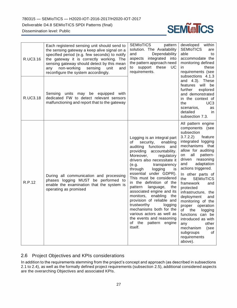
780315 — SEMIoTICS — H2020-IOT-2016-2017/H2020-IOT-2017
Deliverable D4.8 SEMIoTICS SPDI Patterns (final)
Dissemination level: Public
27
R.UC3.16
Each registered sensing unit should send to the sensing gateway a keep alive signal on a specified period (e.g. few seconds) to notify the gateway it is correctly working. The sensing gateway should detect by this mean any non-working sensing unit and reconfigure the system accordingly.
SEMIoTICS pattern solution. The Availability and Dependability aspects integrated into the pattern approach need to support these UC requirements.
developed within SEMIoTICS are able to accommodate the monitoring defined in these requirements (see subsections 4.1.3 and 4.3). These features will be further explored and demonstrated in the context of the UC3 scenarios, as detailed in subsection 7.3.
R.UC3.18 Sensing units may be equipped with dedicated FW to detect relevant sensors malfunctioning and report that to the gateway
R.P.12
During all communication and processing phases logging MUST be performed to enable the examination that the system is operating as promised
Logging is an integral part of security, enabling auditing functions and providing accountability. Moreover, regulatory drivers also necessitate it (e.g. transparency through logging is essential under GDPR). This must be considered in the definition of the pattern language, the associated engine and its monitors, enabling the provision of reliable and trustworthy logging mechanisms both for the various actors as well as the events and reasoning of the pattern engine itself.
All pattern engine components (see subsection 3.7.2.2) feature integrated logging mechanisms that allow for auditing on all pattern-driven reasoning and adaptation actions triggered.
In other parts of the SEMIoTICS framework and protected infrastructure, the deployment and monitoring of the proper operation of the logging functions can be introduced as with any other mechanism (see subgroups of requirements above).
Project Objectives and KPIs considerations
In addition to the requirements stemming from the project’s concept and approach (as described in subsections 2.1 to 2.4), as well as the formally defined project requirements (subsection 2.5), additional considered aspects are the overarching Objectives and associated KPIs.

780315 — SEMIoTICS — H2020-IOT-2016-2017/H2020-IOT-2017
Deliverable D4.8 SEMIoTICS SPDI Patterns (final)
Dissemination level: Public
28
While the work carried out within Task 4.1 directly targets Objective 1 of the project (“Objective 1: Development of patterns for orchestration of smart objects and IoT platform enablers in IoT applications with guaranteed security, privacy, dependability and interoperability (SPDI) properties” ), it is also relevant to various aspects of other overarching objectives of the project as well; e.g., the patterns specified herein are important enablers of the multi-layered embedded intelligence and semi-autonomic operation of SEMIoTICS, as sketched in Objective 4 of the project.
In this context, a detailed mapping of the work carried out in Task 4.1 to the overarching project objectives and the associated KPIs is presented in Table 3 and Table 4.
TABLE 3. PATTERN-SPECIFIC KPIS
Objective KPI Relation and Status
# Description ID Description
1 Development of patterns for orchestration of smart objects and IoT platform enablers in IoT applications with guaranteed security, privacy, dependability and interoperability (SPDI) properties.
KPI-1.1 Delivery of 36 verified SPDI patterns covering the 6 core property types for 3 data states and 2 cases
Pattern-driven SPDI management is at the core of the SEMIoTICS security-by-design approach. The final set of SPDI patterns is defined herein (see Section 4). As aggregated in subsection 4.6, 49 patterns are delivered in total, covering all key SPDI properties and different data states and cases of platform connectivity.
KPI-1.2 Machine-processable pattern language
The final version of the pattern language is defined and presented in detail herein (see Section 3 and Table 6), developed to accommodate all the needs of the SEMIoTICS pattern definition and reasoning.
TABLE 4. CONSIDERATIONS AND RELATION TO OTHER PROJECT OBJECTIVES AND ASSOCIATED KPIS
Objective KPI Relation and Status
# Description ID Description
2 Development of semantic interoperability mechanisms for smart objects, networks and IoT platforms.
KPI-2.1 Semantic descriptions for 6 types of smart objects
The pattern-driven approach of SEMIoTICS has been integrated with the usable IoT orchestrations framework leveraging Thing Descriptions (Task 3.3), as shown in sections 5 and 6 below. The role of the patterns in the associated use case featuring semantics aspects is detailed in subsection 7.1.
3 Development of dynamically and self-adaptable monitoring mechanisms supporting integrated and predictive monitoring of smart objects of all layers of the IoT
KPI-3.1 Delivery of a monitoring management layer for generating monitoring strategies for different checks and configurations of monitors available in the targeted IoT platforms
The initial semantics of a monitoring language, derived in the context of Task 4.2, are presented in D4.2 and the final ones in D4.9, while the associated SPDI monitoring properties are foreseen in the design of the SPDI model and associated pattern language (see subsections 3.3 and 3.4 and respectively).
KPI-3.2 Delivery of a monitoring language capable of

780315 — SEMIoTICS — H2020-IOT-2016-2017/H2020-IOT-2017
Deliverable D4.8 SEMIoTICS SPDI Patterns (final)
Dissemination level: Public
29
implementation stack in a scalable manner.
defining platform agnostic monitoring conditions (as part of SPDI patterns), correlations of different IoT platform events that are necessary for this, and predictive monitoring checks
4 Development of core mechanisms for multi-layered embedded intelligence, IoT application adaptation, learning and evolution, and end-to-end security, privacy, accountability and user control.
KPI-4.2 Delivery of adaptation mechanisms that support proactive and reactive, as well as horizontal and vertical adaptation actions, related to network, smart objects and IoT platforms with an adaptation time of 15ms
Pattern rules defined herein (see section 4), along with the associated pattern components able to reason on said pattern rules and facts (see subsection 3.7.2), will be key drivers behind the SEMIoTICS adaptations. This is in tandem with the proactive mechanisms (defined within D4.2 and D4.9), backend orchestration for management/adaptation (see D4.6).
KPI-4.6 Development of 3 new security mechanisms/controls enabling the secure management of smart devices and sensors over programmable industrial networks
The SPDI-focused pattern-driven monitoring and adaptation that is at the heart of the SEMIoTICS concept and is presented herein is one of the three core security-related innovations of the project and a key enabler of the multi-layered embedded intelligence of the platform.
6 Development of a reference prototype of the SEMIoTICS open architecture, demonstrated and evaluated in both IIoT (renewable energy) and IoT (healthcare), as well as in a horizontal use case bridging the two landscapes (smart sensing), and delivery of the respective open API.
KPI-6.1 Reduce Required Manual Interventions.
The semi-autonomic operation of the IoT deployment, through the multi-layered embedded intelligence capabilities that, among others, the pattern-driven approach presented herein provides, aims to reduce manual interventions and also effectively and efficiently mitigate the SPDI-related risks stemming from the faults introduced from erroneous or malicious human actions.

780315 — SEMIoTICS — H2020-IOT-2016-2017/H2020-IOT-2017
Deliverable D4.8 SEMIoTICS SPDI Patterns (final)
Dissemination level: Public
30
3 PATTERN LANGUAGE DEFINITION
Concept
Patterns are re-usable solutions to common problems and building blocks to architectures [21][22], the foundations of which were laid by the architect Christopher Alexander in his seminal work "The Timeless Way of Building" [23]. In other words, patterns describe a recurring problem that arises in specific context and presenting a well-proven, generic solution for it.
This section provides the final definition of the SEMIoTICS Pattern Language. Overall, this language:
- provides constructs for expressing/encoding dependencies between SPDI properties at the component and at the composition/orchestration level;
- is structural; It does not prescribe exactly how the functions should be executed nor, e.g., how the ports ensure communication;
- supports the static and dynamic verification of SPDI properties;
- is automatically processable by the SEMIoTICS framework so that IoT applications can be adapted at runtime.
Patterns expressed in the SEMIoTICS pattern language will enable the pattern based IoT application management process followed in SEMIoTICS, in which patterns are used to:
• design IoT applications that satisfy required SPDI properties
• verify that existing IoT applications satisfy required SPDI properties at design time, prior to the deployment of the application
• enable the adaptation of IoT applications or partial orchestrations of components within them at runtime in a manner that guarantees the satisfaction of required SPDI properties
To fulfil the above, SPDI patterns encode proven dependencies between security, privacy, dependability and interoperability (SPDI) properties of individual components of IoT applications and corresponding properties of orchestrations of such components. More specifically, a pattern encodes relationships of the form
P1 and P2 and … and Pn → Pn+1
where Pi (i=1,…,n) are properties of individual components and Pn+1 is a property of the orchestration of these components. The relation encoded by a pattern is an entailment relation.
The runtime adaptations that can be enabled by SPDI patterns may take three forms:
(1) to replace particular components of an orchestration
(2) to change the structure of an orchestration, and
(3) a combination of (1) and (2).
The above types of adaptations are exemplified in Figure 2, where we consider nodes (these could represent any atomic component; e.g., a physical device or a service) which are composed through links (e.g., a network connection) into more complex orchestrations (e.g., a complex workflow involving several services), forming a graph. As shown in the figure at the node level Node 1 is replaced by Node 1’. This adaptation may, for example, become necessary as a component of the role and type of Node 1 may be required (by a pattern) to have a security certificate to prove a property (e.g., encryption of data with a 256-bit algorithm) that is needed of the component for the overall system to fulfil another property (confidentiality). If at some point during runtime the (encryption) certificate of Node1 expires, the active pattern will trigger the replacement the component. Adaptations may also be at the link level. More specifically, a network link between Node 1 and Node 2 may be replaced with two links (two alternative networks) to offer increased redundancy (e.g. to achieve the required levels of dependability). Finally, adaptations may be triggered at graph level. In Figure 2, the graph containing Node 3, Node 4, Node 5 and their links is replaced completely with a new graph, containing Node 3’, Node 4’ and Node 5’ and their new links (e.g. to satisfy the need for a certain end-to-end security property).

780315 — SEMIoTICS — H2020-IOT-2016-2017/H2020-IOT-2017
Deliverable D4.8 SEMIoTICS SPDI Patterns (final)
Dissemination level: Public
31
SPDI patterns cover the different and heterogeneous orchestration models required for IoT and IIoT applications, covering aspects of both the high-level service orchestration view as well as the deployment view of said applications.
FIGURE 2. EXAMPLES OF PATTERN ADAPTATIONS AT THE NODE, LINK AND GRAPH LEVEL
Related Works
The popularity of Internet of Things (IoT) brought the realization that the application of semantic technologies (ontologies, semantic annotation, Linked Data and semantic Web services) to IoT offers many advantages with the most important of them being interoperability among IoT resources promoting the interoperability among data providers and consumers, data access and integration, resource discovery, semantic reasoning, and knowledge extraction. Semantic technologies are the principal solutions for the realization of the IoT [24]. However, the ultimate goal of achieving more capable and powerful applications remains and leads to service composition approaches oriented in the area of IoT.
There are some attempts for describing IoT service compositions such as those of [25], [26] and [27] which focus on the energy consumption of the involved IoT devices. The latter pays attention to QoS properties reducing the services search space and the composition time, but none of them takes under consideration possible Security properties of the individual IoT services or the whole composition.
Moreover, there is the work of [28] that introduce a contExt Aware web Service dEscription Language (wEASEL) is introduced. wEASEL is an abstract service model to represent services and user tasks in Ambient Assisted Living (AAL) environments. Attention is paid to data-flow and context-flow constraints for the service composition but the authors do not mention any security properties.

780315 — SEMIoTICS — H2020-IOT-2016-2017/H2020-IOT-2017
Deliverable D4.8 SEMIoTICS SPDI Patterns (final)
Dissemination level: Public
32
A work that includes security aspects is that of [29]. BPMN 2.0 is used for the description of the service choreographies that the built platform can synthesize and execute. Regarding the security aspect, the enforcement of security properties is exclusively done by the existing communication protocols since the security filter component is able to filter these protocols and keep only those that conform to the specified security requirements.
Finally, [30] present a mechanism that manages IoT choreographies at runtime dynamically. According to their approach IoT service compositions are described by templates called Recipes, which consist of Ingredients and their Interactions. In addition, there are more requirements described by offering selection rules (OSRs) that make the reconfiguration of the system possible during runtime. The authors’ service composition approach is semi-automated to avoid the complexity of the semantic models and the inefficiency of the reasoner due to the large number of available devices and services. We consider this approach closer to the way we envision a pattern language. Their way of IoT representation with the notions of Ingredients and Interactions, and the fact that the OSRs allow for requirement description inspired the creation of the language described in this chapter.
Table 5 in the next page summarizes related works on different approaches/frameworks of service composition. Given this survey of the SoTA, and considering the expertise available within the consortium, the choice is to combine the expertise on pattern-driven SPDI management with the Recipes approach by [30], tailoring the former to the intricacies of IoT environments covered in SEMIoTICS and extending the latter with SPDI property specification, monitoring and adaptation at design and at runtime (through said patterns).

780315 — SEMIoTICS — H2020-IOT-2016-2017/H2020-IOT-2017
Deliverable D4.8 SEMIoTICS SPDI Patterns (final)
Dissemination level: Public
TABLE 5: RELATED WORKS
Composition Category Title
Composition Type
Targeted Environment
Service representation Pros Cons Security
En
erg
y-co
nsum
ptio
n se
rvic
e co
mpo
sitio
n
Zhangbing Zhou, Deng Zhao, Lu Liu, Patrick C.K. Hung, “Energy-aware composition for wireless sensor networks as a service”, Future Generation Computer Systems, Volume 80, 2018, Pages 299-310, ISSN 0167-739X, https://doi.org/10.1016/j.future.2017.02.050.
Automated, static sensor nodes in wireless sensor networks (WSNs)
* WSN service is a tuple (nm,dsc, op, eng, spt, tpr), where (i) nm is the name, (ii) dsc is the text description, (iii) op is an operation (functionality), (iv) eng is the remaining energy, (v) spt is the spatial constraint, and (vi) tpr is the temporal constraint. * Service network snSC is a directed graph, and is represented as a tuple (SvC (=service classes), Lnk (=direct links), InvP (=invocation possibility))
+ approximately optimal WSN services compositions + no need for the users to represent their requirements in an explicit specification, just input, output and description + energy-aware service composition + high availability
- the linkage between services and physical sensor nodes is not explored - high complexity - low scalability - a certain, but limited number of service classes can be identified in a certain domain (service network)
Not covered / Not mentioned
Baker, Thar & Asim, Muhammad & Tawfik, Hissam & Aldawsari, Bandar & Buyya, Rajkummar. (2017). An Energy-aware Service Composition Algorithm for Multiple Cloud-based IoT Applications. Journal of Network and Computer Applications. 10.1016/j.jnca.2017.03.008.
Automated, static IoT A service is described by its provider in a 3-tuple format (si,so,sec), where sec is the energy required for the service computation at the hosting datacentre, si is the input and so is the output
+ power efficiency of the physical devices in composition approach + minimum number of IoT services in the composition +transitional relationships between the customer and the
- each cloud provider must have pre-defined/developed composition plans - high time and cost
Not covered / Not mentioned

780315 — SEMIoTICS — H2020-IOT-2016-2017/H2020-IOT-2017
Deliverable D4.8 SEMIoTICS SPDI Patterns (final)
Dissemination level: Public
34
datacenters are taken under consideration +superior performance against established composition algorithms
Da
ta-o
rie
nte
d se
rvic
e co
mp
ositi
on
A. Urbieta, A. González-Beltrán, S. Ben Mokhtar, M. Anwar Hossain, L. Capra, “Adaptive and context-aware service composition for IoT-based smart cities”, Future Generation Computer Systems, Volume 76, 2017, Pages 262-274
Automated, static IoT contExt Aware web Service dEscription Language (wEASEL)
+ deals simultaneously with signature and specification matching and supports several concept matching techniques
- no QoS attributes in the evaluation
Not covered / Not mentioned
Montori, Federico & Bedogni, Luca & Bononi, Luciano. (2017). A Collaborative Internet of Things Architecture for Smart Cities and Environmental Monitoring. IEEE Internet of Things Journal. PP. 1-1. 10.1109/JIOT.2017.2720855.
Automated, static IoT N/A + exploitation of the devices owned by the end users +crowdsensing +homogeneity to data
- end users must want to participate (may want a reward) - some sources may be unreliable - no prediction for sensitive information - single point of failure (server-client system)
Not covered / Not mentioned
IP-b
ase
d se
rvic
e
com
posi
tion
Kleinfeld, Robert & Steglich, Stephan & Radziwonowicz, Lukasz & Doukas, Charalampos. (2014). glue.things – a Mashup Platform for wiring the Internet of Things with the Internet of Services. 10.13140/2.1.3039.9049.
Designer, static Web-enabled IoT devices, web services
Json-based data models (triggers and actions)
+ token management of devices + user management + integration of IoT and web services, + Interfaces for registration, configuration and monitoring
- availability of nodes - low scalability
Web service authorisation with OAuth

780315 — SEMIoTICS — H2020-IOT-2016-2017/H2020-IOT-2017
Deliverable D4.8 SEMIoTICS SPDI Patterns (final)
Dissemination level: Public
35
Chen, Lei & Englund, Cristofer. (2017). Choreographing Services for Smart Cities: Smart Traffic Demonstration. 1-5. 10.1109/VTCSpring.2017.8108625.
Designer IoT N/A + runtime insurance for services communication, + BPMN usage
- platform under construction, - availability of stakeholders
Filters the interaction protocols of the service with respect to different security requirements
Doukas, Charalampos & Antonelli, Fabio. (2015). Developing and deploying end-to-end interoperable & discoverable IoT applications. 673-678. 10.1109/ICC.2015.7248399.
Designer (uses Node-RED), static
IoT iServe (a service warehouse which unifies service publication, analysis, and discovery through the use of lightweight semantics as well as advanced discovery and analytic capabilities.)
+ bridge between REST and MQTT/ WebSockets/STOMP, + reuse of services, + monitoring
- availability of services
Access control, Data privacy, Integrity
Georgios Pierris , Dimosthenis Kothris , Evaggelos Spyrou , Costas Spyropoulos, SYNAISTHISI: an enabling platform for the current internet of things ecosystem, Proceedings of the 19th Panhellenic Conference on Informatics, October 01-03, 2015, Athens, Greece [doi>10.1145/2801948.2802019]
Designer, static IoT (sensors, processors, actuators)
IoT ontology + SNN ontology + qu-rec20 ontology
+ Reuse of registers services, + secure storage
- no GUI yet, - availability of services, - no runtime monitoring
Authentication, Authorisation, Data-anonymization in storage
Mayer, Simon & Verborgh, Ruben & Kovatsch, Matthias & Mattern, Friedemann. (2016). Smart Configuration of Smart Environments. IEEE Transactions on Automation Science and Engineering. 13. 1-9. 10.1109/TASE.2016.2533321.
Automated (goal-driven configuration), dynamic
IoT, Web of things
RESTdesc expressed in Notation3
+ adaptation to dynamic environments, + fault tolerance, + scalability, + correct service composition, + security requirements
- no universal remedy for false compositions, - inefficient reasoning for large number of devices
Confidentiality of data exchanged within a mashup
J. Seeger, R. A. Deshmukh and A. Broring, "Running Distributed and Dynamic IoT Choreographies," in Global IoT Summit (GIoTS), Bilbao, 2018.
Designer, dynamic IoT Recipe, Offerings, OSRs, RRCs
+ Dynamic update of IoT components, + choreography approach, + scalability, + failure detection
- No SDN support yet - Limited availability of offerings
Not covered / Not mentioned

780315 — SEMIoTICS — H2020-IOT-2016-2017/H2020-IOT-2017
Deliverable D4.8 SEMIoTICS SPDI Patterns (final)
Dissemination level: Public
36
Huber, Steffen & Seiger, Ronny & Kühnert, André & Schlegel, Thomas. (2016). Using Semantic Queries to Enable Dynamic Service Invocation for Processes in the Internet of Things. 10.1109/ICSC.2016.75.
Designer (table-based editors for Ecore models), dynamic
IoT arbitrary ontologies can be integrated (DogOnt ontology)
+ concept can be generalized and applied to different models and systems from the BPM and IoT communities + allows for context-sensitive resource allocation
- In large-scale systems containing more than 106 IoT services, service discovery and invocation will most likely take minute - SPARQL queries introduces an additional overhead
Not covered / Not mentioned
Oth
er
(No
Se
rvic
e C
omp
ositi
on
Nambi, S. & Sarkar, Chayan & Prasad, Venkatesha & Biswas, Abdur Rahim. (2014). A unified semantic knowledge base for IoT. 2014 IEEE World Forum on Internet of Things, WF-IoT 2014. 575-580. 10.1109/WF-IoT.2014.6803232.
N/A IoT Resource Ontology, Location ontology (extension of GeoNames ontology), Context and Domain Ontologies (Aspect-Scale-Context), Policy ontology (Belief-Desire-Intention-Policy model), Service ontology (extension of OWL-S)
+ The proposed knowledge base integrates several existing ontologies that were mainly related to sensor resources, web services and extends them for IoT
- This is just the knowledge base and they do not mention anything about composition of services
Not covered / Not mentioned
W. Wang, S. De, R. Toenjes, E. Reetz, and K. Moessner, ‘‘A comprehensive ontology for knowledge representation in the Internet of Things,’’ in Proc. IEEE 11th Int. Conf. Trust, Secur. Privacy Comput. Commun. (TrustCom), Jun. 2012, pp. 1793–1798
N/A IoT IoT service is a subclass of the Service class defined in the OWL-S, therefore, an IoT Service can have one Service Profile and one Process that describe its functional and non-functional properties, as well as links to domain knowledge
+ functional and non-functional properties for the services, + a model-based approach to guide automatic test generation and control
- Νο QoS and QoL aware methods for service composition and adaptation
Not covered / Not mentioned

780315 — SEMIoTICS — H2020-IOT-2016-2017/H2020-IOT-2017
Deliverable D4.8 SEMIoTICS SPDI Patterns (final)
Dissemination level: Public
37
(e.g., service category and physical location ontologies),
Vögler, Michael & Li, Fei & Claeßens, Markus & Schleicher, Johannes & Sehic, Sanjin & Nastic, Stefan & Dustdar, Schahram. (2015). COLT Collaborative Delivery of Lightweight IoT Applications. 10.1007/978-3-319-19656-5_38.
N/A ΙοΤ An IoT Application is represented as a self-contained archive with corresponding metadata, containing the following information: (i) a Name that uniquely identifies the application, (ii) a natural language Description, (iii) Provider name and id, (iv) a list of Suitable Devices the application can be deployed and executed on, and (v) a Version number
+ browse the market for applications + buy and deploy applications +monitoring component
- Νο pricing and revenue sharing models that allow more stakeholders that are involved in the development process, to collaborate
Not covered / Not mentioned

780315 — SEMIoTICS — H2020-IOT-2016-2017/H2020-IOT-2017
Deliverable D4.8 SEMIoTICS SPDI Patterns (final)
Dissemination level: Public
IoT Application Architecture and Orchestration Modelling
The overall objective of SEMIoTICS is to develop a framework that will be capable of managing the IoT applications based on patterns. Therefore, it is necessary to develop a language for specifying the components that constitute such applications along with their interfaces and interactions. Thus, the security and other quality properties may be required of such components and their orchestrations. A model with such characteristics will effectively serve as a general “architecture and workflow model” of the IoT application. Once defined, this model will be used in conjunction with patterns to enable the reasoning required for determining the applicability of particular SPDI patterns in specific IoT applications and subsequently reason based on them to enable the different types of adaptation that were introduced in subsection 3.1.
The development of the language for specifying an IoT application architecture and workflow model (referred to as “IoT application model” in the rest of this deliverable) has also taken into account the requirements identified in Section 2 and the current SoTA presented in subsection 3.2.
For the creation of the IoT application model we used Eclipse that through the EMF modelling framework enables the use of the default tree-based editor. The tree-based editor allows to define properties for classes, attributes and references.
The basic constructs for defining an IoT application model in SEMIoTICS is shown in Figure 3.The figure shows the basic modelling constructs of the language and their relations in the form of a UML diagram3.
3 http://www.uml.org/

780315 — SEMIoTICS — H2020-IOT-2016-2017/H2020-IOT-2017
Deliverable D4.8 SEMIoTICS SPDI Patterns (final)
Dissemination level: Public
39
FIGURE 3. SEMIOTICS IOT ORCHESTRATION SYSTEM MODEL
The language for defining IoT application models advocates an orchestration-based approach. In this approach, the interactions between the different types of components of such applications (e.g., software components, software services, sensors, actuators) interact with each other as specified as orchestration(s) within the IoT application. Such orchestrations are modelled by the class Orchestration in Figure 3. An orchestration of activities may be of different types depending on the order in which the different activities involved in it must be executed. According to this criterion, an orchestration may be defined as a Sequential, Parallel, Merge, Choice or Iterate orchestration. The meaning of these types of orchestrations is as follows:
(i) Sequence is a segment of a process instance in which several activities are executed in sequence under a single thread of execution.
(ii) Parallel is a segment of a process instance where two or more activity instances are executing in parallel within the workflow, giving rise to multiple threads of control.
(iii) Merge is a point in the workflow where two or more parallel executing/alternative activities converge into a single common thread of control.
(iv) Choice is a point within the workflow where a single thread of control makes a decision upon which branch to take when encountered with multiple alternative workflow branches, based on a choice condition.

780315 — SEMIoTICS — H2020-IOT-2016-2017/H2020-IOT-2017
Deliverable D4.8 SEMIoTICS SPDI Patterns (final)
Dissemination level: Public
40
(v) Iterates is a workflow activity cycle involving the repetitive execution of one (or more) workflow activity(s) until a condition is met.
Moreover, an orchestration involves orchestration activities (see class OrchestrationActivity in Figure 3). At any instance of time, these activities may have a known implementation or a not known implementation. In the former case, the activity will be a linked activity (see class LinkedActivity in Figure 3). In the latter, the activity will be an unassigned activity (see class UnassignedActivity in Figure 3). Unassigned activities in an IoT application orchestration may exist during the design of the IoT application, when the exact implementation of a specific orchestration activity might not have been decided yet or at runtime when the particular component that used to provide the implementation of the activity can no longer be used (because, for example, it might be unavailable or because it no longer fulfils the properties required of it) and must be replaced.
The implementation of an activity in an IoT application orchestration may be provided by:
(i) A software component, i.e., a software module with an available and modifiable implementation that encapsulates a set of functions and data and makes them available through a programmatic interface.
(ii) A software service, i.e., a software module that encapsulates a set of functions and data and makes them available through a programmatic interface, accessible remotely over a network, whose implementation is neither available to the owner nor modifiable.
(iii) A network component, such as software defined network controllers, software switches/vSwitches, and potentially legacy networking components.
(iv) An IoT sensor, i.e., a device that collects data from the environment or object under measurement and turns it into useful data.
(v) An IoT actuator, i.e., a device that takes electrical input and transforms the input into tangible action.
(vi) An IoT gateway, i.e., is a physical device or software program that serves as the connection point between the field devices and the SEMIoTICS backend, via the software-defined network layer.
(vii) A (sub) orchestration of IoT application activity implementers of types (i) to (vi).
Software component may also represent external IoT platform services. By adding this class to our model, the description of two different types of platform connectivity, within SEMIoTICS project and across IoT platforms, becomes feasible. In that way we can create patterns that can be used for the verification of SPDI properties in IoT application orchestrations described just within the SEMIoTICS ecosystem and/or across SEMIoTICS and other IoT platform services, such as FIWARE.
The above types of IoT application activity implementers are grouped under the general concept of placeholder (see the class Placeholder in Figure 3). The language introduces also subclasses of the general class Placeholder to represent the above elements. These are the classes Orchestration and OrchestrationActivity. As already described Orchestration class above, the OrchestrationActivity class is extended by LinkedActivity and UnassignedActivity classes. Both of these classes have an attribute Name to identify them unambiguously. LinkedActivity, referring to activities whose implementation is known, defines the specification of the SDPI properties of the involved activity. On the other hand, UnassignedActivity, referring to a not known implementation, requires a ThingDescription, which provides the details on how the activity is implemented, the characteristics of the underlying devices and relevant parameters (e.g., IP address, exposed endpoints, available resources), the corresponding SDPI properties, etc. For the exact information that may be included within these Thing Descriptions, please refer to Deliverable D3.3 – “Bootstrapping and interfacing SEMIoTICS field level devices (first draft)”.
A placeholder is accessible through a set of interfaces. An interface is a named set of operations through which the functions and the data of the placeholder can be accessed from any element outside it. Interfaces are represented by the class Interface in Figure 3. The interfaces through which a placeholder can be accessed are linked to the placeholder as the interfaces that it provides (see provides association end between the class Placeholder and Interface in Figure 3). In addition, placeholders may require additional interfaces provided by other placeholders for them to function properly. A placeholder P1 that provides access to a set of data may, for example, authenticate data access requests by relying to another placeholder P2 with responsibility for authentication and authorisation checks over users. In this case, P2 would be modelled as a placeholder that

780315 — SEMIoTICS — H2020-IOT-2016-2017/H2020-IOT-2017
Deliverable D4.8 SEMIoTICS SPDI Patterns (final)
Dissemination level: Public
41
provides two interfaces, i.e., an authentication and an authorisation interface, and P1 as a placeholder that requires these two interfaces. Requires relations between placeholders and interfaces are modelled through requires association end between the class Placeholder and Interface in Figure 3.
The individual operations that constitute the interface of a placeholder are represented by the class Operation in Figure 3. As shown in the figure an operation has a set of parameters: i) name, ii) input and iii) output. Name is used as an identifier for the Operation and the input and output are a set of Parameters. If we assume that an activity PaymentService is to be invoked, the name of the operation could be “payment” and the input/output could be a set of parameters such as the items to be purchased, the number of the credit card and the address for the items to be delivered.
Placeholders (of all different types) may also be characterised by their SPDI and QoS properties. A property of a placeholder is specified according to the class Property in Figure 3. According to it, a Property has a name, a type, a verification, a category and a dataState. The attribute type refers to the state of the property, which can be required or confirmed. A required property is a property that a placeholder must hold in order to be included (considered for) the orchestration. For example, if the required property of an orchestration defining a secure logging process is Confidentiality, then all placeholder activities involved in the orchestration and the links between them may be required to have the Confidentiality property. On the other hand, a confirmed property is a property that is verified at runtime, through a specific means as defined in the Verification.
Verification is a class that describes the way a Property of a Placeholder is verified. The verification process can be done through monitoring, testing, a certificate or via a pattern. This means that the existence of a monitoring service or a testing tool allows the verification of the SPDI property of a placeholder activity. Such a monitoring service could, for example, justify that a service or a device is available at specific time windows if the desirable property is a specific target for availability. Another way of verifying SPDI properties could be a repository with certificates that are able to justify that a certain placeholder satisfies a certain property. In case of a pattern the Mean of verification is the pattern itself; in all the other cases we need an interface to a corresponding monitoring tool, testing service or certificate repository through which the verification can take place.
Moving on with category attribute, the Category enumerator in Figure 3 shows the different categories. A Property can belong to confidentiality, integrity, availability, privacy, dependability, interoperability or QoS. In this way a classification of the properties is achieved.
The final attribute, dataState, is referred to state of the data of a Placeholder (see enumerator DataState in Figure 3). In SEMIoTICS, all three data states are considered, i.e. data in transit, at rest or in processing. If the Placeholder is an Orchestration, then the state of the data will be “in_transit”. If we have to do with an OrchestrationActivity and the OrchestrationActivity is bound to a storage service for example, then dataSate could also be “at_rest”. If the OrchestrationActivity is bound to a service or device that transforms data, then dataSate could be “in_processing”. This attribute was added in the model to allow description of different pattern regarding the three aforementioned data states. This can be done by creating Orchestrations that are subjects to Properties with variant datastates.
Finally, the set of all the SPDI properties that are inferred for the different placeholders of an orchestrator by a pattern are aggregated into PropertyPlan object.
Language Constructs
Based on the IoT application model presented above we created a corresponding language the constructs of which are described using an EBNF grammar. This language can be used to define activities, as well as basic control flow operations (namely sequential, parallel, choice and merge) enabling their composition into complex orchestrations, and to define the associated individual and composition properties. Upon instantiation of the orchestration, the abstract definition of the orchestration structure is replaced with the actual components implementing said orchestration. This grammar, which is a textual representation of the IoT application model presented above, is shown in Table 6.
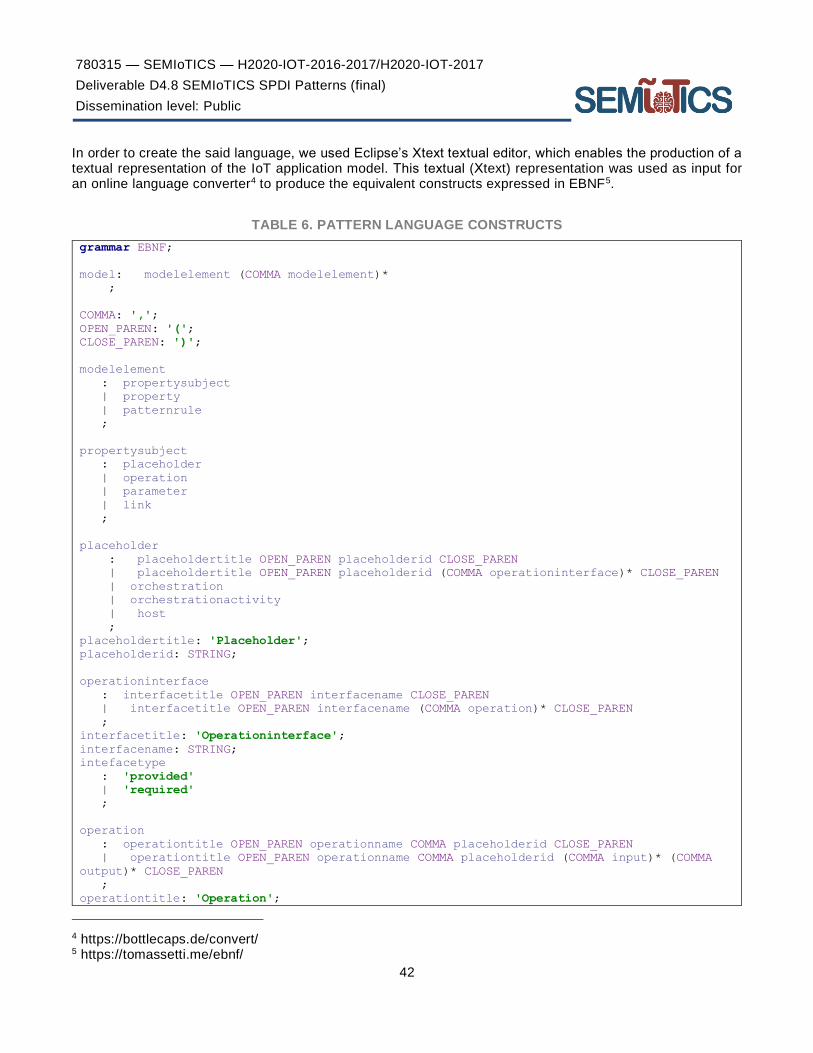
780315 — SEMIoTICS — H2020-IOT-2016-2017/H2020-IOT-2017
Deliverable D4.8 SEMIoTICS SPDI Patterns (final)
Dissemination level: Public
42
In order to create the said language, we used Eclipse’s Xtext textual editor, which enables the production of a textual representation of the IoT application model. This textual (Χtext) representation was used as input for an online language converter4 to produce the equivalent constructs expressed in EBNF5.
TABLE 6. PATTERN LANGUAGE CONSTRUCTS
grammar EBNF;
model: modelelement (COMMA modelelement)*
;
COMMA: ',';
OPEN_PAREN: '(';
CLOSE_PAREN: ')';
modelelement
: propertysubject
| property
| patternrule
;
propertysubject
: placeholder
| operation
| parameter
| link
;
placeholder
: placeholdertitle OPEN_PAREN placeholderid CLOSE_PAREN
| placeholdertitle OPEN_PAREN placeholderid (COMMA operationinterface)* CLOSE_PAREN
| orchestration
| orchestrationactivity
| host
;
placeholdertitle: 'Placeholder';
placeholderid: STRING;
operationinterface
: interfacetitle OPEN_PAREN interfacename CLOSE_PAREN
| interfacetitle OPEN_PAREN interfacename (COMMA operation)* CLOSE_PAREN
;
interfacetitle: 'Operationinterface';
interfacename: STRING;
intefacetype
: 'provided'
| 'required'
;
operation
: operationtitle OPEN_PAREN operationname COMMA placeholderid CLOSE_PAREN
| operationtitle OPEN_PAREN operationname COMMA placeholderid (COMMA input)* (COMMA
output)* CLOSE_PAREN
;
operationtitle: 'Operation';
4 https://bottlecaps.de/convert/ 5 https://tomassetti.me/ebnf/

780315 — SEMIoTICS — H2020-IOT-2016-2017/H2020-IOT-2017
Deliverable D4.8 SEMIoTICS SPDI Patterns (final)
Dissemination level: Public
43
operationname: STRING;
input
: parameter
| parametername
;
output
: parameter
| parametername
;
parameter
: parametertitle OPEN_PAREN parametername COMMA parametertype COMMA propertyname (COMMA
propertyname)* CLOSE_PAREN
;
parametertitle: 'Parameter';
parametername: STRING;
parametertype
: 'soap'
| 'rest'
;
link
: linktitle OPEN_PAREN linkid COMMA placeholdera COMMA placeholderb CLOSE_PAREN
;
linktitle: 'Link';
linkid: STRING;
placeholdera
: placeholder
| placeholderid
;
placeholderb
: placeholder
| placeholderid
;
placeholderc
: placeholder
| placeholderid
;
property
: propertytittle OPEN_PAREN propertyname COMMA propertytype COMMA category COMMA value
COMMA datastate COMMA verification COMMA subject COMMA satisfied CLOSE_PAREN
;
propertytittle: 'Property';
propertyname: STRING;
propertytype
: 'required'
| 'confirmed'
| 'propertytype'
;
category
: 'confidentiality'
| 'integrity'
| 'availability'
| 'privacy'
| 'dependability'
| 'interoperability'
| 'qos_delay'
| 'qos_bandwidth'

780315 — SEMIoTICS — H2020-IOT-2016-2017/H2020-IOT-2017
Deliverable D4.8 SEMIoTICS SPDI Patterns (final)
Dissemination level: Public
44
| 'qosbandwidth'
| 'qos_protect'
| 'propertycategory'
| 'path'
;
value: STRING;
datastate
: 'at_rest'
| 'in_transit'
| 'in_processing'
| 'end_to_end'
| 'datastate'
;
subject
: placeholderid
| linkid
| operationname
| parametername
| sequenceid
;
source: STRING;
destination: STRING;
flavour
: 'atomic'
| 'composite'
;
satisfied: BOOLEAN;
verification
: verificationtitle OPEN_PAREN verificationtype COMMA means CLOSE_PAREN
;
verificationtitle: 'Verification';
verificationtype
: 'patternbased'
| 'monitoring'
| 'testing'
| 'certificate'
| 'verificationtype'
;
means
: 'pattern'
| 'interface'
| patternruleid
| 'means'
;
propertyplan
: propertyplantitle OPEN_PAREN propertyname (COMMA propertyname)* CLOSE_PAREN
;
propertyplantitle: 'Propertyplan';
orchestration
: sequence
| parallel
| choice
| merge
| iterate
| split
;

780315 — SEMIoTICS — H2020-IOT-2016-2017/H2020-IOT-2017
Deliverable D4.8 SEMIoTICS SPDI Patterns (final)
Dissemination level: Public
45
sequence
: sequencetitle OPEN_PAREN sequenceid COMMA placeholdera COMMA placeholderb COMMA
orchlink CLOSE_PAREN
;
sequencetitle: 'Sequence';
sequenceid: STRING;
orchlink: STRING;
merge
: mergetitle OPEN_PAREN mergeid COMMA placeholdera COMMA placeholderb COMMA
placeholderc COMMA orchlink COMMA orchlink2 CLOSE_PAREN
;
mergetitle: 'Merge';
mergeid: STRING;
orchlink2: STRING;
choice
: choicetitle OPEN_PAREN choiceid COMMA placeholdera COMMA placeholderb COMMA
placeholderc COMMA orchlink COMMA orchlink2 CLOSE_PAREN
;
choicetitle: 'Choice';
choiceid: STRING;
split
: splittitle OPEN_PAREN splitid COMMA placeholdera COMMA placeholderb COMMA
placeholderc COMMA orchlink COMMA orchlink2 CLOSE_PAREN
;
splittitle: 'Split';
splitid: STRING;
parallel
: paralleltitle OPEN_PAREN parallelid COMMA placeholdera COMMA placeholderb CLOSE_PAREN
;
paralleltitle: 'Parallel';
parallelid: STRING;
iterate
: iteratetitle OPEN_PAREN iterateid COMMA placeholdera COMMA placeholderb OPEN_PAREN
;
iteratetitle: 'Iterate';
iterateid: STRING;
host
: hosttitle OPEN_PAREN hostid COMMA mac COMMA activityaddress CLOSE_PAREN
;
hosttitle: 'Host';
hostid: STRING;
mac: STRING;
orchestrationactivity
: linkedactivity
| unassignedactivity
| softwareservice
| softwarecomponent
| networkcomponent
| iotsensor
| iotactuator
| iotgateway
| orchestrationactivityid
;

780315 — SEMIoTICS — H2020-IOT-2016-2017/H2020-IOT-2017
Deliverable D4.8 SEMIoTICS SPDI Patterns (final)
Dissemination level: Public
46
orchestrationactivityid: STRING;
activityaddress: STRING;
activityport: STRING;
linkedactivity
: linkedactivitytitle OPEN_PAREN linkedactivityid CLOSE_PAREN
| linkedactivitytitle OPEN_PAREN linkedactivityid COMMA activityaddress CLOSE_PAREN
| linkedactivitytitle OPEN_PAREN linkedactivityid COMMA activityaddress COMMA
activityport CLOSE_PAREN
;
linkedactivitytitle: 'Linkedactivity';
linkedactivityid: STRING;
unassignedactivity
: unassignedactivitytitle OPEN_PAREN unassignedactivityid CLOSE_PAREN
| unassignedactivitytitle OPEN_PAREN unassignedactivityid COMMA activityaddress
CLOSE_PAREN
| unassignedactivitytitle OPEN_PAREN unassignedactivityid COMMA activityaddress COMMA
activityport CLOSE_PAREN
;
unassignedactivitytitle: 'Unassignedactivity';
unassignedactivityid: STRING;
softwareservice
: softwareservicetitle OPEN_PAREN softwareserviceid CLOSE_PAREN
;
softwareservicetitle: 'Softwareservice';
softwareserviceid: STRING;
softwarecomponent
: softwarecomponenttitle OPEN_PAREN softwarecomponentid COMMA activityport COMMA hostid
CLOSE_PAREN
;
softwarecomponenttitle: 'Softwarecomponent';
softwarecomponentid: STRING;
networkcomponent
: networkcomponenttitle OPEN_PAREN networkcomponentid CLOSE_PAREN
| networkcomponenttitle OPEN_PAREN networkcomponentid COMMA activityaddress
CLOSE_PAREN
| networkcomponenttitle OPEN_PAREN networkcomponentid COMMA activityaddress COMMA
activityport CLOSE_PAREN
;
networkcomponenttitle: 'Networkcomponent';
networkcomponentid: STRING;
iotsensor
: iotsensortitle OPEN_PAREN iotsensorid CLOSE_PAREN
| iotsensortitle OPEN_PAREN iotsensorid COMMA activityaddress CLOSE_PAREN
| iotsensortitle OPEN_PAREN iotsensorid COMMA activityaddress COMMA activityport
CLOSE_PAREN
;
iotsensortitle: 'Iotsensor';
iotsensorid: STRING;
iotactuator
: iotactuatortitle OPEN_PAREN iotactuatorid CLOSE_PAREN
| iotactuatortitle OPEN_PAREN iotactuatorid COMMA activityaddress CLOSE_PAREN
| iotactuatortitle OPEN_PAREN iotactuatorid COMMA activityaddress COMMA activityport

780315 — SEMIoTICS — H2020-IOT-2016-2017/H2020-IOT-2017
Deliverable D4.8 SEMIoTICS SPDI Patterns (final)
Dissemination level: Public
47
CLOSE_PAREN
;
iotactuatortitle: 'Iotactuator';
iotactuatorid: STRING;
iotgateway
: iotgatewaytitle OPEN_PAREN iotgatewayid CLOSE_PAREN
| iotgatewaytitle OPEN_PAREN iotgatewayid COMMA activityaddress CLOSE_PAREN
| iotgatewaytitle OPEN_PAREN iotgatewayid COMMA activityaddress COMMA activityport
CLOSE_PAREN
;
iotgatewaytitle: 'Iotgateway';
iotgatewayid: STRING;
patternrule
: patternruletitle OPEN_PAREN patternruleid COMMA propertyname (COMMA propertyname)*
INFER propertyname CLOSE_PAREN
;
patternruletitle: 'Patternrule';
patternruleid: STRING;
INFER: '->';
STRING : '"' (ESC | ~["\\])* '"' ;
fragment ESC : '\\' (["\\/bfnrt] | UNICODE) ;
fragment UNICODE : 'u' HEX ;
fragment HEX : [0-9a-fA-F] ;
NUMBER
: '-'? INT '.' [0-9]+ EXP? // 1.35, 1.35E-9, 0.3, -4.5
| '-'? INT EXP // 1e10 -3e4
| '-'? INT // -3, 45
;
fragment INT : '0' | [1-9] [0-9]* ; // no leading zeros
fragment EXP : [Ee] [+\-]? INT ; // \- since - means "range" inside [...]
WS : [ \t\n\r]+ -> skip ;
BOOLEAN
: 'true'
| 'false'
;
Specification of SPDI patterns
SPDI patterns encode proven dependencies between SPDI properties of individual placeholders implementing activities in IoT applications orchestrations (i.e. activity-level SPDI properties) and SPDI properties of these orchestrations (i.e. workflow-level SPDI properties). The specification of an SPDI pattern consists of four parts:
i. The Activity Properties (AP) part, which defines the activity-level SPDI properties which are required of the activity placeholders present in the workflow of the pattern to allow for the guarantee of the OP properties detailed in the corresponding part of the pattern.
ii. The Orchestration (ORCH) part, which defines the abstract form of the orchestration that the pattern applies to. As such, the ORCH is specified as an orchestration of abstract activity placeholders. When the pattern is matched against a specific orchestration, the placeholders in its ORCH may be bound to operations of specific nodes or sub-orchestrations of it.

780315 — SEMIoTICS — H2020-IOT-2016-2017/H2020-IOT-2017
Deliverable D4.8 SEMIoTICS SPDI Patterns (final)
Dissemination level: Public
48
iii. The Conditions part, which defines the functional requirements, the states or the constraints that a system should define or what a system must do and how it reacts on specific inputs or situations.
iv. The Orchestration Properties (OP) part, which defines the orchestration-level SPDI properties that the pattern can guarantee for the orchestration specified in its ORCH part.
Based on the above, a semantic interpretation of an SPDI pattern having the above structure is that if the AP properties that have been specified for the activity placeholders in the orchestration of the pattern and the conditions of the pattern hold (verified as True), then the OP property specified in the pattern also holds for the whole ORCH. Formally, this can be expressed as:
𝐴𝑃 ⋀ 𝑂𝑅𝐶𝐻 ⋀ 𝐶𝑂𝑁𝐷𝐼𝑇𝐼𝑂𝑁𝑆 ⊨ 𝑂𝑃,
where ⊨ denotes the entailment relation that has been established by the proof of the pattern.
APs are materialized using the Property class in Figure 3. Property name identifies uniquely the SPDI property and the PropertySubject depicts the Placeholder that implements the activity for which the property is required or verifiable (PropertyType). In the latter case, PropertyVerification depicts how the verification takes place. PropertyCategory classifies the SPDI property, while DataState show that state of the data used by the Placeholder.
ORCH is an Orchestration object including Placeholders of type UnassignedActivity, making our model parametric since it does not have to refer to exact placeholders. This Orchestration can be of different types (Sequential, Parallel, Merge, Choice or Iterate) depending on the order that the involved activities are executed.
CONDITIONS are materialized using the Operation and Parameters classes. Inputs and outputs of the activity placeholders of the SPDI pattern are defined in the objects of those two classes.
Finally, OP is an orchestration-wide Property object. That means that values of some of its attributes are pre-defined, such as the PropertySubject, which is the ORCH described above, and the DataState that is set to “end-to-end”.
Example of Orchestration Definition
To showcase the use of the above, let us consider an example of a simple orchestration involving three activities in a sequential composition, as depicted in Figure 4.
FIGURE 4. A SIMPLE SEQUENTIAL ORCHESTRATION INVOLVING THREE ACTIVITIES
The sequential orchestration pattern, which will be applied twice to define the above, is defined as follows:
0. _ORCH “Seq2”
1. Placeholder (_a, (ActivityName, Description))
2. Placeholder (_b, (ActivityName, Description))
3. Sequence (_a, _b)

780315 — SEMIoTICS — H2020-IOT-2016-2017/H2020-IOT-2017
Deliverable D4.8 SEMIoTICS SPDI Patterns (final)
Dissemination level: Public
49
4. Link (_l1, _a, _b)
5. Property (_p1, _a, PropertyType, (VerificationType, VerificationMeans), PropertyCategory, DataState)
6. Property (_p2, _l1, PropertyType, (VerificationType, VerificationMeans), PropertyCategory, “in_transit”)
7. Property (_p3, _b, PropertyType, (VerificationType, VerificationMeans), PropertyCategory, DataState)
8. Property (_OP, “ConfSeq2”, required, (pattern-based, _PR), PropertyCategory, “end_to_end”)
9. PatternRule (_PR: _p1, _p2, _p3 → _OP)
In the above, the underscore before the name (e.g. as in “_a”) is used to express that these are placeholders, which, as mentioned, will be replaced with actual activities when the pattern is matched to actual workflows. Line 3 denotes that the orchestration type between the activities is sequential (other orchestration patterns are also supported, as mentioned above; e.g. Parallel(_a,_b)). Moreover, the involved activities are further specified within the pattern in lines 1 & 2, to define specific parameters about each, if needed. Furthermore, the link between the activities has be specified, as managing and monitoring the properties of the networking infrastructure is an important aspect of the SEMIoTICS framework and also necessary to guarantee the end-to-end satisfaction of individual properties. Therefore, line 4 defines the links between the involved activities and their type. Lines 5 to 7 define Activity Properties (AP), such as _p1 for placeholder _a and _p2 for _l1, i.e. the link between placeholders _a and _b. Finally, line 8 includes an Orchestration Property (OP) that can be guaranteed as long as the Activity Properties _p1 to _p3 hold, as defined in pattern rule _PR (defined in line 9).
The sequential orchestration pattern of Figure 4, which involves three activities, can be defined via the “Seq2” orchestration pattern as follows:
_ORCH “Seq3” : Sequence (_a, _b, _c) == _ORCH “Seq2” : Sequence (Sequence (_a, _b), _c)
Therefore, activities _a and _b are composed into a single (complex) activity by applying the sequential orchestration pattern “Seq2”, and the resulting activity forms the first part of the next application of “Seq2”, with _c as the second term in it.
When instantiating the above template, the placeholders are substituted by specific activities (or orchestrations of activities, which can be considered as sub-orchestrations), and also the properties become specific. Continuing with the same example above, a specific instance of the orchestration template can be seen in Figure 5 below, whereby placeholders _a, _b and _c are instantiated with activities “A1”, “A2” and “A3”, respectively.
FIGURE 5. INSTANCE OF THE SEQ3 ORCHESTRATION DEPICTED IN FIGURE 4
Thus, the description of the instance of the orchestration of Figure 4, as shown in Figure 5, can be defined by replacing placeholder _a with activity “A1” (e.g. , _b with activity “A2” and _c with activity “A3”. Then the individual descriptions become specific, such as:
- Placeholder (A1, (PaymentActivity, PaymentDescription))
- Placeholder (A2, (PlaceOrderActivity, PlaceOrderDescription))

780315 — SEMIoTICS — H2020-IOT-2016-2017/H2020-IOT-2017
Deliverable D4.8 SEMIoTICS SPDI Patterns (final)
Dissemination level: Public
50
- Placeholder (A3, (WriteReportActivity, WriteReportDescription))
- Link (L1, A1, A2)
- Link (L2, Α2, Α3)
The same goes for the individual and orchestration-wide properties; examples include:
- Property (P1, A1, required, (monitoring, interface), confidentiality, in_processing)
- Property (P2, L1, required, (monitoring, interface), confidentiality, in_transit)
- Property (P3, A2, required, (pattern-based, PSP), confidentiality, in_processing)
- Property (P4, L2, required, (monitoring, interface), confidentiality, in_transit)
- Property (P5, A3, required, (certificate, interface), confidentiality, at_rest)
- Property (OP, “Seq2”, required, (pattern-based, PR1), confidentiality, “end_to_end”)
In the above instantiation example, we assume that the end-to-end confidentiality is pursued for the instantiated orchestration, and therefore individual component confidentiality properties need to be verified. Specific details about the individual properties are included in the instantiated form of the orchestration; e.g., property P1 (see line 7) refers to confidentiality of data in processing at activity A1, and this is verified through monitoring of a specific interface. Similarly, P3 refers to the confidentiality in processing at activity A2, but in this case the verification is pattern-based, and more specifically via pattern PSP (more details on the PSP property can be found in section 4.1.1).
The verification takes place by iteratively applying the Sequential composition pattern for two activities (“A1” and “A2”) and then again for the derived complex activity and “A3”, as previously defined for the generic example.
Implementation aspects
MACHINE-PROCESSABLE PATTERN ENCODING
An important requirement for implementing the SPDI pattern-driven management and adaptation of the SEMIoTICS infrastructure is to support the automated processing of developed patterns. To achieve this, the SEMIoTICS SPDI patterns are expressed as Drools business production rules, and the associated rule engine, by applying and extending the Rete algorithm [31] and later the PHREAK algorithm [115]. The latter is an efficient pattern-matching algorithm known to scale well for large numbers of rules and data sets of facts, thus allowing for an efficient implementation of the pattern-based reasoning process.
In more detail, the language constructs depicted in Table 6 above are represented as Java classes in a Drools project for loading and executing Drools rules. Consequently, SPDI patterns expressed as Drools production rules, take advantage of the associated rule engine that comes with Drools rules for automated processing of the patterns.
A Drools production rule has the following generic structure:
rule name <attributes>*
when <conditional element>* then <action>* end
The when part of the rule specifies a set of conditions and the then part of the rule a list of actions. When a
rule is applied, the Drools rule engine checks whether the rule conditions (defined within the <conditional element> above) match with the facts in the Drools Knowledge Base (KB) and if they do, it executes the actions (i.e. “<action>”) of the rule. Rule actions are typically used to modify the KB by inserting, retracting or updating the objects (facts) in it, through the standard Drools actions “insert”, “retract” and “update”, respectively. The conditions of a rule are expressed as patterns of objects that encode the facts in the Drools KB. These patterns define object types and constraints for the data encoded in objects which may be atomic or complex. Complex Drool object constraints are defined through logical operators (e.g. and, or, not,

780315 — SEMIoTICS — H2020-IOT-2016-2017/H2020-IOT-2017
Deliverable D4.8 SEMIoTICS SPDI Patterns (final)
Dissemination level: Public
51
exists, forall, contains). The full grammar of the current version of the Drools rule language (version 7.36.0 as of April 2020, when writing this deliverable) can be found online6, while an overview of the main specification constructs is provided in Table 7 to allow the reader to follow the pattern specifications provided within the work presented herein.
TABLE 7. HIGH LEVEL DROOLS RULE SPECIFICATION CONSTRUCTS
Type Construct Description
Conditional element
and-CE | or-CE | not-CE | exists-CE | forall-CE | contains-CE | from-CE | collect-CE | accumulate-CE | eval-CE
Conditional elements are used to specify conditions in the when part of a rule and in constraint expressions (see Pattern construct below). Conditional elements realise basic logical operators (e.g. and, or, not); quantified logic operators (contains, forall and exists); and object collection operators (e.g. collect, accumulate).
Pattern Top level syntax:
Pattern: <pattern-Binding “:” > PatternType “(“ Constraints “)”
Patterns are matched with elements in the working memory. The pattern binding is typically a variable and the pattern type refers to declared object types that could be matched with the pattern. Constraints are specified by logical expressions. Such expressions can be constructed by logic conditional elements (see above); object collection elements; unification operators; relational; arithmetic; property/list access operators; data accumulation functions; regular expression matching operators, and; temporal operators.
Action Modify | Update | Insert | Retract
Pattern-related actions include Modify to modify the contents of a fact, Update a face, Insert to insert new fact in the KB and Retract to delete a fact.
As mentioned, Drools are used in SEMIoTICS to encode the relation between AP and OP properties in SPDI patterns in a way that allows the inference of the AP properties required of the activity placeholders present in the ORCH of said pattern in order for the ORCH to have the SPDI property guaranteed by the pattern. In more detail, the matching between Drool rules and patterns happens as follows:
• The when part encodes the ORCH part of the pattern, conditions regarding the inputs and outputs of activities within the ORCH, as well as the OP property guaranteed by the patterns for the specific ORCH;
• the then part encodes the AP (i.e. activity-level) properties which, if satisfied by the ORCH’s activity placeholders will guarantee the OP property.
Leveraging the above, a Drools rule expressing an SPDI pattern encodes 𝑂𝑅𝐶𝐻 ∧ 𝐶𝑜𝑛𝑑𝑖𝑡𝑖𝑜𝑛𝑠 ∧ 𝑂𝑃 ⇒ 𝐴𝑃𝑖 (𝑖 =1, … , 𝑛), where 𝐴𝑃𝑖 are the AP properties required of the individual nodes bound to the activity placeholders of the SPDI pattern. This is the opposite of the dependency relation proven in the pattern defined above (namely 𝐴𝑃 ⋀ 𝑂𝑅𝐶𝐻 ⋀ 𝐶𝑂𝑁𝐷𝐼𝑇𝐼𝑂𝑁𝑆 ⊨ 𝑂𝑃). Thus, this encoding allows the inference of the 𝐴𝑃𝑖 properties which, if satisfied by the individual activities participating in the ORCH, guarantee the satisfaction of the ORCH-level SPDI property of it, as encoded in the pattern. This satisfaction of the OP property allows for the design (but also the adaptation at runtime) of the ORCH in a manner that preserves the ORCH-level SPDI property defined in the pattern.
Using this approach, when new data are inserted into the Drools working memory in the form of Drools facts, all the rules are checked against them and a subset of the rules are triggered. Drools rules whose conditions included in their when part are met, are part of that subset. Rules of any kind (security/privacy/ interoperability/content) can be triggered depending on the incoming data. Regarding the order of rules
6 https://www.drools.org/

780315 — SEMIoTICS — H2020-IOT-2016-2017/H2020-IOT-2017
Deliverable D4.8 SEMIoTICS SPDI Patterns (final)
Dissemination level: Public
52
execution, rules whose constraints match are executed in an unspecified order. If it is necessary to define the execution order, salience values are used. Firings occur according to these values.
In Section 4 the SEMIoTICS patterns are defined and, for each pattern, the corresponding representation in Drools is also given.
SYSTEM ARCHITECTURE AND KEY COMPONENTS
The implementation of the IoT/IIoT service orchestrations as well as the SPDI approach in SEMIoTICS relies on the presence of some key components in the framework’s architecture; these are detailed in the subsections below.
ORCHESTRATION-ENABLING COMPONENTS
The key SEMIoTICS architectural components that handle data during workflow executions are described below:
- Backend
o Recipe Cooker: Module responsible for cooking (creating) recipes providing high level definitions of service workflows
o Backend Semantic Validator: Module responsible for providing semantic validation and translation between different semantic models found in IoT environments.
o Security Module: Module responsible for granting access and necessary security checks at the backend layer.
o IoT Platforms: Different IoT platforms that SEMIoTICS is interfaced with, such as FIWARE and MindSphere.
o Use case-specific Apps: The various backend applications pertinent to the specific use cases (e.g. industrial applications for UC1, patient monitoring applications for UC2, and node management applications for UC3).
o Web Services: Private and public cloud monolithic services that are part of the running workflows.
- Network layer
o Network Service Functions: The different network service functions (e.g. load balancing, firewall) running on the VIM.
o Switches: The switches that form the underlying network, including both hardware and virtual programmable devices.
o SDN Controller: the controller(s) of the software defined network infrastructure
- Field Layer
o IoT Gateway: The IoT gateway, including its various modules, such as the semantics mediator, semantic API etc.
o Field devices: The different field devices present in the SEMIoTICS deployments, such as the various industrial and healthcare sensors and actuators, as well as their counterparts with increased analytics capabilities defined in the context of UC3.
More specifically, as described above and can be seen in Figure 6, the components that handle data during workflow executions are dispersed over the three different layers of SEMIoTICS architecture. The arrows of the figure define the basic components that are involved in the data flows. In said figure, with Red are the components related to use case 1, and with blue are the components related to use case 2. Furthermore, with green are the components that are mainly related to the data flows of the intermediate traffic, orchestrated by pattern related components with the maroon colour. We may consider as an example of a data flow the following order of participated functional components:
1. Sensing Data are received by Sensors (or actuation commands to Actuators)
2. Processed transported through the Use Case Specific devices

780315 — SEMIoTICS — H2020-IOT-2016-2017/H2020-IOT-2017
Deliverable D4.8 SEMIoTICS SPDI Patterns (final)
Dissemination level: Public
53
3. Transformed and evaluated by the GW Semantic Mediator
4. Semantic integration into IoT semantic models by the Semantic API & Protocol Mediator
5. Forwarded traffic through the programmable by the SDN SEMIoTICS controller Switches.
6. Forwarded traffic through the predefined service function chains if needed.
7. Processed traffic is forwarded through the backend related components ( i.e., web/cloud service)
8. Forwarded to the MindSphere Apps in case of Use Case 1 or through the FIWARE in Use Case 2
9. And finally, the use case apps are responsible to process the data
The same procedure can be followed starting from the step 9 and going to step 1 in case of an actuation command.
More details about the individual components can be found in the corresponding architecture deliverable, i.e., Deliverable D2.5 (“SEMIoTICS High-Level Architecture (final)”), where the SEMIoTICS architecture and the included components are detailed. The pattern-specific modules in the architecture and some initial sequence diagrams of their operation can be found in the subsection below.

780315 — SEMIoTICS — H2020-IOT-2016-2017/H2020-IOT-2017
Deliverable D4.8 SEMIoTICS SPDI Patterns (final)
Dissemination level: Public
54
FIGURE 6. SEMIOTICS ARCHITECTURE
PATTERN COMPONENTS
In addition to the components of the SEMIoTICS architecture enabling the implementation of IoT service orchestrations (as defined in the previous subsection), pattern-related components are present in all layers of the SEMIoTICS framework (see Figure 7), in line and towards realising the SEMIoTICS vision of embedded intelligence across all layers of the IoT deployment.

780315 — SEMIoTICS — H2020-IOT-2016-2017/H2020-IOT-2017
Deliverable D4.8 SEMIoTICS SPDI Patterns (final)
Dissemination level: Public
55
FIGURE 7. PATTERN MODULES WITHIN THE SEMIOTICS ARCHITECTURE
In more detail, these components are:
- (Backend) Pattern Orchestrator: Module featuring an underlying semantic reasoner able to understand instantiated Recipes, as received from the Recipe Cooker module and transform them into composition structures (orchestrations) to be used by architectural patterns to guarantee the required properties. The Pattern Orchestrator is then responsible to pass said patterns to the corresponding Pattern Engines (as defined in the Backend, Network and Field layers), selecting for each of them the subset of these that refer to components under their control (e.g. passing Network-specific patterns to the Pattern Module present in the SDN controller).
o Regarding the current implementation status, Pattern Orchestrator is created using Java, ANTLR and Maven. The whole set of Java classes has been created corresponding to main components of the IoT orchestration system model. Moreover, ANTLR parser recognises the given orchestration components and REST APIs are used for the communication between the Pattern Orchestrator and the other Pattern-related components.

780315 — SEMIoTICS — H2020-IOT-2016-2017/H2020-IOT-2017
Deliverable D4.8 SEMIoTICS SPDI Patterns (final)
Dissemination level: Public
56
- Backend Pattern Engine: Features the pattern engine for the SEMIoTICS backend, along with associated subcomponents (knowledge base, reasoning engine). It will enable the capability to insert, modify, execute and retract patterns at design or at runtime in the backend; these interactions will happen through the interfacing with the Pattern Orchestrator (see above). Will be able to reason on the SPDI properties of aspects pertaining to the operation of the SEMIoTICS backend. Moreover, at runtime the backend Pattern Engine may receive fact updates from the individual Pattern Engines present at the lower layers (Network & Field), allowing it to have an up-to-date view of the SPDI state of said layers and the corresponding components.
o Regarding the current implementation status, the current version of the Backend Pattern Engine has been created as a Maven project, using Java. In the current version, the installed Drools Rules Engine will be used for the automated processing of SPDI patterns expressed as Drools rules. The communication between the Backend Pattern Engine and the other Pattern-related components is accomplished by interfaces that are implemented with the REST API.
- Network Pattern Engine: Integrated in the SDN controller to enable the capability to insert, modify, execute and retract network-level patterns at design or at runtime. It is supported by the integration of all required dependencies within the network controller, as well as the interfaces allowing entities that interact with the controller to be managed based on SPDI patterns at design and at runtime. It features different subcomponents as required by the rule engine, such as the knowledge base, the core engine and the compiler.
o Regarding the current implementation status, the Drools Rules Engine dependencies have been included in the Maven project for the processing of Drools rules. The communication towards Network Pattern Engine is achieved using exposed NBIs of the SDN controller. These NBIs are REST RPCs that are defined utilizing the YANG model.
- Field Layer Pattern Engine: Typically deployed on the IoT/IIoT gateway, able to host design patterns as provided by the Pattern Orchestrator. Since the compute capabilities of the gateway can be limited, this module is a lightweight version of the Backend Pattern Engine. Patterns in the Field Layer Pattern Engine are able to guarantee SPDI properties locally based on the data retrieved and processed by the monitoring module, the Thing Directory in the IoT gateway and based on the interaction as well with other components in the field layer. Patterns, as in Backend Pattern Engine, can be pre-installed or provided by the Pattern Orchestrator.
o In terms of implementation, the Field Layer Pattern Engine is a lightweight version of the Backend Pattern Engine. So, Field Layer Pattern Engine is based on the current version of the Backend Pattern Engine. Technologies that are used include Java, Maven, Drools Engine, REST APIs.
For more details on these components, we defer the reader to the corresponding implementation deliverables (namely the latest versions of the Task 3.5 and Task 4.6 deliverables; D4.6 and D4.7 at the time of writing). It should also be noted that there can be multiple instances of the above components (e.g., as many backend pattern engines as many backend instances we have, as many network pattern engines as many SSCs we have, etc.), but there can only be one Pattern Orchestrator, to avoid conflicts in setup/configuration of the orchestration and associated pattern rules. Through the deployment of these components, the whole IoT/IIoT deployment takes advantage of the pattern-driven monitoring and management of its SPDI properties, which is at core of the SEMIoTICS concept.
PATTERN STATUS VISUALISATION
To provide meaningful insight into the SEMIoTICS platform, SPDI patterns and Recipes are visualized in GUI. The visualization of patterns encompasses cross-layer and inner-layer patterns. To achieve that, the data which are to be visualized are sent from Pattern Orchestrator as an HTTP request. In order to get full insight into the patterns and their status Pattern Orchestrator appends the data from Pattern Engines containing the information about satisfied patterns in each layer.

780315 — SEMIoTICS — H2020-IOT-2016-2017/H2020-IOT-2017
Deliverable D4.8 SEMIoTICS SPDI Patterns (final)
Dissemination level: Public
57
FIGURE 8. COMPONENTS USED IN SPDI PATTERN VISUALISATION
When a user enters the Pattern Monitoring page which is at /spdiPattern/spdiMonitoring, the HTTP request is sent to the server part of GUI to fetch the data essential for the visualization. The detailed flow is depicted in the diagram below.

780315 — SEMIoTICS — H2020-IOT-2016-2017/H2020-IOT-2017
Deliverable D4.8 SEMIoTICS SPDI Patterns (final)
Dissemination level: Public
58
FIGURE 9. SPDI VISUALISATION FLOW
The HTTP response of that request is a JSON which contains a list of defined recipes with all nodes combined with SPDI patterns defined for them. All patterns are assigned to one of the possible layers (backend, network, gateway) or to cross-layers that are between standard layers. GUI translates this data to show it either as patterns with assigned to layers or as a node graph.
FIGURE 10. AN EXAMPLE OF PATTERN ORCHESTRATOR RESPONSE

780315 — SEMIoTICS — H2020-IOT-2016-2017/H2020-IOT-2017
Deliverable D4.8 SEMIoTICS SPDI Patterns (final)
Dissemination level: Public
59
The outcome is the visualization of patterns. The Figure 11 depicts the status of pattern across the platform.
The status of the pattern can be visualized either in the form as shown below or as a table (Figure 12), by
pressing Show Table button. To increase readability as much as possible, the patterns are visualized per layer
(or cross-layer) they affect and by the purpose they fulfil. Four blocks were distinguished, each of them
represents the pattern property: S stands for Security, P for Privacy, D for Dependability and I for
Interoperability. Under the acronym of pattern property, there is an information on how many patterns are
satisfied out of the total pattern number defined per property per layer. Additionally, each pattern can be
inspected and information about the pattern’s details are depicted as per Figure 13). Patterns are coloured
according to their current state; more specifically:
• Colour green indicates that all patterns are satisfied
• Colour red indicates that no pattern is satisfied
• Colour yellow indicates that a pattern is partially satisfied.
• Colour grey indicates that a pattern is not defined.
FIGURE 11. AN EXAMPLE OF PATTERN MONITORING VISUALISATION
FIGURE 12. AN EXAMPLE OF PATTERN MONITORING VISUALISATION

780315 — SEMIoTICS — H2020-IOT-2016-2017/H2020-IOT-2017
Deliverable D4.8 SEMIoTICS SPDI Patterns (final)
Dissemination level: Public
60
FIGURE 13. PATTERN DETAILS VIEW
The SPDI Recipe visualization depicts recipes in a form of the node sequence. The inner components of the sequences are coloured with the same colour to meaningfully illustrate the recipe. Split nodes are the nodes that have more than one child (e.g. when data from one collector is passed to the two different analytic tools). Merge nodes are the nodes that have at least two parents (e.g. to use two factors to make some decision).
As it is in the “Recipe1” example (see Figure 14), the red one sequence illustrates passing data from Camera to the ObjectDetector. The green one sequence shows that sound data is passed from the Microphone to the SoundClassifier. The output from ObjectDetector and the output from SoundClassifier are combined in the DetectIntruder merge node. This node is responsible for combined analytics with the aim of the detection of an intruder. Based on the output of the DetectIntruder node, the SendNotification component can be invoked.
FIGURE 14. SPDI RECIPE VIEW

780315 — SEMIoTICS — H2020-IOT-2016-2017/H2020-IOT-2017
Deliverable D4.8 SEMIoTICS SPDI Patterns (final)
Dissemination level: Public
61
PERFORMANCE CONSIDERATIONS
The performance of the patterns themselves is dominated by the performance of the Drools rules reasoning engine used with the Pattern Engines, which is dominated by the (well-studied) performance of the Rete [112][113] and the Rete-derived PHREAK algorithm [114]. Subsection 4.3.1 of deliverable D3.10 features the unit testing and basic functionality validation of the pattern-driven NBI developed within T3.4, which is built around the same reasoning engine, and which is common for all pattern engines, providing additional performance insights.
Furthermore, validation and evaluation results of the pattern-driven NBI are provided in deliverable D4.9 ("SEMIoTICS Monitoring, Prediction and Diagnosis Mechanisms (final)"), and subsection 5.3 in specific, where more complex scenarios are deployed to evaluate the performance of the developed mechanisms more accurately and to validate their efficacy in configuring, monitoring, and adapting the network, as needed, in order to satisfy the defined SPDI properties.
The final validation and evaluation of the above mechanisms will take place in the context of the project’s first two use cases, and the corresponding demonstrators, with the results appearing in the pertinent deliverables (i.e., D5.9, D5.10, for UC1 and UC2, respectively.
Language Interpretation and Instantiation
Regarding the language interpretation, the EBNF grammar is used as input to an ANTLR4 lexer, parser and listener. These programs manage to create for every orchestration activity, control flow operation and property a Drools fact, i.e., an instance of the corresponding Java class. The Drools facts are then inserted in the Knowledge base of Drools, a repository of all the application's knowledge definitions, in the three Pattern Engines of SEMIoTICS. Sessions are created from the KnowledgeBase in which data can be inserted and process instances started. A knowledge session is the way to interact with Drools and the core component to fire Drools rules. Rules themselves are also hold in a knowledge session. The information that is stored in the KnowledgeBase is used for reasoning.
Figure 15 shows a simple orchestration along with its description using the IoT application language. As we can see, the orchestration consists of two Placeholders, Camera and ObjectDetector, and a Link between them, named L1. Moreover, they are in sequence (Sequence1), which means that the output of the former is consumed as input by the latter.
FIGURE 15: SIMPLE ORCHESTRATION EXAMPLE
During the first step of the translation of an IoT application orchestration to Drools facts the ANTLR4 lexer recognizes keywords and transforms them in tokens. The created tokens are used by the ANTLR4 parser for creating the logical structure, i.e. the parse tree.
Next, the ANTLR4 listener allows us to communicate with Drools every time a node in the parse tree is entered. The listener takes information from the tokens and sends it to Drools. Drools then creates instances from the corresponding Java classes and stores the received information at the class attributes.
During the last step, the created java instances are inserted as facts into the knowledge session. These Drools facts are used by Drools rules, which are fired when a condition is met.
780315 — SEMIoTICS — H2020-IOT-2016-2017/H2020-IOT-2017
Deliverable D4.8 SEMIoTICS SPDI Patterns (final)
Dissemination level: Public
62
Language Expressiveness and Versioning
A key design choice early on in the project was to implement a language tailored to the intrinsic requirements and characteristics of IoT environments. This was the result of considering the complex set of requirements of the SEMIoTICS pattern language (see Section 2) and the gap analysis carried out on the existing SoTA approaches (see subsection 3.2), and which led to definition of the elaborate system model presented in subsection 3.3. The rationale and methodology behind the definition of said model, which is the source of the associated language (see subsection 3.4), as well as the anticipation in the work programme that said language will evolve throughout the runtime of the project (thus the provision of two deliverables with first and final version of the language), eventually covering all use cases and a full set of patterns covering all SPDI properties and data state and connectivity options, provides significant guarantees that the end result (i.e., final version of the language) will provide all the needed expressive means to fully cover for the needs of the project and the covered IoT environments.
Nevertheless, it is foreseen that in order to address additional domains (e.g., smart vehicles, smart agriculture), the model will have to be extended to cover the devices and interactions intrinsic to each of the targeted domains. This is not an obstacle and is supported by the (by design) extensible approach followed: the system model is by design extensible and it is trivial to define additional classes and interactions. Following the same techniques presented in the language definition process above, extensions to the model are transferred to the language, enabling it to support additional expressive constructs, as needed. Thus, the language itself is also volatile and adding more concepts to newer versions of the language can be done easily.
In terms of versioning, and while all typical file and software versioning tools can be used for that purpose, care must be taken when introducing new classes in the definition of relationships among old ones. Changing any part of the older version and/or the relationships between the old classes can break backward compatibility with previous versions of the language (and, thus, the associated reasoning). Nevertheless, even in cases where this is needed, the only additional measure that the system owners have to take is to re-define the older orchestrations and ensure that the reasoning engines at the different layers are updated with the new rules and facts.

780315 — SEMIoTICS — H2020-IOT-2016-2017/H2020-IOT-2017
Deliverable D4.8 SEMIoTICS SPDI Patterns (final)
Dissemination level: Public
63
4 PATTERN RULES This section presents the final set of SEMIoTICS patterns, using the language and associated constructs defined in the previous section. The work presented herein does not intent to provide a pattern catalogue, as there are already such resources available (see subsection 4.6), and it would be beyond the scope of the project. Instead, characteristic examples of patterns are provided, adapted to SEMIoTICS and covering all SPDI properties, as well as all data states and all cases of platform connectivity. These patterns include adaptation of common concepts taken from the relevant literature and adapted to the SEMIoTICS model and language, as well as original patterns developed within the project. Moreover, in addition to the implementation-level patterns, in some cases process patterns are included to showcase the sequence within which the former has to be used to achieve the desired property.
The provided patterns are listed in the subsections that follow, organised based on the individual properties they cover, i.e. Security, Privacy, Dependability, Interoperability, as well as QoS, since different types of property reasoning and monitoring conditions need to be defined for each of them. The patterns are categorised using a hierarchical taxonomy (the most widely accepted approach to tackle this issue, as shown by Hafiz et al. [32] and followed in most pattern-related works). This allows classifying patterns based on provided property, context and generality, also showing the relationships between them, while also facilitating retrieval of patterns and verification of the associated properties. When visualised, this results in tree-form graphs connecting the defined properties and associated patterns, as presented in the subsections that follow.
Security
As previously mentioned, Security is typically broken down into the individual properties of Confidentiality, Integrity and Availability [1]. Additional security properties are mentioned in the literature (e.g., [33]), adding the properties of Non-reputation, Auditability, Accountability and Authenticity. The whole set of Security properties covered herein, in the hierarchical tree formed mentioned above, is depicted in Figure 16. As we can see, there are relationships even between the Security properties under Extension. Non-repudiation / Auditability / Accountability implies Identification, Identification in turn, implies Authorisation, which implies Authentication.
In the subsections that follow, these overarching properties will be described in high level while later subsections provide more specific security patterns that may cover one or more of these fundamental security properties.
FIGURE 16. SECURITY PROPERTIES
CONFIDENTIALITY
Confidentiality is the “property that information is not made available or disclosed to unauthorized individuals, entities, or processes” (ISO/IEC 15408-2008 [59]). Thus, the preservation of Confidentiality requires that the disclosure of information happens only in an authorised manner, i.e. non-authorised access to information should not be possible. This actually implies leveraging a number of security controls to protect the

780315 — SEMIoTICS — H2020-IOT-2016-2017/H2020-IOT-2017
Deliverable D4.8 SEMIoTICS SPDI Patterns (final)
Dissemination level: Public
64
confidentiality of data which, depending on the needs of the specific use case, may include authentication and authorisation provisions, in addition to encryption mechanisms.
Formal definitions of Confidentiality are typically based on the concept of Information Flow (IF) [34], separating users in classes with different access rights to the system’s information and distinguishing the information flows within the system according the user classes they should be accessible to.
Confidentiality is considered a property that is referred to a high-level problem and depends on specific patterns to solve lower level problems, creating the context for them. The relationships of Confidentiality with the specific patterns is depicted in Figure 17, in the form of a graph.
Three patterns can be utilized for achieving Confidentiality, Encrypted Channel, Encrypted Storage and Encrypted Processing.
FIGURE 17. CONFIDENTIALITY PATTERN GRAPH
Let us assume that there is a need to verify that Confidentiality property holds for a sequence of two placeholders, connected by a link. Such a sequence can be described in the pattern language as shown below.
1. ORCH “Confidentiality”
2. Placeholder (A, “1st placeholder”)
3. Placeholder (B, “2nd placeholder”)
4. Link (L1, A, B)
5. Sequence (S1, A, B, L1)
6. Property (Pr, subject=S1, category=Confidentiality, satisfied==false)
Based on the above, Confidentiality can be expressed as a Drools rule, depicted in Table 8. The when part defines the sequence for which the Confidentiality property needs to be checked if it holds and the property itself. The then part creates new properties for the components of the sequence in question. The type of properties to be created depends on the types of Operations each of the components owns. So, an EncryptedStorage property is created for a component that stores data locally; an EncryptedProcessing property is created for a component that processes data and an EncryptedChannel property is created for the link of the sequence.
TABLE 8. CONFIDENTIALITY PATETRN AS DROOLS RULE
1. rule "Confidentiality - Sequence"
2. when
3. $s: Sequence($sId:=id, $pA:=placeholdera, $pB:=placeholderb, $Link:=link)
4. Property($sId:=subject, category=="Confidentiality", satisfied==false)
5. Then
6. if ($pA.hasOperationType("storeData")) {
7. insert(new Property($pA:=subject, category=="EncryptedStorage", satisfied==false);
8. }
9. if ($pA.hasOperationType("processData")) {

780315 — SEMIoTICS — H2020-IOT-2016-2017/H2020-IOT-2017
Deliverable D4.8 SEMIoTICS SPDI Patterns (final)
Dissemination level: Public
65
10. insert(new Property($pB:=subject, category=="EncryptedProcessing", satisfied==false);
11. }
12. if ($pB.hasOperationType("storeData")) {
13. insert(new Property($pA:=subject, category=="EncryptedStorage", satisfied==false);
14. }
15. if ($pB.hasOperationType("processData")) {
16. insert(new Property($pB:=subject, category=="EncryptedProcessing", satisfied==false);
17. }
18. insert(new Property($Link:=subject, category=="EncryptedChannel", satisfied==false);
19. end
ENCRYPTED STORAGE PATTERN DEFINITION
The Encrypted Storage pattern [35] provides a line of defence at a second layer against the theft of data on systems. Even if it is stolen, the most sensitive data will remain safe from prying eyes. Confidentiality is increased by ensuring that the data cannot be decrypted, even if it has been captured.
Example usage of this pattern (with possible variations) include: i) the UNIX password file that hashes each user's password and stores only the hashed form; ii) web sites use encryption to protect the most sensitive data that must be stored on the server.
An implementation of the pattern is depicted below in Figure 18 and the steps for storing and using sensitive data are mentioned.
FIGURE 18. ENCRYPTED STORAGE PATTERN (SOURCE: KIENZLE ET AL. [35])
Receipt of sensitive data:
1. The client submits a transaction containing sensitive data
2. The server submits the data to the encryption module
3. The server overwrites the clear-text version of the sensitive data
4. The sensitive data is stored in the database with other user data and an identifier for the sensitive
information
Use of sensitive data:
1. A transaction requiring the key is requested (usually from the client)
2. The transaction processor retrieves the user data from the database
3. The sensitive data is submitted to the encryption module for decryption
4. The transaction is processed

780315 — SEMIoTICS — H2020-IOT-2016-2017/H2020-IOT-2017
Deliverable D4.8 SEMIoTICS SPDI Patterns (final)
Dissemination level: Public
66
5. The clear-text sensitive data is overwritten
6. The transaction is reported to the client without any sensitive data
PATTERN SPECIFICATION RULE
Let us assume that we need to verify if the Encrypted Storage property holds for the sequence in Figure 19.
FIGURE 19. ENCRYPTED STORAGE SEQUENCE
The sequence above can be described using the pattern language created in SEMIoTICS as depicted below:
1. ORCH “Encrypted Storage”
2. Placeholder (A, “1st placeholder”)
3. Placeholder (B, “2nd placeholder”)
4. Operation (Op1, subject=B, operationType==“Encrypt data to be stored”)
5. Link (L1, A, B)
6. Sequence (S1, A, B, L1)
7. Property (Pr, subject=S1, category=EncryptedStorage, satisfied==false)
Based on the above, the Encrypted Storage Pattern can be represented in Drools as shown in Table 9.
TABLE 9. ENCRYPTED STORAGE PATTERN AS DROOLS RULE
1. rule " Encrypted Storage Verification - Sequence" 2. when
3. $P1: Placeholder($pl1:=placeholderid)
4. $P2: Placeholder($pl2:=placeholderid)
5. $OP: Operation(($pl2:=subject, operationType=="EncryptData”)
6. $ORCH: Sequence ($seq:=placeholderid, $pl1:=placeholdera, $pl2:=placeholderb)
7. $PR: Property ($seq:=subject, category=="EncryptedStorage", satisfied==false)
8. then
9. modify($pr2){satisfied=true};
10. End
1. rule "Encrypted Storage Verification with Certificate - Placeholder"
2. when
3. $P1: Placeholder($pl1:=placeholderid)
4. $Op: Operation($pl1:=subject, name=="EncryptData")

780315 — SEMIoTICS — H2020-IOT-2016-2017/H2020-IOT-2017
Deliverable D4.8 SEMIoTICS SPDI Patterns (final)
Dissemination level: Public
67
5. $PR: Property ($pl1:=subject, category=="EncryptedStorage",
verificationType=="Certificate", $vermeans:=means, satisfied==false)
6. then
7. if ($PR.checkCertificate($vermeans)) {
8. modify($PR){satisfied=true};
9. }
10. end
As we can see in the table above, there are two Drools rules for two different layers, sequence and placeholder. According to the first rule, the when part of the first rule specifies:
1. the two placeholders $P1 and $P2 of the Encrypted Storage pattern (lines 3-4); 2. the property EncryptData that must hold for the second placeholder (line 5); 3. the order in which they should be executed (line 6); 4. the orchestration property that can be guaranteed through the application of the pattern, i.e., the
EncryptedStorage property in this case (line 7).
The then part verifies that the orchestration property ($PR) holds (satisfied=true), since all the necessary orchestration components (placeholders and properties) are present in the when part of the rule.
At the Placeholder level, second rule, we present an additional Drools Rules regarding the verification of the pattern. This second rule verifies that the EncryptedStorage property holds for an individual orchestration component. The way to verify that this property actually holds is utilizing a certificate from a trusted entity. The when part of the rule specifies:
• the placeholder $P1 along with its operation “EncryptData” (lines 3-4);
• the property that can be guaranteed utilizing the available certificate, i.e., the EncryptedStorage property (line 5)
The then part calls the method that assesses the certificate and if the certificate is valid, the EncryptedStorage property is verified (lines 7-8).
ENCRYPTED CHANNELS PATTERN DEFINITION
Messages passing across any public network can be intercepted. The information contained in such messages is thus potentially available to an eavesdropper. Encrypted channels [36] ensure that sensitive data remains confidential during their transmission across public networks.
Information needs to be exchanged between the two communication parties to allow them to set up encrypted communication between themselves. What is needed is a shared encryption key that can be used for the encryption and decryption of the sensitive data, a mechanism for the exchange of that key, such as a protocol, and finally an encryption mechanism. Figure 20 below show the key exchange between the two communication participants.
The most common implementation of the Encrypted Channels Pattern across the Internet is the Secure Sockets Layer (SSL). Web browsers (Chrome, Edge, Netscape, Mozilla, Opera, Firefox), Web Servers (IIS, Apache) and development platforms such as J2EE and .NET have SSL capabilities. What is needed is a server certificate for SSL that can then authenticate the server to the client. Other implementations of the pattern include protocols such as IPSec, TLS and various VPN.
SEMIoTICS does make use of Encrypted Channels utilizing SSL between the communication of different components such as Pattern Orchestrator and Pattern Engines in the three layers. Moreover, an MQTT Broker with encryption enabled, is used for the communication between IoT sensors and SEMIoTICS components.

780315 — SEMIoTICS — H2020-IOT-2016-2017/H2020-IOT-2017
Deliverable D4.8 SEMIoTICS SPDI Patterns (final)
Dissemination level: Public
68
FIGURE 20. ENCRYPTION KEY EXCHANGE (SOURCE: SCHUMACHER ET AL. [36])
PATTERN SPECIFICATION RULE
Let us assume that we need to verify if the EncryptedChannels property holds for the sequence in Figure 21.
FIGURE 21. ENCRYPTED CHANNELS SEQUENCE
The sequence above can be described using the pattern language created in SEMIoTICS as depicted below:
1. ORCH “Encrypted Channels”
2. Placeholder (A, “1st placeholder”)
3. Placeholder (B, “2nd placeholder”)
4. Link (L1, A, B)
5. Operation (Op1, subject=L1, operationType==“Encryption”)
6. Sequence (S1, A, B, L1)
7. Property (Pr, subject=S1, category=EncryptedChannels, satisfied==false)

780315 — SEMIoTICS — H2020-IOT-2016-2017/H2020-IOT-2017
Deliverable D4.8 SEMIoTICS SPDI Patterns (final)
Dissemination level: Public
69
Based on the above, the Encrypted Channels Pattern can be represented in Drools as shown in Table 10. The rule in this table is a verification rule, which verifies that the EncryptedChannels property holds for a link. The way to verify that this property actually holds is utilizing a certificate from a trusted entity.
The when part of the rule specifies:
1. the link $L (line 3); 2. the property that can be guaranteed utilizing the available certificate, i.e., the EncryptedChannels
property (line 4)
The then part calls the method that assesses the certificate and if the certificate is valid, the EncryptedChannels property is verified (lines 6-8).
TABLE 10. SECURE CHANNELS AS DROOLS RULE
1. rule "Encrypted Channels Verification with Certificate - Link"
2. when
3. $L: Link($linkId:=linkid)
4. $PR: Property ($linkId:=subject, category == "EncryptedChannels",
verificationType == "Certificate", $vermeans := means, satisfied==false)
5. then
6. if ($PR.checkCertificate($vermeans)) {
7. modify($PR){satisfied=true};
8. }
9. end
ENCRYPTED PROCESSING PATTERN DEFINITION
The main weakness of encrypted data is that while being processed, they are in a plain state since it is deciphered before processing. At this state data is highly exposed to unauthorized intrusion.
On the other hand, there is a high value to Encrypted Processing. The most significant advantages are:
• strengthening of data security,
• considerable savings in computer time, and
• savings in the costs of handling part of the security problems of the operating system [37].
There are various implementations of Encrypted Processing, mainly through the use of homomorphic functions [37][38].
PATTERN SPECIFICATION RULE
Let us assume that we need to verify if the Encrypted Processing property holds for the sequence in Figure 22.

780315 — SEMIoTICS — H2020-IOT-2016-2017/H2020-IOT-2017
Deliverable D4.8 SEMIoTICS SPDI Patterns (final)
Dissemination level: Public
70
FIGURE 22: ENCRYPTED PROCESSING SEQUENCE
The sequence above can be described using the pattern language created in SEMIoTICS as depicted below:
1. ORCH “Encrypted Processing”
2. Placeholder (A, “1st placeholder”)
3. Placeholder (B, “2nd placeholder”)
4. Operation (Op1, subject=B, operationType==“Process encrypted data”)
5. Link (L1, A, B)
6. Sequence (S1, A, B, L1)
7. Property (Pr, subject=S1, category=EncryptedProcessing, satisfied==false)
Based on the above, the Encrypted Processing Pattern can be represented in Drools as shown in Table 11.
TABLE 11: ENCRYPTED PROCESSING PATTERN AS DROOLS RULE
1. rule " Encrypted Processing Verification - Sequence" 2. when
3. $P1: Placeholder($pl1:=placeholderid)
4. $P2: Placeholder($pl2:=placeholderid)
5. $OP: Operation(($pl2:=subject, operationType=="Process encrypted data”)
6. $ORCH: Sequence ($seq:=placeholderid, $pl1:=placeholdera, $pl2:=placeholderb)
7. $PR: Property ($seq:=subject, category=="EncryptedProcessing", satisfied==false)
8. then
9. modify($pr2){satisfied=true};
10. End
1. rule "Encrypted Processing Verification with Certificate - Placeholder"
2. when
3. $P1: Placeholder($pl1:=placeholderid)
4. $Op: Operation($pl1:=subject, name=="Process encrypted data")
5. $PR: Property ($pl1:=subject, category == "EncryptedProcessing",
verificationType == "Certificate", $vermeans := means, satisfied==false)
6. then
7. if ($PR.checkCertificate($vermeans)) {
8. modify($PR){satisfied=true};
9. }
10. end

780315 — SEMIoTICS — H2020-IOT-2016-2017/H2020-IOT-2017
Deliverable D4.8 SEMIoTICS SPDI Patterns (final)
Dissemination level: Public
71
As we can see in the table above, there are two Drools rules for two different layers, sequence and placeholder. According to the first rule, the when part of the first rule specifies:
1. the two placeholders $P1 and $P2 of the Encrypted Processing pattern ( lines 3-4); 2. the operation Encrypted Data that must hold for the second placeholder (line 5); 3. the order in which they should be executed (line 6); 4. the orchestration property that can be guaranteed through the application of the pattern, i.e., the
EncryptedProcessing property in this case (line 7).
The then part verifies that the orchestration property ($PR) holds (satisfied=true), since all the necessary orchestration components (placeholders and properties) are present in the when part of the rule.
At the Placeholder level, second rule, we present an additional Drools Rules regarding the verification of the pattern. This second rule verifies that the EncryptedProcessing property holds for an individual orchestration component. The way to verify that this property actually holds is utilizing a certificate from a trusted entity. The when part of the rule specifies:
• the placeholder $P1 along with its operation “Process Encrypted Data” (lines 3-4);
• the property that can be guaranteed utilizing the available certificate, i.e., the EncryptedProcessing property (line 5)
The then part calls the method that assesses the certificate and if the certificate is valid, the EncryptedProcessing property is verified (lines 7-8).
PERFECT SECURITY PROPERTY PATTERN DEFINITION
Based on the information flow-based definition of confidentiality, the Perfect Security Property (PSP) [48] requires low-level users (i.e. a user with restricted access, in contrast to high-level users having full access) who are only allowed to view public information, should not be able to determine anything concerning high-level (confidential) information.
A sequential orchestration P with two activity placeholders, A and B, whereby B is executed after A, is depicted in Figure 23. We assume that for each x in {P, A, B} the following hold:
• 𝐼𝑁𝑥 and 𝑂𝑈𝑇𝑥 are the sets of inputs and outputs of x, and 𝐸𝑥 = 𝐼𝑁𝑥 ∪ 𝑂𝑈𝑇𝑥;
• 𝑉𝑥 and 𝐶 𝑋 are two disjoint subsets of 𝐸𝑥, portioning into public parts and confidential parts respectively.
Further conditions that define P, as depicted in Figure 23, include:
• The inputs of A are the inputs of the workflow P
• The inputs of B are the outputs of A
• The outputs of the orchestration P are the outputs of B

780315 — SEMIoTICS — H2020-IOT-2016-2017/H2020-IOT-2017
Deliverable D4.8 SEMIoTICS SPDI Patterns (final)
Dissemination level: Public
72
FIGURE 23. PSP ON A SEQUENTIAL SERVICE ORCHESTRATION
Based on the above, the SPDI pattern for preserving PSP (i.e. confidentiality) on the service orchestration P can be defined as follows:
i. NP:
a. 𝑃𝑆𝑃(𝐴, 𝑉𝐴 , 𝐶 𝐴) 𝑎𝑛𝑑 𝑉𝐴 ⊆ 𝑉𝑃 𝑎𝑛𝑑 𝐶 𝐴 ∩ 𝑉𝑃 = ⊘
b. 𝑃𝑆𝑃(𝐵, 𝑉𝐵 , 𝐶𝐵) 𝑎𝑛𝑑 𝑉𝐵 ⊆ 𝑉𝑃 𝑎𝑛𝑑 𝐶𝐵 ∩ 𝑉𝑃 = ⊘
ii. OP:
a. 𝑆𝑒𝑐𝑅𝑒𝑞𝑃 = 𝑃𝑆𝑃(𝑃, 𝑉𝑃 , 𝐶𝑃)
Interpreting the pattern above, and as proven in [49], PSP then holds on the orchestration P if, for all activity placeholders x in {A, B}, the following are true:
a) 𝑉𝑋 ⊆ 𝑉𝑃; i.e. the actions of x that reveal public information are part of the actions of P that reveal public information are part of the actions of P that reveal public information, and
b) 𝐶 𝑋 ∩ 𝑉𝑃 = ⊘; i.e. the actions of x that reveal confidential information do not include any action of P that reveal public information.
The above conditions are expressed as NP properties of the pattern and entail the PSP property on P, as expressed in the OP part of the pattern.
PATTERN SPECIFICATION RULE
Based on the above, the confidentiality (PSP) pattern can be represented in Drools as shown in Table 12.
The when part of the rule specifies: the two activity placeholders A and B of the PSP pattern (variables $A and
$B on lines 3-4); the order in which $A and $B are executed (variable $ORCH) and the conditions between the
outputs of $A, and the inputs of $B as required by the PSP pattern (line 5), and; the OP property that can be guaranteed by applying the pattern, i.e. the PSP property in this case (variable $ORCH on line 6). Lines 3-7 are the specification of the ORCH part of the pattern.
The then part of the rule generates a security plan that includes the NP security properties that (if satisfied by the activity placeholders that will be selected for the pattern’s ORCH) would lead to a ORCH satisfying the OP (i.e. the PSP property). Based on the proof of the PSP property detailed earlier in this document, both of the placeholders A and B should satisfy the PSP property; thus, PSP is defined as the NP property that both placeholders should satisfy in lines 12 and 17, respectively. Moreover, the additional conditions defined earlier (i.e. 𝑉𝐴 ⊆ 𝑉𝑃 𝑎𝑛𝑑 𝐶 𝐴 ∩ 𝑉𝑃 = ⊘ for placeholder A and 𝑉𝐵 ⊆ 𝑉𝑃 𝑎𝑛𝑑 𝐶𝐵 ∩ 𝑉𝑃 = ⊘ for B) are also added to the corresponding NPs, as can be seen in lines 13-14 and 18-19, respectively.

780315 — SEMIoTICS — H2020-IOT-2016-2017/H2020-IOT-2017
Deliverable D4.8 SEMIoTICS SPDI Patterns (final)
Dissemination level: Public
73
TABLE 12. PSP PATTERN AS DROOLS RULE
1. rule "PSP on Cascade"
2. when
3. $A: Placeholder($input : operation.inputs, $intData : parameters.outputs)
4. $B: Placeholder(parameters.inputs == $intData, $output : parameters.outputs)
5. $ORCH: Sequence(parameters.inputs == $inputs, parameters.outputs == $outputs,
firstActivity == $A, secondActivity == $B)
6. $OP: Property( propertyName == "PSP", subject == $ORCH, satisfied == false)
7. $SP: PropertyPlan (properties contains $OP)
8. then
9. PropertyPlan newPropertyPlan = new newPropertyPlan ($SP);
10. newPropertyPlan.removeProperty($OP);
11. Set V_P = $OP.getAttributesMap().get("V");
12. Property NP_A = new Property($OP, "PSP", $A);
13. NP_A.getAttributesMap().put("V", new Operation("subset", V_P));
14. NP_A.getAttributesMap().put("C", new Operation("subset", new
Operation("complement",V_P)));
15. newPropertyPlan.getProperty().add(NP_A);
16. insert(NP_A);
17. Property NP_B = new Property($OP, "PSP", $B);
18. NP_B.getAttributesMap().put("V", new Operation("subset", V_P));
19. NP_B.getAttributesMap().put("C", new Operation("subset", new
Operation("complement",V_P)));
20. newPropertyPlan.getProperties().add(NP_B);
21. insert(NP_B);
22. insert(newPropertyPlan);
23. end
INTEGRITY
Integrity involves maintaining the consistency, accuracy, and trustworthiness of data over its entire life cycle. It is a “property of accuracy and completeness” according to ISO/IEC 15408-2008 [59].
To achieve this, firstly data must not be altered in transit. Moreover, it has to be ensured that data cannot be altered by unauthorized users. File permissions and user access controls are mechanisms that can be used for that purpose. However, even authorized users may cause accidental changes. Version control is a mechanism that can deal with this problem. Finally, changes may occur as a result of events such as an electromagnetic pulse (EMP) or server crash. Checksums (cryptographic or not) are used for verification of integrity. Backups or redundancies must be available for the restoration of the affected data to its correct state.
Integrity, as Confidentiality, is considered a property that is referred to a high-level problem creating the context for more specific patterns. The relationships of Integrity with the specific patterns is depicted in Figure 24, in the form of a graph.
Three high level patterns can be utilized for achieving integrity, Safe Channel, Safe Storage and Safe Processing.

780315 — SEMIoTICS — H2020-IOT-2016-2017/H2020-IOT-2017
Deliverable D4.8 SEMIoTICS SPDI Patterns (final)
Dissemination level: Public
74
FIGURE 24. INTEGRITY PATTERN GRAPH
Let us assume that there is a need to verify that Integrity property holds for a sequence of two placeholders, connected by a link. Such a sequence can be described in the pattern language as shown below.
1. ORCH “Integrity” 2. Placeholder (A, “1st placeholder”) 3. Placeholder (B, “2nd placeholder”) 4. Link (L1, A, B) 5. Sequence (S1, A, B, L1) 6. Property (Pr, subject=S1, category=Integrity, satisfied==false)
Based on the above, Integrity can be expressed as a Drools rule, depicted in Table 13. The when part defines the sequence for which the Integrity property needs to be checked if it holds and the property itself. The then part creates new properties for the components of the sequence in question. The type of properties to be created depends on the types of Operations each of the components owns. So, a SafeStorage property is created for a component that stores data locally; a SafeProcessing property is created for a component that processes data and a SafeChannel property is created for the link of the sequence.
TABLE 13: INTEGRITY PATTERN IN DROOLS RULE
1. rule "Integrity - Sequence"
2. when
3. $s: Sequence($sId:=id, $pA:=placeholdera, $pB:=placeholderb, $Link:=link)
4. Property($sId:=subject, category=="Integrity", satisfied==false)
5. Then
6. if ($pA.hasOperationType("storeData")) {
7. insert(new Property($pA:=subject, category=="SafeStorage", satisfied==false);
8. }
9. if ($pA.hasOperationType("processData")) {
10. insert(new Property($pB:=subject, category=="SafeProcessing", satisfied==false);
11. }
12. if ($pB.hasOperationType("storeData")) {
13. insert(new Property($pA:=subject, category=="SafeStorage", satisfied==false);
14. }

780315 — SEMIoTICS — H2020-IOT-2016-2017/H2020-IOT-2017
Deliverable D4.8 SEMIoTICS SPDI Patterns (final)
Dissemination level: Public
75
15. if ($pB.hasOperationType("processData")) {
16. insert(new Property($pB:=subject, category=="SafeProcessing", satisfied==false);
17. }
18. insert(new Property($Link:=subject, category=="SafeChannel", satisfied==false);
19. end
SAFE CHANNEL PATTERN DEFINITION
Sending messages across public networks can be vulnerable to interceptions and the transmitted information can become available to eavesdroppers. Safe channel [33] ensures integrity on transport layer making use of certificates.
An implementation of this pattern can be found in the form of File channel integrity tool in the Apache Flume 7, a distributed system for efficiently collecting, aggregating and moving large amounts of log data from different sources to a centralized data store. TCP protocol provides a not cryptographic checksum8 to aid in detecting data corruption, not protecting against reordering of data, nor recalculation of the checksum.
PATTERN SPECIFICATION RULE
Let us assume that we need to verify if the SafeChannel property holds for the sequence in Figure 25.
FIGURE 25. SAFE CHANNEL SEQUENCE
The sequence above can be described using the pattern language created in SEMIoTICS as depicted below:
1. ORCH “Safe Channel”
2. Placeholder (A, “1st placeholder”)
3. Placeholder (B, “2nd placeholder”)
4. Link (L1, A, B)
5. Operation (Op1, subject=L1, operationType==“Integrity”)
6. Sequence (S1, A, B, L1)
7. Property (Pr, subject=S1, category=SafeChannel, satisfied==false)
Based on the above, the Safe Channel Pattern can be represented in Drools as shown in Table 14. The rule in this table is a verification rule, which verifies that the SafeChannel property holds for a link. The way to verify that this property actually holds is utilizing a certificate from a trusted entity.
The when part of the rule specifies:
7 https://flume.apache.org/ 8 https://locklessinc.com/articles/tcp_checksum/

780315 — SEMIoTICS — H2020-IOT-2016-2017/H2020-IOT-2017
Deliverable D4.8 SEMIoTICS SPDI Patterns (final)
Dissemination level: Public
76
1. the link $L (line 3); 2. the property that can be guaranteed utilizing the available certificate, i.e., the SafeChannel property
(line 4)
The then part calls the method that assesses the certificate and if the certificate is valid, the SafeChannel property is verified (lines 6-8).
TABLE 14. SAFE CHANNEL PATTERN AS DROOLS RULE
1. rule "Safe Channel Verification with Certificate - Link"
2. when
3. $L: Link($linkId:=linkid)
4. $PR: Property ($linkId:=subject, category == "SafeChannel",
verificationType == "Certificate", $vermeans := means, satisfied==false)
5. then
6. if ($PR.checkCertificate($vermeans)) {
7. modify($PR){satisfied=true};
8. }
9. end
HASH CHECK PATTERN DEFINITION
A direct implementation of Safe Channel is the Hash Check pattern.
Data Integrity refers to the maintenance and assurance of the accuracy and consistency of data. Let us assume a sequential orchestration P with two activity placeholders, A and B, whereby B is executed after A. We assume that for each x in {P, A, B} the following hold:
• 𝐼𝑁𝑥 and 𝑂𝑈𝑇𝑥 are the sets of inputs and outputs of x
• Dx(i) the data of x at the given time t
• Hash(i) are the cryptographic hash function result applied to data i
Further conditions that define P, as depicted in Figure 23, include:
• The inputs of A are the inputs of the orchestration P
• The inputs of B are the outputs of A
• The outputs of the orchestration P are the outputs of B
Based on the above, a pattern for preserving integrity for data that are at in processing and in transit on the service orchestration P can be defined as follows:
• Hash(INP)=Hash(INA) • Hash(OUTP)=Hash(OUTB) • Hash(INB)=Hash(OUTA)
Interpreting the pattern above, we have for every data that is transmitted not only through datalinks but also through inter process communication to evaluate that the data that an activity A sends to activity B are not by any chance changed.
Moreover, based on the above specification we can define a generic pattern for integrity at data at rest as the following:
Hash(Dx(i))=Hash(Dx(i-1))
Which means that whenever we check data at rest those data must not be changed.
PATTERN SPECIFICATION RULE
The specification rule of the above patterns in Drools is shown in Table 15. Specifically, for the Integrity At Rest rule, it specifies the data of the activity that are we check at line 6. Then in line 4 we define a special

780315 — SEMIoTICS — H2020-IOT-2016-2017/H2020-IOT-2017
Deliverable D4.8 SEMIoTICS SPDI Patterns (final)
Dissemination level: Public
77
activity that becomes true every n seconds and forces the Drools engine to run the then part of the rule. At line 11 we calculate the hash checksum of the data and we retrieve the checksum that it is already stored and those must be true since the data are at rest.
TABLE 15. HASH CHECK PATTERN AS DROOLS RULES
1. rule "Integrity - Sequence"
2. when
3. $A: Placeholder($input : operation.inputs, $intData : parameters.outputs)
4. $B: Placeholder(parameters.inputs == $intData, $output : parameters.outputs)
5. $ORCH: Link(firstActivity == $A, secondActivity == $B)
6. $OP: Req( propertyName == "Integrity", subject == $ORCH, satisfied == false)
7. $SP: PropertyPlan (properties contains $OP)
8. then
9. PropertyPlan newPropertyPlan = new PropertyPlan($SP);
10. newPropertyPlan.removeRequirement($OP);
11. Req Hash1 = new Req($OP, "equality",sha512($A.input),sha512(operation.input));
12. newPropertyPlan.getProperties().add(Hash1);
13. insert(Hash1);
14. Req Hash2 = new Req($OP, "equality",sha512($A.output),sha512($B.inputs));
15. newPropertyPlan.getProperties().add(Hash2);
16. insert(Hash2);
17. Req Hash3 = new Req($OP, "equality",sha512($B.output),sha512(operation.inputs));
18. newPropertyPlan.getProperties().add(Hash3);
19. insert(Hash3);
20. insert(newPropertyPlan);
21. end
1. rule "IntegrityAtRest - Placeholder"
2. when
3. $A: Placeholder($intData : datastore.Data)
4. $T: Timer(time.Interval(“Default time interval”))
5. $ORCH: Check(firstActivity == $A, secondActivity == $T)
6. $OP: Req( propertyName == "Integrity", subject == $ORCH, satisfied == false)
7. $SP: PropertyPlan (properties contains $OP)
8. then
9. PropertyPlan newPropertyPlan = new PropertyPlan($SP);
10. newPropertyPlan.removeRequirement($OP);
11. Req Hash1 = new Req($OP, "equality",sha512(&intData),datastore.StoredHash($A));
12. newPropertyPlan.getProperties().add(Hash1);
13. insert(Hash1);
14. insert(newPropertyPlan);
15. end
SAFE STORAGE PATTERN DEFINITION
The Safe Storage pattern [33] ensures integrity at storage level. Data integrity is the overall accuracy, completeness, and consistency of data. When data integrity holds for a system, the information stored locally will remain complete, accurate, and reliable no matter how long it’s stored or how often it’s accessed. Moreover, data integrity refers to the safety of data in regard to regulatory compliance.
Example usage of this pattern (with possible variations) include: i) the UNIX password file that hashes each user's password and stores only the hashed form; ii) web sites use encryption to protect the most sensitive data that must be stored on the server.
Lower level patterns that can be used to implement aspects of integrity are the Hash Check, Server Sandbox and Minefield patterns (Figure 26).

780315 — SEMIoTICS — H2020-IOT-2016-2017/H2020-IOT-2017
Deliverable D4.8 SEMIoTICS SPDI Patterns (final)
Dissemination level: Public
78
FIGURE 26. SAFE STORAGE PATTERN TREE
PATTERN SPECIFICATION RULE
Herein, we present a Drools rule (1st rule in the table) that shows the relationship of Safe Storage pattern with the Hash Check, Server Sandbox and Minefield patterns. The rule is depicted in Table 16.
TABLE 16. SAFE STORAGE PATTERN AS DROOLS RULE
1. rule "Safe Storage"
2. when
3. $p: Placeholder($pId:=placeholderid)
4. Property($pId:=subject, category=="SafeStorage", satisfied==false)
5. then
6. insert(new Property($pA:=subject, category=="Hash Check", satisfied==false);
7. insert(new Property($pB:=subject, category=="Server Sandbox", satisfied==false);
8. insert(new Property($pB:=subject, category=="Minefield", satisfied==false);
9. end
1. rule "Safe Storage Verification"
2. when
3. $p: Placeholder($pId:=placeholderid)
4. Property($pId:=subject, category=="HashCheck", satisfied==true)
5. Property($pId:=subject, category=="ServerSandbox", satisfied==true)
6. Property($pId:=subject, category=="Minefield", satisfied==true)
7. $pr: Property($pId:=subject, category=="SafeStorage", satisfied==false)
8. then
9. modify($pr){satisfied=true};
10. end
According to the rule, if we need to check the SafeStorage property on an orchestration placeholder, we have to create three new properties for that placeholder, the Hash Check, Server Sandbox and Minefield properties. If these last properties hold for the placeholder in question, the SafeStorage property also holds (2 nd rule in the table).
SERVER SANDBOX PATTERN DEFINITION
The Server Sandbox pattern builds a wall around the Web server in order to contain the damage that could result from an undiscovered bug in the server software.

780315 — SEMIoTICS — H2020-IOT-2016-2017/H2020-IOT-2017
Deliverable D4.8 SEMIoTICS SPDI Patterns (final)
Dissemination level: Public
79
The Server Sandbox pattern strictly limits the privileges that Web application components possess at run time. This is most often accomplished by creating a user account that is to be used only by the server. Operating system access control mechanisms are then used to limit the privileges of that account to those that are needed to execute, but not administer or otherwise alter, the server.
FIGURE 27. SERVER SANDBOX PATTERN (SOURCE: KIENZLE ET AL. [35])
Server Sandbox pattern enhances integrity by preventing component vulnerabilities from causing the entire server to be compromised.
PATTERN SPECIFICATION RULE
Based on the above, the Server Sandbox Pattern can be represented in Drools as shown in Table 17.
TABLE 17. SERVER SANDBOX PATTERN AS DROOLS RULE
1. rule "Server Sandbox (Sequence)"
2. when
3. $P1: Placeholder($pl1:=placeholderid)
4. $P2: Placeholder($pl2:=placeholderid)
5. $ORCH: Sequence ($seq:=placeholderid, $pl1:=placeholdera, $pl2:=placeholderb)
6. $PR: Property ($seq:=subject, category=="ServerSandbox", satisfied==false)
7. then
8. if ($P1.type=="WebServer") {
9. insert(new Property($P1, "ServerSandbox", false));
10. }
11. if ($P2.type=="WebServer) {
12. insert(new Property($P2, "ServerSandbox", false));
13. }
14. end
The when part of the first rule specifies:
1. the two placeholders $P1 and $P2 of the Server Sandbox pattern (lines 3-4);
2. the order in which they should be executed (line 5),
3. the orchestration property that can be guaranteed through the application of the pattern, i.e., the “ServerSandbox” property in this case (line 6).
The then part generates the security properties that, if satisfied by the activity placeholders of the pattern’s orchestration, would make the orchestration to satisfy the orchestration property. In this specific case, placeholders that constitute the sequence and are of type (type == “WebServer”) shou ld satisfy the “ServerSandbox” property (lines 8-13).

780315 — SEMIoTICS — H2020-IOT-2016-2017/H2020-IOT-2017
Deliverable D4.8 SEMIoTICS SPDI Patterns (final)
Dissemination level: Public
80
MINEFIELD PATTERN DEFINITION
The Minefield pattern will trick, detect, and block attackers during a break-in attempt. Attackers often know more than the developers about the security aspects of standard components. This pattern aggressively introduces variations that will counter this advantage and aid in detection of an attacker.
There is no cookie-cutter approach to developing minefields, as that would defeat the purpose. But there are a few basic approaches, including the following:
1. Rename common, exclusively administrative commands on the server and replace them with instrumented versions that alert the administrator to an intruder before executing the requested command.
2. Alter the file system structure.
3. Introduce controlled variation using tools such as the Deception Toolkit.
4. Add application-specific boobytraps that will recognize tampering with the site and prevent the application from starting.
Integrity is improved by increasing confidence that scripted attacks will fail and that human attackers will be detected before they can cause damage.
PATTERN SPECIFICATION RULE
Based on the above, the Minefield Pattern can be represented in Drools as shown in Table 18.
The when part of the first rule specifies:
1. the two placeholders $P1 and $P2 of the Minefield pattern (lines 3-4); 2. the order in which they should be executed (line 5), 3. the orchestration property that can be guaranteed through the application of the pattern, i.e., the
“Minefield” property in this case (line 6).
The then part generates the security properties that, if satisfied by the activity placeholders of the pattern’s orchestration, would make the orchestration to satisfy the orchestration property. In this specific case, both placeholders that constitute the sequence should satisfy the “Minefield” property (lines 8 -9).
TABLE 18. MINEFIELD PATTERN AS DROOLS RULE
1. rule "Minefield (Sequence)"
2. when
3. $P1: Placeholder($pl1:=placeholderid)
4. $P2: Placeholder($pl2:=placeholderid)
5. $ORCH: Sequence ($seq:=placeholderid, $pl1:=placeholdera, $pl2:=placeholderb)
6. $PR: Property ($seq:=subject, category==" Minefield", satisfied==false) 7. then
8. insert(new Property($P1, "Minefield", false));
9. insert(new Property($P2, "Minefield", false));
10. end
SAFE PROCESSING PATTERN DEFINITION
The Safe Processing pattern [33] ensures integrity at processing level. Data integrity must hold even after the processing of data by an application.
PATTERN SPECIFICATION RULE
Let us assume that we need to verify if the Safe Processing property holds for the sequence in Figure 28.

780315 — SEMIoTICS — H2020-IOT-2016-2017/H2020-IOT-2017
Deliverable D4.8 SEMIoTICS SPDI Patterns (final)
Dissemination level: Public
81
FIGURE 28. SAFE PROCESSING SEQUENCE
The sequence above can be described using the pattern language created in SEMIoTICS as depicted below:
1. ORCH “Safe Processing” 2. Placeholder (A, “1st placeholder”)
3. Placeholder (B, “2nd placeholder”)
4. Operation (Op1, subject=B, operationType==“IntegrityAtProcessLevel”)
5. Link (L1, A, B) 6. Sequence (S1, A, B, L1)
7. Property (Pr, subject=S1, category=SafeProcessing, satisfied==false)
Based on the above, the Safe Processing Pattern can be represented in Drools as shown in Table 19.
TABLE 19. SAFE PROCESSING AS DROOLS RULE
1. rule " Safe Processing Verification - Sequence" 2. when
3. $P1: Placeholder($pl1:=placeholderid)
4. $P2: Placeholder($pl2:=placeholderid)
5. $OP: Operation(($pl2:=subject, operationType=="IntegrityAtProcessLevel”)
6. $ORCH: Sequence ($seq:=placeholderid, $pl1:=placeholdera, $pl2:=placeholderb)
7. $PR: Property ($seq:=subject, category=="SafeProcessing", satisfied==false)
8. then
9. modify($PR){satisfied=true};
10. End
1. rule "Safe Processing Verification with Certificate - Placeholder"
2. when
3. $P1: Placeholder($pl1:=placeholderid)
4. $Op: Operation($pl1:=subject, name=="IntegrityAtProcessLevel")
5. $PR: Property ($pl1:=subject, category == "SafeProcessing",
verificationType == "Certificate", $vermeans := means, satisfied==false)
6. then
7. if ($PR.checkCertificate($vermeans)) {
8. modify($PR){satisfied=true};
9. }
10. end

780315 — SEMIoTICS — H2020-IOT-2016-2017/H2020-IOT-2017
Deliverable D4.8 SEMIoTICS SPDI Patterns (final)
Dissemination level: Public
82
As we can see in the table above, there are two Drools rules for two different layers, sequence and placeholder. According to the first rule, the when part of the first rule specifies:
1. the two placeholders $P1 and $P2 of the Encrypted Storage pattern (lines 3-4); 2. the property that must hold for the second placeholder (line 5); 3. the order in which they should be executed (line 6); 4. the orchestration property that can be guaranteed through the application of the pattern, i.e., the
SafeProcessing property in this case (line 7).
The then part verifies that the orchestration property ($PR) holds (satisfied=true), since all the necessary orchestration components (placeholders and properties) are present in the when part of the rule.
At the Placeholder level, second rule, we present an additional Drools Rules regarding the verification of the pattern. This second rule verifies that the SafeProcessing property holds for an individual orchestration component. The way to verify that this property actually holds is ut ilizing a certificate from a trusted entity. The when part of the rule specifies:
• the placeholder $P1 along with its operation “IntegrityAtProcessLevel” (lines 3-4);
• the property that can be guaranteed utilizing the available certificate, i.e., the SafeProcessing property (line 5)
The then part calls the method that assesses the certificate and if the certificate is valid, the SafeProcessing property is verified (lines 7-8).
AVAILABILITY
According to [50], availability is defined as “readiness for correct system service”; a service is deemed to be correct if it implements the specified system function. Readiness of a system in this definition means that if some agent invokes an operation to access some information or use a resource, it will eventually receive a correct response to the request. Moreover, availability is a “property of being accessible and usable on demand by an authorized entity” according to ISO/IEC 15408-2008 [59].
A more information technology -focused definition of availability [39] refers to a system that is continuously operational for a desirably long length of time. Availability can be measured relative to "100% operational" or "never failing." In actual practice, availability goals are expressed and measured in the number of nines of availability ranging typically from 99. 9% (3NINES) to 99. 999% (5NINES) and even up to 99.9999% (6NINES).
Considering the above, we consider availability as a property that refers to a high-level problem and depends on specific patterns, creating the context for them. The relationships of availability with the specific patterns is depicted in Figure 29, in the form of a graph.
Three patterns can be utilized for achieving Availability: Uptime, Redundancy and Fault Management.
FIGURE 29: AVAILABILITY GRAPH

780315 — SEMIoTICS — H2020-IOT-2016-2017/H2020-IOT-2017
Deliverable D4.8 SEMIoTICS SPDI Patterns (final)
Dissemination level: Public
83
Let us assume that there is a need to verify that Availability property holds for a sequence of two placeholders, connected by a link. Such a sequence can be described in the pattern language as shown below:
1. ORCH “Availability”
2. Placeholder (A, “1st placeholder”)
3. Placeholder (B, “2nd placeholder”)
4. Link (L1, A, B)
5. Sequence (S1, A, B, L1)
6. Property (Pr, subject=S1, category=Availability, satisfied==false)
Based on the above, Availability can be expressed as a Drools rule, depicted in Table 20. The when part defines the sequence for which the Availability property needs to be checked if it holds and the property itself. The then part creates new properties for the components of the sequence in question. The Uptime, Redundancy and FaultManagement properties are created for the two components that consist the sequence.
TABLE 20. AVAILABILITY PATTERN IN DROOLS RULE
1. rule "Availability - Sequence"
2. when
3. $s: Sequence($sId:=id, $pA:=placeholdera, $pB:=placeholderb, $Link:=link)
4. Property($sId:=subject, category=="Availability", satisfied==false)
5. Then
6. insert(new Property($pA:=subject, category=="Redundancy", satisfied==false);
7. insert(new Property($pB:=subject, category=="FaultManagement", satisfied==false);
8. insert(new Property($pA:=subject, category=="Uptime", satisfied==false);
9. end
In this context, an Uptime verification pattern is provided in the subsection that follows, while Redundancy and Fault Management patterns are described in detail at subsections 4.3.2 and 4.3.3 respectively, under the Dependability property (since they are related to that property as well).
UPTIME PATTERN DEFINITION
Availability can also be defined as the uptime, i.e. the time it is available to the users over a given period. Uptime of a system in this definition means the percentage of time a machine, a computer or a website, has been working and available. Motivated by this, an Uptime pattern is defined, which can be used to monitor the uptime of the resource of interest and provide satisfaction or violation evidence in reference to the desired value.
PATTERN SPECIFICATION RULE
The specification of the Uptime Pattern in Drools is provided in Table 21.
TABLE 21. UPTIME PATTERN AS DROOLS RULE
1. rule "Uptime"
2. when
3. $A: Placeholder($input : operation.inputs, output : parameters.outputs)
4. $T: Timer(time.Interval(“Default time interval”))
5. $ORCH: Check($A,$T)
6. $OP: Req( propertyName == "uptime", subject == $ORCH, satisfied == false)
7. $SP: PropertyPlan (properties contains $OP)
8. then
9. PropertyPlan newPropertyPlan = new PropertyPlan($SP);
10. newPropertyPlan.removeRequirement($OP);
11. Req Hash1 = new Req($OP,"uptime",$A, ”Uptime percentage”);
12. newPropertyPlan.getProperties().add(Hash1);

780315 — SEMIoTICS — H2020-IOT-2016-2017/H2020-IOT-2017
Deliverable D4.8 SEMIoTICS SPDI Patterns (final)
Dissemination level: Public
84
13. insert(Hash1);
14. insert(newPropertyPlan);
15. end
NON-REPUDIATION, AUDITABILITY AND ACCOUNTABILITY
A set of key properties integral to the provision of security are non-repudiation, accountability and auditability.
Non-repudiation refers to the “ability to prove the occurrence of a claimed event or action and its originating entities” (ISO/IEC 27000:2018 [40]). Auditability from a security perspective requires the ability to recognise, record, store and analyse information related to security relevant activities, producing “audit records that can be examined to determine which security relevant activities took place and whom (which user) is responsible for them” (ISO/IEC 15408-2008 [59]). Finally, accountability, as the name suggest, refers to the ability of assigning actions and decisions to entities, while having the means (e.g., using authentication, authorisation, auditing and non-repudiation mechanisms) to hold said entities accountable for those actions and decisions.
SIGNED MESSAGE PATTERN DEFINITION
Signed Message ensures a message’s authenticity, integrity and non-repudiation. Message sender may sign the message using digital signature generation. In that wat the signer is securely associated with the message. Digital signatures use a standard, called Public Key Infrastructure (PKI), to provide the highest levels of security along with universal acceptance. They are a specific signature technology implementation of electronic signature (eSignature).
Three algorithms are involved with the digital signature process:
• Key generation — This algorithm provides a private key along with its corresponding public key.
• Signing — This algorithm produces a signature upon receiving a private key and the message that is being signed.
• Verification — This algorithm checks for the authenticity of the message by verifying it along with the signature and the public key
Figure 30 shows the processes that take place and communications between the involved parties. The signer uses their private key to sign the message, while verifier uses the corresponding public key to verify the message. The signature is valid when the two hash values, the one stored and the one calculated, are equal.

780315 — SEMIoTICS — H2020-IOT-2016-2017/H2020-IOT-2017
Deliverable D4.8 SEMIoTICS SPDI Patterns (final)
Dissemination level: Public
85
FIGURE 30. SIGNED MESSAGE DIAGRAM (SOURCE: M. SELVAMANIKKAM9)
PATTERN SPECIFICATION RULE
Let us assume that entity “A” needs to communicate with entity “B”, but the messages to be transmitted must be signed form entity “A”. The workflow in Figure 31 depicts the corresponding sequence.
FIGURE 31. SIGNED MESSAGE SEQUENCE
The sequence above can be described using the pattern language created in SEMIoTICS as depicted below:
1. ORCH “Signed Message”
2. Placeholder (A, “1st placeholder”)
3. Placeholder (B, “2nd placeholder”) 4. Operation (Op1, subject=A, operationType==“SignMessage”)
5. Operation (Op2, subject=B, operationType==“VerifyMessage”)
6. Link (L1, A, B)
7. Sequence (S1, A, B, L1) 8. Property (Pr, subject=S1, category=SignedMessage, satisfied==false)
9 https://medium.com/@meruja/digital-signature-generation-75cc63b7e1b4

780315 — SEMIoTICS — H2020-IOT-2016-2017/H2020-IOT-2017
Deliverable D4.8 SEMIoTICS SPDI Patterns (final)
Dissemination level: Public
86
Based on the above, the SignedMessage pattern can be represented in Drools as shown in Table 22.
TABLE 22. SIGNED MESSAGE PATTERN AS DROOLS RULES
1. rule " Signed Message Verification - Sequence" 2. when
3. $P1: Placeholder($pl1:=placeholderid)
4. $P2: Placeholder($pl2:=placeholderid)
5. $OP: Operation(($pl1:=subject, operationType=="SignMessage”)
6. $OP: Operation(($pl2:=subject, operationType=="VerifyMessage”)
7. $ORCH: Sequence ($seq:=placeholderid, $pl1:=placeholdera, $pl2:=placeholderb)
8. $PR: Property ($seq:=subject, category=="SignedMessage", satisfied==false)
9. then
10. modify($PR){satisfied=true}; 11. End
1. rule " SignedMessage Verification with Certificate #1 - Placeholder" 2. when
1. $P1: Placeholder($pl1:=placeholderid)
2. $Op: Operation($pl1:=subject, name==" SignMessage ") 3. $PR: Property ($pl1:=subject, category == "SignedMessage", verificationType ==
"Certificate", $vermeans := means, satisfied==false)
4. Then
5. if ($PR.checkCertificate($vermeans)) {
6. modify($PR){satisfied=true};
7. }
8. end
1. rule " SignedMessage Verification with Certificate #2 - Placeholder" 2. when
3. $P1: Placeholder($pl1:=placeholderid)
4. $Op: Operation($pl1:=subject, name=="StegoRetrieve")
5. $PR: Property ($pl1:=subject, category == "SignedMessage", verificationType ==
"Certificate", $vermeans := means, satisfied==false)
6. then
7. if ($PR.checkCertificate($vermeans)) {
8. modify($PR){satisfied=true};
9. }
10. end
As we can see in the table above, there are three Drools rules for two different layers, sequence and placeholder. According to the first rule, the when part of the first rule specifies:
1. the two placeholders $P1 and $P2 of the SignedMessage pattern (lines 3-4); 2. the operation types “SignMessage” and “VerifyMessage” that must be supported by the 1st and 2nd
placeholder respectively (lines 5 and 6); 3. the order in which they should be executed (line 7); 4. the orchestration property that can be guaranteed through the application of the pattern, i.e., the
SignedMessage property in this case (line 8).
The then part verifies that the orchestration property ($PR) holds (satisfied=true), since all the necessary orchestration components (placeholders and properties) are present in the when part of the rule.
At the Placeholder level, second rule, we present two additional Drools Rules regarding the verification of the pattern. These rules verify that the “SignMessage” and “VerifyMessage” operation types are present in the two placeholders as needed, which ensure that the SignedMessage property holds for the individual orchestration components. In this example, the verification assumes the presence of a certificate from a trusted entity.

780315 — SEMIoTICS — H2020-IOT-2016-2017/H2020-IOT-2017
Deliverable D4.8 SEMIoTICS SPDI Patterns (final)
Dissemination level: Public
87
AUDIT LOG PATTERN DEFINITION
Audit log is the simplest, yet very effective form of tracking temporal information. The idea is that whenever something significant happens you write some record indicating what happened and when it happened.
An audit log can have many implementations. The most common one is a file. A database table also makes a fine audit log. If you use a file you need a format, such as ASCII, which makes it readable to humans without special software. If it's a simple tabular structure, then text is simple and effective. XML can be used for more complex structures.
At the system level, UNIX offers a variety of standard log files, directed to the /var partition. Cron program performs the rotation of log files. Old logs are compressed in order to save space and renamed with a unique suffix. Moreover, at the network level, a unified logging system called NetCool, offers a number of different “probes” that can be used to collect data from a variety of sources, including conventional text log files, UNIX syslog streams, PIX firewall events, and Oracle table insertions [35].
PATTERN SPECIFICATION RULE
Let us assume that we need to verify if the AuditLog property holds for the sequence in Figure 32.
FIGURE 32. AUDITLOG SEQUENCE
The sequence above can be described using the pattern language created in SEMIoTICS as depicted below:
1. ORCH “AuditLog”
2. Placeholder (A, “1st placeholder”)
3. Placeholder (B, “2nd placeholder”)
4. Operation (Op1, subject=B, operationType==“AuditLog”)
5. Link (L1, A, B)
6. Sequence (S1, A, B, L1)
7. Property (Pr, subject=S1, category= AuditLog, satisfied==false)
Based on the above, the Audit Log Pattern can be represented in Drools as shown in Table 23.
TABLE 23. AUDIT LOG AS DROOLS RULE
1. rule " Audit Log Verification - Sequence" 2. when
3. $P1: Placeholder($pl1:=placeholderid)
4. $P2: Placeholder($pl2:=placeholderid)
5. $OP: Operation(($pl2:=subject, operationType=="AuditLog”)
6. $ORCH: Sequence ($seq:=placeholderid, $pl1:=placeholdera, $pl2:=placeholderb)
7. $PR: Property ($seq:=subject, category=="AuditLog", satisfied==false)
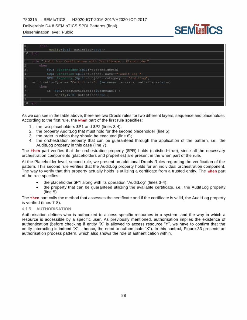
780315 — SEMIoTICS — H2020-IOT-2016-2017/H2020-IOT-2017
Deliverable D4.8 SEMIoTICS SPDI Patterns (final)
Dissemination level: Public
88
8. then
9. modify($pr2){satisfied=true};
10. End
1. rule " Audit Log Verification with Certificate - Placeholder" 2. when
3. $P1: Placeholder($pl1:=placeholderid)
4. $Op: Operation($pl1:=subject, name==" Audit Log ") 5. $PR: Property ($pl1:=subject, category == "AuditLog",
verificationType == "Certificate", $vermeans := means, satisfied==false)
6. then
7. if ($PR.checkCertificate($vermeans)) {
8. modify($PR){satisfied=true};
9. }
10. end
As we can see in the table above, there are two Drools rules for two different layers, sequence and placeholder. According to the first rule, the when part of the first rule specifies:
1. the two placeholders $P1 and $P2 (lines 3-4); 2. the property AuditLog that must hold for the second placeholder (line 5); 3. the order in which they should be executed (line 6); 4. the orchestration property that can be guaranteed through the application of the pattern, i.e., the
AuditLog property in this case (line 7).
The then part verifies that the orchestration property ($PR) holds (satisfied=true), since all the necessary orchestration components (placeholders and properties) are present in the when part of the rule.
At the Placeholder level, second rule, we present an additional Drools Rules regarding the verification of the pattern. This second rule verifies that the AuditLog property holds for an individual orchestration component. The way to verify that this property actually holds is utilizing a certificate from a trusted entity. The when part of the rule specifies:
• the placeholder $P1 along with its operation “AuditLog” (lines 3-4);
• the property that can be guaranteed utilizing the available certificate, i.e., the AuditLog property (line 5)
The then part calls the method that assesses the certificate and if the certificate is valid, the AuditLog property is verified (lines 7-8).
AUTHORISATION
Authorisation defines who is authorized to access specific resources in a system, and the way in which a resource is accessible by a specific user. As previously mentioned, authorisation implies the existence of authentication (before checking if entity “X” is allowed to access resource “Y”, we have to confirm that the entity interacting is indeed “X” – hence, the need to authenticate “X”). In this context, Figure 33 presents an authorisation process pattern, which also shows the role of authentication within.

780315 — SEMIoTICS — H2020-IOT-2016-2017/H2020-IOT-2017
Deliverable D4.8 SEMIoTICS SPDI Patterns (final)
Dissemination level: Public
89
FIGURE 33. AUTHORISATION PROCESS PATTERN (SOURCE: DIAMANTOPOULOU ET AL. [60])
We consider Authorisation as a property that is referred to a high-level problem and depends on specific patterns, creating the context for them. Two patterns can be utilized for achieving Authorisation, SingleAccessPont and AuthorisationEnforcer. The relationships of Authorisation with the specific patterns is depicted in Figure 34, in the form of a graph.
FIGURE 34. AUTHORISATION GRAPH
Authorisation can be expressed as a Drools rule, depicted in Table 24. The when part defines the sequence for which the Authorisation property needs to be checked if it holds and the property itself. The then part creates new properties for the components of the sequence in question. The SingleAccessPont and AuthorisationEnforcer properties are created for the components of the sequence that own an interface operationType.
TABLE 24. AUTHORISATION PATTERN IN DROOLS RULE
1. rule "Availability - Sequence"
2. when
3. $s: Sequence($sId:=id, $pA:=placeholdera, $pB:=placeholderb, $Link:=link)
4. Property($sId:=subject, category=="Availability", satisfied==false)
5. Then
6. if ($pA.hasOperationType("interface")) {
7. insert(new Property($pA:=subject, category=="SingleAccessPoint", satisfied==false);

780315 — SEMIoTICS — H2020-IOT-2016-2017/H2020-IOT-2017
Deliverable D4.8 SEMIoTICS SPDI Patterns (final)
Dissemination level: Public
90
8. insert(new Property($pA:=subject, category=="AuthorisationEnforcer", satisfied==false);
9. }
10. if ($pA.hasOperationType("interface")) {
11. insert(new Property($pB:=subject, category=="SingleAccessPoint", satisfied==false);
12. insert(new Property($pB:=subject, category=="AuthorisationEnforcer", satisfied==false);
13. }
14. end
SINGLE ACCESS POINT PATTERN DEFINITION
If you need to provide external access to a system, but want to protect it from misuse or damage, define a Single Access Point [36] that grants or denies entry to the system after checking the client requiring access. The Single Access Point is easy to apply, defines a clear entry point to the system, and can be assessed when implementing the desired security policy. Single Access Point enforces the overall system confidentiality.
Concrete implementations are called Login Window, Guard Door, or Validation Screen. The client logs in at the single access point and then uses the protected system (Figure 35).
FIGURE 35. SINGLE ACCESS POINT SEQUENCE DIAGRAM (SOURCE: SCHUMACHER ET AL. [36])
As it is already depicted in Figure 9, the Confidentiality Pattern graph, Single Access Point can itself be considered as a pattern that creates the context for other pore-specific patterns to solve lower level problems. In the Confidentiality graph we can see a number of patterns below Single Access Point. As an entry point is created, it can be used for the enforcement of different policies such as authentication, authorisation, validity of incoming data, known offenders and replay policies. If the user is interested only for authentication, the Authentication Enforcer Pattern enforces the authentication policies, using potentially yet other patterns. Authorisation Enforcer defines and enforces the authorisation policies. Intercepting Validator Pattern scans and validates data passed in for malicious code or malformed content. Network Address Blacklist is used to keep track of network addresses (IP addresses) that are the sources of hacking attempts and other mischief. These more specific patterns are described below in the document.
PATTERN SPECIFICATION RULE
Let us assume that we need to verify if the SingleAccessPoint property holds for the orchestration in Figure 36.

780315 — SEMIoTICS — H2020-IOT-2016-2017/H2020-IOT-2017
Deliverable D4.8 SEMIoTICS SPDI Patterns (final)
Dissemination level: Public
91
FIGURE 36. SINGLE ACCESS POINT SEQUENCE
The sequence above can be described using the pattern language created in SEMIoTICS as depicted below:
1. ORCH “Single Access Point”
2. Placeholder (A, “1st placeholder”)
3. Placeholder (B, “2nd placeholder”)
4. Operation (Op1, subject=B, operationType==“Interface”) 5. Link (L1, A, B)
6. Sequence (S1, A, B, L1)
7. Property (Pr, subject=S1, category=SingleAccessPoint, satisfied==false)
Based on the above, the Single Access Point pattern can be represented in Drools as shown in Table 25.
TABLE 25. SINGLE ACCESS POINT PATTERN AS DROOLS RULES
1. rule " Single Access Point Verification - Sequence" 2. when
3. $P1: Placeholder($pl1:=placeholderid)
4. $P2: Placeholder($pl2:=placeholderid)
5. $PR1: Property ($pl2:=subject, category=="SingleAccessPoint", satisfied==true)
6. $ORCH: Sequence ($seq:=placeholderid, $pl1:=placeholdera, $pl2:=placeholderb)
7. $PR2: Property ($seq:=subject, category=="SingleAccessPoint", satisfied==false)
8. Then
9. if ($P2.hasOneInterface) {
10. modify($PR2){satisfied=true}; 11. } 12. End
1. rule "Single Access Point Verification with Certificate - Placeholder"
2. when
3. $P1: Placeholder($pl1:=placeholderid)
4. $Op: Operation($pl1:=subject, name=="Interface")
5. $PR: Property ($pl1:=subject, category == "SingleAccessPoint",
verificationType == "Certificate", $vermeans := means, satisfied==false)
6. then
7. if ($PR.checkCertificate($vermeans)) {
8. modify($PR){satisfied=true};
9. }

780315 — SEMIoTICS — H2020-IOT-2016-2017/H2020-IOT-2017
Deliverable D4.8 SEMIoTICS SPDI Patterns (final)
Dissemination level: Public
92
10. end
As we can see in the table above, there are two Drools rules for two different layers, sequence and placeholder. According to the first rule, the when part of the first rule specifies:
1. the two placeholders $P1 and $P2 of the Single Access Point pattern (lines 3-4); 2. the property SingleAccessPoint that must hold for the second placeholder (line 5); 3. the order in which they should be executed (line 6); 4. the orchestration property that can be guaranteed through the application of the pattern, i.e., the
SingleAccessPoint property in this case (line 7).
The then part verifies that the orchestration property ($PR) holds (satisfied=true), since all the necessary orchestration components (placeholders and properties) are present in the when part of the rule.
At the Placeholder level, second rule, we present an additional Drools Rules regarding the verification of the pattern. This second rule verifies that the SingleAccessPoint property holds for an individual orchestration component. The way to verify that this property actually holds is utilizing a certificate from a trusted entity. The when part of the rule specifies:
1. the placeholder $P1 along with its operation “Interface” (lines 3-4); 2. the property that can be guaranteed utilizing the available certificate, i.e., the SingleAccessPoint
property (line 5)
The then part calls the method that assesses the certificate and if the certificate is valid, the SingleAccessPoint property is verified (lines 7-8).
AUTHORISATION ENFORCER PATTERN DEFINITION
Authorisation Enforcer [36] describes who is authorized to access specific resources in a system, in an environment in which we have resources whose access needs to be controlled. It indicates, for each active entity that can access resources, which resources it can access, and how it can access them.
As depicted in Figure 37, the Subject class describes an active entity that attempts to access a resource (Protection Object) in some way. The ProtectionObject class represents the resource to be protected. The association between the subject and the object defines an authorisation, from which the pattern gets its name. The association class Right describes the access type (for example, read, write) the subject is allowed to perform on the corresponding object. Through this class one can check the rights that a subject has on some object, or who is allowed to access a given object.
FIGURE 37. AUTHORISATION ENFORCER PATTERN (SOURCE: SCHUMACHER ET AL. [36])
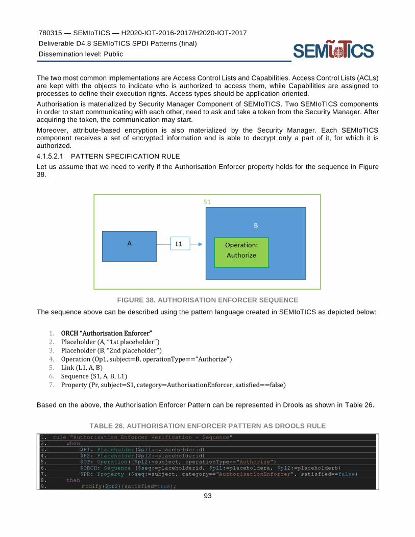
780315 — SEMIoTICS — H2020-IOT-2016-2017/H2020-IOT-2017
Deliverable D4.8 SEMIoTICS SPDI Patterns (final)
Dissemination level: Public
93
The two most common implementations are Access Control Lists and Capabil ities. Access Control Lists (ACLs) are kept with the objects to indicate who is authorized to access them, while Capabilities are assigned to processes to define their execution rights. Access types should be application oriented.
Authorisation is materialized by Security Manager Component of SEMIoTICS. Two SEMIoTICS components in order to start communicating with each other, need to ask and take a token from the Security Manager. After acquiring the token, the communication may start.
Moreover, attribute-based encryption is also materialized by the Security Manager. Each SEMIoTICS component receives a set of encrypted information and is able to decrypt only a part of it, for which it is authorized.
PATTERN SPECIFICATION RULE
Let us assume that we need to verify if the Authorisation Enforcer property holds for the sequence in Figure 38.
FIGURE 38. AUTHORISATION ENFORCER SEQUENCE
The sequence above can be described using the pattern language created in SEMIoTICS as depicted below:
1. ORCH “Authorisation Enforcer”
2. Placeholder (A, “1st placeholder”)
3. Placeholder (B, “2nd placeholder”)
4. Operation (Op1, subject=B, operationType==“Authorize”) 5. Link (L1, A, B)
6. Sequence (S1, A, B, L1)
7. Property (Pr, subject=S1, category=AuthorisationEnforcer, satisfied==false)
Based on the above, the Authorisation Enforcer Pattern can be represented in Drools as shown in Table 26.
TABLE 26. AUTHORISATION ENFORCER PATTERN AS DROOLS RULE
1. rule "Authorisation Enforcer Verification - Sequence"
2. when
3. $P1: Placeholder($pl1:=placeholderid)
4. $P2: Placeholder($pl2:=placeholderid)
5. $OP: Operation(($pl2:=subject, operationType=="Authorize”)
6. $ORCH: Sequence ($seq:=placeholderid, $pl1:=placeholdera, $pl2:=placeholderb)
7. $PR: Property ($seq:=subject, category=="AuthorisationEnforcer", satisfied==false)
8. then
9. modify($pr2){satisfied=true};
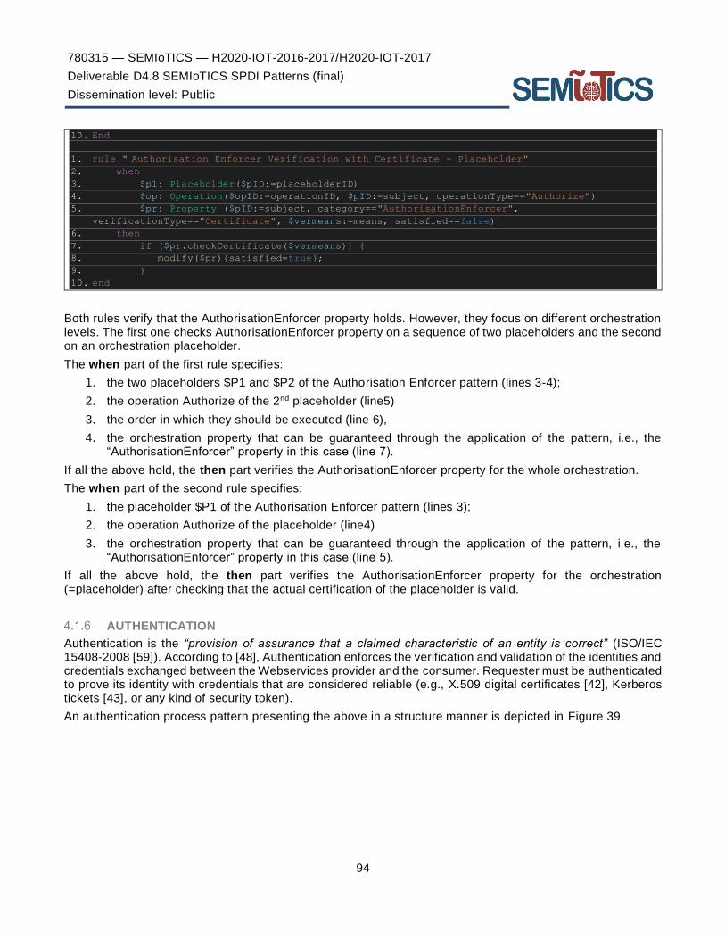
780315 — SEMIoTICS — H2020-IOT-2016-2017/H2020-IOT-2017
Deliverable D4.8 SEMIoTICS SPDI Patterns (final)
Dissemination level: Public
94
10. End
1. rule " Authorisation Enforcer Verification with Certificate - Placeholder" 2. when
3. $p1: Placeholder($pID:=placeholderID)
4. $op: Operation($opID:=operationID, $pID:=subject, operationType=="Authorize")
5. $pr: Property ($pID:=subject, category=="AuthorisationEnforcer",
verificationType=="Certificate", $vermeans:=means, satisfied==false)
6. then
7. if ($pr.checkCertificate($vermeans)) {
8. modify($pr){satisfied=true};
9. }
10. end
Both rules verify that the AuthorisationEnforcer property holds. However, they focus on different orchestration levels. The first one checks AuthorisationEnforcer property on a sequence of two placeholders and the second on an orchestration placeholder.
The when part of the first rule specifies:
1. the two placeholders $P1 and $P2 of the Authorisation Enforcer pattern (lines 3-4);
2. the operation Authorize of the 2nd placeholder (line5)
3. the order in which they should be executed (line 6),
4. the orchestration property that can be guaranteed through the application of the pattern, i.e., the “AuthorisationEnforcer” property in this case (line 7).
If all the above hold, the then part verifies the AuthorisationEnforcer property for the whole orchestration.
The when part of the second rule specifies:
1. the placeholder $P1 of the Authorisation Enforcer pattern (lines 3);
2. the operation Authorize of the placeholder (line4)
3. the orchestration property that can be guaranteed through the application of the pattern, i.e., the “AuthorisationEnforcer” property in this case (line 5).
If all the above hold, the then part verifies the AuthorisationEnforcer property for the orchestration (=placeholder) after checking that the actual certification of the placeholder is valid.
AUTHENTICATION
Authentication is the “provision of assurance that a claimed characteristic of an entity is correct” (ISO/IEC 15408-2008 [59]). According to [48], Authentication enforces the verification and validation of the identities and credentials exchanged between the Webservices provider and the consumer. Requester must be authenticated to prove its identity with credentials that are considered reliable (e.g., X.509 digital certificates [42], Kerberos tickets [43], or any kind of security token).
An authentication process pattern presenting the above in a structure manner is depicted in Figure 39.

780315 — SEMIoTICS — H2020-IOT-2016-2017/H2020-IOT-2017
Deliverable D4.8 SEMIoTICS SPDI Patterns (final)
Dissemination level: Public
95
FIGURE 39. AUTHENTICATION PROCESS PATTERN (SOURCE: DIAMANTOPOULOU ET AL. [60])
It can be possible to deploy mutual authentication mechanisms where credentials are exchanged and validate them before initiating the communication. In that way risks (man-in-the-middle, identity spoofing, and message-replay attacks) are alleviated and mitigated associated.
Let us assume that there is a need to verify that Authentication property holds for a sequence of two placeholders, connected by a link. Such a sequence can be described in the pattern language as shown below.
1. ORCH “Integrity”
2. Placeholder (A, “1st placeholder”)
3. Placeholder (B, “2nd placeholder”)
4. Link (L1, A, B)
5. Sequence (S1, A, B, L1)
6. Property (Pr, subject=S1, category=Integrity, satisfied==false)
Based on the above, Authentication can be expressed as a Drools rule, depicted in Table 27. The when part defines the sequence for which the Authentication property needs to be checked if it holds and the property itself. The then part creates new properties for the components of the sequence in question.
So, AuthenticationEnforcer, AuthenticationSession, Blacklist and AccountLockout properties are created for the two placeholders of the sequence. Finally, a AuthenticatedChannel property is created for the link between the two placeholders.
TABLE 27. AUTHENTICATION PATTERN IN DROOLS RULE
1. rule "Integrity - Sequence"
2. when
3. $s: Sequence($sId:=id, $pA:=placeholdera, $pB:=placeholderb, $Link:=link)
4. Property($sId:=subject, category=="Integrity", satisfied==false)
5. Then

780315 — SEMIoTICS — H2020-IOT-2016-2017/H2020-IOT-2017
Deliverable D4.8 SEMIoTICS SPDI Patterns (final)
Dissemination level: Public
96
6. insert(new Property($pA:=subject, category=="AuthenticationEnforcer", satisfied==false);
7. insert(new Property($pA:=subject, category=="AuthenticatedSession", satisfied==false);
8. insert(new Property($pA:=subject, category=="Blacklist", satisfied==false);
9. insert(new Property($pA:=subject, category=="AccountLockout", satisfied==false);
10. insert(new Property($pB:=subject, category=="AuthenticationEnforcer", satisfied==false);
11. insert(new Property($pB:=subject, category=="AuthenticatedSession", satisfied==false);
12. insert(new Property($pB:=subject, category=="Blacklist", satisfied==false);
13. insert(new Property($pB:=subject, category=="AccountLockout", satisfied==false);
14. insert(new Property($Link:=subject, category=="AuthenticatedChannel", satisfied==false);
15. end
AUTHENTICATION ENFORCER PATTERN DEFINITION
Operating systems have legitimate users that use it to host their files. However, there is no way to make sure that a user who is logged in is a legitimate user. Users can impersonate others and gain illegal access to their files. Authentication Enforcer addresses the problem of how to verify that a subject is who it says it is.
A Subject, typically a user, requests access to system resources. The Authentication Enforcer receives this request and applies a protocol using some Authentication Information. If the authentication is successful, the Authentication Enforcer creates a Proof of Identity, which can be explicit, for example a token, or implicit (see Figure 40).
Most commercial operating systems use passwords to authenticate their users.
FIGURE 40. AUTHENTICATION ENFORCER CLASS DIAGRAM (SOURCE: SCHUMACHER ET AL. [36])
The implementation of such a pattern includes: i) the definition of the authentication requirements (number of users, degree of security, etc.); ii) the selection of the authentication approach (e.g. the use of passwords); and iii) the build of the authentication information.
The Authentication Enforcer allows user data to be protected from unauthorized disclosure. The Authentication Enforcer can itself be considered as a pattern that creates the context for other pore specific patterns to solve lower level problems. It creates an Authentication Session and acts as an enforcement point for the Account Lockout and Blacklist patterns.
PATTERN SPECIFICATION RULE

780315 — SEMIoTICS — H2020-IOT-2016-2017/H2020-IOT-2017
Deliverable D4.8 SEMIoTICS SPDI Patterns (final)
Dissemination level: Public
97
Let us assume that we need to verify if the Authentication Enforcer property holds for the sequence in Figure 41.
FIGURE 41. AUTHENDICATION ENFORCER SEQUENCE
The sequence above can be described using the pattern language created in SEMIoTICS as depicted below:
1. ORCH “Authentication Enforcer”
2. Placeholder (A, “1st placeholder”)
3. Placeholder (B, “2nd placeholder”)
4. Operation (Op1, subject=B, operationType==“Authenticate”)
5. Link (L1, A, B)
6. Sequence (S1, A, B, L1)
7. Property (Pr, subject=S1, category=AuthenticationEnforcer, satisfied==false)
Based on the above, the Authentication Enforcer pattern can be represented in Drools as shown in Table 28.
The when part of the first rule specifies:
1. the two placeholders $P1 and $P2 of the Authentication Enforcer pattern (lines 3-4); 2. the order in which they should be executed (line 5), 3. the orchestration property that can be guaranteed through the application of the pattern, i.e., the
“AuthenticationEnforcer” property in this case (line 6)
The then part generates the security properties that, if satisfied by the activity placeholders of the pattern’s orchestration, would make the orchestration to satisfy the orchestration property. In this specific case, placeholders that constitute the sequence and have an operation that checks credentials (hasOperation("interface")) should satisfy the AuthenticationEnforcer, AuthenticatedSession, Account Lockout and NetwokAddressBlacklist properties (lines 8-17). Each of these properties refers to the patterns that are below Authentication Enforcer in the Confidentiality Pattern graph.
TABLE 28. AUTHENTICATION ENFORCER PATTERN AS DROOLS RULE
1. rule "Authentication Enforcer (Sequence)"
2. when
3. $P1: Placeholder($pl1:=placeholderid)
4. $P2: Placeholder($pl2:=placeholderid)
5. $ORCH: Sequence ($seq:=placeholderid, $pl1:=placeholdera, $pl2:=placeholderb)
6. $PR: Property ($seq:=subject, category=="AuthenticationEnforcer", satisfied==false)
7. then
8. if ($P1.hasOperation("interface")) {
9. insert(new Property($P1, "AuthenticationEnforcer", false));
10. insert(new Property($P1, "AuthenticatedSession", false));

780315 — SEMIoTICS — H2020-IOT-2016-2017/H2020-IOT-2017
Deliverable D4.8 SEMIoTICS SPDI Patterns (final)
Dissemination level: Public
98
11. insert(new Property($P1, "AccountLockout", false)); 12. insert(new Property($P1, "Blacklist", false)); 13. } 14. if ($P2.hasOperation("interface")) { 15. insert(new Property($P2, "AuthenticationEnforcer", false)); 16. insert(new Property($P2, "AuthenticatedSession", false)); 17. insert(new Property($P2, "AccountLockout", false)); 18. insert(new Property($P1, "Blacklist", false)); 19. } 20. End
1. rule " Authentication Enforcer Verification with Certificate - Placeholder" 2. when
3. $p1: Placeholder($pID:=placeholderID)
4. $op: Operation($opID:=operationID, $pID:=subject, operationType=="Authenticate")
5. $pr: Property ($pID:=subject, category=="AuthenticationEnforcer",
verificationType=="Certificate", $vermeans:=means, satisfied==false)
6. then
7. if ($pr.checkCertificate($vermeans)) {
8. modify($pr){satisfied=true};
9. }
10. end
The when part of the second rule specifies:
1. the placeholder $P1 of the Authorisation Enforcer pattern (lines 3); 2. the operation Authorize of the placeholder (line4) 3. the orchestration property that can be guaranteed through the application of the pattern, i.e., the
“AuthorisationEnforcer” property in this case (line 5).
If all the above hold, the then part verifies the AuthorisationEnforcer property for the orchestration (= placeholder) after checking that the actual certification of the placeholder is valid.
AUTHENTICATED CHANNEL PATTERN DEFINITION
Authenticated channel ensures authenticity on the channel level. According to [44], a secure authenticated channel should have the following characteristics:
1. mutual authentication of the peers; 2. key confirmation (at least one peer is able to verify that the common secret indeed is common); 3. forward secrecy (old session keys cannot be calculated even when long-term secret keys (such as
certificate Secret keys are known).
Implementation examples of Authenticated channel are Kerberos authentication [43], two-way SSL authentication [45].
PATTERN SPECIFICATION RULE
Let us assume that we need to verify if the AuthenticatedChannel property holds for the sequence in Figure 42.

780315 — SEMIoTICS — H2020-IOT-2016-2017/H2020-IOT-2017
Deliverable D4.8 SEMIoTICS SPDI Patterns (final)
Dissemination level: Public
99
FIGURE 42. AUTHENTICATED CHANNEL SEQUENCE
The sequence above can be described using the pattern language created in SEMIoTICS as depicted below:
1. ORCH “Authenticated Channel”
2. Placeholder (A, “1st placeholder”) 3. Placeholder (B, “2nd placeholder”)
4. Link (L1, A, B)
5. Operation (Op1, subject=L1, operationType==“Authentication”)
6. Sequence (S1, A, B, L1) 7. Property (Pr, subject=S1, category=AuthenticatedChannel, satisfied==false)
Based on the above, the Authenticated Channel can be represented in Drools as shown in Table 29. The rule in this table is a verification rule, which verifies that the AuthenticatedChannel property holds for a link. The way to verify that this property actually holds is utilizing a certificate from a trusted entity.
The when part of the rule specifies:
1. the link $L (line 3); 2. the property that can be guaranteed utilizing the available certificate, i.e., the
AuthenticatedChannel property (line 4)
The then part calls the method that assesses the certificate and if the certificate is valid, the AuthenticatedChannel property is verified (lines 6-8).
TABLE 29. AUTHENTICATED CHANNEL PATTERN AS DROOLS RULE
1. rule "Authenticated Channel Verification with Certificate - Link"
2. when
3. $L: Link($linkId:=linkid)
4. $PR: Property ($linkId:=subject, category == "AuthenticatedChannel",
verificationType == "Certificate", $vermeans := means, satisfied==false)
5. then
6. if ($PR.checkCertificate($vermeans)) {
7. modify($PR){satisfied=true};
8. }
9. end
ACCOUNT LOCKOUT PATTERN DEFINITION
Account Lockout protects user accounts from automated password-guessing attacks, by implementing a limit on incorrect password attempts before further attempts are disallowed (see Figure 43).
The steps of an authentication attempt are presented below:
1. The client is provided with a transaction form or login screen requiring both a username and a password.
2. The user provides the username and password and submits the request for a protected resource.

780315 — SEMIoTICS — H2020-IOT-2016-2017/H2020-IOT-2017
Deliverable D4.8 SEMIoTICS SPDI Patterns (final)
Dissemination level: Public
100
3. The mediator checks the username, and if valid retrieves the account information. If the username is invalid, return a generic failed login message.
4. The mediator checks if this user’s account is locked out (number of successive failed logins exceeds the threshold) and not yet cleared (last failed login time + reset duration > current time). If locked, return a generic failed login message.
5. If the user’s account is not locked, the mediator checks the validity of the password. If the password is not valid, increment the number of failed login attempts against the account, and set the last failed login time to the current time. Return a generic failed login message.
6. If the password is valid, reset the number of failed logins to 0, and execute the request against the protected resource.
FIGURE 43. ACCOUNT LOCKOUT PATTERN (SOURCE: KIENZEL ET AL. [35])
Let us consider:
• PAincorrect := number of incorrect password attempts
• TH := predefined threshold for maximum incorrect password attempts
• AS := account status (unlocked or locked)
• RD := reset duration
• CT := current time
• LFLT := last failed login time
Based on the above specification we can define a generic pattern for Account Lockout as the following:
(PAincorrect >= TH) & (LFLT + RD > CΤ) → AS=locked
(PAincorrect >= TH) & (LFLT + RD < CT) → AS=unlocked
PATTERN SPECIFICATION RULE
Let us assume that we need to verify if the AccountLockout property holds for the orchestration in Figure 44.

780315 — SEMIoTICS — H2020-IOT-2016-2017/H2020-IOT-2017
Deliverable D4.8 SEMIoTICS SPDI Patterns (final)
Dissemination level: Public
101
FIGURE 44. ACCOUNT LOCKOUT ORCHESTRATION
1. ORCH “Account Lockout”
2. Placeholder (A, “1st placeholder”)
3. Placeholder (M, “Mediator”)
4. Operation (Op1, subject=M, operationType==“Lockout”)
5. Placeholder (B, “2nd placeholder”)
6. Link (L1, A, M)
7. Sequence (S1, A, M, L1)
8. Placeholder (AI, “Account Information”)
9. Link (L2, S1, B) 10. Link (L2, S1, AI)
11. Choice (Ch, S1, B, AI, L1, L2)
12. Property (Pr, subject=Ch, category=AccountLockout, satisfied==false)
Based on the above, the Account Lockout pattern can be represented in Drools as shown in Table 30.
The when part of the first rule specifies:
1. the placeholders $p1, $p2, $p3 and $p4 along with the property AccountLockout for $p2 ($pr1); 2. the order in which they should be executed ($s and $ch), 3. the orchestration property that can be guaranteed through the application of the pattern, i.e., the
AccountLockout property in this case ($pr2).
The then part verifies that the orchestration property holds since every essential component is included in the when part (satisfied=true).
TABLE 30. ACCOUNT LOCKOUT PATTERN AS DROOLS RULES
1. rule "Account Lockout Verification"
2. when
3. $p1: Placeholder($pID1:=placeholderID)
4. $p2: Placeholder($pID2:=placeholderID)
5. $pr1: Property($pID2:=subject, category=="AccountLockout", satisfied==true)
6. $p3: Placeholder($pID3:=placeholderID)
7. $p4: Placeholder($pID4:=placeholderID)
8. $s: Sequence($sID:=id, $pID1:=placeholderA, $pID2:=placeholderB)
9. $ch: Choice($chID:=id, $sID:=placeholderA, $pID3:=placeholderB, $pID4:=placeholderC)
10. $pr2: Property($chID:=subject, category=="AccountLockout", satisfied==false)
11. then

780315 — SEMIoTICS — H2020-IOT-2016-2017/H2020-IOT-2017
Deliverable D4.8 SEMIoTICS SPDI Patterns (final)
Dissemination level: Public
102
12. modify($pr2){satisfied=true};
13. end
1. rule "Account Lockout Verification with Certificate - Placeholder"
2. when
3. $p1: Placeholder($pID:=placeholderID)
4. $op: Operation($opID:=operationID, $pID:=subject, operationType=="Lockout")
5. $pr: Property ($pID:=subject, category=="AccountLockout", verificationType ==
"Certificate", $vermeans := means, satisfied==false)
6. then
7. if ($pr.checkCertificate($vermeans)) {
8. modify($pr){satisfied=true};
9. }
10. end
Moreover, the second Drools Rule verifies that the AccountLockout property holds for an individual orchestration component (placeholder). In this case, the way to verify that this property actually holds is utilizing a certificate from a trusted entity.
The when part of the rule specifies:
1. the placeholder $p1 along with its operation “Lockout”; 2. the property that can be guaranteed utilizing the available certificate, i.e., the Account Lockout property
in this case ($pr)
The then part calls the method that assesses the certificate and if the certificate is valid, the Account Lockout property is verified (satisfied=true).
AUTHENTICATED SESSION PATTERN DEFINITION
An Authenticated Session keeps track of a user’s authenticated identity through the duration of a Web session. A user is allowed to access multiple protected pages on the Web site authenticating him-/herself just once. It keeps track of the last page access time and causes the session to expire after a predetermined period of inactivity.
The Authenticated Session pattern caches the user’s authenticated identity on the server. As a result, the application is more confident that the user has not tampered with it. The only way that the authenticated identity session attribute can be set is if the user successfully authenticated to the authentication module. The Authenticated Session pattern utilizes existing session mechanisms to associate the client with a particular session.
The repeated authentication in this automated manner increases accountability. Confidentiality and Integrity protections of the system are increased consequently.
PATTERN SPECIFICATION RULE
Based on the above, the Authenticated Session pattern can be represented in Drools as shown in Table 31.

780315 — SEMIoTICS — H2020-IOT-2016-2017/H2020-IOT-2017
Deliverable D4.8 SEMIoTICS SPDI Patterns (final)
Dissemination level: Public
103
TABLE 31. AUTHENTICATION SESSIONS PATTERN AS DROOLS RULES
1. rule "Authenticated Session - Sequence"
2. when
3. $P1: Placeholder($pl1:=placeholderid)
4. $P2: Placeholder($pl2:=placeholderid)
5. $ORCH: Sequence ($seq:=placeholderid, $pl1:=placeholdera, $pl2:=placeholderb)
6. $PR: Property ($seq:=subject, category=="AuthenticatedSession", satisfied==false)
7. then
8. if ($P1.hasOperation("interface")) {
9. insert(new Property($P1, "AuthenticatedSession", false));
10. }
11. if ($P2.hasOperation("interface")) {
12. insert(new Property($P2, "AuthenticatedSession", false));
13. }
14. end
1. rule " Authenticated Session Verification with Certificate" 2. when
3. $P1: Placeholder($pl1:=placeholderid)
4. $Op: Operation($pl1:=subject, name=="interface")
5. $PR: Property ($pl1:=subject, category == "AuthenticatedSession", verificationType ==
"Certificate", $vermeans := means, satisfied==false)
6. then
7. if ($PR.checkCertificate($vermeans)) {
8. modify($PR){satisfied=true};
9. }
10. end
The when part of the first rule specifies:
1. the two placeholders $P1 and $P2 of the Authenticated Session pattern (lines 3-4); 2. the order in which they should be executed (line 5), 3. the orchestration property that can be guaranteed through the application of the pattern, i.e., the
AuthenticatedSession property in this case (line 6).
The then part generates the security properties that, if satisfied by the activity placeholders of the pattern’s orchestration, would make the orchestration to satisfy the orchestration property. Each of the placeholders that has an operation that checks credentials (hasOpertionType(“interface”)) should satisfy the AuthenticatedSession property (lines 8-13).
The second Rule is a verification rule and verifies that the AuthenticatedSession property holds for an individual orchestration component (Placeholder). In this case, in order to verify that this property holds, we utilize a certificate from a trusted entity.
The when part of the rule specifies:
1. the placeholder $P1 along with its operation “interface” (lines 3-4); 2. the property that can be guaranteed utilizing the available certificate, i.e., the AuthenticatedSession
property in this case (line 5)
The then part calls the method that assesses the certificate and if the certificate is valid, the AuthenticatedSession property is verified (lines 7-9).
BLACKLIST PATTERN DEFINITION
A Blacklist (see Figure 45) is used to keep track of network addresses (IP addresses) that are the sources of hacking attempts and other mischief. Any requests originating from an address on the blacklist are simply ignored.

780315 — SEMIoTICS — H2020-IOT-2016-2017/H2020-IOT-2017
Deliverable D4.8 SEMIoTICS SPDI Patterns (final)
Dissemination level: Public
104
Blocking mechanism at the network level: In normal circumstances, a client that is not on the blacklist will make a benign request of the server. The blocking mechanism will let the request pass, and the server will respond with normal functionality. When a non-blacklisted client makes a suspicious request, the server will keep a record of the network address and the nature of the request. If the request is sufficiently egregious (or the last in a sequence of requests that exceeds some predefined threshold of tolerance) the server will request that the address be blacklisted. The blacklist will configure the blocking mechanism to deny further requests from that address.
When a blacklisted client makes a request of any sort, the blocking mechanism will simply drop the request on the floor. Optionally, it may log the request for administrator audit.
After a period of inactivity from a blacklisted address, the blacklist mechanism will remove the address from the blacklist and configure the blocking mechanisms to allow further requests from that address. Alternately, this can occur because of manual administrator intervention, possibly at a user’s request.
FIGURE 45. BLACKLIST IMPLEMENTATION (SOURCE: KIENZEL ET AL. [35])
Blocking mechanism within the application: In such a case, the application would be structured roughly similar to the figure above. When a request is received, it is first checked against the blacklist before being dispatched to the appropriate page.
Let us consider:
• RT := request threat
• TH := predefined threshold of tolerance
• AS := address status (blacklisted or whitelisted)
• RD := reset duration
• CT := current time
• LRTA := last request time from address A Based on the above specification we can define a generic pattern for Account Lockout as the following:
RT >= TH → AS= blacklisted
LRTA + RD < CT → AS= whitelisted
If Blacklist is implemented effectively, it enhances system confidentiality and integrity, since it will dissuade or prevent attempts to misuse the system. In the case that the pattern is ineffective, it will not adversely affect these properties.

780315 — SEMIoTICS — H2020-IOT-2016-2017/H2020-IOT-2017
Deliverable D4.8 SEMIoTICS SPDI Patterns (final)
Dissemination level: Public
105
PATTERN SPECIFICATION RULE
Let us assume that we need to verify if the Blacklist property holds for the orchestration in Figure 46.
FIGURE 46. BLACKLIST ORCHESTRATION
The sequence above can be described using the pattern language created in SEMIoTICS as depicted below:
1. ORCH “Blacklist”
2. Placeholder (A, “1st placeholder”) 3. Placeholder (BM, “Blocking Mechanism”)
4. Operation (Op1, subject=M, operationType==“Put in Blacklist”)
5. Placeholder (B, “2nd placeholder”) 6. Link (L1, A, BM) 7. Sequence (S1, A, BM, L1)
8. Placeholder (BL, “Blacklist”) 9. Link (L2, S1, B) 10. Link (L2, S1, BL) 11. Choice (Ch, S1, B, BL, L1, L2) 12. Property (Pr, subject=Ch, category=Blacklist, satisfied==false)
Based on the above, the Blacklist Pattern can be represented in Drools as shown in Table 32.
TABLE 32. BLACKLIST PATTERN AS DROOLS RULE
1. rule "Blacklist Verification"
2. when
3. $p1: Placeholder($pID1:=placeholderID)
4. $p2: Placeholder($pID2:=placeholderID)
5. $pr1: Property($pID2:=subject, category=="Blacklist", satisfied==true)
6. $p3: Placeholder($pID3:=placeholderID)
7. $p4: Placeholder($pID4:=placeholderID)
8. $s: Sequence($sID:=id, $pID1:=placeholderA, $pID2:=placeholderB)
9. $ch: Choice($chID:=id, $sID:=placeholderA, $pID3:=placeholderB, $pID4:=placeholderC)
10. $pr2: Property($chID:=subject, category=="Blacklist", satisfied==false)
11. then
12. modify($pr2){satisfied=true};
13. end
1. rule "Blacklist Verification with Certificate - Placeholder"

780315 — SEMIoTICS — H2020-IOT-2016-2017/H2020-IOT-2017
Deliverable D4.8 SEMIoTICS SPDI Patterns (final)
Dissemination level: Public
106
2. when
3. $p1: Placeholder($pID:=placeholderID)
4. $op: Operation($opID:=operationID, $pID:=subject, operationType=="Put in Blacklist")
5. $pr: Property ($pID:=subject, category=="Blacklist", verificationType ==
"Certificate", $vermeans := means, satisfied==false)
6. then
7. if ($pr.checkCertificate($vermeans)) {
8. modify($pr){satisfied=true};
9. }
10. end
The when part of the first rule specifies:
1. the placeholders $p1, $p2, $p3 and $p4 along with the property Blacklist for $p2 ($pr1); 2. the order in which they should be executed ($s and $ch), 3. the orchestration property that can be guaranteed through the application of the pattern, i.e., the
Blacklist property in this case ($pr2).
The then part verifies that the orchestration property holds since every essential component is included in the when part (satisfied=true).
Moreover, the second Drools Rule verifies that the Blacklist property holds for an individual orchestration component (placeholder). In this case, the way to verify that this property actually holds is utilizing a certificate from a trusted entity.
The when part of the rule specifies:
1. the placeholder $P1 along with its operation “Lockout”; 2. the property that can be guaranteed utilizing the available certificate, i.e., the Blacklist property in this
case ($pr)
The then part calls the method that assesses the certificate and if the certificate is valid, the Blacklist property is verified (satisfied=true).
Privacy
Privacy, as already highlighted in subsection 2.2, is a complex topic with significant legal and regulatory implications. The latter comprise a dynamic landscape, as ever-stricter privacy laws are being introduced in many countries around the world, with the EU being at the forefront of such efforts, mainly through GDPR [4], and the push for “Privacy by design”.
There have been various efforts to provide architectural and design patterns for the protection of privacy (e.g., [49][52][53][54]) though these are significantly less common than other topics, such as patterns covering software development and cloud architectures, or even security properties (as the ones defined in subsection 4.1 above). Still, this is expected to improve as privacy comes into the limelight , being recognised as an important standalone requirement.
An important obstacle when defining privacy patterns is the fact that while the privacy properties themselves are relatively well understood, there is a lack of an established terminology for referring to some of the properties [55], and also a lack of a clear taxonomy in defining the relationships between said properties [56]. Therefore, a literature review reveals conflicting definitions of the terms, as well as their relationship, even among privacy-related standards. For example, some works group anonymity and pseudonymity together (e.g., [57]), while others highlight the significant differences between the two in terms of linkability (e.g., see Pfitzmann et al. [55] and ISO/IEC 29100:2011 [58]). Another example of such discrepancies is that some works group unobservability and undetectability (e.g., see ISO/IEC 15408-2:2008 [59] and Kalloniatis et al. [57]) while others differentiate between the two (e.g., Pfitzmann et al. [55] and Diamantopoulou et al. [60]).
Considering the above landscape and consolidating the various views, the work presented herein covers the eight key privacy concepts as identified and defined by the consensus of works in the area [55][57]-[63],

780315 — SEMIoTICS — H2020-IOT-2016-2017/H2020-IOT-2017
Deliverable D4.8 SEMIoTICS SPDI Patterns (final)
Dissemination level: Public
107
namely: i) Data Protection; ii) Authentication; iii) Authorisation; iv) Anonymity; v) Pseudonymity; vi) Unlinkability; vii) Undetectability, and; viii) Unobservability.
From the above, we can derive two subgroups of properties: properties (i)-(iii) are, in fact, security properties (which is expected, since security is required to achieve privacy, considering the need for protection of personal data), while properties (iv)-(viii) are solely privacy related. Thus, for the first group of properties we refer the reader to the analysis of the corresponding properties in subsection 4.1, while properties of the second group will be defined in the subsections that follow.
The subsections below also highlight enablers (typically referred to as Privacy Enabling Technologies – PETs – in the context of Privacy) allowing the satisfaction of said properties from an implementation perspective, while providing patterns for some characteristic examples of them. PETs are defined as “a system of ICT measures protecting informational privacy by eliminating or minimising personal data thereby preventing unnecessary or unwanted processing of personal data, without the loss of the functionality of the information system” [64][65]. In the context of this work, PETs can be considered as specific technological building blocks that can be used to implement a pattern.
It should be noted that anonymity, pseudonymity, unlinkability, undetectability and unobservability depend on the system/attacker model considered. Said model defines the capabilities of the attacker (if the attacker eavesdrops upon or controls the network and/or some of the endpoints, if the attacker is colluding with some of the senders or some of the receivers or third parties, and other such variations). A full coverage and analysis on the satisfaction of these properties under all envisioned cases is beyond the scope of the work presented herein, as it focuses on deriving practical patterns for designing, deploying and monitoring IoT orchestrations that integrate the PETs that can guarantee said privacy properties. For such a theoretical analysis we defer the reader to the rich literature on the matter (e.g., the seminal works of A. Pfitzmann [55][66][67] and other resources on the topic [61]).
The abovementioned privacy properties, concepts and related patterns, their relationships and the enabling patterns that will be provided herein, are depicted in the hierarchical graph of Figure 47.
FIGURE 47. HIERARCHICAL VIEW OF PRIVACY PROPERTIES, CONCEPTS AND ENABLING PATTERNS
ANONYMITY
Anonymity "ensures that a user may use a resource or service without disclosing the user's identity" (ISO/IEC 15408-2008 [59]). A definition more evidently considering the current legislative privacy landscape (e.g., GDPR), thus focusing on personally Identifiable Information (PII), states that “Anonymity is a characteristic of information that does not permit a personally identifiable information principal to be identified directly or indirectly” (ISO/IEC 29100:2011 [58]). Nevertheless, a more generic view of Anonymity is provided in the

780315 — SEMIoTICS — H2020-IOT-2016-2017/H2020-IOT-2017
Deliverable D4.8 SEMIoTICS SPDI Patterns (final)
Dissemination level: Public
108
following: "Anonymity of a subject means that the subject is not identifiable within a set of subjects, the anonymity set" [55], whereby "anonymity set" is the set of all possible subjects.
A formal definition of anonymity is as follows (originally defined in [67], adapted in [61]):
Let RU denote the event that an entity U (e.g., a user) performs a role R (e.g., as a sender or receiver of a message) during an event E (e.g., communication event, or a service access). Let A denote an attacker, and let NCA be the set of entities that are not cooperating with A.
An entity U is called anonymous in role R for an event E against an attacker A, if for each observation B that A can make, the following holds:
∀ U´ ∈ NCA: 0 < P(RU´ | B) < 1
A less strict requirement could be that the above relation does not have to hold for all but at least for most non-cooperating entities from the set NCA. However, anonymity for an entity U in the role R can only be guaranteed if the value P(RU | B) is not too close to the values 1 or 0. Thus, an additional requirement should be:
0 << 𝑃(𝑅𝑈 | 𝐵) << 1 [A <<B means that A is much smaller than B]
As mentioned above, anonymity also depends on the model considered, leading to different types of anonymity: Sender anonymity means the user is anonymous in her role as a sender (the receiver might not be), and vice versa for Receiver anonymity. This, elaborating on the above:
An entity U is defined as perfectly anonymous in role R for an event E against an attacker A, if for each observation B that A can make:
∀ U´ ∈ NCA: P(RU´) = P(RU´ | B)
That is, observations give an attacker no additional information.
Thus, in perfect sender (or receiver) anonymity, whereby the attacker cannot distinguish the situations in which a potential sender (receiver) actually sent (received) communications and those in which he did not .
As such, anonymity facilitates user access to services and resources without revealing their identity or other sensitive information (e.g., exact location), blocking tracking and profiling attempts. Nevertheless, some constraints have to be considered; e.g., strong anonymity implies a large anonymity set (i.e., a large set of users, which is not always possible), while strong anonymity also constrains the usability of data (e.g., location-based or personalised services cannot be as accurate).
A significant number of PETs can be leveraged to implement anonymity, as the development of anonymous communication networks (ACNs) comprises one of the most prominent areas of privacy-related research and development efforts. Solutions include the use of anonymizing proxies and trusted third parties (e.g. CATS10), Mix networks [68] (e.g., the Mixmaster anonymous remailer11), DC-nets [69], Onion Routing [70] (e.g., the Tor browser [71]), k-Anonymity [72], L-diversity [73] and t-Closeness [74] schemes (e.g., for location privacy [75]) and many others (see related works cited within this section).
MIX NETWORK PATTERN DEFINITION
The concept of Mix networks (often referred to as “Mix-Nets”) was introduced by D. Chaum [68] and has had very significant impact in the area of anonymous networking. It provides sender anonymity against the receiver (optionally recipient anonymity), as well as unlinkability of sender and receiver [61]. Combined with dummy traffic, they can also provide unobservability [55] (more on that in the subsections that follow). The popular concept of Onion Routing [70] is based on mixes but adds layered encryption.
10 https://www.custodix.com/index.php/cats 11 http://mixmaster.sourceforge.net/

780315 — SEMIoTICS — H2020-IOT-2016-2017/H2020-IOT-2017
Deliverable D4.8 SEMIoTICS SPDI Patterns (final)
Dissemination level: Public
109
FIGURE 48. SENDER ANONYMITY IN A MIX NETWORK (SOURCE: M. HAFIZ [51])
The concept, as shown in Figure 48 and Figure 49, relies on the existence of a chain of independent mix stations (or “mixes”) between senders and receivers. Said stations are responsible for mixing traffic from each user with traffic from other users, collecting and storing the user messages, decrypting and re-encrypting them (to change their appearance) and outputting them in a different order than the one received.
FIGURE 49. A MIX NETWORK HIDES THE RELATION BETWEEN INCOMING AND OUTGOING MESSAGES (SOURCE: S. FISCHER-HÜBNER [61])
PATTERN SPECIFICATION RULE
Let us assume that a node (let it be “A”) wants to send a message to another node (let it be “B”), and we want to ensure that anonymity is provided for this exchange. A process pattern that integrates a Mix network into the orchestration (resulting in a view similar to Figure 49) can be applied. In order to verify the anonymity property holds for the resulting orchestration (see Figure 50), the sequence can be described using the pattern language created in SEMIoTICS as follows:

780315 — SEMIoTICS — H2020-IOT-2016-2017/H2020-IOT-2017
Deliverable D4.8 SEMIoTICS SPDI Patterns (final)
Dissemination level: Public
110
1. ORCH “Mix-net” 2. Placeholder (A, “1st placeholder”) 3. Placeholder (M, “Mix-net”) 4. Operation (Op1, subject=M, operationType==“Anonymise”) 5. Placeholder (B, “2nd placeholder”) 6. Link (L1, A, M) 7. Sequence (S1, A, M, L1) 8. Link (L2, S1, B) 9. Sequence (S2, S1, B, L2)
10. Property (Pr, subject=S2, category=Anonymity, satisfied==false)
FIGURE 50. MIX NETWORK ANONYMISATION SEQUENCE
Based on the above, the Mix Network Pattern can be represented in Drools as shown in Table 33.
TABLE 33. MIX NETWORK ANONYMISATION AS DROOLS RULE
1. rule " Anonymisation - Sequence" 2. when
3. $P1: Placeholder($pl1:=placeholderid)
4. $P2: Placeholder($pl2:=placeholderid)
5. $PR1: Property($pl2:=subject, category=="Anonymity", satisfied==true)
6. $P3: Placeholder($pl3:=placeholderid)
7.
8. $s1: Sequence($sid1:=id, $pID1:=placeholderA, $pID2:=placeholderB)
9. $s2: Sequence($sid2:=id, $sID1:=placeholderA, $pID3:=placeholderB)
10. 11. $PR2: Property($sID2:=subject, category=="Anonymity", satisfied==false) 12. then 13. modify($PR2){satisfied=true}; 14. End
1. rule "" Anonymisation Verification with Certificate - Placeholder "
2. when
3. $P1: Placeholder($pID:=placeholderID)
4. $OP: Operation($opID:=operationID, $pID:=subject, operationType=="Anonymise")
5. $PR: Property ($pID:=subject, category=="Anonymity", verificationType ==
"Certificate", $vermeans := means, satisfied==false)
6. then
7. if ($PR.checkCertificate($vermeans)) {
8. modify($PR){satisfied=true};
9. }
10. end
As we can see in the table above, there are two Drools rules for two different layers, sequence and placeholder. According to the first rule, the when part of the first rule specifies:

780315 — SEMIoTICS — H2020-IOT-2016-2017/H2020-IOT-2017
Deliverable D4.8 SEMIoTICS SPDI Patterns (final)
Dissemination level: Public
111
1. the three placeholders $P1, $P2 and $P3 of the pattern (lines 3-4 and 6); 2. the property “Anonymity” that must hold for the second placeholder (line 5); 3. the order in which they should be executed (lines 8 and 9); 4. the orchestration property that can be guaranteed through the application of the pattern, i.e., the
Anonymity property in this case (line 11).
The then part verifies that the orchestration property ($PR) holds (satisfied=true), since all the necessary orchestration components (placeholders and properties) are present in the when part of the rule.
At the Placeholder level (second rule), we present an additional Drools Rule regarding the verification of the pattern. This second rule verifies that the Anonymity property holds for an individual orchestration component. The way to verify that this property actually holds is utilizing a certificate from a trusted entity. The when part of the rule specifies:
1. the placeholder $P1 along with its operation “Anonymise” (lines 3-4); 2. the property that can be guaranteed utilizing the available certificate, i.e., the Anonymity property (line
5)
The then part calls the method that assesses the certificate and if the certificate is valid, the Anonymity property is verified (lines 7-8).
ORCHESTRATION IDENTIFIABILITY CHECK PATTERN DEFINITION
In order to guarantee anonymity and unlinkability of entities, not only components that form the service should be checked for these properties but also their composition. At each layer of composition, the data union that the layer produces should be evaluated, since the privacy properties can be violated by correlation of data from different sources In this context, a privacy pattern to check the identifiability is provided herein (identifiability being defined as an opposite of anonymity and unlinkability, as in [55]).
More specifically, let us consider the composition of a service of two components.
FIGURE 51. ORCHESTRATION IDENTIFIABILITY PATTERN EXAMPLE
Let us assume that for each x in {A, B, C}
• OUTX are the sets of outputs of x
• INX are the sets of inputs of x
• EX=INX ∪ OUTX • VX and CX are two disjoint subsets of EX which partition it into public parts VX and confidential parts CX
• L is a corpus of sets that are pre-defined that expose privacy
Then in order the composition to satisfy the privacy requirements, the following properties must hold:

780315 — SEMIoTICS — H2020-IOT-2016-2017/H2020-IOT-2017
Deliverable D4.8 SEMIoTICS SPDI Patterns (final)
Dissemination level: Public
112
a. VA ∩ L =⌀ b. VB ∩ L =⌀ c. VC ∩ L =⌀
Moreover, when data are at rest (i.e. in storage) we should take precautions that:
d. (VA ∪ VB ∪ VC) ∩ L =⌀
Still, the following properties should also hold:
e. (VA ∪ VB) ⊆ VC f. (VA ∪ VB) ∩ CC =⌀
As an example, let us assume that there are two components A and B that we want to use to create a service C. Moreover, a set L that exposes users privacy is L={(name, location), (name, medical_condition)}; i.e., we do not want a service that exposes a person’s name along with her location and/or her medical conditions.
Component A publicly sends the user’s ID, environmental temperature and location, while component B publicly sends the user’s name, user’s ID and the hum idity of the environment
In this case, Req(A, Privacy) is validated as True (since OUTA ∩ L =⌀), and also Req(B, Privacy) is validated as True (since OUTB ∩ L =⌀).
Nevertheless, the composition of A and B to form C, as in Figure 51, creates:
OUTC= OUTA∪OUTB = {userID, temperature, location, UserName, humidity}
This means that OUTC ∩ L = {name, location}, which is not empty; thus, the composition of those 2 services is not viable, as it violates the privacy pattern rule and creates a privacy leak.
PATTERN SPECIFICATION RULE
Following a similar approach, the pattern definition on our language could be:
0. ORCH “Identifiability”
1. Activity(_a)
2. Activity(_b)
3. Merge(_a,_b)
4. AP_1(“Identifiability”,_a, certificate)
5. AP_2(“Identifiability”,_b, certificate)
6. AP_3(“Identifiability”,dataMerge(_a,_b), patern)
7. OP(Identifiability, subject == “Identifiability”, satisfied == false)
8. Pattern rule: AP_1,AP_2,AP_3 ➔ OP
1. ORCH “Identifiability”
2. Placeholder (A1, (PlaceholderActivity, PlaceholderDescription))
3. Placeholder (A2, (PlaceholderActivity, PlaceholderDescription))
4. Merge (A1, A2)
5. Link (L1, A1, A2)

780315 — SEMIoTICS — H2020-IOT-2016-2017/H2020-IOT-2017
Deliverable D4.8 SEMIoTICS SPDI Patterns (final)
Dissemination level: Public
113
6. Property (Identifiability1, A1, required, (certificate, interface), in_processing)
7. Property (Identifiability2, L1, required, (pattern-based, pattern), in_processing)
8. Property (Identifiability3, A2, required, (certificate, interface), in_processing)
9. Property (Identifiability4, “Identifiability”, required, (pattern-based, PR1), end_to_end)
10. Pattern rule: (PR1: Identifiability1, Identifiability4, Identifiability3 ➔ Identifiability4)
This pattern can be then translated to a Drools engine compatible pattern as in Table 34.
TABLE 34: SPECIFICATION OF ORCHESTRATION IDENTIFIABILITY CHECK VIA DROOLS
1. rule "Identifiability"
2. when
3. $A: Placeholder($output_A: Activity.output)
4. $B: Placeholder($output_B: Activity.output)
5. $ORCH: Merge($A, $B)
6. $OP: Property( propertyName == "Identifiability", subject == $ORCH, satisfied == false)
7. $SP: PropertyPlan(propeties contains $OP)
8. then
9. PropertyPlan newPropertyPlan = new PropertyPlan($SP);
10. newPropertyPlan.removeProperty($OP);
11. Property NP_A = new Property($OP, "Identifiability", $A);
12. Property NP_B = new Property($OP, "Identifiability", $B);
13. insert(NP_A)
14. insert(NP_B)
15. insert(newPropertyPlan);
16. end
As with previous rule definitions, the when part of the first rule specifies the two placeholders, the property “Identifiability” that , the order in which they should be executed (“Merge”), and the orchestration property that can be verified through the application of the pattern, i.e., the Identifiability property in this case. The then part verifies that the orchestration property ($PR) holds (satisfied=true), since all the necessary orchestration components (placeholders and properties) are present in the when part of the rule.
PSEUDONYMITY
Pseudonymity “ensures that a user may use a resource or service without disclosing its user identity, but can still be accountable for that use” (ISO/IEC 15408-2008 [59]). A definition focusing on PII refers to pseudonymization as the “process applied to personally identifiable information (PII) which replaces identifying information with an alias” (ISO/IEC 29100:2011 [58]). Again, a more generic definition is provided by Pfitzmann et al. [55]: “Pseudonymity is the use of pseudonyms as identifiers”; whereby a pseudonym is “an identifier of a subject other than one of the subject’s real name”.
As such, pseudonymity allows the use of services without disclosing the user’s real identity or other identifiable information, while allowing the use of resources that allow the user to be accountable for her actions (i.e., allowing the use of authenticated services, billing, logging, auditing etc.); this is often referred to as linkability (for the opposite of linkability, namely unlinkability, please refer to subsection 4.2.3 below). A process pattern that provides a generic structure for the use of pseudonymity or anonymity (depending on the context and application requirements) is depicted in Figure 52.

780315 — SEMIoTICS — H2020-IOT-2016-2017/H2020-IOT-2017
Deliverable D4.8 SEMIoTICS SPDI Patterns (final)
Dissemination level: Public
114
FIGURE 52. ANONYMITY AND PSEUDONYMITY PROCESS PATTERN (SOURCE: DIAMANTOPOULOU ET AL. [60])
It is important to reiterate that, while a number of works group pseudonymity and anonymity together (e.g., [57]), the two properties are not equivalent [55]. In fact, pseudonymization contrasts with anonymization, as the latter destroys linkability. This is evident in the context of the handling of PII, as anonymized data is no longer PII (ISO/IEC 29100:2011 [58]).
There are numerous degrees of pseudonymity depending on various factors (number of pseudonyms per subject, guaranteed uniqueness, transferability to other subjects, frequency of changeover etc. [77][78][61]) and classifications of pseudonyms (public and non-public personal pseudonyms, role-based pseudonyms, transaction pseudonyms etc. [67]), but again a full analysis of these is beyond the scope of this deliverable and we defer the reader to the related works cited herein.
A number of PETs can be leveraged to implement pseudonymisation, varying on their features and capabilities depending on the context and application requirements they were designed to accommodate. The most prominent application of pseudonyms are user-generated public keys encoded on self-signed certificates, e.g. as in the PGP12 system. Other pseudonymisation PETs include the use of browsing pseudonyms, virtual email addresses or pseudonymous remailers (e.g. Mixminion [79]), trusted third parties (such as Identity Protectors/Brokers), the use of Anonymous Credential Systems [77] (e.g., idemix [80]), CRM personalisation [81], and authentication methods that can facilitate user registration using pseudonyms (e.g. the use of smart cards or RFID cards).
IDENTITY PROTECTOR PATTERN DEFINITION
A key pseudonymity enabler, particularly in applications where the presence of a trusted third party can be assumed, is the deployment of an Identity Broker. An Identity Broker acts as a proxy that handles the linkability between users and external services/resources that they access, and the interactions between users. As defined in [55]: “Since anonymity can be described as a particular kind of unlinkability, the concept of identity broker can be generalized to linkability broker. A linkability broker is a (trusted) third party that, adhering to agreed rules, enables linking IOIs for those entities being entitled to get to know the linking”.
An implementation of such and Identity Broker is the “Identity Protector” [82], which generates pseudo-identities, handles the translation between real and pseudoidentities, maps pseudo-identities to other pseudo-identities, and controls all instances when the real identity is disclosed. Such a proxy can be installed on a part of the network and create two domains within the information system: (i) an “Identity Domain” within the actual
12 https://www.openpgp.org/

780315 — SEMIoTICS — H2020-IOT-2016-2017/H2020-IOT-2017
Deliverable D4.8 SEMIoTICS SPDI Patterns (final)
Dissemination level: Public
115
identity of the user(s) is known, and (ii) one or more Pseudo Domain(s), where the real identity is secret and pseudonyms are used. A high-level view of this concept is shown in Figure 53.
FIGURE 53. IDENTITY PROTECTOR SEPARATING IDENTITY AND PSEUDO DOMAINS
As mentioned, depending on the application and its requirements, the Identity Protector can be installed in different sections of the network topology. An example of this appears in Figure 54.
FIGURE 54. POSSIBLE INSTALLATIONS OF THE IDENTITY PROTECTORS (ADAPTED FROM [61])
PATTERN SPECIFICATION RULE
Let us assume that a node (let it be “A”) wants to interact with a service (let it be “B”), and we want to ensure that pseudonymity is used (i.e., A’s identity is not revealed to B, but only a pseudonym). A process pattern that integrates an Identity Protector into the orchestration can be applied. In order to verify that the pseudonymity property holds for the resulting orchestration (see Figure 55), the sequence can be described using the pattern language created in SEMIoTICS as follows:
1. ORCH “IdentityProtector” 2. Placeholder (A, “1st placeholder”) 3. Placeholder (IP, “IdentityProtector”) 4. Operation (Op1, subject=IP, operationType==“Pseudonymise”)

780315 — SEMIoTICS — H2020-IOT-2016-2017/H2020-IOT-2017
Deliverable D4.8 SEMIoTICS SPDI Patterns (final)
Dissemination level: Public
116
5. Placeholder (B, “2nd placeholder”) 6. Link (L1, A, IP) 7. Sequence (S1, A, IP, L1) 8. Link (L2, S1, B) 9. Sequence (S2, S1, B, L2)
10. Property (Pr, subject=S2, category=Pseudonymity, satisfied==false)
FIGURE 55. IDENTITY PROTECTOR ANONYMISATION SEQUENCE
Based on the above, the Identity Protector Pattern can be represented in Drools as shown in Table 35.
TABLE 35. IDENTITY PROTECTOR PSEUDONYMITY AS DROOLS RULE
1. rule " Pseudonymisation - Sequence" 2. when
3. $P1: Placeholder($pl1:=placeholderid)
4. $P2: Placeholder($pl2:=placeholderid)
5. $PR1: Property($pl2:=subject, category=="Pseudonymity", satisfied==true)
6. $P3: Placeholder($pl3:=placeholderid)
7.
8. $s1: Sequence($sid1:=id, $pID1:=placeholderA, $pID2:=placeholderB)
9. $s2: Sequence($sid2:=id, $sID1:=placeholderA, $pID3:=placeholderB)
10. 11. $PR2: Property($sID2:=subject, category=="Pseudonymity", satisfied==false) 12. then 13. modify($PR2){satisfied=true}; 14. End
1. rule "" Pseudonymisation Verification with Certificate - Placeholder "
2. when
3. $P1: Placeholder($pID:=placeholderID)
4. $OP: Operation($opID:=operationID, $pID:=subject, operationType=="Pseudonymise")
5. $PR: Property ($pID:=subject, category=="Pseudonymity", verificationType ==
"Certificate", $vermeans := means, satisfied==false)
6. then
7. if ($PR.checkCertificate($vermeans)) {
8. modify($PR){satisfied=true};
9. }
10. end
As we can see in the table above, there are two Drools rules for two different layers, sequence and placeholder. According to the first rule, the when part of the first rule specifies:
1. the three placeholders $P1, $P2 and $P3 of the pattern (lines 3-4 and 6); 2. the property “Pseudonymity” that must hold for the second placeholder (line 5); 3. the order in which they should be executed (lines 8 and 9);

780315 — SEMIoTICS — H2020-IOT-2016-2017/H2020-IOT-2017
Deliverable D4.8 SEMIoTICS SPDI Patterns (final)
Dissemination level: Public
117
4. the orchestration property that can be guaranteed through the application of the pattern, i.e., the Pseudonymity property in this case (line 11).
The then part verifies that the orchestration property ($PR) holds (satisfied=true), since all the necessary orchestration components (placeholders and properties) are present in the when part of the rule.
At the Placeholder level (second rule), we present an additional Drools Rule regarding the verification of the pattern. This second rule verifies that the Pseudonymity property holds for an individual orchestration component. The way to verify that this property actually holds is utilizing a certificate from a trusted entity. The when part of the rule specifies:
1. the placeholder $P1 along with its operation “Pseudonymise” (lines 3-4); 2. the property that can be guaranteed utilizing the available certificate, i.e., the Pseudonymity property
(line 5)
The then part calls the method that assesses the certificate and if the certificate is valid, the Pseudonymity property is verified (lines 7-8).
UNLINKABILITY
Unlinkability “ensures that a user may make multiple uses of resources or services without others being able to link these uses together” and “requires that users and/or subjects are unable to determine whether the same user caused certain specific operations in the system” (ISO/IEC 15408-2008 [59]). A more universal definition, not focusing specifically on users but on Items of Interest (IOIs) in general, has been proposed by Pfitzmann et al. [55]: “Unlinkability of two or more items of interest (IOIs, e.g., subjects, messages, actions, ...) from an attacker’s perspective means that within the system (comprising these and possibly other items), the attacker cannot sufficiently distinguish whether these IOIs are related or not”.
More formally, unlinkability can be defined as follows (originally defined in [67], adapted in [61]):
Let XE,F denote the event that the events E and F have a corresponding characteristic X. Two events, E and F, are unlinkable in regard of a characteristic X (e.g., two messages are unlinkable with a subject or with an transaction) for an attacker A, if for each observation B that A can make, the probability that E and F are corresponding in regard of X given B is greater than zero and less than one:
0 < P(XE,F | B) < 1. A stricter requirement for unlinkability is:
0 << P(XE,F | B) << 1
E and F are perfectly unlinkable if: P(XE,F | B) = P(XE,F)
As such, unlinkability is related to anonymity, but is a more “fine-grained” property; it is a sufficient condition for anonymity, but not a necessary one [55]. The benefits from unlinkability are important for users who do not wish to be tracked in terms of the services and other resources they access, thus minimising risks that may arise from the correlation of such activities (e.g., to derive PII by combining seemingly non-personal data) and user profiling in general. Nevertheless, as it is the case with anonymity, whereby strong anonymity requires a large anonymity set, strong unlinkability also requires a large unlinkability set. To strengthen unlinkability, often equal or near-equal equal distribution of traffic between all potential senders and all potential receivers is pursued (often through the generation of cover “dummy” traffic), which is not always practical and leads to excessive traffic overheads.
Implementation techniques that can used to provide the unlinkability property are for the most part common to those providing anonymity (e.g., Mix networks [68], DC-nets [69], Onion Routing [70]). Other pertinent tools include various track and evident erasers [60] (e.g., spyware detection and removal tools, browser cleaning tools, activity traces erasers, hard disk data erasers), as well as identity federation13 and data fragmentation techniques [83]. Finally, the use of dummies (be it dummy traffic, dummy activity traces and any other dummy data and actions) can be used to provide unlinkability between a user and her actions [61][49][52].
COVER TRAFFIC PROXY PATTERN DEFINITION
13 https://privacypatterns.org/patterns/Identity-federation-do-not-track-pattern
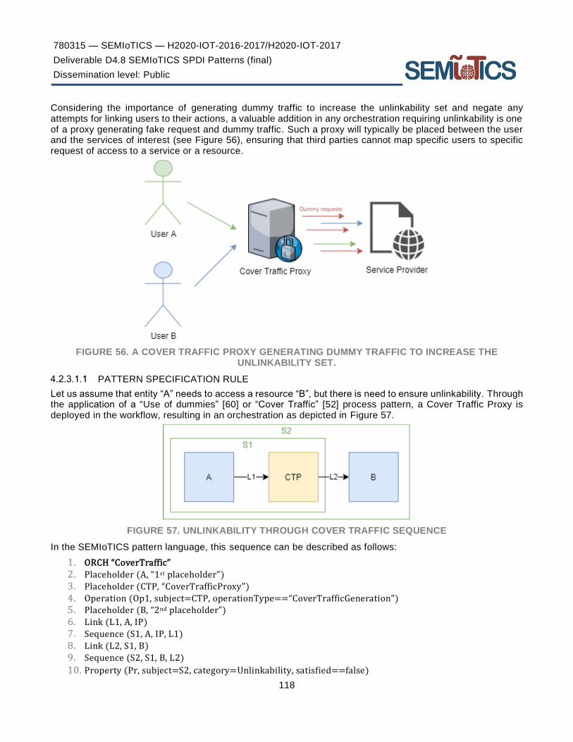
780315 — SEMIoTICS — H2020-IOT-2016-2017/H2020-IOT-2017
Deliverable D4.8 SEMIoTICS SPDI Patterns (final)
Dissemination level: Public
118
Considering the importance of generating dummy traffic to increase the unlinkability set and negate any attempts for linking users to their actions, a valuable addition in any orchestration requiring unlinkability is one of a proxy generating fake request and dummy traffic. Such a proxy will typically be placed between the user and the services of interest (see Figure 56), ensuring that third parties cannot map specific users to specific request of access to a service or a resource.
FIGURE 56. A COVER TRAFFIC PROXY GENERATING DUMMY TRAFFIC TO INCREASE THE UNLINKABILITY SET.
PATTERN SPECIFICATION RULE
Let us assume that entity “A” needs to access a resource “B”, but there is need to ensure unlinkability. Through the application of a “Use of dummies” [60] or “Cover Traffic” [52] process pattern, a Cover Traffic Proxy is deployed in the workflow, resulting in an orchestration as depicted in Figure 57.
FIGURE 57. UNLINKABILITY THROUGH COVER TRAFFIC SEQUENCE
In the SEMIoTICS pattern language, this sequence can be described as follows:
1. ORCH “CoverTraffic” 2. Placeholder (A, “1st placeholder”) 3. Placeholder (CTP, “CoverTrafficProxy”) 4. Operation (Op1, subject=CTP, operationType==“CoverTrafficGeneration”) 5. Placeholder (B, “2nd placeholder”) 6. Link (L1, A, IP) 7. Sequence (S1, A, IP, L1) 8. Link (L2, S1, B) 9. Sequence (S2, S1, B, L2)
10. Property (Pr, subject=S2, category=Unlinkability, satisfied==false)

780315 — SEMIoTICS — H2020-IOT-2016-2017/H2020-IOT-2017
Deliverable D4.8 SEMIoTICS SPDI Patterns (final)
Dissemination level: Public
119
Based on the above, the Identity Protector Pattern can be represented in Drools as shown in Table 36.
TABLE 36. COVER TRAFFIC AS DROOLS RULE
1. rule " Pseudonymisation - Sequence" 2. when
3. $P1: Placeholder($pl1:=placeholderid)
4. $P2: Placeholder($pl2:=placeholderid)
5. $PR1: Property($pl2:=subject, category=="Unlinkability", satisfied==true)
6. $P3: Placeholder($pl3:=placeholderid)
7.
8. $s1: Sequence($sid1:=id, $pID1:=placeholderA, $pID2:=placeholderB)
9. $s2: Sequence($sid2:=id, $sID1:=placeholderA, $pID3:=placeholderB)
10. 11. $PR2: Property($sID2:=subject, category=="Unlinkability", satisfied==false) 12. then 13. modify($PR2){satisfied=true}; 14. End
1. rule "" Unlinkability Verification with Certificate - Placeholder"
2. when
3. $P1: Placeholder($pID:=placeholderID)
4. $OP: Operation($opID:=operationID, $pID:=subject, operationType=="CoverTrafficGeneration")
5. $PR: Property ($pID:=subject, category=="Unlinkability", verificationType ==
"Certificate", $vermeans := means, satisfied==false)
6. then
7. if ($PR.checkCertificate($vermeans)) {
8. modify($PR){satisfied=true};
9. }
10. end
As we can see in the table above, there are two Drools rules for two different layers, sequence and placeholder. According to the first rule, the when part of the first rule specifies:
1. the three placeholders $P1, $P2 and $P3 of the pattern (lines 3-4 and 6); 2. the property “Unlinkability” that must hold for the second placeholder (line 5); 3. the order in which they should be executed (lines 8 and 9); 4. the orchestration property that can be guaranteed through the application of the pattern, i.e., the
unlinkability property in this case (line 11).
The then part verifies that the orchestration property ($PR) holds (satisfied=true), since all the necessary orchestration components (placeholders and properties) are present in the when part of the rule.
At the Placeholder level (second rule), we present an additional Drools Rule regarding the verification of the pattern. This second rule verifies that the Unlinkability property holds for an individual orchestration component. The way to verify that this property actually holds is utilizing a certificate from a trusted entity. The when part of the rule specifies:
1. the placeholder $P1 along with its operation “CoverTrafficGeneration” (lines 3-4); 2. the property that can be guaranteed utilizing the available certificate, i.e., the unlinkability property (line
5)
The then part calls the method that assesses the certificate and if the certificate is valid, the unlinkability property is verified (lines 7-8).
UNDETECTABILITY
Undetectability is “the inability for a third party to distinguish who is the user (among a set of potential users) using a service” [60]. A less user-focused and, thus, more general definition of undetectability is as follows: “Undetectability of an item of interest (IOI) from an attacker’s perspective means that the attacker cannot sufficiently distinguish whether it exists or not” [55].
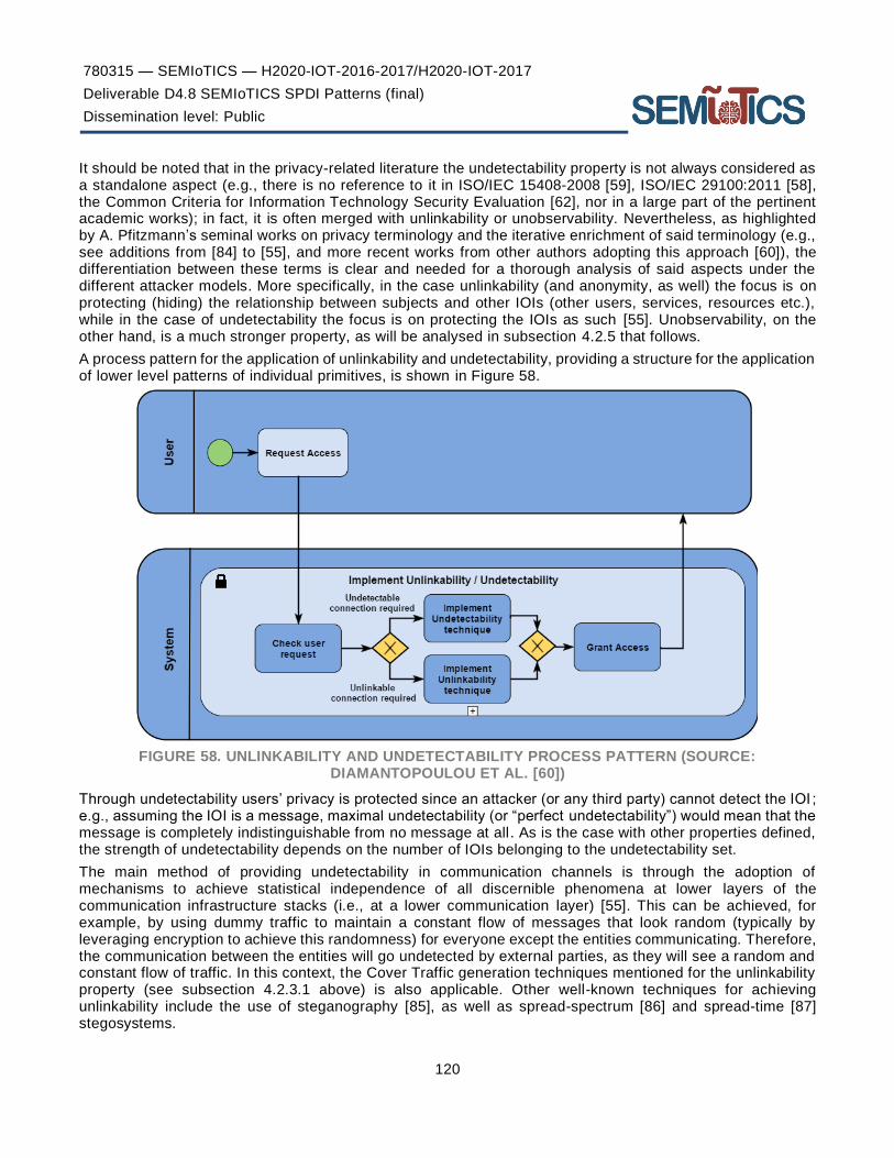
780315 — SEMIoTICS — H2020-IOT-2016-2017/H2020-IOT-2017
Deliverable D4.8 SEMIoTICS SPDI Patterns (final)
Dissemination level: Public
120
It should be noted that in the privacy-related literature the undetectability property is not always considered as a standalone aspect (e.g., there is no reference to it in ISO/IEC 15408-2008 [59], ISO/IEC 29100:2011 [58], the Common Criteria for Information Technology Security Evaluation [62], nor in a large part of the pertinent academic works); in fact, it is often merged with unlinkability or unobservability. Nevertheless, as highlighted by A. Pfitzmann’s seminal works on privacy terminology and the iterative enrichment of said terminology (e.g., see additions from [84] to [55], and more recent works from other authors adopting this approach [60]), the differentiation between these terms is clear and needed for a thorough analysis of said aspects under the different attacker models. More specifically, in the case unlinkability (and anonymity, as well) the focus is on protecting (hiding) the relationship between subjects and other IOIs (other users, services, resources etc.), while in the case of undetectability the focus is on protecting the IOIs as such [55]. Unobservability, on the other hand, is a much stronger property, as will be analysed in subsection 4.2.5 that follows.
A process pattern for the application of unlinkability and undetectability, providing a structure for the application of lower level patterns of individual primitives, is shown in Figure 58.
FIGURE 58. UNLINKABILITY AND UNDETECTABILITY PROCESS PATTERN (SOURCE: DIAMANTOPOULOU ET AL. [60])
Through undetectability users’ privacy is protected since an attacker (or any third party) cannot detect the IOI ; e.g., assuming the IOI is a message, maximal undetectability (or “perfect undetectability”) would mean that the message is completely indistinguishable from no message at all. As is the case with other properties defined, the strength of undetectability depends on the number of IOIs belonging to the undetectability set.
The main method of providing undetectability in communication channels is through the adoption of mechanisms to achieve statistical independence of all discernible phenomena at lower layers of the communication infrastructure stacks (i.e., at a lower communication layer) [55]. This can be achieved, for example, by using dummy traffic to maintain a constant flow of messages that look random (typically by leveraging encryption to achieve this randomness) for everyone except the entities communicating. Therefore, the communication between the entities will go undetected by external parties, as they will see a random and constant flow of traffic. In this context, the Cover Traffic generation techniques mentioned for the unlinkability property (see subsection 4.2.3.1 above) is also applicable. Other well-known techniques for achieving unlinkability include the use of steganography [85], as well as spread-spectrum [86] and spread-time [87] stegosystems.

780315 — SEMIoTICS — H2020-IOT-2016-2017/H2020-IOT-2017
Deliverable D4.8 SEMIoTICS SPDI Patterns (final)
Dissemination level: Public
121
STEGANOGRAPHY PATTERN DEFINITION
A key enabler of undetectability is the use of steganography, selecting the specific steganographic technique depending on the medium used for the communications. Steganography (from the Greek word “Στεγανογραφία”, translated to “covert writing”) focuses on techniques allowing the undetectable transmission of message by embedding them into innocuous carriers. These carriers are referred to as “stego-mediums” and they may include text messages, images & video, audio and others (e.g., using unused space in storage devices or the noise in communication channels). Depending on the stego-medium, different steganographic techniques can be employed (see Figure 59).
FIGURE 59. KEY STEGANOGRAPHIC TECHNIQUES DEPENDING ON TYPE OF STEGO-MEDIUM
So, in contrast to cryptography that is used to hide the contents of a message, steganography focuses on hiding the message itself. A high-level view of a steganographic system (“stegosystem”) is depicted in Figure 60, also covering the commonly occurring combination of steganography with encryption (for increased protection in case the covert message is exposed).

780315 — SEMIoTICS — H2020-IOT-2016-2017/H2020-IOT-2017
Deliverable D4.8 SEMIoTICS SPDI Patterns (final)
Dissemination level: Public
122
FIGURE 60. STEGANOGRAPHIC SYSTEM MODELS. SIMPLE (TOP) AND WITH ENCRYPTION (BOTTOM). (SOURCE: ZÖLLNER ET AL. [88])
PATTERN SPECIFICATION RULE
Let us assume that entity “A” needs to communicate with entity “B”, but there is need to ensure undetectability of the message being sent. For that purpose, steganography can be employed, resulting in a workflow as depicted in Figure 61.
FIGURE 61. UNDETECTABILTIY THROUGH STEGANOGRAPHY SEQUENCE
The sequence above can be described using the pattern language created in SEMIoTICS as depicted below:
1. ORCH “Steganography”
2. Placeholder (A, “1st placeholder”)
3. Placeholder (B, “2nd placeholder”)
4. Operation (Op1, subject=A, operationType==“StegoEmbed”)

780315 — SEMIoTICS — H2020-IOT-2016-2017/H2020-IOT-2017
Deliverable D4.8 SEMIoTICS SPDI Patterns (final)
Dissemination level: Public
123
5. Operation (Op2, subject=B, operationType==“StegoRetrieve”)
6. Link (L1, A, B) 7. Sequence (S1, A, B, L1)
8. Property (Pr, subject=S1, category=Undetectability, satisfied==false)
Based on the above, the Steganography pattern can be represented in Drools as shown in Table 37.
TABLE 37. STEGANOGRAPHY PATTERN AS DROOLS RULES
1. rule " Single Access Point Verification - Sequence" 2. when
3. $P1: Placeholder($pl1:=placeholderid)
4. $P2: Placeholder($pl2:=placeholderid)
5. $OP: Operation(($pl1:=subject, operationType=="StegoEmbed”)
6. $OP: Operation(($pl2:=subject, operationType=="StegoRetrieve”)
7. $ORCH: Sequence ($seq:=placeholderid, $pl1:=placeholdera, $pl2:=placeholderb)
8. $PR: Property ($seq:=subject, category=="Undetectability", satisfied==false)
9. then
10. modify($pr2){satisfied=true}; 11. End
1. rule "Undetectability Verification with Certificate #1 - Placeholder"
2. when
3. $P1: Placeholder($pl1:=placeholderid)
4. $Op: Operation($pl1:=subject, name=="StegoEmbed")
5. $PR: Property ($pl1:=subject, category == "Undetectability", verificationType ==
"Certificate", $vermeans := means, satisfied==false)
6. Then
7. if ($PR.checkCertificate($vermeans)) {
8. modify($PR){satisfied=true};
9. }
10. end
1. rule "Undetectability Verification with Certificate #2 - Placeholder"
2. when
3. $P1: Placeholder($pl1:=placeholderid)
4. $Op: Operation($pl1:=subject, name=="StegoRetrieve")
5. $PR: Property ($pl1:=subject, category == "Undetectability", verificationType ==
"Certificate", $vermeans := means, satisfied==false)
6. then
7. if ($PR.checkCertificate($vermeans)) {
8. modify($PR){satisfied=true};
9. }
10. end
As we can see in the table above, there are three Drools rules for two different layers, sequence and placeholder. According to the first rule, the when part of the first rule specifies:
1. the two placeholders $P1 and $P2 of the Steganography pattern (lines 3-4); 2. the operation types “StegoEmbed” and “StegoReceive” that must be supported by the 1 st and 2nd
placeholder respectively (lines 5 and 6); 3. the order in which they should be executed (line 7); 4. the orchestration property that can be guaranteed through the application of the pattern, i.e., the
Undetectability property in this case (line 8).
The then part verifies that the orchestration property ($PR) holds (satisfied=true), since all the necessary orchestration components (placeholders and properties) are present in the when part of the rule.

780315 — SEMIoTICS — H2020-IOT-2016-2017/H2020-IOT-2017
Deliverable D4.8 SEMIoTICS SPDI Patterns (final)
Dissemination level: Public
124
At the Placeholder level, second rule, we present two additional Drools Rules regarding the verification of the pattern. These rules verify that the “StegoEmbed” and “StegoReceive” operation types are present in the two placeholders as needed, which ensure that the Undetectability property holds for the individual orchestration components. In this example, the verification assumes the presence of a certificate from a trusted entity.
UNOBSERVABILITY
Unobservability “ensures that a user may use a resource or service without others, especially third parties, being
able to observe that the resource or service is being used” (ISO/IEC 15408-2008 [59]). Pfitzmann et al. [55] provide a definition that also shows the relationship (reliance) of unobservability to the co-existence of two other “weaker” properties defined above, undetectability and anonymity: “Unobservability of an item of interest
(IOI) means undetectability of the IOI against all subjects uninvolved in it and anonymity of the subject(s) involved in the IOI even against the other subject(s) involved in that IOI.”
A formal definition of unobservability is as follows (originally defined in [67], adapted in [61]):
An event E is unobservable for an attacker A, if for each observation B that A can make, the probability of E given B is greater zero and less one:
0 < 𝑃(𝐸 | 𝐵) < 1
A stricter requirement, which prevents that the value P(E | B) is too close to either 1 or 0, could be:
0 << 𝑃(𝐸 | 𝐵) << 1.
If for each possible observation B that A can make, the probability of an event E is equal to the probability of E given B, that is P(E) = P(E|B) then E is called perfectly unobservable.
As such, unobservability can be considered the strongest property of the ones previously defined and requires the provision of these underlying properties in order to be achieved. The unobservability process pattern is depicted in Figure 62, whereby the fact that unobservability implies the existence of anonymity or pseudonymity and undetectability is visualised. Here it should be clarified that, even though the terms of anonymity and pseudonymity are used interchangeably in the figure, as highlighted in [60], the pseudonymity in this context is only acceptable if a certain degree of unlinkability can be provided (e.g., through the use of transactions pseudonyms that offer a high degree of unlinkability).
FIGURE 62. UNOBSERVABILITY PROCESS PATTERN (SOURCE: DIAMANTOPOULOU ET AL. [60])

780315 — SEMIoTICS — H2020-IOT-2016-2017/H2020-IOT-2017
Deliverable D4.8 SEMIoTICS SPDI Patterns (final)
Dissemination level: Public
125
Furthermore, the strength of the unobservability depends on the strength of the anonymity/pseudonymity set and the strength of the undetectability set, i.e., the strength of the two underlying properties combined to achieve unobservability.
While the benefits of unobservability are significant (users can use a resource or service without others being able to observe that said use takes place, while having anonymity amongst all involved parties – an ideal condition from a privacy perspective), the complexity and overhead (strong cryptographic operations, complex calculations and significant traffic overhead typically involved) are significant, thus the usability is often questionable.
To implement unobservability, one must combine mechanisms offering anonymity with those providing unlinkability, as is also reflected in Figure 62. Any mechanism providing some type of anonymity (e.g. leveraging the Mix Network pattern defined in subsection 4.2.1.1), appropriately combined with dummy traffic (e.g., leveraging the Cover Traffic pattern provided in subsection 4.2.3.1), yields the corresponding type of unobservability [55]. Therefore, no unobservability-specific pattern will be defined herein.
Dependability
Dependability typically refers to the provision of expected service, towards task accomplishment in a reliable and trustworthy manner, and it entails reliability, safety, availability and security [89]. Nevertheless, the concept of security is covered separately above (see subsection 4.1), and in modern computer engineering, security is considered to encompass availability (along with confidentiality and integrity). Therefore, in the context of this work, Dependability properties will mainly focus on reliability, fault tolerance and safety aspects. These aspects, along with their relationship to the enabling patterns provided in this section are depicted in Figure 63.
FIGURE 63. DEPENDABILITY PROPERTIES AND ASSOCIATED PATTERNS

780315 — SEMIoTICS — H2020-IOT-2016-2017/H2020-IOT-2017
Deliverable D4.8 SEMIoTICS SPDI Patterns (final)
Dissemination level: Public
126
In order to guarantee end-to-end dependability properties, suitable component orchestrations on the different SEMIoTICS layers should be found in order to guarantee the required dependability property. If this does not exist, the substitution or the addition of current components with other atomic ones or orchestrations is required in order to guarantee dependability. This is also related to the components and the topology of the composition.
However, it should be noted that the composition of two components which preserve a dependability property does not necessarily guarantee that the composition will also preserve the same property. In addition, if a composition guarantees the conditions of a property, the atomic components may not preserve the property. As an example, let us consider a sequential (AND) composition of two components:
C → C1 ∧ C2
If a required property should be guaranteed by the C, the subcomponents C1 and C2 should satisfy the condition:
Property (C, Category) → Property (C1, Category) ∧ Property (C2, Category)
If there are no atomic components to guarantee the required property a recursive procedure is used in which successive (sub-) orchestrations are generated until the atomic components bound to them satisfy the required properties. The decomposition can be analysed as follows:
Property (C, Category) → Property (C1, Category) ∧ Property (C2, Category) →
(Property (C11, Category) ∧ Property (C12, Category))
∧ (Property (C21, Category) ∧ Property (C22, Category))
…until components C11, C12, C21, C22 that satisfy the required property Pro are found
On the other hand, the multi-choice (OR) composition of two components can be expressed as follows:
C → C1 ⋁ C2 → Property (C, Category) → Property (C1, Category) ⋁ Property (C2, Category)
The above procedures can be used to satisfy not only for dependability, but also for all the other SEMIoTICS property requirements.
Moreover, certain dependability properties will need to hold at the component level to enable the E2E properties to be achieved. One of the most important issues for a system designer is to validate system dependability of components as a critical condition for the design of complex network infrastructures and identify the weakest components in order to replace, redesign and find alternative solutions. System dependability properties such as reliability and availability depend on component’s arrangements. Stepwise decomposition can be used to recursively build network topologies using forward or de-orchestrations using backward chaining respectively, as depicted in Figure 64.
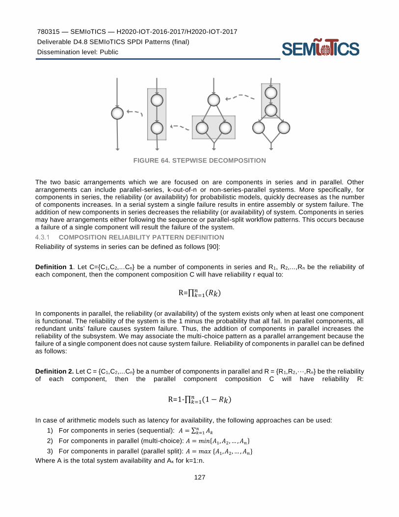
780315 — SEMIoTICS — H2020-IOT-2016-2017/H2020-IOT-2017
Deliverable D4.8 SEMIoTICS SPDI Patterns (final)
Dissemination level: Public
127
FIGURE 64. STEPWISE DECOMPOSITION
The two basic arrangements which we are focused on are components in series and in parallel. Other arrangements can include parallel-series, k-out-of-n or non-series-parallel systems. More specifically, for components in series, the reliability (or availability) for probabilistic models, quickly decreases as t he number of components increases. In a serial system a single failure results in entire assembly or system failure. The addition of new components in series decreases the reliability (or availability) of system. Components in series may have arrangements either following the sequence or parallel-split workflow patterns. This occurs because a failure of a single component will result the failure of the system.
COMPOSITION RELIABILITY PATTERN DEFINITION
Reliability of systems in series can be defined as follows [90]:
Definition 1. Let C={C1,C2,...Cn} be a number of components in series and R1, R2,...,Rn be the reliability of each component, then the component composition C will have reliability r equal to:
R=∏ (𝑅𝑘)𝑛𝑘=1
In components in parallel, the reliability (or availability) of the system exists only when at least one component is functional. The reliability of the system is the 1 minus the probability that all fail. In parallel components, all redundant units’ failure causes system failure. Thus, the addition of components in parallel increases the reliability of the subsystem. We may associate the multi-choice pattern as a parallel arrangement because the failure of a single component does not cause system failure. Reliability of components in parallel can be defined as follows:
Definition 2. Let C = {C1,C2,...Cn} be a number of components in parallel and R = {R1,R2,···,Rn} be the reliability of each component, then the parallel component composition C will have reliability R:
R=1-∏ (1 − 𝑅𝑘)𝑛𝑘=1
In case of arithmetic models such as latency for availability, the following approaches can be used:
1) For components in series (sequential): 𝐴 = ∑ 𝐴𝑘𝑛𝑘=1
2) For components in parallel (multi-choice): 𝐴 = 𝑚𝑖𝑛{𝐴1, 𝐴2, … , 𝐴𝑛}
3) For components in parallel (parallel split): 𝐴 = 𝑚𝑎𝑥 {𝐴1, 𝐴2, … , 𝐴𝑛}
Where A is the total system availability and Aκ for k=1:n.
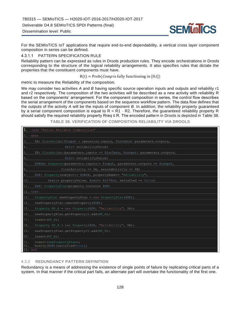
780315 — SEMIoTICS — H2020-IOT-2016-2017/H2020-IOT-2017
Deliverable D4.8 SEMIoTICS SPDI Patterns (final)
Dissemination level: Public
128
For the SEMIoTICS IoT applications that require end-to-end dependability, a vertical cross layer component composition in series can be defined.
PATTERN SPECIFICATION RULE
Reliability pattern can be expressed as rules in Drools production rules. They encode orchestrations in Drools corresponding to the structure of the logical reliability arrangements. It also specifies rules that dictate the properties that the constituent components must have.
R(t) = Prob(Comp is fully functioning in [0,t])
metric to measure the Reliability of the composition.
We may consider two activities A and B having specific source operation inputs and outputs and reliability r1 and r2 respectively. The composition of the two activities will be described as a new activity with reliability R based on the components’ arrangement. For the component composition in series, the control flow describes the serial arrangement of the components based on the sequence workflow pattern. The data flow defines that the outputs of the activity A will be the inputs of component B. In addition, the reliability property guaranteed by a serial component composition is equal to R = R1 · R2. Therefore, the guaranteed reliability property R should satisfy the required reliability property Rreq ≤ R. The encoded pattern in Drools is depicted in Table 38.
TABLE 38. VERIFICATION OF COMPOSITION RELIABILITY VIA DROOLS
1. rule "Serial Reliable Composition"
2. when
3. $A: Placeholder($input : operation.inputs, $intData: parameters.outputs,
4. $r1:= reliabilityValue)
5. $B: Placeholder(parameters.inputs == $intData, $output: parameters.outputs,
6. $r2:= reliabilityValue)
7. $ORCH: Sequence(parameters.inputs:= $input, parameters.outputs == $output,
8. firstActivity == $A, secondActivity == $B)
9. $OP: Property(subject:= $ORCH, propertyName== “Reliability",
10. $rel:= propertyValue, $rel<= $r1*$r2, satisfied == false)
11. $SP: PropertyPlan(property contains $OP)
12. then
13. PropertyPlan newPropertyPlan = new PropertyPlan($SP);
14. newPropertyPlan.removeProperty($OP);
15. Property NP_A = new Property($OP, "Reliability", $A);
16. newPropertyPlan.getProperty().add(NP_A);
17. insert(NP_A);
18. Property NP_B = new Property($OP, "Reliability", $B);
19. newPropertyPlan.getProperty().add(NP_B);
20. insert(NP_B);
21. insert(newPropertyPlan);
22. modify($OP){satisfied=true};
23. end
REDUNDANCY PATTERN DEFINITION
Redundancy is a means of addressing the existence of single points of failure by replicating critical parts of a system. In that manner if the critical part fails, an alternate part will overtake the functionality of the first one.

780315 — SEMIoTICS — H2020-IOT-2016-2017/H2020-IOT-2017
Deliverable D4.8 SEMIoTICS SPDI Patterns (final)
Dissemination level: Public
129
Hardware redundancy aims at having replicated set of hardware while software redundancy aims at having multiple instances of the software. If the replicated part is introduced in a stand-by form the active-passive redundancy is used, if it is introduced in active-active form the active-active redundancy is used (Figure 65).
FIGURE 65. TWO TYPES OF REDUNDANCY (SOURCE: RITTER ET AL. [33])
A known use of redundancy can be found in MySQL database cluster solution [46]. All single points of failure are made redundant, including data nodes, network cards, switches and links. Moreover, active-active redundancy is used at Apache’s Tomcat cluster solution for web-based applications. Apache web server connects to various Tomcat instances through mod_jk module before communicating with the database. If one of the Tomcat instances fails, the rest will continue to serve the incoming requests.
PATTERN SPECIFICATION RULE
Let us assume that we need to verify if the Redundancy property holds for the orchestration in Figure 66.
FIGURE 66. REDUNDANCY ORCHESTRATION
1. ORCH “Redundancy” 2. Placeholder (A, “1st placeholder”) 3. Placeholder (B1, “2nd placeholder 1st instance”)

780315 — SEMIoTICS — H2020-IOT-2016-2017/H2020-IOT-2017
Deliverable D4.8 SEMIoTICS SPDI Patterns (final)
Dissemination level: Public
130
4. Placeholder (B2, “2nd placeholder 2nd instance”) 5. Link (L1, A, B1) 6. Link (L1, A, B2) 7. Choice (Ch1, A, B1, B2, L1, L2)
8. Property (Pr, subject=Ch1, category=Redundancy, satisfied==false)
Based on the above, the Redundancy pattern can be represented in Drools as shown in Table 39.
The when part of the rule specifies:
1. the placeholders $p1, $p2 and $p3; 2. the extra condition that placeholder 2 and 3 are of the same type; 3. the order in which they should be executed ($ch), 4. the orchestration property that can be guaranteed through the application of the pattern, i .e., the
Redundancy property in this case ($pr).
The then part verifies that the orchestration property holds since every essential component is included in the when part (satisfied=true).
TABLE 39. REDUNDANCY PATTERN AS DROOLS RULES
rule "Redundancy Verification"
when
$p1: Placeholder($pID1:=placeholderID)
$p2: Placeholder($pID2:=placeholderID, $placeholerType1:=type)
$p3: Placeholder($pID3:=placeholderID, $placeholerType2:=type,
$placeholerType1==$placeholerType2)
$ch: Choice($chID:=id, $ pID1:=placeholderA, $pID2:=placeholderB, $pID3:=placeholderC) $pr: Property($chID:=subject, category=="Redundancy", satisfied==false)
then
modify($pr2){satisfied=true};
end
FAULT MANAGEMENT PATTERN DEFINITION
Fault Management is a set of mechanisms to detect failures so that recovery can be done and system be notified about recovered parts so as to gain redundancy in the system [39]. These mechanisms include
1. Monitoring of the system components (single point of failure). Monitoring can be implemented as ACKNOLEDGEMENT messages, I AM ALIVE / ARE YOU ALIVE messages, or as a WATCHDOG mechanism.
2. Failure notification from the system part that failed. 3. Failure Recovery in the manner of self-recovery or manual intervention. 4. Recovery notification from the system part that has just recovered in order to start synchronization
with its peers and get ready for the incoming requests.
PATTERN SPECIFICATION RULE
Let us assume that we need to verify if the FaultManagement property holds for the sequence in Figure 67.

780315 — SEMIoTICS — H2020-IOT-2016-2017/H2020-IOT-2017
Deliverable D4.8 SEMIoTICS SPDI Patterns (final)
Dissemination level: Public
131
FIGURE 67. FAULT MANAGEMENT SEQUENCE
The sequence above can be described using the pattern language created in SEMIoTICS as depicted below:
1. ORCH “Fault Management”
2. Placeholder (A, “1st placeholder”)
3. Placeholder (B, “2nd placeholder”)
4. Link (L1, A, B)
5. Sequence (S1, A, B, L1)
6. Property (Pr, subject=S1, category= FaultManagement, satisfied==false)
Based on the above, the Fault Management Pattern can be represented in Drools as shown in Table 40.
TABLE 40. FAULT MANAGEMENT AS DROOLS RULE
1. rule " Fault Management - Sequence" 2. when
3. $P1: Placeholder($pl1:=placeholderid)
4. $P2: Placeholder($pl2:=placeholderid)
5. $ORCH: Sequence ($seq:=placeholderid, $pl1:=placeholdera, $pl2:=placeholderb)
6. $PR: Property ($seq:=subject, category=="FaultManagement", satisfied==false)
7. then
8. insert(new Property($P1, "FaultManagement", false));
9. insert(new Property($P2, "FaultManagement", false));
10. End
1. rule " Fault Management Verification with Certificate - Link" 2. when
3. $P: Placeholder($Id:=placeholderID)
4. $PR: Property ($Id:=subject, category == "FaultManagement", verificationType == "Certifica
te", $vermeans := means, satisfied==false)
5. then
6. if ($PR.checkCertificate($vermeans)) {
7. modify($PR){satisfied=true};
8. }
9. end
The when part of the first rule specifies:
1. the two placeholders $P1 and $P2 (lines 3-4); 2. the order in which they should be executed (line 5), 3. the orchestration property that can be guaranteed through the application of the pattern, i.e., the
FaultManagement property in this case (line 6).

780315 — SEMIoTICS — H2020-IOT-2016-2017/H2020-IOT-2017
Deliverable D4.8 SEMIoTICS SPDI Patterns (final)
Dissemination level: Public
132
The then part generates the security properties that, if satisfied by the activity placeholders of the pattern’s orchestration, would make the orchestration to satisfy the orchestration property. Each of the placeholders should satisfy the FaultManagement property (lines 8-9).
The second Rule is a verification rule and verifies that the FaultManagement property holds for an individual orchestration component (Placeholder). In this case, in order to verify that this property holds, we utilize a certificate from a trusted entity.
The when part of the rule specifies:
1. the placeholder $P1 (lines 3); 2. the property that can be guaranteed utilizing the available certificate, i.e., the FaultManagement
property in this case (line 4)
The then part calls the method that assesses the certificate and if the certificate is valid, the FaultManagement property is verified (lines 6-7).
Interoperability
As discussed in Section 2.4, four levels of interoperability are considered in SEMIoTICS: technological, syntactic, semantic and organizational interoperability. An approach towards a pattern rule definition for these cases is detailed in the subsections that follow. A more holistic presentation of interoperability-related aspects, especially in the context of the network layer, are presented in deliverable D3.10 (“Network-level Semantic Interoperability (final)”), which also includes the full set of interoperability patterns of SEMIoTICS.
In more detail, from bottom up, the following types of interoperability can be distinguished and will be covered by SEMIoTICS [47]:
• Technical interoperability – enables seamless operation and cooperation of heterogeneous devices that utilize different communication protocols on the transmission layer
• Syntactic interoperability – establishes clearly defined formats for data, interfaces and encoding
• Semantic interoperability – settles commonly agreed information models and ontologies for the used terms that are processed by the interfaces or are included in exchanged data
• Organizational interoperability – cross-domain and cross-platform service integration and orchestration, through common semantic and programming interfaces
It is important to note that the higher levels of interoperability assume the existence of the lower ones, otherwise they cannot be achieved, e.g., to have syntactic interoperability, you need to have established technical first (see Figure 68).

780315 — SEMIoTICS — H2020-IOT-2016-2017/H2020-IOT-2017
Deliverable D4.8 SEMIoTICS SPDI Patterns (final)
Dissemination level: Public
133
FIGURE 68. DIFFERENT LEVELS OF INTEROPERABILITY AND THEIR DEPENDENCY RELATIONSHIPS
Moreover, even though the boundaries of each level are not strict, we consider in our methodology that technical, syntactic, and semantic interoperability enable E2E interoperability between the involved technologies within a platform and/or specific IoT deployment, while operation across verticals and platforms is accomplished through organizational interoperability.
Regarding data states, it should be noted that interoperability cannot be defined for data at rest since, by definition, data as rest is data that is not being used, access or processed upon and, thus , no interoperability challenges arise. When an entity accesses said data (to read a value, perform analytics etc.), it becomes data in transit and in processing, depending on the scenario. Therefore, the Interoperability of data at rest is not covered within the defined patterns.
The interoperability properties, and their relationships with the associated patterns defined herein are visualised in Figure 69, while the definition of the interoperability patterns of SEMIoTICS is detailed in the subsections that follow.

780315 — SEMIoTICS — H2020-IOT-2016-2017/H2020-IOT-2017
Deliverable D4.8 SEMIoTICS SPDI Patterns (final)
Dissemination level: Public
134
FIGURE 69. INTEROPERABILITY PROPERTIES AND ASSOCIATED PATTERNS
TECHNICAL INTEROPERABILITY
Technical Interoperability is about enabling the communication between systems and platforms at a protocol level and the infrastructure needed for those protocols to operate [91]. Within the context of the work presented herein, the associated pattern rule aims to cover and address the technological issues that may arise from the interaction among heterogeneous devices, with different technical specifications and supported communication means on the transmission layer (e.g., wireless motes communicating via ZigBee, other motes via 802.15.4, and more powerful infrastructure devices communicating over WiFi or Ethernet), as is often the case in IoT environments.
TECHNICAL MEDIATOR PATTERN DEFINITION
One way to achieve Technical Interoperability is through the deployment of a Technical Mediator, which connects to components with various technical attributes. An example of such a component is a sensor gateway that acts as a bridge between 802.15.4 radio and wired network infrastructures (e.g., using 6LBR [92]).
Let us consider:
– C := the set of all instantiated components
– TA := A set of technical attributes
– C1, C2 ⊆ C, where C1 ≠ C2
– Ci_TA ⊆ TA := technical attributes of Ci
– TMD := Technical Mediator
Then, we can define the following:
Lemma 1: If C1, C2 are at the same domain and C1_TA ∩ C2_TA ≠ ⌀ then C1 and C2 are directly technically
interoperable.
Lemma 2: If C1, C2 are on different domain but are both directly technically interoperable with TMD (Figure 70)
then C1, C2 are indirectly technically interoperable.

780315 — SEMIoTICS — H2020-IOT-2016-2017/H2020-IOT-2017
Deliverable D4.8 SEMIoTICS SPDI Patterns (final)
Dissemination level: Public
135
Lemma 3: If C1, C2 are directly or indirectly technical interoperable, then C1, C2 are technically interoperable.
FIGURE 70. INDIRECT TECHNICAL INTEROPERABILITY VIA TECHNICAL MEDIATOR
PATTERN SPECIFICATION RULE
Using the above detailed pattern, we can derive the following workflow-based definition of technical interoperability for the fundamental scenario of two IoT components communicating with each other:
1. WF “technical-interoperability”
2. Placeholder (A1, (PlaceholderActivity, PlaceholderDescription))
3. Placeholder (A2, (PlaceholderActivity, PlaceholderDescription))
4. Placeholder (TMD, (PlaceholderActivity, ”technical mediator”))
5. Link (L1, A1, A2)
6. Link (L2, A1, TMD)
7. Link (L3, A2, TMD)
8. Property (conn1, L1, required, (pattern-based, pattern),” technical-interoperability”, in_transit)
9. Property (conn2, L2, required, (pattern-based, pattern),” technical-interoperability”, in_transit)
10. Property (conn3, L3, required, (pattern-based, pattern),” technical-interoperability”, in_transit)
11. Property (conn4, “_technical-interoperability”, required, (pattern-based, PR1), ”_technical-interoperability”, end_to_end)
12. Pattern rule: (PR1: conn1 || (conn2, conn3) ➔ conn4)
For details on this workflow-based approach followed in SEMIoTICS pattern definition, please refer to deliverable D4.1, and its follow-up D4.8. In said deliverables the process of transforming these workflows and

780315 — SEMIoTICS — H2020-IOT-2016-2017/H2020-IOT-2017
Deliverable D4.8 SEMIoTICS SPDI Patterns (final)
Dissemination level: Public
136
the pertinent requirements into a machine-processable format using Drools rules and facts is also documented. The output of this process is shown in Table 41.
TABLE 41. TECHNICAL INTEROPERABILITY VERIFICATION DROOL RULE
rule "Sequence Technical Interoperability Verification" when Placeholder($pA:=placeholderid) Property ($pA:=subject, category=="technical", $prvaluein1:=input_value,
$prvalueout1:=output_value, satisfied==true) Placeholder($pB:=placeholderid) Property ($pB:=subject, category=="technical", $prvaluein2:=input_value,
$prvalueout2:=out_value, satisfied==true) Sequence($sId:=placeholderid, $pA:=placeholdera, $pB:=placeholderb) $PR: Property ($sId:=subject, category=="technical", $prvalueout1==$prvaluein2,
satisfied==false) then modify($PR){satisfied=true, input_value=$prvaluein1, output_value=$prvalueout2}; end
Whenever the “Sequence Technical Interoperability Verification” rule, is fired, the Property with category technical of a Sequence is verified. According to the LSH part of the rule, if:
i) the two Placeholders of a Sequence have a Property of category technical; and
ii) the output_value of the first Placeholder is equal to the input_value of the second Placeholder ($prvalueout1==$prvaluein2),
then the RHS part of the rule verifies the corresponding Property of the Sequence in question and sets its input_value and output_value to $prvalueout1 and $prvaluein2 respectively.
A property of category technical with input_value $prvaluein1 and output_value $prvaluout1, denotes that the corresponding component uses a specific input communication protocol whose description is given by $prvaluein1 and a specific output communication protocol whose description is given by $prvalueout1. For example, if we have a component (PlaceholderA) which has an endpoint that uses the Wi-Fi 802.11a protocol, then this would be translated to a Property with category technical and input_value “Wi-Fi 802.11a”. Additionally, if the said component uses a different protocol for forwarding information to other components such as Ethernet 802.3, then the output_value of the same Property will be “Ethernet 802.3”.
Figure 71 depicts a sequence (Sequence1) of two Placeholders. PlaceholderA has a property of category technical with input_value “Wi-Fi 802.11a” and output_value “Ethernet 802.3”. Similarly, PlaceholderB has a property of category technical with input_value “Ethernet 802.3” and output_value “Wi-Fi 802.11g”. As step 1 shows, the corresponding property of the Sequence1 is false and input_value and output_value are not set. The aforementioned protocol properties trigger the “Sequence Technical Interoperability Verification” rule, verifying (satisfied=true) the property of category technical of Sequence1, and assigning the appropriate values to input_value and output_value of the property (step 2).

780315 — SEMIoTICS — H2020-IOT-2016-2017/H2020-IOT-2017
Deliverable D4.8 SEMIoTICS SPDI Patterns (final)
Dissemination level: Public
137
FIGURE 71. EXECUTION STEPS OF TECHNICAL INTEROPERABILITY PATTERN
SYNTACTIC INTEROPERABILITY
Syntactic Interoperability refers to the challenge of enabling interactions between different devices which may often be communicating using different messaging protocols, while also usually associated with data formats [91]. This is especially challenging in the IoT domain where, while manufacturers typically try to adopt standardised messaging protocols, the plethora of such established protocols with different intr insic characteristics (e.g., RESTful HTTP, CoAP, XMP, MQTT, DPWS) and a variety of data formats (e.g., XML, JSON), which leads to a fragmented landscape.
SYNTACTIC MEDIATOR PATTERN DEFINITION
A means of achieving Syntactic Interoperability is through the deployment of a Syntactic Mediator, i.e. a component which connects to components with various protocols and translates between them. An example of such a component is SeMIBIoT [93], a secure multi-protocol integration bridge acting as a gateway and providing hop-by-hop or end-to-end secure communications between an array of heterogeneous nodes and standardized IoT protocols.
Let us consider:
– C := the set of all instantiated ingredients/activities in an IoT orchestration
– PR := A set of protocols
– C1,C2 ⊆ C, where C1 ≠ C2
– Ci_PR ⊆ PR := protocols supported by Ci
– SyMD := Syntactic Mediator
Then, we can define the following:

780315 — SEMIoTICS — H2020-IOT-2016-2017/H2020-IOT-2017
Deliverable D4.8 SEMIoTICS SPDI Patterns (final)
Dissemination level: Public
138
Lemma 4: If C1, C2 are technically interoperable and C1_PR ∩ C2_PR ≠ ⌀ then C1 and C2 are directly syntactically
interoperable.
Lemma 5: If C1, C2 are technically interoperable and are both directly syntactical interoperable with SyMD (Figure
72) then C1, C2 are indirectly syntactically interoperable
Lemma 6: If C1, C2 are directly or indirectly syntactically interoperable, then C1, C2 are syntactically interoperable.
FIGURE 72. INDIRECT SYNTACTIC INTEROPERABILITY VIA SYNTACTIC MEDIATOR
PATTERN SPECIFICATION RULE
Considering the above, we can define the following workflow-based definition for Syntactic Interoperability between two IoT activities A1, A2 interacting with each other.
1. WF “syntactic-interoperability”
2. Placeholder (A1, (PlaceholderActivity, PlaceholderDescription))
3. Placeholder (A2, (PlaceholderActivity, PlaceholderDescription))
4. Placeholder (SyMD, (PlaceholderActivity,”syntactic mediator”))
5. Link (L1, A1, A2)
6. Link (L2, A1, SyMD)
7. Link (L3, A2, SyMD)
8. Property (conn01, L1, required, (pattern-based, pattern),” technical-interoperability”, in_transit)
9. Property (conn02, L2, required, (pattern-based, pattern),” technical-interoperability”, in_transit)
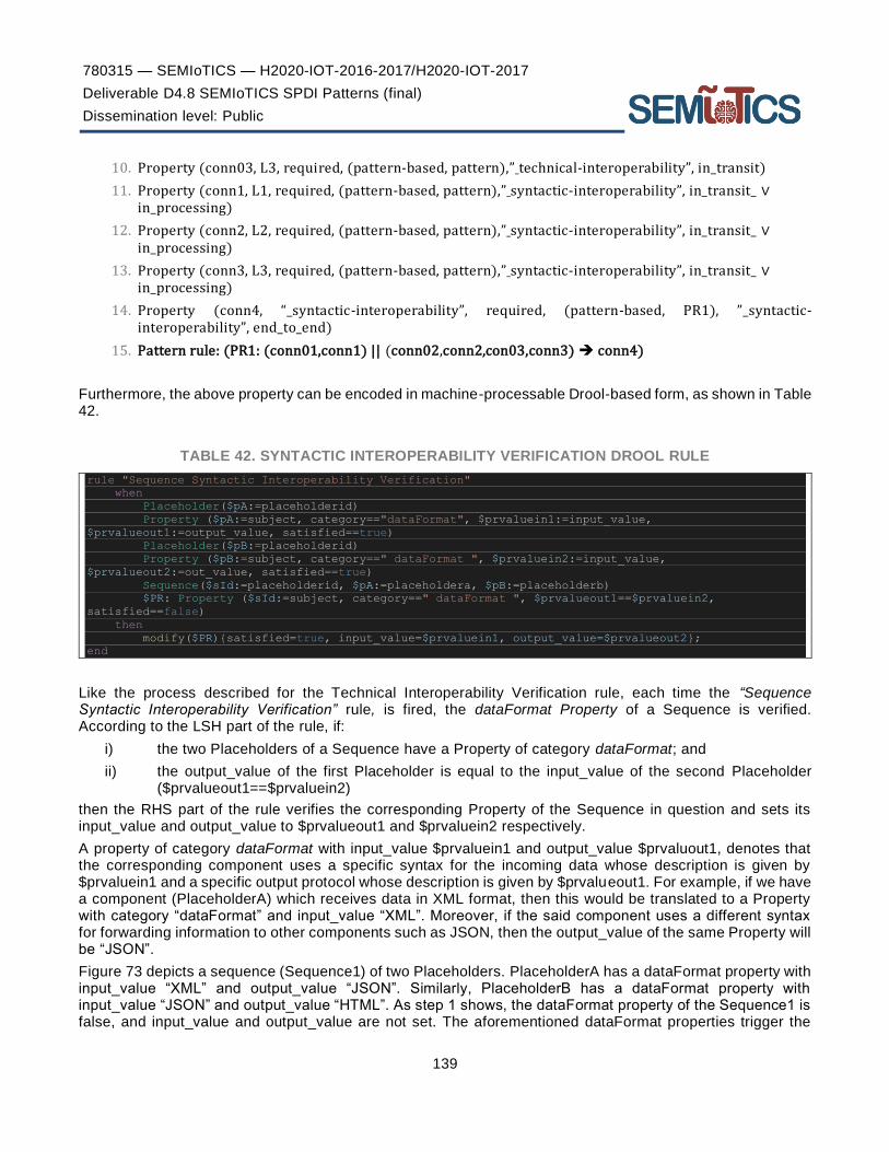
780315 — SEMIoTICS — H2020-IOT-2016-2017/H2020-IOT-2017
Deliverable D4.8 SEMIoTICS SPDI Patterns (final)
Dissemination level: Public
139
10. Property (conn03, L3, required, (pattern-based, pattern),” technical-interoperability”, in_transit)
11. Property (conn1, L1, required, (pattern-based, pattern),” syntactic-interoperability”, in_transit_ ∨ in_processing)
12. Property (conn2, L2, required, (pattern-based, pattern),” syntactic-interoperability”, in_transit_ ∨ in_processing)
13. Property (conn3, L3, required, (pattern-based, pattern),” syntactic-interoperability”, in_transit_ ∨ in_processing)
14. Property (conn4, “_syntactic-interoperability”, required, (pattern-based, PR1), ”_syntactic-interoperability”, end_to_end)
15. Pattern rule: (PR1: (conn01,conn1) || (conn02,conn2,con03,conn3) ➔ conn4)
Furthermore, the above property can be encoded in machine-processable Drool-based form, as shown in Table 42.
TABLE 42. SYNTACTIC INTEROPERABILITY VERIFICATION DROOL RULE
rule "Sequence Syntactic Interoperability Verification" when Placeholder($pA:=placeholderid) Property ($pA:=subject, category=="dataFormat", $prvaluein1:=input_value,
$prvalueout1:=output_value, satisfied==true) Placeholder($pB:=placeholderid) Property ($pB:=subject, category==" dataFormat ", $prvaluein2:=input_value,
$prvalueout2:=out_value, satisfied==true) Sequence($sId:=placeholderid, $pA:=placeholdera, $pB:=placeholderb) $PR: Property ($sId:=subject, category==" dataFormat ", $prvalueout1==$prvaluein2,
satisfied==false) then modify($PR){satisfied=true, input_value=$prvaluein1, output_value=$prvalueout2}; end
Like the process described for the Technical Interoperability Verification rule, each time the “Sequence Syntactic Interoperability Verification” rule, is fired, the dataFormat Property of a Sequence is verified. According to the LSH part of the rule, if:
i) the two Placeholders of a Sequence have a Property of category dataFormat; and
ii) the output_value of the first Placeholder is equal to the input_value of the second Placeholder ($prvalueout1==$prvaluein2)
then the RHS part of the rule verifies the corresponding Property of the Sequence in question and sets its input_value and output_value to $prvalueout1 and $prvaluein2 respectively.
A property of category dataFormat with input_value $prvaluein1 and output_value $prvaluout1, denotes that the corresponding component uses a specific syntax for the incoming data whose description is given by $prvaluein1 and a specific output protocol whose description is given by $prvalueout1. For example, if we have a component (PlaceholderA) which receives data in XML format, then this would be translated to a Property with category “dataFormat” and input_value “XML”. Moreover, if the said component uses a different syntax for forwarding information to other components such as JSON, then the output_value of the same Property will be “JSON”.
Figure 73 depicts a sequence (Sequence1) of two Placeholders. PlaceholderA has a dataFormat property with input_value “XML” and output_value “JSON”. Similarly, PlaceholderB has a dataFormat property with input_value “JSON” and output_value “HTML”. As step 1 shows, the dataFormat property of the Sequence1 is false, and input_value and output_value are not set. The aforementioned dataFormat properties trigger the

780315 — SEMIoTICS — H2020-IOT-2016-2017/H2020-IOT-2017
Deliverable D4.8 SEMIoTICS SPDI Patterns (final)
Dissemination level: Public
140
“Sequence Syntactic Interoperability Verification” rule, verifying(satisfied=true) the dataFormat property of Sequence1 and assigning the appropriate values to input_value and output_value of the property (step 2).
FIGURE 73. EXECUTION STEPS OF SYNTACTIC INTEROPERABILITY PATTERN
SEMANTIC INTEROPERABILITY
Interoperability on the Semantic level means that there is a common understanding between the involved systems of the meaning of the content (information) being exchanged. This means that the exchanged data have an unambiguous, shared meaning. For example, temperature units can be Fahrenheit, Celsius or Kelvin, but they express the same information which can be obtained after proper instance transformation.
SEMANTIC MEDIATOR PATTERN DEFINITION
Semantic Interoperability can be achieved at the implementation level through the deployment of a Semantic Mediator component; e.g. the Semantic Mediator as defined in Hatzivasilis et al [94], or a Semantic Information Broker [95].
Let us consider:
– C := the set of all instantiated components
– MDL := A set of semantic models
– C1,C2 ⊆ C , where C1 ≠ C2
– Ci_MDL ⊆ MDL := semantic models used by Ci
– SeMD := Semantic Mediator
Then, we can define the following:

780315 — SEMIoTICS — H2020-IOT-2016-2017/H2020-IOT-2017
Deliverable D4.8 SEMIoTICS SPDI Patterns (final)
Dissemination level: Public
141
Lemma 7: If C1, C2 are syntactically interoperable and C1_MDL ∩ C2_MDL ≠ ⌀ then C1 and C2 are directly semantically
interoperable
Lemma 8: If C1, C2 are syntactically interoperable and are both directly semantically interoperable with SeMD
(Figure 74), then C1, C2 are indirectly semantically interoperable
Lemma 9: If C1, C2 are directly or indirectly semantically interoperable, then C1, C2 are semantically interoperable.
FIGURE 74. INDIRECT SEMANTIC INTEROPERABILITY VIA SEMANTIC MEDIATOR
PATTERN SPECIFICATION RULE
Based on the above, the workflow-based definition of semantic interoperability in the fundamental scenario of two IoT activities A1 and A2 interacting with each other, is as follows:
1. WF “semantic-interoperability”
2. Placeholder (A1, (PlaceholderActivity, PlaceholderDescription))
3. Placeholder (A2, (PlaceholderActivity, PlaceholderDescription))
4. Placeholder (SeMD, (PlaceholderActivity,”Semantic Broker”))
5. Link (L1, A1, A2)
6. Link (L2, A1, SeMD)
7. Link (L3, A2, SeMD)
8. Property (conn01, L1, required, (pattern-based, pattern),” syntactic-interoperability” , in_transit_ ∨ in_processing)

780315 — SEMIoTICS — H2020-IOT-2016-2017/H2020-IOT-2017
Deliverable D4.8 SEMIoTICS SPDI Patterns (final)
Dissemination level: Public
142
9. Property (conn02, L2, required, (pattern-based, pattern),” syntactic-interoperability” , in_transit_ ∨ in_processing)
10. Property (conn03, L3, required, (pattern-based, pattern),” syntactic-interoperability” , in_transit_ ∨ in_processing)
11. Property (conn1, L1, required, (pattern-based, pattern),” semantic-interoperability” , in_processing)
12. Property (conn2, L2, required, (pattern-based, pattern),” semantic -interoperability” , in_processing)
13. Property (conn3, L3, required, (pattern-based, pattern),” semantic -interoperability” , in_processing)
14. Property (conn4, “_semantic-interoperability”, required, (pattern-based, PR1),” “_semantic-interoperability”, end_to_end)
15. Pattern rule: (PR1: (conn01,conn1) || (conn02,conn2,conn03,conn3) ➔ conn4)
Moreover, we can define the semantic interoperability rule in a machine-processable Drool rule format, as show in Table 43.
TABLE 43. SEMANTIC INTEROPERABILITY VERIFICATION DROOL RULE
rule "Sequence Semantic Interoperability Verification" when Placeholder($pA:=placeholderid) Property ($pA:=subject, category=="semantic", $prvaluein1:=input_value,
$prvalueout1:=output_value, satisfied==true) Placeholder($pB:=placeholderid) Property ($pB:=subject, category=="semantic", $prvaluein2:=input_value,
$prvalueout2:=out_value, satisfied==true) Sequence($sId:=placeholderid, $pA:=placeholdera, $pB:=placeholderb) $PR: Property ($sId:=subject, category=="semantic", $prvalueout1==$prvaluein2,
satisfied==false) then modify($PR){satisfied=true, input_value=$prvaluein1, output_value=$prvalueout2}; end
The “Sequence Semantic Interoperability Verification” rule verifies the semantic Property of a Sequence every time it is triggered. According to the LSH part of the rule, if:
i) the two Placeholders of a Sequence have a Property of category semantic, and
ii) the output_value of the first Placeholder is equal to the input_value of the second Placeholder ($prvalueout1==$prvaluein2),
then the RHS part of the rule verifies the corresponding Property of the Sequence in question and sets its input_value and output_value to $prvalueout1 and $prvaluein2 respectively.
A property of category semantic with input_value $prvaluein1 and output_value $prvaluout1, denotes that the corresponding component has a specific understanding regarding the content of the incoming data whose description is given by $prvaluein1 and a specific understanding regarding the content of the output data whose description is given by $prvalueout1. For example, if we have a component (PlaceholderA) which understands temperature in Kelvin scale, then this would be translated to a Property with category “semantic” and input_value “Kelvin”. Moreover, if the said component uses a different understanding for forwarding temperature to other components such as Celsius, then the output_value of the same Property will be “Celsius”.
Figure 75 depicts a sequence (Sequence1) of two Placeholders. PlaceholderA has a semantic property with input_value “Kelvin” and output_value “Celsius”. Similarly, PlaceholderB has a semantic property w ith input_value “Celsius” and output_value “Fahrenheit”. As step 1 shows, the semantic property of the Sequence1 is false and input_value and output_value are not set. The aforementioned semantic properties trigger the
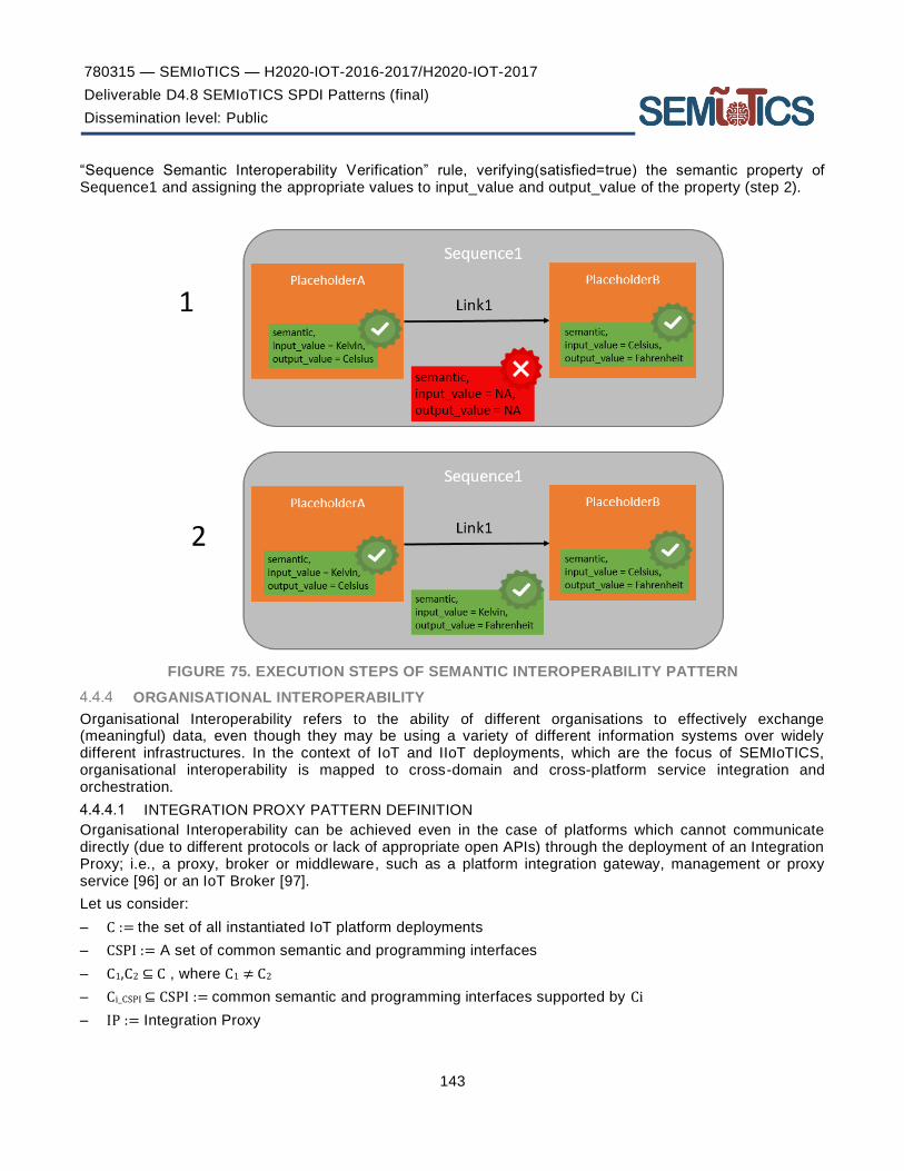
780315 — SEMIoTICS — H2020-IOT-2016-2017/H2020-IOT-2017
Deliverable D4.8 SEMIoTICS SPDI Patterns (final)
Dissemination level: Public
143
“Sequence Semantic Interoperability Verification” rule, verifying(satisfied=true) the semantic property of Sequence1 and assigning the appropriate values to input_value and output_value of the property (step 2).
FIGURE 75. EXECUTION STEPS OF SEMANTIC INTEROPERABILITY PATTERN
ORGANISATIONAL INTEROPERABILITY
Organisational Interoperability refers to the ability of different organisations to effectively exchange (meaningful) data, even though they may be using a variety of different information systems over widely different infrastructures. In the context of IoT and IIoT deployments, which are the focus of SEMIoTICS, organisational interoperability is mapped to cross-domain and cross-platform service integration and orchestration.
INTEGRATION PROXY PATTERN DEFINITION
Organisational Interoperability can be achieved even in the case of platforms which cannot communicate directly (due to different protocols or lack of appropriate open APIs) through the deployment of an Integration Proxy; i.e., a proxy, broker or middleware, such as a platform integration gateway, management or proxy service [96] or an IoT Broker [97].
Let us consider:
– C := the set of all instantiated IoT platform deployments
– CSPI := A set of common semantic and programming interfaces
– C1,C2 ⊆ C , where C1 ≠ C2
– Ci_CSPI ⊆ CSPI := common semantic and programming interfaces supported by Ci
– IP := Integration Proxy

780315 — SEMIoTICS — H2020-IOT-2016-2017/H2020-IOT-2017
Deliverable D4.8 SEMIoTICS SPDI Patterns (final)
Dissemination level: Public
144
Then, we can define the following:
Lemma 10: If C1, C2 are semantically interoperable and C1_CSPI ∩ C2_CSPI ≠ ⌀ then C1 and C2 are directly
organisationally interoperable
Lemma 11: If C1, C2 are semantically interoperable and are both directly organisationally interoperable with IP
(Figure 76), then C1, C2 are indirectly organisationally interoperable
Lemma 12: If C1, C2 are directly or indirectly organisationally interoperable, then C1, C2 are organisationally
interoperable.
FIGURE 76. INDIRECT ORGANISATIONAL INTEROPERABILITY VIA INTEGRATION PROXY
PATTERN SPECIFICATION RULE
Based on the above, we can derive the following workflow-based definition of organisational interoperability for the fundamental case of two IoT platform deployments, A1 & A2, interacting with each other:
1. WF “organisational-interoperability”
2. Placeholder (A1, (PlaceholderActivity, PlaceholderDescription))
3. Placeholder (A2, (PlaceholderActivity, PlaceholderDescription))
4. Placeholder (IP, (PlaceholderActivity,”Integration Proxy”))
5. Link (L1, A1, A2)
6. Link (L2, A1, IP)
7. Link (L3, A2, IP)
8. Property (conn01, L1, required, (pattern-based, pattern),” semantic -interoperability” , in_processing)
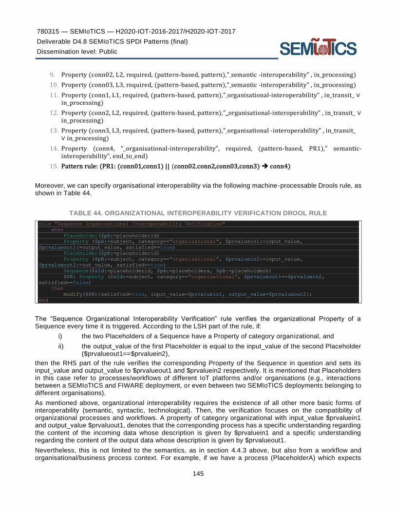
780315 — SEMIoTICS — H2020-IOT-2016-2017/H2020-IOT-2017
Deliverable D4.8 SEMIoTICS SPDI Patterns (final)
Dissemination level: Public
145
9. Property (conn02, L2, required, (pattern-based, pattern),” semantic -interoperability” , in_processing)
10. Property (conn03, L3, required, (pattern-based, pattern),” semantic -interoperability” , in_processing)
11. Property (conn1, L1, required, (pattern-based, pattern),” organisational-interoperability” , in_transit_ ∨ in_processing)
12. Property (conn2, L2, required, (pattern-based, pattern),”_organisational-interoperability” , in_transit_ ∨ in_processing)
13. Property (conn3, L3, required, (pattern-based, pattern),” organisational -interoperability” , in_transit_ ∨ in_processing)
14. Property (conn4, “_organisational-interoperability”, required, (pattern-based, PR1),” semantic-interoperability”, end_to_end)
15. Pattern rule: (PR1: (conn01,conn1) || (conn02,conn2,conn03,conn3) ➔ conn4)
Moreover, we can specify organisational interoperability via the following machine-processable Drools rule, as shown in Table 44.
TABLE 44. ORGANIZATIONAL INTEROPERABILITY VERIFICATION DROOL RULE
rule "Sequence Organizational Interoperability Verification" when Placeholder($pA:=placeholderid) Property ($pA:=subject, category=="organizational", $prvaluein1:=input_value,
$prvalueout1:=output_value, satisfied==true) Placeholder($pB:=placeholderid) Property ($pB:=subject, category=="organizational", $prvaluein2:=input_value,
$prvalueout2:=out_value, satisfied==true) Sequence($sId:=placeholderid, $pA:=placeholdera, $pB:=placeholderb) $PR: Property ($sId:=subject, category=="organizational", $prvalueout1==$prvaluein2,
satisfied==false) then modify($PR){satisfied=true, input_value=$prvaluein1, output_value=$prvalueout2}; end
The “Sequence Organizational Interoperability Verification” rule verifies the organizational Property of a Sequence every time it is triggered. According to the LSH part of the rule, if:
i) the two Placeholders of a Sequence have a Property of category organizational, and
ii) the output_value of the first Placeholder is equal to the input_value of the second Placeholder ($prvalueout1==$prvaluein2),
then the RHS part of the rule verifies the corresponding Property of the Sequence in question and sets its input_value and output_value to $prvalueout1 and $prvaluein2 respectively. It is mentioned that Placeholders in this case refer to processes/workflows of different IoT platforms and/or organisations (e.g., interactions between a SEMIoTICS and FIWARE deployment, or even between two SEMIoTICS deployments belonging to different organisations).
As mentioned above, organizational interoperability requires the existence of all other more basic forms of interoperability (semantic, syntactic, technological). Then, the ver ification focuses on the compatibility of organizational processes and workflows. A property of category organizational with input_value $prvaluein1 and output_value $prvaluout1, denotes that the corresponding process has a specific understanding regarding the content of the incoming data whose description is given by $prvaluein1 and a specific understanding regarding the content of the output data whose description is given by $prvalueout1.
Nevertheless, this is not limited to the semantics, as in section 4.4.3 above, but also from a workflow and organisational/business process context. For example, if we have a process (PlaceholderA) which expects

780315 — SEMIoTICS — H2020-IOT-2016-2017/H2020-IOT-2017
Deliverable D4.8 SEMIoTICS SPDI Patterns (final)
Dissemination level: Public
146
inputs from a specific organisational activity (e.g., new IoT asset registration request), then this would be translated to a Property with category “organizational” and input_value “Activity”. Moreover, if this process uses different means for its output (e.g., needs to interact with an external service residing in another organisation/IoT platform to retrieve assets available there), then the output_value of the same Property will be “ExtService”.
To visualise this, Figure 77 depicts a sequence (Sequence1) of two Placeholders. PlaceholderA, residing in “IoT Platform A” has an organizational property with input_value “Activity” and output_value “ExtService”. Similarly, PlaceholderB has an organizational property with input_value “ServiceReq” (to denote that process PlaceholderB residing in IoT Platform B expects requests from external parties) and output_value “Workflow” (to denote this external request is then mapped to an internal workflow; e.g., for local asset discover). As step 1 shows, the organizational property of the Sequence1 is false, and input_value and output_value are not set. The aforementioned organizational properties trigger the “Sequence Organizational Interoperability Verification” rule, verifying (“satisfied=true”) the organizational property of Sequence1 and assigning the appropriate values to input_value and output_value of the property (step 2).
FIGURE 77. EXECUTION STEPS OF ORGANISATIONAL INTEROPERABILITY PATTERN
E2E INTEROPERABILITY
Until now, we have described how the individual interoperability types (i.e., Technical, Syntactic, Semantic and Organisational) are defined and verified for the fundamental case of a sequence of two components/activities. Nevertheless, using these rules the E2E properties of these simple as well as more complex orchestrations can be verified. More specifically, using the process defined in the previous sections (i.e., leveraging the
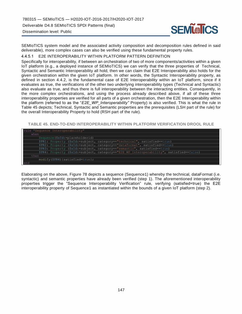
780315 — SEMIoTICS — H2020-IOT-2016-2017/H2020-IOT-2017
Deliverable D4.8 SEMIoTICS SPDI Patterns (final)
Dissemination level: Public
147
SEMIoTICS system model and the associated activity composition and decomposition rules defined in said deliverable), more complex cases can also be verified using these fundamental property rules.
E2E INTEROPERABILITY WITHIN PLATFORM PATTERN DEFINITION
Specifically for interoperability, if between an orchestration of two of more components/activities within a given IoT platform (e.g., a deployed instance of SEMIoTICS) we can verify that the three properties of Technical, Syntactic and Semantic Interoperability all hold, then we can claim that E2E Interoperability also holds for the given orchestration within the given IoT platform. In other words, the Syntactic Interoperability property, as defined in section 4.4.2, is the fundamental case of E2E Interoperability within an IoT platform, since if it evaluates as true, the verifications of the other two underlying interoperability types (Technical and Syntactic) also evaluate as true, and thus there is full interoperability between the interacting entities. Consequently, in the more complex orchestrations, and using the process already described above, if all of these three interoperability properties are verified for all parts of a given orchestration, then the E2E Interoperability within the platform (referred to as the “E2E_WP_Interoperability” Property) is also verified. This is what the rule in Table 45 depicts; Technical, Syntactic and Semantic properties are the prerequisites (LSH part of the rule) for the overall Interoperability Property to hold (RSH part of the rule).
TABLE 45. END-TO-END INTEROPERABILITY WITHIN PLATFORM VERIFICATION DROOL RULE
rule "Sequence Interoperability" when Sequence($sId:=placeholderid) $PR1: Property ($sId:=subject, category=="technical", satisfied==true) $PR2: Property ($sId:=subject, category=="dataFormat", satisfied==true) $PR3: Property ($sId:=subject, category=="semantic", satisfied==true) $PR4: Property ($sId:=subject, category=="E2E_WP_Interoperability", satisfied==false) then modify($PR4){satisfied=true}; end
Elaborating on the above, Figure 78 depicts a sequence (Sequence1) whereby the technical, dataFormat (i.e. syntactic) and semantic properties have already been verified (step 1). The aforementioned interoperability properties trigger the “Sequence Interoperability Verification” rule, verifying (satisfied=true) the E2E interoperability property of Sequence1 as instantiated within the bounds of a given IoT platform (step 2).
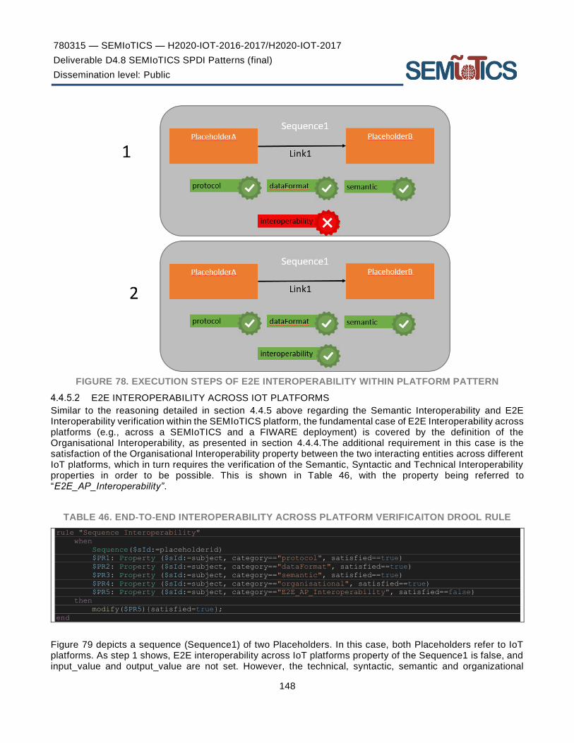
780315 — SEMIoTICS — H2020-IOT-2016-2017/H2020-IOT-2017
Deliverable D4.8 SEMIoTICS SPDI Patterns (final)
Dissemination level: Public
148
FIGURE 78. EXECUTION STEPS OF E2E INTEROPERABILITY WITHIN PLATFORM PATTERN
E2E INTEROPERABILITY ACROSS IOT PLATFORMS
Similar to the reasoning detailed in section 4.4.5 above regarding the Semantic Interoperability and E2E Interoperability verification within the SEMIoTICS platform, the fundamental case of E2E Interoperability across platforms (e.g., across a SEMIoTICS and a FIWARE deployment) is covered by the definition of the Organisational Interoperability, as presented in section 4.4.4.The additional requirement in this case is the satisfaction of the Organisational Interoperability property between the two interacting entities across different IoT platforms, which in turn requires the verification of the Semantic, Syntactic and Technical Interoperability properties in order to be possible. This is shown in Table 46, with the property being referred to “E2E_AP_Interoperability”.
TABLE 46. END-TO-END INTEROPERABILITY ACROSS PLATFORM VERIFICAITON DROOL RULE
rule "Sequence Interoperability" when Sequence($sId:=placeholderid) $PR1: Property ($sId:=subject, category=="protocol", satisfied==true) $PR2: Property ($sId:=subject, category=="dataFormat", satisfied==true) $PR3: Property ($sId:=subject, category=="semantic", satisfied==true)
$PR4: Property ($sId:=subject, category=="organisational", satisfied==true) $PR5: Property ($sId:=subject, category=="E2E_AP_Interoperability", satisfied==false) then modify($PR5){satisfied=true}; end
Figure 79 depicts a sequence (Sequence1) of two Placeholders. In this case, both Placeholders refer to IoT platforms. As step 1 shows, E2E interoperability across IoT platforms property of the Sequence1 is false, and input_value and output_value are not set. However, the technical, syntactic, semantic and organizational

780315 — SEMIoTICS — H2020-IOT-2016-2017/H2020-IOT-2017
Deliverable D4.8 SEMIoTICS SPDI Patterns (final)
Dissemination level: Public
149
properties hold for Sequence1. The aforementioned properties trigger the “Sequence Interoperability Across IoT Platforms” rule, verifying(satisfied=true) the semantic property of Sequence1 (step 2).
FIGURE 79. EXECUTION STEPS OF E2E INTEROPERABILITY ACROSS PLATFORMS PATTERN
Considering more complex orchestrations, in the context of potential SEMIoTICS applications, and as detailed in section 2.4, end-to-end interoperability should cover heterogeneous cases of cross-platform and scale connectivity. More specifically, based on previous work [98] carried out in the BIG IoT project, the cases of interoperability across IoT platforms, as sketched in Figure 80, include:
- Cross platform – applications or services access resources from multiple platforms though common interfaces.
- Platform-scale independence – integrates the resources from platforms at different scale in the way that application can uniformly aggregate information for different scale platforms (cloud-, fog-, device-level).
- Platform independence – refers to distinct platforms that implement the same functionality in the way that ensures that a single driver application can interoperate with both platforms in a uniform manner without requiring any changes.
- Cross application domain – refers to uniform access to information from platforms that process data from different domains.
- Higher-level service facades – services can also interact themselves through common API. Therefore, a single application can interact with two platforms to create value-added operations.

780315 — SEMIoTICS — H2020-IOT-2016-2017/H2020-IOT-2017
Deliverable D4.8 SEMIoTICS SPDI Patterns (final)
Dissemination level: Public
150
FIGURE 80. FIVE CASES OF INTEROPERABILITY ACROSS PLATFORMS [98]
Each of the five cases described above and depicted in Figure 80 is supported through the SEMIoTICS end-to-end semantic interoperability mechanisms and the network mechanisms detailed herein.
More specifically, and as mentioned in the case of the Interoperability with platforms (section 4.4.5), all of these cases can be covered by the fundamental E2E_AP_Interoperability property verification rule definition, through decomposition of said complex scenarios to one or more verifications of instances of these fundamental property.

780315 — SEMIoTICS — H2020-IOT-2016-2017/H2020-IOT-2017
Deliverable D4.8 SEMIoTICS SPDI Patterns (final)
Dissemination level: Public
151
QoS Patterns
Other than the aspects of availability and dependability (and associated concepts, e.g. fault tolerance) that are already integral in the SPDI properties, other QoS-related parameters (e.g. latency) can also be accommodated by the pattern language adopted.
To achieve this, the pattern language and the associated components deployed at all layers of the SEMIoTICS deployment are able to leverage appropriate monitors and interface with the necessary mechanisms to act as an enabler for configuring the network and triggering network updates / reconfigurations, as needed (e.g. for fault tolerance or QoS). As can be seen in subsections 3.3 (Language Model) and 3.4 (Language Constructs), Java class Property owns an attribute Category, allowing Pattern Engines to monitor QoS properties of the components of an IoT service orchestration. Moreover, the properties associated with the Link class directly affect the requirements relayed to the network layer (with the associated properties reasoned by the Pattern Engine embedded at the SDN controller; see subsection 3.7.2.2).
Leveraging the above, a number of QoS-related patterns can be defined, to extend the properties encompassed in the SEMIoTICS pattern-driven approach. A characteristic example of network bandwidth is defined in the subsection that follows, while similarly additional patterns can be defined for other QoS properties (packet loss, latency, etc.).
QOS BANDWIDTH PATTERN DEFINITION
Bandwidth is measured as the amount of data that can be transferred from point A to point B within a network in a specific amount of time. Typically, bandwidth is expressed as a bitrate and measured in bits per second (bps).
Qosbandwidth pattern is used to verify that the corresponding property holds for an orchestration. The Qosbandwidth property has an attribute Value, where is stored the bandwidth measurement of the property subject (placeholder or link).
PATTERN SPECIFICATION RULE
Let us assume that we need to verify if the Qosbandwidth property holds for the sequence in Figure 81.
FIGURE 81: QOS BANDWIDTH SEQUENCE
The sequence above can be described using the pattern language created in SEMIoTICS as depicted below:
1. ORCH “QoSbandwidth”
2. Placeholder (A, “1st placeholder”)
3. Placeholder (B, “2nd placeholder”)
4. Link (L1, A, B)
5. Sequence (S1, A, B, L1)
6. Property (Pr, subject=S1, category= Qosbandwidth, satisfied==false)
Based on the above, the Qosbandwidth Pattern can be represented in Drools as shown in Table 47. We present 2 rules. According to the first rule, the when part of the first rule specifies:
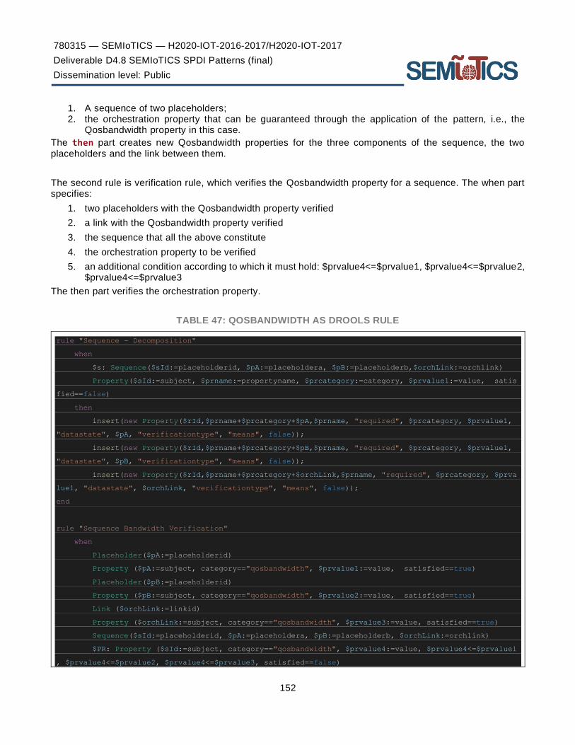
780315 — SEMIoTICS — H2020-IOT-2016-2017/H2020-IOT-2017
Deliverable D4.8 SEMIoTICS SPDI Patterns (final)
Dissemination level: Public
152
1. A sequence of two placeholders; 2. the orchestration property that can be guaranteed through the application of the pattern, i.e., the
Qosbandwidth property in this case.
The then part creates new Qosbandwidth properties for the three components of the sequence, the two placeholders and the link between them.
The second rule is verification rule, which verifies the Qosbandwidth property for a sequence. The when part specifies:
1. two placeholders with the Qosbandwidth property verified
2. a link with the Qosbandwidth property verified
3. the sequence that all the above constitute
4. the orchestration property to be verified
5. an additional condition according to which it must hold: $prvalue4<=$prvalue1, $prvalue4<=$prvalue2, $prvalue4<=$prvalue3
The then part verifies the orchestration property.
TABLE 47: QOSBANDWIDTH AS DROOLS RULE
rule "Sequence - Decomposition"
when
$s: Sequence($sId:=placeholderid, $pA:=placeholdera, $pB:=placeholderb,$orchLink:=orchlink)
Property($sId:=subject, $prname:=propertyname, $prcategory:=category, $prvalue1:=value, satis
fied==false)
then
insert(new Property($rId,$prname+$prcategory+$pA,$prname, "required", $prcategory, $prvalue1,
"datastate", $pA, "verificationtype", "means", false));
insert(new Property($rId,$prname+$prcategory+$pB,$prname, "required", $prcategory, $prvalue1,
"datastate", $pB, "verificationtype", "means", false));
insert(new Property($rId,$prname+$prcategory+$orchLink,$prname, "required", $prcategory, $prva
lue1, "datastate", $orchLink, "verificationtype", "means", false));
end
rule "Sequence Bandwidth Verification"
when
Placeholder($pA:=placeholderid)
Property ($pA:=subject, category=="qosbandwidth", $prvalue1:=value, satisfied==true)
Placeholder($pB:=placeholderid)
Property ($pB:=subject, category=="qosbandwidth", $prvalue2:=value, satisfied==true)
Link ($orchLink:=linkid)
Property ($orchLink:=subject, category=="qosbandwidth", $prvalue3:=value, satisfied==true)
Sequence($sId:=placeholderid, $pA:=placeholdera, $pB:=placeholderb, $orchLink:=orchlink)
$PR: Property ($sId:=subject, category=="qosbandwidth", $prvalue4:=value, $prvalue4<=$prvalue1
, $prvalue4<=$prvalue2, $prvalue4<=$prvalue3, satisfied==false)

780315 — SEMIoTICS — H2020-IOT-2016-2017/H2020-IOT-2017
Deliverable D4.8 SEMIoTICS SPDI Patterns (final)
Dissemination level: Public
153
then
modify($PR){satisfied=true};
end
Overview of SEMIoTICS patterns
Aggregating the patterns presented in this deliverable, Table 48 presents the coverage that the SEMIoTICS patterns offer in terms of the considered properties, data states and platform connectivity cases.
TABLE 48. SUMMARY OF SEMIOTICS PATTERNS AND THEIR COVERAGE
Pattern
Property Data State Coverage Platform
Connectivity
Concept or Pattern
Source S P D I QoS
In
Transit
At
Rest
In
Processing Within Across
# Name
1 Overall Security N/A (known
concept)
2 Overall Confidentiality Ritter et al. [33]
3 Encrypted Storage Kienzle et al. [35]
4 Encrypted Channels Schumacher et al.
[36]
5 Encrypted Processing Ahituv et al.[37]
6 Perfect Security Property
(PSP)
Zakinthinos et al.
[48]
7 Overall Integrity Ritter et al. [33]
8 Safe Storage Ritter et al. [33]

780315 — SEMIoTICS — H2020-IOT-2016-2017/H2020-IOT-2017
Deliverable D4.8 SEMIoTICS SPDI Patterns (final)
Dissemination level: Public
154
9 Safe Channel Ritter et al. [33]
10 Safe Processing Ritter et al. [33]
11 Hash Check N/A (known
concept)
12 Server Sandbox Kienzle et al. [35]
13 Minefield Kienzle et al. [35]
14 Overall Availability Avizienis et al. [50]
15 Uptime N/A (known
concept)
16 Non-repudiation/Auditability
/Accountability Ritter et al. [33]
17 Signed Message Ritter et al. [33]
18 Audit Log Kienzle et al. [35]
19 Overall Authorisation Schumacher et al.
[36]
20 Single Access Schumacher et al.
[36]

780315 — SEMIoTICS — H2020-IOT-2016-2017/H2020-IOT-2017
Deliverable D4.8 SEMIoTICS SPDI Patterns (final)
Dissemination level: Public
155
21 Authorisation Enforcer Schumacher et al.
[36]
22 Overall Authentication Schumacher et al.
[36]
23 Authentication Enforcer Schumacher et al.
[36]
24 Authenticated Channel Durand et al. [44]
25 Account Lockout Kienzle et al. [35]
26 Authenticated Session Kienzle et al. [35]
27 Blacklist Kienzle et al. [35]
28 Overall Privacy Pfitzmann et al. [55]
29 Mix Network M. Hafiz [51] &
S. Fischer-Hübner
[61]
30 Orchestration Identifiability N/A (known
concept)
31 Pseudonymity Diamantopoulou et
al. [55]
32 Identity Protector S. Fischer-Hübner
[61]

780315 — SEMIoTICS — H2020-IOT-2016-2017/H2020-IOT-2017
Deliverable D4.8 SEMIoTICS SPDI Patterns (final)
Dissemination level: Public
156
33 Unlinkability S. Fischer-Hübner
[61]
34 Cover Traffic M. Hafiz [52]
35 Undetectability Diamantopoulou et
al. [55]
36 Steganography
Zöllner et al. [88]
& S. Fischer-
Hübner [61]
37 Unobservability
Pfitzmann et al. [55]
& Diamantopoulou
et al. [55]
39 Dependability Laprie et al [89]
40 Composition Reliability Petroulakis et al.
[90]
41 Redundancy Ritter et al. [33]
42 Fault Management Ahluwalia et al. [39]
43 Technical Interoperability Hatzivasilis et al.
[47]
44 Syntactic Interoperability Hatzivasilis et al.
[47]
45 Semantic Interoperability Hatzivasilis et al.
[47]

780315 — SEMIoTICS — H2020-IOT-2016-2017/H2020-IOT-2017
Deliverable D4.8 SEMIoTICS SPDI Patterns (final)
Dissemination level: Public
157
46 Organizational
Interoperability
Hatzivasilis et al.
[47]
47 E2E Interoperability Within N/A (documented in
D3.10)
48 E2E Interoperability Across N/A (documented in
D3.10)
49 qosBandwidth N/A (known
concept)
As can be seen from the above table, the SEMIoTICS patterns (49 in total) offer a complete coverage of all SPDI properties and their sub-properties, also covering all data states and all cases of platform connectivity. Nevertheless, and as mentioned in the introductory comments of this section, this work does not intend to provide a survey and aggregate all such patterns from the literature and other resources.
The characteristic examples provided herein and adapted to the SEMIoTICS language and approach are adequate for the scenarios studied in the context of the SEMIoTICS use cases. Still, it is expected that for a real-world deployment of SEMIoTICS in other scenarios and vertical domains, the above will need to be enriched with additional patterns that may be more appropriate for the intricacies of the specific environment.
There are various sources of such patterns that could be used for identifying new ones to enrich the SEMIoTICS set of patterns provided here. Nowadays there is a plethora of security patterns provided by the security community, included in many books, catalogues and the academic literature.
We could indicatively mention: Steel et al. [41], who present 23 security patterns for J2EE applications, Web services and identity management; the security pattern book led by M. Schumacher [36] including 46 patterns divided in sections such as enterprise security and risk management, identification and authentication, access control, accounting, firewall architecture, and secure internet application; iii) the Security Patterns Repository Version 1.0 [35] consisting of 26 patterns and 3 mini-patterns, and focusing on the domain of web application security; iv) a book published by Microsoft’s Patterns and Practices group [101] that included 18 security-related patterns.
Furthermore, a recent literature study on privacy patterns research [99] identified 148 privacy patterns in total, recognising that privacy patterns are a relatively young field compared to others. Some more recent works continue to expand the available privacy patterns (e.g., the work of Gabel et al. [100] on pseudonymity patterns). Other indicative resources for the retrieval of privacy-related patterns include works from: Chung et al. [102], M. Hafiz [49][52], O. Drozd [103], T. Schümmer [53], M. Schumacher [54], C. Graf et al. [104].
Furthermore, a number of online repositories can be found focusing on the provision of patterns, such as those from Arcticura14 encompassing various ICT aspects including security, and privacy specific repositories151617.
14 https://patterns.arcitura.com/ 15 https://privacypatterns.eu 16 https://privacypatterns.org/ 17 http://privacypatterns.wu.ac.at:8080/catalog/

780315 — SEMIoTICS — H2020-IOT-2016-2017/H2020-IOT-2017
Deliverable D4.8 SEMIoTICS SPDI Patterns (final)
Dissemination level: Public
158
Regarding adding new patterns, following the update of the model, if needed (see subsection 3.9 on model and language versioning), patterns can be described using the SEMIoTICS language (and associated EBNF grammar), and their correctness is checked by the ANLTR4 lexer/parser before their translation into Drools rules. Patterns are then maintained across multiple rule files, while the same interface that is used for the insertion of new recipes is used for the insertion of these new patterns as well. In that way we can easily manage a large number of rules. A pattern Drools rule must be maintained for as long as the corresponding pattern is meant to be used. If a pattern is considered deprecated, the rule must be removed.

780315 — SEMIoTICS — H2020-IOT-2016-2017/H2020-IOT-2017
Deliverable D4.8 SEMIoTICS SPDI Patterns (final)
Dissemination level: Public
159
5 IOT SERVICE ORCHESTRATION The materialization of the Internet of Things is done nowadays by various IoT platforms, offering devices and services (IoT offerings). This is a world where applications are distributed and realized by the interoperations among services, in order to become more capable and powerful. The next logical step towards the facilitation of the usage of IoT offerings is their composition. As a result, we need a language to express how composing parts of IoT applications are put together in a workflow. Our choice is the IoT Recipe model (see D3.4, Section 3.3.2), which allows the aggregation of IoT offerings based on semantic composition rules. The t ool-kit that accompanies the Recipe model includes a lightweight graphical tool that eases the creation of Recipes as composition of offerings. What follows is the instantiation of the Recipe and the automatic production of executable application code.
Regarding the description of a workflow in details, the IoT Recipe model is quite expressive. Its core structure shares many characteristics with BPMN 2.0, the global standard for business processes. First of all, the Task of BPMN corresponds to the Ingredient of the Recipe model. A Task is an atomic Activity, a work that cannot be broken down to a finer level of detail. An Ingredient corresponds to data or a function offered by a provider. Then, in BPMN we have the concept of Sub-process that can be opened up to show its internal details. This is also offered by Recipe model since a Recipe is an offering. That means that Sub-recipes are supported. Moreover, Recipe Patterns correspond to BPMN Gateways. Gateways are responsible for the control of the Process flow and are separated in different types (Exclusive, Inclusive, Parallel, Event -Based). Recipe Patterns are also Ingredients and are used for the expression of the conditions under which Ingredients connect. The list of the Recipe Patterns types includes If-Then, If-Then-Else, Sequence, Conjunction, Disjunction, Negation, Iterate, Repeat-until, Repeat-while, Split, Unordered list, Choice and Split-Join. Finally, in BPMN there is the concept of Event, something that happens during the Process and affects the flow. Events make event-driven processes possible. The concept of Event was not present in the first version of Recipe model. However, an extension allowed the support of for asynchronous, event-based offerings composition. A detailed presentation of the aforementioned model is available in Section 5.1 below.
Although the Recipe model is capable of describing IoT workflows, extensions are necessary to achieve application orchestrations that guarantee SPDI properties. First, we need to be able to describe Links of the network level. The attributes of a Link are described in Section 3.3. Furthermore, Ingredients must be extended to include information about their SPDI properties. Only QoS constraints are offered at the moment . Finally, monitoring capabilities should be added to Ingredients that will provide the evidence for the presence of the SPDI and QoS properties.
Recipe-driven IoT Application Workflow definition
In this section, we present an extension of the IoT Recipe model (D3.4, Section 3.3.2), which allows the description of IoT application workflows. We add the ability to specify QoS requirements within the model. This can be utilized by user interfaces for IoT application developers to enable the expression of QoS requirements in a simplified manner at the application layer. We aim to translate these user defined QoS requirements then into concrete SPDI patterns that define a specific SDN/NFV configuration. Using the recipe model here has the advantage of facilitating the IoT application development and will make IoT applications more reliable as networking QoS constraints can be integrated more easily.

780315 — SEMIoTICS — H2020-IOT-2016-2017/H2020-IOT-2017
Deliverable D4.8 SEMIoTICS SPDI Patterns (final)
Dissemination level: Public
160
FIGURE 82. THE RECIPE MODEL
In previous work [30], [98] we have presented a model to define abstract IoT orchestrations as recipes. In this model, shown in Figure 82, a recipe is a template for a workflow of interactions between multiple ingredients, i.e., devices or services. When a recipe is instantiated, ingredients are replaced with concrete things, described with their own respective Thing Description. A draft for a user interface (UI) for the specification of recipes can be seen in Figure 83. Besides the workflow of the recipe, QoS constraints and SPDI patterns can be defined on the interactions.
The user of this tool would be typically an IoT application developer. This user wants to focus on the logic of the application flow. Specifically, the user does not have to have expertise in configuring the network and physical connections between the involved IoT devices. The benefit of the recipe approach is that these configurations are automatically done by the tool and the underlying technologies.
In the example, the UI has been used to define a recipe that combines multiple services of devices within a wind turbine (microphone, accelerometer and anemometer) with the purpose of sending out alarms in case of severe conditions (i.e., detected noise, motion and winds) are above a threshold. The abstract service composition and associated constraints are first defined in the UI. The composition and graph are then translated to concrete configurations.

780315 — SEMIoTICS — H2020-IOT-2016-2017/H2020-IOT-2017
Deliverable D4.8 SEMIoTICS SPDI Patterns (final)
Dissemination level: Public
161
FIGURE 83. EXAMPLE USER INTERFACE TO DEFINE RECIPES
In Figure 84, the sequence of creating and instantiating a recipe is depicted. First, the recipe creation phase takes place. This is independent of the later instantiation phase and can also be done by a different user.
1. At startup, the Recipe Cooker tool requests the capabilities of all available things on the network from the Thing Directory on the backend. These capabilities are reported back to the Recipe Cooker in the Thing Description format. Besides the syntax and semantics of inputs and outputs, the Thing Description defines general capabilities (e.g., resolution of a camera).
2. Next, the user defines the recipe (i.e., the application flow including if/else and for-loops) and specifies the expected capabilities (selected from the downloaded thing capabilities) of ingredients, such as input and output data types. The user utilizes the Recipe Cooker tool for this specification.
Second, the recipe instantiation phase takes place. This phase can be conducted by a different user and could potentially happen at a much later point in time.
1. The user starts by selecting a recipe that reflects as a template the workflow he/she wants to implement in his site. Therefore, the Recipe Cooker requests all semantically matching things (for the ingredients of the selected recipe) from the Thing Directory. The computational complexity of this matching process (simple subsumption reasoning) was tested in our previous work [30]. It scales well enough, on a machine with 8GB RAM and 2.4 GHz i5 intel processor, it results in a computation time of one second being broken at about 650 recipes. The system scales quadratically in the number of recipes, but with low constant factors. Thereby, the closed world assumption is held here: the knowledge base is known to be complete, since the Thing Directory is held up-to-date by design of our multi-layer architecture.
2. Next, the user can select a concrete thing for each ingredient. This manual step, conducted by the user (application developer), ensures the proper selection of suitable activities in the application composition. The activities in this composition are the matching and selected things ret rieved from the Thing Directory. They are described using the Thing Description (TD) model and format defined by the W3C Thing Description specification.
3. Then, the user triggers the deployment of the recipe instance. Therefore, the recipe instance is transmitted to the Pattern Orchestrator in the format of a so-called Recipe Runtime Configuration (RRC). The RRC is then translated into:
a. network pattern (i.e., configurations of the SDN controller as Drools rules)
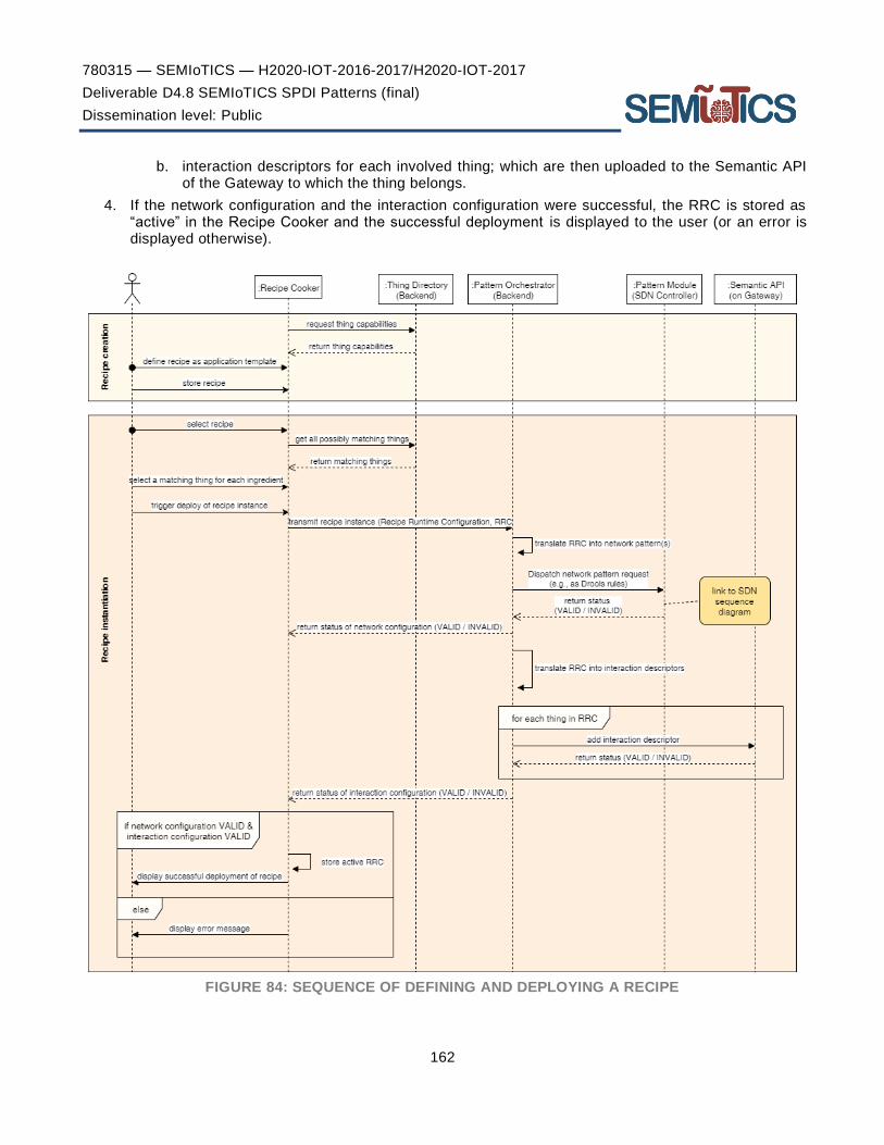
780315 — SEMIoTICS — H2020-IOT-2016-2017/H2020-IOT-2017
Deliverable D4.8 SEMIoTICS SPDI Patterns (final)
Dissemination level: Public
162
b. interaction descriptors for each involved thing; which are then uploaded to the Semantic API of the Gateway to which the thing belongs.
4. If the network configuration and the interaction configuration were successful, the RRC is stored as “active” in the Recipe Cooker and the successful deployment is displayed to the user (or an error is displayed otherwise).
FIGURE 84: SEQUENCE OF DEFINING AND DEPLOYING A RECIPE

780315 — SEMIoTICS — H2020-IOT-2016-2017/H2020-IOT-2017
Deliverable D4.8 SEMIoTICS SPDI Patterns (final)
Dissemination level: Public
163
6 RECIPES & PATTERNS INTEGRATION The integration of the Recipes approach detailed in section 5 above, with the SEMIoTICS SPDI patterns will enable the user-friendly, abstract definition of IoT service orchestrations, with the SPDI guarantees provided by the patterns. In more detail, the encoding of the dependencies will allow the verification that a specific SEMIoTICS service workflow, as defined in the associated Recipe, satisfies certain SPDI properties, but also the generation (and adaptation) of a workflow in a manner that guarantees the satisfaction of the needed SPDI properties
For integrating the user-friendly abstraction for IoT service orchestration provided by Recipes, the activity-based IoT orchestration model followed for Pattern definition, as detailed in Section 3, is mapped to the ingredient-based view of Recipes.
In more detail, Recipes are mapped to Workflows (i.e. orchestrations of activities), and similarly, the individual atomic building blocks are also mapped, i.e. ingredients are mapped to activities. A simple example of this is depicted in Figure 85, showing a simple Recipe involving two ingredients and a Workflow involving two activities that matches said Recipe.
FIGURE 85. A SIMPLE RECIPE (LEFT) AND A MATCHING WORKFLOW PATTERN (RIGHT)
The same match can happen in cases of more complex Recipes, whereby existing Recipes are used as ingredients to new, more complex recipes, since these can be mapped to sub-Workflows. An example of this mapping for a complex Recipe consisting of two ingredients, the second of which is another recipe, is depicted in Figure 86. The various Recipe parameters such as requirements, constraints, properties and orchestration details are also mapped to the corresponding elements in the workflow view.
FIGURE 86. A COMPLEX RECIPE (LEFT) AND A WORKFLOW PATTERN MATCHING SAID RECIPE (RIGHT)
Upon Recipe instantiation, the descriptions and characteristics of the specific offerings selected provide the necessary information needed to model the actual workflow and are passed over from Thing Descriptions of

780315 — SEMIoTICS — H2020-IOT-2016-2017/H2020-IOT-2017
Deliverable D4.8 SEMIoTICS SPDI Patterns (final)
Dissemination level: Public
164
the offerings to the various variables and placeholders present in the equivalent Workflow representation. For the Recipe shown in Figure 86, this transformation is visualised in Figure 87.
FIGURE 87. INSTATIATION OF RECIPE, REPLACING INGREDIENTS WITH SELECTED OFFERINGS (LEFT) AND INSTANTIATION OF WORKFLOW, REPLACING ACTIVITY PLACEHOLDERS WITH ACTUAL
ACTIVITIES (RIGHT)
The sequence diagrams for the interactions between the corresponding components of the SEMIoTICS architecture at design time and at runtime are depicted in Figure 88 and Figure 89 respectively. More specifically, Figure 88 shows the instantiation phase, where, following the Recipe definition and instantiation, via the Recipe Cooker module, the SPDI and QoS properties of the Recipe that are defined for the specific workflow are translated into the equivalent Pattern rules. These are in turn stored at the Pattern Global Repository and, via the Pattern Orchestrator, are sent to the Pattern Repositories residing in the lower layers (i.e. network and field), with each of those receiving the set of rules that pertains to the operation of the specific layer. At runtime (Figure 89), the Pattern Engines at each layer are responsible for retrieving, reasoning upon and updating the rules and facts stored on their local repositories, based on inputs they constantly receive from the Monitoring elements available at the various components at their layers that participate in the workflow. In the case of the Network and Field layers, any updates must be also relayed back at the Global repository, in order to allow it to have an up-to-date view of the state of the system at the various layers.
FIGURE 88. INSTANTIATION OF PATTERN COMPONENTS ACROSS LAYERS
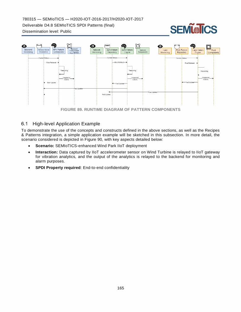
780315 — SEMIoTICS — H2020-IOT-2016-2017/H2020-IOT-2017
Deliverable D4.8 SEMIoTICS SPDI Patterns (final)
Dissemination level: Public
165
FIGURE 89. RUNTIME DIAGRAM OF PATTERN COMPONENTS
High-level Application Example
To demonstrate the use of the concepts and constructs defined in the above sections, as well as the Recipes & Patterns integration, a simple application example will be sketched in this subsection. In more detail, the scenario considered is depicted in Figure 90, with key aspects detailed below:
• Scenario: SEMIoTICS-enhanced Wind Park IIoT deployment
• Interaction: Data captured by IIoT accelerometer sensor on Wind Turbine is relayed to IIoT gateway for vibration analytics, and the output of the analytics is relayed to the backend for monitoring and alarm purposes.
• SPDI Property required: End-to-end confidentiality

780315 — SEMIoTICS — H2020-IOT-2016-2017/H2020-IOT-2017
Deliverable D4.8 SEMIoTICS SPDI Patterns (final)
Dissemination level: Public
166
FIGURE 90. EXAMPLE OF IIOT APPLICATION
DESIGN
The design of the “Windturbine Vibration Monitoring” Recipe implementing the above scenario is depicted in Figure 91, with ingredients “Vibration Analytics” and “Monitoring & Alarm”, as well as the Confidentiality property covering the whole Recipe. The matching Workflow would be a simple sequential workflow with two activities, much like the one shown on the right side of Figure 85.
FIGURE 91. THE WINDTURBINE VIBRATION MONITORING RECIPE
INSTANTIATION
When instantiating the above-defined Recipe, the appropriate offerings are selected to implement the desired process; e.g., the “Vibration Analytics Offering #1” offering is selected to implement the “Vibration Analytics” ingredient. Thus, the instantiated version of the recipe of Figure 91 is shown in Figure 92 (top) with the workflow view equivalent also appearing on the same figure (bottom). In the latter, the activity placeholders are replaced with specific activities (“Vibration Analysis” and “Monitoring Alarm”, respectively), with specifics on their

780315 — SEMIoTICS — H2020-IOT-2016-2017/H2020-IOT-2017
Deliverable D4.8 SEMIoTICS SPDI Patterns (final)
Dissemination level: Public
167
characteristics (e.g., inputs/outputs), as well as the end-to-end confidentiality property defined in the Recipe, which is now also broken down to individual properties for the two activities and the link between them.
FIGURE 92. INSTANTIATED RECIPE (TOP) AND WORKFLOW (BOTTOM)
Using the language defined in subsection 3.4, the above workflow can be formally described as follows:
0. ORCH “Seq2”
1. Placeholder (Placeholder1, (Vibration Analysis Activity, Vibration Analysis Description))
2. Placeholder (Placeholder2, (Monitoring Alarm Activity, Monitoring Alarm Description))
3. Sequence (Placeholder1, Placeholder2)
4. Link (Link1, Vibration Analysis, Monitoring Alarm)
5. Property (AP_1, Placeholder1, required, (certificate, interface), confidentiality, in_processing)
6. Property (AP_2, Link1, required, (pattern, “PSPpattern”), confidentiality, in_transit)
7. Property (AP_3, Placeholder2, required, (monitoring, interface), confidentiality, at_rest)
8. Property (OP, “Seq2”, required, (pattern-based, “PR1”), confidentiality, end_to_end)
9. Pattern rule: (PR1: AP_1, AP_2, AP_3 → OP)
A visualisation of the above rule for the specific scenario discussed, whereby the end-to-end confidentiality property of the workflow has to be evaluated by checking the individual AP (and if these hold, then the OP holds), is visualised in Figure 93 below.
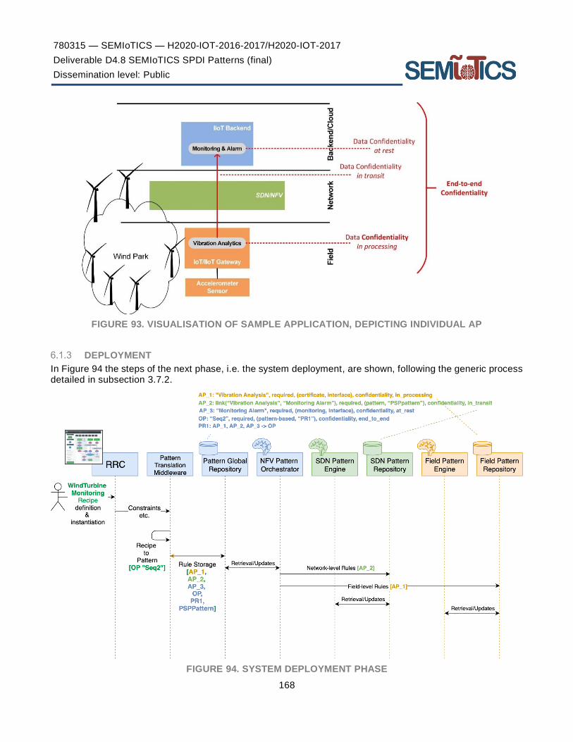
780315 — SEMIoTICS — H2020-IOT-2016-2017/H2020-IOT-2017
Deliverable D4.8 SEMIoTICS SPDI Patterns (final)
Dissemination level: Public
168
FIGURE 93. VISUALISATION OF SAMPLE APPLICATION, DEPICTING INDIVIDUAL AP
DEPLOYMENT
In Figure 94 the steps of the next phase, i.e. the system deployment, are shown, following the generic process detailed in subsection 3.7.2.
FIGURE 94. SYSTEM DEPLOYMENT PHASE

780315 — SEMIoTICS — H2020-IOT-2016-2017/H2020-IOT-2017
Deliverable D4.8 SEMIoTICS SPDI Patterns (final)
Dissemination level: Public
169
In more detail, following the transfer of the instantiation specifics from the Recipes plane to the Workflow pattern plane, the rules for the individual properties are stored on the Pattern Global Repository and then relayed by the Pattern Orchestrator to the pertinent layers for monitoring and verification; i.e. AP_1, at the IIoT gateway, AP_2 to the SDN Controller, while AP_3 only stays at the backend.
RUNTIME
At runtime, the individual SDN pattern engines collect monitoring data from the corresponding interfaces defined for each property at the specific layer’s components, reason on collected data and trigger adaptation actions if needed. Changes in the system state related to the monitored properties are stored as new facts or trigger updates in the stored facts in the corresponding Pattern repositories; for the network and field pattern engines, these are also transferred to the backend repository, to enable it to have an up-to-date global view of the SPDI state of the whole deployment. This process, again based on the generic scheme defined in subsection 3.7.2.2, is shown in Figure 95.
FIGURE 95. SYSTEM RUNTIME MONITORING AND ADAPTATION
Towards Pattern and Networking -aware IoT Application Development18
Based on the above defined concepts for recipes and patterns, we have developed tools to enable networking-aware IoT application development. While the composition of IoT applications is already well supported and is becoming easier, the focus is today solely on the flow and business logic of the application. The network between IoT devices and platforms is typically assumed as existing and not considered needing to be adjusted or managed by such IoT tools. Instead, today, the network is engineered separately and no integrated view on the application/network interplay is given. This is an issue as the network configuration underlying an IoT application can be crucial for its successful execution. This is getting particularly challenging if multiple IoT applications are implicitly relying on hard QoS constraints of the network. In this section, we present an integrative approach that allows the composition of IoT applications in conjunction with semantically-enabled requirement definitions towards the network.
To be able to define application flows with application-level networking requirements, we extended Distributed Node-RED (DNR) [107]. The DNR tool already provides a way to execute application flows in a distributed way, i.e., the IoT application developer can specify for each node of the application flow on which machine it should be deployed and executed. This makes DNR a powerful tool for realizing edge computing [108] applications. In the Figure 96 the DNR editor is shown and a simple application flow consisting of 4 nodes is implemented that transmits a live video between to Raspberry Pi devices. Labeled with 'piB', the start stream node and multipart decoder node (for decoding the video stream from a connected camera) are running on Raspberry Pi B. Similarly, the display image node is labeled with 'piA', which means that it is running on Raspberry Pi A. We could already connect the multipart decoder node and the display image node to create a distributed flow between Raspberry Pis A and B. However, with DNR only, no further specifications for the
18 This section is based on [106], published in the context of the SEMIoTICS project.

780315 — SEMIoTICS — H2020-IOT-2016-2017/H2020-IOT-2017
Deliverable D4.8 SEMIoTICS SPDI Patterns (final)
Dissemination level: Public
170
underlying networking can be made. Hence, we developed the DirectCom node, which is representing the network connection (see Figure 96)
FIGURE 96: LIVE VIDEO TRANSMISSION FLOW.
The main functionality of the DirectCom node is to create a UDP link between the source node on the left and destination node on the right. Using only the DNR without this extension, all communication (even the video data between the two nodes) happens via an MQTT server running in the background of DNR. The DirectCom node is running instances on all involved machines of the cluster (here: Raspberry Pi A and B). It launches a UDP server on the machine of the destination node and a UDP client on the machine of the source node, in order to transmit all incoming data from the source node (here: multipart decoder) to the UDP server node. In response, the UDP server forwards the received data to the next node (here: display image).
FIGURE 97: EXTENDED DISTRIBUTED NODE-RED (DNR) TO ALLOW THE SPECIFICATION OF
QUALITY OF SERVICE (QOS).
Figure 97 shows the configuration of the DirectCom node. Besides defining the IP addresses of source and destination, the socket port number of the UDP server, and the output data format (Buffer, String, or Base64 encoded string) have to be specified.
The QoS key text field in the dialog of Figure 97 then allows us to define application-level QoS constraints to be applied for this specific communication link. From a drop-down menu, terms that represent application-level QoS constraints can be selected. Here, 'schema:videoframerate' (set to a minimum of 15 frames per second) is provided to automatically translate the frame rate requirement of the application into a bandwidth constraint of a pattern. To integrate with an existing ecosystem we aligned our terms with the existing vocabulary schema.org [109].
To illustrate the above described tooling, we describe in the following an application for oil leakage detection occurring around the inner bearings of wind turbines, as defined in UC1. This leakage problem can remain

780315 — SEMIoTICS — H2020-IOT-2016-2017/H2020-IOT-2017
Deliverable D4.8 SEMIoTICS SPDI Patterns (final)
Dissemination level: Public
171
unrecognized for too long by the maintenance engineers and an automatic detection is promising for wind park operators.
The application flow is implemented in Node-RED and shown in Figure 98. The video stream from the camera is read via the 'video access' node. It transmits the video stream to an AI pipeline via the DirectCom node (Figure 97) that enables the definition of application-specific QoS constraints. In this example the video frame rate is specified to a minimum of 15 frames per second and configured/monitored by the Pattern Orchestrator and Pattern Engine. The AI pipeline can then load each image frame, transfers it to a tensor and finally classifies the image into two classes ('no oil' or 'oil' detected). The image classification is based on a re-trained MobileNet [110] neural network and is implemented using TensorFlow [111]. Finally, the programmable logic controller (PLC) for the wind turbine is triggered in case leaked oil is detected.
FIGURE 98: IOT APPLICATION FLOW FOR OIL LEAKAGE DETECTION.
Figure 9919 shows the deployment setup of this IoT application flow. The IT infrastructure within the wind turbine is connected via an SDN programmable network. Here, a Raspberry Pi device provides access to the video camera and a Siemens SIMATIC NanoBox is available on the network as an edge resource with extended computing power. First, the Recipe Cooker retrieves the relevant TDs for all registered devices to access their metadata. Then, the distributed application flow is defined in the Recipe Cooker as described above.
19 Icons made by Pause08, Becris, Eucalyp, and freepik from www.flaticon.com; images of NanoBox and PLC are under copyright of Siemens AG.

780315 — SEMIoTICS — H2020-IOT-2016-2017/H2020-IOT-2017
Deliverable D4.8 SEMIoTICS SPDI Patterns (final)
Dissemination level: Public
172
FIGURE 99: SETUP OF THE OIL LEAKAGE DETECTION APPLICATION.
In the second step, the application flow is translated to patterns and transmitted to the Pattern Orchestrator , which, in turn, forwards the accompanying workflow properties to the Pattern Engines to be monitored and enforced.
To achieve this, the output from the Recipe Cooker is formatted in JSON, the standard Node-RED flow export format, and relayed to the Pattern Orchestrator through APIs defined for that purpose and, more specifically, using a POST method request. The POST parameters include the recipe/flow (JSON format) as body and the header is application/json. The structure is presented in Figure 100.
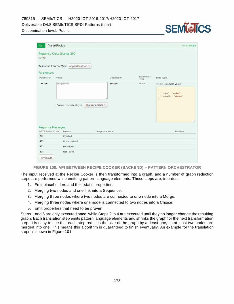
780315 — SEMIoTICS — H2020-IOT-2016-2017/H2020-IOT-2017
Deliverable D4.8 SEMIoTICS SPDI Patterns (final)
Dissemination level: Public
173
FIGURE 100. API BETWEEN RECIPE COOKER (BACKEND) – PATTERN ORCHESTRATOR
The input received at the Recipe Cooker is then transformed into a graph, and a number of graph reduction steps are performed while emitting pattern language elements. These steps are, in order:
1. Emit placeholders and their static properties.
2. Merging two nodes and one link into a Sequence.
3. Merging three nodes where two nodes are connected to one node into a Merge.
4. Merging three nodes where one node is connected to two nodes into a Choice.
5. Emit properties that need to be proven.
Steps 1 and 5 are only executed once, while Steps 2 to 4 are executed until they no longer change the resulting graph. Each translation step emits pattern language elements and shrinks the graph for the next transformation step. It is easy to see that each step reduces the size of the graph by at least one, as at least two nodes are merged into one. This means this algorithm is guaranteed to finish eventually. An example for the translation steps is shown in Figure 101.

780315 — SEMIoTICS — H2020-IOT-2016-2017/H2020-IOT-2017
Deliverable D4.8 SEMIoTICS SPDI Patterns (final)
Dissemination level: Public
174
FIGURE 101. FROM RECIPE GRAPH INTO PATTERN LANGUAGE
At the same time, the application flow is deployed using DNR, i.e., each node contained in the application is instantiated within the Node-RED environment of the device to which it has been assigned.
In this application, a live video stream is transmitted between a Raspberry Pi and a NanoBox over a network configured by an SDN controller. In order to evaluate the influence of the SEMIoTICS approach and particularly the utilization of the DirectCom node and specified QoS in the application flow (see Figure 98), we compared the brokered architecture (as an indirect communication using MQTT via the original DNR broker as part of the Recipe Cooker) and the direct communication (using UDP with the DirectCom node). To compare the latency, a timestamp packet was sent from Raspberry Pi every one second; once it arrived at the NanoBox, another timestamp was generated, and the difference was calculated as latency (or end-to-end delay). We did this procedure for both approaches.
The resulting latency measurements over time are presented in Figure 102. In the graph, it becomes clear that over time the direct communication approach has less latency than the brokered architecture approach. It has been reduced around 50%.
FIGURE 102: PERFORMANCE MEASUREMENTS OF ANALYSIS APPLICATION IN DIRECT VS. INDIRECT MODE.
Further, we analysed the difference in received throughput between the two approaches. To do that, 1000 messages per second were sent from the Raspberry Pi, every message is about 73 Bytes. In the NanoBox, we checked how many messages were received per second. We did this procedure for both approaches.

780315 — SEMIoTICS — H2020-IOT-2016-2017/H2020-IOT-2017
Deliverable D4.8 SEMIoTICS SPDI Patterns (final)
Dissemination level: Public
175
The measured throughput over time is shown in a graph of Figure 102. From the graph, we can see that the direct communication approach has better throughput (received messages/second) compared to the brokered architecture approach and it improves by around 50%. As an early verification of the pattern reasoning approach, a proof of concept environment has been setup based on the JBoss Drools Engine v7.1520, deployed on a desktop system (Core i7, 8GB RAM), loading the Pattern Engine with a basic set of Drools rules. A test client is used to make calls to the Pattern Engine to request verification of the QoS pattern rule presented in this scenario (i.e., an adaptation of the pattern rule shown in subsection 4.5.1). Using the above test setup and based on the complexity of the modelled IoT environment, i.e., the number of placeholders stored as facts within the Drool knowledge base, the execution time ranges from 19 ms for 10 placeholders to 82 ms for 100 placeholders. While a more detailed performance evaluation will follow, investigating in more detail the performance impact of modelling more complex environments and supporting and evaluation a larger set of pattern rules, these initial results validate the feasibility of real-time pattern-driven property verification and the timely triggering of needed adaptations.
20 https://www.drools.org/download/download.html

780315 — SEMIoTICS — H2020-IOT-2016-2017/H2020-IOT-2017
Deliverable D4.8 SEMIoTICS SPDI Patterns (final)
Dissemination level: Public
176
7 PATTERN-DRIVEN MONITORING & ADAPTATION IN THE SEMIOTICS USE CASES
An important part of the SEMIoTICS vision is the semi-autonomic operation and the cross-layer intelligent dynamic adaptation in IoT and IIoT environments, of which the pattern-driven adaptations developed within T4.1 and presented herein are a fundamental enabler. In this context, this section aims to highlight the pattern-driven monitoring and adaptations at the various layers of the SEMIoTICS deployment in the context of the SEMIoTICS use cases.
Two different types of pattern-driven orchestration adaptations are envisioned: i) at design-time, and ii) at runtime.
When changes are imposed to the IoT service orchestration in order for an SPDI or QoS orchestration property to be valid at design-time, these changes must be communicated back where the description of the orchestration has been created (in this case, the Recipe Cooker component). The recipient of the changes is the end user that needs to confirm them. As soon as the said changes have been accepted by the user (or automatically accepted based on a set of predefined user preferences), the new, updated IoT service orchestration is deployed. Such a change could be the replacement of a component with another component (or a combination of components; e.g. when a device fails to comply to certain properties, such as because of an expired certification) or even the addition of an extra component into the orchestration to make sure that two services in sequence are interoperable (e.g., a semantic mediator; alterations at the output of the first service are undertaken by the extra component, thus constituting it compatible with the input of the second service).
On the other hand, when the imposed changes have to be done at runtime, there is no need to be communicated back to the end user. In this case, the best fitted change is chosen and the needed actions are taken, however the end user is not informed. For example, let us assume that the IoT service orchestration in question has a Camera component. If, for a reason, the Camera becomes unavailable, another component from the IoT repository with the same functionality and the same SPDI/QoS properties is selected to replace the one that has become unavailable. In that way the initial property of the whole orchestration, before the unavailability event, is not affected and continues to hold. Nevertheless, informing the backend orchestration component (i.e. Recipe Cooker) may be needed in this case for visualization purposes, to ensure that the GUI depicts an up-to-date orchestration state.
In addition to the above generic example demonstrating the use of the integrated pattern-driven IoT orchestration approach, the subsections below present related consideration focusing on the use cases of SEMIoTICS.
Use case 1 – Oil leakage detection in wind turbines recipe definition, deployment, monitoring and adaptation
In Figure 103 a topology is depicted that corresponds to use case 1 of the project, elaborating on the concept presented in subsection 6.2. In this topology a Camera that is connected on a Raspberry Pi captures a video that is sent through a switch to a second Raspberry Pi. On the second Raspberry a video player is deployed, which depicts the captured video. On this orchestration patterns can be leveraged to monitor and ensure at the network level that certain QoS properties are maintained in terms of bandwidth to ensure the uninterrupted and smooth video playback. In that context, the application designer will be able to specify through the Recipe Cooker GUI the desired QoS properties, these will be translated to patterns and relayed to the corresponding Pattern Engine (in this case the Pattern Engine embedder into the SDN Controller) for monitoring and enforcement, per the process described in subsection 6.1.

780315 — SEMIoTICS — H2020-IOT-2016-2017/H2020-IOT-2017
Deliverable D4.8 SEMIoTICS SPDI Patterns (final)
Dissemination level: Public
177
FIGURE 103: USE CASE 1 ORCHESTRATION
Such an orchestration could be described using the IoT pattern language as:
0. ORCH “QoSBandwidth”
1. Softwarecomponent("Camera"),
2. Property("Prop0", required, qosbandwidth, "11400000.0", in_processing, "Camera", true),
3. Softwarecomponent("VideoPlayer"),
4. Property("Prop1", required, qosbandwidth, "11400000.0", in_processing, "VideoPlayer", true),
5. Link("Link1", "Camera", "VideoPlayer"),
6. Property("Prop2", required, qosbandwidth, "11400000.0", in_transit, "Link1", true),
7. Sequence("Seq1", "Camera", "VideoPlayer", "Link1"),
8. Property("Prop3", required, qosbandwidth, "50000", end_to_end, "Seq1", false)
9. Pattern rule: (PR1: Prop0, Prop1, Prop2 → Prop3)
In this context, the subsections that follow will document the adaptation process enabling the semi -autonomous intelligent adaptation of the system when a violation of a desired property occurs.
ORCHESTRATION ADAPTATION DUE TO SPDI/QOS VIOLATION
ADAPTATION PROCESS
When an existing IoT service orchestration does not satisfy a required SPDI/QoS property due to a particular orchestration component, it might be possible to replace the responsible component in order to restore the required property.
This adaptation action is handled by the algorithm listed below. This algorithm starts by trying to find appropriate components based on a query (Q) expressing structural, behavioral and security requirements for the component that should be modified. To do this, it is needed to identify Things that can provide the requested functionality by searching in an instance, global or local, of Thing Directory. The Thing Directory is an open -source directory for Thing Descriptions (TDs). It can be used to browse and discover Things based on their TDs and features an API to create, read, update and delete (CRUD) a TD.
The aforementioned query Q returns a Thing for each component that does not satisfy an SPDI/QoS property, based on the described structural, behavioral and security requirements. As a result, the response of a query Q is a list of Things named Substitute List. The Substitute List is used for the creation of a new IoT service

780315 — SEMIoTICS — H2020-IOT-2016-2017/H2020-IOT-2017
Deliverable D4.8 SEMIoTICS SPDI Patterns (final)
Dissemination level: Public
178
orchestration derived from the original one, where the components that do not satisfy an SPDI/QoS property are replaced by the corresponding Things including in the Substitute List.
ACTION SEQUENCE
The SEMIoTICS components that take part in the adaptation process described so far are the Recipe Cooker, Thing Directory, Pattern Orchestrator, and the Pattern Engines of the three layers (Backend, Network, Field). The sequence diagram below shows the interaction among them. The diagram is split into two parts. The first part shows the interactions until the end of the verification of an end-to-end SPDI/QoS property. The second part focuses on the adaptation actions, if needed.
Firstly, the Recipe Cooker is used for the description of the IoT service orchestration in the form of a Recipe. The created Recipe includes the instances of the components that constitute the orchestration, potentially some of their SPDI/QoS properties and the end-to-end SPDI/QoS property that is desired for the whole orchestration.
This Recipe is communicated to Pattern Orchestrator after first translating it into the dedicated pattern language. Pattern Orchestrator receives the Recipe, parses it deconstructing it into its basic elements (orchestrations, orchestrationActivities, Links, etc.). Each of these elements is sent to the appropriate Pattern Engine in order to be added as Drools Facts into the Drools working memory of the Engine. Additional information from the SEMIoTICS monitoring components is also communicated and added as Drools Facts in the Drools working memory of each Pattern Engine in every layer. Drools Facts in combination with pre-existing Drools Rules reason for the final status of the said end-to-end SPDI/QoS property (verification process).
If the status of the end-to-end SPDI/QoS property, at the end of the verification process, is TRUE, it is sent to the Recipe Cooker, through the Pattern Orchestrator and no further action is needed.
On the other hand, if the status is FALSE, it is also sent to the Recipe Cooker triggering at the same time a series of adaptation actions. The first of these adaptation actions, done by the Pattern Engine, is the identification of the orchestration components that are responsible for the fact the end-to-end SPDI/QoS property in question does not hold. These are the components that must be replaced by Things contained in the Thing Directory. After that, for every component to be replaced a request is made to the Thing Directory asking for a substitute that conforms to specific structural, behavioral and security requirements, as already described above. Thing Directory responds with the candidate substitutes, which are added in the so called substitute-list. In case, more than one candidate Thing is included in the response, a selection of the optimal one can take place based on some criteria such as resource consumption.
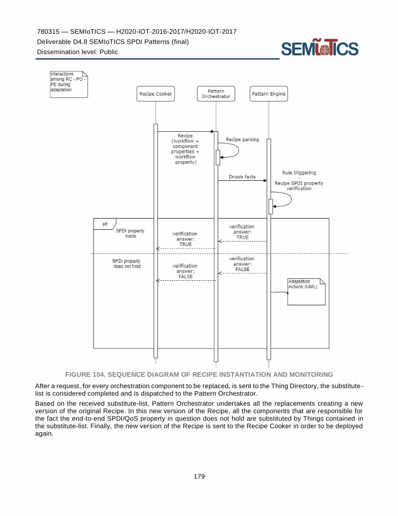
780315 — SEMIoTICS — H2020-IOT-2016-2017/H2020-IOT-2017
Deliverable D4.8 SEMIoTICS SPDI Patterns (final)
Dissemination level: Public
179
FIGURE 104. SEQUENCE DIAGRAM OF RECIPE INSTANTIATION AND MONITORING
After a request, for every orchestration component to be replaced, is sent to the Thing Directory, the substitute-list is considered completed and is dispatched to the Pattern Orchestrator.
Based on the received substitute-list, Pattern Orchestrator undertakes all the replacements creating a new version of the original Recipe. In this new version of the Recipe, all the components that are responsible for the fact the end-to-end SPDI/QoS property in question does not hold are substituted by Things contained in the substitute-list. Finally, the new version of the Recipe is sent to the Recipe Cooker in order to be deployed again.
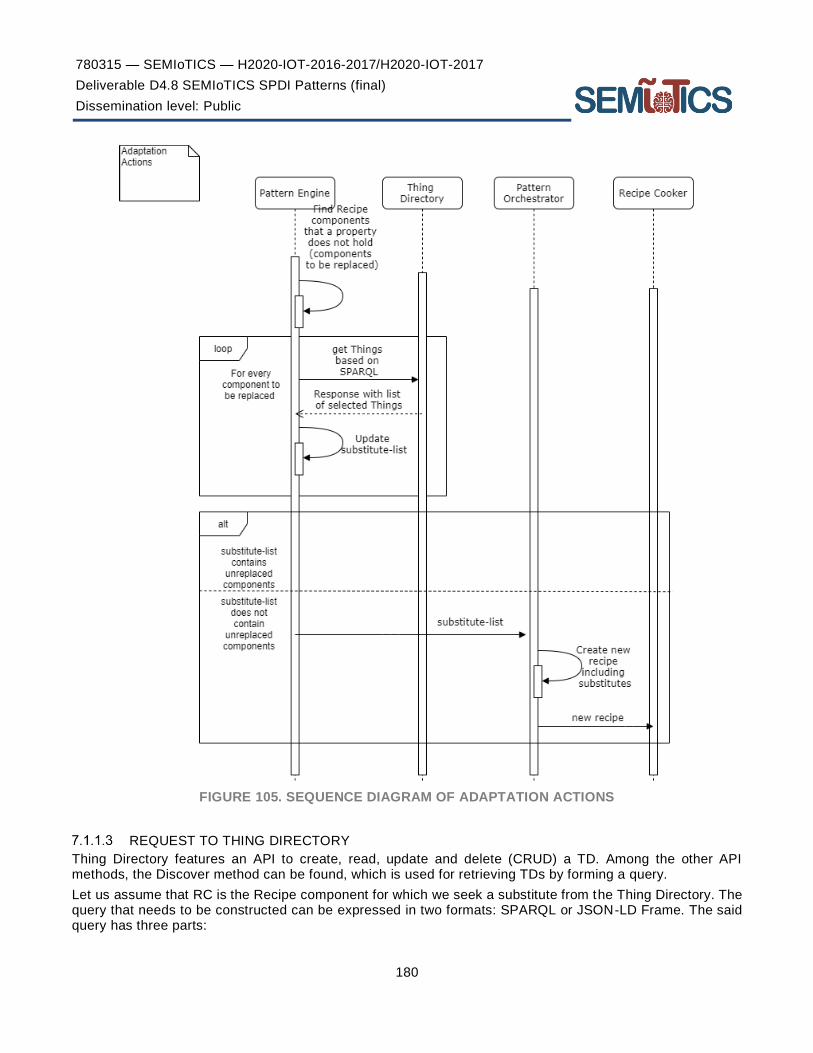
780315 — SEMIoTICS — H2020-IOT-2016-2017/H2020-IOT-2017
Deliverable D4.8 SEMIoTICS SPDI Patterns (final)
Dissemination level: Public
180
FIGURE 105. SEQUENCE DIAGRAM OF ADAPTATION ACTIONS
REQUEST TO THING DIRECTORY
Thing Directory features an API to create, read, update and delete (CRUD) a TD. Among the other API methods, the Discover method can be found, which is used for retrieving TDs by forming a query.
Let us assume that RC is the Recipe component for which we seek a substitute from the Thing Directory. The query that needs to be constructed can be expressed in two formats: SPARQL or JSON-LD Frame. The said query has three parts:
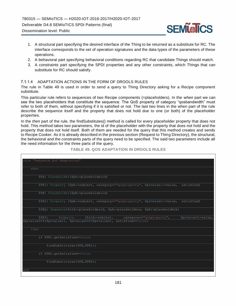
780315 — SEMIoTICS — H2020-IOT-2016-2017/H2020-IOT-2017
Deliverable D4.8 SEMIoTICS SPDI Patterns (final)
Dissemination level: Public
181
1. A structural part specifying the desired interface of the Thing to be returned as a substitute for RC. The
interface corresponds to the set of operation signatures and the data types of the parameters of these
operations.
2. A behavioral part specifying behavioral conditions regarding RC that candidate Things should match.
3. A constraints part specifying the SPDI properties and any other constraints, which Things that can
substitute for RC should satisfy.
ADAPTATION ACTIONS IN THE FORM OF DROOLS RULES
The rule in Table 49 is used in order to send a query to Thing Directory asking for a Recipe component substitute.
This particular rule refers to sequences of two Recipe components (=placeholders). In the when part we can see the two placeholders that constitute the sequence. The QoS property of category “qosbandwidth” must refer to both of them, without specifying if it is satisfied or not. The last two lines in the when part of the rule describe the sequence itself and the property that does not hold due to one (or both) of the placeholder properties.
In the then part of the rule, the findSubstitutes() method is called for every placeholder property that does not hold. This method takes two parameters, the id of the placeholder with the property that does not hold and the property that does not hold itself. Both of them are needed for the query that this method creates and sends to Recipe Cooker. As it is already described in the previous section (Request to Thing Directory), the structural, the behavioral and the constraints parts of the query need to be specified. The said two parameters include all the need information for the three parts of the query.
TABLE 49. QOS ADAPTATION IN DROOLS RULES
rule "Sequence QoS Adaptation"
when
$PA: Placeholder($pA:=placeholderid)
$PR1: Property ($pA:=subject, category=="qosproperty", $prvalue1:=value, satisfied)
$PB: Placeholder($pB:=placeholderid)
$PR2: Property ($pB:=subject, category=="qosproperty", $prvalue2:=value, satisfied)
$SEQ: Sequence($sId:=placeholderid, $pA:=placeholdera, $pB:=placeholderb)
$PR3: Property ($sId:=subject, category=="qosproperty", $prvalue3:=value,
$prvalue3=f($prvalue1), $prvalue3=f($prvalue2), satisfied==false)
then
if $PR1.getSatisfied==false
findSubstitutes($PA,$PR1);
if $PR2.getSatisfied==false
findSubstitutes($PB,$PR2);
end

780315 — SEMIoTICS — H2020-IOT-2016-2017/H2020-IOT-2017
Deliverable D4.8 SEMIoTICS SPDI Patterns (final)
Dissemination level: Public
182
Use case 2 – Adaptable Security services chaining in Ambient Assisted Living environments
In Figure 106 an orchestration is depicted that corresponds to the use of a chain of network service functions used in the context use case 2 (healthcare/ambient assisted living scenario). Grouping them based on the different traffic types involved in the use case, five different service chains are designed:
• Chain 1 – Mobile Phone: Firewall -> DPI -> IDS -> Output
• Chain 2 – Robotic Rolator: Firewall -> IDS -> Load Balancer -> Output
• Chain 3 – Smart Home: Firewall -> IDS -> Output
• Chain 4 – Robot: Firewall -> Load Balancer -> Output
• Chain 5 - Malicious: Firewall -> Honeypot
In this case, patterns can be leveraged to reason about the different SPDI and QoS properties of the different chains, since each of the different security service functions (e.g., IDS) provide different guarantees and other functions (e.g., load balancer) provide QoS-related guarantess. For the sake of brevity, and without loss of generality, as these scenarios will be defined and demonstrated further in future deliverables when the implementation of all involved components is mature, we focus on the first chain: the mobile phone of a patient sends an output to the doctor, through three software components to guarantee the security property of their communication. The three software components that compose the said chain are: i) Firewall; ii) Data Packet Inspection and iii) Intrusion Detection System.
FIGURE 106: USE CASE 2 ORCHESTRATION
Such an orchestration could be described using the IoT pattern language as:
0. ORCH “Security”
1. Placeholder(“MobilePhone”, "macaddress", "activityaddress"),
2. Softwarecomponent ("Firewall"),
3. Link("Link1", “MobilePhone”, "Firewall"),
4. Sequence(“Seq1”, “MobilePhone”, "Firewall", “Link1”),
5. Softwarecomponent ("DPI"),
6. Link("Link2", "Seq1", "DPI"),
7. Sequence(“Seq2”, "Seq1", "DPI", “Link2”),
8. Softwarecomponent ("IDS"),
9. Link("Link3", "Seq2", "IDS"),
10. Sequence(“Seq3”, "Seq2", "IDS", “Link3”),
11. Placeholder ("Doctor"),
12. Link("Link4", "Seq3", "Doctor"),

780315 — SEMIoTICS — H2020-IOT-2016-2017/H2020-IOT-2017
Deliverable D4.8 SEMIoTICS SPDI Patterns (final)
Dissemination level: Public
183
13. Sequence(“Seq4”, "Seq3", "Doctor", “Link4”),
14. Property("Prop0", required, security, "1", end_to_end, "Seq4", false)
The subsections that follow present more details into the building blocks and mechanisms enabling the pattern-driven monitoring and adaptation in the context of this scenario.
SERVICE FUNCTION CHAINING -BASED PATTERN-DRIVEN ADAPTATIONS
SECURITY BASED ON SECURITY SERVICE FUNCTION CHAINING
Service Function Chaining (SFC) provides the ability to define an ordered list of network services and virtual network functions (VNFs) to create a service chain on network topologies. More specifically, VNFs can be used for various tasks related to security and privacy in secure industrial infrastructures, such as the SEMIoTICS use cases, and deployed as virtualized network service functions as proactive mechanisms able to provide SPD monitoring management. A list of VNFs for proactive SPD property monitoring includes the following functions: Intrusion Detection System (IDS) / Intrusion Prevention System (IPS), Firewall, Deep Packet Inspection (DPI), Network Virtualization, Access Control Lists, Packet inspectors, HoneyNet and load balancers. In addition to only inspection of packets as in DPI, VNFs can also modify data packets. For example, for protection of confidentiality of data, a VNF can implement an IPSec tunnel. Key distribution for IPSec is also facilitated by the security manager in the network and backend layers.
By appropriately leveraging the flexibility of SDN/NFV-enabled networks in the context of the adopted security mechanisms, industrial infrastructures can not only match but also improve their security posture compared to the existing, traditional networking environments. More specifically, for the pattern language, it is essential that properties for security and privacy can be monitored and enforced. In order to classify the SPD properties that each service function chain can satisfy, Table 50 depicts this correlation properties and functions. Thus, a pattern can check whether an information flow includes, e.g. a required VNF for anonymization. In addition, if a pattern determines that a certain property needs to be enforced, it can add a VNF for this purpose to the respective information flow.
TABLE 50. SPD PROPERTIES IN SERVICE FUNCTIONS
Privacy Security Dependability
Functions Access Control
Confidentiality Integrity Availability Reliability
Firewall o o
IDS/IPS o o o
DPI o o
IPSec o o o
Load-balancer o o
HoneyPot/Net o o o
SERVICE FUNCTION CHAINING PATTERNS Service Function Chaining Patterns provide the ability to define an ordered list of security network services (e.g. firewalls, DPIs, IDS) for security in network infrastructures by creating chains at design and by updating function in chains based on available ones at runtime. SFC patterns should cover the placement, security and scalability aspect of SEMIoTICS network infrastructures. The deployment of network service functions can be used to guarantee specific network security and dependability properties. However, stitched them into chains

780315 — SEMIoTICS — H2020-IOT-2016-2017/H2020-IOT-2017
Deliverable D4.8 SEMIoTICS SPDI Patterns (final)
Dissemination level: Public
184
can satisfy more than one SPD properties. One of the innovative approaches supported by this work, is the dynamic instantiation of SFCs based on the predefined SFC patterns. When there is a request for an SFC instantiation containing service functions, the depicted in Figure 107 procedure should be followed. If the SFC does not exist, the instantiation of the respective SFC is deployed through the identification of the requested VNFs. If the VNFs exist in the service nodes, the SFC is updated including these VNFs. If the VNFs do not exist, the service node with the available resources is requested to instantiate the respective VNFs. The procedure is ended when all the requested VNFs are included in the SFC.
FIGURE 107 VNF INSTANTIATION BASED ON SFC REQUEST
To proceed to the above description, SFC patterns are developed to achieve the requirement for end to end guarantees by the traffic forwarding through different security service functions. The patterns can be expressed as Drools rules to enforce the following requirements:
• Verify service function chains on chain requests • Instantiate service function chains, if the required functions have been already instantiated. • Verify functions to insert the in the request chain • Instantiate not defined service functions to satisfy service function chain requests.
VERIFY SERVICE FUNCTION CHAINS ON SFC REQUESTS
When there is a request to forward the traffic from src to destination dst through a chain{vnf1,vnf2,..},
the verification of the chain existence is required. If the service chain(vnf1,vnf2,…) has been instantiated,
the property requirement for chain request will be satisfied.
TABLE 51. VERIFICATION OF SERVICE FUNCTION CHAINING PATTERN
1. rule "Service Function Chaining Chain Verification"
2. salience 10
3. ruleflow-group "SFC"
4. when
5. $src: Placeholder($srcName: name)
6. $dst: Placeholder ($dstName: name)
Chain Verification Pattern
Chain Instantiation Pattern
Function Verification Pattern
Function Instantiation Pattern

780315 — SEMIoTICS — H2020-IOT-2016-2017/H2020-IOT-2017
Deliverable D4.8 SEMIoTICS SPDI Patterns (final)
Dissemination level: Public
185
7. $function: Function($type:=type, instantiated==true)
8. $chain: Chain($functions: functions, $functions contains $function,
instantiated==true)
9. $PR: Property($src:=src, $dst:=dst, $reqFunctions:=property.chain.functions,
satisfied== false)
10. then
11. System.out.println("Verification of Chain");
12. modify($PR){satisfied=true};
13. end
INSTANTIATE SERVICE FUNCTION CHAINS
When the chain is not included in the chain list, it should be instantiated. However, this is related to the existence of the requested by the chain VNFs. The pattern rule is able to search whether the network functions (network service instances) are running in the VIM. This can be done by the reception of the required information by the NFV Mano regarding the up and running network service instances. When the required VNFs exists, then a new chain can be instantiated.
TABLE 52. INSTANTIATION OF SERVICE FUNCTION CHAINING PATTERN
1. rule "SFC Chain Instantiation"
2. ruleflow-group "SFC"
3. salience 20
4. when
5. $src: Placeholder($srcName: name)
6. $dst: Placeholder($dstName: name)
7. $function: Function($type:=type, instantiated==true)
8. $chain: Chain($functions: functions, $functions contains $function,
instantiated==false)
9. $PR: Property($src:=src, $dst:=dst, $reqFunctions:=property.chain.functions,
satisfied== false)
10. Function($type==type) from $reqFunctions
11. then
12. System.out.println("Instantiation of Chain");
13. modify($chain){instantiated=true};
14. end
VERIFICATION OF VIRTUAL NETWORK FUNCTIONS
To instantiate the chain, it is required to identify whether the functions have been instantiated. For that reason. the function verification pattern is presented in order to verify the existence of the required by the chain functions.
TABLE 53. VERIFICATION OF SERVICE FUNCTIONS PATTERN
1. rule "Virtual Service Network Function Verification"
2. ruleflow-group "SFC"
3. salience 30
4. when
5. $src: Placeholder($srcName: name)
6. $dst: Placeholder($dstName: name)
7. $function: Function($type:=type, instantiated==true)
8. $chain: Chain($functions: functions, $functions not contains $function,
instantiated==false)
9. $PR: Property($src:=src, $dst:=dst, $reqFunctions:=property.chain.functions,
satisfied== false)

780315 — SEMIoTICS — H2020-IOT-2016-2017/H2020-IOT-2017
Deliverable D4.8 SEMIoTICS SPDI Patterns (final)
Dissemination level: Public
186
10. Function($type==type) from $reqFunctions
11. then
12. System.out.println("Verification of Function");
13. $chain.addFunction($function);
14. update($chain);
15. end
INSTANTIATE VIRTUAL NETWORK FUNCTIONS TO SATISFY SERVICE FUNCTION CHAIN REQUESTS
Finally, the last rule is able to instantiate the required network functions to satisfy the chain request, when the required functions have not been instantiated in the VIM. Following this procedure, all the requested functions {vnf1, vnf2,..} are instantiated based on the existence of the available VNFs images or descriptors. More
specifically, the first step includes the search on the available service descriptors. The second step includes the creation of the network service. The third step includes the actual instantiation of the network service as a vnf to be included in the chain. And since the required {vnf1, vnf2,..} will exist, the chain can be
instantiated as described previously.
TABLE 54. INSTANTIATION OF SERVICE FUNCTION CHAINING PATTERN
1. rule "Virtual Service Network Function Instantiation"
2. ruleflow-group "SFC"
3. salience 40
4. when
5. $src: Placeholder($srcName: name)
6. $dst: Placeholder ($dstName: name)
7. $function: Function($type:=type, instantiated==false)
8. not Function($type:=type, instantiated==true)
9. $chain: Chain($functions: functions, $functions not contains $function,
instantiated==false)
10. $PR: Property($src:=src, $dst:=dst, $reqFunctions:=property.chain.functions,
satisfied== false)
11. Function($type==type) from $reqFunctions
12. then
13. System.out.println("Instantiation of Function");
14. Function function = new Function($function.type);
15. modify($function){instantiated=true};
16. 16. end
SFC PATTERNS IN THE SEMIOTICS ARCHITECTURE
The procedure of instantiation and the identification of the respective SFCs and the VNFs of the Figure 108 can be based on the previously described patterns. More specifically, this can be based on the actual interaction between the components of the SEMIoTICS architecture. Pattern Orchestrator forwards a specific chain request to the Pattern Engine for forwarding the traffic between entities through a specific chain of functions. Pattern Engine forwards this request to the SFC manager which is located in the SDN controller responding to the Pattern Engine whether the chain exists or not. If the chain exists, then a respond of the chain satisfaction is returned to the Pattern Orchestrator. If the chain does not exist, then a requested is forwarded from the MANO requesting whether the service functions exist or not. If functions exist in the VIM, then the chain can be instantiated in the SFC Manager and a respond of the chain satisfaction is returned to the Pattern Orchestrator. If functions do not exist in the VIM then, a function instantiation request is forwarded to the NFV Orchestrator, which is responsible to instantiate them in the VIM. Then, the chain can be instantiated in the SFC Manager and a respond of the chain satisfaction is returned to the Pattern Orchestrator.

780315 — SEMIoTICS — H2020-IOT-2016-2017/H2020-IOT-2017
Deliverable D4.8 SEMIoTICS SPDI Patterns (final)
Dissemination level: Public
187
FIGURE 108, SEMIOTICS SFC PATTERN INSTANTIATION
To enable such capability, the use of the SFC pattern rules as enforced through the Pattern Orchestrator and the Pattern Engine at the backend are required. Considering the above, there is significant motivation to leverage the flexibility provided by SFC to define specific service chains for each type of traffic. By applying the previous described procedure of chain instantiation, the legacy SARA use case can be extended to support traffic forwarding through specific service functions. That includes the traffic forwarding for the different type of traffic exchanged between the different actors as will be described in the pattern in SEMIoTICS use cases.
Finally, apart from the control flow configuration, the data flow is required to support service chaining. That can include the instantiation of the requested paths to interconnect the end-hosts through the instantiated service function chains, the associated service functions and the respective switches. However, this related to existing topology that could be either virtual or physical deployed.
ABE-ENCRYPTION FOR CONFIDENTIALITY PROTECTION FOR DATA AT REST
The Security Manager includes the identity management of all entities inside the SEMIoTICS architecture, this ranges from the devices, services to the human users of the IoT deployment. Furthermore, it contains the ability to generate keys for encryption and decryption of data based on the attributes the entity has. This is known as Attribute based encryption (short ABE). With ABE you can request to encrypt data for not only an entity or a list of entities, but also for a set of attributes. This allows to specify during encryption that only entities with the attribute that their role is doctors (“role=doctors”) would be able to later decrypt the
encrypted data. The encrypted data is thus protected for confidentiality against outsiders and against any entity that does not have the attributes. Of course, the ABE also allows to encrypt for the conjunction of attributes.

780315 — SEMIoTICS — H2020-IOT-2016-2017/H2020-IOT-2017
Deliverable D4.8 SEMIoTICS SPDI Patterns (final)
Dissemination level: Public
188
ABE encryption can be done without the need to know the keys of intended recipients. Let us elaborate with a small example: ABE encryption can be used by one SEMIoTICS application or service to store data on an external storage provider. This ensures that confidentiality of the stored encrypted data is upheld even though this storage provider is outside the scope of SEMIoTICS and thus does not allow the access control and its enforcement by PEP or other means as with SEMIoTICS integrated applications. Then at a later time another application or service, that wants to retrieve the data, where that second application or service is a inside the SEMIoTCS deployment, will be able to retrieve a decryption key based on the attributes of the entity on which behalf the application or service is running. If the attributes match or are a superset of those that were selected during encryption, the second application will be able to successfully decrypt the data.
Thus, ABE allows to implement and enforce access control policies to uphold confidentiality requirements cryptographically. Especially, useful is
1. the loose coupling between encryption and decryption, so that during encryption the there is no need to interact with the entity that later is allowed to decrypt and vice versa, and
2. the fact that due to strong cryptographic guarantees this enforcement of access control can be extended to third party storage services.
If data is needed to be stored outside of SEMIoTICS access control, e.g. external cloud storage, the data can be encrypted using ABE-functionality offered by the security manager in the backend, the details are described in D4.12 (and its predecessor D4.5) and in the respective deliverables for the technical API of the Securit y Manager in the backend (D4.13).
Use case 3 – Local Embedded Intelligence at field layer with dependable sensing
In Figure 109 a topology is depicted that corresponds to the scenario of use case 3, and more specifically distributed anomaly vibration monitoring for earthquake detection. In this scenario, we consider that a Gateway is connected to N vibration sensors (where N>=3 for redundancy), which are identical. At any time, all of them are up and running, for redundancy in the monitoring. This redundant topology can be modelled and monitored as the Dependability property, through the appropriately defined pattern rule. Therefore, the infrastructure owner will be able to monitor in real-time the dependability status of his/her deployment, potentially triggering adaptations (e.g., the disabling of one sensor while waiting for a replacement).
FIGURE 109: USE CASE 2 TOPOLOGY
Such an orchestration could be described using the SEMIoTICS pattern language as:

780315 — SEMIoTICS — H2020-IOT-2016-2017/H2020-IOT-2017
Deliverable D4.8 SEMIoTICS SPDI Patterns (final)
Dissemination level: Public
189
0. ORCH “Dependability”
1. Iotsensor ("VibrationSensor1", "activityaddress", "activityport"),
2. Iotsensor ("VibrationSensor2", "activityaddress", "activityport"),
3. Iotgateway ("Gateway", "activityaddress", "activityport"),
4. Link("Link1", "VibrationSensor1", "Gateway"),
5. Link("Link2", "VibrationSensor2", "Gateway"),
6. Merge("Merge1", "VibrationSensor1", "VibrationSensor2", "Gateway", "Link1", "Link2"),
7. Property("Prop0", required, dependability, "1", end_to_end, "Merge1", false)
The subsections that follow present more details into the building blocks and mechanisms enabling the pattern-driven monitoring and adaptation in the context of this scenario.
SENSING DEPENDABILITY REAL-TIME MONITORING
As mentioned, the scenario revolves around unsupervised monitoring from environmental sensors with anomaly detection (from temperature, pressure, humidity), as well as unsupervised monitoring from inertial sensors with anomaly detection (from accelerometer and gyroscope). Considering the criticality of the application, revolving around earthquake monitoring in public areas, it is envisioned that sensor dependability is of very high importance. Therefore, and to avoid system downtime, redundant sensors will be deployed to ensure that even if some sensors fail, the system will continue to operate.
In this context, pattern components are deployed at the field layer (which is the focus of UC3), with the support of components deployed at the backed for visualisation purposes. Regarding the former, a pattern engine runs on the Gateway, able to reason locally about the dependability properties of the anomaly detection setup.
Said Pattern Engine will be a lightweight version of the engines deployed in other scenarios, and will feature appropriate Dependability Pattern Rule to verify that this Dependability property is satisfied and, in case that a sensor fails, will be able to reason and report the failure of the property to the backend. When the sensor is restored, reasoning will verify that the dependability property is restored.
A sequence diagram depicting the involved entities as well as the events taking place in the scenario in terms of the pattern-based dependability monitoring is provided in Figure 110.

780315 — SEMIoTICS — H2020-IOT-2016-2017/H2020-IOT-2017
Deliverable D4.8 SEMIoTICS SPDI Patterns (final)
Dissemination level: Public
190
FIGURE 110. REAL-TIME PATTERN-BASED SENSING DEPENDABILITY MONITORING SEQUENCE
In terms of the pattern rule to be employed in the specific scenario, and since dependability is of focus, the Redundancy Pattern will be leveraged, as defined in subsection 4.3.2. Adapting said pattern to the specific use case would result in a Drools rule as the one shown in Table 55.
TABLE 55. SENSING REDUNDANCY PATTERN AS DROOLS RULES
rule "Redundancy Verification"
when
$p1: Placeholder($pID1:=placeholderID)
$p2: Placeholder($pID2:=placeholderID, name=”Sensor 1”, $placeholerType1:=type,
type=vibrationSensor)
$p3: Placeholder($pID3:=placeholderID, name=”Sensor 2”, $placeholerType1:=type,
$placeholerType1==$placeholerType2)

780315 — SEMIoTICS — H2020-IOT-2016-2017/H2020-IOT-2017
Deliverable D4.8 SEMIoTICS SPDI Patterns (final)
Dissemination level: Public
191
$ch: Choice($chID:=id, $ pID1:=placeholderA, $pID2:=placeholderB, $pID3:=placeholderC) $pr: Property($chID:=subject, category=="Redundancy", satisfied==false)
Then
modify($pr2){satisfied=true};
end
The when part of the rule specifies:
1. the placeholders $p1, $p2 and $p3; 2. the extra condition that placeholder 2 and 3 are of the same type; 3. the order in which they should be executed ($ch), 4. the orchestration property that can be guaranteed through the application of the pattern, i.e., the
Redundancy property in this case ($pr).
The then part verifies that the orchestration property holds since every essential component is included in the when part (satisfied=true).
If additional actions need to integrated into the scenario, then Fault Management aspects can also be included, leveraging the corresponding pattern defined in subsection 4.3.3.
Other envisioned adaptations
In addition to the use case -focused scenarios examined in the previous subsections, there is a plethora of additional monitoring and adaptation cases that can be supported by SEMIoTICS, by combining the pattern -driven reasoning and adaptation mechanisms (mainly defined and developed within Task 4.1, and detailed in this deliverable) with the project’s various security mechanisms (mainly defined and developed within Task 4.5, and documented in D4.12). The subsections that follow aim to highlight the potential of this interplay between patterns and the security mechanisms.
REPLICATION OF SECURITY MANAGER FUNCTIONALITY (PEP AND PAP) INTO THE GATEWAY
To support a fast and accessible adaptation of security-based mechanisms in connection with the security manager there is the possibility of a local policy decision & administration replica of the gateway security manager endpoint positioned on the field device. In specific, it means that a subset of the security manager's functionality is replicated so that it can be distributed to the local field gateways and then operated independently of the central security manager components located in the backend. In the various scenarios, there may be several security managers for several reasons, for example if there are several domains which have their own identity provision and their own authorisation policies then there will be a Backend Security Manager in each domain. Of course, several replicated security managers at the field level can be managed by a single Security Manager in the backend. In Figure 111 you can see some of the potential deployment situations.

780315 — SEMIoTICS — H2020-IOT-2016-2017/H2020-IOT-2017
Deliverable D4.8 SEMIoTICS SPDI Patterns (final)
Dissemination level: Public
192
FIGURE 111. DIFFERENT POTENTIAL DEPLOYMENT SCENARIOS OF REPLICATED SECURITY
MANAGERS
Pattern-driven customization capabilities can provide increased efficiency where lower latency and less external communication can be service critical. This also enhances the availability of the overall construct, since it is independent of the latency of the security manager in the backend. Another significant aspect is the increased data protection, as there is less external communication on the field level. Physical security in the field can be ensured by a Trusted Platform Module (TPM). The TPM extends the field device (e.g. a Raspberry Pi) by basic security functions. Utilizing these makes it possible to store cryptographic keys, which enables a secure communication with the security manager in the backend. Furthermore, the system can in that way be protected against manipulation by software and unbidden persons. This can be very advantageous, because the field device might be deployed in an environment in which manipulation by third parties cannot be entirely prevented.
Remark that the replicated security manager only implements the functionalities of PEP and PAP locally. Under normal circumstances, the local version attempts to obtain the policy decision straight from the back -end security manager (for PDP functionality) or to update the policy directly in the back-end security manager's database (for PAP functionality). However, if these direct requests are not possible, the replicated shadow instance tenders the functionality available locally and synchronizes with the back end again as soon as it is possible. With this local fallback, policy enforcement can still work with a local view of the policy. Besides, the policy decision point could be configured to deny access if the last contact with the back end was too long ago.
CONFIDENTIALITY, INTEGRITY AND ORIGIN-AUTHENTICATION BY END-TO-END ENCRYPTION FROM IOT DEVICES TO END-POINTS USING TLS
Another adaptation that can happen with the involvement of devices in the field is the ability to enable confidentiality, integrity and origin authentication from the IoT devices to their desired endpoints by enabling end-to-end encryption. Devices would announce possible encryption options during bootstrapping. This provides the opportunity that these devices could turn-on a TLS-encrypted connection on-demand as soon as a pattern that needs this level of security identifies that the communication to the corresponding endpoint requires encryption. A possible example would be the activation of TLS when the IoT device (client) communicates using the MQTT-protocol over a communication channel for which the SDN cannot establish a secure enough channel with the corresponding MQTT-broker (server).
The advantage of this whole pattern-based TLS enablement would be that it would save computing capacity on the IoT device for interactions when the added level of security offered by the TLS-encryption is unnecessary. This provides the ability to trade security and privacy with efficiency and speed where needed by the application via the respective pattern.

780315 — SEMIoTICS — H2020-IOT-2016-2017/H2020-IOT-2017
Deliverable D4.8 SEMIoTICS SPDI Patterns (final)
Dissemination level: Public
193
8 CONCLUSIONS This deliverable, being the final output of Task 4.1 (“Architectural SPDI Patterns”) presented the requirements, design process and the final versions of the IoT Application and Orchestration model, and the associated SEMIoTICS SPDI pattern language. Moreover, based on the later, the full set of patterns of SEMIoTICS were also presented, covering all SPDI properties, as well as QoS and IoT Orchestration composition and decomposition patterns. In addition to these properties, the set of provided patterns covers all data states, as well as all states of platform connectivity.
This deliverable also presented implementation aspects that were key to the realisation of the pattern-driven orchestrations across all layers of the architecture, also covering pattern-driven adaptations within and across all layers of the SEMIoTICS architecture, which are at the core of the SEMIoTICS vision of multi-layered embedded intelligence and semi-autonomic operation.
Furthermore, the integration of the above pattern-based approach with the service orchestration definition via the Recipes approach was presented, along with key implementation aspects and results, enabling the user-friendly definition of IoT Applications with SPDI and QoS guarantees at design-time and at runtime.
Finally, a detailed presentation was provided for the role of the patterns and the associated pattern components in the three use cases that are the focus of the project, tailored to the intricacies of each use case, but also balanced to showcase different aspects of the pattern-driven capabilities of the SEMIoTICS framework on each use case, motivated by said intricacies of each use case environment.
As the SPDI pattern-drive approach is at the core of the SEMIoTICS concept and vision, significant effort has been spent in verifying/validating said approach, including the process followed to design and implement it, and the resulting enabling mechanisms. In more detail, these validation efforts included:
(1) The verification/validation of the process used to define the SPDI patterns is indirectly provided by following an established and structure methodology, whereby a system model is defined, followed by the associated language/grammar derivation, and followed by the specification of the rules using said mechanisms, and leveraging the associated reasoning mechanisms that can automatically process aid rules (see section 3 above).
(2) The verification/validation of the defined SPDI properties (that are then encoded as pattern rules) from a conceptual/theoretical perspective is achieved by relying on peer-reviewed sources through a literature survey, to identify established patterns adopting, modifying and extending them, per the needs of the project and its use cases (see subsection 4.6 above).
(3) The underlying model's consistency is mainly verified in terms of UML model specification constraints (relationships, naming etc.), as imposed by the toolset used to define it (as its definition is UML based - see subsection 3.3 above).
(4) The validation of the derived workflow and SPDI rule specifications in terms of correctness with regards to the SEMIoTICS language (and associated EBNF grammar) derived from the above model is achieved on the fly by the ANLTR4 lexer/parser, when these specifications are translated into Drools rules (see subsection 3.8 of D4.8).
(5) The validation of the derived Drools rules is provided at runtime by the Drools rule engine (see subsection 3.7.1 above)
(6) From an implementation perspective the above have been validated and evaluated in the context of the project's Use Cases, where the SPDI patterns and the relevant implementation building blocks were featured prominently (see deliverables D5.9, D5.10, D5.11, for UC1, UC2 and UC3, respectively).
(7) Finally, the whole SPDI pattern-driven SEMIoTICS approach, as sketched in this deliverable, also encompassing (1)-(6) above, along with the associated results have been validated from an academic perspective through a significant number of publications to high-impact venues that has been achieved by the consortium, whereby this approach and its evolution has been presented extensively. Key publications include the following:
• Journals:
780315 — SEMIoTICS — H2020-IOT-2016-2017/H2020-IOT-2017
Deliverable D4.8 SEMIoTICS SPDI Patterns (final)
Dissemination level: Public
194
– "Defining IoT Orchestrations with Security and Privacy by Design: A Gap Analysis", M. Papoutsakis, K. Fysarakis, G. Spanoudakis, and S. Ioannidis, IEEE Internet of Things Magazine, Mar. 2021
– "Towards a Collection of Security and Privacy Patterns", M. Papoutsakis, K. Fysarakis, G. Spanoudakis, S. Ioannidis, and K. Koloutsou, MDPI Applied Sciences, 11(4), 1396, 2021. (DOI: 10.3390/app11041396)
– "Networking-Aware IoT Application Development", A. Bröring, J. Seeger, M. Papoutsakis, K. Fysarakis, and A. Caracalli, MDPI Sensors, 20(3), 897, 2020. (DOI: 10.3390/s20030897)
• Conferences:
– "A Pattern–Driven Adaptation in IoT Orchestrations to Guarantee SPDI Properties", M. Papoutsakis, K. Fysarakis, E. Michalodimitrakis, E. Lakka, N. Petroulakis, G. Spanoudakis, and S. Ioannidis, 2nd Model-Driven Simulation and Training Environments for Cybersecurity (MSTEC), co-located with the European Symposium on Research in Computer Security (ESORICS), Guildford, UK, 17 Sept. 2020.
– “Towards IoT Orchestrations with Security, Privacy, Dependability and Interoperability Guarantees", K. Fysarakis, M. Papoutsakis, N. Petroulakis, and G. Spanoudakis, 2019 IEEE Global Communications Conference (GLOBECOM), Waikoloa, HI, USA, Dec. 9-13, 2019.
– “Pattern-driven Security, Privacy, Dependability and Interoperability management of IoT environments", O. Soultatos, M. Papoutsakis, K. Fysarakis, G. Hatzivasilis, M. Michalodimitrakis, G. Spanoudakis, and S. Ioannidis, 2019 24th IEEE International Workshop on Computer-Aided Modeling Analysis and Design of Communication Links and Networks (CAMAD), Limassol, Cyprus, Sept. 11-13, 2019.
– "Architectural Patterns for Secure IoT Orchestrations", K. Fysarakis, G. Spanoudakis, N. Petroulakis, O. Soultatos, A. Bröring, and T. Marktscheffel, Global IoT Summit 2019 (GIoTS'19), Aarhus, Denmark, June 17-21, 2019.
Through these efforts, the deliverable directly addresses the first key objective of WP4, which is to “Define a language for specifying machine interpretable SPDI patterns and develop patterns encoding horizontal and vertical ways of composing parts of IoT applications that can evidently guarantee SPDI properties across heterogeneous smart objects and components from all layers of the IoT application implementation stack ”. Most importantly, and as noted in subsection 2.6, it directly addresses the first of the main project objectives (Objective 1: Development of patterns for orchestration of smart objects and IoT platform enablers in IoT applications with guaranteed security, privacy, dependability and interoperability (SPDI) properties ), and the associated KPIs.
While the submission of this deliverable also signifies the end of Task 4.1, efforts on refining the concepts presented herein will continue. More specifically, refining and integrating the components, and the pattern -driven capabilities in general, as presented herein, will continue in the context of the integration (i.e., Task 3.5 – Implementation of Field-level middleware & networking toolbox, Task 4.6 – Implementation of SEMIoTICS backend API, Task 5.2 – Software system integration, Task 5.3 – IIoT Infrastructure set-up and testing) and demonstration (i.e., Task 5.4 – Demonstration and validation of IWPC- Energy scenario, Task 5.5 – Demonstration and validation of SARA-Health scenario, Task 5.6 – Demonstration and validation of IHES-Generic IoT scenario) tasks of the project.

780315 — SEMIoTICS — H2020-IOT-2016-2017/H2020-IOT-2017
Deliverable D4.8 SEMIoTICS SPDI Patterns (final)
Dissemination level: Public
195
REFERENCES [1] W. Stallings, L. Brown, M. D Bauer, and A. K. Bhattacharjee, “Computer security: principles and
practice” (pp. 978-0). Upper Saddle River, NJ, USA: Pearson Education, 2012.
[2] A. Lukacs, "What Is Privacy ? the History and Definition of Privacy," p. 256–265, 2017.
[3] M. Dennedy et al., "The Privacy Engineer’s Manifesto: Getting from Policy to Code to QA to Value," Apress, p. 400, 2014.
[4] E. Union, "Regulation 2016/679 of the European parliament and the Council of the European Union," Off. J. Eur. Communities, vol. 2014, p. 1–88, 1995.
[5] I. C. Office, "Anonymisation: managing data protection code of practice," Inf. Comm. Off., p. 106, 2012.
[6] P. Ohm, "Broken Promises of Privacy: Responding to the Surprising Failure of Anonymization," UCLA Law Rev., vol. 57, p. 1701–1777, 2010.
[7] ISO/IEC 27018, 2014. [Online]. Available: http://www.iso27001security.com/html/27018.html.
[8] ISO/IEC 29100:2011, 1996. [Online]. Available: https://www.iso.org/obp/ui/#iso:std:iso-iec:29100:ed-1:v1:en.
[9] CDC, "HIPAA Privacy Rule and Public Health Guidance from CDC and the U . S . Department depar," vol. 52, p. 24, 2003.
[10] W. Al-mawee, "Privacy and Security Issues in IoT Healthcare Applications for the Disabled Users a Survey," 2012.
[11] M. F. Mushtaq, S. Jamel, A. H. Disina, Z. A. Pindar, N. S. A. Shakir, and M. M. Deris, "A Survey on the Cryptographic Encryption Algorithms", Int. J. Adv. Comput. Sci. Appl., vol. 8, p. 333–344, 2017.
[12] W. Arthur, D. Challener, and K. Goldman, "A Practical Guide to TPM 2.0," Statew. Agric. L. Use Baseline, p. 375, 2015.
[13] J. Laprie, "Dependable computing and fault-tolerance," in Digest of Papers FTCS-15, 1985.
[14] A. Geraci, F. Katki, L. McMonegal, B. Meyer, J. Lane, P. Wilson, J. Radatz, M. Yee, H. Porteous, and F. Springsteel, "IEEE standard computer dictionary: Compilation of IEEE standard computer glossaries," 1991. doi: 10.1109/IEEESTD.1991.106963
[15] P. Park, P. Di Marco, C. Fischione, and K. Johansson, "Modeling and optimization of the ieee 802.15. 4 protocol for reliable and timely communications," Parallel and Distributed Systems, vol. 24, 2013, doi: 10.1109/TPDS.2012.159
[16] J. Chen, J. Chen, F. Xu, M. Yin, and W. Zhang, “When software defined networks meet fault tolerance: A survey,” in Lecture Notes in Computer Science (including subseries Lecture Notes in Artificial Intelligence and Lecture Notes in Bioinformatics), 2015, doi: 10.1007/978-3-319-27137-8_27.
[17] G. Aful., "Definition: Interoperability.," 2018. [Online]. Available: http://interoperability -definition.info/en/. [Accessed 20 August 2018].
[18] J. Kiljander e. a., "Semantic interoperability architecture for pervasive computing and Internet of Things," IEEE Access, vol. 2, pp. 856-873, doi:10.1109/ACCESS.2014.2347992, 2014.
[19] B. Haslhofer and W. Klas, “A survey of techniques for achieving metadata interoperability,” ACM Comput. Surv., vol. 42, no. 2, pp. 1–37, Feb. 2010, doi: 10.1145/1667062.1667064.
[20] A. Bröring, A. Schmid, S. Schindhelm, C. Kim, A. Khelil,, S. Kabisch, D. Kramer, D. Phuoc, J. Mitic, D. Anicic, E. Teniente. (2017). Enabling IoT Ecosystems through Platform Interoperability. IEEE Software. 34. 54-61. doi: 10.1109/MS.2017.2. P. Barnaghi, W. Wang, C.A. Henson and K. Taylor, "Semantics for the Internet of Things: Early Progress and Back to the Future. International Journal on Semantic Web & Information Systems," International journal on Semantic Web and information systems, 2012.

780315 — SEMIoTICS — H2020-IOT-2016-2017/H2020-IOT-2017
Deliverable D4.8 SEMIoTICS SPDI Patterns (final)
Dissemination level: Public
196
[21] Abowd G. D., Allen R., and Garlan D., “Formalizing style to understand descriptions of software architecture”, ACM Transactions on Software Engineering and Methodology (TOSEM), 4(4), 319-364, 1995.
[22] Schumacher M., “Security engineering with patterns: origins, theoretical models, and new applications”, Vol. 2754, Springer Science & Business Media, 2003.
[23] C. Alexander, “The Timeless Way of Building,” New York Oxford University Press. 1979, doi: 10.1080/00918360802623131.
[24] P. Barnaghi, W. Wang, C. Henson, K. Taylor. “Semantics for the Internet of Things: Early Progress and Back to the Future. International Journal on Semantic Web & Information Systems.” 8., 2012, doi:10.4018/jswis.2012010101.
[25] T. Baker, M. Asim, H. Tawfik, B. Aldawsari and R. Buyya, "An energy-aware service composition algorithm for multiple cloud-based IoT applications," Journal of Network and Computer Applications, pp. 96-108, 2017.
[26] Z. Zhou, D. Zhao, L. Lui and P. C. K. Hung, "Energy-aware composition for wireless sensor networks as a service," Future Generation Computer Systems, pp. 299-310, 2018.
[27] O. Alsaryrah, I. Mashal and T. Chung, "Energy-Aware Services Composition for Internet of Things," in IEEE 4th World Forum on Internet of Things, Singapore, 2018.
[28] A.Urbieta, A. Gonzalez-Beltran, S. B. Mokhtar, M. A. Hossain and L. Capra, "Adaptive and context-aware service composition for IoT-based smart cities," Future Generation Computer Systems, pp. 262-274, 2017.
[29] L. Chen and C. Englund, "Choreographing Services for Smart Cities: Smart Traffic Demonstration," in IEEE 85th Vehicular Technology Conference (VTC Spring), Sydney, 2017.
[30] J. Seeger, R. A. Deshmukh and A. Broring, "Running Distributed and Dynamic IoT Choreographies," in Global IoT Summit (GIoTS), Bilbao, 2018.
[31] C.Forgy, "Rete: A Fast Algorithm for the Many Pattern/Many Object Pattern Match Problem," Artificial Intelligence, vol. 19, p. 17–37, 1982.
[32] M. Hafiz, P. Adamczyk, and R. E. Johnson, “Towards an Organization of Security Patterns,” IEEE Softw. Spec. Issue Softw. Patterns, vol. 24, no. 4, pp. 52–60, 2007.
[33] D. Ritter and S. Rinderle-Ma, “Towards a Collection of Cloud Integration Patterns,” CoRR, vol. abs/1511.09250, 2015.
[34] D. E. Denning, "A lattice model of secure information flow," Communications of the ACM, vol. 19, pp. 236-243, 1976.
[35] D. M. Kienzle, M. C. Elder, D. Tyree, and J. Edwards-Hewitt, “Security patterns repository version 1.0,” DARPA, Washingt. DC, 2002.
[36] M. Schumacher, E. Fernandez-Buglioni, D. Hybertson, F. Buschmann, and P. Sommerlad, Security Patterns: Integrating Security and Systems Engineering. 2006.
[37] N. Ahituv, Y. Lapid, and S. Neumann, “Processing encrypted data,” Commun. ACM, vol. 30, no. 9, pp. 777–780, Sep. 1987, doi: 10.1145/30401.30404.
[38] W. Ding, Z. Yan, and R. H. Deng, “Encrypted data processing with Homomorphic Re-Encryption,” Inf. Sci. (Ny)., vol. 409–410, pp. 35–55, Oct. 2017, doi: 10.1016/j.ins.2017.05.004.
[39] K. S. Ahluwalia and A. Jain, “High availability design patterns,” in Proceedings of the 2006 conference on Pattern languages of programs - PLoP ’06, 2006, p. 1, doi: 10.1145/1415472.1415494.
[40] ISO/IEC 27000:2018, “Information technology — Security techniques — Information security management systems — Overview and vocabulary”, 2018
[41] C. Steel, R. Nagappan, and R. Lai. “Core Security Patterns: Best Practices and Strategies for J2EE(TM), Web Services, and Identity Management,” Prentice Hall PTR, Oct 2005

780315 — SEMIoTICS — H2020-IOT-2016-2017/H2020-IOT-2017
Deliverable D4.8 SEMIoTICS SPDI Patterns (final)
Dissemination level: Public
197
[42] X.509 Digital Certification - Microsoft. [Online]. Available: https://docs.microsoft.com/en-us/windows/win32/seccrypto/x-509-digital-certification
[43] Kerberos Authentication Overview – Microsoft. [Online]. Available: https://docs.microsoft.com/en-us/windows-server/security/kerberos/kerberos-authentication-overview
[44] A. Durand, J. P Andreaux, and T. Sirvent,, U.S. Patent No. 7,545,932. Washington, DC: U.S. Patent and Trademark Office, 2009.
[45] Two-way Authentication – IBM. [Online]. Available: https://www.ibm.com/support/knowledgecenter/SSRMWJ_7.0.1/com.ibm.isim.doc/securing/cpt/cpt_ic_security_ssl_scenario.htm
[46] MySQL Cluster documentation. [Online]. Available: http://dev.mysql.com/doc/refman/5.1/en/ndbcluster.html
[47] G. Hatzivasilis et al., “The Interoperability of Things: Interoperable solutions as an enabler for IoT and Web 3.0.", In 2018 IEEE 23rd International Workshop on Computer Aided Modeling and Design of Communication Links and Networks (CAMAD) (pp. 1-7). IEEE, 2018, September.
[48] A. Zakinthinos, and E. S. Lee, "A general theory of security properties," in IEEE Symposium on Security and Privacy, 1997.
[49] M. Maidi, "The common fragment of CTL and LTL.," in Foundations of Computer Science, 2000.
[50] A. Avizienis, J.C. Laprie , B. Randell , "Fundamental Concepts of Dependability," in LAAS-CNRS, 2001.
[51] M. Hafiz, “A collection of privacy design patterns,” in Proceedings of the 2006 conference on Pattern languages of programs - PLoP ’06, 2006, p. 1, doi: 10.1145/1415472.1415481.
[52] M. Hafiz, “A pattern language for developing privacy enhancing technologies,” Softw. Pract. Exp., vol. 43, no. 7, pp. 769–787, Jul. 2013, doi: 10.1002/spe.1131.
[53] T. Schümmer, “The public privacy - patterns for filtering personal information in collaborative systems,” Proc. CHI Work. Human-Computer-Human-Interaction Patterns, no. 1963, pp. 1–35, 2004, doi: 10.1.1.528.1860.
[54] M. Schumacher, “Security Patterns and Security Standards - With Selected Security Patterns for Anonymity and Privacy,” Eur. Conf. Pattern Lang. Programs, 2003.
[55] A. Pfitzmann and M. Hansen, “A terminology for talking about privacy by data minimization: Anonymity, Unlinkability, Undetectability, Unobservability, Pseudonymity, and Identity Management,” Tech. Univ. Dresden, 2010, doi: 10.1.1.154.635.
[56] J. C. Caiza, Y. S. Martín, J. M. Del Alamo, and D. S. Guamán, “Organizing design patterns for privacy: A taxonomy of types of relationships?,” in ACM International Conference Proceeding Series, 2017, doi: 10.1145/3147704.3147739.
[57] C. Kalloniatis, E. Kavakli, and S. Gritzalis, “Addressing privacy requirements in system design: the PriS method,” Requir. Eng., vol. 13, no. 3, pp. 241–255, Sep. 2008, doi: 10.1007/s00766-008-0067-3.
[58] ISO/IEC 29100:2011, “Information technology — Security techniques — Privacy framework”, 2011.
[59] ISO/IEC 15408-2:2008, “Information technology -- Security techniques -- Evaluation criteria for IT security -- Part 2: Security functional components,” 2008.
[60] V. Diamantopoulou, N. Argyropoulos, C. Kalloniatis, and S. Gritzalis, “Supporting the design of privacy -aware business processes via privacy process patterns,” in Proceedings - International Conference on Research Challenges in Information Science, 2017, doi: 10.1109/RCIS.2017.7956536.
[61] S. Fischer-Hübner, IT-Security and Privacy: Design and Use of Privacy-Enhancing Security Mechanisms. Berlin, Heidelberg: Springer-Verlag, 2001.
[62] Common Criteria, “Common Criteria for Information Technology Security Evaluation - Part 2 : Security functional components,” Version 3.1, Rev. 5, 2017.

780315 — SEMIoTICS — H2020-IOT-2016-2017/H2020-IOT-2017
Deliverable D4.8 SEMIoTICS SPDI Patterns (final)
Dissemination level: Public
198
[63] C. Kuhn, M. Beck, S. Schiffner, E. Jorswieck, and T. Strufe, “On Privacy Notions in Anonymous Communication,” Proc. Priv. Enhancing Technol., vol. 2019, no. 2, pp. 105–125, Apr. 2019, doi: 10.2478/popets-2019-0022.
[64] G. W. Van Blarkom, J. J. Borking and J. G. E. Olk, “Handbook of Privacy and Technologies The case of Intelligent Software Agents Handbook of Privacy and Privacy-Enhancing Technologies The case of Intelligent Software Agents,” Privacy Incorporated Software Agent (PISA) Consortium, The Hague, 2003, 198.
[65] Commission of the European Communities, “Communication from the Commission to the European Parliament and the Council on Promoting Data Protection by Privacy Enhancing Technologies (PETs),” in COM (2007) 228 final, 2007.
[66] A. Pfitzmann and M. Waidner, “Networks without user observability,” Comput. Secur., vol. 6, no. 2, pp. 158–166, Apr. 1987, doi: 10.1016/0167-4048(87)90087-3.
[67] A. Pfitzmann, "Diensteintegrierende Kommunikationsnetze mit teilnehmerüberprüfbarem Datenschutz", Informatik-Fachberichte 234, Springer-Verlag, 1990.
[68] D. L. Chaum, “Untraceable electronic mail, return addresses, and digital pseudonyms,” Commun. ACM, vol. 24, no. 2, pp. 84–90, Feb. 1981, doi: 10.1145/358549.358563.
[69] D. Chaum, “The dining cryptographers problem: Unconditional sender and recipient untraceability,” J. Cryptol., vol. 1, no. 1, pp. 65–75, Jan. 1988, doi: 10.1007/BF00206326.
[70] D. Goldschlag, M. Reed, and P. Syverson, “Onion routing,” Commun. ACM, vol. 42, no. 2, pp. 39–41, Feb. 1999, doi: 10.1145/293411.293443.
[71] R. Dingledine, N. Mathewson, and P. Syverson, “Tor: The second-generation onion router,” in Proceedings of the 13th USENIX Security Symposium, 2004.
[72] L. Sweeney, “k-Anonymity: A model for protecting privacy,” Int. J. Uncertainty, Fuzziness Knowledge -Based Syst., vol. 10, no. 05, pp. 557–570, Oct. 2002, doi: 10.1142/S0218488502001648.
[73] A. Machanavajjhala, D. Kifer, J. Gehrke, and M. Venkitasubramaniam, “ℓ -diversity: Privacy beyond k-anonymity,” ACM Trans. Knowl. Discov. Data, 2007, doi: 10.1145/1217299.1217302.
[74] N. Li, T. Li, and S. Venkatasubramanian, “t-Closeness: Privacy Beyond k-Anonymity and l-Diversity,” in 2007 IEEE 23rd International Conference on Data Engineering, 2007, pp. 106–115, doi: 10.1109/ICDE.2007.367856.
[75] K. Fysarakis, C. Manifavas, I. Papaefstathiou, and A. Adamopoulos, “A lightweight anonymity and location privacy service,” in IEEE International Symposium on Signal Processing and Information Technology , 2013, pp. 000124–000129, doi: 10.1109/ISSPIT.2013.6781866.
[76] A. Pfitzmann, B. Pfitzmann, and M. Waidner, “ISDN-Mixes: Untraceable Communication with Very Small Bandwidth Overhead,” 1991, pp. 451–463.
[77] D. Chaum, “Security without identification: transaction systems to make big brother obsolete,” Commun. ACM, vol. 28, no. 10, pp. 1030–1044, Oct. 1985, doi: 10.1145/4372.4373.
[78] D. Chaum, “Showing credentials without identification transferring signatures between unconditionally unlinkable pseudonyms,” in Advances in Cryptology — AUSCRYPT ’90, Berlin/Heidelberg: Springer-Verlag, 1990, pp. 245–264.
[79] G. Danezis, R. Dingledine, and N. Mathewson, “Mixminion: Design of a type III anonymous remailer protocol,” in Proceedings - IEEE Symposium on Security and Privacy, 2003, doi: 10.1109/SECPRI.2003.1199323.
[80] J. Camenisch and E. Van Herreweghen, “Design and implementation of the idemix anonymous credential system,” in Proceedings of the ACM Conference on Computer and Communications Security, 2002, doi: 10.1145/586111.586114.
[81] M. D. Mulvenna, S. S. Anand, and A. G. Büchner, “Personalization on the Net using Web mining: introduction,” Commun. ACM, vol. 43, no. 8, pp. 122–125, Aug. 2000, doi: 10.1145/345124.345165.

780315 — SEMIoTICS — H2020-IOT-2016-2017/H2020-IOT-2017
Deliverable D4.8 SEMIoTICS SPDI Patterns (final)
Dissemination level: Public
199
[82] Registratiekamer, the Netherlands and Information and Privacy Commissioner, Privacy-Enhancing Technologies: The Path to Anonymity, Volume II, Achtergrondstudies en Verkenningen 5B, Rijswijk, 1995.
[83] A. Gabel and I. Schiering, “Privacy Patterns for Pseudonymity,” in IFIP Advances in Information and Communication Technology, 2019, pp. 155–172.
[84] A. Pfitzmann and M. Kohntopp, “Anonymity, unobservability, and pseudonymity – A proposal for terminology,” in Lecture Notes in Computer Science (including subseries Lecture Notes in Artificial Intelligence and Lecture Notes in Bioinformatics), 2001, doi: 10.1007/3-540-44702-4_1.
[85] N. Provos and P. Honeyman, “Hide and seek: an introduction to steganography,” IEEE Secur. Priv., vol. 1, no. 3, pp. 32–44, May 2003, doi: 10.1109/MSECP.2003.1203220.
[86] M. Nutzinger, C. Fabian, and M. Marschalek, “Secure Hybrid Spread Spectrum System for Steganography in Auditive Media,” in 2010 Sixth International Conference on Intelligent Information Hiding and Multimedia Signal Processing, 2010, pp. 78–81, doi: 10.1109/IIHMSP.2010.27.
[87] V. Korzhik, G. Morales-Luna, K. Loban, and I. Marakova-Begoc, “Undetectable spread-time stegosystem based on noisy channels,” in Proceedings of the International Multiconference on Computer Science and Information Technology, 2010, pp. 723–728, doi: 10.1109/IMCSIT.2010.5680048.
[88] J. Zöllner, H.Federrath, A.Pfitzmann, A.Westfeld, G.Wicke, G.Wolf, "Über die Model lierung steganographischer Systeme", Proceedings GIFachtagung ´Verlässliche Informationssysteme´ VIS´97, Eds.: G.Müller et al., Freiburg, 30.9.-2.10.97, Vieweg-Verlag.
[89] J. C. Laprie et al., "Dependability: Basic Concepts and Terminology," in Springer-Verlag, ISBN, 1992.
[90] N. E. Petroulakis, G. Spanoudakis, and I. G. Askoxylakis, “Patterns for the design of secure and dependable software defined networks,” Comput. Networks, vol. 109, pp. 39–49, Nov. 2016, doi: 10.1016/j.comnet.2016.06.028.
[91] H. van der Veer, A. Wiles, Achieving Technical Interoperability – the ETSI Approach, April 2008 ETSI White Paper No. 3, [Online]. Available: http://www.etsi.org/images/files/ETSIWhitePapers/IOP%20whitepaper% 20Edition%203%20final.pdf
[92] CETIC 6LBR, 6LoWPAN/RPL Border Router solution. [Online]. Available: https://github.com/cetic/6lbr/wiki
[93] E. Palavras, K. Fysarakis, I. Papaefstathiou, and I. Askoxylakis, “SeMIBIoT: Secure Multi-protocol Integration Bridge for the IoT,”, IEEE International Conference on Communications (IEEE ICC 2018), Communications QoS, Reliability, and Modeling Symposium (CQRM), Kansas City, MO, USA, May 20-24, 2018.
[94] G. Hatzivasilis, O. Soultatos, E. Lakka, S. Ioannidis, D. Anicic, A. Bröring, K. Fysarakis, G. Spanoudakis, M. Falchettom, and L. Ciechomski, “Secure Semantic Interoperability for IoT Applications with Linked Data”, 2019 IEEE Global Communications Conference (GLOBECOM 2019), Waikoloa, HI, USA, Dec. 9-13, 2019.
[95] J. Kiljander et al., "Semantic interoperability architecture for pervasive computing and Internet of Things," IEEE Access, vol. 2, pp. 856-873, 2014.
[96] S. Schmid et al., “An architecture for interoperable IoT ecosystems. In International Workshop on Interoperability and Open-Source Solutions” (pp. 39-55). Springer, 2016 November, Cham.
[97] FIWARE Open Specification IoT Broker. [Online]. Available: https://forge.fiware.org/plugins/mediawiki/wiki/fiware/index.php/FIWARE.OpenSpecification.IoT.Backend.IoTBroker
[98] A. Bröring, S. Schmid, C. K. Schindhelm, A. Khelil, S. Käbisch, D. Kramer, and E. Teniente, Enabling IoT ecosystems through platform interoperability. IEEE Software, 34(1), 54-61, 2017.
[99] J. Lenhard, L. Fritsch, and S. Herold, “A Literature Study on Privacy Patterns Research,” in 2017 43rd Euromicro Conference on Software Engineering and Advanced Applications (SEAA), 2017, pp. 194–201, doi: 10.1109/SEAA.2017.28.
780315 — SEMIoTICS — H2020-IOT-2016-2017/H2020-IOT-2017
Deliverable D4.8 SEMIoTICS SPDI Patterns (final)
Dissemination level: Public
200
[100] A. Gabel and I. Schiering, “Privacy Patterns for Pseudonymity,” in IFIP Advances in Information and Communication Technology, 2019, pp. 155–172.
[101] J. Hogg, D. Smith, F. Chong, D. Taylor, L. Wall, and P. Slater. Web Service Security: Scenarios, Patterns, and Implementation Guidance for Web Services Enhancements (WSE) 3.0. Microsoft Press, March 2006
[102] E. S. Chung, J. I. Hong, L. James, M. K. Prabaker, J. A. Landay, and A. L. Liu, “Development and evaluation of emerging design patterns for ubiquitous computing,” DIS2004 - Des. Interact. Syst. Across Spectr., pp. 233–242, 2004, doi: 10.1145/1013115.1013148.
[103] O. Drozd, "Privacy pattern catalogue: A tool for integrating privacy principles of ISO/IEC 29100 into the software development process," in IFIP International Summer School on Privacy and Identity Management (pp. 129-140), Springer, Cham, 2015.
[104] C. Graf, P. Wolkerstorfer, A. Geven, and M. Tscheligi, “A Pattern Collection for Privacy Enhancing Technology,” Second Int. Conf. Pervasive Patterns Appl. (Patterns 2010), 2010.
[105] A.S, Thuluva, A. Bröring, G.P. Medagoda Hettige Don, D. Anicic and J. Seeger, "Recipes for IoT Applications," in Proceedings of the 7th International Conference on the Internet of Things (IoT 2017), 2017.
[106] A. Bröring, J. Seeger, M. Papoutsakis, K. Fysarakis, and A. Caracalli, “Networking -Aware IoT Application Development,” Sensors, vol. 20, no. 3, p. 897, Feb. 2020, doi: 10.3390/s20030897.
[107] N. K. Giang, M. Blackstock, R. Lea and V. C. M. Leung, "Developing IoT applications in the Fog: A Distributed Dataflow approach," in 2015 5th International Conference on the Internet of Things (IOT), 2015.
[108] W. Shi, J. Cao, Q. Zhang, Y. Li and L. Xu, "Edge Computing: Vision and Challenges," IEEE Internet of Things Journal, vol. 3, pp. 637-646, 10 2016.
[109] R. Meusel, C. Bizer and H. Paulheim, "A web-scale study of the adoption and evolution of the schema. org vocabulary over time," in Proceedings of the 5th International Conference on Web Intelligence, Mining and Semantics, 2015.
[110] A. G. Howard, M. Zhu, B. Chen, D. Kalenichenko, W. Wang, T. Weyand, M. Andreetto and H. Adam, "Mobilenets: Efficient convolutional neural networks for mobile vision applications," arXiv preprint arXiv:1704.04861, 2017.
[111] M. Abadi, A. Agarwal, P. Barham, E. Brevdo, Z. Chen, C. Citro, G. S. Corrado, A. Davis, J. Dean, M. Devin and others, "Tensorflow: Large-scale machine learning on heterogeneous distributed systems," arXiv preprint arXiv:1603.04467, 2016.
[112] http://alvarestech.com/temp/fuzzyjess/Jess60/Jess70b7/docs/rete.html
[113] D. Zhou et al. "The Rete algorithm improvement and implementation." 2008 International Conference on Information Management, Innovation Management and Industrial Engineering. Vol. 1. IEEE, 2008.
[114] W. Van Woensel, S. S. R. Abidi. "Optimizing semantic reasoning on memory-constrained platforms using the RETE algorithm." European Semantic Web Conference. Springer, Cham, 2018.
[115] PHREAK algorithm, https://docs.jboss.org/drools/release/6.5.0.Final/drools-docs/html/ch05.html#PHREAK