Semiconductor quantum dots with spin-orbit interaction · 2011-08-27 · Semiconductor quantum dots...
57
Semiconductor quantum dots with spin-orbit interaction Mikio Eto Faculty of Science and Technology, Keio University, Japan Spintech6 (Matsue, Jul.31- Aug.5, 2011)
Transcript of Semiconductor quantum dots with spin-orbit interaction · 2011-08-27 · Semiconductor quantum dots...

Semiconductor quantum dots with spin-orbit interaction
Mikio Eto Faculty of Science and Technology,
Keio University, Japan
Spintech6 (Matsue, Jul.31- Aug.5, 2011)

Outline
1. Introduction1.1. Spin-orbit interaction1.2. Spin Hall effect
2. Spin Hall effect in 2DEG with artificial potential
4. Search for Majorana fermions4.1. Topological quantum computer4.2. Majorana fermion
3. Semiconductor quantum dot3.1. Coulomb oscillation3.2. Spin Hall effect in quantum dot

Atom in vacuum
+Ze−e +Ze
−e
• Positive charge rotation makes a magnetic field
( )sl
s
⋅−=⋅−=
⎟⎠⎞
⎜⎝⎛ =−=
hh
h
32
20
effsSO
BBs
24
2 2
rmZeBH
me
πμ
μμ
μ
μ Different from Diracequation by factor 2(Thomas factor)
• Magnetic dipole moment of electron spin
( ) ( ) vrllvrB ×==−×−
= mrm
Zer
Ze hh ,
44 30
30
eff πμ
πμ
1.1. Spin-orbit (SO) interaction
Biot-Savart law

( )
( )
( )rZeUU
cm
rrZe
cme
rmZeH
2
022
20
22
32
20
SO
41
4
4
1 2
24
−=∇×⋅−=
=×⋅=
×=⋅−=
πε
πε
πμ
pσ
rEEps
prlsl
h
h
hhh
( )matrices Pauli 21 σs =
• Relativistic effect: 2mc2=1MeV in the denominator isenergy gap between particle and antiparticle
+Ze−e
( )2
SO 2 , ⎟
⎠⎞
⎜⎝⎛−=∇×⋅=
mcUH h
hλλ pσ

Spin-orbit interaction in semiconductors (I)
• Valence band in compound semiconductors: consists mainly of p orbitals (l=1) SO interaction
( )[ ]
21,
23
211 :
21 222
=±=+=
−−+=⋅
jslj
slslsl
2/1,23 :LH
,2/3,23 :HH
±==
±==
z
z
j/j
j/j
2/1,21 ±== zj/j
• Conduction band: consists mainly of s orbital (l=0)No SO interaction?

( )UH ∇×⋅= pσh
λSO
P: matrix element between conduction and valence bandsE0: band gapΔ0: SO splitting in valence band
• Roughly speaking, band gap corresponds to particle-antiparticle energy gap in Dirac equation.
• k-p perturbation theory for conduction band• SO interaction is enhanced, particularly in narrow-gap
semiconductors (InAs, InGaAs)
( ) ⎥⎦⎤
⎢⎣
⎡Δ+
−= 200
20
2 113 EE
Pλ
Spin-orbit interaction in semiconductors (II)

Large α:Nitta et al., PRL (1997);Grundler, PRL (2000);Sato et al., JAP (2001).
(1) Rashba SO interaction
( )
( ) ( )yxxy pp
UH
σσαα
λ
−=×⋅=
∇×⋅=
hh
h
zpσ
pσ
ˆ
RSO
2DEGx
y
E in z direction
eEzU =
( )λα eE=
• U: external potential• Electric field perpendicular to 2D electron gas in
InGaAs/GaAs heterostructure

• Inversion symmetry breaking in III-V compound semiconductors
• U: crystal field
( ) ( )yxyxyxyyxx ppppppH σσγσσβ 22DSO −++−=
h
(2) Dresselhaus SO interaction
• Same order as Rashba SO (α~β) in GaAs
• Time reversal symmetry,Kramers’ degenerate
• One-body problemSO interaction

SO interaction vs. magnetic field (Zeeman effect)
Magneticfield
SO interaction
time reversal symmetry:E+(k)=E−(−k)
(Kramers degeneracy)
yxx pm
pH σαh
+=2
2

1.2. Spin Hall effect
• “Spin injection” without ferromagnet, magnetic field• Intrinsic and extrinsic spin Hall effect (SHE)
(a) Hall effect: Lorentz force by magnetic field(b) Extrinsic SHE: SO interaction + impurity scattering(c) Intrinsic SHE: topological structure of valence band
S.Murakami, N. Nagaosa and S.-C. Zhang, Science (2003)

• V: Centrally symmetric potential in 3D (e.g. screened Coulomb potential by charged impurity)
( ) ( )[ ] ( ) ( )
( )drdV
rrV
rVrVrVrVV
2
~
1
1
λ
λ
−=
⋅+=∇×⋅+= slpσh
• Semi-classical theory
- “skew scattering”- “side jump” effect
Extrinsic SHE

• Optical experiment (Kerr rotation) byKato et al., Science (2006)
- Ascribable to extrinsic SHE- Quantitatively explained by semiclassical theory
H.-A. Engel, B. I. Halperin, and E. I. Rashba,PRL 95, 166605 (2005).
In this talk• Quantum mechanical formulation of SHE for 2DEG in
semiconductor heterostructures with “single impurity”- Artificial potential by single antidot, STM tip- InAs quantum dot with SO interaction
quantumdot

Outline
1. Introduction1.1. Spin-orbit interaction1.2. Spin Hall effect
2. Spin Hall effect in 2DEG with artificial potential
4. Search for Majorana fermions4.1. Topological quantum computer4.2. Majorana fermion
3. Semiconductor quantum dot3.1. Coulomb oscillation and Kondo effect3.2. Spin Hall effect in quantum dot

mkEEV
m 2 ,~
*2
222 hh==⎥
⎦
⎤⎢⎣
⎡+Δ− ψψ
( )drdV
rrV 2
1 λ−=
• 2D Schrödinger equation (effective mass equation) with axially symmetric potential V(r)
z
2DEGx
y
• lz and sz are conserved in 2D.
: same sign as V(r) when |V(r)|monotonically decreases with r.
2.1. Formulation of SHE for 2DEG
( ) ( )[ ] ( ) ( ) zzslrVrVrVrVV 1~ +=∇×⋅+= pσ
h
λ

• Scattering enhanced for lz >0• suppressed for lz <0
sz=1/2:
(opposite effects)sz=−1/2:
extrinsic spin Hall effect
( ) ( )( ) ( ) ( )
( ) ( ) ( )⎪⎩
⎪⎨
⎧
−=−
+=+=+=
2/1 21
2/1 21
~
1
1
1
zz
zz
zz
slrVrV
slrVrVslrVrVV
cf. Partial wave expansion:Eto and Yokoyama, J. Phys. Soc. Jpn. 78, 073710 (2009).

( )
( ) ⎟⎠⎞
⎜⎝⎛ −−
== ∑∞
−∞=
42cos2~
cos
πππ
θθ
mkrkr
krJ
ekrJiee
m
m
imm
mikrikx
phase shift: 2/1 ,for ±==±zzm smlδ
( ) ( ) ⎟⎠⎞
⎜⎝⎛ +−−→ ±± ±
mi
mmmkre
krrRkrJ m δππ
πδ
42cos2~
• Incident wave
(Bessel function; asymptotic form at )• Incident wave + scattered wave
(*) 3D: textbooks by Landau-Lifshitz, Mott-Massey
Partial wave expansion*: ( )L3, ,2 ,1 ,0 ±±±== mlz
∞→r
Appendix

mmm −
± = δδ- (time reversal symmetry)
000 δδδ ≡= −+- SO interaction does not work on S wave (m=0):
( )
( ) ( )
21for
21
*2
from determined is
12
2
2
22
±=
=⎥⎦
⎤⎢⎣
⎡±+⎟⎟
⎠
⎞⎜⎜⎝
⎛−+− ±±
±
z
mm
m
s
ERRrVmrVrm
drd
rdrd
m
rR
h
( ) zz slrV1−+ ≠ mm δδ
Appendix

( )
( ) ( )
( )∑
∑∞
=
∞
=
±
−+
−+
−=
⎭⎬⎫
⎩⎨⎧
−++−=
±=
1
22
1
222
sin21
cos2121
0
m
ii
m
iii
meek
B
meeeki
A
BAf
mm
mm
θπ
θπ
θ
δδ
δδδ
• Scattering amplitude (cross section: )
Spin polarization: −Pz for −θ direction
( ) ( )( ) ( )
( )2222
22*Re2
BAAB
ffff
Pz+
=+
−=
−+
−+
θθθθ
( ) ( ) 2θθσ ±± = f
• Spin polarization of scattered wave in θ direction
−+ ≠ mm δδ
Appendix

( ) ( ) ( ) ( )⎥⎦⎤
⎢⎣⎡ −±−−= ra
amraVraVrV δλθθ 00
2.2. SHE by a tunable potential well
• Fermi wavelength 2π/Radius of well a: ka=
• Strength of SO interaction: λ/a2=0.01 (at ka=1)
k: 10~100nm1, 2, 3

Resonant scattering of S wave (m=0) andP wave (m=0) at some values of |V0|(unitary limit)
centrifugalpotential
Unitary limit: 2πδ =±
m
• Scattering probability of partial waves (m=0,1)

• Spin polatization in −y direction (θ=−π/2)
Around resonance, spin polarization is enhanced.
2/12/1
−=+=
z
z
ss
~30%

SHE exists, butis very small.
ka=2, V0 > 0• Repulsive potential
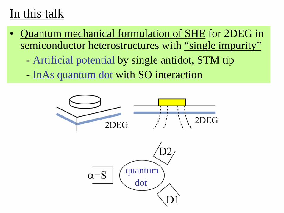
Conductance and Pz Pz for each channel in incident wave
25%
73%
Channel 1 can be injectedselectively using QPC
−+
−+
+−
=GGGGPz and eConductanc
Application to 3-terminal spin filter

2.3. Conclusions
• Formulation of extrinsic spin Hall effect (SHE) in 2D using partial wave expansion
• Enhanced SHE by resonant scattering by tuning attractive potential
• Three-terminal device including an antidot for spin injection, showing polarization ~30% for two channels and ~70% for single channel
ReferencesM. Eto and T. Yokoyama, J. Phys. Soc. Jpn. 78, 073710(2009); T. Yokoyama and M. Eto, PRB 80, 125311 (2009).

Outline
1. Introduction1.1. Spin-orbit interaction1.2. Spin Hall effect
2. Spin Hall effect in 2DEG with artificial potential
4. Search for Majorana fermions4.1. Topological quantum computer4.2. Majorana fermion
3. Semiconductor quantum dot3.1. Coulomb oscillation3.2. Spin Hall effect in quantum dot

• Quantum dots: zero-dimensional systems of nano-meter scale
• Transport through “quantum levels” in quantum dots• Quantum levels are controlled by gate voltage.
peak structure of current
Coulomb oscillation(Coulomb blockade between peaks)
3.1. Coulomb oscillation in quantum dot
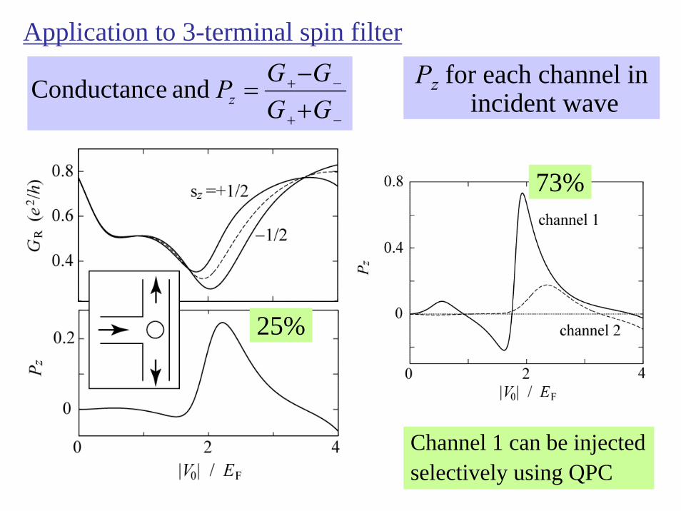
What are “quantum levels”?
1. In absence of electron-electron interaction, “quantum levels” are single-electron energy levels.
2. In presence of electron-electron interaction (charging energy), increase in energy to put an electron on the dot (electro-chemical potential):
1−−= NNN EEμ
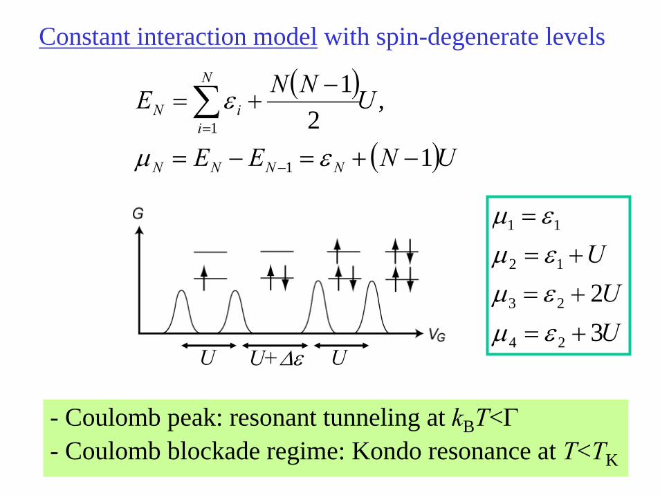
Constant interaction model with spin-degenerate levels
( )
( )UNEE
UNNE
NNNN
N
iiN
1
,2
1
1
1
−+=−=
−+=
−
=∑
εμ
ε
Discrete energy levels are occupied consecutively.Peak positions reflect the energy levels.
UU U+ΔεUU
U
32
24
23
12
11
+=+=+=
=
εμεμεμεμ
- Coulomb peak: resonant tunneling at kBT<Γ- Coulomb blockade regime: Kondo resonance at T<TK

Condition to observe Coulomb oscillation, blockade
(level spacing), (Charging energy) >> kBT, Γ
• Quantum fluctuation: “level broadening” Γ(due to finite lifetime by tunnel coupling to the leads)
( )
( )( )22
22
2
;,
21
2
,21
RL
RL
nknTkRL
VV
VV
dHk
+==Γ
+=
−= ∑=
πντ
νπ
εεδαπτ α
h
h
h
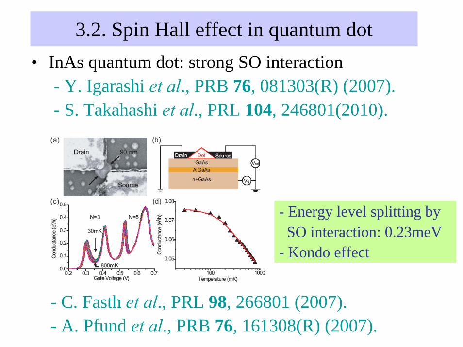
• InAs quantum dot: strong SO interaction- Y. Igarashi et al., PRB 76, 081303(R) (2007).- S. Takahashi et al., PRL 104, 246801(2010).
- Energy level splitting bySO interaction: 0.23meV
- Kondo effect
- C. Fasth et al., PRL 98, 266801 (2007).- A. Pfund et al., PRB 76, 161308(R) (2007).
3.2. Spin Hall effect in quantum dot

“Spin Hall effect” at quantum dot
• Strong SO interaction is present only in quantum dot• Multi-terminal system
- unpolarized current is injected from lead S- spin-polarized current to leads D1, D2,…
“Spin filter” effect
quantumdot
cf. Previous work for “open quantum dot” without tunnelbarriers: Krich and Halperin, PRB 78, 035338 (2008).
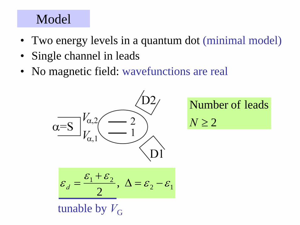
Model• Two energy levels in a quantum dot (minimal model)• Single channel in leads• No magnetic field: wavefunctions are real
1221 ,
2εεεεε −=Δ
+=d
2leads ofNumber
≥N
tunable by VG

( )UH ∇×⋅= pσh
λSO
212
02211
SOSO
SOSO
σh ⋅=
==
iH
HH
Quantization axis // hSO
⎟⎟⎠
⎞⎜⎜⎝
⎛ΔΔ±ΔΔ−
+=±=SO
SO1 dot, 2
1i
iH dσ
mε
( ) ( )122SO Ui ∇×= ph hλ
SOSO h=Δ
• SO interaction in the quantum dot
For details, seeEto and Yokoyama,
Poster WP-62

Three-terminal system
Γ≡Γ=Γ 1DS
1,321
2D21D22D11D1
2S1S
=−=
=
,,,,
,,
eeeeee
Γ=ΓΓ=Γ
Γ=ΓΓ=Γ
2 (d) (c)
5.0 (b)2.0 (a)
2D
2D
2D
2D
Γ=Δ 2.0SO
Γ=ΔΓ=−=Δ 2.012 εε
ΔSO=0.23 meVΓ ~ 1 meV

Γ≡Γ=Γ 1DS
1,321
2D21D22D11D1
2S1S
=−=
=
,,,,
,,
eeeeee
Γ=ΓΓ=Γ
Γ=ΓΓ=Γ
2 (d) (c)
5.0 (b)2.0 (a)
2D
2D
2D
2D
Γ=Δ 2.0SO
Γ=ΔΓ=−=Δ 2.012 εε
(1) Large spin polarization around current peakEnhancement of SHE by resonant tunneling
(2) Level spacing Δ ~ broadening ΓTwo levels should contribute to transport
(3) Control of SHE by tuning ΓD2 (tunnel coupling to D2)
Three-terminal system

3.3. Enhanced SHE by Kondo resonanceKondo effect in quantum dot• Spin S=1/2 in quantum dot + Fermi sea in leads• Spin-singlet state (S=0)
Many-body ground state(Binding energy:
Kondo temperature TK)
Resonant level at EFwith width of TK

• Addition and extraction energies ( )2
R2
L
B ,,
VV
TkEE
+=Γ
Γ>>−+
πν
Γ>>−+ ,, BTkEE
⎩⎨⎧
−=−=−+=−=
−
+
01
02
εμμμμεμμ
EUE
Coulomb blockade with single electron
• Sequential tunnel process is forbidden.• Higher-order tunnel process “cotunneling”

• Spin-flip by cotunneling
• Anti-ferromagnetic coupling between localized spinand conduction electrons
[ ] ( ) ⎟⎠⎞
⎜⎝⎛ +=⋅=+= −+↓
+↑+∑ EE
VJJccSJH kkkk
kk11 ,22 2
''
' sSL

Ground state with antiferromagnetic coupling
• Two interacting spins:
• One spin and Fermi sea:
( )21212
1Grd ↑↓−↓↑=
Conduction electrons coherently couple with a localizedspin (spin is completely screened).
Spin-singlet state
Kondo singlet state(Many-body state)
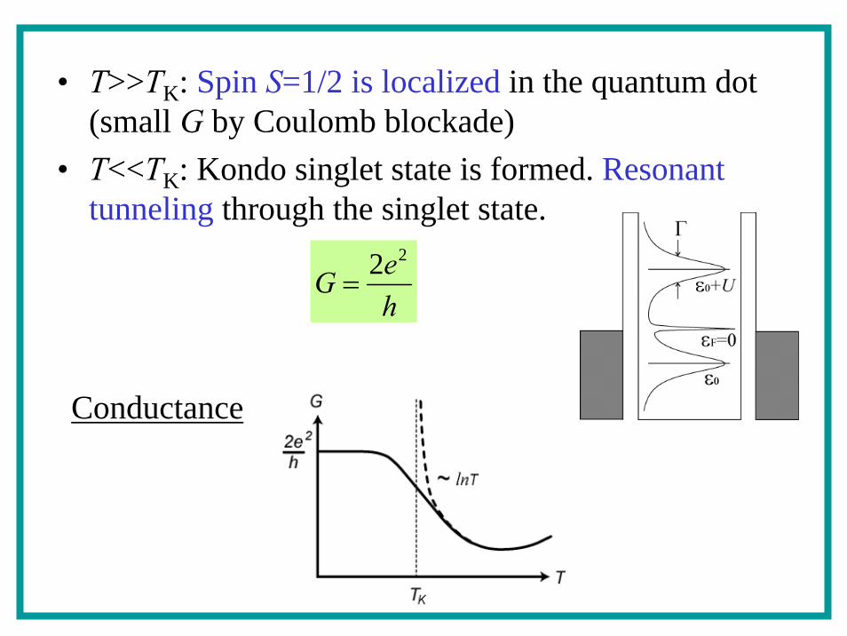
• T>>TK: Spin S=1/2 is localized in the quantum dot (small G by Coulomb blockade)
• T<<TK: Kondo singlet state is formed. Resonant tunneling through the singlet state.
heG
22=
Conductance

Two levels in quantum dot
12 εε −=Δ
(1) TK < Δ: level 2 is irrelevant
Spin S=1/2 in level 1 is screened out(conventional “spin SU(2)” Kondo effect)
(2) TK > Δ:Both pseudo-spin (levels 1 and 2) and spin S=1/2 arescreened out (SU(4) Kondo effect)
Crossover of (1) and (2): slave-boson mean-field theorycf. J. S. Lim et al., PRB 74, 205119 (2006).

Two-terminal system
−+ = ,1,1 GG
∞=U
Kondo regime : − εd << Γ
charge fluctuationregime: −εd ~ Γ

Three-terminal system
Γ≡Γ=Γ 1DS
1,321
2D21D22D11D1
2S1S
=−=
=
,,,,
,,
eeeeee
Γ=ΓΓ=Γ
Γ=ΓΓ=Γ
2 (d) (c)
5.0 (b)2.0 (a)
2D
2D
2D
2D
Γ=Δ 2.0SO
TK decreases with decreasing εd:- SU(4) Kondo: TK > Δ- SU(2) Kondo: TK < Δ
Γ=−=Δ 2.012 εε∞=U

3.4. Conclusions
• Formulation of spin Hall effect at quantum dot- needs two levels in the dot, more than two leads
• Enhancement of SHE by resonant tunneling and Kondo resonance (SU(4) Kondo effect)
[Observation by “inverse SHE”]• Ferromagnet (magnetization p) + InAs quantum dot:
Hamaya et al., APL (2007)
−+−
++
= ,1,11 2cos1
2cos1 GpGpG θθ θ: angle between
magnetization and hSO
[Reference]Eto and Yokoyama, J. Phys. Soc. Jpn. 79, 123711 (2010).

Outline
1. Introduction1.1. Spin-orbit interaction1.2. Spin Hall effect
2. Spin Hall effect with artificial potential
4. Search for Majorana fermions4.1. Topological quantum computer4.2. Majorana fermion
3. Semiconductor quantum dot3.1. Coulomb oscillation3.2. Spin Hall effect in quantum dot

• Conventional quantum computer(1) qubit: single electron spin
4.1. Topological quantum computer
(2) Easy to manipule using ESR, etc.(3) Decoherence problem: continuous phase error
↓+↑=ψ 10 CC
↓+↑⇒↓+↑ θieCCCC 1010
overcome by “quantum error correction”

• Topological quantum computer(1) Many-body states of interacting electrons
(2) Topologically protected:robust against local perturbation
(3) Manipulation by exchanging quasi-particlesNon-Abelian braiding statistics
states) ground e(degenerat ∑ Ψ=j
jjCψ
1 2 3

1 2 3 4 …
( ) ( )KK ,3,2,1,3,1,2 Ψ=Ψ
( ) ( )KK ,3,2,1,3,1,2 Ψ−=Ψ
( ) ( )KK ,3,2,1,3,1,2 Ψ=Ψ αie
Boson
Fermion
“Anyon”
Suggested for high Tc cuprates∞=U 2D,

1 2 3 4 …
( ) ( )∑ Ψ=Ψj
jiji C KK ,3,2,1,3,1,2 Non-Abelian
1 2 3 1 2 3
2 3 1 3 1 2
≠2112 TTTT ≠

Candidates• Fractional Quantum Hall effect with ν=5/2
• Half-quantum vortex in p-wave superconductorStrontium ruthenate Sr2Ru2O4: Science 331, 186 (2011).
( ) ( )↓↓−↑↑±Δ=Δ2
10 yx ikk
1,1 ±== zLL 1=S
“chiral states”clockwise vs. anticlockwise
Spin triplet“equal spin pairing”

- Usual spin-singlet superconductor
( ) ( )e
hn2
flux 2 =Φ⇒Δ=+Δ θπθ
- p-wave (chiral) superconductore
hn22
flux =Φ
Bogoliubov-de Gennes eq. yields quasi-particleoperators
( ) ( )EEvu−=
Ψ+Ψ=+
++
γγ
γ
( ) ( )00 ===∴ + EE γγ
1=zL
Vortexcore
1−=zL

4.2. Majorana fermions
• Creation and annihilation operators are self conjugate
- possibly neutrino- Half-quantum vortex at E=0
γγ =+
• 2n half-quantum vortices: ( )niii 2,,2,1 L==+ γγ
( )( )⎩
⎨⎧
−=+=
−+
−
2/2/
212
212
iii
iii
ididγγγγ
n “usual” fermions0,1== +
iii ddn
2n degenerate states
* Majorana fermion is a “half” of usual fermion

• 2n degenerate states• Non-Abelian braiding statistices
1
1
=−=
>−=
jiTTTTTT
jiTTTT
jijiji
ijji
* Majorana fermions enable topological quantum computation
D. A. Ivanov, PRL 86, 268 (2001).

4.3. Majorana fermions in semiconductor
• Rashba spin-orbit interaction
2DEG
• S-wave superconductivity (proximity effect) + magnetic field
1D
Similar to chiral superconductivity
cf. Wray’s talk: topological insulator + superconductivity

(1) Semiconductor thin film
(2) InAs nanowire
J.D.Sau et al., PRL 104,040502 (2010)
J. Alicea et al., Nat. Phys. 7,412 (2011)
A pair of Majoranas


![Jesko Sirker, and Tapash Chakraborty arXiv:1802.00788v1 ... · arXiv:1802.00788v1 [cond-mat.mes-hall] 2 Feb 2018 Unique Spin Vortices in Quantum Dots with Spin-orbit Couplings Wenchen](https://static.fdocuments.net/doc/165x107/5f079ca97e708231d41dda35/jesko-sirker-and-tapash-chakraborty-arxiv180200788v1-arxiv180200788v1-cond-matmes-hall.jpg)